Embed Size (px)
Citation preview
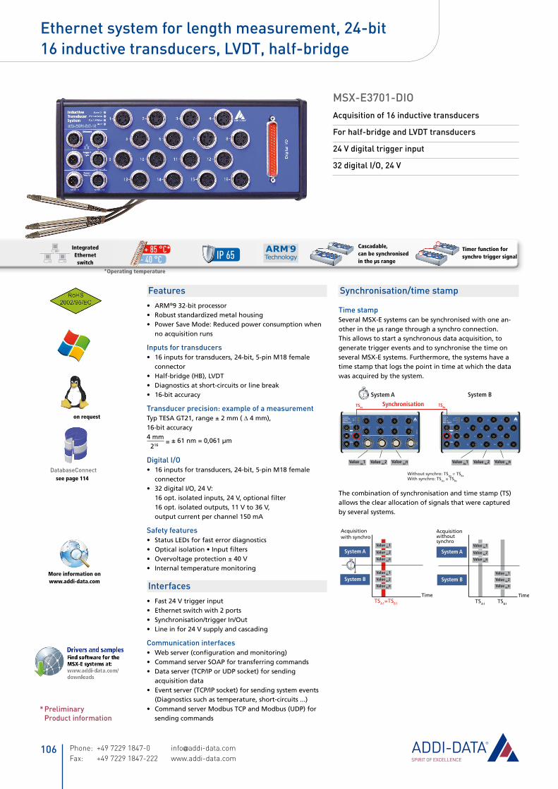
MSX-E3701-DIOAcquisition of 16 inductive transducers
For half-bridge and LVDT transducers
24 V digital trigger input
32 digital I/O, 24 V
Temperaturbereich-40 °C bis 85 °C
Temperaturbereich-40 °C bis 85 °C
Kaskadierbar
Synchronisierbarin µs-Bereich
Mehr Info aufwww.addi-data.com
Schutzart IP 65
KaskadierbarEdelstahl
Synchronisierbarin µs-Bereich
Edelstahl
Temperaturbereich-40 °C bis 85 °C
Temperaturbereich-40 °C bis 85 °C
Kaskadierbar
Synchronisierbarin µs-Bereich
Mehr Info aufwww.addi-data.com
Schutzart IP 65
KaskadierbarEdelstahl
Synchronisierbarin µs-Bereich
Edelstahl
Cascadable, can be synchronised in the µs range
Timer function for synchro trigger signal
Ethernet system for length measurement, 24-bit 16 inductive transducers, LVDT, half-bridge
on request
see page 114DatabaseConnect
More information on www.addi-data.com
Temperaturbereich-40 °C bis 85 °C
Temperaturbereich-40 °C bis 85 °C
Kaskadierbar
Synchronisierbarin µs-Bereich
Mehr Info aufwww.addi-data.com
Schutzart IP 65
KaskadierbarEdelstahl
Synchronisierbarin µs-Bereich
Edelstahl
- 40 °C + 85 °C*
* Preliminary Product information
IP 65
FeaturesARM• ®932-bitprocessorRobuststandardizedmetalhousing•PowerSaveMode:Reducedpowerconsumptionwhen•noacquisitionruns
Inputs for transducers16inputsfortransducers,24-bit,5-pinM18female•connectorHalf-bridge(HB),LVDT•Diagnosticsatshort-circuitsorlinebreak•16-bitaccuracy•
Transducer precision: example of a measurementTypTESAGT21,range±2mm(∆4mm),16-bitaccuracy4mm
=±61nm=0,061µm
216
Digital I/O16inputsfortransducers,24-bit,5-pinM18female•connector32digitalI/O,24V:•16opt.isolatedinputs,24V,optionalfilter16opt.isolatedoutputs,11Vto36V,outputcurrentperchannel150mA
Safety featuresStatusLEDsforfasterrordiagnostics•Opticalisolation•Inputfilters•Overvoltageprotection±40V•Internaltemperaturemonitoring•
InterfacesFast24Vtriggerinput•Ethernetswitchwith2ports•Synchronisation/triggerIn/Out•Lineinfor24Vsupplyandcascading•
Communication interfacesWebserver(configurationandmonitoring)•CommandserverSOAPfortransferringcommands•Dataserver(TCP/IPorUDPsocket)forsending•acquisitiondataEventserver(TCP/IPsocket)forsendingsystemevents•(Diagnosticssuchastemperature,short-circuits...)CommandserverModbusTCPandModbus(UDP)for•sendingcommands
Synchronisation/time stamp
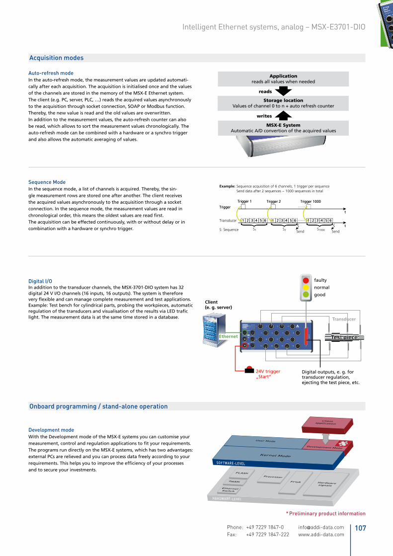
Time stampSeveralMSX-Esystemscanbesynchronisedwithonean-otherintheµsrangethroughasynchroconnection.Thisallowstostartasynchronousdataacquisition,togeneratetriggereventsandtosynchronisethetimeonseveralMSX-Esystems.Furthermore,thesystemshaveatimestampthatlogsthepointintimeatwhichthedatawasacquiredbythesystem.
CounterDigital I/OSystem
MSX-E1701
CH0 CH1 CH2 CH3 CH4 CH5 CH6 CH7
Counter 0 Counter 2 Counter 3Counter 1
CH8 CH9 CH10 CH11 CH12 CH13 CH14 CH15
Dig
ital
I/O
Co
un
ter
AnalogInputSystem
MSX-E3011
System BSystem A
Value Ax1 Value Ax2 Value Axn Value Bx1 Value Bx2 Value Bxn
Without synchro: TSAx ≠ TSBxWith synchro: TSAx = TSBx
SynchronisationTSAxTSBx
Thecombinationofsynchronisationandtimestamp(TS)allowstheclearallocationofsignalsthatwerecapturedbyseveralsystems.
Acquisitionwithoutsynchro
Value Ax1
Value Ax2
Value Axn
Time
System B
System A
TSA1
Value Bx1
Value Bx2
Value Bxn
TSB1
Value Ax1
Value Ax2
Value Axn
Value Bx1
Value Bx2
Value Bxn
Time
Acquisitionwith synchro
System B
System A
TSA1=TSB1
Integrated Ethernet switch
*Operating temperature
Phone: +49 7229 1847-0 [email protected] Fax: +49 7229 1847-222 www.addi-data.com
106
* Preliminary product information
Auto-refresh modeIntheauto-refreshmode,themeasurementvaluesareupdatedautomati-callyaftereachacquisition.TheacquisitionisinitialisedonceandthevaluesofthechannelsarestoredinthememoryoftheMSX-EEthernetsystem.Theclient(e.g.PC,server,PLC,…)readstheacquiredvaluesasynchronouslytotheacquisitionthroughsocketconnection,SOAPorModbusfunction.Thereby,thenewvalueisreadandtheoldvaluesareoverwritten.Inadditiontothemeasurementvalues,theauto-refreshcountercanalsoberead,whichallowstosortthemeasurementvalueschronologically.Theauto-refreshmodecanbecombinedwithahardwareorasynchrotriggerandalsoallowstheautomaticaveragingofvalues.
Acquisition modes
Applicationreads all values when needed
reads
writes
Storage locationValues of channel 0 to n + auto refresh counter
MSX-E SystemAutomatic A/D convertion of the acquired values
Sequence ModeInthesequencemode,alistofchannelsisacquired.Thereby,thesin-glemeasurementrowsarestoredoneafteranother.Theclientreceivestheacquiredvaluesasynchronouslytotheacquisitionthroughasocketconnection.Inthesequencemode,themeasurementvaluesarereadinchronologicalorder,thismeanstheoldestvaluesarereadfirst.Theacquisitioncanbeeffectedcontinuously,withorwithoutdelayorincombinationwithahardwareorsynchrotrigger.
Development modeWiththeDevelopmentmodeoftheMSX-Esystemsyoucancustomiseyourmeasurement,controlandregulationapplicationstofityourrequirements.TheprogramsrundirectlyontheMSX-Esystems,whichhastwoadvantages:externalPCsarerelievedandyoucanprocessdatafreelyaccordingtoyourrequirements.Thishelpsyoutoimprovetheefficiencyofyourprocessesandtosecureyourinvestments.
Example: Sequence acquisition of 6 channels, 1 trigger per sequence Send data after 2 sequences − 1000 sequences in total
t
t1 2 3 4 5 6 1 2 3 4 5 6 1 2 3 4 5 6
Trigger
Trigger 1 Trigger 2 Trigger 1000
Transducer
S1 S2 S1000S: Sequence Send Send
t
t1 2 3 4 5 6 1 2 3 4 5 6 1 2 3 4 5 6
Trigger
Trigger 1 Trigger 2 Trigger 1000
Onboard programming / stand-alone operation
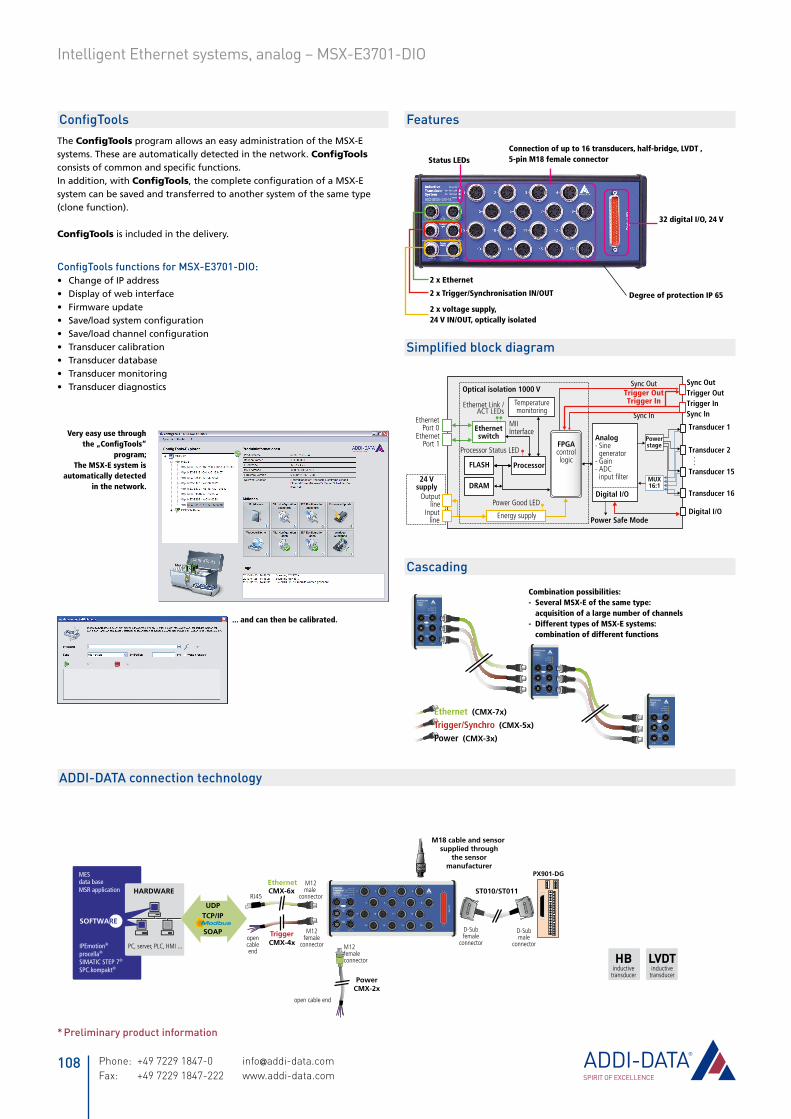
Digital I/OInadditiontothetransducerchannels,theMSX-3701-DIOsystemhas32digital24VI/Ochannels(16inputs,16outputs).Thesystemisthereforeveryflexibleandcanmanagecompletemeasurementandtestapplications.Example:Testbenchforcylindricalparts,probingtheworkpieces,automaticregulationofthetransducersandvisualisationoftheresultsviaLEDtraficlight.Themeasurementdataisatthesametimestoredinadatabase.
InductiveTransducerSystem
Dig
ital
I/O
1 – 2 – 3 – 4 –
9 – 10 – 11 – 12 –
5 – 6 – 7 – 8 –
13 – 14 – 15 – 16 –
Test piece
Digital outputs, e. g. for transducer regulation, ejecting the test piece, etc.
24V trigger„Start“
Client(e. g. server)
Transducer
faulty
normal
good
Ethernet
107Phone: +49 7229 1847-0 [email protected] Fax: +49 7229 1847-222 www.addi-data.com
Intelligent Ethernet systems, analog – MSX-E3701-DIO
* Preliminary product information
digital24 V
digital5 V
currentI
sensorICP
thermocoupleelement
voltageU
temperature
NTC
24 Vdig. input
NPNC
EB
Pt100
HBinductive
transducer
LVDTinductive
transducer
VLDTinductive
transducer
serialRS232
serialRS422
serialRS485
serialTTY
SSI
incremental
A
B
PWM 1 VPP
A
B
Sin
Cos
11 µAPP
A
B
Sin
Cos
DMS
D-Subfemale
connector
37x
PX901-DG
D-Submale
connector
ST010/ST011InductiveTransducerSystem
Dig
ital
I/O
1 – 2 – 3 – 4 –
9 – 10 – 11 – 12 –
5 – 6 – 7 – 8 –
13 – 14 – 15 – 16 –
PowerCMX-2x
RJ45
EthernetCMX-6x
M12male
connector
CMX-4xopencableend
M12female
connector
Trigger
open cable end
M12femaleconnector
PC, server, PLC, HMI ...
HARDWARE
UDPTCP/IP
SOAP
MESdata baseMSR application
IPEmotion®
procella®
SIMATIC STEP 7®
SPC.kompakt®
SOFTWARE
M18 cable and sensor supplied through
the sensormanufacturer
ConfigToolsTheConfigToolsprogramallowsaneasyadministrationoftheMSX-Esystems.Theseareautomaticallydetectedinthenetwork.ConfigToolsconsistsofcommonandspecificfunctions.Inaddition,withConfigTools,thecompleteconfigurationofaMSX-Esystemcanbesavedandtransferredtoanothersystemofthesametype(clonefunction).
ConfigToolsisincludedinthedelivery.
ConfigTools functions for MSX-E3701-DIO:ChangeofIPaddress•Displayofwebinterface•Firmwareupdate•Save/loadsystemconfiguration•Save/loadchannelconfiguration•Transducercalibration•Transducerdatabase•Transducermonitoring•Transducerdiagnostics•
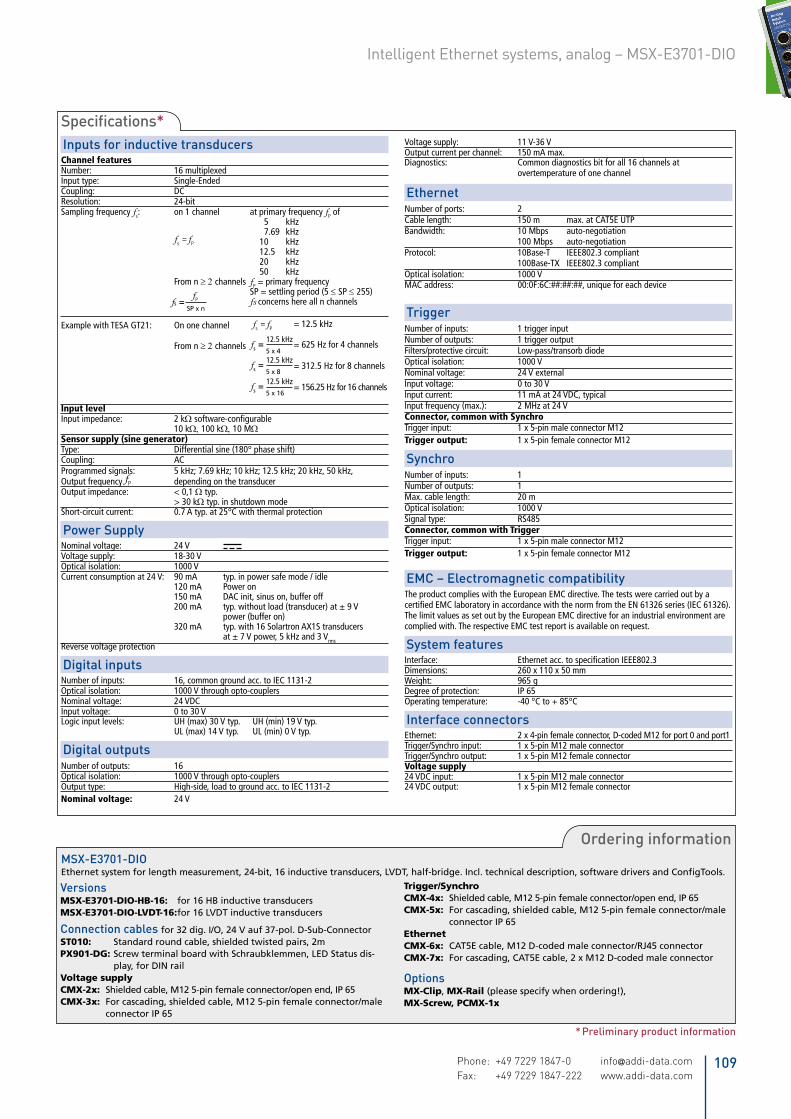
32 digital I/O, 24 V
Trigger OutSync Out
Trigger InTrigger InTrigger Out
Sync In
Sync Out
Sync In
Outputline
Inputline
24 Vsupply
Energy supply
Optical isolation 1000 V
Processor
FPGAcontrollogic
EthernetPort 0
Ethernet Link /ACT LEDs
MIIInterfaceEthernet
switch
FLASH
DRAM
EthernetPort 1
Power Good LED
Processor Status LED
Temperaturemonitoring
Transducer 1Powerstage
MUX16:1
Transducer 2
Transducer 15
Transducer 16
Analog- Sine generator- Gain- ADC input filter
Power Safe Mode
.
.
.
Digital I/O
Digital I/O
2 x voltage supply, 24 V IN/OUT, optically isolated
2 x Trigger/Synchronisation IN/OUT
2 x Ethernet
Status LEDsConnection of up to 16 transducers, half-bridge, LVDT , 5-pin M18 female connector
Degree of protection IP 65
... and can then be calibrated.
MultifunctionSystem
Power On
Port 0 ACT/Link
Port 1 ACT/Link
Status
Port 0
Trig/Sync In Trig/Sync Out
24 VDC In 24 VDC Out
Port 1
Ethernet
Trigger/Sync
PowerSupply 1
MultifunctionSystem
Power On
Port 0 ACT/Link
Port 1 ACT/Link
Status
Port 0
Trig/Sync In Trig/Sync Out
24 VDC In 24 VDC Out
Port 1
Ethernet
Trigger/Sync
PowerSupply 2
MultifunctionSystem
Power On
Port 0 ACT/Link
Port 1 ACT/Link
Status
Port 0
Trig/Sync In Trig/Sync Out
24 VDC In 24 VDC Out
Port 1
Ethernet
Trigger/Sync
PowerSupply ...Ethernet (CMX-7x)
Trigger/Synchro (CMX-5x)
Power (CMX-3x)
Simplified block diagram
Cascading
Combination possibilities:- Several MSX-E of the same type: acquisition of a large number of channels- Different types of MSX-E systems: combination of different functions
Features
ADDI-DATA connection technology
Very easy use through the „ConfigTools“
program; The MSX-E system is
automatically detected in the network.
Phone: +49 7229 1847-0 [email protected] Fax: +49 7229 1847-222 www.addi-data.com
108
Intelligent Ethernet systems, analog – MSX-E3701-DIO
* Preliminary product information
Ordering informationMSX-E3701-DIOEthernetsystemforlengthmeasurement,24-bit,16inductivetransducers,LVDT,half-bridge.Incl.technicaldescription,softwaredriversandConfigTools.
VersionsMSX-E3701-DIO-HB-16: for16HBinductivetransducersMSX-E3701-DIO-LVDT-16:for16LVDTinductivetransducers
Connection cables for32dig.I/O,24Vauf37-pol.D-Sub-ConnectorST010: Standardroundcable,shieldedtwistedpairs,2mPX901-DG:ScrewterminalboardwithSchraubklemmen,LEDStatusdis-
play,forDINrailVoltagesupplyCMX-2x: Shieldedcable,M125-pinfemaleconnector/openend,IP65CMX-3x: Forcascading,shieldedcable,M125-pinfemaleconnector/male
connectorIP65
Trigger/SynchroCMX-4x: Shieldedcable,M125-pinfemaleconnector/openend,IP65CMX-5x: Forcascading,shieldedcable,M125-pinfemaleconnector/male
connectorIP65EthernetCMX-6x: CAT5Ecable,M12D-codedmaleconnector/RJ45connectorCMX-7x: Forcascading,CAT5Ecable,2xM12D-codedmaleconnector
OptionsMX-Clip,MX-Rail(pleasespecifywhenordering!),MX-Screw,PCMX-1x
Inputs for inductive transducersChannel featuresNumber: 16 multiplexedInput type: Single-Ended Coupling: DCResolution: 24-bitSampling frequency fs: on 1 channel at primary frequency fP of 5 kHz 7.69 kHz fs = fP 10 kHz 12.5 kHz 20 kHz 50 kHz From n ≥ 2 channels fP = primary frequency SP = settling period (5 ≤ SP ≤ 255) fs concerns here all n channels
Example with TESA GT21: On one channel fs = fP = 12.5 kHz From n ≥ 2 channels = 625 Hz for 4 channels = 312.5 Hz for 8 channels = 156.25 Hz for 16 channels
Input levelInput impedance: 2 kΩ software-configurable 10 kΩ, 100 kΩ, 10 MΩSensor supply (sine generator)Type: Differential sine (180° phase shift)Coupling: ACProgrammed signals: 5 kHz; 7.69 kHz; 10 kHz; 12.5 kHz; 20 kHz, 50 kHz, Output frequency fP depending on the transducerOutput impedance: < 0,1 Ω typ. > 30 kΩ typ. in shutdown modeShort-circuit current: 0.7 A typ. at 25°C with thermal protection
Power Supply Nominal voltage: 24 V Voltage supply: 18-30 V Optical isolation: 1000 V Current consumption at 24 V: 90 mA typ. in power safe mode / idle 120 mA Power on 150 mA DAC init, sinus on, buffer off 200 mA typ. without load (transducer) at ± 9 V power (buffer on) 320 mA typ. with 16 Solartron AX1S transducers at ± 7 V power, 5 kHz and 3 VrmsReverse voltage protection
Digital inputsNumber of inputs: 16, common ground acc. to IEC 1131-2Optical isolation: 1000 V through opto-couplersNominal voltage: 24 VDCInput voltage: 0 to 30 VLogic input levels: UH (max) 30 V typ. UH (min) 19 V typ. UL (max) 14 V typ. UL (min) 0 V typ.
Digital outputsNumber of outputs: 16Optical isolation: 1000 V through opto-couplersOutput type: High-side, load to ground acc. to IEC 1131-2Nominal voltage: 24 V
Voltage supply: 11 V-36 VOutput current per channel: 150 mA max.Diagnostics: Common diagnostics bit for all 16 channels at overtemperature of one channel
EthernetNumber of ports: 2Cable length: 150 m max. at CAT5E UTP Bandwidth: 10 Mbps auto-negotiation 100 Mbps auto-negotiation Protocol: 10Base-T IEEE802.3 compliant 100Base-TX IEEE802.3 compliant Optical isolation: 1000 VMAC address: 00:0F:6C:##:##:##, unique for each device
TriggerNumber of inputs: 1 trigger inputNumber of outputs: 1 trigger outputFilters/protective circuit: Low-pass/transorb diode Optical isolation: 1000 VNominal voltage: 24 V external Input voltage: 0 to 30 VInput current: 11 mA at 24 VDC, typical Input frequency (max.): 2 MHz at 24 VConnector, common with SynchroTrigger input: 1 x 5-pin male connector M12Trigger output: 1 x 5-pin female connector M12
SynchroNumber of inputs: 1Number of outputs: 1Max. cable length: 20 mOptical isolation: 1000 VSignal type: RS485Connector, common with TriggerTrigger input: 1 x 5-pin male connector M12Trigger output: 1 x 5-pin female connector M12
EMC – Electromagnetic compatibilityThe product complies with the European EMC directive. The tests were carried out by a certified EMC laboratory in accordance with the norm from the EN 61326 series (IEC 61326). The limit values as set out by the European EMC directive for an industrial environment are complied with. The respective EMC test report is available on request.
System featuresInterface: Ethernet acc. to specification IEEE802.3Dimensions: 260 x 110 x 50 mmWeight: 965 gDegree of protection: IP 65Operating temperature: -40 °C to + 85°C
Interface connectorsEthernet: 2 x 4-pin female connector, D-coded M12 for port 0 and port1Trigger/Synchro input: 1 x 5-pin M12 male connectorTrigger/Synchro output: 1 x 5-pin M12 female connectorVoltage supply24 VDC input: 1 x 5-pin M12 male connector24 VDC output: 1 x 5-pin M12 female connector
Specifications*
fs=
fP
SPxn
fs=12.5 kHz
5x4
fs=12.5 kHz
5x8
fs=12.5 kHz
5x16
109Phone: +49 7229 1847-0 [email protected] Fax: +49 7229 1847-222 www.addi-data.com
Intelligent Ethernet systems, analog – MSX-E3701-DIO