Embed Size (px)
Citation preview

EtherNet/IP DEVICE CONFIGURATION
A Step by Step Guide
4/7/365 Technical Support USA 1.800.709.3309 | CAN 1.800.265.9493 www.trelectronic.com
EtherNet/IP Device Configuration A Step By Step Guide Rev 7.0
1. RSLINX COMMUNICATION SETUP
Configure a new driver in RSLinx.
Select Ethernet Devices from the pull down menu.
4/7/365 Technical Support USA 1.800.709.3309 | CAN 1.800.265.9493 www.trelectronic.com
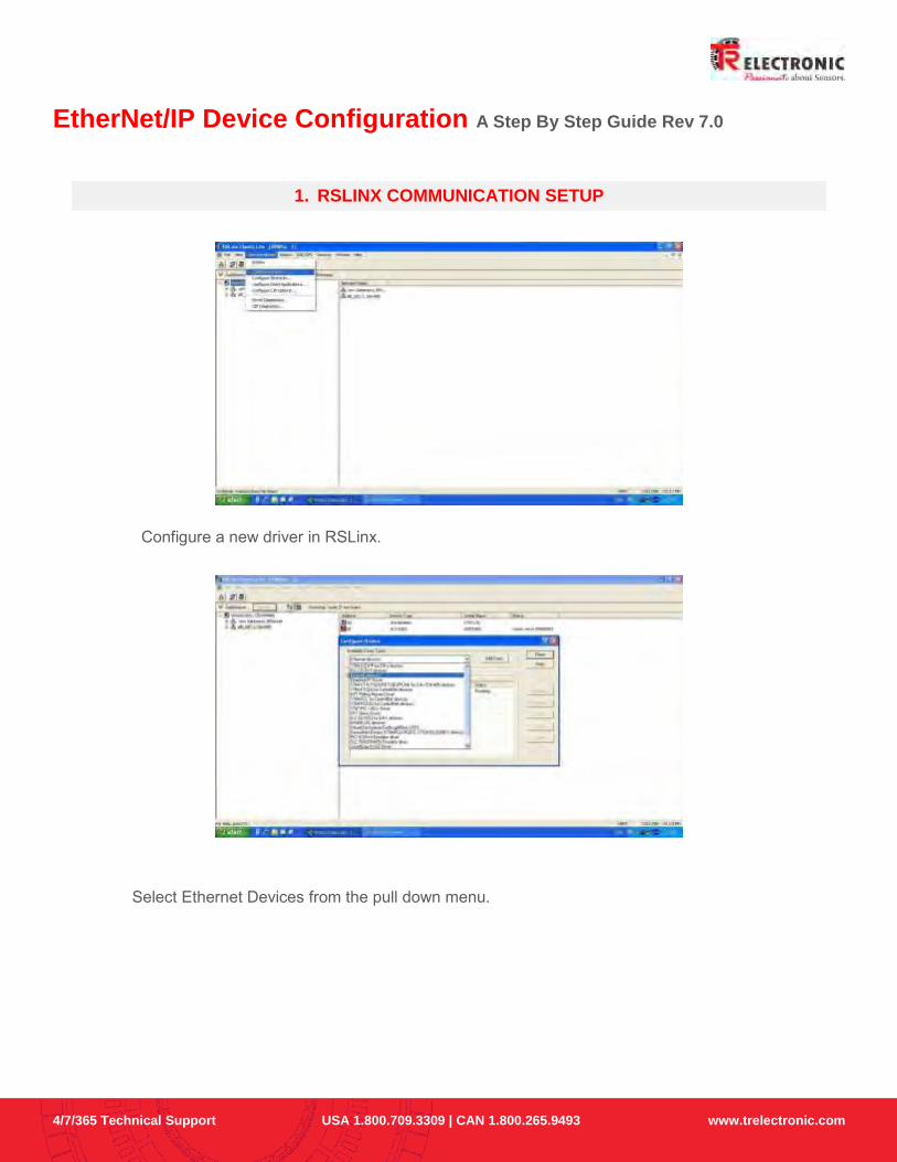
Add new driver for Ethernet Device. Add the IP address for each device on the network (host computer, PLC, Ethernet encoder, etc.)
All devices must have IP addresses in the same range. Example: 192.168.1.XXX NOTE: Add “:EIP” as a suffix to the IP address for 65 series encoders, NOT for 58 series encoders.
4/7/365 Technical Support USA 1.800.709.3309 | CAN 1.800.265.9493 www.trelectronic.com
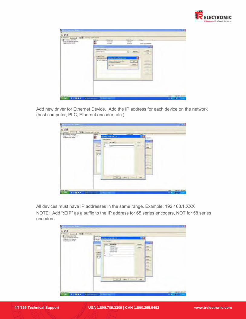
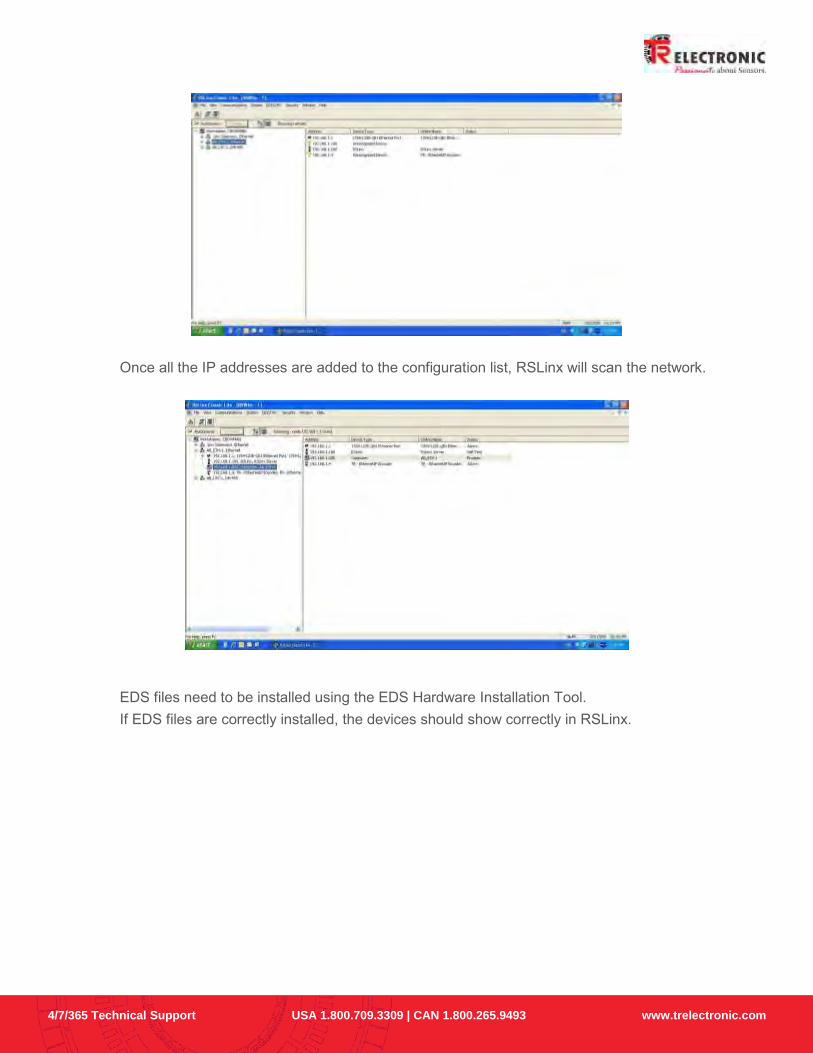
Once all the IP addresses are added to the configuration list, RSLinx will scan the network.
EDS files need to be installed using the EDS Hardware Installation Tool. If EDS files are correctly installed, the devices should show correctly in RSLinx.
4/7/365 Technical Support USA 1.800.709.3309 | CAN 1.800.265.9493 www.trelectronic.com
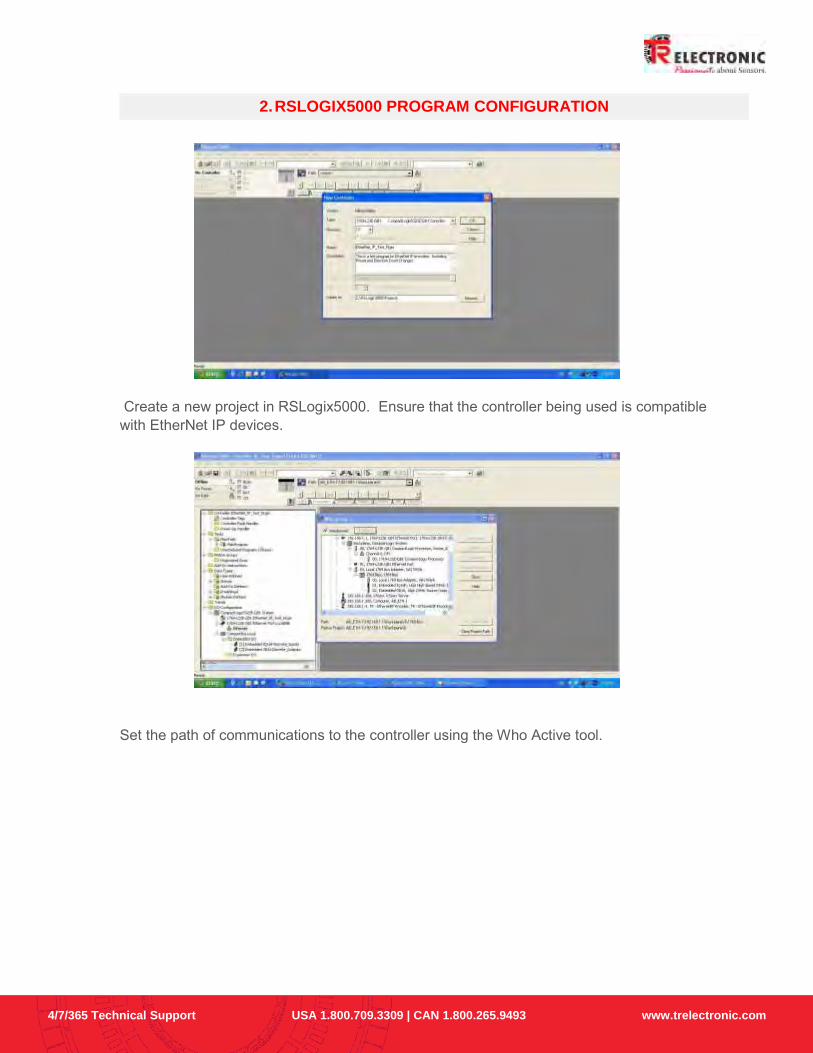
2. RSLOGIX5000 PROGRAM CONFIGURATION
Create a new project in RSLogix5000. Ensure that the controller being used is compatible with EtherNet IP devices.
Set the path of communications to the controller using the Who Active tool.
4/7/365 Technical Support USA 1.800.709.3309 | CAN 1.800.265.9493 www.trelectronic.com
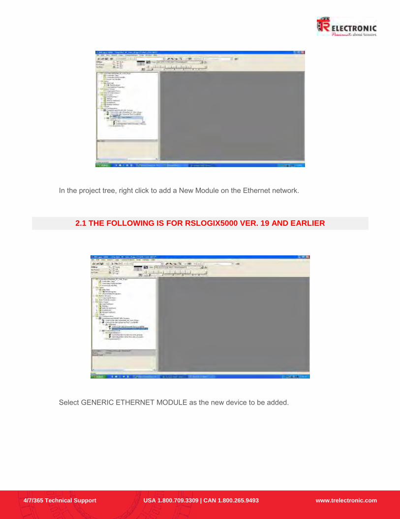
In the project tree, right click to add a New Module on the Ethernet network.
2.1 THE FOLLOWING IS FOR RSLOGIX5000 VER. 19 AND EARLIER
Select GENERIC ETHERNET MODULE as the new device to be added.

4/7/365 Technical Support USA 1.800.709.3309 | CAN 1.800.265.9493 www.trelectronic.com
Configure the device as shown. The name and IP address can be changed as needed.
The new device will now show in the Project Tree. New Controller Tags have also been created for the device.
Download the program to the controller.
4/7/365 Technical Support USA 1.800.709.3309 | CAN 1.800.265.9493 www.trelectronic.com
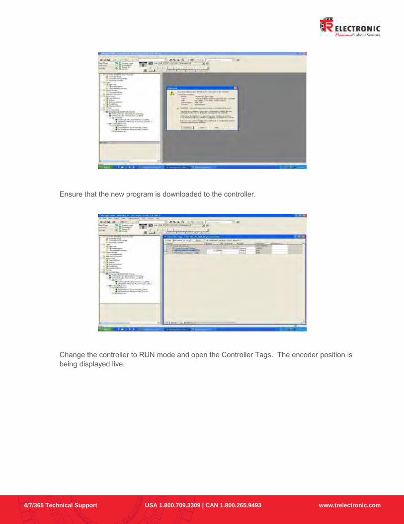
Ensure that the new program is downloaded to the controller.
Change the controller to RUN mode and open the Controller Tags. The encoder position is being displayed live.
4/7/365 Technical Support USA 1.800.709.3309 | CAN 1.800.265.9493 www.trelectronic.com
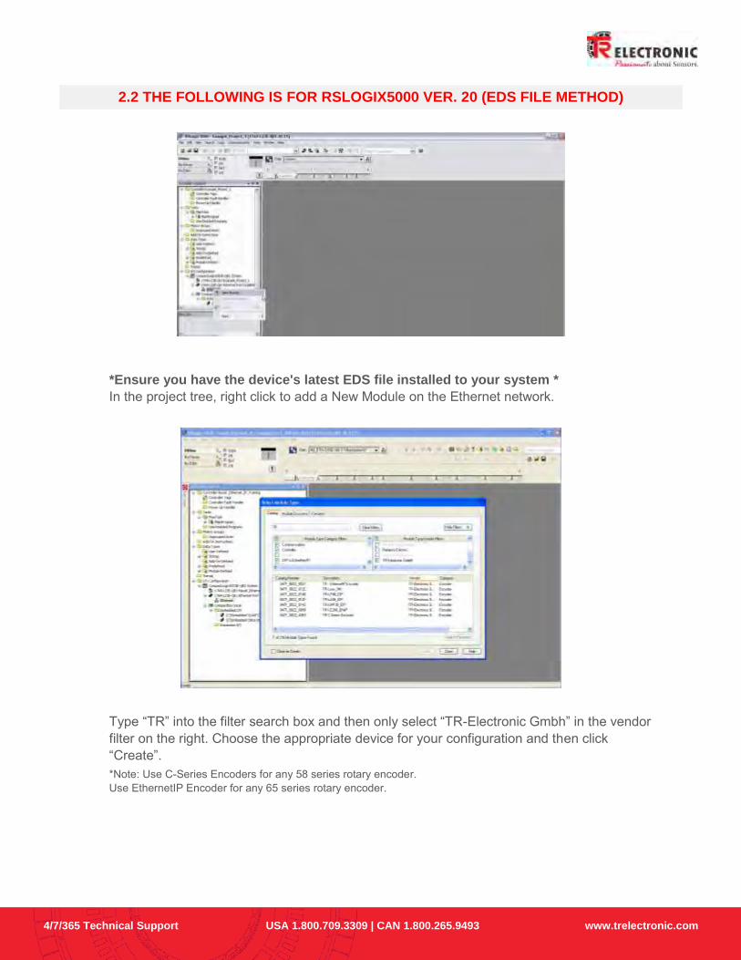
2.2 THE FOLLOWING IS FOR RSLOGIX5000 VER. 20 (EDS FILE METHOD)
*Ensure you have the device's latest EDS file installed to your system *
In the project tree, right click to add a New Module on the Ethernet network.
Type “TR” into the filter search box and then only select “TR-Electronic Gmbh” in the vendor filter on the right. Choose the appropriate device for your configuration and then click “Create”. *Note: Use C-Series Encoders for any 58 series rotary encoder. Use EthernetIP Encoder for any 65 series rotary encoder.
4/7/365 Technical Support USA 1.800.709.3309 | CAN 1.800.265.9493 www.trelectronic.com
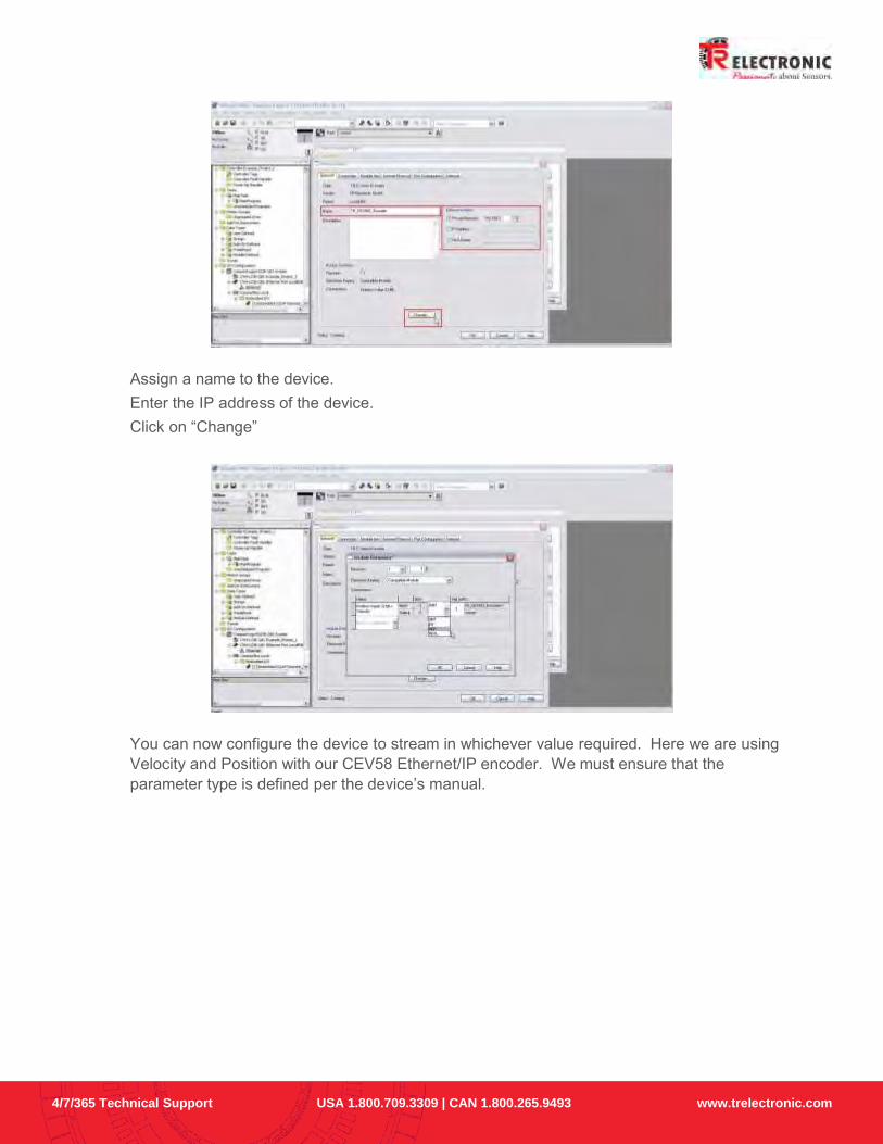
Assign a name to the device. Enter the IP address of the device. Click on “Change”
You can now configure the device to stream in whichever value required. Here we are using Velocity and Position with our CEV58 Ethernet/IP encoder. We must ensure that the parameter type is defined per the device’s manual.
4/7/365 Technical Support USA 1.800.709.3309 | CAN 1.800.265.9493 www.trelectronic.com
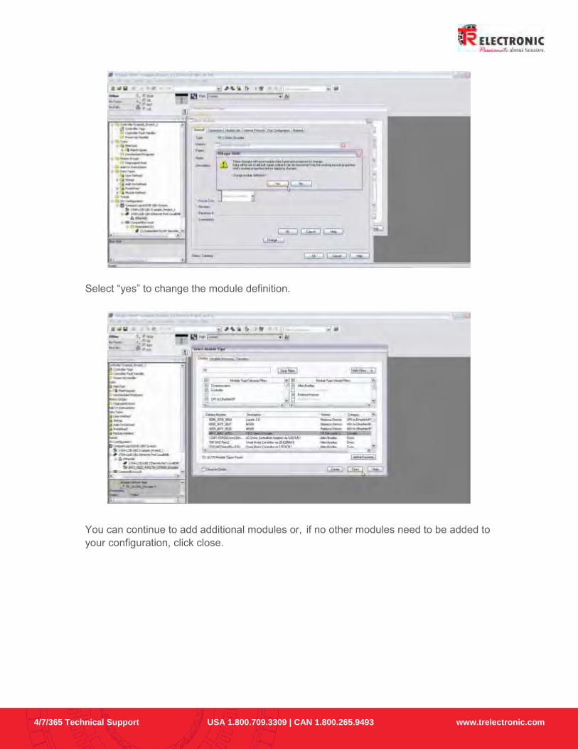
Select “yes” to change the module definition.
You can continue to add additional modules or, if no other modules need to be added to your configuration, click close.

4/7/365 Technical Support USA 1.800.709.3309 | CAN 1.800.265.9493 www.trelectronic.com
The new device will now show in the Project Tree. New Controller Tags have also been created for the device. Download the program to the controller. Ensure that the new program is downloaded to the controller.
Change the controller toRUN mode and open the Controller Tags. The encoder position and velocity is being displayed live.
Here, we have the Data[0] as Position, and Data[1] as velocity in RPM as per the device’s manual.
*Note* For Section 3 & 4 of this guide, our project name will be “Ethernet_IP_Test_Prgm” and our device name will be “Rotary_Encoder_1”
4/7/365 Technical Support USA 1.800.709.3309 | CAN 1.800.265.9493 www.trelectronic.com
3. PROGRAMMING FUNCTIONS
The following are some generic software functions that might be useful in your application. Not every function will be applicable to each type of encoder/laser; and attribute values may change from one product to another. Please refer to the specific product manual for more information.
3.1 DIRECTION CHANGE
3.1.1 Creating Tags
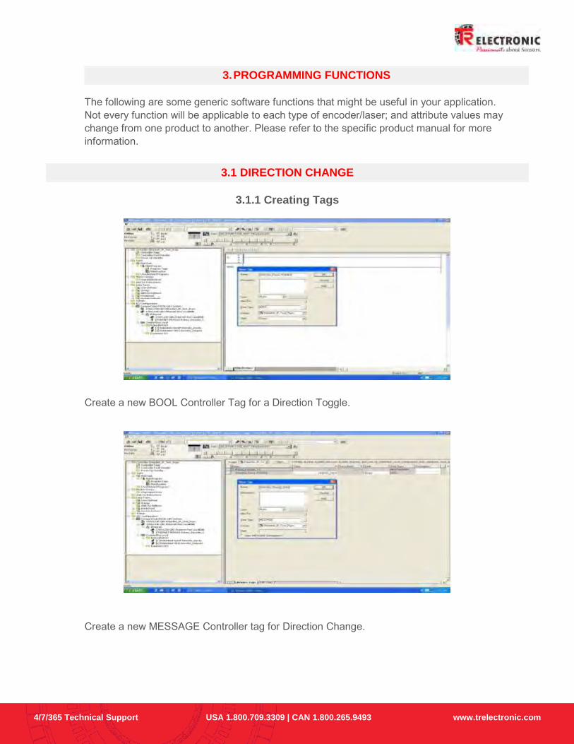
Create a new BOOL Controller Tag for a Direction Toggle.
Create a new MESSAGE Controller tag for Direction Change.

4/7/365 Technical Support USA 1.800.709.3309 | CAN 1.800.265.9493 www.trelectronic.com
Create a new DINT Controller Tag for Direction Change.
Create a new MESSAGE Controller for Accept Parameters.
4/7/365 Technical Support USA 1.800.709.3309 | CAN 1.800.265.9493 www.trelectronic.com
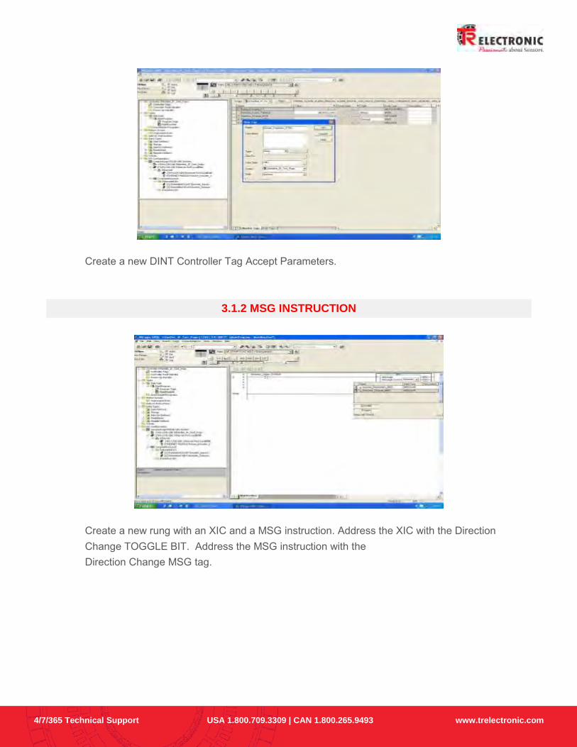
Create a new DINT Controller Tag Accept Parameters.
3.1.2 MSG INSTRUCTION
Create a new rung with an XIC and a MSG instruction. Address the XIC with the Direction Change TOGGLE BIT. Address the MSG instruction with the Direction Change MSG tag.
4/7/365 Technical Support USA 1.800.709.3309 | CAN 1.800.265.9493 www.trelectronic.com
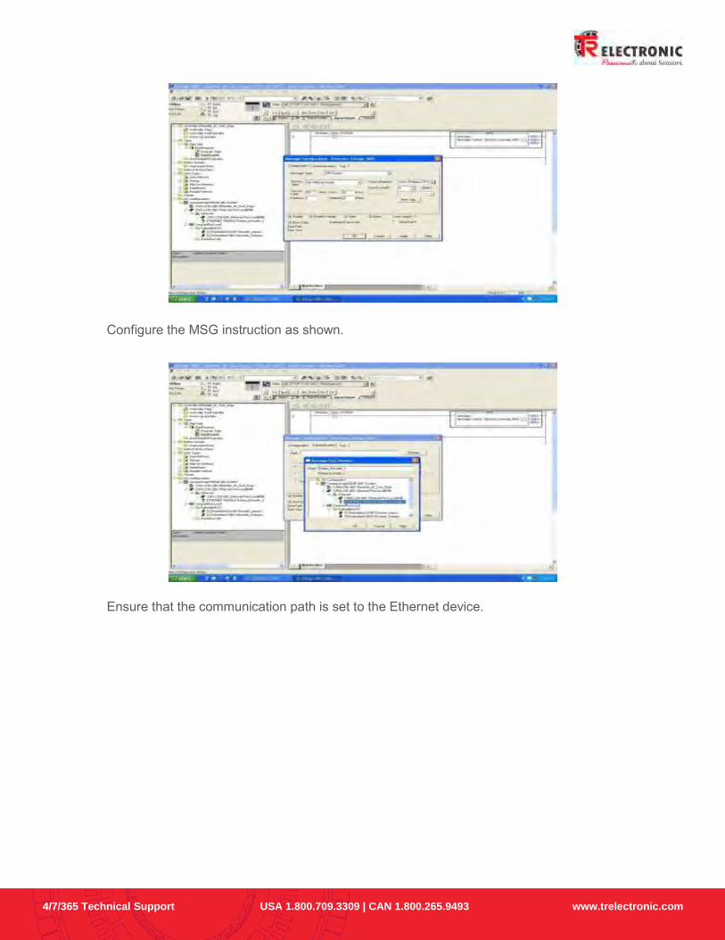
Configure the MSG instruction as shown.
Ensure that the communication path is set to the Ethernet device.

4/7/365 Technical Support USA 1.800.709.3309 | CAN 1.800.265.9493 www.trelectronic.com
Add a Branch with another MSG instruction. Address the MSG instruction with the Accept Parameter MSG tag.
Configure the MSG instruction as shown.

4/7/365 Technical Support USA 1.800.709.3309 | CAN 1.800.265.9493 www.trelectronic.com
Ensure that the communication path is set to the Ethernet device.
3.1.3 ONLINE
Ensure the controller is in RUN Mode. Open the Control Tag Window. Set Direction Change DINT tag to a value of 1. Set Accept Parameter DINT tag to a value of 1.

4/7/365 Technical Support USA 1.800.709.3309 | CAN 1.800.265.9493 www.trelectronic.com
Toggle the Direction Change Toggle bit. The encoder position will change, and the encoder will now count in the opposite direction.
3.2 PRESET
3.2.1 Creating Tags
Create a new BOOL Controller Tag for a Preset Toggle.

4/7/365 Technical Support USA 1.800.709.3309 | CAN 1.800.265.9493 www.trelectronic.com
Create a new MESSAGE Controller Tag for Preset.
3.2.2 MSG Instruction

4/7/365 Technical Support USA 1.800.709.3309 | CAN 1.800.265.9493 www.trelectronic.com
Create a new rung with an XIC and a MSG instruction. Address the XIC with the Preset TOGGLE BIT. Address the MSG instruction with the Preset MSG tag.
Configure the MSG instruction as shown. Note: Refer to your product manual for the correct preset attribute value.
Ensure that the communication path is set to the Ethernet device.

4/7/365 Technical Support USA 1.800.709.3309 | CAN 1.800.265.9493 www.trelectronic.com
3.2.3 Online
Ensure the controller is in RUN Mode. Open the Control Tag Window. Set Preset DINT tag to a value of 0. (This is the value that will be loaded into the encoder)
Toggle the Preset. Toggle bit. The encoder position will change to the value in the Preset DINT tag.

4/7/365 Technical Support USA 1.800.709.3309 | CAN 1.800.265.9493 www.trelectronic.com
4. ADD-ON-INSTRUCTION (AOI) INSTALLATION
The following steps outline how to install AOI’s for TR Electronic devices. The method of installation will not change if a device has been added to a project using the “Generic Ethernet Module” or using the “EDS File” method. The AOI generates a function block which allows multiple devices to send in data without the addition of a message instruction within the main ladder logic portion of the PLC program.
*Note: Preset, direction, resolution, must still be done outside of the AOI function block.
For the purposes of this guide, our project will be called “Guide_Implementation” for step 5.
Begin by setting up your project and adding your devices as indicated in steps below. Here we have added devices using both the `Generic Ethernet Module` method, as well as the EDS `File` Method.

4/7/365 Technical Support USA 1.800.709.3309 | CAN 1.800.265.9493 www.trelectronic.com
In the controller organizer (also known as the project tree), you`ll notice the folder labelled `Add-On-Instruction`.
Begin by right-clicking on this folder and scroll down to “Import Add-On Instruction…”
4/7/365 Technical Support USA 1.800.709.3309 | CAN 1.800.265.9493 www.trelectronic.com
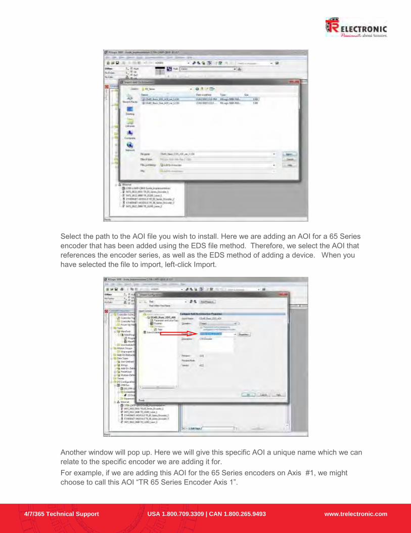
Select the path to the AOI file you wish to install. Here we are adding an AOI for a 65 Series encoder that has been added using the EDS file method. Therefore, we select the AOI that references the encoder series, as well as the EDS method of adding a device. When you have selected the file to import, left-click Import.
Another window will pop up. Here we will give this specific AOI a unique name which we can relate to the specific encoder we are adding it for. For example, if we are adding this AOI for the 65 Series encoders on Axis #1, we might choose to call this AOI “TR 65 Series Encoder Axis 1”.

4/7/365 Technical Support USA 1.800.709.3309 | CAN 1.800.265.9493 www.trelectronic.com
The AOI will get added to your ladder logic so it is important to be able to distinguish one AOI function block from another. When finished re-naming, click “ok”. Notice the addition of the AOI under the Add-On-Instruction folder in the project tree. Our next task is to ensure that the data type of the encoder will be referenced to. This box highlights the data type “code” that will be used. Highlight this number and copy it (Ctrl + C keyboard shortcut). If you are having trouble locating this data type, it is found under “controller tags” in the project tree/controller organizer.
Next, Click on the “Parameters & Local Tags” heading under the Add-On-Instruction folders in the controller organizer. Under the Device Name row, notice the Data Type. Select the “…” box and a new window will open with many data types in it. Here we will need to confirm or ensure the data type from our device that we previously coped, matches the data type we select in this window.
. 1
. 2 . 3
4/7/365 Technical Support USA 1.800.709.3309 | CAN 1.800.265.9493 www.trelectronic.com
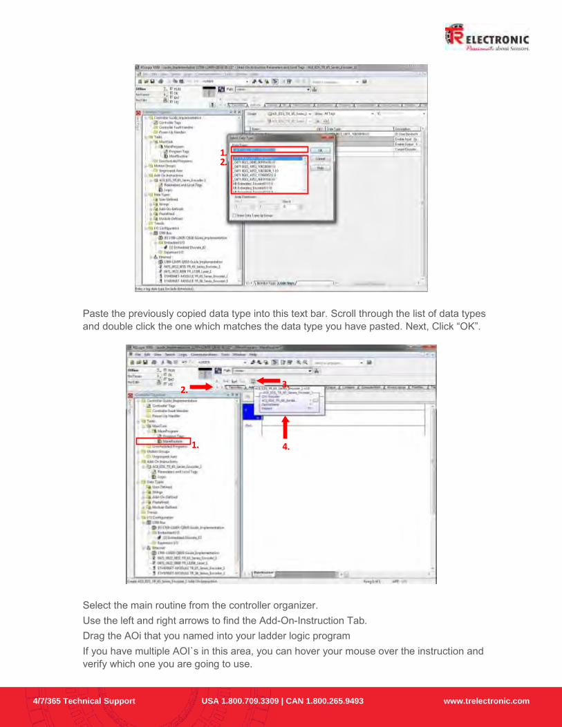
Paste the previously copied data type into this text bar. Scroll through the list of data types and double click the one which matches the data type you have pasted. Next, Click “OK”.
Select the main routine from the controller organizer. Use the left and right arrows to find the Add-On-Instruction Tab. Drag the AOi that you named into your ladder logic program If you have multiple AOI`s in this area, you can hover your mouse over the instruction and verify which one you are going to use.
. 1
. 2 . 3
. 4
1 . 2 .

4/7/365 Technical Support USA 1.800.709.3309 | CAN 1.800.265.9493 www.trelectronic.com
Once the instruction is added to the ladder, an AOI variable will need to be allocated to store the AOI information into memory location. Left-click the box beside the AOI name, then right-click and selct the New Tag option.
There may also be a name already listed with “New” beside it. Click this instead.

4/7/365 Technical Support USA 1.800.709.3309 | CAN 1.800.265.9493 www.trelectronic.com
Define the name of the tag which will be associated with this AOI. Click “Create” when done.
Now that we have defined a tag for the instruction and it has been allocated to the PLC memory, we must now define what device that instruction is going to reference. Under the “DeviceName” heading, click the down arrow and you will see a new window open which has devices available to choose. Double-Click the device which the AOI is going to reference.

4/7/365 Technical Support USA 1.800.709.3309 | CAN 1.800.265.9493 www.trelectronic.com
The AOI is now configured, installed and awaiting use. To see the data that can used, click “Program Tags”. Look for the name of your AOI and expand the tree.
5. BOOTP/DHCP SETUP GUIDE
The following procedure will allow you to assign an IP address to your device, regardless of what address the unit was previously assigned. This is also valid for the assignment of addresses to new devices.
Prerequisite
DHCP server utility from Rockwell Automation (free of charge):
Program name: BootP DHCP EtherNet/IP Tool – Download at: Rockwell Automation website.
If the Rockwell control system "Logix" is used, the BOOTP/DHCP server utility is a
component of the control software.
The program is suitable for the installation on a PC with WINDOWS® operating system. DHCP server and measuring system must be located in the same network segment.
Procedure
A. Connect Measuring system with the DHCP Server
Hardware Switches = 0xFF
Instance Attribute 0x03 Configuration Control = 0x00 00 00 02 (Default Adjustment)

4/7/365 Technical Support USA 1.800.709.3309 | CAN 1.800.265.9493 www.trelectronic.com
B. Start the BootP DHCP EtherNet/IP Tool *Ensure the latest version is being used*
C. Click Tools Network Settings
D. Enter following information:
Subnet Mask: Enter desired subnet
mask
Gateway: Enter desired IP address
of the default Gateway
Primary DNS, Secondary DNS,
Domain Name: Not Supported
E. Use one of the below methods to change IP address, based on whether you know the
current IP address of the device or not.
5.1 LE200 AND 65 SERIES ENCODERS
5.1.1 Using a known IP address
1. Ping current IP Address
2. In the BootP/DHCP software, click “Add Relation” and enter MAC address & original IP address
4/7/365 Technical Support USA 1.800.709.3309 | CAN 1.800.265.9493 www.trelectronic.com
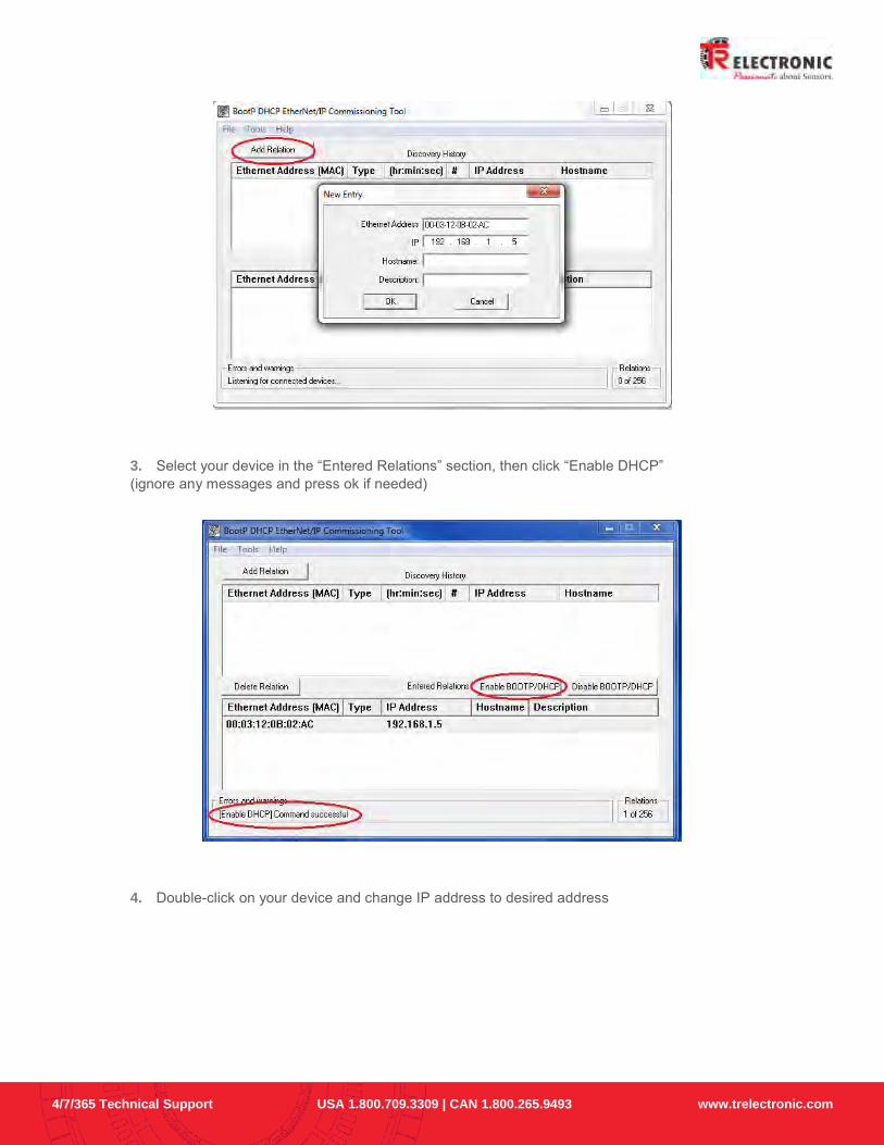
3. Select your device in the “Entered Relations” section, then click “Enable DHCP” (ignore any messages and press ok if needed)
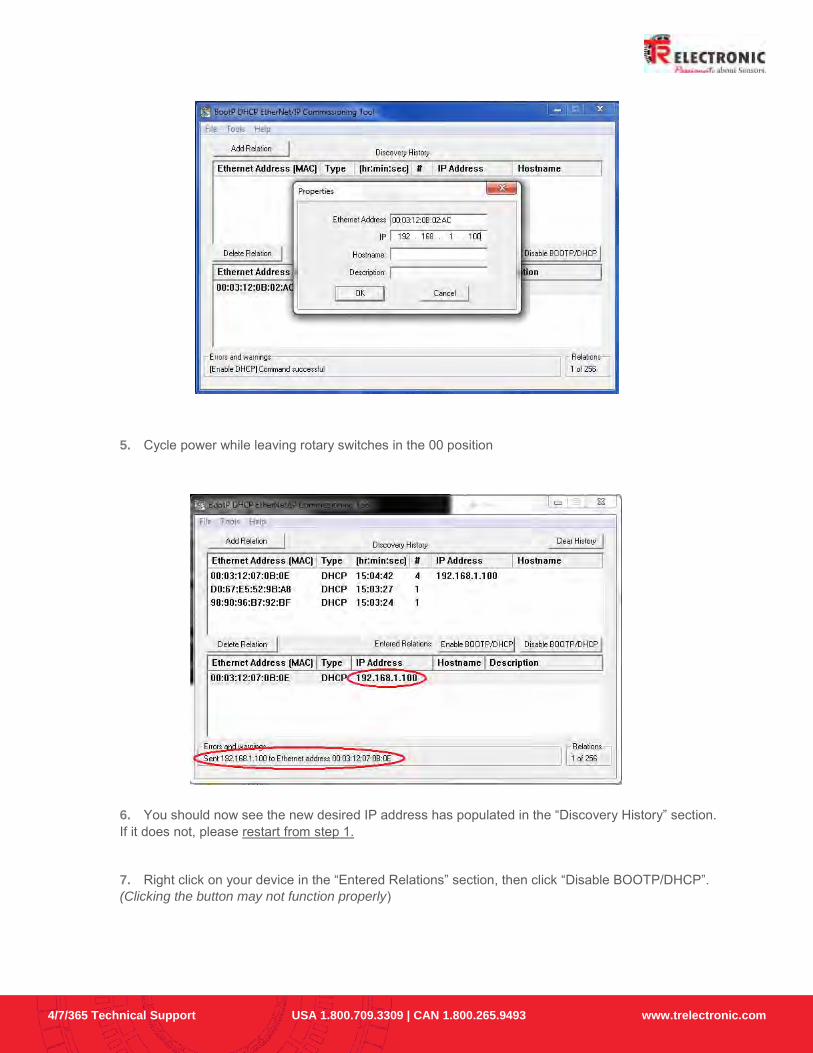
4. Double-click on your device and change IP address to desired address
4/7/365 Technical Support USA 1.800.709.3309 | CAN 1.800.265.9493 www.trelectronic.com
5. Cycle power while leaving rotary switches in the 00 position
6. You should now see the new desired IP address has populated in the “Discovery History” section. If it does not, please restart from step 1.
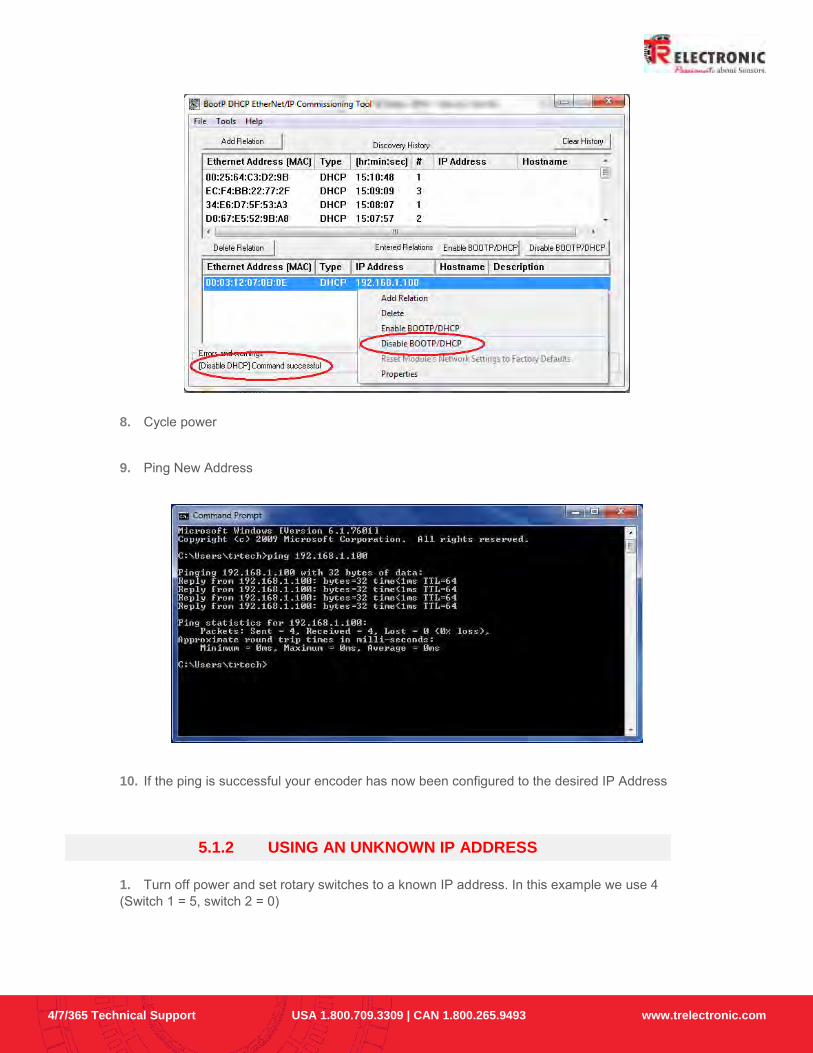
7. Right click on your device in the “Entered Relations” section, then click “Disable BOOTP/DHCP”. (Clicking the button may not function properly)
4/7/365 Technical Support USA 1.800.709.3309 | CAN 1.800.265.9493 www.trelectronic.com
8. Cycle power
9. Ping New Address
10. If the ping is successful your encoder has now been configured to the desired IP Address
5.1.2 USING AN UNKNOWN IP ADDRESS
1. Turn off power and set rotary switches to a known IP address. In this example we use 4 (Switch 1 = 5, switch 2 = 0)

4/7/365 Technical Support USA 1.800.709.3309 | CAN 1.800.265.9493 www.trelectronic.com
2. Power up device and attempt to ping new IP address (192.168.1.5)
3. In BOOTP software, click “Add Relation” and enter MAC address and IP address

4/7/365 Technical Support USA 1.800.709.3309 | CAN 1.800.265.9493 www.trelectronic.com
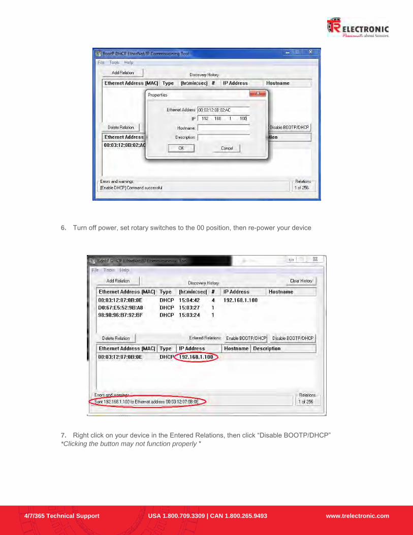
4. Select your device in the “Entered Relations” section, then click “Enable BOOTP/DHCP” (Ignore any messages and press ok if needed) 5. Within the “Entered Relations” section, double-click on your device and enter the desired IP address
4/7/365 Technical Support USA 1.800.709.3309 | CAN 1.800.265.9493 www.trelectronic.com
6. Turn off power, set rotary switches to the 00 position, then re-power your device
7. Right click on your device in the Entered Relations, then click “Disable BOOTP/DHCP” *Clicking the button may not function properly *

4/7/365 Technical Support USA 1.800.709.3309 | CAN 1.800.265.9493 www.trelectronic.com
8. Cycle power
9. Ping new address
10. If the ping is successful your encoder has now been configured to the desired address

4/7/365 Technical Support USA 1.800.709.3309 | CAN 1.800.265.9493 www.trelectronic.com
5.2 58 SERIES ENCODERS 1. Turn off power and set the rotary switches to FF
2. Open BootP-DHCP Software Tool and re-apply power to the encoder
3. Unit should appear in “Discovery History” section. If nothing appears after 10 seconds, try cycling power to the encoder
4. Double-click the device that corresponds with your encoders MAC address and set the desired IP

4/7/365 Technical Support USA 1.800.709.3309 | CAN 1.800.265.9493 www.trelectronic.com
5. Your desired IP address should now show on your device in the “Discovery History” section (if it does not, cycle power)
6. Once your device info matches in both the “Discovery History” and the “Relations List” sections, disable DHCP by right clicking the device and selecting “Disable DHCP”. Under Errors and warnings it will tell you that the disable was successful

4/7/365 Technical Support USA 1.800.709.3309 | CAN 1.800.265.9493 www.trelectronic.com
7. Power off the encoder and set the rotary switches to 00
8. Power on the encoder and ping the new IP address to verify the change was made

4/7/365 Technical Support USA 1.800.709.3309 | CAN 1.800.265.9493 www.trelectronic.com
NOTES:

TR Electronic Center of Technical Excellence will work with you to develop the best solution for your Application.
|
USA 1.800.709.3309 CAN 1.800.265.9493