Embed Size (px)
DESCRIPTION
Fire protection design of aircraft hangers for Air Force government projects. Currently under revision.
Citation preview
DEPARTMENT OF THE AIR FORCEHEADQUARTERS AIR FORCE CIVIL ENGINEER SUPPORT AGENCY
DEC 3 2002
APPROVED FOR PUBLIC RELEASE: DISTRIBUTION UNLIMITED
FROM: HQ AFCESA/CES139 Barnes Drive, Suite 1Tyndall AFB, FL 32403-5319
SUBJECT: Engineering Technical Letter (ETL) 02-15: Fire ProtectionEngineering Criteria - New Aircraft Facilities
1. Purpose. This ETL provides fire protection criteria for protection of aircraft andfacilities in the event of a fuel spill fire. Human intervention is required to minimizedamage to incident aircraft.
2. Summary of Revisions. This ETL supersedes ETL 01-2, and includes the followingchanges: Deleted references to semi-hardened and hardened aircraft shelter nowcovered in ETL 01-4 (paragraph 3); clarified the aircraft type covered (paragraph 3.5);changed MIL-HDBK 1008C to UFC 3-600-01 (paragraph 4.3 and throughout the ETL);changed the UBC to the IBC (paragraph 4.8 and throughout the ETL); included thecomplete title and source for the Air Force Standard Design Details (paragraph 6 Note);clarified the requirements for electrical systems (paragraph A1.1.2.3.4); clarified therequirements for fire hydrants in or near airfield pavements (paragraph A1.1.2.4.2);included the use of stabilized landscaped surfaces (paragraph A1.2.1); clarified themeaning of unfueled aircraft (paragraph A1.3.1.1.1); revised the compensation factorfor foam leakage loss (paragraph A1.3.3.3); added a note cautioning the designer toconsider all transit voltage sources (paragraph A1.3.5.1.2.1 Note); added arequirement for locking manual stations (paragraph A1.3.5.5.1); added specific wordingto place manual stations on a sign (paragraph A1.3.5.5.2); revised the graphic of thesign (Figure A5); clarified water source requirements (paragraphs A1.4.1 and A1.4.1.2);and added Figure A2.5 to Attachment 2.
3. Application: All types of aircraft facilities, including, but not limited to,maintenance, servicing, and storage hangars; corrosion control hangars; fuel cell repairhangars; depot overhaul facilities; research and development (R&D)/testing facilitieshousing aircraft; and all types of aircraft shelters (weather, alert). Compliance with thisETL should be considered for projects in active design beyond project definition (PD).Applying these criteria will result in reduced original construction and life-cyclemaintenance costs, and increased overall reliability of the fire protection system.Compliance with this ETL is mandatory for:
• Projects that have not completed the PD phase.• Projects beyond the PD phase, but not in active design status.

3.1. New Construction. Criteria within this ETL applies to the design and constructionof all new aircraft facilities on Air Force installations or housing Air Force aircraft.
3.2. Existing Facilities. Criteria within this ETL applies to the design and constructionof fire protection features for all existing aircraft facilities without installed firesuppression systems. Renovation, modification, or alteration of existing aircraft facilitieswithout installed fire suppression systems will comply with the criteria contained in thisETL.
3.3. Occupancy Changes. Use of this ETL is mandatory during a major occupancychange, such as converting a former hangar currently being used as a warehouse backto an aircraft hangar. Change of aircraft does not constitute a change of occupancy;however, beddown of a new mission is not recommended in an existing hangar withouta fire suppression system.
3.4. Integrated Combat Turn (ICT) Facilities. Criteria within this ETL apply to facilitiesfor ICTs; however, compliance with this ETL is not authorization to conduct ICTs. ICTlocations must be specifically evaluated and approved through the System SafetyEngineering Program (AFI 91-202, The US Air Force Mishap Prevention Program).
3.5. Other Facilities. Facilities used exclusively for small aircraft (T-3, T-41, TG-3,TG-4, TG-7, TG-9, S-10), aero club aircraft, and similar aircraft within the sizelimitations for Group III hangars in National Fire Protection Association (NFPA) 409,Standard on Aircraft Hangars, will be protected with a fire suppression systemcomplying with paragraph A1.3.1.1.4 and the other requirements of either NFPA 409 forGroup III aircraft hangars or the requirements of this ETL. Mission aircraft such as T-1,T-6, T-37, T-38, and similar aircraft will be protected in accordance with therequirements of this ETL (paragraph A1.3.1.1.4 will not apply to these facilities).
3.6. Excluded Facilities. The following facilities are not addressed in this ETL:• Aircraft shelters with two or fewer sides (including partial walls). These
shelters will be treated as open ramps.• Existing aircraft facilities with fire suppression systems in aircraft servicing
areas. Fire protection modification/upgrade requirements will be addressed ina separate ETL.
• Protective aircraft shelters (PAS), hardened aircraft shelters (HAS), and semi-hardened aircraft shelters (HAS). These facilities are designed to provide adegree of survivability under combat conditions and or enemy attack. Refer toETL 01-4.
3.7. Authority: AFI 32-1023, Design and Construction Standards and Execution ofFacility Construction Projects.
3.8. Effective Date: Immediately.

3.9. Recipients: All major commands (MAJCOM) and Air Force activities.
3.10. Coordination: HQ USAF/ILEC, MAJCOM fire protection engineers, HQ NAVFAC,and USACE/CECP-TM.
Note: Criteria in this ETL assume fire department capabilities consistent withAFI 32-2001, The Fire Protection Operations and Fire Prevention Program, and a watersupply and fire hydrant configuration at the hangar to support firefighting. Use of thesecriteria at other locations is not recommended without a complete risk analysisprepared by the base (or the project architect-engineer [A-E] for new construction) andaccepted by the MAJCOM fire protection engineer (FPE) and the MAJCOM firedepartment operations (FDO) group.
4. Referenced Publications.
4.1. Air Force:• AFI 32-1066, Plumbing Systems• AFH(I) 32-1163, Engineering Weather Data• AFI 32-2001, The Fire Protection Operations and Fire Prevention Program• AFI 91-202, The US Air Force Mishap Prevention Program• Technical Order 1-1-3, Inspection and Repair of Aircraft Integral Tank and
Fuel Cells
4.2. U.S. Army Corps of Engineers (USACE):• Engineer Technical Letter 1110-3-484, Engineering and Design – Aircraft
Hangar Fire Protection Systems
4.3. Department of Defense (DOD):• UFC 3-600-01, Fire Protection for Facilities Engineering, Design, and
Construction
4.4. National Fire Protection Association (NFPA):
Note: The latest edition of an NFPA standard applies.• NFPA 11A, Standard for Medium- and High-Expansion Foam Systems• NFPA 13, Installation of Sprinkler Systems• NFPA 20, Standard for the Installation of Stationary Fire Pumps for Fire
Protection• NFPA 24, Installation of Private Fire Service Mains and their Appurtenances• NFPA 30, Flammable and Combustible Liquids Code• NFPA 31, Standard for the Installation of Oil-Burning Equipment• NFPA 33, Standard for Spray Application Using Flammable or Combustible
Materials

• NFPA 34, Standard for Dipping and Coating Processes Using Flammable orCombustible Liquids
• NFPA 54, National Fuel Gas Code• NFPA 70, National Electrical Code
• NFPA 72, National Fire Alarm Code
• NFPA 90A, Standard for the Installation of Air Conditioning and VentilatingSystems
• NFPA 101, Life Safety Code• NFPA 409, Standard on Aircraft Hangars
4.5. American Society for Testing and Materials (ASTM):• ASTM A53, Standard Specification for Pipe, Steel, Black and Hot-Dipped,
Zinc-Coated, Welded and Seamless• ASTM A795, Standard Specification for Black and Hot-Dipped Zinc-Coated
(Galvanized) Welded and Seamless Steel Pipe for Fire Protection Use• ASTM D2996, Standard Specification for Filament-Wound “Fiberglass” (Glass-
Fiber-Reinforced Thermosetting-Resin) Pipe
4.6. American National Standards Institute (ANSI):• ASME/ANSI A13.1-1996, Scheme for the Identification of Piping Systems• ASME/ANSI B31.3-1996, Process Piping
4.7. Underwriter’s Laboratories (UL):• UL 1449, Standard for Safety Transient Voltage Surge Suppressors, Second
Edition• UL 1283, Electromagnetic Interference Filters, latest edition
4.8. Private Industry:• Factory Mutual (FM) Global Property Loss Prevention Data Sheet 1-22,
Criteria for Maximum Foreseeable Loss Fire Walls and Space Separation• FM Global Property Loss Prevention Data Sheet 1-23, Protection of Openings• International Code Council, International Building Code (IBC) 2000
5. Acronyms and Terms:
AC – alternating currentA-E – architect-engineerAFFF – aqueous film forming foamDOD – Department of DefenseETL – Engineering Technical LetterFACP – fire alarm control panelFDO – Fire Department OperationsFPE – Fire Protection EngineerFSCP – foam system control panelft2 – square footft3 – cubic foot
gpm – gallons per minuteHAS – hardened aircraft shelterHVAC – heating, ventilation, and air conditioningICT – integrated combat turnILBP – in-line balanced pressurekPa – kiloPascalslpm – liters per minutem2 – square meterm3 – cubic meterMAJCOM – major commandMILCON – military constructionNAVFACENGCOM – Naval Facilities Engineering CommandNCEE – National Council of Examiners for Engineering and SurveysNDI – non-destructive inspectionNEC – National Electrical CodeNFPA – National Fire Protection StandardOSHA – Occupational Safety and Health AdministrationPAS – protective aircraft shelterPD – project definitionPE – Professional Engineerpsi – pound per square inchR&D – research and developmentHAS – hardened or semi-hardened aircraft shelterSIOH – supervision, inspection, and overheadT.O. – Technical OrderTVSS – transient voltage surge suppressionIBC – Uniform Building CodeUL – Underwriters LaboratoriesUSACE – U.S. Army Corps of EngineersUV/IR – ultraviolet/infraredV – voltVac – volts alternating current
6. Specific Requirements. This ETL, in accordance with UFC 3-600-01, FireProtection for Facilities Engineering, Design, and Construction, paragraph 1-3.4, takesprecedence over UFC 3-600-01, section 4-15. This ETL is the Air Force alternative toNFPA Standard 409, and will be used except as noted. Attachment 1 provides criteriaand technical guidance.
Note: Aircraft Hangar Standards. All design and construction packages will use the AirForce aircraft hangar standardized design details, Aircraft Hangar Fire ProtectionSystems, Standard Design Elements, CAD Drawings and Specifications Version2001.01 1 July 2001 (available from Mr. Fred Walker; refer to paragraph 7 for contactinformation).
6.1. U.S. Army Corps of Engineers (USACE) Center of Expertise for Aircraft HangarFire Protection.

Note: Services of the Center of Expertise are provided on a cost reimbursable basisbetween the USACE district designing and constructing the project and USACE. Thisservice is expected to be covered in the standard design management fee, andsupervision, inspection, and overhead (SIOH) paid on the project. This service shouldnot result in additional costs or fees to the project.
6.1.1. For all hangar military construction (MILCON) projects on which USACE is thedesign agent, the USACE Center of Expertise will review all project designs to ensurecompliance with this ETL. This review is mandatory at all design review stages, and allformal review comments issued by the Center of Expertise will be implemented to thesatisfaction of the Air Force in accordance with USACE Engineer Technical Letter1110-3-484, Engineering and Design – Aircraft Hangar Fire Protection Systems.
6.1.2. For all hangar MILCON projects on which USACE is the construction agent, theCenter of Expertise will review all contractor shop submittals to ensure compliance withthis ETL. All review comments issued by the Center of Expertise will be implemented bythe USACE contracting officer to the satisfaction of the Air Force. An FPE at the Centerof Expertise will perform the final acceptance testing of all hangar fire protectionsystems. The MILCON project will not be accepted by the USACE contracting officeruntil the Center of Expertise has accepted the fire protection systems.
6.3. Naval Facilities Engineering Command (NAVFACENGCOM) Division FPE.
6.3.1. For all hangar MILCON projects on which NAVFACENGCOM is the designagent, the division FPE will review all project designs to ensure compliance with thisETL. This review is mandatory at all design review stages, and all formal reviewcomments issued will be implemented to the satisfaction of the Air Force.
6.3.2. For all hangar MILCON projects, the division FPE will review all contractor shopsubmittals to ensure compliance with this ETL. The contracting officer will implement allreview comments to the satisfaction of the Air Force. An FPE will perform the finalacceptance testing of all hangar fire protection systems.
7. Point of Contact. Fire protection criteria for aircraft facilities must evolveconcurrently with technical developments in fire science, data generated in fire testingprograms, and the availability of new fire protection equipment or methodologies.Recommendations for improvements to this ETL are encouraged and should befurnished to Mr. Fred Walker, HQ AFCESA/CESM, 139 Barnes Drive, Suite 1, TyndallAFB, FL 32408-5319, DSN 523-6315, commercial (850) 283-6315, FAX DSN 523-6219, Internet: [email protected].

MICHAEL J. COOK, Colonel, USAF 3 AtchsTechnical Director 1. Technical Criteria
2. Low-Level High-Expansion FoamSystem Views
3. Distribution List

Atch 1(1 of 28)
TECHNICAL CRITERIAAIR FORCE AIRCRAFT HANGAR FIRE PROTECTION
A1.1. Construction Requirements.
A1.1.1. Structural Requirements. All new aircraft hangars will be exclusivelynoncombustible construction in accordance with the International Code Council,International Building Code 2000 (IBC) requirements for any category of Type I orType II construction.
Note: Additional protection of structural members (columns, beams, trusses, joists)above that established in the IBC for Type I or Type II construction is not required in afacility protected by an approved fire suppression system in compliance with this ETL.
A1.1.1.1. Exceptions:
A1.1.1.1.1. Tension fabric structures on metal structural frames when sited inaccordance with paragraph A1.1.1.4.3 and protected in accordance with paragraph A3.
A1.1.1.1.2. Facilities used exclusively for small aircraft (T-3, T-41, TG-3, TG-4, TG-7,TG-9, S-10), aero club aircraft, and similar aircraft meeting the space requirements ofNFPA 409 for Group III structures. These facilities must comply with criteria in NFPA409 for Group III hangars and paragraph A1.3.1.1.4.
A1.1.1.2. Internal Fire-Rated Separations. To allow the greatest operational flexibilityin hangars covered by this ETL, fire-rated walls and partitions are not required betweenadjacent aircraft servicing areas when the nature of the occupancy is similar in bothbays. Operations such as fuel cell maintenance, ICT, and indoor refueling must beseparated from general maintenance areas by walls of masonry construction, havingnot less than a one-hour fire rating with 45-minute opening protection. Such walls willextend from the floor to the underside of the roof deck.
A1.1.1.2.1. All operations outside the aircraft servicing area must be isolated from theaircraft servicing area by a masonry wall having a fire resistance rating of at least onehour. This wall will extend from the concrete floor to the roof. All openings in this wallwill be automatic closing or self-closing and will be rated for at least 45 minutes. Theseareas outside the aircraft servicing area must have full sprinkler coverage inaccordance with this ETL.
A1.1.1.2.2. Air Force operational aircraft assets will be isolated from the non-Department of Defense (DOD) areas by four-hour rated firewalls when Air Force aircraftassets are co-located in a facility with non-DOD operations that are beyond the controlof the DOD activity. Penetrations of such firewalls must be minimized. Any necessarydoor, window, and other penetration must be protected in accordance with Factory
Atch 1(2 of 28)
Mutual Global Property Loss Prevention Data Sheets 1-22, Criteria for MaximumForeseeable Loss Fire Walls and Space Separation, and 1-23, Protection of Openings.
A1.1.1.3. Allowable Floor Area.
A1.1.1.3.1. The allowable floor area of a facility is unlimited when all of the followingconditions are met:
• 100 percent of the facility has full sprinkler coverage in accordance withthis ETL.
• Water supply to the sprinkler systems is in compliance with the criteria inthis ETL.
• Separations from adjacent structures complies with paragraphs A1.1.4.through A1.1.4.3.
• Internal separation walls comply with paragraph A1.1.1.2.
A1.1.1.3.2. Facilities not meeting the conditions in paragraph A1.1.1.3.1 will be limitedto the floor areas contained in the latest edition of the IBC for occupancy type S-1,except facilities used for fuel cell maintenance, ICT, or indoor refueling/defueling, whichwill be occupancy type H-3.
A1.1.1.4. Siting/Separation. No separation is required between any combination ofType I or Type II construction hangars protected by approved fire suppression systems.
A1.1.1.4.1. Separation Between Type I and Type II Hangars and Hangars of OtherConstruction Types. The minimum separation distance between adjacent hangars is 12meters (40 feet). This may be reduced to 7.6 meters (25 feet) if one of the hangars hasa one-hour exposure wall and protected 45-minute openings (e.g., windows, doors), orif both hangars have approved fire suppression systems. This may be further reducedto 3 meters (10 feet) if both hangars have one-hour exposure walls and protected 45-minute openings.
A1.1.1.4.2. Separation Between Hangars and Other Buildings. Minimum separationbetween hangars and other buildings is 12 meters. Reductions in this distance mustconform to the IBC.
A1.1.1.4.3. Separation Between Tension Fabric Hangars and All Other Structures.Minimum separation between tension fabric structures and other structures will be 30meters (100 feet), with a clear zone of 15 meters (50 feet) immediately adjacent to thetension fabric structure. The clear zone cannot be used for storage and must be clearof vegetation (maintained lawn is permitted). The clear zone may be used as a street ordriveway, but not for vehicle parking.
A1.1.1.5. Draft Curtains.
Atch 1(3 of 28)
A1.1.1.5.1. Provide draft curtains surrounding each sprinkler system, or up to 1400square meters (15,000 square feet), whichever is less, for all hangars. Extend draftcurtains down from the roof (or ceiling) not less than one-eighth of the distance fromthe roof (or ceiling) to the floor. When roof structural supports extend below the roof orceiling, suspend draft curtains to the lowest member of the structural supports, or one-eighth the distance from the roof or ceiling, whichever is greater.
A1.1.1.5.2. Install draft curtains to form rectangular roof pockets whenever possible.Install draft stops on exposed structural roof supports whenever possible.
A1.1.2. Utility Systems.
A1.1.2.1. Floor and Ramp Drainage.
A1.1.2.1.1. Outside the Hangar. Aprons and the approach into the hangar must besloped away from the hangar with a grade of not less than one-half of one percent(0.3:60 meters [1:200 feet]) to preclude a ramp fuel spill from entering. If the requiredgrade cannot be achieved, provide an appropriately sized trench drain across theentire apron side of the hangar with a discharge to a remote safe location.
A1.1.2.1.2. Inside the Hangar. Floor elevations within the hangar must be arranged toprevent a liquid spill within the aircraft servicing area from flowing into adjacent areas.
A1.1.2.2. HVAC Systems.
A1.1.2.2.1. Install heating equipment in accordance with NFPA 90A, Standard for theInstallation of Air Conditioning and Ventilating Systems; NFPA 31, Standard for theInstallation of Oil-Burning Equipment; or NFPA 54, National Fuel Gas Code and thissection.
A1.1.2.2.2. Heating devices with a flame or glowing element open to the atmosphere inthe aircraft servicing area are not permitted.
A1.1.2.2.3. Where radiant heating is used, install only overhead radiant tube systems.
A1.1.2.2.4. Forced- or recirculated-air HVAC systems will not draw air from the aircraftservicing area below 3 meters (10 feet).
A1.1.2.2.5. Exhaust systems discharging to the exterior of the facility may draw air atany level.
A1.1.2.3. Electrical Systems.
A1.1.2.3.1. Install electrical equipment in general maintenance aircraft hangars inaccordance with NFPA 70, National Electrical Code (NEC), Article 513.
Atch 1(4 of 28)
Note: Most operational aircraft use on-board fuel for a heat sink/dissipater. Manyhangar maintenance activities, including avionics and hydraulic operations, will causeheating of the fuel on these aircraft. Fuel temperatures above 71 °C (160 °F) areoperationally acceptable; therefore, NFPA 70, Article 513 requirements for combustiblefuel above its flash point must be followed.
A1.1.2.3.2. Install electrical equipment in hangars for fuel system maintenanceoperations involving combustible fuels, including JP-8, in accordance with NFPA 70,Article 513, for flammable fuels or combustible fuels above their flash point.
Note: Technical Order (T.O.) 1-1-3, Inspection and Repair of Aircraft Integral Tank andFuel Cells, additionally requires all outlets in the aircraft servicing area to be Class IDivision 2 rated. This is an aircraft maintenance (user) safety requirement, not a firesafety issue. Additional information on this requirement is available from the commandfuels system maintenance office or the T.O. manager at Warner Robins Air LogisticsCenter.
A1.1.2.3.3. Install electrical equipment in hangars with the following operations inaccordance with paragraphs A1.1.2.3.3.1 and A1.1.2.3.3.2:
• Refueling or defueling, regardless of fuel type (other than that associatedwith fuel system maintenance).
• ICTs, regardless of fuel type.• Fuel system maintenance operations with flammable fuels.
A1.1.2.3.3.1. Electrical equipment above the floor in the aircraft servicing area up tothe height of the highest hangar door must satisfy NEC criteria for Class I Division 2locations.
A1.1.2.3.3.2. Electrical equipment outside the classified area in the aircraftmaintenance area, including lights, must conform to NFPA 70, Article 513.
A1.1.2.3.4. In hangars where the rate of spray paint application exceeds 0.9 liter(1 quart) per hour, or the cumulative application of more than 3.7 liters (1 gallon) overan eight-hour period, install Class I Division 1 or Class I Zone 1 electrical equipmentthroughout in accordance with NFPA 33, Spray Applications Using Flammable orCombustible Materials, for an enclosed spray room or booth. Spray area definitions donot apply to aircraft hangars constructed as painting facilities. Installed overheadmounted moveable platforms must be individually evaluated, but all controls, switches,and motors must be Class I Division 1 or Class I Zone 1.
A1.1.2.4. Fire Hydrants.
A1.1.2.4.1. Hydrants protecting aircraft hangars will be located at 91-meter (300-foot)maximum intervals, and there will be at least one hydrant within 30 meters of each

Atch 1(5 of 28)
corner of the hangar. When the aircraft parking apron pavement comes within 11meters (35 feet) or less of the hangar wall at the hydrant location, the hydrantsprotecting hangars will be located not more than 3 meters from the hangar wall. Whenthe aircraft parking apron pavement is 11 meters or more away from the hangar wall atthe hydrant location, the hydrants protecting hangars will be located not less than7.6 meters from the pavement edge.
A1.1.2.4.2. Hydrants installed through the airfield pavement must be low-profile,conventional hydrants, not higher than 0.7 meter (2.5 feet) above the pavementsurface. Flush-mounted hydrants in the pavement are not permitted.
A1.1.2.4.3. Hydrants installed in unpaved areas adjacent to the airfield pavement mustbe no higher than 0.7 meter (2.5 feet) above the pavement surface.
A1.1.2.4.4. Hose threads on hydrants must match those used by the base firedepartment.
A1.1.2.4.5. Fire hydrants will be supplied from the domestic (potable) water systemaround the hangar in accordance with UFC 3-600-01, Section 3-7.3. Install water mainssupplying hydrants in accordance with UFC 3-600-01. Hydrants will not be supplied bythe hangar fire protection water system.
A1.1.2.5. Foam-Water Retention Systems. Retention systems are not required forfacilities or systems designed and constructed in accordance with this ETL. Foam-water retention is not required in any of the following cases:
• Testing discharges of any systems discussed in this ETL (testheaders/connections are required on all new foam-water systems allowingcontrolled discharge into a tank or other portable collection device, so nofixed permanent retention capability is required). In geographic regionswhere there is little or no open water, streams, or wetlands, and no high-ground water table (solar evaporation is an appropriate disposal method).
• Low-level high-expansion foam systems, since the highly expanded foamcontains little liquid and is impractical to control.
• Catastrophic events, such as actual fires. Foam discharge associated witha fire is not a “most probable worst case” event. A fire in a hangar is acatastrophic event. Designing a containment system for a catastrophicevent is impractical due to the number of associated variables and themass of fire debris generated.
A1.1.2.5.1. Unplanned Accidental Events. Current environmental guidance formanagement of unplanned accidental foam discharges:
• Formally documented response plan by the installation spill team and/oroff-base contractors to contain, collect, and dispose of discharged foam.

Atch 1(6 of 28)
• Direct release to a government-operated sanitary or industrial wastetreatment facility, if the foam-water solution is less than 50 parts per millionof the plant influent.
• In geographic regions where there is little or no open water, streams, orwetlands, and no high-ground water table, solar evaporation is anappropriate disposal method.
A1.1.2.5.2. Other Retention Issues. For additional guidance or information on foamretention and management, consult with HQ USAF/ILEV and or MAJCOM/CEV.
A1.2. Accessibility for Firefighting:
A1.2.1. Exterior Firefighting. Provide fire apparatus access on at least two completesides of every hangar. Suitable access surfaces include ramps, aircraft parking aprons,automotive parking areas, fire apparatus access roads, and stabilized landscapedareas.
A1.2.1.1. Automotive parking areas used for fire department access must include atleast one aisle 5.4 meters (18 feet) wide, with adequate turning radius for firedepartment apparatus.
A1.2.1.2. Fire department access roads must be at least 5.4 meters wide, designed tosupport imposed loads of fire apparatus, and provide all-weather driving capabilities.Where mowed lawns cover fire department access roads, use bollards to mark thelimits of the supporting surface. Fire department access roads over 45 meters (150feet) long must allow fire apparatus to drive through or turn around. Fire departmentaccess roads must not be used for any other purpose, and should be secured withgates, bollards, or similar devices to restrict use.
A1.2.2. Interior Firefighting.
A1.2.2.1. Hangar aircraft doors must operate under emergency conditions.
A1.2.2.1.1. Configure hangar doors for manual operation without special tools ordisassembly.
A1.2.2.1.2. Use door track heaters in areas subject to freezing to prevent accumulatedsnow and ice from impeding operation of hangar doors.
A1.2.2.1.3. The electrical supply for power-operated doors must be independent of thebuilding power supply to permit isolation of power to the facility during a fire withoutinterrupting power to door motors.
A1.2.2.1.4. Provide a key-operated or other access-controlled switch on the exterior ofthe facility for operation of power-operated doors.

Atch 1(7 of 28)
A1.2.2.2. Personnel doors satisfying requirements of the Life Safety Code, IndustrialOccupancies chapter, Special Provisions for Aircraft Servicing Hangars section(NFPA 101, Life Safety Code), will provide adequate access into the hangar fornormal structural firefighting operations.
A1.3. Fire Suppression Systems.
A1.3.1. General Requirements.
A1.3.1.1. Applicable Design Standards and Criteria. Provide automatic sprinklerprotection in all areas of aircraft facilities, including shop and administration. Sprinklerprotection must be designed for the occupancy hazard present in accordance with thisETL, UFC 3-600-01, NFPA 33, and the following NFPA standards (if there is a conflictbetween this ETL and any provisions of an NFPA standard or code, this ETL will takeprecedence):
• NFPA 13, Installation of Sprinkler Systems• NFPA 30, Flammable and Combustible Liquids Code• NFPA 34, Standard for Dipping and Coating Processes Using Flammable or
Combustible Liquids
A1.3.1.1.1. Protect areas used exclusively for unfueled aircraft (drained and purged inaccordance with T.O. 1-1-3) with conventional wet-pipe sprinkler systems designed forOrdinary Hazard Group 2 occupancy (8.0 lpm/m2 over 270 square meters [0.2 gpm/ft2
over 3000 square feet]).
Note: An unfueled aircraft is not one which has been simply defueled; defueled aircraftare considered fueled aircraft for the purposes of fire protection safety. An unfueledaircraft has had fuel removed from all tanks, engines and piping such that less than0.5% of fuel remains in the aircraft (using the procedures in T.O. 1-1-3).
A1.3.1.1.2. Protect areas used for fueled aircraft with a conventional wet-pipe sprinklersystem (8.0 lpm/m2 over 465 square meters [0.2 gpm/ft2 over 5000 square feet]) and alow-level high-expansion foam system.
A1.3.1.1.3. Protect dedicated single-aircraft facilities used exclusively for non-destructive inspection (NDI) (e.g., x-raying) of fueled or unfueled aircraft with no aircraftmaintenance or servicing operations with conventional wet-pipe sprinkler systemsdesigned for Extra Hazard Group 1 occupancy (12.0 lpm/m2 over 270 square meters[0.3 gpm/ft2 over 3000 square feet]).
A1.3.1.1.4. Protect NFPA Group III hangars used exclusively for small aircraft (T-3, T-41, TG-3, TG-4, TG-7, TG-9, S-10), aero club aircraft, and similar aircraft withconventional wet-pipe or dry-pipe sprinkler systems designed for Extra Hazard Group 1occupancy (12 lpm/m2 over 270 square meters [0.3 gpm/ft2 over 3000 square feet]).
Atch 1(8 of 28)
A1.3.1.2. Manual Foam-Water/Water Fire Hose Stations. Do not provide interior orexterior hose stations or fire hose connections.
A1.3.1.3. Fire Department Connections. Do not provide fire department connections onfoam-water systems.
A1.3.1.4. Strainers. Provide basket-type strainers upstream of risers on all foam-watersystems.
A1.3.1.5. Test Header. Provide a test header for all overhead and low-level nozzlefoam-water systems. Locate the header inside the aircraft servicing area as near aspracticable to an outside door. Configure the test header to permit each proportioner tobe individually tested. Each test header must have at least four valved 2.5-inch (noequal metric standard) hose fittings.
A1.3.1.6. Underground Piping. Install underground piping systems, including piping infire pump systems, in accordance with NFPA 24, Installation of Private Fire ServiceMains and their Appurtenances, and the following:
A1.3.1.6.1. Provide ductile iron pipe or other pipe (high-density polyethylene orfilament-wound fiberglass) listed by Underwriters Laboratories (UL) or approved byFactory Mutual for buried fire service application for all underground uses.
A1.3.1.6.2. Do not install any piping under hangar/facility floor slabs. If piping must belocated below the floor line, use concrete trenching with open steel grating. Providedrains to sanitary sewer from any trenches. Do not install any piping, including the fireprotection water service entrance into the building, that allows pressurization of thespace below the floor slab. Minimize piping under paved operational surfaces (taxiwaysand aircraft parking).
A1.3.1.6.3. Size underground mains to ensure the maximum flow velocity does notexceed 3 meters per second.
A1.3.1.6.4. Use flanged or welded fittings (Figures A1.1 and A1.2) to transition the fireprotection water service entrance from horizontal to vertical as it enters the building. Donot use gasketed compression fittings (including locking type), or flange fittings withsetscrews.

Atch 1(9 of 28)
HANGAR FOUNDATION
HANGAR FLOOR
TO RISERS
PIV
FINISHED GRADE
ALL WELDED OR FLANGEDCONNECTIONS
HANGAR EXTERIOR WALLFIRE PROTECTIONEQUIPMENT ROOM
FIRE PROTECTIONEQUIPMENT ROOM
HANGAR FOUNDATION
HANGAR FLOOR
TO RISERS
PIV
FINISHED GRADE
ALL WELDED OR FLANGEDCONNECTIONS
HANGAR EXTERIOR WALL
GRATING
Figure A1.1 Water Supply Pipe Entry Figure A1.2 Water Supply Pipe Entry
A1.3.1.6.5. Provide corrosion protection on underground fire mains in the samemanner as required for domestic water and other buried piping at the location.
A1.3.1.6.6. Do not install piping carrying foam concentrate or foam-water solutionunderground.
A1.3.1.7. Backflow Prevention. Install backflow prevention devices at connections todomestic water distribution systems. Backflow prevention is not required in dedicatednon-potable water distribution systems. Valves that are part of a backflow preventionassembly will be the indicating type and will be supervised. Omit post indicator valveswhen backflow preventers are located outside. Locate backflow preventers inside theprotected buildings when freeze protection is required. Do not use heat tapes ortracings to provide freeze protection; however, in locations where simple insulation willprovide adequate freeze protection, the backflow preventer may be located outside(see AFI 32-1066, Plumbing Systems).
A1.3.1.7.1. Connections between potable water systems and systems containingchemical fire suppression agents or additives will use reduced-pressure backflowpreventers.
A1.3.1.7.2. Connections between potable water systems and systems that do notcontain chemicals (e.g., wet pipe systems) will use double-check valve assembliesunless otherwise required by local health and or water authorities.
A1.3.1.7.3. Install backflow prevention on the discharge side of pumps supplieddirectly from domestic water systems.
A1.3.1.8. Interior Piping Systems.
A1.3.1.8.1. Limit maximum flow velocity in interior facility piping to 6 meters per second(20 feet per second) or less.
Atch 1(10 of 28)
A1.3.1.8.2. For water systems, use standard-weight pipe conforming to ASTM A795,Standard Specification for Black and Hot-Dipped Zinc-Coated (Galvanized) Welded andSeamless Steel Pipe for Fire Protection Use, or ASTM A53, Standard Specification forPipe, Steel, Black and Hot-Dipped, Zinc-Coated, Welded and Seamless.
A1.3.1.8.3. For foam-water systems, use one of the following:• Standard-weight pipe conforming to ASTM A795 (exception: do not use
galvanized pipe) or ASTM A53.• Filament-wound fiberglass pipe conforming to ASTM D2996, Standard
Specification for Filament-Wound “Fiberglass” (Glass-Fiber-ReinforcedThermosetting-Resin) Pipe, designation code “RTRP-11 FF-3121.”
Note: Filament-wound fiberglass pipe must be installed in accordance withASME/ANSI B31.3-1996, Process Piping.
A1.3.1.8.4. Use threaded, flanged, or grooved fittings. Do not use fittings which coupleplain-end pipe. Do not use welded sprinkler fittings or outlets for foam-water solution.
A1.3.1.8.5. Paint all exposed interior piping (color will be the same as the walls and orceiling, or a complementing color). Do not paint exposed interior fire protection pipingred. Exposed piping in the fire protection equipment room and mechanical rooms maybe left unpainted. Stainless steel piping may be cleaned and left unpainted.
A1.3.1.8.6. Mark all exposed interior piping, at 8-meter (26-foot) intervals, with plasticwraparound-type pipe labels conforming to ASME/ANSI A13.1-1996, Scheme for theIdentification of Piping Systems, indicating the type of fluid carried and direction of flow.Labels are not required on sprinkler system branch lines and pipes less than 51millimeters (2 inches) in nominal size. The following legends are required:
• FIRE PROTECTION WATER - Used on dedicated potable and non-potablefire protection water supply lines.
• FOAM CONCENTRATE - Used on high-expansion foam concentrate lines.• FIRE SPRINKLER or SPRINKLER FIRE - Used on standard water-only
sprinkler systems.• HIGH EXPANSION FOAM - Used on lines supplying low-level high-
expansion foam generators.
A1.3.2. Automatic Sprinkler System.
A1.3.2.1. Use a wet-pipe automatic sprinkler system in all heated areas of the hangarsother than the aircraft servicing area. Use a wet-pipe automatic sprinkler system in theaircraft servicing area in geographic locations having a 99.6% dry bulb temperaturegreater than -17.7 °C (0 °F) (per AFH[I] 32-1163, Engineering Weather Data). Seeparagraph A1.5.4, pertaining to building temperature supervision, when the 99.6% drybulb temperature is less than 0.5 °C (33 °F) (per AFH[I] 32-1163).

Atch 1(11 of 28)
A1.3.2.2. Risers will be provided with riser check valves and vane-type water flowswitches rather than alarm check valves and associated trim.
A1.3.2.3. Provide a pressure relief trim device above the riser check valve. Thesedevices typically are available in standard trim packages in the range of 1.2 to 1.3 MPa(175 to 185 psi). Discharge from these devices will be directed to sanitary wastecollection.
A1.3.2.4. When multiple systems are required in an aircraft servicing area, alloverhead systems will cover essentially equal floor areas.
A1.3.2.5. Provide upright quick-response sprinklers at the roof or ceiling level withtemperature ratings of 79.4 °C (175 °F). In areas where extremely high temperaturesnormally occur, upright quick-response sprinklers at the roof or ceiling level withtemperature ratings of 93.3 °C (200 °F) may be used.
A1.3.2.6. Provide a surge arrester (expansion tank) of not less than 38-liter(10-gallon) capacity for each separate wet pipe riser above the riser check valve.Tanks must be listed/approved as a surge arrester with a rated working pressure of notless than 1895 kPa (275 psi).
A1.3.2.7. Connect all drains to an appropriately sized sanitary drain.
A1.3.2.8. Use a pre-action automatic sprinkler system activated by a roof- or ceiling-level thermal detection system, as described in paragraph A1.3.5.2, in the aircraftservicing area in geographic locations having a 99.6% dry bulb temperature less than -17.7 °C (0 °F) (per AFH[I] 32-1163).
A1.3.2.8.1. Provide externally resettable (without opening the valve assembly andwithout use of special tools) automatic water control (deluge) valves for pre-actionsystems. Maximum valve size is 150 millimeters (6 inches).
A1.3.2.8.2. Do not provide supervisory air on pre-action sprinkler systems in aircraftservicing areas.
A1.3.2.8.3. Provide a surge arrester (expansion tank) of not less than 38-liter capacityfor each separate pre-action riser below the riser indicating valve. Provide a surgearrester (expansion tank) of not less than 95-liter (25-gallon) capacity for each set ofmultiple pre-action risers below the riser indicating valves on the header. Tanks mustbe listed/approved as a surge arrester with a rated working pressure of not less than1895 kPa (275 psi).

Atch 1(12 of 28)
A1.3.3. Low-Level High-Expansion Foam Systems. Low-level high-expansion foamsystems are designed in accordance with NFPA 11A, Standard for Medium and HighExpansion Foam Systems.
A1.3.3.1. Installation. Locate low-level high-expansion foam generators so that foamdischarge falls close to, but not directly on, the aircraft fuselage or wings. Mountgenerators in the overhead roof support structure and/or high on the walls just belowthe roof support structure. Initial discharge of foam must protect the underaircraft andunderwing area and then spread to the remaining hangar floor area.
A1.3.3.1.1. Low-level high-expansion foam generators may be designed to use eitheroutside or inside air. Air from inside the hazard can be employed successfully andrequires no additional increase in foam discharge rates.
A1.3.3.1.2. Provide a surge arrester (expansion tank) of not less than 38-liter (10-gallon) capacity for each separate high-expansion riser below the deluge valve. Tanksmust be listed/approved as a surge arrester with a rated working pressure of not lessthan 1895 kPa (275 psi).
A1.3.3.2. Performance Requirements. Failure to achieve these requirements duringacceptance testing will indicate a design failure. Performance is greatly affected by thephysical shape of the aircraft servicing area and the placement of the generators.
A1.3.3.2.1 Low-level high-expansion foam systems must cover 90 percent of theaircraft silhouette area projected on the floor in one minute or less. (Note: Wallmounted generators alone in larger rectangular/square shaped hangars cannotnormally achieve this performance requirement.) The area under engines extendingbeyond the wing edge and under rear elevators does not have to be considered in theaircraft’s silhouette area.
A1.3.3.2.2 Low-level high-expansion foam systems must cover the aircraft servicingarea and adjacent accessible areas to a depth of one meter (3.2 feet) in four minutes orless.
A1.3.3.3. Rate of Discharge. The minimum rate of discharge or total generatorcapacity will be calculated in accordance with NFPA 11A; however, it will never be lessthan 0.8 m3min/m2 (2.6 ft3min/ft2). Application rates in the range of 0.8 to 1.2 m3min/m2
(2.6 to 4 ft3min/ft2) are required to meet the performance requirements
A1.3.3.3.1. The minimum rate of discharge or total generator capacity will becalculated from the following formula:
R = ([V/T] + RS) x CN x CL
where:

Atch 1(13 of 28)
R = Rate of discharge in m3/min (ft3/min)V = Submergence volume in m3 (ft3) determined by the following formula:
V = A x D
where:
A = Area of the aircraft servicing floor and adjacent floorareas not cut off from the aircraft servicing floor m2 (ft2)D = Depth = 1 meter (3.28 feet) (see paragraph A1.3.3.2)which is greater than the 0.6-meter (2-foot) minimum foamdepth over the hazard required in NFPA 11A
T = Submergence time in minutes = 4 (see paragraph A1.3.3.2)RS = Rate of foam breakdown by sprinklers in ft3/min (m3/min) determined by thefollowing formula:
RS = S x Q
where:
S = Foam breakdown from sprinkler discharge = 0.0748cubic meters per minute • L/min (10 cubic feet per minute •gpm)Q = Estimated total discharge from maximum number ofsprinklers expected to operate in L/min (gpm).
CN = Compensation for normal foam shrinkage = 1.15. This is an empirical factorbased on average reduction in foam quantity from solution drainage, fire, wettingof surfaces, and absorbency of stock.CL = Compensation for loss of foam due to leakage around doors and windowsand through unclosable openings determined by the design engineer afterproper evaluation of the structure. This factor for Air Force hangars cannot beless than 2.0 for hangars less than 1394 square meters (15,000 square feet), 2.5for hangars less than 2787 square meters (30,000 square feet), and 3.0 for allother hangars.
A1.3.3.4. Concentrate and Water Supply. Concentrate and water supply will permitcontinuous operation of the system to generate four times the submergence volume,but for not less than 15 minutes. No additional foam is required for maintenance of thesubmergence volume beyond 15 minutes. Do not provide a connected reserveconcentrate supply.
Atch 1(14 of 28)
A1.3.3.5. Power Supply. Low-level high-expansion foam generators may be eitherhydraulically (water) or electrically powered. Electrically powered low-levelhigh-expansion foam generators should be supplied ahead of the building disconnectand do not require a secondary power source when the power source meets thereliability requirements in paragraph A1.4.3.3.
A1.3.3.6. Activation. The following will activate the low-level high-expansion foamsystems:
• Manual foam activation stations located at main exits from aircraft servicingarea.
• Water flow signal in overhead sprinkler systems.• Roof- or ceiling-level heat detection systems associated with pre-action
systems (when installed).
A1.3.4. Foam Proportioning Systems.
A1.3.4.1. Listing. All components and assemblies used in this fire protection subsystemmust be specifically listed/approved for their intended use by a nationally recognizedtesting organization whose listing/approval process includes follow-up factoryinspections to ensure that products comply with the listing/approval conditions.
A1.3.4.2. High-Expansion Concentrate. Use only high-expansion foam (Hi-Ex )concentrate listed/approved for use with the foam generators installed.
A1.3.4.3. Location. For high-expansion foam, provide independent concentratestorage and proportioning systems for each aircraft hangar facility. Locate foamconcentrate storage, foam proportioning, foam injection, and system risers in adedicated fire protection equipment room isolated from the aircraft servicing area byconstruction rated for at least one hour. These rooms must have direct exterior access.
A1.3.4.3.1. The foam equipment room will be large enough to accommodate allrequired equipment. All equipment will be fully accessible for inspection, testing,maintenance, and removal/replacement without the removal of any other equipment.
A1.3.4.3.2. If any equipment and or valves requiring access for maintenance, periodictesting, or re-servicing are located more than 2.4 meters (8 feet) above the floor,provide an open steel grate mezzanine, with a permanent ladder, at that equipmentlevel. All platforms and ladders must be in compliance with Occupational Safety &Health Administration (OSHA) requirements.
A1.3.4.4. Proportioning.
A1.3.4.4.1. Proportioners will be limited to 152 millimeters (6 inches) or less.

Atch 1(15 of 28)
A1.3.4.4.2. Use in-line balanced-pressure (ILBP) proportioners on all pumpedconcentrate systems. Do not use ILBP proportioners on bladder tank systems. ILBPproportioners must be factory assembled and tested by the manufacturer, and theentire ILBP proportioner assembly must be listed/approved by a recognized laboratory.Disassembly, reassembly, and or modification by the installing contractor will beprohibited.
A1.3.4.4.3. Use pressure proportioners for all bladder systems.
A1.3.4.5. Control Valve. Provide water-powered ball valves as foam concentratecontrol valves. The valve must be operated by connection to the alarm line of theautomatic water control valve or alarm valve. Provide a retard chamber in the line to thewater-powered ball valve on wet pipe foam water systems.
A1.3.4.6. Application Time.
A1.3.4.6.1. For foam-water sprinklers and foam-water nozzles, provide a connectedfoam concentrate supply sized for a single 10-minute application of foam, based on theactual system flow in the least hydraulically demanding area.
A1.3.4.6.2. For low-level high-expansion generators, provide a connected foamconcentrate supply sized for a single 15-minute application (or four times thesubmergence volume, whichever is greater) of foam.
A1.3.4.7. Concentrate Storage. Atmospheric foam storage tanks must be either plasticor fiberglass construction and listed/approved for the storage of foam concentrate.Pressure tanks for bladder tank systems must be steel and listed/approved for thestorage of foam concentrate.
A1.3.4.7.1. Do not provide back-up supply of foam concentrate in the facility, either asa connected reserve or bulk reserve.
A1.3.4.7.2. Provide clear space at one end of a horizontal bladder tanks, at least equalto the length of the tank, to permit bladder replacement. Doors to the outside oradjacent open space at the end of the tank are an acceptable alternative. Provide clearspace above vertical bladder tanks and permanent personnel access and work area, topermit re-servicing and bladder replacement.
A1.3.4.8. Foam Concentrate Pipe. Foam concentrate pipe must satisfy the followingcriteria:
• Grooved, welded, or flanged stainless steel.• Filament-wound fiberglass conforming to ASTM D2996, designation code
“RTRP-11 FF-3121,” installed in accordance with ASME/ANSI B31.3-1996.

Atch 1(16 of 28)
A1.3.5. Foam System Detection and Controls. Design all foam system detection andcontrols in accordance with NFPA 72, National Fire Alarm Code , and the followingcriteria.
A1.3.5.1. Foam System Control Panel (FSCP).
A1.3.5.1.1. Locate all FSCPs in the fire protection equipment room, in a cleanenvironment having temperature and humidity control, in accordance with the unit’slisting/approval.
A1.3.5.1.2. Transient Voltage Surge Suppression (TVSS).
A1.3.5.1.2.1. All FSCPs must have TVSS on all fire alarm circuits entering and leavingthe facility, including, but not limited to, the power supply circuits to the FSCP, circuitsinterfacing with fire pumping stations outside the facility, and circuits interfacing withthe fire alarm receiving station (e.g., communication circuits, antenna systems).
NOTE: The TVSS required in A1.3.5.1.2.1 may not provide complete protection fromtransient voltage surges. A comprehensive evaluation of other transient voltage entrypoints must be conducted and appropriate TVSS installed where needed, e.g., thebuilding service entrance, communication entry points, any building-mounted antenna,and other points of special interest.
A1.3.5.1.2.2. Alternating Current (ac) Power TVSS Devices. These devices will havebeen tested in accordance with UL 1449, Standard for Safety Transient Voltage SurgeSuppressors, Second Edition, and UL 1283, Electromagnetic Interference Filters, latestedition, by a nationally recognized testing laboratory. The TVSS devices must providenormal sine wave tracking, with Category A1 ring wave suppression (2000 volts [V], 67amperes, 180 degrees) of less than 50 V for nominal 120 V alternating current (Vac)legs. The TVSS will provide independent, distinct, and dedicated circuitry for eachpossible protection mode (i.e., line-to-line, line-to-neutral, line-to-ground, neutral-to-ground). TVSS device circuitry must be fully encapsulated for protection of the circuitryand to provide longer life expectancy.
A1.3.5.1.2.3. Data, Signal, and Control Wire TVSS Devices. The TVSS devices mustbe designed by the same manufacturer as the ac power TVSS devices to ensureoverall compatibility and system reliability. The TVSS manufacturer will provide theTVSS devices based on evaluation of individual system parameters, including:conductor size and length, number of conductors, shield type, peak current andvoltage, signal type, signal baud rate, frequency bandwidth, maximum attenuation,maximum standing-wave ratio, and maximum reflection coefficient. TVSS devicecircuitry must be fully encapsulated for protection of the circuitry and to provide longerlife expectancy.

Atch 1(17 of 28)
A1.3.5.1.3. Provide an FSCP for all suppression and detection functions in the aircraftarea. The FSCP must be fully compatible with the base fire alarm receiving systemwithout field modifications to any system hardware or software.
A1.3.5.1.3.1. The FSCP must transmit a separate and distinctive fire signal to the firedepartment upon activation of any portion of the foam-water system. Separate firealarm transmitters/receivers will be permitted when they are fully compatible with theFSCP and the base fire alarm receiving system without field modifications to the FSCP.
A1.3.5.1.3.2. The specific number of alarm signals (e.g., fire, supervisory, tamper) to betransmitted must be defined in the system matrix (Figures A1.3 and A1.4).
Atch 1(23 of 28)
Figure A1.3. Sample Wet-Pipe & Low-Level High-Expansion System Functional Matrix
ANNUNCIATIONATLOCALPANELS
FIRESUPPRESSIONSYSTEMFUNCTIONS
TRANSMITSIGNALSTOFIREDEPARTMENT
AUXILIARYFUNCTIONS
EVACUATIONSIGNALS
SYSTEMINPUTS Aud
io-V
isua
lFire
Ala
rmIn
dica
tion
byZ
one
Aud
io-V
isua
lTro
uble
Indi
catio
nby
Zon
eA
udio
-Vis
ualC
omm
onT
roub
leIn
dica
tion
Aud
io-V
isua
lAla
rmIn
dica
tion
byD
evic
e
Tra
nsm
itP
ump
Sta
rtS
igna
lto
Pum
phou
seO
pen
Pre
-Act
ion
Spr
inkl
erV
alve
s
Ope
nLo
wLe
velS
pill
Fire
Sup
pres
sion
Sys
tem
Val
veD
iver
tDra
inF
low
from
Sep
arat
ors
toC
onta
inm
ent
Com
mon
Tro
uble
Sig
nal
Per
Bui
ldin
gC
omm
onS
uper
viso
ryS
igna
lPer
Bui
ldin
gC
omm
onF
ireA
larm
Per
Gen
eral
Are
aS
prin
kler
Wat
erF
low
Per
Gen
eral
Are
aLo
w-L
evel
Opt
ical
Det
ecto
rsP
erG
ener
alA
rea
Foa
m-W
ater
Dis
char
geP
erG
ener
alA
rea
Shu
tDow
nA
llS
uppl
y&
Rec
ircul
atin
gF
ans
Rel
ease
mag
netic
ally
Hel
dS
mok
eD
oors
Fac
ility
Fire
Eva
cuat
ion
Aud
io-V
isua
lSig
nal
Foa
mS
yste
mS
igna
lB
lue
Str
obe/
Bea
con
FIREALARMS A B C D E F G H I J K L M N O P Q R
1 Manual FireAlarmStations2 Spot-TypeSmokeDetectors3 FixedTemp&Rate-of-RiseTypeHeat Detectors4 In-Duct SmokeDetectors
5Rate-CompensatedTypeHeat DetectorsonHangar Ceiling
6Water FlowSwitches- Wet or Dry-PipeSprinkler Systems inAdjacent Areas
7 Water FlowSwitches- Wet-PipeSprinkler Systems x x x x x x x x x8 Water Switches - LowLevel System x x x x x x x x9 Manual FoamDischargeStationfor Low-Level x x x x x x x x x10 LowLevel Optical FireDetector x x x
SUPERVISORYSIGNALS
11ValveSupervisorySwitch- Wet or Dry-PipeSprinklers inAdjacent Areas
12 ValveSupervisorySwitches- Sprinklers x x13
ValveSupervisorySwitches- Low-Level High-ExpansionSystem x x
14 ValveSupervisorySwitches- Water SupplyEntrance x x15 Hi-LoPressureSwitches- Dry-PipeSprinklers16 TemperatureMonitoringSystem x x17 Low-Level Optical FireDetector Trouble x x18 Control Component CommonTroubleCondition x x19 LowLevel AutoDisableSwitch x x
TROUBLECONDITIONS
20 LowBattery Voltage x x21 Circuit Fault x x x22 SupervisedComponent Failure x x23 ACPower Failure x x
NOTES:1. Firealarmsignals andsupervisoryalarmsignalsshall beclearlydifferentiatedat thefirealarmcontrol panel(s).2 General areameans thespecific bay, dock, mezzanine, officearea, or mechanical area. Systemzoningshall besufficient todirect responding firefightersdirectly to the firearea.3, This samplematrixshows thebasic requirements and is expected tobetailored toeachindividual project.
Atch
1(17
of28)
Atch 1(23 of 28)
ANNUNCIATION ATLOCAL PANELS
FIRE SUPPRESSIONSYSTEM FUNCTIONS
TRANSMIT SIGNALS TOFIRE DEPARTMENT
AUXILIARYFUNCTIONS
EVACUATIONSIGNALS
SYSTEM INPUTS Aud
io-V
isua
lFire
Ala
rmIn
dica
tion
byZ
one
Aud
io-V
isua
lTro
uble
Indi
catio
nby
Zon
e/M
iddl
e
Aud
io-V
isua
lCom
mon
Tro
uble
Indi
catio
n
Aud
io-V
isua
lAla
rmIn
dica
tion
byD
evic
e
Tra
nsm
itP
ump
Sta
rtS
igna
lto
Pum
phou
se
Ope
nP
re-A
ctio
nS
prin
kler
Val
ves
Ope
nLo
wLe
velS
pill
Fire
Sup
pres
sion
Sys
tem
Val
ves
Div
ert
Dra
inF
low
from
Sep
arat
ors
toC
onta
inm
ent
Com
mon
Tro
uble
Sig
nal
Per
Bui
ldin
g
Com
mon
Sup
ervi
sory
Sig
nalP
erB
uild
ing
Com
mon
Fire
Ala
rmP
erG
ener
alA
rea
Spr
inkl
erW
ater
Flo
wP
erG
ener
alA
rea
Low
-Lev
elO
ptic
alD
etec
tors
Per
Gen
eral
Are
aF
oam
Dis
char
geP
erG
ener
alA
rea
Shu
tD
own
All
Sup
ply
&R
ecirc
ulat
ing
Fan
s
Rel
ease
mag
netic
ally
Hel
dS
mok
eD
oors
Fac
ility
Fire
Eva
cuat
ion
Aud
io-V
isua
lSig
nal
Foa
mS
yste
mS
igna
lB
lue
Str
obe/
Bea
con
FIRE ALARMS A B C D E F G H I J K L M N O P Q R
1 Manual Fire Alarm Stations2 Spot-Type Smoke Detectors3 Fixed Temp & Rate-of-Rise Type Heat Detectors4 In-Duct Smoke Detectors
5Rate-Compensated Type Heat Detectorson Hangar Ceiling x x x x x x x x x x
6Water Flow Switches - Wet or Dry-Pipe Sprinkler Systems inAdjacent Areas
7Water Flow Switches - Pre-ActionSprinkler Systems x x x x x x x x x
8 Water Switches - Low Level System x x x x x x x x9 Manual Foam Discharge Station for Low-Level x x x x x x x x x x
10 Low Level Optical Fire Detector x x xSUPERVISORY SIGNALS
11Valve Supervisory Switch - Wet or Dry-Pipe Sprinklers inAdjacent Areas
12 Valve Supervisory Switches - Sprinklers x x13 Valve Supervisory Switches - Low-level High Expansion x x14 Valve Supervisory Switches - Water Supply Entrance x x15 Hi-Lo Pressure Switches - Dry-Pipe Sprinklers16 Temperature Monitoring System17 Low-Level Optical Fire Detector Trouble x x18 Control Component Common Trouble Condition x x19 Low Level System Auto Disable Switch x x
TROUBLE CONDITIONS
20 Low Battery Voltage x x21 Circuit Fault x x x22 Supervised Component Failure x x23 AC Power Failure x x
NOTES:1. Fire alarm signals and supervisory alarm signals shall be clearly differentiated at the fire alarm control panel(s).2 General area means the specific bay, dock, mezzanine, office area, or mechanical area. System zoning shall be sufficient to direct responding firefighters directly to the fire area.3, This sample matrix shows the basic requirements and is expected to be tailored to each individual project.
Figure A1.4. Sample Pre-Action & Low-Level High-Expansion System Functional Matrix
Atch
1(18
of28)
Attach 1(19 of 28)
A1.3.5.1.4. Control panels activating deluge, pre-action, or nozzle systems must belisted/approved as releasing panels. All releasing panels must be specificallylisted/approved for use with the automatic water control valves/solenoid release valvesspecified for the fire suppression system. Provide a switch within the lockable controlpanel to disable the releasing functions of the panel while leaving all detection andother functions of the panel operational. Activation of this switch will transmit a troublesignal to the fire alarm center.
A1.3.5.2. Thermal Fire Detectors.
A1.3.5.2.1. Provide one of the following automatic fire detection systems at theunderside of the roof of the aircraft servicing area to activate pre-action suppressionsystems:
• Rate-compensated fire detector having a temperature rating between 71 °C(160 °F) and 76 °C (170 °F). Maximum spacing between detectors is 12meters, or the detectors’ listed spacing, whichever is less.
• Linear thermistor (line-type electrical conductivity) fire detector having atemperature setting of 76 °C (170 °F). Maximum spacing between detectionlines is 9 meters (30 feet). The manufacturer must verify the detectorresponse setting by an approved test method after installation. On steeplysloped or curved roofs, thermistor detectors must be installed perpendicularto the slope or arc (along the axis of the curve).
A1.3.5.2.2. The area covered by the fire detection system must correspond with itsaffiliated roof-level sprinkler system bound by draft curtains. The activation of any heatdetection device in the sprinkler zone will immediately:
• Send a start signal to the fire pumping system (if any).• Activate all low-level fuel spill fire suppression systems in the aircraft
servicing area of fire origin.• Actuate the appropriate suppression system valves (e.g., pre-action valves,
foam concentrate valves) for the floor area covered by the detectionsystem.
• Activate the facility fire evacuation alarm system and the foam systemannunciation signal.
• Transmit a fire alarm signal to the base fire alarm communications center(fire department). The number and type of signals transmitted to the firedepartment will be locally determined based on the current fire alarmreceiving equipment and planned upgrades.
A1.3.5.3. Optional Low-Level Optical Fire Detectors. The MAJCOM may establish anadditional requirement for low-level optical detection.
A1.3.5.3.1. Connect low-level optical fire detectors to the FSCP. Arrange for alarmnotification only; do not use optical detection systems to activate any fire suppressionsystem.
Attach 1(20 of 28)
A1.3.5.3.2. Use one of the following types of detectors:
A1.3.5.3.2.1. Combination or dual-spectrum ultraviolet/infrared (UV/IR) type opticaldetectors, listed/approved by a nationally recognized laboratory. Additionally, themanufacturer must provide a copy of the test report prepared by a nationallyrecognized laboratory certifying the listed/approved unit will detect a fully developed 3meter by 3 meter JP-4, JP-8, or JET-A fuel fire at a minimum distance of 45 meters,within 5 seconds.
A1.3.5.3.2.2. Multi-spectrum optical detectors complying with the NAVFACENGCOMguide specification. The detectors must be listed/approved by a nationally recognizedlaboratory and the manufacturer must provide a copy of the test report prepared by anationally recognized laboratory certifying the listed/approved unit fully meets theNAVFACENGCOM guide specification requirements.
A1.3.5.3.3. Install a sufficient number of optical detectors such that a fire at anyposition under an aircraft will be within the range and cone-of-vision of at least oneoptical detector.
A1.3.5.3.4. Mount optical detectors approximately 3 meters above the hangar floorlevel; however, specifics of each design must take into account facility construction,aircraft configuration and positioning, fixed and mobile equipment within the aircraftservicing area, and all other relevant factors. Do not mount optical detectors ininaccessible locations such as under roofs or on roof trusses.
A1.3.5.3.5. Optical detectors will be of a latching design. Fire detection by any opticaldetector will immediately:
• Activate the facility fire evacuation alarm system.• Transmit a fire alarm signal to the fire department. The number and type of
signals transmitted to the fire department will be locally determined basedon the current fire alarm receiving equipment.
A1.3.5.4. Water Flow Detecting Devices. Provide water flow detecting devices on allfire protection risers with a built-in adjustable retard (not less than 0 to 90 seconds) onall sprinkler systems. Water flow will cause the FSCP to:
• Activate the low-level high-expansion fire suppression systems.• Activate the facility fire evacuation alarm system and the foam system
annunciation signal.• Transmit a fire alarm signal to the fire department. The number and type of
signals transmitted to the fire department will be locally determined basedon the current fire alarm receiving equipment.
A1.3.5.5. Manual Foam Discharge Stations for Low-Level High-Expansion FireSuppression Systems.
Attach 1(21 of 28)
A1.3.5.5.1. Provide manual foam discharge stations inside the aircraft servicing areaat exits to actuate the low-level high-expansion fire suppression systems. Manual foamdischarge stations must be the locking type that when activated, require a key to bereset.
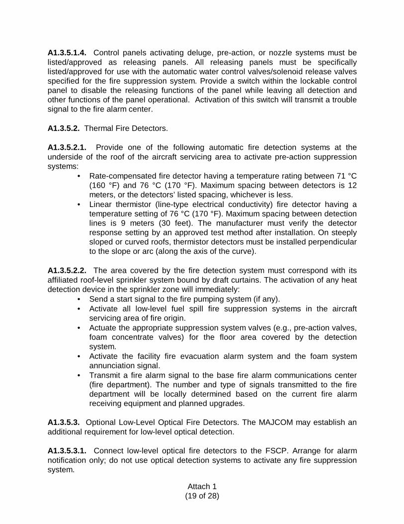
A1.3.5.5.2. Manual foam discharge stations must be yellow and distinctively differentfrom the manual fire alarm stations, and will have distinctive signage at each devicestating “START FOAM SYSTEM” in red lettering not less than 76 millimeters (3 inches)high on a yellow or lime-yellow background. The manual foam discharge station mustbe mounted directly on the sign.
Red Letters
Manual foam discharge station
Distinctive yellow sign
Tamper cover
Figure A1.5. Manual Foam Discharge Station, Tamper Cover, and Signage
A1.3.5.5.3. Manual foam discharge stations must be housed within a clear plastictamper cover that must be lifted prior to actuating the station. Any colored portions ofthe tamper covers must be yellow and any lettering on the cover must be “FOAM”; thewords “fire” or “fire alarm” will not appear on the cover.
A1.3.5.5.4. Actuation of any manual foam discharge stations will cause the FSCP to:• Activate foam discharge through the low level high-expansion generators.
STARTFOAM
SYSTEM

Attach 1(22 of 28)
• Activate the facility fire evacuation alarm and the foam system annunciationsignal.
• Transmit a fire alarm signal to the fire department. The number and type ofsignals transmitted to the fire department will be locally determined basedon the current fire alarm receiving equipment.
A1.3.5.6. Foam System Signals. Provide blue visual alarm signals (strobes or rotatingbeacons) within the aircraft servicing area to indicate foam system activation. When thebase has adopted a standard audio-visual signal for foam system activation, the signalsin the facility will comply fully with that base standard.
A1.4. Fire Protection System Water Supply.
A1.4.1. Requirement. Use the base domestic water system for hangar fire protectionsystems whenever adequate capacity (flow rate, pressure, and storage capacity) isavailable. The A-E is responsible for testing and determining the capability of theexisting distribution systems and integrating those systems with the new systems beingdesigned. New hangar fire protection systems will not be connected to exiting non-potable fire protection water supply systems simply because they already exist;connection to existing non-potable systems will be permitted only where the basedomestic water system is inadequate.
A1.4.1.1. Provide booster fire pumps in accordance with paragraph A1.4.3 when thewater flow rate and storage capacity is adequate but pressure is inadequate to meetsystem pressure demands.
A1.4.1.2. Provide a separate dedicated fire protection system water supply when theavailable domestic flow rate is not sufficient to meet the system flow rate demands.When improvements in the existing water distribution system will correct the flow ratedeficiency, a cost analysis will be conducted to determine the least expensive optionbetween constructing a separate dedicated fire protection system water supply andimproving the existing domestic distribution system.
A1.4.2. Fire Protection Water Storage System.
A1.4.2.1. Provide water storage tanks in accordance with NFPA 24. Provide corrosionprotection when steel water tanks and associated piping are used.
A1.4.2.2. Use a single water storage system, when practical, for multiple aircraftfacilities. Limit water supply distribution mains from a fire pump station to less than 450meters (1500 feet). As an exception, the MAJCOM FPE may approve a greater lengthwhen justified by specific physical situations. Such longer systems are subject tohydraulic surge (water hammer). Surge suppression must be provided at each endpoint of the system and at the pump station.
Attach 1(23 of 28)
A1.4.2.3. Provide storage capacity equal to 120 percent of the maximum demand for30 minutes. Divide the required storage capacity between two equal-sized water tanks,each storing one-half of the required volume. The piping configuration must allow waterto be supplied by both reservoirs, and either of the reservoirs if the other is out ofservice.
A1.4.2.4. Provide each tank with a low-water-level alarm and a low-temperature alarm,each transmitting back to the fire department as separate supervisory signals. In areaswith a 90% dry bulb temperature less than 0 °C (32 °F), provide appropriate freezeprotection.
A1.4.2.5. Provide an external visual water-level gauge on each tank.
A1.4.2.6. Provide automatic refill from the base water distribution system.
A1.4.3. Fire Protection Water and Foam Pump Systems.
A1.4.3.1 Design and install pumping installations in accordance with NFPA 20,Standard for the Installation of Stationary Fire Pumps for Fire Protection. Use a singlewater pumping station for multiple aircraft facilities, when practical.
A1.4.3.2. Provide one redundant pump for every water and foam pump system.
A1.4.3.3. Pumps must have electric motor drivers conforming to NFPA 20, supplied bya single reliable power source. Use dual power sources when a single reliable powersource is not available. Use diesel engine drivers only when the installation electricalservice fails to meet the reliable standard and dual power sources are not available.(For pump systems with one primary and one redundant pump, provide one electric andone diesel if the electrical service fails to meet the reliability standard and dual powersources are not available.) The A-E is responsible for determining and documentingthe reliability of the existing power sources. A power source is considered reliable whenthe following are not exceeded:
• Forced downtime, excluding scheduled repairs, 8 consecutive hours for anyone incident over the previous 3 years;
• 24 cumulative hours of downtime during the previous year.
A1.4.3.4. Use “soft start” or variable frequency pump controllers when electric-drivenpumps are installed.
A1.4.3.5. Limit the maximum rated pump size to 9.463 m3pm (9463 lpm) (2500 gpm) at862 kPa (8.5 bar) (125 psi).
A1.4.3.6. Ensure the pumping system will have capacity to meet the maximum demandwhen the largest capacity pump is out of service.

Attach 1(24 of 28)
A1.4.3.7. Provide pressure maintenance pumps (“jockey pumps”) to maintain normaloperating pressure on the system and to compensate for normal system leakage. SeeNFPA 20 for jockey pump flow requirements. The jockey pump's rated pressure mustbe sufficient for the startup and shutdown pressures specified in NFPA 20. Set jockeypump controllers to automatically start and stop in accordance with NFPA 20,paragraph A-11-2.6. Provide run timers to ensure that the jockey pump will operate forat least the minimum time recommended by the manufacturer of the jockey pump’smotor.
A1.4.3.8. Arrange multiple-pump installations for sequential starting at 10-secondintervals until the operating pumps maintain the required pressure. The startingsequence will begin automatically as follows:
• Pump start signal transmitted from the foam system control panel in theprotected facility.
• Drop in system water pressure in accordance with NFPA 20.
A1.4.3.9. Provide connection through the installation fire reporting system to notify thefire department of pump running signals, pump system trouble, tamper and supervisorysignals provided by the pump controllers. Pump running signals will be transmitted as a“fire” signal.
A1.4.3.10. Provide surge arresters to moderate the potentially destructive effects ofpressure surges or water hammer due to pump starting and stopping and valve openingand closing. These hydropneumatic devices absorb pressure surges into aprecalculated volume of captive gas and return the absorbed water volume to thesystem in a controlled fashion. Surge arresters are installed on the system side of thefire pump discharge check valve and as close to the valve as possible. At least onearrester will be provided for each pump and each must be listed/approved as a surgearrester for fire protection piping, with a volume of not less than 378.4 liters (100gallons) and a rated working pressure not less than 1724 kPa (250 psi). Provide eacharrester with an indicating valve to isolate it from the system. Supervision is notrequired. Because of the complex effects of system variables on satisfactoryperformance, the manufacturer should engineer each surge arrester installation.
A1.5. Facility Fire Detection and Alarm System. Design all facility fire detection andalarm systems in accordance with NFPA 72 and the following criteria.
A1.5.1. Fire Alarm Control Panel (FACP).
A1.5.1.1. Locate all FACPs in a clean environment with temperature and humiditycontrol in accordance with the unit’s listing/approval.
A1.5.1.2. FACPs will have TVSS on all fire alarm circuits entering and leaving thefacility, including, but not limited to, the power supply circuits to the FACP, circuitsinterfacing with fire pumping stations outside the facility, and circuits interfacing with

Attach 1(25 of 28)
the fire alarm receiving station (e.g., communication circuits, antenna systems). TVSSdevices must comply with the requirements of paragraph A1.3.5.1.2.
A1.5.1.3. Provide a single FACP for all detection alarm functions in the facility that arenot part of the foam-water fire suppression system. The FACP must be fully compatiblewith the base fire alarm receiving system without field modifications to any systemhardware or software.
A1.5.1.4. Separate fire alarm transmitters/receivers are permitted when they are fullycompatible with the FACP and the base fire alarm receiving system without fieldmodifications to the FACP.
A1.5.1.5. The specific number of alarm signals to be transmitted will be defined in thesystem matrix (Figure A1.6).
A1.5.2. Manual Fire Alarm Stations (Pull Stations).
A1.5.2.1. Provide pull stations throughout the facility at all exit doors. Provideadditional pull stations when required by NFPA 101.
A1.5.2.2. Ensure all manual alarm activation stations are identical throughout thefacility. If the base has established a formal base-wide standard for manual pullstations, the pull stations in facilities governed by this ETL will comply fully with thatstandard.
A1.5.2.3. Actuation of any manual alarm activation stations will immediately cause theFACP to:
• Activate the facility fire evacuation alarm signal throughout the facility.• Transmit a fire alarm signal to the base fire department.
A1.5.3. Fire Alarm Notification. Provide audio-visual alarm notification devices. Whenthe base has a standard for audible sound (e.g., slow whoop, bell) and visual signal(red, white), the devices in the facility will comply fully with the base standards. Noother system (hangar doors, alert signal) will be permitted to use these signals. The firealarm must be distinctive in high-noise areas.
A1.5.4. Temperature Monitoring System.
A1.5.4.1. Provide a system of temperature sensors for the aircraft servicing area in allgeographic areas having a 99.6% dry bulb temperature less than -1 °C (30 °F) whenwet-pipe sprinkler systems are present. The temperature sensors will be located at thesame level as the sprinkler piping and spaced not more than 60 meters (200 feet)apart. Provide this temperature monitoring to ensure a warning when freezingtemperatures endanger sprinkler piping.

Attach 1(26 of 28)
A1.5.4.2. This facility temperature monitoring system will be tied into the FACP as adedicated supervisory zone, and this supervisory signal will be transmitted to the firedepartment in the same manner as all fire-related supervisory signals in the facility.

Fig
ure
A1.
6.S
amp
leF
acili
tyF
ire
Det
ecti
on
and
Ala
rmS
yste
mF
un
ctio
nal
Mat
rix
AN
NU
NC
IAT
ION
AT
LOC
AL
PA
NE
LSF
IRE
SU
PP
RE
SS
ION
SY
ST
EM
FU
NC
TIO
NS
TR
AN
SM
ITS
IGN
ALS
TO
FIR
ED
EP
AR
TM
EN
TA
UX
ILIA
RY
FU
NC
TIO
NS
EV
AC
UA
TIO
NS
IGN
ALS
SY
ST
EM
INP
UT
S
Audio-VisualFireAlarmIndicationbyZone
Audio-VisualTroubleIndicationbyZone/Middle
Audio-VisualCommonTroubleIndication
Audio-VisualAlarmIndicationbyDevice
TransmitPumpStartSignaltoPumphouse
OpenPre-ActionSprinklerValves
OpenAllLow-LevelHigh-Expansion
DivertDrainFlowfromSeparatorstoContainmentCommonTroubleSignalPerBuilding
CommonSupervisorySignalPerBuilding
CommonFireAlarmPerGeneralArea
SprinklerWaterFlowPerGeneralArea
Low-LevelOpticalDetectorsPerGeneralArea
Foam-WaterDischargePerGeneralArea
ShutDownAllSupply&RecirculatingFans
ReleasemagneticallyHeldSmokeDoors
FacilityFireEvacuationAudio-VisualSignal
FoamSystemSignalBlueStrobe/Beacon
FIR
EA
LAR
MS
AB
CD
EF
GH
IJ
KL
MN
OP
QR
1M
anua
lFire
Ala
rmS
tatio
nsx
xx
x2
Spo
t-T
ype
Sm
oke
Det
ecto
rsx
xx
xx
3F
ixed
Tem
p&
Rat
e-of
-Ris
eT
ype
Hea
tDet
ecto
rsx
xx
x4
In-D
uctS
mok
eD
etec
tors
xx
xx
x5
Rat
e-C
ompe
nsat
edT
ype
Hea
tDet
ecto
rson
Han
gar
Cei
ling
x6
Wat
erF
low
Sw
itche
s-
Wet
orD
ry-P
ipe
Spr
inkl
erS
yste
ms
inA
djac
entA
reas
xx
xx
x
7W
ater
Flo
wS
witc
hes
-P
re-A
ctio
nS
prin
kler
Sys
tem
sx
8W
ater
Sw
itche
s-
Low
-leve
lHig
h-ex
pans
ion
Sys
tem
x9
Man
ualF
oam
Dis
char
geS
tatio
nfo
rLow
-Lev
elx
10Lo
wLe
velO
ptic
alF
ireD
etec
tor
xS
UP
ER
VIS
OR
YS
IGN
ALS
11V
alve
Sup
ervi
sory
Sw
itch
-W
etor
Dry
-Pip
eS
prin
kler
sin
Adj
acen
tAre
asx
x12
Val
veS
uper
viso
ryS
witc
hes
-Spr
inkl
ers
13V
alve
Sup
ervi
sory
Sw
itche
s-L
ow-L
evel
Hig
h-E
xpan
sion
Sys
tem
14V
alve
Sup
ervi
sory
Sw
itche
s-W
ater
Sup
ply
Ent
ranc
e15
Hi-L
oP
ress
ure
Sw
itche
s-
Dry
-Pip
eS
prin
kler
sx
x16
Tem
pera
ture
Mon
itorin
gS
yste
mx
x17
Low
-Lev
elO
ptic
alF
ireD
etec
tor
Tro
uble
18C
ontr
olC
ompo
nent
Com
mon
Tro
uble
Con
ditio
nx
x19
Und
er-A
ircra
ftF
oam
-Wat
erS
yste
mA
uto
Dis
able
Sw
itch
TR
OU
BLE
CO
ND
ITIO
NS
20Lo
wB
atte
ryV
olta
gex
x21
Circ
uitF
ault
xx
x22
Sup
ervi
sed
Com
pone
ntF
ailu
rex
x23
AC
Pow
erF
ailu
rex
xN
OT
ES
:1.
Fire
alar
msi
gnal
san
dsu
perv
isor
yal
arm
sign
als
shal
lbe
clea
rlydi
ffere
ntia
ted
atth
efir
eal
arm
cont
rolp
anel
(s).
2G
ener
alar
eam
eans
the
spec
ific
bay,
dock
,mez
zani
ne,o
ffice
area
,or
mec
hani
cala
rea.
Sys
tem
zoni
ngsh
allb
esu
ffici
entt
odi
rect
resp
ondi
ngfir
efig
hter
sdi
rect
lyto
the
fire
area
.3,
Thi
ssa
mpl
em
atrix
show
sth
eba
sic
requ
irem
ents
and
isex
pect
edto
beta
ilore
dto
each
indi
vidu
alpr
ojec
t.
Atch 1(26 of 28)
Atch 1(27 of 28)
A1.6. Design and Construction Management.
A1.6.1. A-E Qualifications.
A1.6.1.1. It is mandatory that design organizations (whether the design isaccomplished by an in-house design agent or an outside A-E firm) use a qualified FPE,experienced in the design of aircraft hangars, for the design of the fire protectionsystems in all Air Force projects covered by this ETL.
A1.6.1.1.1. “Qualified FPE” does not have a universal definition and is defineddifferently among various government agencies. For this ETL, one of the followingcredentials is required to meet the criteria for “qualified FPE”:
• Bachelor of Science or Master of Science degree in fire protectionengineering from an accredited university, plus a minimum of 5 years’ workexperience in fire protection engineering.
• Professional Engineer (PE) registration by examination, National Council ofExaminers for Engineering and Surveys (NCEE) fire protection engineeringwritten examination.
• Qualification as a GS/GM 804-series FPE.• PE registration in a related discipline with a minimum of 5 years’ work
experience in fire protection engineering.
A1.6.1.1.2. For Air Force aircraft hangars, the design agent will confirm that:• Designer complies with the definition of “qualified FPE.”• FPE has substantial experience in the design and construction of aircraft
hangar fire protection systems of similar complexity.
A1.6.1.2. The Commerce Business Daily announcement for the project design willspecifically include the requirement for a qualified FPE on the A-E design team.
A1.6.2. System Testing and Acceptance:
A1.6.2.1. Preliminary Testing.
A1.6.2.1.1. Testing of the fire protection system is critical. The entire fire protectionsystem must be tested in accordance with the specification to ensure that allequipment, components, and subsystems function as intended. In addition toestablishing written confirmation of all test results, all preliminary tests will bevideotaped to record the methods and equipment employed to conduct the tests.
A1.6.2.1.2. A copy of the videotape must be submitted with a copy of the proposed testplan to the USACE Center of Expertise or NAVFACENGCOM FPE before the requestfor a final acceptance test is made. All preliminary tests must be completed prior toscheduling the final acceptance test.
Atch 1(28 of 28)
A1.6.2.2. Final Acceptance Test. The final test will be a repeat of all preliminary tests,except that flushing and hydrostatic tests will not be repeated. Tests must be witnessedby the USACE Center of Expertise or NAVFACENGCOM FPE. All system failures orother deficiencies identified during the testing must be corrected and retested in thepresence of the USACE Center of Expertise or NAVFACENGCOM FPE.
Atch 2(1 of 3)
LOW-LEVEL HIGH-EXPANSION FOAM SYSTEM VIEWS
Figure A2.1. Low-Level High-Expansion Foam Wall-Mounted (Adjacent LeadingWing Edge) Generators’ Initial Discharge
Figure A2.2. Low-Level High-Expansion Foam After Three-Minute Discharge
Atch 2(2 of 3)
Figure A2.3. Low-Level High-Expansion Ceiling-Mounted Generators’ FoamDischarge
Figure A2.4. Low-Level High-Expansion Foam After 15-Minute Discharge

Atch 2(3 of 3)
Figure A2.5. Low-Level High-Expansion Foam After 7-Minute Discharge

Atch 3(1 of 1)
DISTRIBUTION LIST
DEPARTMENT OF DEFENSE
Defense Commissary Service (1)Director of FacilitiesBldg 8400Lackland AFB TX 78236-5000
AAFES/ATTN: CFE (1)PO Box 660320Dallas TX 75266-0320
Defense Technical InformationCenter (1)
ATTN: DTIC-FDAAlexandria VA 22034-6145
SPECIAL INTEREST ORGANIZATIONS
IHS (A.A. DeSimone) (1)1990 M Street NW, Suite 400Washington DC 20036
Construction Criteria Database (1)National Institute of Bldg Sciences1201 L Street NW, Suite 400Washington DC 20005