Embed Size (px)
Citation preview

DEPARTMENT OF THE AIR FORCE HEADQUARTERS AIR FORCE CIVIL ENGINEER SUPPORT AGENCY
1 MAR 2010
APPROVED FOR PUBLIC RELEASE: DISTRIBUTION UNLIMITED
FROM: AFCESA/CEO 139 Barnes Drive, Suite 1 Tyndall AFB FL 32403-5319 SUBJECT: Engineering Technical Letter (ETL) 10-3: Procedures and Acceptance
Criteria for Protective Materials Resistant to 155 mm and Smaller Fragmenting Munitions
1. Purpose. This ETL describes procedures and acceptance criteria for testing and approval of typical building construction materials or composite sections for resistance to fragments and air blast from 155 mm and smaller fragmenting munitions. Note: The use of the name or mark of any specific manufacturer, commercial product, commodity, or service in this publication does not imply endorsement by the Air Force. 2. Application.
2.1. Authority: Air Force policy directive (AFPD) 32-10, Installations and Facilities
2.2. Effective Date: Immediately 2.3. Intended Users: Manufacturers and designers of force protection facilities and facility components 2.4. Coordination:
• Air Force Research Lab (AFRL) • Army Engineer Research and Development Center (ERDC) • Army Protective Design Center (PDC) • Naval Facilities Engineering Command (NAVFAC)
3. References.
3.1. Air Force: • (AFPD) 32-10, Installations and Facilities, http://www.e-publishing.af.mil/
3.2. Army:
• International Test Operations Procedures (ITOP) 2-2-722, Fragment Penetration Tests of Armor, 20 Nov 2002, https://itops.dtc.army.mil/II_Weapons.aspx
2
3.3. Joint: • North American Treaty Organization Standardization Agreement (NATO
STANAG) 2920, Ballistic Test Method for Personal Armour Materials and Combat Clothing, 2003, http://nsa.nato.int/nsa/
3.4. Federal:
• MIL-DTL-46593B, Projectile, Calibers .22, .30, .50, and 20mm Fragment-Simulating, 11 Aug 2008
3.5. ASTM International (http://www.astm.org):
• ASTM A29/A29M, Standard Specification for Steel Bars, Carbon and Alloy, Hot-Wrought, General Requirements for
• ASTM A108, Standard Specification for Steel Bars, Carbon and Alloy, Cold-Finished
• ASTM B209, Standard Specification for Aluminum and Aluminum-Alloy Sheet and Plate
4. Acronyms. BL - ballistic limit C - Celsius C-4 - Composition 4 cm - centimeter CMU - concrete masonry unit CP - complete penetration F - Fahrenheit fps - foot per second FSP - fragment-simulating projectiles ft - foot ft/s - foot per second g - gram in. - inch m - meter m/s - meter per second mm - millimeter mps - meter per second MSDS - Material Safety Data Sheet PP - partial penetration psi - pound per square inch psi-msec - pound per square inch – millisecond TNT - trinitrotoluene 5. Definitions.
5.1. Ballistic Impact. Impacts due to hits on the target by projectiles, fragments, or fragment simulating projectiles
3
5.2. Complete Penetration (CP). A CP occurs when a piece of either the impacting fragment or the building material has sufficient energy to damage a 0.51-millimeter (mm) (0.02-inch [in.]) 2024 T3 aluminum (ASTM B209, Standard Specification for Aluminum and Aluminum-Alloy Sheet and Plate) (or equivalent) witness panel. Damage in this case is defined as the ability to see light through the witness panel. The witness panel is mounted parallel to and 152 mm ± 12.7 mm (6 in. ± 0.5 in.) behind the rear of the target. 5.3. Partial Penetration (PP). A PP occurs when a fair hit or significant hit causes less than a CP in laboratory testing or arena testing respectively. 5.4. Percent Penetration. One hundred (100) times the ratio of CPs to significant hits as a result of fragments from a fragmenting warhead interacting with a target. 5.5. Percent Protection Level. One (1) minus the percent penetration. 5.6. Significant Hit Panel. A 0.51-mm (0.02-in.) -thick 2024 T3 aluminum sheet (or equivalent) panel is placed 152 mm ± 12.7 mm (6 in. ± 0.5 in.) in front of and parallel to the target to determine if a hit is significant. Any fragment capable of perforating this panel is considered a significant hit. 5.7. Witness Panel. A 0.51-mm (0.02-in.) -thick 2024 T3 aluminum sheet (or equivalent) panel is placed 152 mm ± 12.7 mm (6 in. ± 0.5 in.) behind and parallel to the target to witness CPs of fragments or spall material.
6. Specific Requirements. This paragraph describes the necessary test conditions, data requirements, and data analysis procedures for conducting static detonation tests against typical building materials using fragmenting munitions such as mortars or rockets.
6.1. Scope. Compliance with this ETL will require successful completion of a static detonation evaluation. A static detonation evaluation will consist of a minimum of three tests.
6.1.1. Surrogate warheads may be used if produced in accordance with approved drawings (see Attachment 1). 6.1.2. To reduce overall development costs, it is recommended that vendors conduct V0 ballistic limit testing of their products prior to conducting static detonation testing. Attachment 2 discusses V0 ballistic limit testing.
6.2. Static detonation testing must be conducted at an independent explosives test laboratory where the proper equipment is present and approved for use. In addition, the facility must have adequate space to safely conduct fragmenting warhead tests. Table 1 lists equipment and basic material required to conduct this type of testing.
4
Table 1. Required Equipment and Material
Item Requirement Target structure A minimum 2.4 m x 2.4 m (8 ft x 8 ft) section of
selected building material that represents a typical example of construction. Multiple targets are required for a typical test series.
Target mount Holds the target in a fixed position at the required obliquity to the surrogate warhead. Also provides support to the target structure similar to what would be seen in actual construction.
Actual or surrogate warhead Produces fragmentation and blast loading. Warhead fixture Holds warhead in the nose down configuration. Witness panel and significant hit panel material
Two pieces of 0.51 mm (0.02 in.) 2024 T3 aluminum alloy (or equivalent) to determine significant hits and penetration classification. Mounted 152 mm ± 12.7 mm (6 in. ± 0.5 in.) in front of and behind target structure.
High-speed digital camera Images of test impact for detailed analysis. Must be capable of 20,000 frames per second with minimum 256 x 256 pixel resolution. Black-and-white cameras produce higher quality results than color cameras due to their higher resolution and reduced light requirements.
Pressure gauges Record incidental blast pressure at uniform distance away from the surrogate warhead.
Gauge shield pole Shields pressure gauges from fragments generated by the surrogate warhead.
Still photographic equipment Documents test setup and results.
6.2.2. The static detonation test subjects the target to actual fragments and some of the random factors that influence penetration. These factors include fragment shape, impact orientation, and weight. Therefore, it is necessary to conduct multiple tests when evaluating targets against static detonations. At least three tests are required to meet compliance with this ETL and five tests are preferred. When multiple target types need to be tested, it is best to include multiple target types during each shot. This has an advantage because each target type is subjected to the same threat characteristics, thus reducing some of the round-to-round variations. 6.2.3. For this ETL, the distance between the warhead and the test wall will be 3 m (10 ft).
5
6.2.4. During the detonation process, explosively generated fragments travel at approximately an 8° angle from perpendicular, a phenomenon known as beam angle or beam spray. The warhead shall be placed nose-down on the ground for testing. When the warhead is detonated nose-down (with detonator in the nose) the beam spray will be 8° up from perpendicular. For example, in the case of the 122 mm rocket, if the nose is positioned on the ground the fragments will be concentrated at approximately 74 centimeters (cm) (29 in.) above the ground at a range of 3 m (10 ft) (see Figure 1).
Figure 1. 122 mm Surrogate Beam Angle (Nose Initiation, Nose Down)
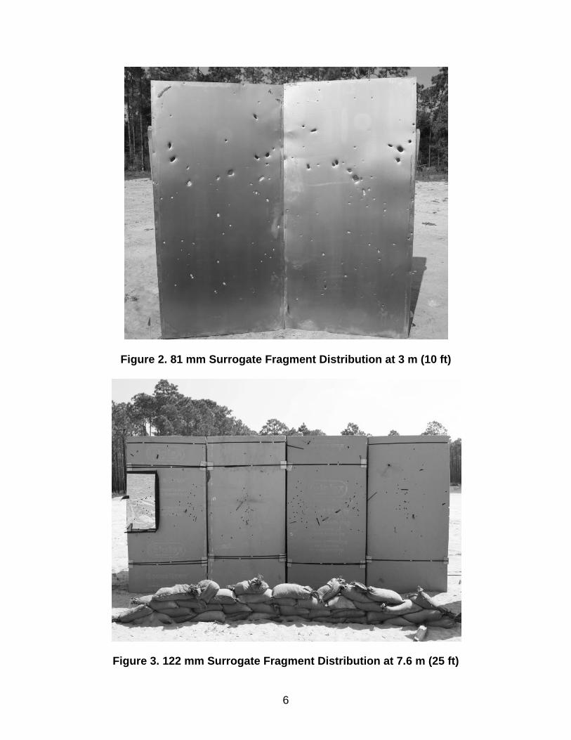
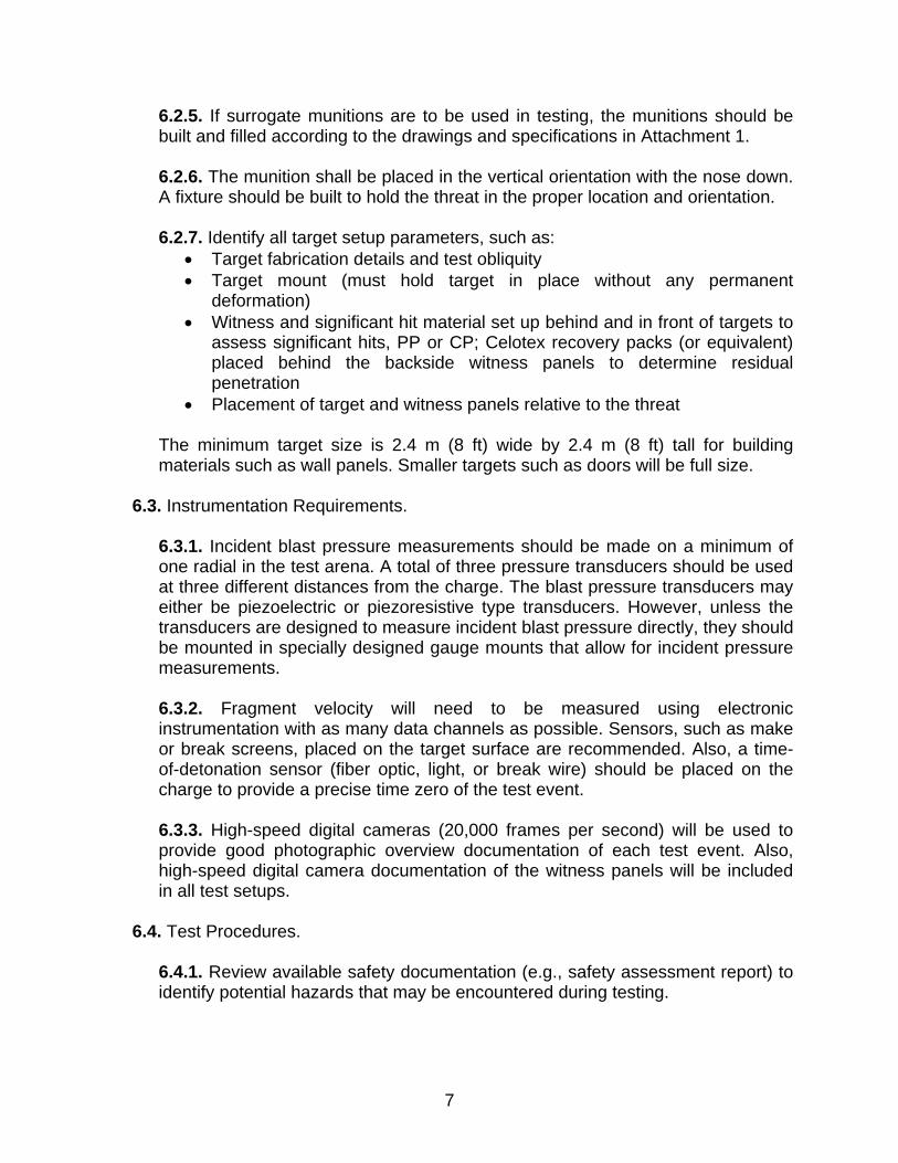
6.2.4. Each type of warhead generates different fragment patterns based on the warhead design. For example, the 81 mm mortar surrogate is a naturally fragmenting warhead, has a rather poor fragment density, and scatters quickly at a range of 3 m (10 ft) (see Figure 2). On the other hand, the 122 mm surrogate rocket has a naturally fragmenting outer case and two scored inner liners which produce a high fragment density focused along the beam angle, even at a range of 7.6 m (25 ft) (see Figure 3). The horizontal grouping on the 122 mm example is due to the pre-scoring of the warhead liners, and represents the impact of one “row” of fragments (see surrogate warhead drawings in Attachment 1).
6
Figure 2. 81 mm Surrogate Fragment Distribution at 3 m (10 ft)
Figure 3. 122 mm Surrogate Fragment Distribution at 7.6 m (25 ft)
7
6.2.5. If surrogate munitions are to be used in testing, the munitions should be built and filled according to the drawings and specifications in Attachment 1. 6.2.6. The munition shall be placed in the vertical orientation with the nose down. A fixture should be built to hold the threat in the proper location and orientation. 6.2.7. Identify all target setup parameters, such as:
• Target fabrication details and test obliquity • Target mount (must hold target in place without any permanent
deformation) • Witness and significant hit material set up behind and in front of targets to
assess significant hits, PP or CP; Celotex recovery packs (or equivalent) placed behind the backside witness panels to determine residual penetration
• Placement of target and witness panels relative to the threat
The minimum target size is 2.4 m (8 ft) wide by 2.4 m (8 ft) tall for building materials such as wall panels. Smaller targets such as doors will be full size.
6.3. Instrumentation Requirements.
6.3.1. Incident blast pressure measurements should be made on a minimum of one radial in the test arena. A total of three pressure transducers should be used at three different distances from the charge. The blast pressure transducers may either be piezoelectric or piezoresistive type transducers. However, unless the transducers are designed to measure incident blast pressure directly, they should be mounted in specially designed gauge mounts that allow for incident pressure measurements. 6.3.2. Fragment velocity will need to be measured using electronic instrumentation with as many data channels as possible. Sensors, such as make or break screens, placed on the target surface are recommended. Also, a time-of-detonation sensor (fiber optic, light, or break wire) should be placed on the charge to provide a precise time zero of the test event. 6.3.3. High-speed digital cameras (20,000 frames per second) will be used to provide good photographic overview documentation of each test event. Also, high-speed digital camera documentation of the witness panels will be included in all test setups.
6.4. Test Procedures.
6.4.1. Review available safety documentation (e.g., safety assessment report) to identify potential hazards that may be encountered during testing.
8
6.4.2. Review available environmental documentation (e.g., Material Safety Data Sheets [MSDS] listing contents of threats and targets) to determine appropriate handling and disposal procedures for explosive residue and target components. 6.4.3. Review necessary security documentation to ensure appropriate protection of threat, target, and data. 6.4.4. Identify all instrumentation requirements. These may include instrumentation to measure fragment striking velocity, depth of penetration, and residual fragment velocity and mass. Consideration should be given to protecting instrumentation from fragments, blast, and other hazards. Armored troughs, sand bags, steel shielding, etc., may be used for protection.
6.5. Arena Setup.
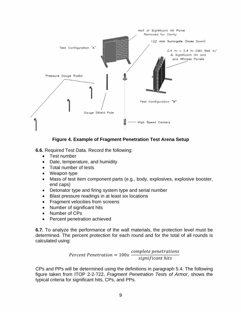
6.5.1. Position the threat in the center of the test arena. The threat should be positioned using a wooden stand constructed to hold the threat in a nose-down orientation. 6.5.2. Position the targets at a specified 3-m (10-ft) distance from the given high-explosive (HE) threat. Configuration of the test setup is dependent on the size and number of targets. 6.5.3. Position the pressure gauge radials so that they are 180° apart in the arena and 90° from the target. One of the gauge distances used will be the same as the target distance. 6.5.4. A conceptual example of a test setup is shown in Figure 4.
9
Figure 4. Example of Fragment Penetration Test Arena Setup
6.6. Required Test Data. Record the following: • Test number • Date, temperature, and humidity • Total number of tests • Weapon type • Mass of test item component parts (e.g., body, explosives, explosive booster,
end caps) • Detonator type and firing system type and serial number • Blast pressure readings in at least six locations • Fragment velocities from screens • Number of significant hits • Number of CPs • Percent penetration achieved
6.7. To analyze the performance of the wall materials, the protection level must be determined. The percent protection for each round and for the total of all rounds is calculated using:
100
CPs and PPs will be determined using the definitions in paragraph 5.4. The following figure taken from ITOP 2-2-722, Fragment Penetration Tests of Armor, shows the typical criteria for significant hits, CPs, and PPs.
10
Figure 5. Typical Criteria for Significant Hits and Complete and Partial Penetrations
6.7.1. Calculate fragment velocity data based upon the time from detonation to fragment impact on the target. This time divided by the distance from the threat to the target provides an average fragment velocity over that distance. 6.7.2. Produce blast pressure traces to include the peak incident pressure reading and peak incident impulse. This data should be compared to the graphs in Attachment 3 to ensure complete detonation of the explosive fill of the threat. The graphs were generated in ConWep (Army conventional weapons effects calculations software) using a case correction from the Protective Construction Design Manual and match data generated by the actual ordnance and properly prepared surrogates.
6.8. The acceptance criteria are a percent penetration of 2% for a minimum of three tests. Test data requirements of paragraph 6.6 must be submitted to the point of contact in paragraph 7 for approval.
11
7. Point of Contact. Recommendations for improvements to this ETL are encouraged and should be furnished to: HQ AFCESA/CEOA, 139 Barnes Drive, Suite 1, Tyndall AFB, FL 32408-5319, Attention: Force Protection Subject Matter Expert, DSN 523-6119, commercial (850) 283-6119, email [email protected]. LESLIE C. MARTIN, Colonel, USAF 4 Atchs Chief, Operations and Programs Support Division 1. Surrogate Warhead
Fabrication 2. V0 Ballistic Limit Testing 3. Pressure Data 2. Distribution List
Atch 1
(1 of 16)
SURROGATE WARHEAD FABRICATION A1.1. The 81 mm surrogate is fabricated from a single piece of 1018 or 1020 mild steel round stock in accordance with the included drawing set. The surrogate is filled with cast TNT and uses C-4 as a booster in the fuze well. Figure A1.1 shows 81 mm surrogate bodies as completed by a machine shop.
Figure A1.1. 81 mm Surrogates prior to Explosive Fill A1.2. Prior to adding the explosive fill, it is important to clean the 81 mm surrogates of any oils or cutting fluids to avoid any unsafe reaction with the fill mixture. A1.3. Vendors with 81 mm surrogate manufacturing experience: B&B Machine and Grinding Service Corporation 303 West Evans Avenue Denver, CO 80223 Phone: (303) 744-2751 Fax: (303) 744-2802 http://www.bandbmachineshop.com/ Accudyne Corporation 2835 South Raritan Street Englewood, CO 80110 Phone: (303) 991-1500 Fax: (303) 991-1921 http://www.eztram.com/
Atch 1
(2 of 16)
A1.4. The 122 mm surrogate is fabricated from three separate components in accordance with the included drawing set: (1) the main body; (2) the outer fragmentation liner; and (3) the inner fragmentation liner. The main body is machined from 1018 or 1020 mild steel round stock. The machine shop selected to produce the main body must have a lathe capable of handling the long boring bar necessary for fabrication. The inner and outer liners are fabricated from 1025 or 1026 mild steel tube stock. Figure A1.2 shows the main body and inner and outer liners as received from the machine shop and prepped for assembly. Prior to assembly, it is important to clean the 122 mm surrogate components of any oils or cutting fluids to avoid any unsafe reaction with the explosive fill mixture and excessive smoking during the assembly process. The 122 mm surrogate is filled with cast TNT in the nose section and AFX-795 or equivalent explosive in the fragmentation liner section. C-4 is used as a booster in the fuze well.
Figure A1.2. 122 mm Surrogate Components Prior to Assembly
A1.5. To achieve the interference fit between the three components, a simple thermal process is used for assembly.
Atch 1
(3 of 16)
Stage #1: Insert Inner Fragmentation Liner into Outer Fragmentation Liner
• Chill inner liner in a standard household or commercial freezer/deep freezer for approximately two hours to ensure uniform desired temperature.
• Heat outer liner in a standard household or commercial oven to 500 °F (260 °C) for one hour to ensure uniform desired temperature.
• Using gloves, remove outer liner from oven and place upright on a hard, heat-resistant surface. Remove inner liner from freezer. Immediately drop inner liner into outer liner. Any delay in the installation process can cause the two components to seize in the wrong position as they equalize in temperature. A mallet may be employed to help components fit together. Figure A1.3 shows the completed liner assembly.
• Allow liner assembly to return to room temperature.
Figure A1.3. Outer Liner with Inner Liner Installed Stage #2: Insert Fragmentation Liner Assembly into Main Body
• Heat main body in standard household or commercial oven to 500 °F (260 °C) for one hour to ensure uniform desired temperature. Ensure oven is large enough to accommodate the length of the main body.
• Chill liner assembly in bath of dry ice and acetone for 30 minutes to ensure uniform desired temperature. Figure A1.4 shows an example of this process.
Atch 1
(4 of 16)
Figure A1.4. Fragmentation Liner Assembly in Dry Ice and Acetone Bath
• Using gloves, remove main body from oven and place upright on a hard, heat-resistant surface. Ensure main body is stable. Remove liner assembly from bath. Immediately drop liner assembly into main body. Any delay in the installation process can cause the two components to seize in the wrong position as they equalize in temperature. A mallet may be employed to help components fit together. Figure A1.5 show this installation process. Figure A1.6 shows the liner assembly correctly installed in the main body.
• Allow the completed surrogate to return to room temperature. Figure A1.7 shows the completed surrogate ready for explosive fill.
Atch 1
(5 of 16)
Figure A1.5. Fragmentation Liner Assembly and Main Body Installation Process
Figure A1.6. Fragmentation Liner Assembly installed in the Main Body
Atch 1
(6 of 16)
Figure A1.7. 122 mm Surrogate prior to Explosive Fill A1.6. Vendors with 122 mm surrogate manufacturing experience: Main Body: Bogue Machine Company 7401 Edith Boulevard NE Albuquerque, NM 87113 Phone: (505) 344-9988 Fax: (505) 344-5510 http://www.boguemachine.com/ Inner and Outer Fragmentation Liners: B&B Machine and Grinding Service 303 West Evans Avenue Denver, CO 80223 Phone: (303) 744-2751 Fax: (303) 744-2802 http://www.bandbmachineshop.com/
Atch 1 (7 of 16)
Figure A1.8. 122 mm Surrogate
Atch 1 (8 of 16)
Figure A1.9. 122 mm Surrogate Explosive Fill Diagram
Atch 1 (9 of 16)
Figure A1.10. 122 mm Surrogate Main Body
Atch 1 (10 of 16)
Figure A1.11. 122 mm Surrogate Outer Liner
Atch 1 (11 of 16)
Figure A1.12. 122 mm Surrogate Inner Liner
Atch 1 (12 of 16)
Figure A1.13. 122 mm Surrogate Liner Scoring Detail
Atch 1 (13 of 16)
Figure A1.14. 81 mm Surrogate Exterior Dimensions
Atch 1 (14 of 16)
Figure A1.15. 81 mm Surrogate Explosive Fill Diagram
Atch 1 (15 of 16)
Figure A1.16. 81 mm Surrogate Interior Dimensions
Atch 1 (16 of 16)
Figure A1.17. 81 mm Surrogate Gas Ring Detail
Atch 2 (1 of 7)
V0 BALLISTIC LIMIT TESTING
A2.1. V0 Ballistic Limit Testing Procedure.
A2.1.1. The problem of defeating fragments from a weapon at a specific standoff distance with a defined percent protection level can be reduced to the problem of defeating a single fragment at some strike velocity. Therefore, it is recommended that selected building materials should first be evaluated against fragment simulators to reduce development costs. If the desired performance is achieved then static detonation tests are required to be in compliance with this ETL.
A2.1.2. Fragment simulator testing has the following positive characteristics:
• Fragments possess consistent weight, shape, and material properties • Fragments can be mass produced and are relatively inexpensive • Relatively precise velocity control is easily achieved, permitting consistent test
conditions • Small targets and modest range facilities are required.
A2.1.3. It is important to note that fragment simulators do not replicate the wide variety of shapes and striking orientation of actual explosively generated fragments. Instead, they provide a good working average that is useful in the screening process.
A2.2. V0 Ballistic Limit (V0 BL). The V0 BL is defined as the highest velocity of a threat at zero degree obliquity at which the probability of complete penetration (CP) is zero percent. A2.3. Definitions.
A2.3.1. Ballistic Impact. Impacts due to hits on the target by projectiles, fragments, or fragment-simulating projectiles (FSP). A2.3.2. Complete Penetration (CP). A CP occurs when a piece of either the impacting fragment or the building material has sufficient energy to damage a 0.51-mm (0.02-in.) 2024 T3 aluminum (or equivalent) witness panel. Damage in this case is defined as the ability to see light through the witness panel. The witness panel is mounted parallel to and 152 ± 12.7 mm (6 in. ± 0.5 in.) behind the rear of the target. A2.3.3. Fair Hit. In ballistic testing, impact shall be considered fair when a fragment simulator or test projectile strikes an unsupported area of the target material at a distance of at least two projectile diameters from any previous impact or disturbed area resulting from an impact, or from any crack, or from any edge of the test specimen.
Atch 2 (2 of 7)
A2.3.4. Fragment-Simulating Projectiles (FSP). A group of projectiles that have been shown to provide a convenient and reasonably accurate set of laboratory simulators for common warhead fragments in defining ballistic performance for protective materials. FSP are manufactured in accordance with MIL-DTL-46593B, Detail Specification – Projectile, Calibers .22, .30, .50, and 20mm Fragment-Simulating. A2.3.5. Partial Penetration (PP). A PP occurs when a fair hit causes less than a CP in laboratory testing or arena testing respectively. A2.3.6. Witness Panel. A 0.51-mm (0.02-in.) -thick 2024 T3 aluminum (or equivalent) sheet is placed 152 mm ± 12.7 mm (6 in. ± 0.5 in.) behind and parallel to the target to witness CPs of fragments or spall material.
A2.4. V0 BL testing uses a research gun to fire simulated fragments into sample building material components. As a general procedure, components should first be tested with gun-launched fragment simulators to provide a good initial assessment of the building material’s resistance to ballistic impact. A2.5. Fragment simulator testing can be conducted at an independent ballistics laboratory where the proper equipment is present and approved for use. Table A2.1 lists equipment and basic materials required to conduct this type of testing (also see Figure A2.1).
Table A2.1. Typical Setup for Fragment Simulator Testing
Item Requirement Target structure A small section of selected building material
components that represent a typical example of construction. Multiple targets are required for a typical test series.
Support frame Holds the target structure in a fixed position at the required obliquity.
Research gun A breech-loading gun, rifled or smoothbore, that can launch FSPs at required velocity levels (usually up to 1,829 mps or 6,000 fps) with high repeatability. Suitable bore size usually varies from 5.56 mm–57 mm. Firing is usually conducted remotely to allow for syncing with cameras and data acquisition systems.
Fragment simulating projectile (FSP) Manufactured in accordance with MIL-DTL-46593B
Atch 2 (3 of 7)
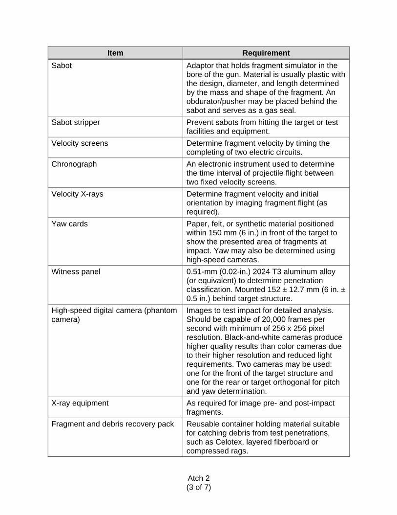
Item Requirement Sabot Adaptor that holds fragment simulator in the
bore of the gun. Material is usually plastic with the design, diameter, and length determined by the mass and shape of the fragment. An obdurator/pusher may be placed behind the sabot and serves as a gas seal.
Sabot stripper Prevent sabots from hitting the target or test facilities and equipment.
Velocity screens Determine fragment velocity by timing the completing of two electric circuits.
Chronograph An electronic instrument used to determine the time interval of projectile flight between two fixed velocity screens.
Velocity X-rays Determine fragment velocity and initial orientation by imaging fragment flight (as required).
Yaw cards Paper, felt, or synthetic material positioned within 150 mm (6 in.) in front of the target to show the presented area of fragments at impact. Yaw may also be determined using high-speed cameras.
Witness panel 0.51-mm (0.02-in.) 2024 T3 aluminum alloy (or equivalent) to determine penetration classification. Mounted 152 ± 12.7 mm (6 in. ± 0.5 in.) behind target structure.
High-speed digital camera (phantom camera)
Images to test impact for detailed analysis. Should be capable of 20,000 frames per second with minimum of 256 x 256 pixel resolution. Black-and-white cameras produce higher quality results than color cameras due to their higher resolution and reduced light requirements. Two cameras may be used: one for the front of the target structure and one for the rear or target orthogonal for pitch and yaw determination.
X-ray equipment As required for image pre- and post-impact fragments.
Fragment and debris recovery pack Reusable container holding material suitable for catching debris from test penetrations, such as Celotex, layered fiberboard or compressed rags.
Atch 2 (4 of 7)
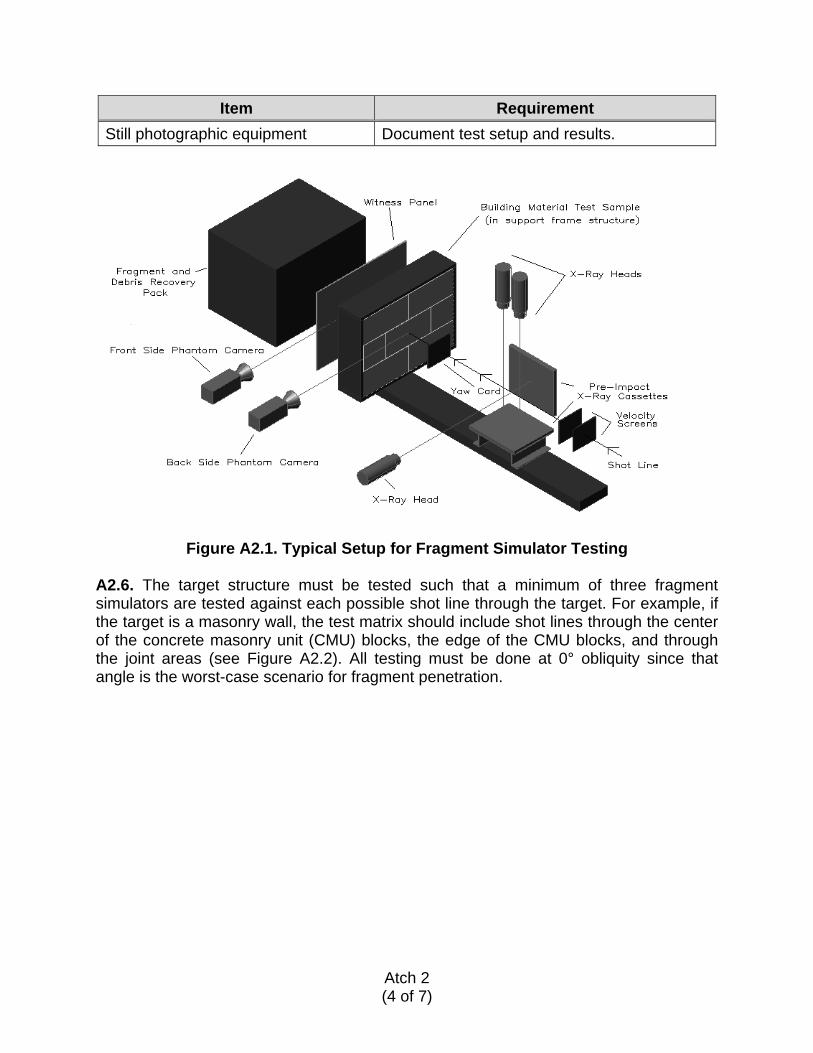
Item Requirement Still photographic equipment Document test setup and results.
Figure A2.1. Typical Setup for Fragment Simulator Testing A2.6. The target structure must be tested such that a minimum of three fragment simulators are tested against each possible shot line through the target. For example, if the target is a masonry wall, the test matrix should include shot lines through the center of the concrete masonry unit (CMU) blocks, the edge of the CMU blocks, and through the joint areas (see Figure A2.2). All testing must be done at 0° obliquity since that angle is the worst-case scenario for fragment penetration.
Atch 2 (5 of 7)
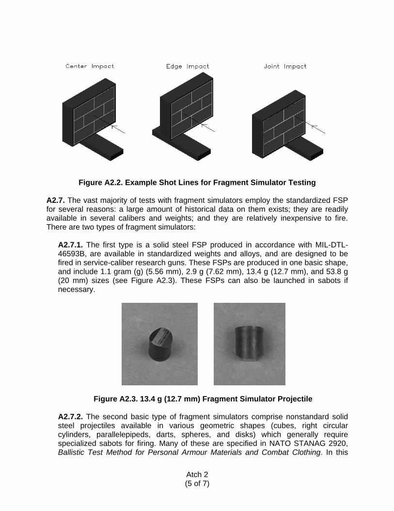
Figure A2.2. Example Shot Lines for Fragment Simulator Testing A2.7. The vast majority of tests with fragment simulators employ the standardized FSP for several reasons: a large amount of historical data on them exists; they are readily available in several calibers and weights; and they are relatively inexpensive to fire. There are two types of fragment simulators:
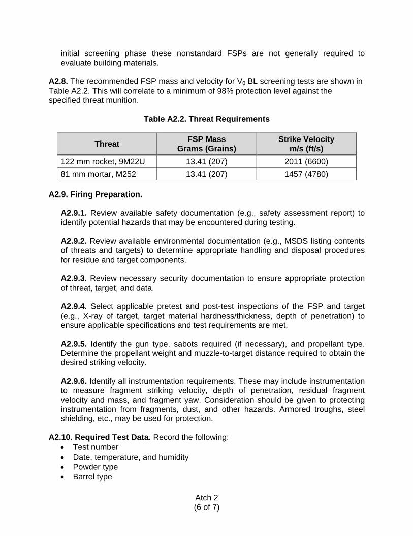
A2.7.1. The first type is a solid steel FSP produced in accordance with MIL-DTL-46593B, are available in standardized weights and alloys, and are designed to be fired in service-caliber research guns. These FSPs are produced in one basic shape, and include 1.1 gram (g) (5.56 mm), 2.9 g (7.62 mm), 13.4 g (12.7 mm), and 53.8 g (20 mm) sizes (see Figure A2.3). These FSPs can also be launched in sabots if necessary.
Figure A2.3. 13.4 g (12.7 mm) Fragment Simulator Projectile A2.7.2. The second basic type of fragment simulators comprise nonstandard solid steel projectiles available in various geometric shapes (cubes, right circular cylinders, parallelepipeds, darts, spheres, and disks) which generally require specialized sabots for firing. Many of these are specified in NATO STANAG 2920, Ballistic Test Method for Personal Armour Materials and Combat Clothing. In this
Atch 2 (6 of 7)
initial screening phase these nonstandard FSPs are not generally required to evaluate building materials.
A2.8. The recommended FSP mass and velocity for V0 BL screening tests are shown in Table A2.2. This will correlate to a minimum of 98% protection level against the specified threat munition.
Table A2.2. Threat Requirements
Threat FSP Mass Grams (Grains)
Strike Velocity m/s (ft/s)
122 mm rocket, 9M22U 13.41 (207) 2011 (6600) 81 mm mortar, M252 13.41 (207) 1457 (4780)
A2.9. Firing Preparation.
A2.9.1. Review available safety documentation (e.g., safety assessment report) to identify potential hazards that may be encountered during testing. A2.9.2. Review available environmental documentation (e.g., MSDS listing contents of threats and targets) to determine appropriate handling and disposal procedures for residue and target components. A2.9.3. Review necessary security documentation to ensure appropriate protection of threat, target, and data. A2.9.4. Select applicable pretest and post-test inspections of the FSP and target (e.g., X-ray of target, target material hardness/thickness, depth of penetration) to ensure applicable specifications and test requirements are met. A2.9.5. Identify the gun type, sabots required (if necessary), and propellant type. Determine the propellant weight and muzzle-to-target distance required to obtain the desired striking velocity. A2.9.6. Identify all instrumentation requirements. These may include instrumentation to measure fragment striking velocity, depth of penetration, residual fragment velocity and mass, and fragment yaw. Consideration should be given to protecting instrumentation from fragments, dust, and other hazards. Armored troughs, steel shielding, etc., may be used for protection.
A2.10. Required Test Data. Record the following:
• Test number • Date, temperature, and humidity • Powder type • Barrel type
Atch 2 (7 of 7)
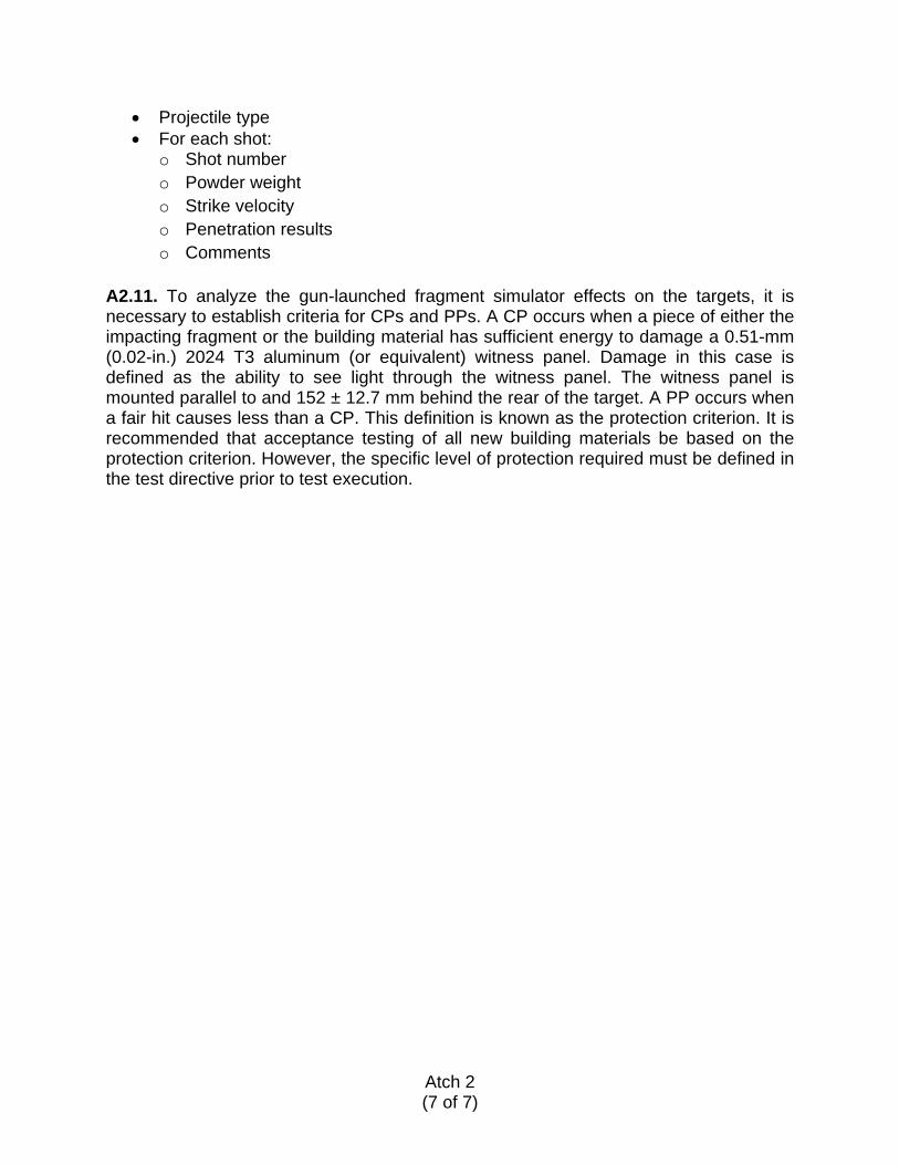
• Projectile type • For each shot:
o Shot number o Powder weight o Strike velocity o Penetration results o Comments
A2.11. To analyze the gun-launched fragment simulator effects on the targets, it is necessary to establish criteria for CPs and PPs. A CP occurs when a piece of either the impacting fragment or the building material has sufficient energy to damage a 0.51-mm (0.02-in.) 2024 T3 aluminum (or equivalent) witness panel. Damage in this case is defined as the ability to see light through the witness panel. The witness panel is mounted parallel to and 152 ± 12.7 mm behind the rear of the target. A PP occurs when a fair hit causes less than a CP. This definition is known as the protection criterion. It is recommended that acceptance testing of all new building materials be based on the protection criterion. However, the specific level of protection required must be defined in the test directive prior to test execution.
Atch 3 (1 of 4)
PRESSURE DATA
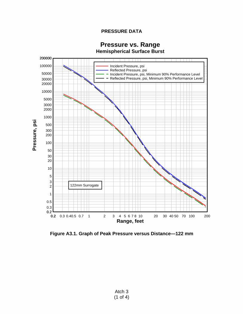
Figure A3.1. Graph of Peak Pressure versus Distance—122 mm
Range, feet
Pres
sure
, psi
Pressure vs. RangeHemispherical Surface Burst
0.20.2 0.3 0.40.5 0.7 1 2 3 4 5 6 7 8 10 20 30 40 50 70 100 2000.20.20.30.5
1
235
10
203050
100
200300500
1000
200030005000
10000
200003000050000
100000
200000200000
122mm Surrogate
Incident Pressure, psiReflected Pressure, psiIncident Pressure, psi, Minimum 90% Performance LevelReflected Pressure, psi, Minimum 90% Performance Level
Atch 3 (2 of 4)
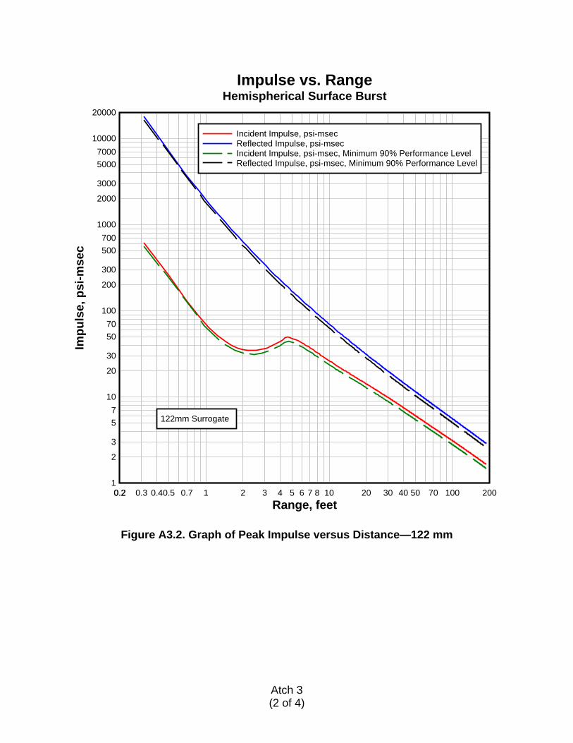
Figure A3.2. Graph of Peak Impulse versus Distance—122 mm
Range, feet
Impu
lse,
psi
-mse
cImpulse vs. Range
Hemispherical Surface Burst
0.20.2 0.3 0.40.5 0.7 1 2 3 4 5 6 7 8 10 20 30 40 50 70 100 2001
2
3
57
10
20
30
5070
100
200
300
500700
1000
2000
3000
50007000
10000
20000
122mm Surrogate
Incident Impulse, psi-msecReflected Impulse, psi-msecIncident Impulse, psi-msec, Minimum 90% Performance LevelReflected Impulse, psi-msec, Minimum 90% Performance Level
Atch 3 (3 of 4)
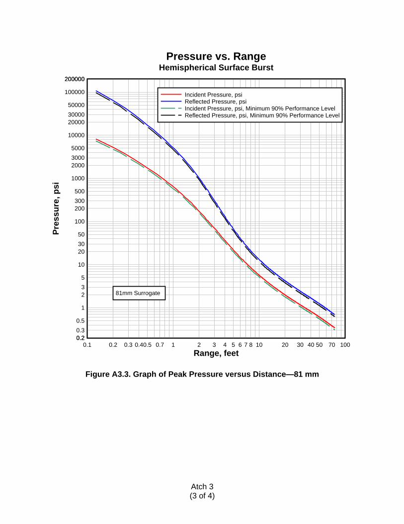
Figure A3.3. Graph of Peak Pressure versus Distance—81 mm
Range, feet
Pres
sure
, psi
Pressure vs. RangeHemispherical Surface Burst
0.1 0.2 0.3 0.40.5 0.7 1 2 3 4 5 6 7 8 10 20 30 40 50 70 1000.20.20.30.5
1
235
10
203050
100
200300500
1000
200030005000
10000
200003000050000
100000
200000200000
81mm Surrogate
Incident Pressure, psiReflected Pressure, psiIncident Pressure, psi, Minimum 90% Performance LevelReflected Pressure, psi, Minimum 90% Performance Level
Atch 3 (4 of 4)
Figure A3.4. Graph of Peak Impulse versus Distance—81 mm
Range, feet
Impu
lse,
psi
-mse
cImpulse vs. Range
Hemispherical Surface Burst
0.1 0.2 0.3 0.40.5 0.7 1 2 3 4 5 6 7 8 10 20 30 40 50 70 1000.50.7
1
2
3
57
10
20
30
5070
100
200
300
500700
1000
2000
3000
50007000
10000
81mm Surrogate
Incident Impulse, psi-msecReflected Impulse, psi-msecIncident Impulse, psi-msec, Minimum 90% Performance LevelReflected Impulse, psi-msec, Minimum 90% Performance Level

Atch 4 (1 of 1)
DISTRIBUTION LIST SPECIAL INTEREST ORGANIZATIONS Information Handling Services (1) Construction Criteria Database (1) 15 Inverness Way East National Institute of Bldg Sciences Englewood, CO 80150 Washington, DC 20005