Embed Size (px)
Citation preview
CAUTION: This DRAFT document is provided for information and is for future development work within the ETSI
Technical Committee TISPAN only. ETSI and its Members accept no liability for any further use/implementation
of this Specification.
Approved and published Specifications and reports for implementation of the TISPAN NGN system shall be
obtained exclusively via the ETSI Documentation Service at http://pda.etsi.org/pda/queryform.asp
ETSI TR 187 002 V3.1.2 (2011-06)
Technical Report
Telecommunications and Internet converged Services andProtocols for Advanced Networking (TISPAN);
TISPAN NGN Security (NGN_SEC);Threat, Vulnerability and Risk Analysis

ETSI
ETSI TR 187 002 V3.1.2 (2011-06) 2
Reference RTR/TISPAN-07037-NGN-R3
Keywords analysis, security
ETSI
650 Route des Lucioles F-06921 Sophia Antipolis Cedex - FRANCE
Tel.: +33 4 92 94 42 00 Fax: +33 4 93 65 47 16
Siret N° 348 623 562 00017 - NAF 742 C
Association à but non lucratif enregistrée à la Sous-Préfecture de Grasse (06) N° 7803/88
Important notice
Individual copies of the present document can be downloaded from: http://www.etsi.org
The present document may be made available in more than one electronic version or in print. In any case of existing or perceived difference in contents between such versions, the reference version is the Portable Document Format (PDF).
In case of dispute, the reference shall be the printing on ETSI printers of the PDF version kept on a specific network drive within ETSI Secretariat.
Users of the present document should be aware that the document may be subject to revision or change of status. Information on the current status of this and other ETSI documents is available at
http://portal.etsi.org/tb/status/status.asp
If you find errors in the present document, please send your comment to one of the following services: http://portal.etsi.org/chaircor/ETSI_support.asp
Copyright Notification
No part may be reproduced except as authorized by written permission. The copyright and the foregoing restriction extend to reproduction in all media.
© European Telecommunications Standards Institute 2011.
All rights reserved.
DECTTM, PLUGTESTSTM, UMTSTM, TIPHONTM, the TIPHON logo and the ETSI logo are Trade Marks of ETSI registered for the benefit of its Members.
3GPPTM is a Trade Mark of ETSI registered for the benefit of its Members and of the 3GPP Organizational Partners. LTE™ is a Trade Mark of ETSI currently being registered
for the benefit of its Members and of the 3GPP Organizational Partners. GSM® and the GSM logo are Trade Marks registered and owned by the GSM Association.
ETSI
ETSI TR 187 002 V3.1.2 (2011-06) 3
Contents
Intellectual Property Rights ................................................................................................................................ 9
Foreword ............................................................................................................................................................. 9
1 Scope ...................................................................................................................................................... 10
2 References .............................................................................................................................................. 10
2.1 Normative references ....................................................................................................................................... 10
2.2 Informative references ...................................................................................................................................... 10
3 Definitions and abbreviations ................................................................................................................. 15
3.1 Definitions ........................................................................................................................................................ 15
3.2 Abbreviations ................................................................................................................................................... 15
4 NGN-relevant Security Interfaces and Scenarios ................................................................................... 17
4.1 Security-relevant NGN Scenarios .................................................................................................................... 17
4.1.1 Basic NGN scenario (ECN&S model) ........................................................................................................ 17
4.1.2 IMS scenarios ............................................................................................................................................. 18
4.1.2.1 3GPP IMS ............................................................................................................................................. 18
4.1.2.2 Generic or NGN IMS ............................................................................................................................ 19
4.1.3 Nomadic user security scenario .................................................................................................................. 21
5 Threat and risk analysis .......................................................................................................................... 21
5.1 PES Analysis .................................................................................................................................................... 21
5.1.1 PES objectives and security objectives ....................................................................................................... 21
5.1.2 Stage 2 model of PES (UML) ..................................................................................................................... 22
5.1.2.1 Identification of assets ........................................................................................................................... 23
5.1.2.2 Missing considerations in PES .............................................................................................................. 23
5.1.2.2.1 ECN technology .............................................................................................................................. 23
5.1.2.2.2 Protocol stack .................................................................................................................................. 24
5.1.2.2.3 Cardinality of relationships ............................................................................................................. 24
5.1.2.2.4 Deployment ..................................................................................................................................... 24
5.1.3 Points of attack in PES................................................................................................................................ 24
5.1.3.1 Interfaces ............................................................................................................................................... 24
5.1.3.2 Implicit relationships ............................................................................................................................. 24
5.1.4 Risk analysis ............................................................................................................................................... 25
5.1.4.1 Overview ............................................................................................................................................... 25
5.1.4.2 Interception ........................................................................................................................................... 25
5.1.4.2.1 Interception at the customer to MGW interface .............................................................................. 25
5.1.4.2.2 Interception within the fixed network .............................................................................................. 25
5.1.4.3 Manipulation ......................................................................................................................................... 25
5.1.4.3.1 Manipulation at the customer interface ........................................................................................... 26
5.1.4.3.2 Manipulation in the fixed parts of the network ................................................................................ 26
5.1.4.3.3 Manipulation in links between networks ......................................................................................... 27
5.1.4.4 Denial-of-Service .................................................................................................................................. 27
5.1.5 PES unwanted incidents .............................................................................................................................. 28
5.1.6 Existing PES security provisions ................................................................................................................ 28
5.1.7 Security capabilities in PES ........................................................................................................................ 28
5.1.7.1 H.248 ETSI_ARGW ............................................................................................................................. 28
5.1.7.1.1 Authentication ................................................................................................................................. 28
5.1.7.1.2 Confidentiality of signalling ............................................................................................................ 28
5.1.7.1.3 Confidentiality of traffic .................................................................................................................. 28
5.1.7.1.4 Integrity of signalling ...................................................................................................................... 29
5.1.7.1.5 Integrity of traffic ............................................................................................................................ 29
5.1.8 Role of NGN subsystems in PES ................................................................................................................ 29
5.1.8.1 Transport plane ..................................................................................................................................... 29
5.1.8.1.1 NASS ............................................................................................................................................... 29
5.1.8.1.2 RACS .............................................................................................................................................. 29
5.1.8.1.3 Transport elements .......................................................................................................................... 29

ETSI
ETSI TR 187 002 V3.1.2 (2011-06) 4
5.1.8.2 Service plane ......................................................................................................................................... 29
5.1.8.2.1 IMS .................................................................................................................................................. 29
5.1.8.2.2 PSS .................................................................................................................................................. 29
5.1.8.3 Recommendations ................................................................................................................................. 29
5.2 Analysis of NASS ............................................................................................................................................ 29
5.3 Analysis of RACS ............................................................................................................................................ 29
5.4 Analysis of NGN-IMS ...................................................................................................................................... 30
5.5 Analysis of DNS and ENUM in NGN.............................................................................................................. 30
5.6 Analysis of SIP in NGN ................................................................................................................................... 30
6 Conclusions for NGN-R1 ....................................................................................................................... 30
Annex A: TVRA of RACS in NGN-R2 ................................................................................................. 33
A.1 Scope of the TVRA ................................................................................................................................ 33
A.2 Identification of the ToE ........................................................................................................................ 33
A.2.1 Overview .......................................................................................................................................................... 33
A.2.2 Scenarios for analysis and derivation of ToE ................................................................................................... 35
A.2.2.1 Summary ..................................................................................................................................................... 35
A.2.2.2 Single trust domain deployment scenario ................................................................................................... 35
A.2.2.3 Two separate trust domains deployment scenario ...................................................................................... 36
A.2.2.4 Two collaborating trust domains deployment scenario............................................................................... 37
A.2.2.5 Multi trust domain deployment scenarios ................................................................................................... 38
A.3 Analysis of ToE elements....................................................................................................................... 39
A.3.1 Transport processing functions ......................................................................................................................... 39
A.3.2 SPDF ................................................................................................................................................................ 40
A.3.3 RACF ............................................................................................................................................................... 40
A.3.4 Reference points ............................................................................................................................................... 40
A.3.5 Information flow analysis ................................................................................................................................. 41
A.4 Security objectives ................................................................................................................................. 45
A.5 Threats to RACS and threat agents to enable them ................................................................................ 46
A.6 Countermeasures for risk mitigation in RACS ....................................................................................... 47
A.6.1 Functional requirements ................................................................................................................................... 47
A.6.2 Detail requirements .......................................................................................................................................... 48
Annex B: TVRA of Media transport NGN-R2 .................................................................................... 49
B.1 Description of ToE ................................................................................................................................. 49
B.2 Identification of objectives ..................................................................................................................... 51
B.3 Step 2: Identification of requirements .................................................................................................... 51
Annex C: Example TVRA for use of ENUM in NGN ......................................................................... 54
C.1 Overview and introduction ..................................................................................................................... 54
C.1.1 Security critical ENUM operations .................................................................................................................. 56
C.1.1.1 Registration of an E.164 number in the ENUM database ........................................................................... 56
C.1.1.2 Processes for creation, modification and deletion of NAPTR Records in the Tier 2 database ................... 57
C.1.1.3 Processes for removal of E.164 numbers from ENUM databases .............................................................. 58
C.1.1.4 Processes for changing Registrars .............................................................................................................. 59
C.1.2 ENUM assets .................................................................................................................................................... 60
C.1.2.1 NAPTR records .......................................................................................................................................... 60
C.1.2.2 ENUM query .............................................................................................................................................. 60
C.2 DNSSEC................................................................................................................................................. 60
C.3 Unwanted incidents in use of ENUM in NGN (eTVRA Step 1) ............................................................ 61
C.4 Security requirements for ENUM in the NGN (eTVRA Step 2) ........................................................... 61
C.5 ENUM assets (eTVRA Step 3) .............................................................................................................. 63
C.5.1 NNA provisioning scenario .............................................................................................................................. 63
ETSI
ETSI TR 187 002 V3.1.2 (2011-06) 5
C.5.2 Signalling scenario ........................................................................................................................................... 64
C.5.3 Identification of assets ...................................................................................................................................... 65
C.5.4 Logical Assets .................................................................................................................................................. 66
C.5.5 Physical Assets ................................................................................................................................................. 66
C.5.6 Summary of assets ............................................................................................................................................ 67
C.5.7 Relationships between assets ............................................................................................................................ 68
C.6 Vulnerabilities in ENUM (eTVRA Step 4) ............................................................................................ 69
C.6.1 Weakness in ENUM (eTVRA Step 4a) ............................................................................................................ 69
C.6.2 Threat agents in ENUM (eTVRA Step 4b) ...................................................................................................... 70
C.6.3 Identification of vulnerabilities in ENUM (eTVRA Step 4.1) ......................................................................... 71
C.7 Risk assessment for ENUM (eTVRA Step 5) ........................................................................................ 72
C.8 ENUM risk classification (eTVRA Step 6) ............................................................................................ 73
C.9 ENUM countermeasure framework (eTVRA Step 7) ............................................................................ 75
C.10 Completed eTVRA proforma for ENUM............................................................................................... 77
Annex D: TVRA of IPTV in NGN-R2 .................................................................................................. 80
D.1 Step 0: Description of ToE (IPTV) ........................................................................................................ 80
D.1.1 IPTV stakeholders ............................................................................................................................................ 80
D.2 Step 1: Identification of objectives ......................................................................................................... 82
D.2.1 Void .................................................................................................................................................................. 82
D.2.2 (System) Security Objectives ........................................................................................................................... 82
D.2.2.1 Security objective category authentication ................................................................................................. 82
D.2.2.2 Security objective category accountability ................................................................................................. 83
D.2.2.3 Security objective category confidentiality ................................................................................................. 83
D.2.2.4 Security objective category integrity .......................................................................................................... 83
D.2.2.5 Security objective category availability ...................................................................................................... 83
D.3 Step 2: Identification of requirements .................................................................................................... 83
D.3.1 Security requirements category authentication ................................................................................................. 83
D.3.2 Security requirement category accountability .................................................................................................. 84
D.3.3 Security requirement category confidentiality.................................................................................................. 85
D.3.4 Security requirement category integrity ........................................................................................................... 86
D.3.5 Security requirement category availability: ...................................................................................................... 86
D.4 Step 3: Inventory of the assets ................................................................................................................ 87
Annex E: TVRA of NAT and NAT-T in NGN-R2 .............................................................................. 88
E.1 Step 0: Description of NAT and NAT-T in NGN-R2 ............................................................................ 88
E.2 Step 1: Identification of objectives ......................................................................................................... 90
E.2.1 (System) Security Objectives ........................................................................................................................... 90
E.3 Step 2: Identification of requirements .................................................................................................... 91
E.4 Step 3: Inventory of the assets ................................................................................................................ 94
E.5 Vulnerabilities in R2 NAT traversal (eTVRA Step 4) ........................................................................... 95
E.5.1 Weakness in R2 NAT traversal (eTVRA Step 4a) ........................................................................................... 95
E.5.2 Threat agents in R2 NAT traversal (eTVRA Step 4b)...................................................................................... 95
E.6 Threats to NAT-T and threat agents to enable them (TVRA steps 4 and 5) .......................................... 96
E.6.1 Identification of threats and threat agents in STUN ......................................................................................... 96
E.6.1.1 Manipulation threats and threat agents ....................................................................................................... 96
E.6.1.1.1 Attacker in NAT-T path ........................................................................................................................ 96
E.6.1.1.1.1 Interception of STUN messages. ..................................................................................................... 96
E.6.1.1.1.2 Manipulation of STUN messages. ................................................................................................... 96
E.6.1.1.1.3 Construction of integrity check value .............................................................................................. 97
E.6.1.1.1.4 Manipulation of STUN protocol ...................................................................................................... 97
E.6.1.1.2 Attacker in NAT-T endpoint ................................................................................................................. 98
E.6.1.2 STUN usage attacks .................................................................................................................................... 98
ETSI
ETSI TR 187 002 V3.1.2 (2011-06) 6
E.6.1.2.1 DDoS Against a Target ......................................................................................................................... 98
E.6.1.2.2 Silencing a Client .................................................................................................................................. 98
E.6.1.2.3 Masquerade as a known Client .............................................................................................................. 98
E.6.1.2.4 Eavesdropping ....................................................................................................................................... 98
E.6.1.2.5 Risk analysis for use of ICE .................................................................................................................. 99
E.6.1.2.6 Risk analysis for use of Outbound ........................................................................................................ 99
E.6.2 Risk analysis for use of IMS-ALG ........................................................................................................ 99
Annex F: TVRA of UC in NGN-R2 .................................................................................................... 100
Annex G: TVRA of CPN in NGN-R3 ................................................................................................. 101
G.1 Customer Premises Network (CPN) Threat Vulnerability and Risk Analysis (TVRA) ...................... 101
G.2 Identification of CPN for TVRA analysis ............................................................................................ 101
G.2.1 Overall description of the CPN ...................................................................................................................... 101
G.2.2 The security analysis process ......................................................................................................................... 101
G.2.2.1 Initial security analysis ............................................................................................................................. 102
G.2.2.2 Assumptions ............................................................................................................................................. 102
G.2.2.3 Security Objectives ................................................................................................................................... 103
G.2.2.4 Security functional requirements derived from the security objectives .................................................... 104
G.2.2.5 Mapping from objectives to functional requirements ............................................................................... 105
G.2.3 Identification of the ToE ................................................................................................................................ 107
G.2.3.1 Inherent weakness in the ToE ................................................................................................................... 108
G.2.3.2 Assets inside the ToE ................................................................................................................................ 108
G.2.3.2.1 Decomposition of the CNG functional entities ................................................................................... 110
G.2.4 Mapping of functional requirements to assets in the ToE .............................................................................. 114
G.2.5 Weaknesses of assets in the ToE .................................................................................................................... 115
G.2.5.1 Wireless access devices ............................................................................................................................ 115
G.2.5.1.1 Wireless Ethernet (IEEE 802.11 series) .............................................................................................. 115
G.2.5.1.1.1 Wired Equivalent Privacy (WEP) .................................................................................................. 115
G.2.5.1.1.2 WiFi Protected Access (WPA) ...................................................................................................... 116
G.2.5.1.1.3 WPA-2 or Robust Security Network (RSN) .................................................................................. 116
G.2.5.1.2 DECT devices ..................................................................................................................................... 116
G.2.5.1.3 Bluetooth devices ................................................................................................................................ 116
G.2.5.2 SIP signalling ............................................................................................................................................ 117
G.2.5.3 Lack of DoS Protection ............................................................................................................................. 117
G.2.5.4 Summary of ToE weaknesses ................................................................................................................... 117
G.2.6 Threats to the weaknesses of assets in the ToE .............................................................................................. 119
G.2.6.1 Denial of service (DoS) ............................................................................................................................ 120
G.2.6.2 Eavesdropping .......................................................................................................................................... 120
G.2.6.2.1 Eavesdropping of content of communication ...................................................................................... 120
G.2.6.2.2 Eavesdropping of network element IDs .............................................................................................. 121
G.2.6.3 Masquerade ............................................................................................................................................... 121
G.2.6.4 Unauthorized access ................................................................................................................................. 122
G.2.6.5 Loss of information ................................................................................................................................... 122
G.2.6.6 Corruption of information ......................................................................................................................... 122
G.2.6.7 Repudiation ............................................................................................................................................... 123
G.2.6.8 Threat list .................................................................................................................................................. 123
G.2.7 Risk factor calculation .................................................................................................................................... 129
G.3 Countermeasures in the form of detailed requirements ........................................................................ 131
G.3.1 General countermeasures ............................................................................................................................... 131
G.3.1.1 Wireless connection measures (CND to CNG) ......................................................................................... 131
G.3.1.2 Connection measures (CNG to NGN) ...................................................................................................... 131
G.3.1.3 Anti-masquerade countermeasures ........................................................................................................... 131
G.3.2 Detailed security requirements ....................................................................................................................... 135
G.3.2.1 Confidentiality requirements .................................................................................................................... 135
G.3.2.2 Identification, authentication and authorization requirements .................................................................. 135
G.3.2.3 Integrity requirements ............................................................................................................................... 135
G.3.2.4 Availability and DoS protection requirements .......................................................................................... 136
Annex H: Identity and privacy protection TVRA for NGN-R3 ....................................................... 137
ETSI
ETSI TR 187 002 V3.1.2 (2011-06) 7
Annex I: TVRA of NASS in NGN-R3 ............................................................................................... 138
I.1 Scope of NASS TVRA ......................................................................................................................... 138
I.2 NASS TVRA Target of Evaluation (ToE) ........................................................................................... 138
I.2.1 Definitions ...................................................................................................................................................... 138
I.2.2 ToE Description ............................................................................................................................................. 139
I.2.3 Analysis of Interfaces ..................................................................................................................................... 140
I.2.4 Assumptions on the ToE ................................................................................................................................ 142
I.2.5 Assumptions of the ToE Environment ........................................................................................................... 142
I.2.6 Revised NASS architecture ............................................................................................................................ 142
I.2.7 Analysis of exposed interfaces ....................................................................................................................... 143
I.3 NASS security objectives ..................................................................................................................... 144
I.4 Functional security requirements ......................................................................................................... 145
I.5 NASS Assets ........................................................................................................................................ 145
I.6 NASS Vulnerabilities and Threats ....................................................................................................... 145
I.6.1 Threat identification and risk analysis of scenarios 10-12 (e1) ...................................................................... 146
I.6.1.1 Implicit line authentication and IP configuration using DHCP over e1 .................................................... 146
I.6.1.1.1 Vulnerabilities and threats ................................................................................................................... 147
I.6.1.2 Explicit authentication over e1 ................................................................................................................. 147
I.6.1.2.1 PPP-based Authentication ................................................................................................................... 147
I.6.1.2.1.1 Vulnerabilities and threats ............................................................................................................. 148
I.6.1.2.2 EAPOL (EAP over Ethernet) Authentication...................................................................................... 148
I.6.1.2.2.1 Vulnerabilities and threats ............................................................................................................. 148
I.6.1.2.3 Explicit authentication over xDSL/FTTx ............................................................................................ 148
I.6.1.2.3.1 Vulnerabilities and threats ............................................................................................................. 149
I.6.1.2.4 WLAN-based authentication ............................................................................................................... 149
I.6.1.2.4.1 Vulnerabilities and threats ............................................................................................................. 150
I.6.1.2.5 NASS-IMS bundled authentication ..................................................................................................... 150
I.6.1.2.5.1 Overview ....................................................................................................................................... 150
I.6.1.2.5.2 Stage 2 model of NASS-IMS bundled authentication ................................................................... 150
I.6.1.2.5.3 NASS-IMS-bundled authentication assets .................................................................................... 151
I.6.1.2.5.4 Uncertainty regarding functions in NASS ..................................................................................... 152
I.6.1.2.5.5 Vulnerabilities and threats ............................................................................................................. 153
I.6.1.3 IP address allocation over e1 .................................................................................................................... 153
I.6.1.3.1 Vulnerabilities and threats ................................................................................................................... 153
I.6.1.4 Risk analysis ............................................................................................................................................. 153
I.6.1.5 Countermeasure framework as detailed requirements .............................................................................. 153
I.6.2 Threat identification and risk analysis of scenario 1 (e5) ............................................................................... 154
I.6.2.1 Overview of interface e5 ........................................................................................................................... 154
I.6.2.2 Protocols and profiles for interface e5 ...................................................................................................... 155
I.6.2.2.1 802.1X-based Authentication .............................................................................................................. 155
I.6.2.2.2 Subscriber Profile Transfer ................................................................................................................. 156
I.6.2.3 Vulnerabilities and threats ........................................................................................................................ 157
I.6.2.4 Risk analysis ............................................................................................................................................. 158
I.6.2.5 Countermeasure framework as requirements ............................................................................................ 158
I.6.3 Threat identification and risk analysis of scenarios 5-11 (e2) ........................................................................ 159
I.6.3.1 Overview of interface e2 ........................................................................................................................... 159
I.6.3.2 Vulnerabilities and threats ........................................................................................................................ 160
I.6.3.3 Risk analysis ............................................................................................................................................. 161
I.6.3.4 Countermeasure framework as requirements ............................................................................................ 162
I.7 Risk Analysis ........................................................................................................................................ 162
I.8 Countermeasure framework as detailed requirements ......................................................................... 163
I.9 Mapping NASS Countermeasure Framework to TS 187 001 .............................................................. 163
I.10 TS 187 001 requirements aligned with NASS countermeasure framework ......................................... 164
I.10.1 WLAN requirements ...................................................................................................................................... 164
I.10.2 AAAA requirements....................................................................................................................................... 164
ETSI
ETSI TR 187 002 V3.1.2 (2011-06) 8
I.10.3 Identity and secure registration requirements ................................................................................................. 164
I.10.4 Privacy requirements ...................................................................................................................................... 165
I.10.5 Communication, data security and confidentiality requirements ................................................................... 166
I.10.6 Availability and DoS Protection requirements ............................................................................................... 167
I.11 Residual Risk ........................................................................................................................................ 168
I.12 Open issues and topics for further study .............................................................................................. 168
Annex J: Vulnerabilities, Threats and Risks to interface e1 ........................................................... 170
J.1 Risk analysis ......................................................................................................................................... 170
J.1.1 Information Disclosure ................................................................................................................................... 170
J.1.1.1 Interception at the customer interface (e1) ............................................................................................... 170
J.1.1.2 Interception within the access network providers network ....................................................................... 171
J.1.1.3 Countermeasure framework as detailed requirements .............................................................................. 171
J.1.2 Manipulation .................................................................................................................................................. 171
J.1.2.1 Manipulation at the customer interface (e1) ............................................................................................. 171
J.1.2.2 Manipulation within the access network providers network ..................................................................... 172
J.1.2.3 Countermeasure framework as requirements ............................................................................................ 173
J.1.3 IP Address and Identity spoofing ................................................................................................................... 173
J.1.3.1 Risk assessment ........................................................................................................................................ 173
J.1.3.2 Countermeasure framework as requirements ............................................................................................ 174
J.1.4 Invalidation of IP address not signalled ......................................................................................................... 174
J.1.4.1 Risk assessment ........................................................................................................................................ 174
J.1.4.2 Countermeasure framework as requirements ............................................................................................ 175
J.1.5 Denial-of-Service ........................................................................................................................................... 175
J.1.5.1 Risk assessment ........................................................................................................................................ 175
J.1.5.2 Countermeasure framework as requirements ............................................................................................ 176
J.1.6 "line-id poisoning" attack with malicious P-Access-Network-Info ................................................................ 176
J.1.6.1 Risk assessment ........................................................................................................................................ 177
J.1.6.2 Countermeasure framework as requirements ............................................................................................ 177
Annex K: Change history .................................................................................................................... 178
Annex L: Bibliography ........................................................................................................................ 179
History ............................................................................................................................................................ 180

ETSI
ETSI TR 187 002 V3.1.2 (2011-06) 9
Intellectual Property Rights IPRs essential or potentially essential to the present document may have been declared to ETSI. The information pertaining to these essential IPRs, if any, is publicly available for ETSI members and non-members, and can be found in ETSI SR 000 314: "Intellectual Property Rights (IPRs); Essential, or potentially Essential, IPRs notified to ETSI in respect of ETSI standards", which is available from the ETSI Secretariat. Latest updates are available on the ETSI Web server (http://webapp.etsi.org/IPR/home.asp).
Pursuant to the ETSI IPR Policy, no investigation, including IPR searches, has been carried out by ETSI. No guarantee can be given as to the existence of other IPRs not referenced in ETSI SR 000 314 (or the updates on the ETSI Web server) which are, or may be, or may become, essential to the present document.
Foreword This Technical Report (TR) has been produced by ETSI Technical Committee Telecommunications and Internet converged Services and Protocols for Advanced Networking (TISPAN).
ETSI
ETSI TR 187 002 V3.1.2 (2011-06) 10
1 Scope The present document presents the results of the Threat Vulnerability Risk Analysis (TVRA) for the NGN.
The present document follows the method and proforma for carrying out a TVRA defined in TS 102 165-1 [i.4] and incorporates material of the NGN threat and risk analysis herein.
The present document identifies security-relevant interfaces in the NGN, identifies security-relevant scenarios for use in the NGN, analyses NGN in terms of security threats and risks by performing a security threat and risk analysis, and classifies the identified vulnerabilities and the associated risk presented to the NGN.
This threat and risk analysis makes a number of assumptions that are believed to hold for typical deployment scenarios of the NGN.
NOTE 1: Depending on the actual instantiation of the NGN some of the assumptions declared in the present document may not fully hold and this may alter the associated risks.
NOTE 2: Whilst the present document is a technical report it identifies requirements for future work. In all cases these requirements are considered indicative pending their ratification in formal ETSI Technical Specifications within the TISPAN Work Programme.
2 References References are either specific (identified by date of publication and/or edition number or version number) or non-specific. For specific references, only the cited version applies. For non-specific references, the latest version of the reference document (including any amendments) applies.
Referenced documents which are not found to be publicly available in the expected location might be found at http://docbox.etsi.org/Reference.
NOTE: While any hyperlinks included in this clause were valid at the time of publication ETSI cannot guarantee their long term validity.
2.1 Normative references The following referenced documents are necessary for the application of the present document.
Not applicable.
2.2 Informative references The following referenced documents are not necessary for the application of the present document but they assist the user with regard to a particular subject area.
[i.1] ETSI EG 202 387: "Telecommunications and Internet converged Services and Protocols for Advanced Networking (TISPAN); Security Design Guide; Method for application of Common Criteria to ETSI deliverables".
[i.2] ETSI TS 181 005: "Telecommunications and Internet Converged Services and Protocols for Advanced Networking (TISPAN); Service and Capability Requirements".
[i.3] ISO/IEC 13335: "Information technology - Guidelines for the management of IT security".
[i.4] ETSI TS 102 165-1 (V4.2.1): "Telecommunications and Internet converged Services and Protocols for Advanced Networking (TISPAN); Methods and protocols; Part 1: Method and proforma for Threat, Risk, Vulnerability Analysis".
ETSI
ETSI TR 187 002 V3.1.2 (2011-06) 11
[i.5] ETSI ES 282 004: "Telecommunications and Internet converged Services and Protocols for Advanced Networking (TISPAN); NGN Functional Architecture; Network Attachment Sub-System (NASS)".
[i.6] ETSI TS 187 001: "Telecommunications and Internet Converged Services and Protocols for Advanced Networking (TISPAN); NGN SECurity (SEC); Requirements".
[i.7] ETSI TS 187 003: "Telecommunications and Internet converged Services and Protocols for Advanced Networking (TISPAN); NGN Security; Security Architecture".
[i.8] ETSI TR 180 001: "Telecommunications and Internet converged Services and Protocols for Advanced Networking (TISPAN); NGN Release 1; Release definition".
[i.9] ETSI ES 282 002: "Telecommunications and Internet converged Services and Protocols for Advanced Networking (TISPAN); PSTN/ISDN Emulation Sub-system (PES); Functional architecture".
[i.10] ETSI ES 282 003: "Telecommunications and Internet converged Services and Protocols for Advanced Networking (TISPAN); Resource and Admission Control Sub-System (RACS): Functional Architecture".
[i.11] ETSI ES 283 002: "Telecommunications and Internet converged Services and Protocols for Advanced Networking (TISPAN); H.248 Profile for controlling Access and Residential Gateways".
[i.12] ETSI EN 383 001: "Telecommunications and Internet converged Services and Protocols for Advanced Networking (TISPAN); Interworking between Session Initiation Protocol (SIP) and Bearer Independent Call Control (BICC) Protocol or ISDN User Part (ISUP) [ITU-T Recommendation Q.1912.5, modified]".
[i.13] ETSI TS 133 210: " Digital cellular telecommunications system (Phase 2+); Universal Mobile Telecommunications System (UMTS); LTE; 3G security; Network Domain Security (NDS); IP network layer security (3GPP TS 33.210 Release 10)".
[i.14] AS/NZS 4360: "Risk Management".
[i.15] Directive 2002/21/EC of the European Parliament and of the council of 7 March 2002 on a common regulatory framework for electronic communications networks and services (Framework Directive).
[i.16] Directive 2002/58/EC of the European Parliament and of the council of 12 July 2002 concerning the processing of personal data and the protection of privacy in the electronic communications sector (Directive on privacy and electronic communications).
[i.17] ETSI ES 282 001: "Telecommunications and Internet converged Services and Protocols for Advanced Networking (TISPAN); NGN Functional Architecture".
[i.18] IETF RFC 3261: "SIP: Session Initiation Protocol".
[i.19] ETSI TS 133 203: "Digital cellular telecommunications system (Phase 2+); Universal Mobile Telecommunications System (UMTS); 3G security; Access security for IP-based services (3GPP TS 33.203 Release 7)".
[i.20] ETSI TS 133 234: "Universal Mobile Telecommunications System (UMTS); 3G security; Wireless Local Area Network (WLAN) interworking security (3GPP TS 33.234 Release 6)".
[i.21] ITU-T Recommendation H.248: "Gateway control protocol".
[i.22] ETSI TR 102 055: "Telecommunications and Internet converged Services and Protocols for Advanced Networking (TISPAN); ENUM scenarios for user and infrastructure ENUM".
[i.23] ETSI TR 102 420: "Telecommunications and Internet converged Services and Protocols for Advanced Networking (TISPAN); Review of activity on security".
[i.24] IETF RFC 2535: "Domain Name System Security Extensions".

ETSI
ETSI TR 187 002 V3.1.2 (2011-06) 12
[i.25] IETF RFC 3761: "The E.164 to Uniform Resource Identifiers (URI) Dynamic Delegation Discovery System (DDDS) Application (ENUM)".
[i.26] IETF RFC 3403: "Dynamic Delegation Discovery System (DDDS) Part Three: The Domain Name System (DNS) Database".
[i.27] IETF RFC 2915: "The Naming Authority Pointer (NAPTR) DNS Resource Record".
[i.28] Draft-ietf-dnsext-dnssec-protocol-06 (2004): "Protocol Modifications for the DNS Security Extensions".
[i.29] Draft-ietf-dnsext-dnssec-records-08 (2004): "Resource Records for DNS Security Extensions".
[i.30] Draft-ietf-dnsext-dnssec-intro-11 (2004): "DNS Security Introduction and Requirements".
[i.31] ISO/IEC 15408-2: "Information technology - Security techniques - Evaluation criteria for IT security - Part 2: Security functional requirements".
[i.32] ISO/IEC 15408: "Information technology - Security techniques - Evaluation criteria for IT security".
NOTE: When referring to all parts of ISO/IEC 15408 the reference above is used.
[i.33] 3GPP TR 33.803: "3rd Generation Partnership Project; Technical Specification Group Services and System Aspects; Coexistence between TISPAN and 3GPP authentication schemes (Release 7)".
[i.34] ETSI TR 187 011: "Telecommunications and Internet converged Services and Protocols for Advanced Networking (TISPAN); NGN Security; Application of ISO-15408-2 requirements to ETSI standards - guide, method and application with examples".
[i.35] ETSI TS 183 017: "Telecommunications and Internet converged Services and Protocols for Advanced Networking (TISPAN); Resource and Admission Control: DIAMETER protocol for session based policy set-up information exchange between the Application Function (AF) and the Service Policy Decision Function (SPDF); Protocol Specification".
[i.36] IETF RFC 1631: "The IP Network Address Translator (NAT)".
[i.37] IETF RFC 1918: "Address Allocation for Private Internets".
[i.38] IETF RFC 3489: "STUN - Simple Traversal of User Datagram Protocol (UDP) Through Network Address Translators (NATs)".
[i.39] IETF draft, draft-ietf-behave-rfc3489bis-13 (November 2007): "STUN - Simple Traversal of User Datagram Protocol (UDP) Through Network Address Translators (NATs)".
[i.40] IETF draft, draft-ietf-mmusic-ice-19 (October 2007): "Interactive Connectivity Establishment (ICE): A Methodology for Network Address Translator (NAT) Traversal for Offer/Answer Protocols".
[i.41] IETF draft, draft-behave-turn-02 (February 2006): "Obtaining Relay Addresses from Simple Traversal of UDP Through NAT (STUN)".
[i.42] ETSI TR 187 009: "Telecommunications and Internet Converged Services and Protocols for Advanced Networking (TISPAN); Feasibility study of prevention of unsolicited communication in the NGN".
[i.43] ETSI SR 002 211: "Electronic communications networks and services; Candidate list of standards and/or specifications in accordance with Article 17 of Directive 2002/21/EC".
[i.44] ETSI TS 181 016: "Telecommunications and Internet converged Services and Protocols for Advanced Networking (TISPAN); Service Layer Requirements to integrate NGN services and IPTV".

ETSI
ETSI TR 187 002 V3.1.2 (2011-06) 13
[i.45] Directive 95/46/EC Of The European Parliament And Of The Council of 24 October 1995 on the protection of individuals with regard to the processing of personal data and on the free movement of such data.
[i.46] ETSI TS 185 006 (V2.3.1): "Telecommunications and Internet converged Services and Protocols for Advanced Networking (TISPAN); Customer Devices architecture and Reference Points".
[i.47] ETSI TS 185 010: "Telecommunications and Internet converged Services and Protocols for Advanced Networking (TISPAN); Customer Premises Networks: Protocol Specification (Stage 3)".
[i.48] ETSI TS 184 002: "Telecommunications and Internet converged Services and Protocols for Advanced Networking (TISPAN); Identifiers (IDs) for NGN".
[i.49] ETSI ES 283 003: "Telecommunications and Internet converged Services and Protocols for Advanced Networking (TISPAN); IP Multimedia Call Control Protocol based on Session Initiation Protocol (SIP) and Session Description Protocol (SDP) Stage 3 [3GPP TS 24.229 [Release 7], modified]".
[i.50] Void.
[i.51] UK Home Office; R.V.Clark, "Hot Products: understanding, anticipating and reducing demand for stolen goods", ISBN 1-84082-278-3.
[i.52] ETSI TR 187 002 (V1.2.2): "Telecommunications and Internet converged Services and Protocols for Advanced Networking (TISPAN);TISPAN NGN Security (NGN-SEC);Threat, Vulnerability and Risk Analysis".
[i.53] IEEE 802.11 (2007): "Standard for Information technology - Telecommunications and information exchange between systems - Local and metropolitan area networks - Specific requirements: Part 11: Wireless LAN Medium Access Control (MAC) and Physical Layer (PHY) specifications".
[i.54] Void.
[i.55] ETSI TS 187 016: "Telecommunications and Internet converged Services and Protocols for Advanced Networking (TISPAN); NGN Security; Identity Protection (Protection Profile)".
[i.56] ETSI EN 300 392-7: "Terrestrial Trunked Radio (TETRA); Voice plus Data (V+D); Part 7: Security".
[i.57] ISO/IEC 15408-2: " Information technology -- Security techniques -- Evaluation criteria for IT security -- Part 2: Security functional requirements".
[i.58] ETSI TR 121 905: "Digital cellular telecommunications system (Phase 2+); Universal Mobile Telecommunications System (UMTS); LTE; Vocabulary for 3GPP Specifications (3GPP TR 21.905)".
[i.59] ISO/IEC 7498-2: " Information processing systems -- Open Systems Interconnection -- Basic Reference Model -- Part 2: Security Architecture".
[i.60] ETSI TS 183 019 (V2.3.0): "Telecommunications and Internet converged Services and Protocols for Advanced Networking (TISPAN); Network Attachment; User-Network Interface Protocol Definitions".
[i.61] ETSI TS 133 310 (V9.4.0): "Universal Mobile Telecommunications System (UMTS); LTE; Network Domain Security (NDS); Authentication Framework (AF) (3GPP TS 33.310 version 9.4.0 Release 9)".
[i.62] ETSI TS 133 320 (V9.3.0): "Universal Mobile Telecommunications System (UMTS); LTE; Security of Home Node B (HNB) / Home evolved Node B (HeNB) (3GPP TS 33.320 version 9.3.0 Release 9)".
[i.63] IETF RFC 1661: "The Point-to-Point Protocol (PPP)".
[i.64] IETF RFC 3741: "Exclusive XML Canonicalization, Version 1.0".

ETSI
ETSI TR 187 002 V3.1.2 (2011-06) 14
[i.65] IETF RFC 1994: "PPP Challenge Handshake Authentication Protocol (CHAP)".
[i.66] ETSI TS 124 234: "Universal Mobile Telecommunications System (UMTS); LTE; 3GPP system to Wireless Local Area Network (WLAN) interworking; WLAN User Equipment (WLAN UE) to network protocols; Stage 3 (3GPP TS 24.234)".
[i.67] ETSI TS 124 229: "Digital cellular telecommunications system (Phase 2+); Universal Mobile Telecommunications System (UMTS); LTE; IP multimedia call control protocol based on Session Initiation Protocol (SIP) and Session Description Protocol (SDP); Stage 3 (3GPP TS 24.229)".
[i.68] IETF RFC 2617: "HTTP Authentication: Basic and Digest Access Authentication".
[i.69] Void.
[i.70] ETSI TS 183 020: "Telecommunications and Internet converged Services and Protocols for Advanced Networking (TISPAN); Network Attachment: Roaming in TISPAN NGN Network Accesses; Interface Protocol Definition".
[i.71] ETSI TS 129 234: "Universal Mobile Telecommunications System (UMTS); LTE; 3GPP system to Wireless Local Area Network (WLAN) interworking; Stage 3 (3GPP TS 29.234)".
[i.72] IETF RFC 3539: "Authentication, Authorization and Accounting (AAA) Transport Profile".
[i.73] IETF RFC 4005: "Diameter Network Access Server Application".
[i.74] IETF RFC 4072: "Diameter Extensible Authentication Protocol (EAP) Application".
[i.75] IETF RFC 2865: "Remote Authentication Dial In User Service (RADIUS)".
[i.76] IETF RFC 3580: "IEEE 802.1X Remote Authentication Dial In User Service (RADIUS) Usage Guidelines".
[i.77] IETF RFC 3748: "Extensible Authentication Protocol (EAP)".
[i.78] IETF RFC 2548: "Microsoft Vendor-specific RADIUS Attributes".
[i.79] IETF RFC 2866: "RADIUS Accounting".
[i.80] IETF RFC 4372: "Chargeable User Identity".
[i.81] IETF RFC 2486bis(6): "The Network Access Identifier".
[i.82] IETF RFC 3162: "RADIUS and IPv6".
[i.83] IETF RFC 3588: "Diameter Base Protocol".
[i.84] ETSI ES 283 034: "Telecommunications and Internet converged Services and Protocols for Advanced Networking (TISPAN); Network Attachment Sub-System (NASS); e4 interface based on the DIAMETER protocol".
[i.85] ETSI ES 283 035: "Telecommunications and Internet converged Services and Protocols for Advanced Networking (TISPAN); Network Attachment Sub-System (NASS); e2 interface based on the DIAMETER protocol".
[i.86] ETSI TS 129 329: "Digital cellular telecommunications system (Phase 2+); Universal Mobile Telecommunications System (UMTS); LTE; Sh interface based on the Diameter protocol; Protocol details (3GPP TS 29.329)".
[i.87] IETF RFC 3554: "On the Use of Stream Control Transmission Protocol (SCTP) with IPsec".
[i.88] IETF RFC 2960: "Stream Control Transmission Protocol".
[i.89] IETF RFC 3309: "Stream Control Transmission Protocol (SCTP) Checksum Change".
[i.90] IETF RFC 4201: "Link Bundling in MPLS Traffic Engineering (TE)".
[i.91] IETF RFC 4301: "Security Architecture for the Internet Protocol".
ETSI
ETSI TR 187 002 V3.1.2 (2011-06) 15
[i.92] ETSI TR 133 978: "Universal Mobile Telecommunications System (UMTS); Security aspects of early IP Multimedia Subsystem (IMS) (3GPP TR 33.978)".
[i.93] ETSI TS 133 220: "Digital cellular telecommunications system (Phase 2+); Universal Mobile Telecommunications System (UMTS); Generic Authentication Architecture (GAA); Generic bootstrapping architecture (3GPP TS 33.220)".
[i.94] ETSI TS 102 165-2: " Telecommunications and Internet converged Services and Protocols for Advanced Networking (TISPAN); Methods and protocols; Part 2: Protocol Framework Definition; Security Counter Measures"
3 Definitions and abbreviations
3.1 Definitions For the purposes of the present document, the terms and definitions given in EG 202 387 [i.1] and the following apply:
attack: attempt to bypass security controls on a computer
NAT traversal: term used to describe the problem of establishing connections between hosts in IP networks which use NAT devices (either locally or remotely) to modify their local IP address
Network Address Translation: method by which IP addresses are mapped from one realm to another in order to provide transparent routing to hosts
NOTE: NAT devices are used to connect address domains with private (unregistered) addresses to public domains with globally unique (registered) addresses.
T-nnn: numeric identifier for a threat
threat: potential cause of an unwanted incident which may result in harm to a system or organization
NOTE: See ISO/IEC 13335 [i.3].
unwanted incident: incident such as loss of confidentiality, integrity and/or availability
NOTE: See AS/NZS 4360 [i.14].
user equipment: one or more devices allowing a user to access services delivered by TISPAN NGN networks
NOTE: This includes devices when under user control commonly referred to as IAD, ATA, RGW, TE, etc., UE does not include network controlled entities such as network terminations and access gateways.
vulnerability: flaw or weakness in system security procedures, system design, implementation, internal controls, etc., that could be exploited to violate system security policy
NOTE: Vulnerability is often used synonymously with weakness.
3.2 Abbreviations For the purposes of the present document, the following abbreviations apply:
3G 3rd Generation 3GPP 3rd Generation Partnership Project ADSL Asymmetric Digital Subscriber Line AF Application Function AGCF Access Gateway Control Function AGW Access GateWay AH Authentication Header A-MGF Access Media Gateway Function A-RACF Access-Resource and Admission Control Function

ETSI
ETSI TR 187 002 V3.1.2 (2011-06) 16
ARGW Access Residential media GateWay AS Application Server B2BUA Back-To-Back User Agent BGF Border Gateway Function BTF Basic Transport Function CC Call Control CCM Counter mode with Cipher block chaining Message authentication code CCMP Counter mode with Cipher block chaining Message authentication code Protocol CD Compact Disc CHAP Challenge Handshake Authentication Protocol CLF Connectivity session and repository Location Function CND Customer Network Device CNG Customer Network Gateway CPE Customer Premises Equipment CPN Customer Premises Network C-RACF Core-Resource and Admission Control Function CRAVED Concealable, Removable, Available, Valuable, Enjoyable, and Disposable CSCF Call Session Control Function DECT Digital European Cordless telephony DNS Domain Name System DNSSEC DNS SECurity DoS Denial-of-Service DSAA DECT Standard Authentication Algorithm DSC DECT Standard Cipher DTMF Dual Tone Multi Frequency EAP Extensible Authentication Protocol ECN Electronic Communication Network ECN&S Electronic Communications Networks and Services ECS Electronic Communication Service ESP Encapsulating Security Payload FFS For Further Study FQDN Fully Qualified Domain Name GPRS GSM Packet Radio System ICE Interactive Connectivity Establishment I-CSCF Interrogating Call Session Control Function IETF Internet Engineering Task Force IKE Internet Key Exchange IMS IP Multimedia Subsystem IMSI IMS subscriber Identifier IP Internet Protocol IPsec Internet Protocol security IPTV Internet Protocol TeleVision ISDN Integrated Services Digital Network ISIM IMS Subscriber Identity Module ISO International Standards Organization ISUP ISDN User Part IVR Interactive Voice Response MAC Message Authentication Code MD Message Digest MGC Media Gateway Controller MGW Media GateWay MRFP Media Resource Function Processor NANP NGN Access Network Provider NASS Network Access SubSystem NAT (1) Network Address Translator (device) NAT (2) Network Address Translation (process) NAT-T Network Address Translation Traversal NBA NASS-Bundled Authentication NCP NGN Connectivity Provider NGN Next Generation Network NT Network Termination OSI Open Systems Interconnection

ETSI
ETSI TR 187 002 V3.1.2 (2011-06) 17
P-CSCF Proxy Call Session Control Function PDBF Profile Data Base Function PES PSTN/ISDN Emulation Subsystem PNG Public Network Gateway PoC Push to talk over Cellular PS Packet-Switched PSTN Public Switched Telephone Network RACS Resource Admission Control Subsystem RAMR Realistic-Achievable-Mesurable-Relevant RCEF Resource Control Enforcement Function RGW Residential GateWay R-MGF Residential Media Gateway Function ROM Read-Only Memory RSN Robust Security Network RTCP Realtime Transport Control Protocol RTP Realtime Transport Protocol RTSP Real-Time Streaming Protocol S-CSCF Serving Call Session Control Function SDP Session Description Protocol SEG SEcurity Gateway SGW Signalling GateWay SIP Session Initiation Protocol SPDF Service Policy Decision Function SpoA Service point of Attachment STUN Simple Traversal of UDP through NAT TCP Transport Control Protocol TDM Time Division Multiplex TISPAN Telecommunication and Internet converged Services and Protocols for Advanced Networking TKIP Temporal Key Integrity Protocol TLS Transport Layer Security ToE Target of Evaluation TPF Transport Processing Function TpoA Transport point of Attachment TVRA Threat Vulnerability Risk Assessment UAAF User Access Authorization Function UDP User Datagram Protocol UE User Equipment UICC Universal Integrated Circuit Card UML Unified Modelling Language UNI User-Network Interface UPSF User Profile Server Function VLAN Virtual Local Area Network WEP Wired Equivalent Privacy WiFi Wireless Fidelity WLAN Wireless Local Area Network WPA WiFi Protected Access
4 Introduction and overview Threat, Vulnerability and Risk Analysis (TVRA) is the ETSI standard for risk assessment. The TVRA method is described in TS 102 165-1 [i.4] and comprises the following 10 steps:
1) Identification of the Target of Evaluation (ToE) resulting in a high level description of the main assets of the ToE and the ToE environment and a specification of the goal, purpose and scope of the TVRA.
2) Identification of the objectives resulting in a high level statement of the security aims and issues to be resolved.
3) Identification of the functional security requirements, derived from the objectives from step 2.
ETSI
ETSI TR 187 002 V3.1.2 (2011-06) 18
4) Inventory of the assets as refinements of the high level asset descriptions from step 1 and additional assets as a result of steps 2 and 3.
5) Identification and classification of the vulnerabilities in the system, the threats that can exploit them, and the unwanted incidents that may result.
6) Quantifying the occurrence likelihood and impact of the threats.
7) Establishment of the risks.
8) Identification of countermeasures framework (conceptual) resulting in a list of alternative security services and capabilities needed to reduce the risk.
9) Countermeasure cost-benefit analysis (including security requirements cost-benefit analysis depending on the scope and purpose of the TVRA) to identify the best-fitted security services and capabilities amongst alternatives identified in step 8.
10) Specification of detailed requirements for the security services and capabilities identified and described in step 9.
NOTE: Details on the steps and the activities involved are given in TS 102 165-1 [i.4].
This document describes the result of TVRA of the NGN, its associated subsystems, interfaces and core protocols.
5 NGN TVRA
This clause documents the NGN TVRA. The analysis contains and overall description of the NGN, outline the NGN subsystems and documents the NGN general threats and risks. The NGN is divided into a number of subsystems and make use of a set of core protocols. The TVRA of the NGN subsystems and core protocols are documented in separate annexes.
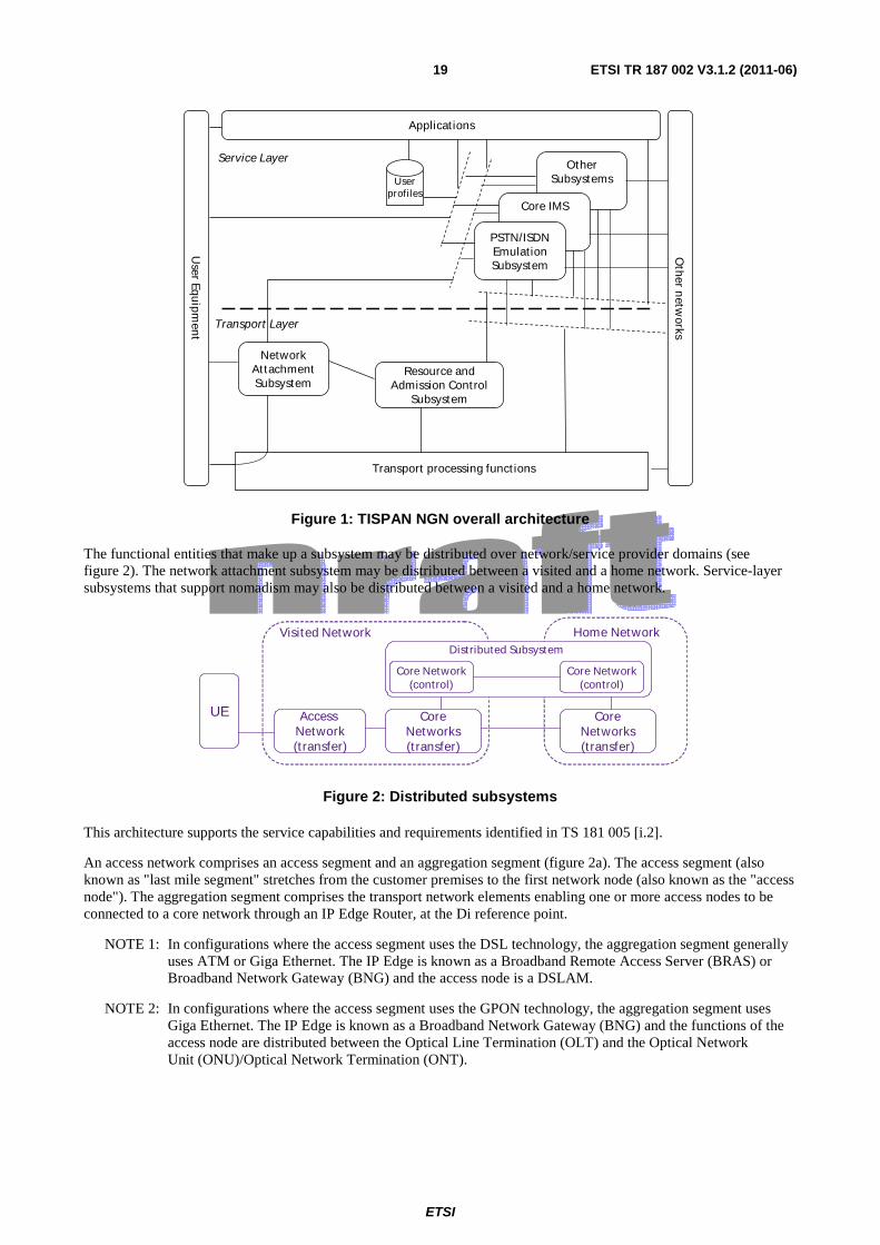
5.1 Overview of NGN The NGN functional architecture is described in ES 282 001 [i.17]. The NGN architecture complies with the ITU-T general reference model for next generation and is structured according to a service layer and an IP-based transport layer.
The service layer comprises the following components:
• the core IP Multimedia Subsystem (IMS);
• the PSTN/ISDN Emulation Subsystem (PES);
• other multimedia subsystems (e.g. IPTV Dedicated Subsystem) and applications;
• common components (i.e. used by several subsystems) such as those required for accessing applications, charging functions, user profile management, security management, routing data bases (e.g. ENUM), etc.
This subsystem-oriented architecture enables the addition of new subsystems over the time to cover new demands and service classes. It also provides the ability to import (and adapt) subsystems defined by other standardization bodies.
IP-connectivity is provided to NGN user equipment by the transport layer, under the control of the Network Attachment SubSystem (NASS) and the Resource and Admission Control Subsystem (RACS). These subsystems hide the transport technology used in access and core networks below the IP layer.
Figure 1 provides an overview of the NGN architecture.
ETSI
ETSI TR 187 002 V3.1.2 (2011-06) 19
Other Subsystems
Core IMS
PSTN/ISDNEmulationSubsystem
User Equ
ipment
Service Layer
Transport processing funct ions
Resource and Admission Control
Subsystem
Applicat ions
Userprofiles
Transport Layer
Network Attachment Subsystem
Other n
etworks
Figure 1: TISPAN NGN overall architecture
The functional entities that make up a subsystem may be distributed over network/service provider domains (see figure 2). The network attachment subsystem may be distributed between a visited and a home network. Service-layer subsystems that support nomadism may also be distributed between a visited and a home network.
CoreNetworks(t ransfer)
Access Network(t ransfer)
UE
Visited Network Home Network
CoreNetworks(t ransfer)
Core Network(control)
Core Network(control)
Dist ributed Subsystem
Figure 2: Distributed subsystems
This architecture supports the service capabilities and requirements identified in TS 181 005 [i.2].
An access network comprises an access segment and an aggregation segment (figure 2a). The access segment (also known as "last mile segment" stretches from the customer premises to the first network node (also known as the "access node"). The aggregation segment comprises the transport network elements enabling one or more access nodes to be connected to a core network through an IP Edge Router, at the Di reference point.
NOTE 1: In configurations where the access segment uses the DSL technology, the aggregation segment generally uses ATM or Giga Ethernet. The IP Edge is known as a Broadband Remote Access Server (BRAS) or Broadband Network Gateway (BNG) and the access node is a DSLAM.
NOTE 2: In configurations where the access segment uses the GPON technology, the aggregation segment uses Giga Ethernet. The IP Edge is known as a Broadband Network Gateway (BNG) and the functions of the access node are distributed between the Optical Line Termination (OLT) and the Optical Network Unit (ONU)/Optical Network Termination (ONT).
ETSI
ETSI TR 187 002 V3.1.2 (2011-06) 20
AccessNode
IP-EdgeTransport Network ElementsU
ser
Equ
ipm
ent
Access Segment Aggregation Segment
Cor
e N
etw
ork
Di
Figure 3: Access and aggregation segments
5.2 Security-relevant NGN Scenarios Scenarios are presented following a complexity ordering, from a simple generic model to rather more complex scenarios.
5.2.1 Basic NGN scenario (ECN&S model)
The Electronic Communication Network (ECN) and Electronic Communication Service (ECS) model as shown in figure 4 is the model used in the Framework Directive [i.15] and simplifies the network into a set of provision types. An ECN is a communication network and roughly speaking addresses the lowest 3 layers of the ISO/OSI protocol stack. An ECS is a communication service and roughly speaking addresses the highest layers of the ISO/OSI stack. In order to connect a user connects to both an ECS and an ECN.
The basic model shows that the CPE may consist of more than one equipment type and that the NT has two connection points, one for services (SpoA) and one for Transport (or network) (TpoA).
Figure 4: Basic ECN&S model for the NGN
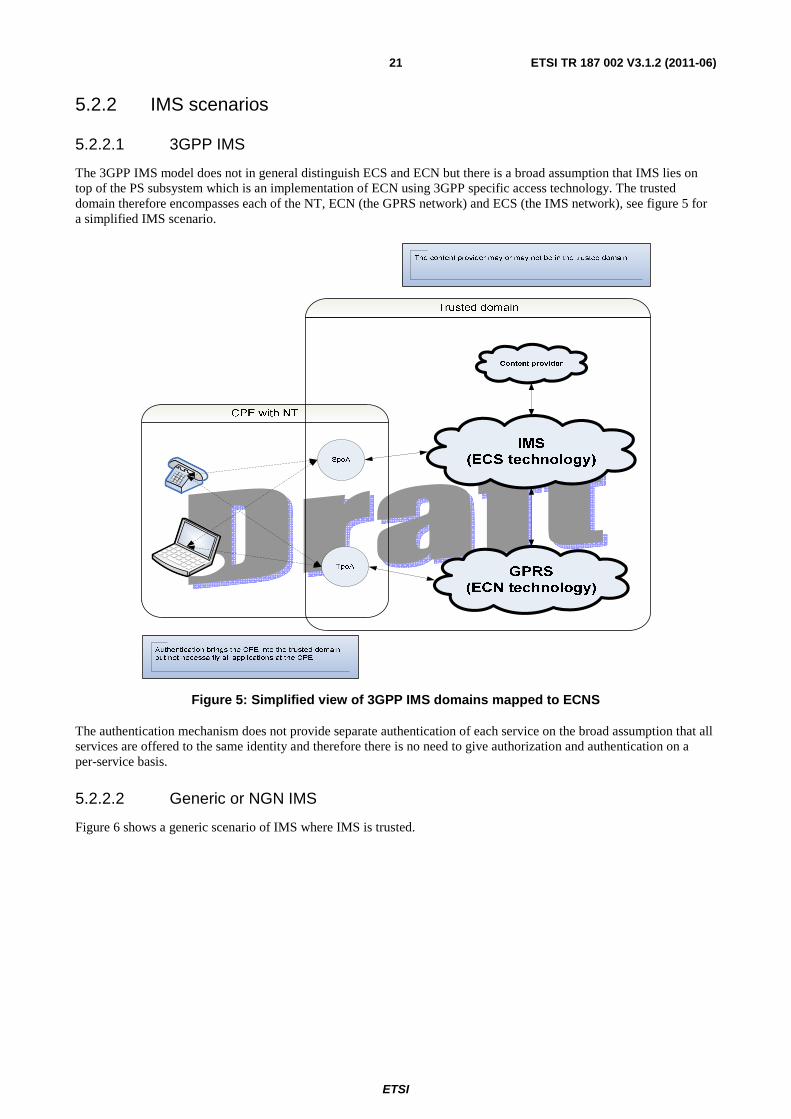
ETSI
ETSI TR 187 002 V3.1.2 (2011-06) 21
5.2.2 IMS scenarios
5.2.2.1 3GPP IMS
The 3GPP IMS model does not in general distinguish ECS and ECN but there is a broad assumption that IMS lies on top of the PS subsystem which is an implementation of ECN using 3GPP specific access technology. The trusted domain therefore encompasses each of the NT, ECN (the GPRS network) and ECS (the IMS network), see figure 5 for a simplified IMS scenario.
Figure 5: Simplified view of 3GPP IMS domains mapped to ECNS
The authentication mechanism does not provide separate authentication of each service on the broad assumption that all services are offered to the same identity and therefore there is no need to give authorization and authentication on a per-service basis.
5.2.2.2 Generic or NGN IMS
Figure 6 shows a generic scenario of IMS where IMS is trusted.
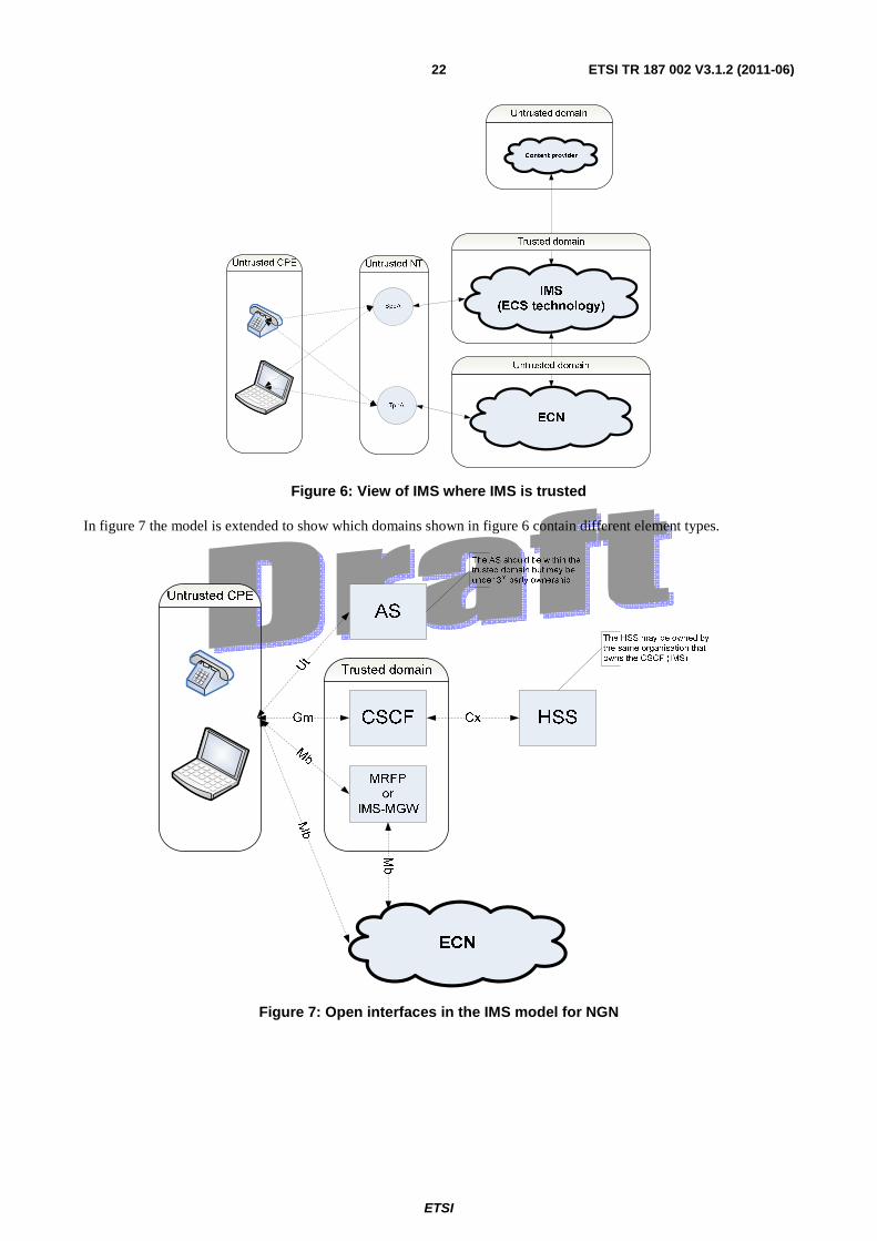
ETSI
ETSI TR 187 002 V3.1.2 (2011-06) 22
Figure 6: View of IMS where IMS is trusted
In figure 7 the model is extended to show which domains shown in figure 6 contain different element types.
Figure 7: Open interfaces in the IMS model for NGN
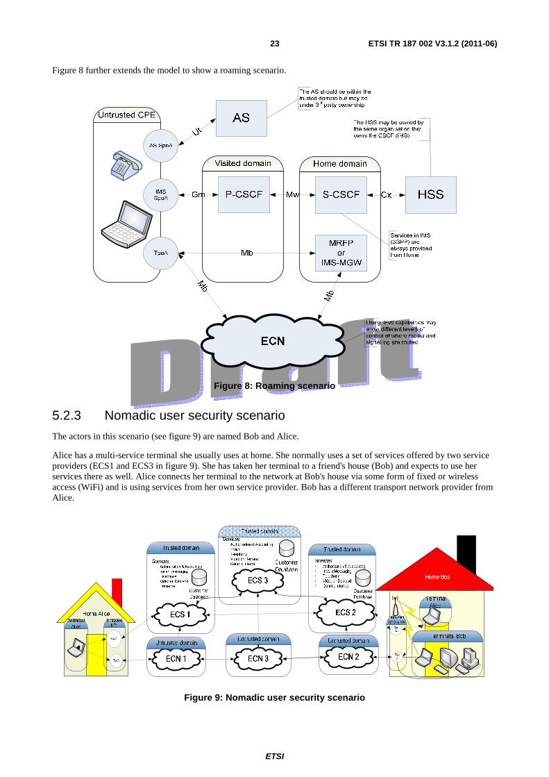
ETSI
ETSI TR 187 002 V3.1.2 (2011-06) 23
Figure 8 further extends the model to show a roaming scenario.
Figure 8: Roaming scenario
5.2.3 Nomadic user security scenario
The actors in this scenario (see figure 9) are named Bob and Alice.
Alice has a multi-service terminal she usually uses at home. She normally uses a set of services offered by two service providers (ECS1 and ECS3 in figure 9). She has taken her terminal to a friend's house (Bob) and expects to use her services there as well. Alice connects her terminal to the network at Bob's house via some form of fixed or wireless access (WiFi) and is using services from her own service provider. Bob has a different transport network provider from Alice.
Figure 9: Nomadic user security scenario
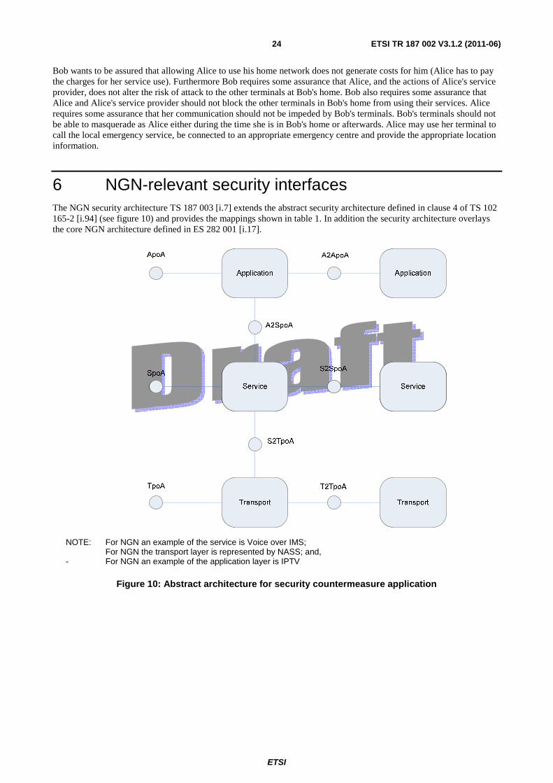
ETSI
ETSI TR 187 002 V3.1.2 (2011-06) 24
Bob wants to be assured that allowing Alice to use his home network does not generate costs for him (Alice has to pay the charges for her service use). Furthermore Bob requires some assurance that Alice, and the actions of Alice's service provider, does not alter the risk of attack to the other terminals at Bob's home. Bob also requires some assurance that Alice and Alice's service provider should not block the other terminals in Bob's home from using their services. Alice requires some assurance that her communication should not be impeded by Bob's terminals. Bob's terminals should not be able to masquerade as Alice either during the time she is in Bob's home or afterwards. Alice may use her terminal to call the local emergency service, be connected to an appropriate emergency centre and provide the appropriate location information.
6 NGN-relevant security interfaces The NGN security architecture TS 187 003 [i.7] extends the abstract security architecture defined in clause 4 of TS 102 165-2 [i.94] (see figure 10) and provides the mappings shown in table 1. In addition the security architecture overlays the core NGN architecture defined in ES 282 001 [i.17].
NOTE: For NGN an example of the service is Voice over IMS; For NGN the transport layer is represented by NASS; and, - For NGN an example of the application layer is IPTV
Figure 10: Abstract architecture for security countermeasure application
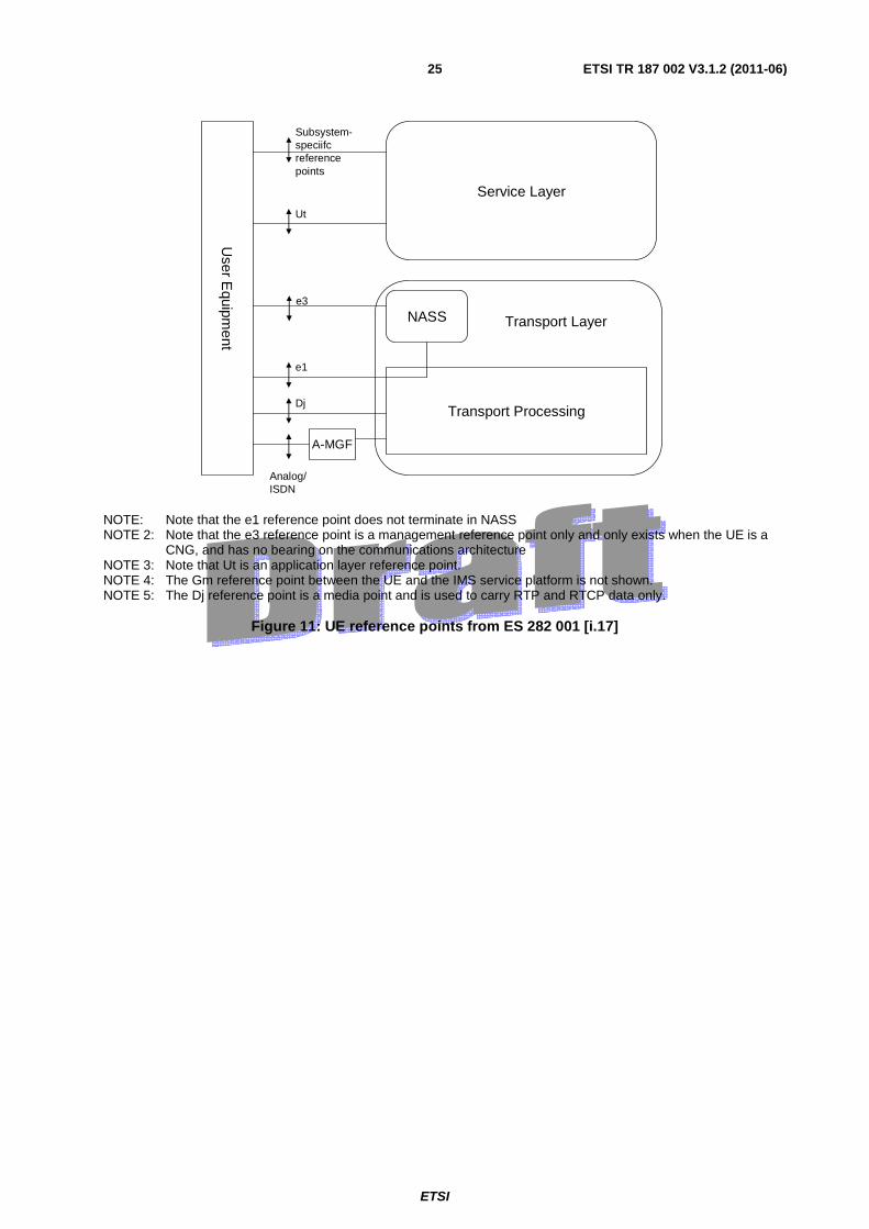
ETSI
ETSI TR 187 002 V3.1.2 (2011-06) 25
User E
quipment
NASS
Transport Processing
e1
Dj
Service Layer
e3
Ut
Subsystem-speciifc reference points
Transport Layer
Analog/ISDN
A-MGF
NOTE: Note that the e1 reference point does not terminate in NASS NOTE 2: Note that the e3 reference point is a management reference point only and only exists when the UE is a
CNG, and has no bearing on the communications architecture NOTE 3: Note that Ut is an application layer reference point. NOTE 4: The Gm reference point between the UE and the IMS service platform is not shown. NOTE 5: The Dj reference point is a media point and is used to carry RTP and RTCP data only.
Figure 11: UE reference points from ES 282 001 [i.17]

ETSI
ETSI TR 187 002 V3.1.2 (2011-06) 26
Table 1: Mapping from TS 102 165-2 abstract reference points to NGN architecture
Abstract
reference
point
(from TS
102 165-2
[i.94])
NGN reference
point
Security service
building block
defined
Authentication
principal
Location of
security
association
definition
SEGF applies at
Za
(TS 133 210 [i.13])
(see note 3)
TpoA e1 Authentication
Confidentiality
Integrity
Key management
Network Access
Identifier (NAI)
IEEE 802.1x as
defined in TS 183
019 [20] (Note 1)
No
Dj n/a
Z n/a
ST n/a
SpoA Gm Authentication
Confidentiality
Integrity
Key management
IMSI, IMPU TS 133 203 [7]
(Note 2)
No
ApoA Ut No
T2TpoA e5 Authentication
Confidentiality
Integrity
Key management
Yes
Iz n/a
S2SpoA Yes
A2ASpoA Yes
A2SpoA Yes
S2TpoA e2 Authentication
Confidentiality
Integrity
Key management
TS 283 035 [21] Yes
Gq' Authentication
Confidentiality
Integrity
Key management
TS 183 017 [35] Yes
NOTE 1: IEEE 802.1x is defined for use to secure Ethernet access and makes the assumption that the NASS architecture (see ES 282 004) is modified to combine the ARF/AMF to the authenticator function and the UAAF/SPDF acting as the authentication server.
NOTE 2: TS 133 203 provides support for a number of authentication schemes including SIP/HTTP-digest and the NASS bundled options (i.e. authentication at NASS is accepted by IMS without invoking any IMS specific authentication functions).
NOTE 3: A SEGF is used where the domains are discrete and is mandatory for all exposed inter-domain interfaces providing integrity and confidentiality of signalling content with source address authentication. Connections between the different NGN components within the same NGN network are the "Zb" interfaces. These interfaces are mandatory for implemenation and optional for use, depending on operator risk assesment
The following reference points are wholly within the transport domain and are not exposed:

ETSI
ETSI TR 187 002 V3.1.2 (2011-06) 27
• a1, a2, a3, a4 and thus are assumed to be in the security domain of the transport domain
The following reference points are wholly within the service domain and are not exposed:
• none
The NGN architecture is described by the following elements:
• NGN security domains
• NGN Security services (see the mappings given in table 1):
• NGN Security protocols supporting the security services
In addition the security architecture endorses Security Gateways (SEGs) defined by TS 133 210 [i.13] and renames them for the NGN application as Security Gateway Function (SEGF) to secure signalling and control communication among network entities/FEs.
In addition tosecurity domains the NGN security architecture also defines logical security planes across multiple domains supporting the abstract model of figure mapped to specific NGN functionality:
• Transport instantiated in the NASS security plane;
• Service instantiated in the IMS security plane;
• Application instantiated in the GAA/GBA key management plane.
NOTE 1: The terminology of V-UUAF and H-UAAF is not consistent with that used in the NASS stage 2 document ES 282 004 where the terms UAAF Proxy and UAAF Server are used.
NOTE 2: The interface Zh between BSF and UPSF is defined in 3GPP but not endorsed in TISPAN NGN. NOTE 3: No functional decomposition of UPSF, PDPF and HSS has been carried out therefore any sharing of
functionality between these elements is not considered in the current version of the document. NOTE 4: In the IMS the HSS and UPSF functions overlap.
Figure 12: Usage of security FEs in the NGN security architecture
For NASS an authentication security association shall be established between the UE and the PDPF/H-UAAF. The NASS principal shall be the NAI with the role of authenticator being taken by the PDPF/H-UAAF.
NOTE: It is assumed that the PDPF hold the credentials for authentication of the NASS with the H-UAAF carrying out the authentication process.
The NASS security plane encompasses the security operations during network attachment for gaining access to the NGN access network. The visited UAAF (V-UAAF) in a visited access network relays authentication message to/from the home NGN network (equivalent in operation to the VSS or VLR in PLMN); the V-UAAF (if present) may be a proxy while the home UAAF (H-UAAF) shall process the authentication message and decide authorization (equivalent in operation to the HSS or HLR in PLMN). The H-UAAF takes into account user profile information that is stored in the PDBF (equivalent to the Authentication Centre in PLMN). The PDBF shall hold the profiles of the NASS user.
ETSI
ETSI TR 187 002 V3.1.2 (2011-06) 28
NOTE 1: In the NGN, an IMS subscriber may register over an IP access session established by a NASS subscriber, which may not be the same as the IMS subscriber. In such cases there is no relation between the profile/credentials used at the NASS level and at the IMS level.
NOTE 2: The PDBF may be co-located with the UPSF.
NOTE 3: The dashed lines between H-UAAF and PDBF and between the NAS/AS and the UPSF indicate interfaces which are not defined in the present document.
For IMS the required security associations are defined by TS 133 203 [i.19] and the procedures defined therein shall apply. The UPSF shall hold the user profiles used at the IMS level.The GBA/GAA security plane encompasses the NAF and BSF FEs for application layer security.
NOTE: The TISPAN Application Server (AS) could have access to BSF as described in TS 133 220 [i.93] in which case UPSF takes the role of the HSS and has a connection to the BSF through reference points Zn and Zh.
7 NGN core protocols. Editor´s Note: Insert an overview of the NGN core protocols (SIP, DIAMETER, RADIUS) and refer to the annex
containing the relevant analysis. Note that the TVRA of SIP, DIAMETER and RADIUS has not been performed.
8 Conclusion and summary for NGN-R3. Editor´s Note: Insert a table summarizing the outstanding risks of NGN.
9 Threat and risk analysis
9.1 Analysis of PES See annex K of the present document.
9.2 Analysis of NASS See annex I of the present document.
9.3 Analysis of RACS See annex A of the present document.
9.4 Analysis of NGN-IMS FFS.
9.5 Analysis of DNS and ENUM in NGN See annex C of the present document.
ETSI
ETSI TR 187 002 V3.1.2 (2011-06) 29
9.6 Analysis of CPN See annex G of the present document.
9.7 Analysis of Media Transport in NGN See annex B of the present document.
9.8 Analysis of IPTV in NGN See annex D of the present document.
9.9 Analysis of NAT and NAT-T in NGN See annex E in the present document.
9.10 Analysis of UC in NGN See annex F in the present document.
9.11 Analysis of identity and privay protection in NGN See annex H in the present document.
9.12 Analysis of SIP in NGN Void
9.13 Analysis of DIAMETER in NGN Void
9.14 Analysis of RADIUS in NGN Void
9.15 Analysis of SIP in NGN Void
9.16 Analysis of DIAMETER in NGN

ETSI
ETSI TR 187 002 V3.1.2 (2011-06) 30
9.17 Analysis of RADIUS in NGN Void.
ETSI
ETSI TR 187 002 V3.1.2 (2011-06) 31
Annex A: TVRA of RACS in NGN-R2 Void
Editor's note: Removed from this as it cannot be guaranteed that the analysis still stands in NGN-R3.

ETSI
ETSI TR 187 002 V3.1.2 (2011-06) 32
Annex B: TVRA of Media transport NGN-R2 Void
Editor's note: Removed from this as it cannot be guaranteed that the analysis still stands in NGN-R3.

ETSI
ETSI TR 187 002 V3.1.2 (2011-06) 33
Annex C: TVRA for use of ENUM in NGN Void
Editor's note: Removed from this as it cannot be guaranteed that the analysis still stands in NGN-R3.

ETSI
ETSI TR 187 002 V3.1.2 (2011-06) 34
Annex D: TVRA of IPTV in NGN-R2 Void
Editor's note: Removed from this as it cannot be guaranteed that the analysis still stands in NGN-R3.

ETSI
ETSI TR 187 002 V3.1.2 (2011-06) 35
Annex E: TVRA of NAT and NAT-T in NGN-R2 Void
Editor's note: Removed from this as it cannot be guaranteed that the analysis still stands in NGN-R3.

ETSI
ETSI TR 187 002 V3.1.2 (2011-06) 36
Annex F: TVRA of UC in NGN-R2 Void
Editor's note: Removed from this as it cannot be guaranteed that the analysis still stands in NGN-R3.
ETSI
ETSI TR 187 002 V3.1.2 (2011-06) 37
Annex G: TVRA of CPN in NGN-R3
NOTE: Whilst the present document is a technical report it identifies requirements for future work as a direct consequence of the analysis and should not be interpreted as mandates in the scope of the present document. In all cases these requirements are considered indicative pending their ratification in formal ETSI Technical Specifications within the TISPAN Work Programme.
G.10 Customer Premises Network (CPN) Threat Vulnerability and Risk Analysis (TVRA)
Risk analysis based security provision is at the heart of the "design for assurance" approach adopted in TISPAN to security standards development. In the NGN environment a Customer Premises Network is a loosely managed entity in the customer premises equipment offering both local services and connectivity (e.g. connecting the PCs, media centres, gaming platforms, printers and other ICT equipment of the household) and offering a gateway to the services of the NGN from the household.
The present document provides the documented output of the TVRA exercise performed against the CPN as defined in TISPAN WG5.
The content of the present document is intended to drive solutions for securing the CPN in the context of the NGN.
G.11 Identification of CPN for TVRA analysis
G.11.1 Overall description of the CPN The Customer Premises Network (CPN) offers a subset of NGN functionality within the domain of the subscriber whilst also allowing full access to the NGN by terminal/client emulation. In simple terms the CPN comprises a number of user terminals, referred to as Customer Network Devices (CNDs), connected to a Customer Network Gateway (CNG) which provides local routing, local services and access to the NGN.
There are a large number of technologies that may be used to connect CNDs to the CNG and the current analysis includes due consideration of how to apply some of the security capabilities of these to the abstract technologies of the modelled CPN.
NOTE: Existing home ADSL devices may share some of the functionality of CNGs and the set of devices in existing home networks may share some of the functionality of CPNs but should not be considered as NGN CPNs as defined by ETSI.
A CPN is intended to operate in a low cost and low maintenance environment and these factors have been taken into consideration in the preparation of the security recommendations made in the present document.
G.11.2 The security analysis process The security analysis follows the process described in TS 102 165-1 [i.4] as illustrated below.
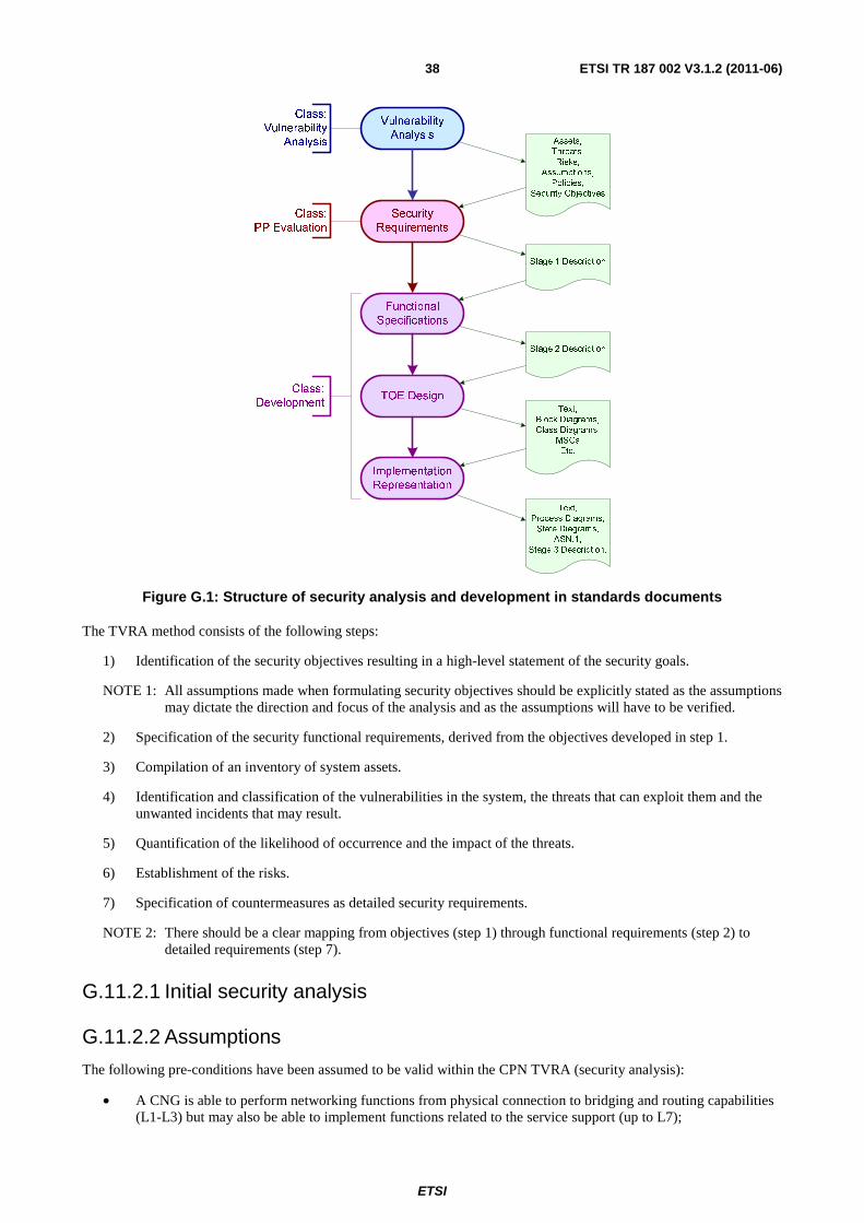
ETSI
ETSI TR 187 002 V3.1.2 (2011-06) 38
Vulnerability
Analysis
Security
Requirements
Functional
Specifications
TOE Design
Implementation
Representation
Class:
Vulnerability
Analysis
Class:
PP Evaluation
Class:
Development
Assets,
Threats,
Risks,
Assumptions,
Policies,
Security Objectives
Stage 1 Description
Stage 2 Description
Text,
Block Diagrams,
Class Diagrams,
MSCs
Etc.
Text,
Process Diagrams,
State Diagrams,
ASN.1,
Stage 3 Description.
Figure G.1: Structure of security analysis and development in standards documents
The TVRA method consists of the following steps:
1) Identification of the security objectives resulting in a high-level statement of the security goals.
NOTE 1: All assumptions made when formulating security objectives should be explicitly stated as the assumptions may dictate the direction and focus of the analysis and as the assumptions will have to be verified.
2) Specification of the security functional requirements, derived from the objectives developed in step 1.
3) Compilation of an inventory of system assets.
4) Identification and classification of the vulnerabilities in the system, the threats that can exploit them and the unwanted incidents that may result.
5) Quantification of the likelihood of occurrence and the impact of the threats.
6) Establishment of the risks.
7) Specification of countermeasures as detailed security requirements.
NOTE 2: There should be a clear mapping from objectives (step 1) through functional requirements (step 2) to detailed requirements (step 7).
G.11.2.1 Initial security analysis
G.11.2.2 Assumptions
The following pre-conditions have been assumed to be valid within the CPN TVRA (security analysis):
• A CNG is able to perform networking functions from physical connection to bridging and routing capabilities (L1-L3) but may also be able to implement functions related to the service support (up to L7);
ETSI
ETSI TR 187 002 V3.1.2 (2011-06) 39
• The UNI connection to NGN-IMS services is provided at the Gm reference point;
• The Ut reference point may act as a UNI connection to non-IMS NGN services (where the services are in the application server space);
• e3 reference point is used for remote registration to the CPN as described in ETSI TS 185 006 [i.46]
• The CNG may host an application server on behalf of the CND;
• Physical access to either the CND or the CNG to acquire security-related information (for example, the reading of keystroke sequence mechanically) is out of scope for this analysis;
• Where an IMS terminal uses the CNG in "pass through" mode the CNG is considered to be a network controlled access gateway and not a CNG in the normal sense. It is, therefore, out of scope of the CPN analysis;
• A CNG and a network controlled access gateway may co-exist in the same physical hardware but are maintained in separate security domains. This is somewhat similar to a single PC acting both as a database server and as a web server where some attacks on the base hardware or operating system will affect both capabilities equally but attacks specific to the server types will affect only the attacked server type;
• The CNG acts on behalf of the CNDs in communicating with the NGN;
• The CNG is a full NGN terminal with an NGN identity as defined in TS 184 002 [i.48]:
- the NGN is assumed to be protected by a full security association with the CNG created using any specified method including IMS-AKA in order to provide authentication of the CNG-identity, and which may also provide confidentiality of the communications between the CNG and the NGN and protection of the integrity of signalling between the CNG and the NGN
• The CND may be a full NGN terminal with an NGN identity as defined in TS 184 002 [i.48] or a non-NGN terminal attached to the CNG via an appropriate terminal adaptor;
• The CNG only connects to the NGN by a fixed line connection (i.e. not by a UMTS radio connection);
• The NGN does not distinguish between a CNG and any other NGN terminal;
• The NGN includes IMS as a service platform.
• The CNG hardware may allow the coexistence of Public Network Gateway (PNG) services and the CPN CNG service. It is assumed that in this case the CPN-CNG service is distinct from the PNG service.
G.11.2.3 Security Objectives
The security objectives shown in table G.1 are categorized according to the guidelines specified in annex D of TS 187 001 [i.6]. A CPN is comprised of one or more CND and a CNG. As a CND can be any user equipment and is unspecified it is excluded from the CPN security analysis. A CND represents an important threat interface to the CPN and is considered to be an un-trusted entity.
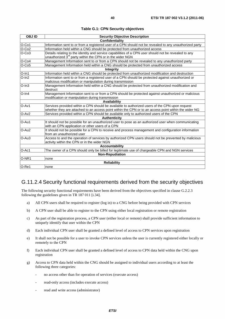
ETSI
ETSI TR 187 002 V3.1.2 (2011-06) 40
Table G.1: CPN Security objectives
OBJ ID Security Objective Description Confidentiality
O-Co1 Information sent to or from a registered user of a CPN should not be revealed to any unauthorized party O-Co2 Information held within a CNG should be protected from unauthorized access O-Co3 Details relating to the identity and service capabilities of a CPN user should not be revealed to any
unauthorized 3rd party within the CPN or in the wider NGN O-Co4 Management Information sent to or from a CPN should not be revealed to any unauthorized party O-Co5 Management Information held within a CNG should be protected from unauthorized access
Integrity O-In1 Information held within a CNG should be protected from unauthorized modification and destruction O-In2 Information sent to or from a registered user of a CPN should be protected against unauthorized or
malicious modification or manipulation during transmission O-In3 Management Information held within a CNG should be protected from unauthorized modification and
destruct O-In4 Management Information sent to or from a CPN should be protected against unauthorized or malicious
modification or manipulation during transmission Availability
O-Av1 Services provided within a CPN should be available to authorized users of the CPN upon request whether they are attached to an access point within the CPN or to an access point within the wider NG
O-Av2 Services provided within a CPN should be available only to authorized users of the CPN Authenticity
O-Au1 It should not be possible for an unauthorized user to pose as an authorized user when communicating with an CPN application or other users of a CPN
O-Au2 It should not be possible for a CPN to receive and process management and configuration information from an unauthorized user
O-Au3 Access to and the operation of services by authorized CPN users should not be prevented by malicious activity within the CPN or in the wider NGN
Accountability O-Ac1 The owner of a CPN should only be billed for legitimate use of chargeable CPN and NGN services
Non-Repudiation O-NR1 none
Reliability O-Re1 none
G.11.2.4 Security functional requirements derived from the security objectives
The following security functional requirements have been derived from the objectives specified in clause G.2.2.3 following the guidelines given in TR 187 011 [i.34].
a) All CPN users shall be required to register (log in) to a CNG before being provided with CPN services
b) A CPN user shall be able to register to the CPN using either local registration or remote registration
c) As part of the registration process, a CPN user (either local or remote) shall provide sufficient information to uniquely identify that user within the CPN
d) Each individual CPN user shall be granted a defined level of access to CPN services upon registration
e) It shall not be possible for a user to invoke CPN services unless the user is currently registered either locally or remotely to the CPN
f) Each individual CPN user shall be granted a defined level of access to CPN data held within the CNG upon registration
g) Access to CPN data held within the CNG should be assigned to individual users according to at least the following three categories:
- no access other than for operation of services (execute access)
- read-only access (includes execute access)
- read and write access (administrator)
ETSI
ETSI TR 187 002 V3.1.2 (2011-06) 41
h) All CPN users who have read-only access or read and write access to CPN data held within the CNG shall be authenticated and authorized as part of the user registration process (whether local registration or remote registration)
i) It shall not be possible for a user who is not currently registered to the CPN to have any access to CPN data held within the CNG
j) As an option, it shall be possible for signalling and media exchanged between the CNG and the NGN to be encrypted
k) As an option, it shall be possible for management information exchanged between the CNG and the NGN to be encrypted
l) A CNG shall implement or activate mechanisms for detecting changes en route to data (signalling and media) exchanged with the NGN
m) A CNG shall implement mechanisms for detecting possible denial-of-service attacks from within the CPN
n) A CNG shall implement mechanisms for detecting possible denial-of-service attacks originating within the NGN
o) All CPN users shall be authenticated by the CNG as part of the user registration process before invoking any NGN services
p) All CPN users shall be authenticated as part of the user registration process before invoking any CPN services
q) The CNG shall assign unique and non-forgeable identities to all CPN sessions that are verifiable to users and to devices
r) For each CPN session a CNG shall maintain a record of the devices and users linked to that CPN session
s) As an option, it shall be possible to record parts of or all outgoing data transmission from a CNG
t) As an option, it shall be possible to record parts of or all incoming data transmission for a CNG
u) As an option, it shall be possible to record parts of or all access to data held within a CNG
v) As an option, it shall be possible to record parts of or all modifications of data held within a CNG
G.11.2.5 Mapping from objectives to functional requirements
TVRA examines the relevant security associations at several abstraction layers. The two upper abstraction layers are security objectives and functional requirements. Functional requirements are the implementation of the security objectives and refine the security associations introduced in the objectives. The relation between the objectives and the functional requirements are the following: one objective may be fulfilled by one or more functional requirements and one functional requirement may address one or more security objectives. To visualize the relations between these security associations, the following table maps each functional requirement to the objective(s) that they address.
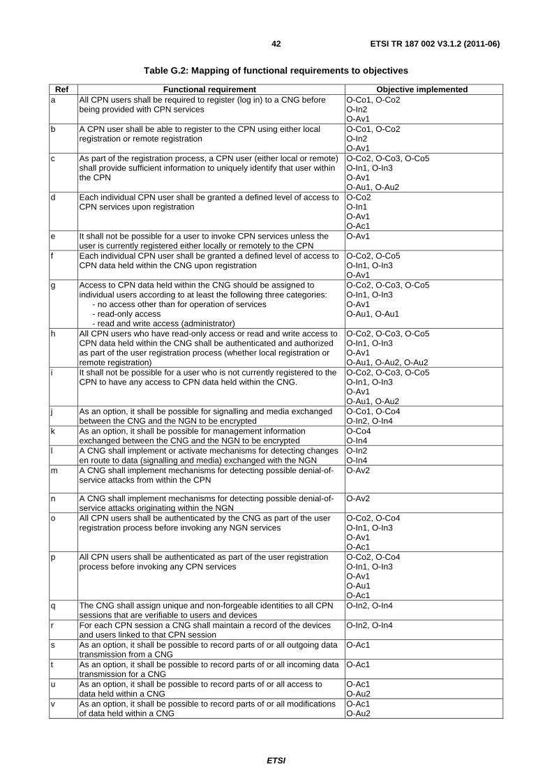
ETSI
ETSI TR 187 002 V3.1.2 (2011-06) 42
Table G.2: Mapping of functional requirements to objectives
Ref Functional requirement Objective implemented a All CPN users shall be required to register (log in) to a CNG before
being provided with CPN services O-Co1, O-Co2 O-In2 O-Av1
b A CPN user shall be able to register to the CPN using either local registration or remote registration
O-Co1, O-Co2 O-In2 O-Av1
c As part of the registration process, a CPN user (either local or remote) shall provide sufficient information to uniquely identify that user within the CPN
O-Co2, O-Co3, O-Co5 O-In1, O-In3 O-Av1 O-Au1, O-Au2
d Each individual CPN user shall be granted a defined level of access to CPN services upon registration
O-Co2 O-In1 O-Av1 O-Ac1
e It shall not be possible for a user to invoke CPN services unless the user is currently registered either locally or remotely to the CPN
O-Av1
f Each individual CPN user shall be granted a defined level of access to CPN data held within the CNG upon registration
O-Co2, O-Co5 O-In1, O-In3 O-Av1
g Access to CPN data held within the CNG should be assigned to individual users according to at least the following three categories: - no access other than for operation of services - read-only access - read and write access (administrator)
O-Co2, O-Co3, O-Co5 O-In1, O-In3 O-Av1 O-Au1, O-Au1
h All CPN users who have read-only access or read and write access to CPN data held within the CNG shall be authenticated and authorized as part of the user registration process (whether local registration or remote registration)
O-Co2, O-Co3, O-Co5 O-In1, O-In3 O-Av1 O-Au1, O-Au2, O-Au2
i It shall not be possible for a user who is not currently registered to the CPN to have any access to CPN data held within the CNG.
O-Co2, O-Co3, O-Co5 O-In1, O-In3 O-Av1 O-Au1, O-Au2
j As an option, it shall be possible for signalling and media exchanged between the CNG and the NGN to be encrypted
O-Co1, O-Co4 O-In2, O-In4
k As an option, it shall be possible for management information exchanged between the CNG and the NGN to be encrypted
O-Co4 O-In4
l A CNG shall implement or activate mechanisms for detecting changes en route to data (signalling and media) exchanged with the NGN
O-In2 O-In4
m A CNG shall implement mechanisms for detecting possible denial-of-service attacks from within the CPN
O-Av2
n A CNG shall implement mechanisms for detecting possible denial-of-service attacks originating within the NGN
O-Av2
o All CPN users shall be authenticated by the CNG as part of the user registration process before invoking any NGN services
O-Co2, O-Co4 O-In1, O-In3 O-Av1 O-Ac1
p All CPN users shall be authenticated as part of the user registration process before invoking any CPN services
O-Co2, O-Co4 O-In1, O-In3 O-Av1 O-Au1 O-Ac1
q The CNG shall assign unique and non-forgeable identities to all CPN sessions that are verifiable to users and devices
O-In2, O-In4
r For each CPN session a CNG shall maintain a record of the devices and users linked to that CPN session
O-In2, O-In4
s As an option, it shall be possible to record parts of or all outgoing data transmission from a CNG
O-Ac1
t As an option, it shall be possible to record parts of or all incoming data transmission for a CNG
O-Ac1
u As an option, it shall be possible to record parts of or all access to data held within a CNG
O-Ac1 O-Au2
v As an option, it shall be possible to record parts of or all modifications of data held within a CNG
O-Ac1 O-Au2
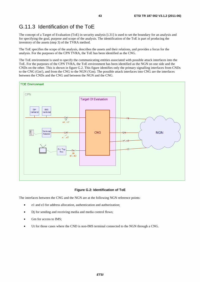
ETSI
ETSI TR 187 002 V3.1.2 (2011-06) 43
G.11.3 Identification of the ToE The concept of a Target of Evaluation (ToE) in security analysis [i.31] is used to set the boundary for an analysis and for specifying the goal, purpose and scope of the analysis. The identification of the ToE is part of producing the inventory of the assets (step 3) of the TVRA method.
The ToE specifies the scope of the analysis, describes the assets and their relations, and provides a focus for the analysis. For the purposes of the CPN TVRA, the ToE has been identified as the CNG.
The ToE environment is used to specify the communicating entities associated with possible attack interfaces into the ToE. For the purposes of the CPN TVRA, the ToE environment has been identified as the NGN on one side and the CNDs on the other. This is shown in figure G.2. This figure identifies only the primary signalling interfaces from CNDs to the CNG (Gm'), and from the CNG to the NGN ('Gm). The possible attack interfaces into CNG are the interfaces between the CNDs and the CNG and between the NGN and the CNG.
Figure G.2: Identification of ToE
The interfaces between the CNG and the NGN are at the following NGN reference points:
• e1 and e3 for address allocation, authentication and authorization;
• Dj for sending and receiving media and media control flows;
• Gm for access to IMS;
• Ut for those cases where the CND is non-IMS terminal connected to the NGN through a CNG.
ETSI
ETSI TR 187 002 V3.1.2 (2011-06) 44
Although there is no requirement for a CND to be an IMS terminal, the CNG offers each CND a range of IMS-like services by connecting through a terminal adapter where necessary. In this way, a CNG is able to provide a signalling connection from the CND to the NGN, thus:
• an IMS CND interfaces directly to the SIP Application Servers in the NGN at the Ut reference point;
• a non-IMS SIP CND interfaces directly to the SIP Application Servers in the NGN at the Ut reference point;
• a CND interfaces with the CNG for configuration and management functions at the e3' reference point;
• a CND interfaces with the CNG for network attachment functions at the e1' reference point;
• a CND interfaces with the CNG for SIP services over the B2BUA at the Gm' reference point.
G.11.3.1 Inherent weakness in the ToE
Analysis of the NGN CPN specifications [i.46], [i.47] has identified the following weaknesses in the CNG:
1) SIP is the primary signalling system used within the CPN and previous studies have demonstrated a number of core weaknesses in the SIP protocol [i.52];
2) SIP is semantically and syntactically imprecise although best practice guidelines have made significant efforts to address these issues;
3) It is possible for the connection between a CND and the CNG to be wireless which would mean that all communication between the CND and the CNG is exposed to interception attack;
4) The physical environment in which the CPN is placed is unlikely to be controlled and thus may open the physical elements of the CPN (the CNDs and the CNG) to theft (it is assumed that all CPN equipment fit the criminal criteria of CRAVED [i.51]);
5) The CNG operates in an un-trusted domain;
6) A home installation of a CPN is unlikely to be protected against interruptions of power or against electromagnetic interference;
7) The CNG connects to the NGN at three distinct logical points (Transport, IMS/Service, Application) and the transport attachment is a normal IP termination it is possible to invoke end-user services directly at the transport layer and by that bypassing any equivalent service normally connected at either the IMS/Service or Application layers.
NOTE: The impact of any attack that exploits this weakness varies from the point of observation of the attack whereas the likelihood is constant.
G.11.3.2 Assets inside the ToE
A functional decomposition of the CNG (the ToE) identifies a number of interoperating entities (assets) as shown in figure G.3.
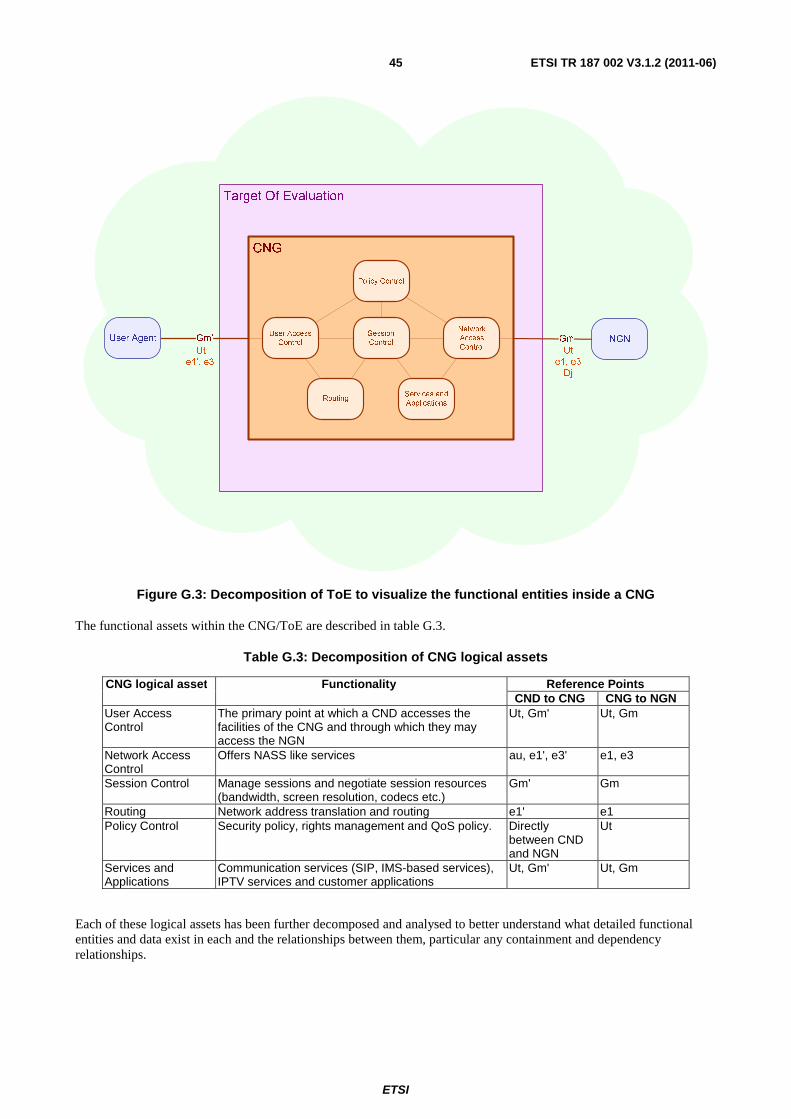
ETSI
ETSI TR 187 002 V3.1.2 (2011-06) 45
Target Of Evaluation
Gm’
CNG
Gm
Services and
Applications
Session
Control
Policy Control
Routing
User Access
Control
Network
Access
ControlUser Agent NGN
Ut
e1’, e3'
Ut
e1, e3
Dj
Figure G.3: Decomposition of ToE to visualize the functional entities inside a CNG
The functional assets within the CNG/ToE are described in table G.3.
Table G.3: Decomposition of CNG logical assets
CNG logical asset Functionality Reference Points CND to CNG CNG to NGN
User Access Control
The primary point at which a CND accesses the facilities of the CNG and through which they may access the NGN
Ut, Gm' Ut, Gm
Network Access Control
Offers NASS like services au, e1', e3' e1, e3
Session Control Manage sessions and negotiate session resources (bandwidth, screen resolution, codecs etc.)
Gm' Gm
Routing Network address translation and routing e1' e1 Policy Control Security policy, rights management and QoS policy. Directly
between CND and NGN
Ut
Services and Applications
Communication services (SIP, IMS-based services), IPTV services and customer applications
Ut, Gm' Ut, Gm
Each of these logical assets has been further decomposed and analysed to better understand what detailed functional entities and data exist in each and the relationships between them, particular any containment and dependency relationships.
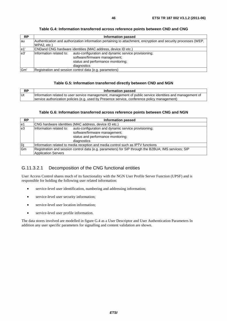
ETSI
ETSI TR 187 002 V3.1.2 (2011-06) 46
Table G.4: Information transferred across reference points between CND and CNG
RP Information passed au Authentication and authorization information pertaining to attachment, encryption and security processes (WEP,
WPA2, etc.) e1' CNDand CNG hardware identities (MAC address, device ID etc.) e3' Information related to: auto-configuration and dynamic service provisioning;
software/firmware management; status and performance monitoring; diagnostics
Gm' Registration and session control data (e.g. parameters)
Table G.5: Information transferred directly between CND and NGN
RP Information passed Ut Information related to user service management, management of public service identities and management of
service authorization policies (e.g. used by Presence service, conference policy management)
Table G.6: Information transferred across reference points between CNG and NGN
RP Information passed e1 CNG hardware identities (MAC address, device ID etc.) e3 Information related to: auto-configuration and dynamic service provisioning;
software/firmware management; status and performance monitoring; diagnostics
Dj Information related to media reception and media control such as IPTV functions Gm Registration and session control data (e.g. parameters) for SIP through the B2BUA; IMS services; SIP
Application Servers
G.11.3.2.1 Decomposition of the CNG functional entities
User Access Control shares much of its functionality with the NGN User Profile Server Function (UPSF) and is responsible for holding the following user related information:
• service-level user identification, numbering and addressing information;
• service-level user security information;
• service-level user location information;
• service-level user profile information.
The data stores involved are modelled in figure G.4 as a User Descriptor and User Authentication Parameters In addition any user specific parameters for signalling and content validation are shown.
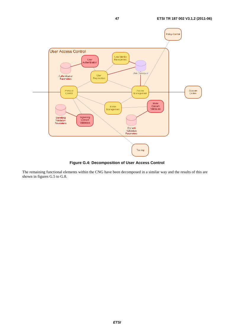
ETSI
ETSI TR 187 002 V3.1.2 (2011-06) 47
Figure G.4: Decomposition of User Access Control
The remaining functional elements within the CNG have been decomposed in a similar way and the results of this are shown in figures G.5 to G.8.
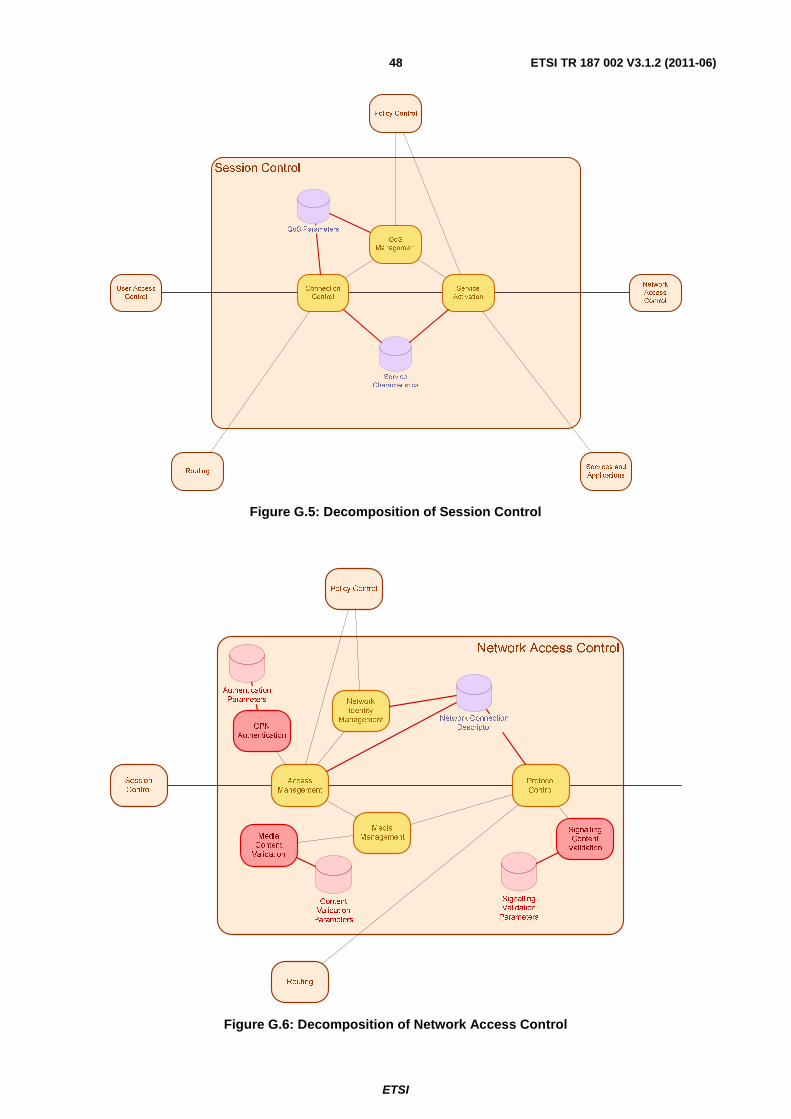
ETSI
ETSI TR 187 002 V3.1.2 (2011-06) 48
Session Control
Service
Activation
Connection
Control
QoS
Management
Services and
Applications
Policy Control
Routing
User Access
Control
Network
Access
Control
Service
Characteristics
QoS Parameters
Figure G.5: Decomposition of Session Control
Network Access Control
Network Identity
Management
Media Management
Policy Control
Routing
Session Control
Protocol Control
Access Management
Signalling Validation
Parameters
Content Validation
Parameters
CPN
Authentication
Signalling Content
Validation
Media Content
Validation
Authentication
Parameters
Network ConnectionDescriptor
Figure G.6: Decomposition of Network Access Control
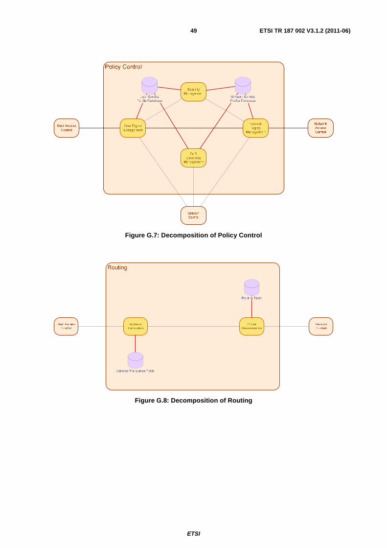
ETSI
ETSI TR 187 002 V3.1.2 (2011-06) 49
Policy Control
Network
Rights
Management
User Access
Control
Network
Access
Control
Session
Control
User Rights
Management
Security
Management
QoS
Capability
Management
User Service
Profile Database
Network Service
Profile Database
Figure G.7: Decomposition of Policy Control
Figure G.8: Decomposition of Routing
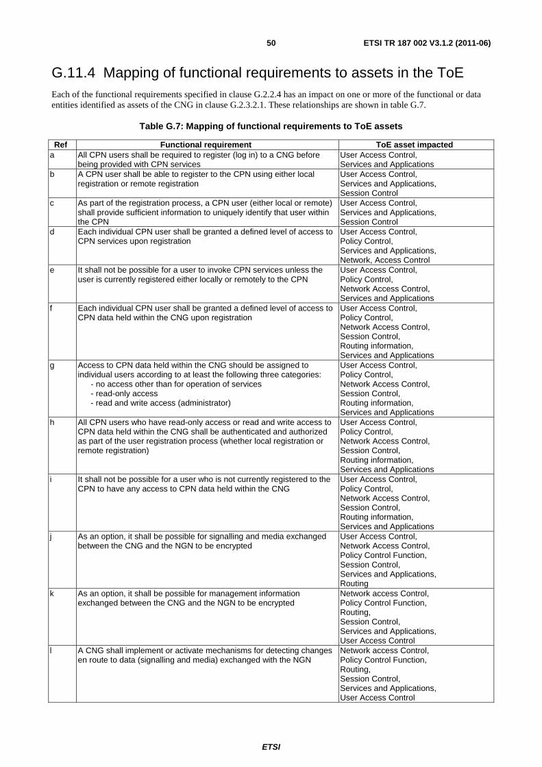
ETSI
ETSI TR 187 002 V3.1.2 (2011-06) 50
G.11.4 Mapping of functional requirements to assets in the ToE Each of the functional requirements specified in clause G.2.2.4 has an impact on one or more of the functional or data entities identified as assets of the CNG in clause G.2.3.2.1. These relationships are shown in table G.7.
Table G.7: Mapping of functional requirements to ToE assets
Ref Functional requirement ToE asset impacted a All CPN users shall be required to register (log in) to a CNG before
being provided with CPN services User Access Control, Services and Applications
b A CPN user shall be able to register to the CPN using either local registration or remote registration
User Access Control, Services and Applications, Session Control
c As part of the registration process, a CPN user (either local or remote) shall provide sufficient information to uniquely identify that user within the CPN
User Access Control, Services and Applications, Session Control
d Each individual CPN user shall be granted a defined level of access to CPN services upon registration
User Access Control, Policy Control, Services and Applications, Network, Access Control
e It shall not be possible for a user to invoke CPN services unless the user is currently registered either locally or remotely to the CPN
User Access Control, Policy Control, Network Access Control, Services and Applications
f Each individual CPN user shall be granted a defined level of access to CPN data held within the CNG upon registration
User Access Control, Policy Control, Network Access Control, Session Control, Routing information, Services and Applications
g Access to CPN data held within the CNG should be assigned to individual users according to at least the following three categories: - no access other than for operation of services - read-only access - read and write access (administrator)
User Access Control, Policy Control, Network Access Control, Session Control, Routing information, Services and Applications
h All CPN users who have read-only access or read and write access to CPN data held within the CNG shall be authenticated and authorized as part of the user registration process (whether local registration or remote registration)
User Access Control, Policy Control, Network Access Control, Session Control, Routing information, Services and Applications
i It shall not be possible for a user who is not currently registered to the CPN to have any access to CPN data held within the CNG
User Access Control, Policy Control, Network Access Control, Session Control, Routing information, Services and Applications
j As an option, it shall be possible for signalling and media exchanged between the CNG and the NGN to be encrypted
User Access Control, Network Access Control, Policy Control Function, Session Control, Services and Applications, Routing
k As an option, it shall be possible for management information exchanged between the CNG and the NGN to be encrypted
Network access Control, Policy Control Function, Routing, Session Control, Services and Applications, User Access Control
l A CNG shall implement or activate mechanisms for detecting changes en route to data (signalling and media) exchanged with the NGN
Network access Control, Policy Control Function, Routing, Session Control, Services and Applications, User Access Control
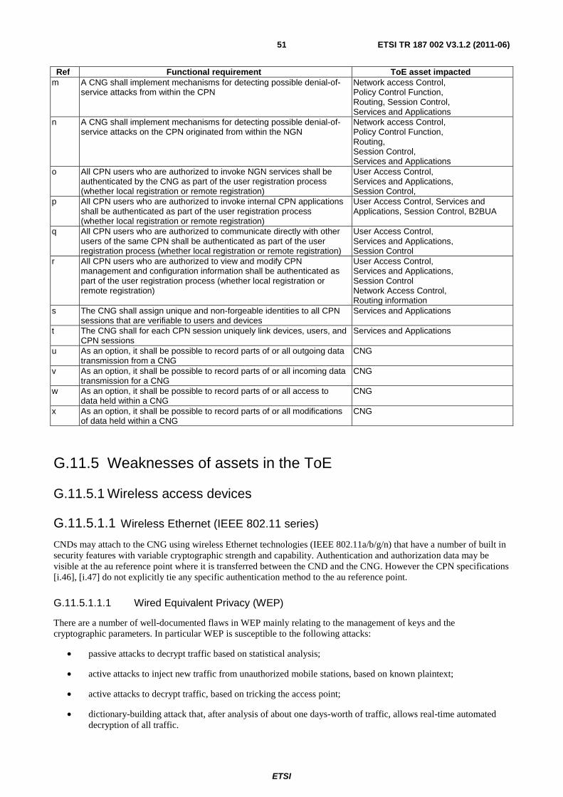
ETSI
ETSI TR 187 002 V3.1.2 (2011-06) 51
Ref Functional requirement ToE asset impacted m A CNG shall implement mechanisms for detecting possible denial-of-
service attacks from within the CPN Network access Control, Policy Control Function, Routing, Session Control, Services and Applications
n A CNG shall implement mechanisms for detecting possible denial-of-service attacks on the CPN originated from within the NGN
Network access Control, Policy Control Function, Routing, Session Control, Services and Applications
o All CPN users who are authorized to invoke NGN services shall be authenticated by the CNG as part of the user registration process (whether local registration or remote registration)
User Access Control, Services and Applications, Session Control,
p All CPN users who are authorized to invoke internal CPN applications shall be authenticated as part of the user registration process (whether local registration or remote registration)
User Access Control, Services and Applications, Session Control, B2BUA
q All CPN users who are authorized to communicate directly with other users of the same CPN shall be authenticated as part of the user registration process (whether local registration or remote registration)
User Access Control, Services and Applications, Session Control
r All CPN users who are authorized to view and modify CPN management and configuration information shall be authenticated as part of the user registration process (whether local registration or remote registration)
User Access Control, Services and Applications, Session Control Network Access Control, Routing information
s The CNG shall assign unique and non-forgeable identities to all CPN sessions that are verifiable to users and devices
Services and Applications
t The CNG shall for each CPN session uniquely link devices, users, and CPN sessions
Services and Applications
u As an option, it shall be possible to record parts of or all outgoing data transmission from a CNG
CNG
v As an option, it shall be possible to record parts of or all incoming data transmission for a CNG
CNG
w As an option, it shall be possible to record parts of or all access to data held within a CNG
CNG
x As an option, it shall be possible to record parts of or all modifications of data held within a CNG
CNG
G.11.5 Weaknesses of assets in the ToE
G.11.5.1 Wireless access devices
G.11.5.1.1 Wireless Ethernet (IEEE 802.11 series)
CNDs may attach to the CNG using wireless Ethernet technologies (IEEE 802.11a/b/g/n) that have a number of built in security features with variable cryptographic strength and capability. Authentication and authorization data may be visible at the au reference point where it is transferred between the CND and the CNG. However the CPN specifications [i.46], [i.47] do not explicitly tie any specific authentication method to the au reference point.
G.11.5.1.1.1 Wired Equivalent Privacy (WEP)
There are a number of well-documented flaws in WEP mainly relating to the management of keys and the cryptographic parameters. In particular WEP is susceptible to the following attacks:
• passive attacks to decrypt traffic based on statistical analysis;
• active attacks to inject new traffic from unauthorized mobile stations, based on known plaintext;
• active attacks to decrypt traffic, based on tricking the access point;
• dictionary-building attack that, after analysis of about one days-worth of traffic, allows real-time automated decryption of all traffic.
ETSI
ETSI TR 187 002 V3.1.2 (2011-06) 52
The cryptographic provision of confidentiality in WEP uses 64-bit and 128-bit key implementations of the RC4 algorithm but the use of repeated (re-used) initialisation vectors brings the effective key length down to 40 and 104 bits respectively. It is possible to recover the key within a few thousand transactions using known plaintext and signal injection, thus negating any security of the RC4 algorithm itself. An attack can be performed over the air in real-time with easily accessible tools.
WEP only provides confidentiality when used in WiFi applications and does not purport to offer any support of identification. Furthermore, WEP installations use a shared secret that may be susceptible to directory attacks.
G.11.5.1.1.1.1 Notes on RC4
RC4 is a two-stage key stream generator comprising a key scheduling algorithm (stage 1) and a random number generator (stage 2). RC4 was designed in 1987 to be very simple to implement and, whilst this goal is achieved, practical implementations (such as in WEP) often fail.
Perfect secrecy can be achieved using methods based upon the One Time Pad in which n bits of plain text are protected by an absolutely random key of length n to give a cipher text also of length n. However, RC4 uses a key that is shorter than the plain text length n and a pseudo-random number derived from an initialisation vector (seed) to generate a key stream sequence of length n. If the generator is good and the seed information is sufficiently long with respect to the key and changed for every instance of key stream generation, a key stream generator should approach the secrecy levels of the One Time Pad.
G.11.5.1.1.2 WiFi Protected Access (WPA)
In order to address the weaknesses in WEP, the WiFi Alliance proposed a revision to IEEE 802.11 [i.53], of which WPA implements a sub-set. WPA retains the use of RC4 as the encryption algorithm but improves on the key management sub-system by proposing the Temporal Key Integrity Protocol (TKIP) that uses inputs of the initialisation vector and the key to create a cryptographically modified key as input to RC4. TKIP also introduces an anti-replay counter as only the single hop anti-replay mechanisms are immune to store and forward errors and attacks.
WPA only provides confidentiality and does not purport to offer any support to identification. Furthermore, WPA installations use a shared secret that may be susceptible to directory attacks.
G.11.5.1.1.3 WPA-2 or Robust Security Network (RSN)
WPA-2 is a full implementation of 802.11 security and replaces RC4 with an algorithm derived from AES known as CCM (Counter Mode with Cipher Block Chaining Message Authentication Code).
WPA-2 provides confidentiality and integrity but does not purport to offer any support to identification. Furthermore, WPA-2 installations use a shared secret that may be susceptible to directory attacks although some modes provide rudimentary support for challenge-response authentication extensions that inhibit such attacks.
G.11.5.1.2 DECT devices
DECT has been specified in ETSI and contains built-in authentication and confidentiality countermeasures. There have been no successful attacks reported on the DECT Standard Authentication Algorithm (DSAA) or on the DECT Standard Cipher (DSC). However, the source of both these algorithms is private (i.e. not public in the way that AES is). Depending on manufacturer and specific devices the keys are shared between handsets and base stations and may be discoverable by an enterprising attacker although this probably requires physical access to the DECT base-station.
G.11.5.1.3 Bluetooth devices
There is significant historical evidence of the vulnerabilities in Bluetooth and on tools that can be used to exploit them (btscanner, btxml, Gnokki, OpenOBEX, Redfang and others). The number of Bluetooth attacks recorded is extensive and some are due to the extended physical range achievable on some Bluetooth devices (750m has been reported with unmodified equipment). Some well-known Bluetooth attacks are:
• Theft or alteration of personal information;
• Mobile phone IMEI number availability;
• Privacy, tracking;
ETSI
ETSI TR 187 002 V3.1.2 (2011-06) 53
• Complete control of certain devices;
• Denial of Service (DoS);
• Airborne viruses and worms.
Most attack tools are able to counter the conventional responses of placing the Bluetooth device in non-discoverable mode and of requiring the explicit pairing of devices. The Bluetooth specification does includes authentication of the devices and confidentiality protection of the radio interface transmissions although this is often based on default (published) PIN codes. Bluetooth specifies a 128-bit cryptographic confidentiality mechanism but the key is derived from the user-entered PIN code which are often only 4 digits (6 bits in BCD format) and that is often set to "0000" by default at installation and rarely changed.
G.11.5.2 SIP signalling
The vulnerabilities of SIP are well documented [i.52] and whilst many of these are resolvable, the core protocol still exhibits several weaknesses. In addition, because of the popularity and relative simplicity of SIP, there are a large number of attack tools available.
The CPN supports two variants of SIP each of which share attributes including extensibility:
• The Gm reference point supports IMS-SIP as defined in ES 283 003 [i.49].
• The Gm' reference point supports other variants of SIP as defined in RFC 3261 [i.18].
The concept of the CNG as a SIP B2BUA (i.e. acting as a SIP server to the CND and as a SIP client to the NGN) may require a mapping of IETF SIP to IMS SIP, or may allocate any non-IMS SIP signalling to the Ut reference point or directly to an uncontrolled SIP server across the root IP connection.
G.11.5.3 Lack of DoS Protection
SIP, IMS and the wireless connection security protection measures do not include any particular DoS protection capabilities. Generally, It is difficult to protect against even simple DoS attacks other than stack overflow. There are a number of automated DoS attack tools available and the likelihood of a DoS attack is high regardless of the protocol used.
Denial of Service attacks can be mounted by saturating a destination device with irrelevant, incorrect or malicious messages. As the protocol stack will attempt process all received messages as if valid, there is a significant danger that the device will have insufficient resources to process genuine messages. It is possible to add address filtering mechanisms, such as Firewalls, prior to the receiving entity to pre-process messages and block those that are received from source addresses that are black-listed or otherwise denied access.
G.11.5.4 Summary of ToE weaknesses
Table G.8 summarizes the weaknesses described in clauses G.2.5.1 to G.2.5.3. It also identifies potential unwanted incidents that may be the result of each weakness and specifies the knowledge required to successfully mount an attack.

ETSI
ETSI TR 187 002 V3.1.2 (2011-06) 54
Table G.8: Overview of Weaknesses
Weakness Unwanted Incidents Attack system knowledge
ID Name Description W-1 WEP protocol flaws WEP is susceptible to the
following attacks: • passive and active
decryption attacks; • active attacks to inject
new traffic; • dictionary-building
attacks.
Disclosure of sensitive information; Manipulation of private or other critical information (such as signalling); Masquerade
Public: Automated attack tools are available; attacks can be performed over the air in real-time.
W-2 WPA protocol flaws WPA installations use a shared secret that may be susceptible to directory attacks
Disclosure of sensitive information; Manipulation of private or other critical information (such as signalling); Masquerade
Public: There are known attacks and attack tools available.
W-3 WPA-2 protocol flaws WPA-2 installations use a shared secret that may be susceptible to directory attacks although some modes provide rudimentary support for challenge-response authentication extensions that inhibit such attacks.
Disclosure of sensitive information; Manipulation of private or other critical information (such as signalling); Masquerade
Restricted: Particular expertise is needed to carry out directory attacks against WPA-2. Critical: No attacks recorded against a WPA-2 implementation that includes directory attacks protection. An attacker would need to know very specific details of the particular implementation.
W-4 General SIP protocol weaknesses
The stateless architecture of SIP makes it possible for message flows to be disrupted by the receipt of spurious messages such as "BYE", "Invite", "Cancel" and "Refer"
Loss of service; Service instability; Masquerade
Public: There are a wide number of attack tools available.
W-5 No clear separation of CNG and NGN identities
The concept of the CNG as a SIP B2BUA (i.e. acting as a SIP server to the CND and as a SIP client to the NGN) may require a mapping of IETF SIP to IMS SIP, or may allocate any non-IMS SIP signalling to the Ut reference point or directly to an uncontrolled SIP server across the root IP connection.
Masquerade, Disclosure and manipulation of private or critical information
Public The general and well-known SIP attacks are applicable. In addition, depending on the implementation, information may also be accidentally leaked or changes due to B2BUA design flaws. In cases where an attacker gains access to B2BUA, any attack is in principle possible to launch both against the CNG and the NGN
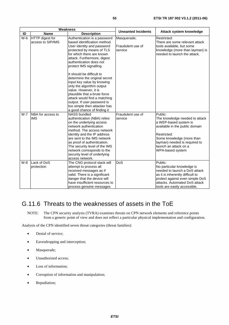
ETSI
ETSI TR 187 002 V3.1.2 (2011-06) 55
Weakness Unwanted Incidents Attack system knowledge
ID Name Description W-6 HTTP digest for
access to SIP/IMS Authentication is a password based identification method. User identity and password protected by means of TLS for which there are known attack. Furthermore, digest authentication does not protect IMS signalling. It should be difficult to determine the original secret input key value by knowing only the algorithm output value. However, it is plausible that a brute force attack would find a matching output. If user password is too simple then attacker has a good chance of finding it
Masquerade; Fraudulent use of service
Restricted: There are some relevant attack tools available, but some knowledge (more than layman) is needed to launch the attack.
W-7 NBA for access to IMS
NASS bundled authentication (NBA) relies on the underlying access network authentication method. The access network identity and the IP address are sent to the IMS network as proof of authentication. The security level of the IMS network corresponds to the security level of underlying access network.
Fraudulent use of service
Public: The knowledge needed to attack a WEP-based system is available in the public domain Restricted: Some knowledge (more than layman) needed is required to launch an attack on a WPA-based system
W-8 Lack of DoS protection
The CNG protocol stack will attempt to process all received messages as if valid. There is a significant danger that the device will have insufficient resources to process genuine messages
DoS Public: No particular knowledge is needed to launch a DoS attack as it is inherently difficult to protect against even simple DoS attacks. Automated DoS attack tools are easily accessible.
G.11.6 Threats to the weaknesses of assets in the ToE NOTE: The CPN security analysis (TVRA) examines threats on CPN network elements and reference points
from a generic point of view and does not reflect a particular physical implementation and configuration.
Analysis of the CPN identified seven threat categories (threat families):
• Denial of service;
• Eavesdropping and interception;
• Masquerade;
• Unauthorized access;
• Loss of information;
• Corruption of information and manipulation;
• Repudiation;
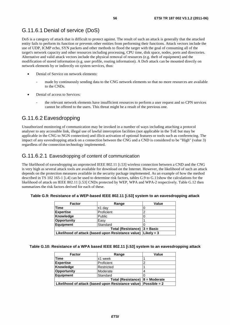
ETSI
ETSI TR 187 002 V3.1.2 (2011-06) 56
G.11.6.1 Denial of service (DoS)
DoS is a category of attack that is difficult to protect against. The result of such an attack is generally that the attacked entity fails to perform its function or prevents other entities from performing their functions. Attack vectors include the use of UDP, ICMP echo, SYN packets and other methods to flood the target with the goal of consuming all of the target's network capacity and other resources including processing, CPU time, disk space, nodes, ports and directories. Alternative and valid attack vectors include the physical removal of resources (e.g. theft of equipment) and the modification of stored information (e.g. user profile, routing information). A DoS attack can be mounted directly on network elements by or indirectly on system services, thus:
• Denial of Service on network elements:
- made by continuously sending data to the CNG network elements so that no more resources are available to the CNDs.
• Denial of access to Services:
- the relevant network elements have insufficient resources to perform a user request and so CPN services cannot be offered to the users. This threat might be a result of the previous one.
G.11.6.2 Eavesdropping
Unauthorized monitoring of communication may be invoked in a number of ways including attaching a protocol analyser to any accessible link, illegal use of lawful interception facilities (not applicable in the ToE but may be applicable in the CNG to NGN connection) and illicit activation of optional features or tools such as conferencing. The impact of any eavesdropping attack on a connection between the CNG and a CND is considered to be "High" (value 3) regardless of the connection technology implemented.
G.11.6.2.1 Eavesdropping of content of communication
The likelihood of eavesdropping an unprotected IEEE 802.11 [i.53] wireless connection between a CND and the CNG is very high as several attack tools are available for download on the Internet. However, the likelihood of such an attack depends on the protection measures available in the security package implemented. As an example of how the method described in TS 102 165-1 [i.4] can be used to determine risk factors, tables G.9 to G.11show the calculations for the likelihood of attack on IEEE 802.11 [i.53] CNDs protected by WEP, WPA and WPA-2 respectively. Table G.12 then summarizes the risk factors derived for each of these.
Table G.9: Resistance of a WEP-based IEEE 802.11 [i.53] system to an eavesdropping attack
Factor Range Value Time ≤1 day 0 Expertise Proficient 2 Knowledge Public 0 Opportunity Easy 1 Equipment Standard 0
Total (Resistance) 3 = Basic Likelihood of attack (based upon Resistance value) Likely = 3
Table G.10: Resistance of a WPA based IEEE 802.11 [i.53] system to an eavesdropping attack
Factor Range Value Time ≤1 week 1 Expertise Proficient 2 Knowledge Restricted 1 Opportunity Moderate 4 Equipment Standard 0
Total (Resistance) 8 = Moderate Likelihood of attack (based upon Resistance value) Possible = 2
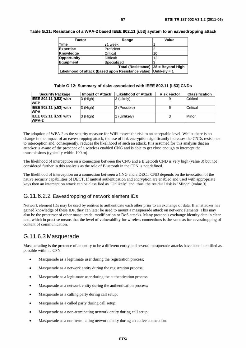
ETSI
ETSI TR 187 002 V3.1.2 (2011-06) 57
Table G.11: Resistance of a WPA-2 based IEEE 802.11 [i.53] system to an eavesdropping attack
Factor Range Value Time ≤1 week 1 Expertise Proficient 2 Knowledge Critical 10 Opportunity Difficult 12 Equipment Specialized 3
Total (Resistance) 28 = Beyond High Likelihood of attack (based upon Resistance value) Unlikely = 1
Table G.12: Summary of risks associated with IEEE 802.11 [i.53] CNDs
Security Package Impact of Attack Likelihood of Attack Risk Factor Classification IEEE 802.11 [i.53] with WEP
3 (High) 3 (Likely) 9 Critical
IEEE 802.11 [i.53] with WPA
3 (High) 2 (Possible) 6 Critical
IEEE 802.11 [i.53] with WPA-2
3 (High) 1 (Unlikely) 3 Minor
The adoption of WPA-2 as the security measure for WiFi moves the risk to an acceptable level. Whilst there is no change in the impact of an eavesdropping attack, the use of link encryption significantly increases the CNDs resistance to interception and, consequently, reduces the likelihood of such an attack. It is assumed for this analysis that an attacker is aware of the presence of a wireless enabled CNG and is able to get close enough to intercept the transmissions (typically within 100 m).
The likelihood of interception on a connection between the CNG and a Bluetooth CND is very high (value 3) but not considered further in this analysis as the role of Bluetooth in the CPN is not defined.
The likelihood of interception on a connection between a CNG and a DECT CND depends on the invocation of the native security capabilities of DECT. If mutual authentication and encryption are enabled and used with appropriate keys then an interception attack can be classified as "Unlikely" and, thus, the residual risk is "Minor" (value 3).
G.11.6.2.2 Eavesdropping of network element IDs
Network element IDs may be used by entities to authenticate each other prior to an exchange of data. If an attacker has gained knowledge of these IDs, they can later be used to mount a masquerade attack on network elements. This may also be the precursor of other masquerade, modification or DoS attacks. Many protocols exchange identity data in clear text, which in practise means that the level of vulnerability for wireless connections is the same as for eavesdropping of content of communication.
G.11.6.3 Masquerade
Masquerading is the pretence of an entity to be a different entity and several masquerade attacks have been identified as possible within a CPN:
• Masquerade as a legitimate user during the registration process;
• Masquerade as a network entity during the registration process;
• Masquerade as a legitimate user during the authentication process;
• Masquerade as a network entity during the authentication process;
• Masquerade as a calling party during call setup;
• Masquerade as a called party during call setup;
• Masquerade as a non-terminating network entity during call setup;
• Masquerade as a non-terminating network entity during an active connection.
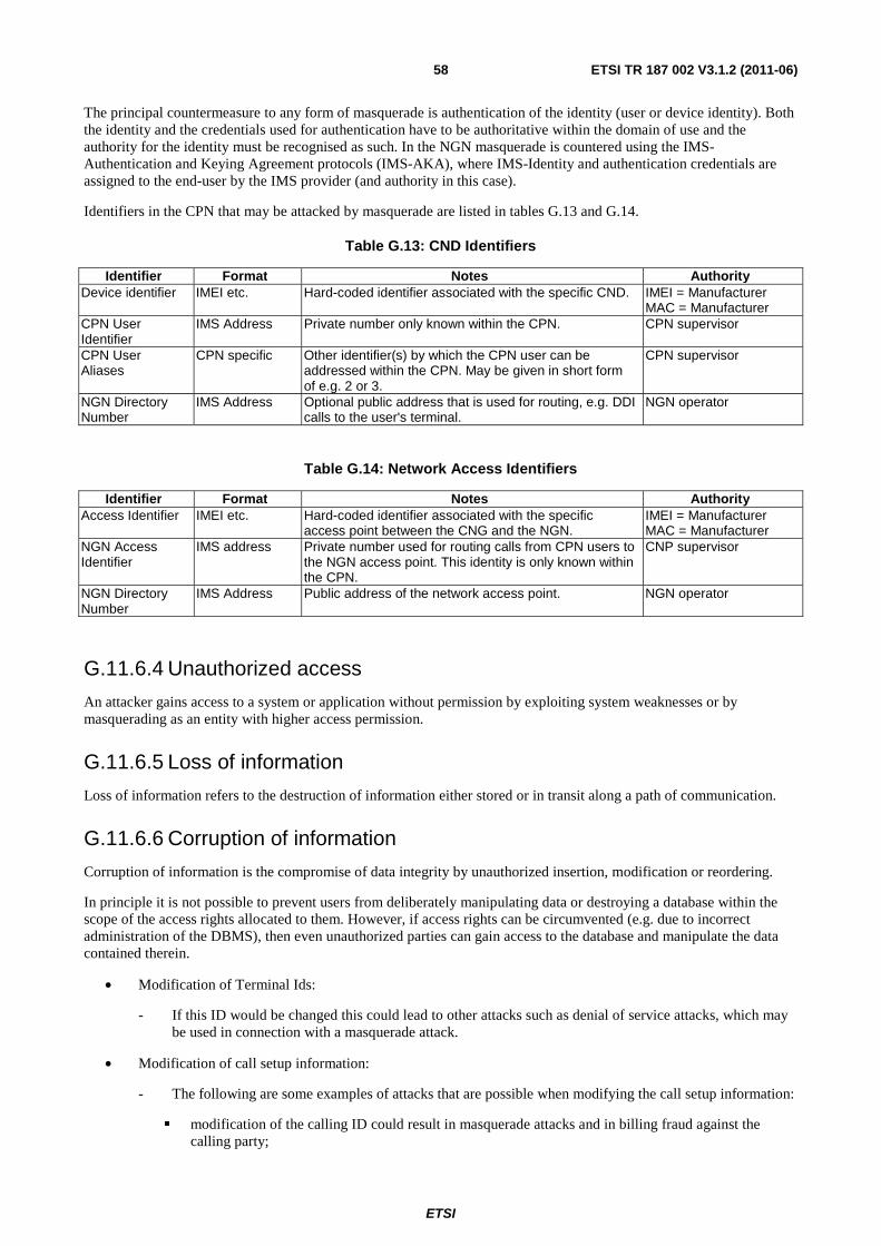
ETSI
ETSI TR 187 002 V3.1.2 (2011-06) 58
The principal countermeasure to any form of masquerade is authentication of the identity (user or device identity). Both the identity and the credentials used for authentication have to be authoritative within the domain of use and the authority for the identity must be recognised as such. In the NGN masquerade is countered using the IMS-Authentication and Keying Agreement protocols (IMS-AKA), where IMS-Identity and authentication credentials are assigned to the end-user by the IMS provider (and authority in this case).
Identifiers in the CPN that may be attacked by masquerade are listed in tables G.13 and G.14.
Table G.13: CND Identifiers
Identifier Format Notes Authority Device identifier IMEI etc. Hard-coded identifier associated with the specific CND. IMEI = Manufacturer
MAC = Manufacturer CPN User Identifier
IMS Address Private number only known within the CPN. CPN supervisor
CPN User Aliases
CPN specific Other identifier(s) by which the CPN user can be addressed within the CPN. May be given in short form of e.g. 2 or 3.
CPN supervisor
NGN Directory Number
IMS Address Optional public address that is used for routing, e.g. DDI calls to the user's terminal.
NGN operator
Table G.14: Network Access Identifiers
Identifier Format Notes Authority Access Identifier IMEI etc. Hard-coded identifier associated with the specific
access point between the CNG and the NGN. IMEI = Manufacturer MAC = Manufacturer
NGN Access Identifier
IMS address Private number used for routing calls from CPN users to the NGN access point. This identity is only known within the CPN.
CNP supervisor
NGN Directory Number
IMS Address Public address of the network access point. NGN operator
G.11.6.4 Unauthorized access
An attacker gains access to a system or application without permission by exploiting system weaknesses or by masquerading as an entity with higher access permission.
G.11.6.5 Loss of information
Loss of information refers to the destruction of information either stored or in transit along a path of communication.
G.11.6.6 Corruption of information
Corruption of information is the compromise of data integrity by unauthorized insertion, modification or reordering.
In principle it is not possible to prevent users from deliberately manipulating data or destroying a database within the scope of the access rights allocated to them. However, if access rights can be circumvented (e.g. due to incorrect administration of the DBMS), then even unauthorized parties can gain access to the database and manipulate the data contained therein.
• Modification of Terminal Ids:
- If this ID would be changed this could lead to other attacks such as denial of service attacks, which may be used in connection with a masquerade attack.
• Modification of call setup information:
- The following are some examples of attacks that are possible when modifying the call setup information:
� modification of the calling ID could result in masquerade attacks and in billing fraud against the calling party;
ETSI
ETSI TR 187 002 V3.1.2 (2011-06) 59
� modification of the called ID could result in denial of service attacks on the called party;
� modification of the service number might result in billing fraud against the NGN CSP (e.g. replacing a PRS number with a low rate number).
• Modification of routing information:
- Routing information has to be stored in each domain (e.g. either in the CNG or the NGN). Modification of this information may lead to denial of service attacks or to billing fraud against NGN CSPs as well as against legitimate CPN users.
• Modification of user access authentication data (e.g. for subsequent use):
- The service profile of each user stored in the CNG contains identification and authentication data. If this data is modified, it could lead to denial of service attacks on a legitimate CPN user attempting to access the environment of the CPN.
• Modification of data exchanged in the registration process:
- A user is required to register to the CPN before being able to make a call. Modifying registration data could lead to other threats such as denial of service, masquerade or fraud.
• Modification of content of communication:
- Not relevant for voice communication.
• Modification of network element Ids:
- Each network element must have a domain unique ID so that it can be identified in the CPN.
• Modification of service authentication data (i.e. part of content of communication):
- An ITSP may provide different kinds of services. For each subscriber of these services the service profile specifies which services the subscriber is allowed to use and the charging and billing information related to each service. A legitimate CPN user may find it attractive to change the entries in the service profile to enable use of special services that the user currently does not have access to or to change the charging rates for using the services.
G.11.6.7 Repudiation
Repudiation involves a user denying participation in a particular communication by one or more of the following:
• denial of transmission;
• denial of data receipt;
• denial of data access;
• denial of modification of data.
The level of risk presented by denial of involvement depends on a number of factors. If no audit records are maintained, the likelihood of plausible denial is increased but the impact depends on the value to the attacked party of the supposed infringement. Where log records are maintained the likelihood of plausible denial is reduced but again the impact to the attacked party depends on the value of the infringement. In cases where there is no financial element involved and where the parties in the CPN are mostly trusted, the implementation of legally assured non-repudiation countermeasures may not be necessary. It should be sufficient for a CPN network to maintain simple logs of both successful and failed access attempts and to make these available for expert interpretation to support analysis of other attacks.
G.11.6.8 Threat list
Tables G.15 to G.20 list the threats identified for the ToE, i.e. the CNG.
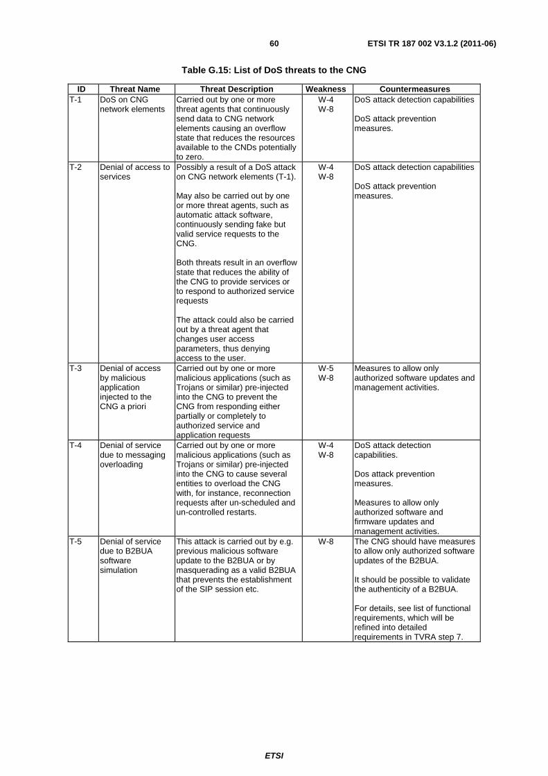
ETSI
ETSI TR 187 002 V3.1.2 (2011-06) 60
Table G.15: List of DoS threats to the CNG
ID Threat Name Threat Description Weakness Countermeasures T-1 DoS on CNG
network elements Carried out by one or more threat agents that continuously send data to CNG network elements causing an overflow state that reduces the resources available to the CNDs potentially to zero.
W-4 W-8
DoS attack detection capabilities DoS attack prevention measures.
T-2 Denial of access to services
Possibly a result of a DoS attack on CNG network elements (T-1). May also be carried out by one or more threat agents, such as automatic attack software, continuously sending fake but valid service requests to the CNG. Both threats result in an overflow state that reduces the ability of the CNG to provide services or to respond to authorized service requests The attack could also be carried out by a threat agent that changes user access parameters, thus denying access to the user.
W-4 W-8
DoS attack detection capabilities DoS attack prevention measures.
T-3 Denial of access by malicious application injected to the CNG a priori
Carried out by one or more malicious applications (such as Trojans or similar) pre-injected into the CNG to prevent the CNG from responding either partially or completely to authorized service and application requests
W-5 W-8
Measures to allow only authorized software updates and management activities.
T-4 Denial of service due to messaging overloading
Carried out by one or more malicious applications (such as Trojans or similar) pre-injected into the CNG to cause several entities to overload the CNG with, for instance, reconnection requests after un-scheduled and un-controlled restarts.
W-4 W-8
DoS attack detection capabilities. Dos attack prevention measures. Measures to allow only authorized software and firmware updates and management activities.
T-5 Denial of service due to B2BUA software simulation
This attack is carried out by e.g. previous malicious software update to the B2BUA or by masquerading as a valid B2BUA that prevents the establishment of the SIP session etc.
W-8 The CNG should have measures to allow only authorized software updates of the B2BUA. It should be possible to validate the authenticity of a B2BUA. For details, see list of functional requirements, which will be refined into detailed requirements in TVRA step 7.
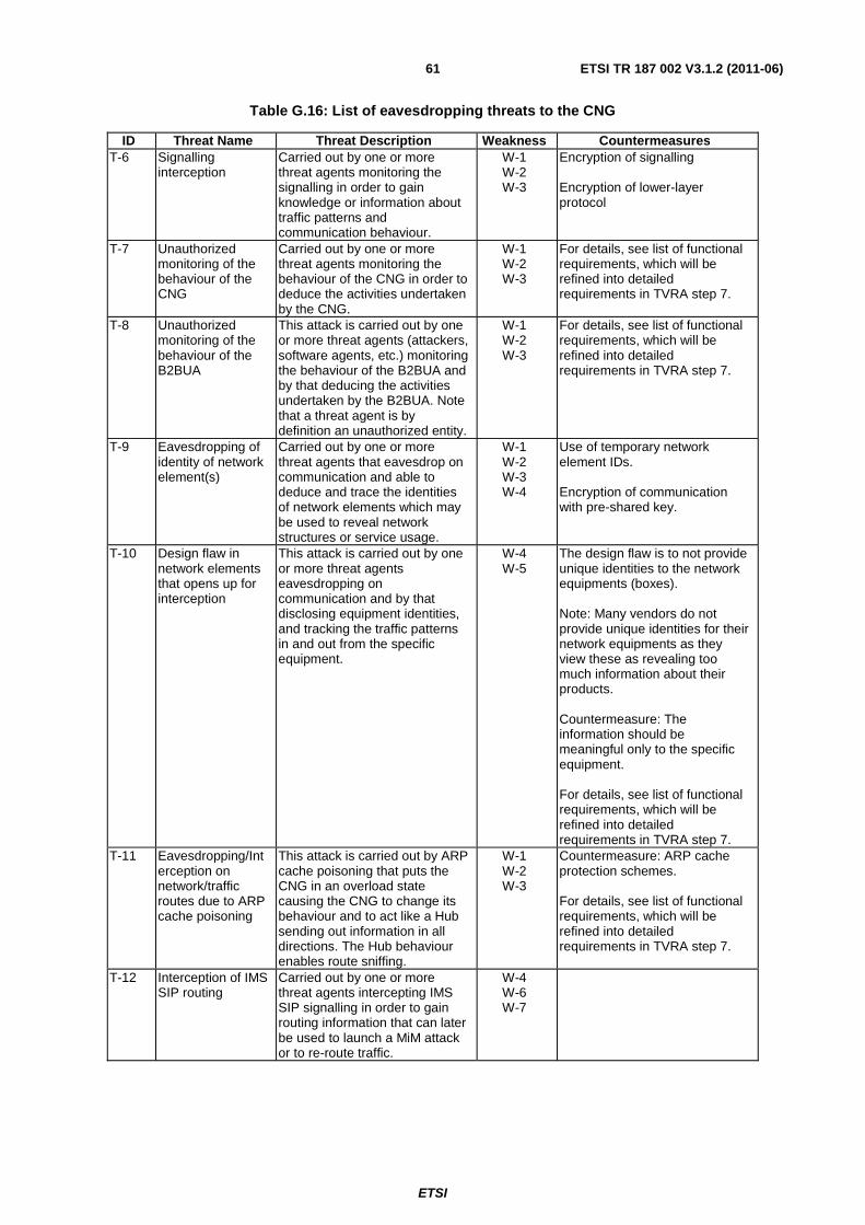
ETSI
ETSI TR 187 002 V3.1.2 (2011-06) 61
Table G.16: List of eavesdropping threats to the CNG
ID Threat Name Threat Description Weakness Countermeasures T-6 Signalling
interception Carried out by one or more threat agents monitoring the signalling in order to gain knowledge or information about traffic patterns and communication behaviour.
W-1 W-2 W-3
Encryption of signalling Encryption of lower-layer protocol
T-7 Unauthorized monitoring of the behaviour of the CNG
Carried out by one or more threat agents monitoring the behaviour of the CNG in order to deduce the activities undertaken by the CNG.
W-1 W-2 W-3
For details, see list of functional requirements, which will be refined into detailed requirements in TVRA step 7.
T-8 Unauthorized monitoring of the behaviour of the B2BUA
This attack is carried out by one or more threat agents (attackers, software agents, etc.) monitoring the behaviour of the B2BUA and by that deducing the activities undertaken by the B2BUA. Note that a threat agent is by definition an unauthorized entity.
W-1 W-2 W-3
For details, see list of functional requirements, which will be refined into detailed requirements in TVRA step 7.
T-9 Eavesdropping of identity of network element(s)
Carried out by one or more threat agents that eavesdrop on communication and able to deduce and trace the identities of network elements which may be used to reveal network structures or service usage.
W-1 W-2 W-3 W-4
Use of temporary network element IDs. Encryption of communication with pre-shared key.
T-10 Design flaw in network elements that opens up for interception
This attack is carried out by one or more threat agents eavesdropping on communication and by that disclosing equipment identities, and tracking the traffic patterns in and out from the specific equipment.
W-4 W-5
The design flaw is to not provide unique identities to the network equipments (boxes). Note: Many vendors do not provide unique identities for their network equipments as they view these as revealing too much information about their products. Countermeasure: The information should be meaningful only to the specific equipment. For details, see list of functional requirements, which will be refined into detailed requirements in TVRA step 7.
T-11 Eavesdropping/Interception on network/traffic routes due to ARP cache poisoning
This attack is carried out by ARP cache poisoning that puts the CNG in an overload state causing the CNG to change its behaviour and to act like a Hub sending out information in all directions. The Hub behaviour enables route sniffing.
W-1 W-2 W-3
Countermeasure: ARP cache protection schemes. For details, see list of functional requirements, which will be refined into detailed requirements in TVRA step 7.
T-12 Interception of IMS SIP routing
Carried out by one or more threat agents intercepting IMS SIP signalling in order to gain routing information that can later be used to launch a MiM attack or to re-route traffic.
W-4 W-6 W-7
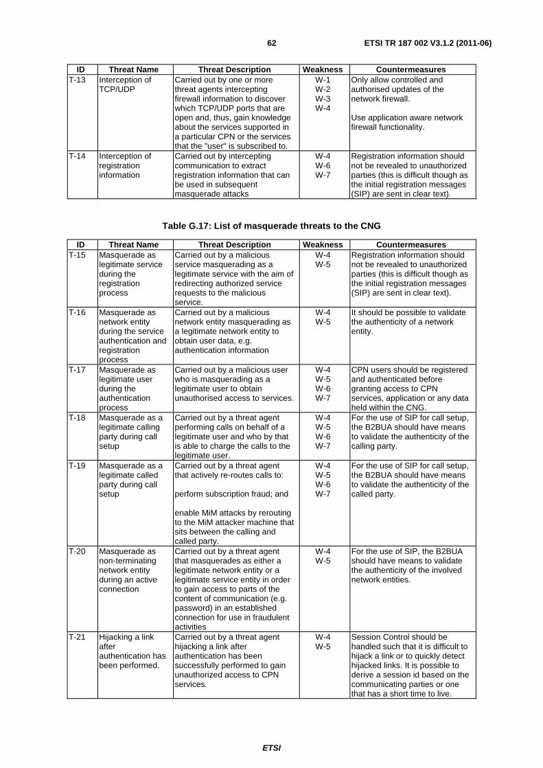
ETSI
ETSI TR 187 002 V3.1.2 (2011-06) 62
ID Threat Name Threat Description Weakness Countermeasures T-13 Interception of
TCP/UDP Carried out by one or more threat agents intercepting firewall information to discover which TCP/UDP ports that are open and, thus, gain knowledge about the services supported in a particular CPN or the services that the "user" is subscribed to.
W-1 W-2 W-3 W-4
Only allow controlled and authorised updates of the network firewall. Use application aware network firewall functionality.
T-14 Interception of registration information
Carried out by intercepting communication to extract registration information that can be used in subsequent masquerade attacks
W-4 W-6 W-7
Registration information should not be revealed to unauthorized parties (this is difficult though as the initial registration messages (SIP) are sent in clear text).
Table G.17: List of masquerade threats to the CNG
ID Threat Name Threat Description Weakness Countermeasures T-15 Masquerade as
legitimate service during the registration process
Carried out by a malicious service masquerading as a legitimate service with the aim of redirecting authorized service requests to the malicious service.
W-4 W-5
Registration information should not be revealed to unauthorized parties (this is difficult though as the initial registration messages (SIP) are sent in clear text).
T-16 Masquerade as network entity during the service authentication and registration process
Carried out by a malicious network entity masquerading as a legitimate network entity to obtain user data, e.g. authentication information
W-4 W-5
It should be possible to validate the authenticity of a network entity.
T-17 Masquerade as legitimate user during the authentication process
Carried out by a malicious user who is masquerading as a legitimate user to obtain unauthorised access to services.
W-4 W-5 W-6 W-7
CPN users should be registered and authenticated before granting access to CPN services, application or any data held within the CNG.
T-18 Masquerade as a legitimate calling party during call setup
Carried out by a threat agent performing calls on behalf of a legitimate user and who by that is able to charge the calls to the legitimate user.
W-4 W-5 W-6 W-7
For the use of SIP for call setup, the B2BUA should have means to validate the authenticity of the calling party.
T-19 Masquerade as a legitimate called party during call setup
Carried out by a threat agent that actively re-routes calls to: perform subscription fraud; and enable MiM attacks by rerouting to the MiM attacker machine that sits between the calling and called party.
W-4 W-5 W-6 W-7
For the use of SIP for call setup, the B2BUA should have means to validate the authenticity of the called party.
T-20 Masquerade as non-terminating network entity during an active connection
Carried out by a threat agent that masquerades as either a legitimate network entity or a legitimate service entity in order to gain access to parts of the content of communication (e.g. password) in an established connection for use in fraudulent activities
W-4 W-5
For the use of SIP, the B2BUA should have means to validate the authenticity of the involved network entities.
T-21 Hijacking a link after authentication has been performed.
Carried out by a threat agent hijacking a link after authentication has been successfully performed to gain unauthorized access to CPN services.
W-4 W-5
Session Control should be handled such that it is difficult to hijack a link or to quickly detect hijacked links. It is possible to derive a session id based on the communicating parties or one that has a short time to live.

ETSI
ETSI TR 187 002 V3.1.2 (2011-06) 63
Table G.18: List of unauthorized access threats to the CNG
ID Threat Name Threat Description Weakness Countermeasures T-22 Unauthorised
access to Management functions and elements
Carried out by a threat agent that modifies the routing tables to enable, for example, re-routing of traffic
W-4 W-5 W-6 W-7
Policy control and routing information held within the CNG should be protected from unauthorized modification.
T-23 Unauthorised access to network and/or services
Carried out by a threat agent that modifies information in the network elements, services or application to enable fraudulent use of CPN resources and services
W-4 W-5 W-6 W-7
Information held within the CNG, CNP services and applications should be protected from unauthorized modification.
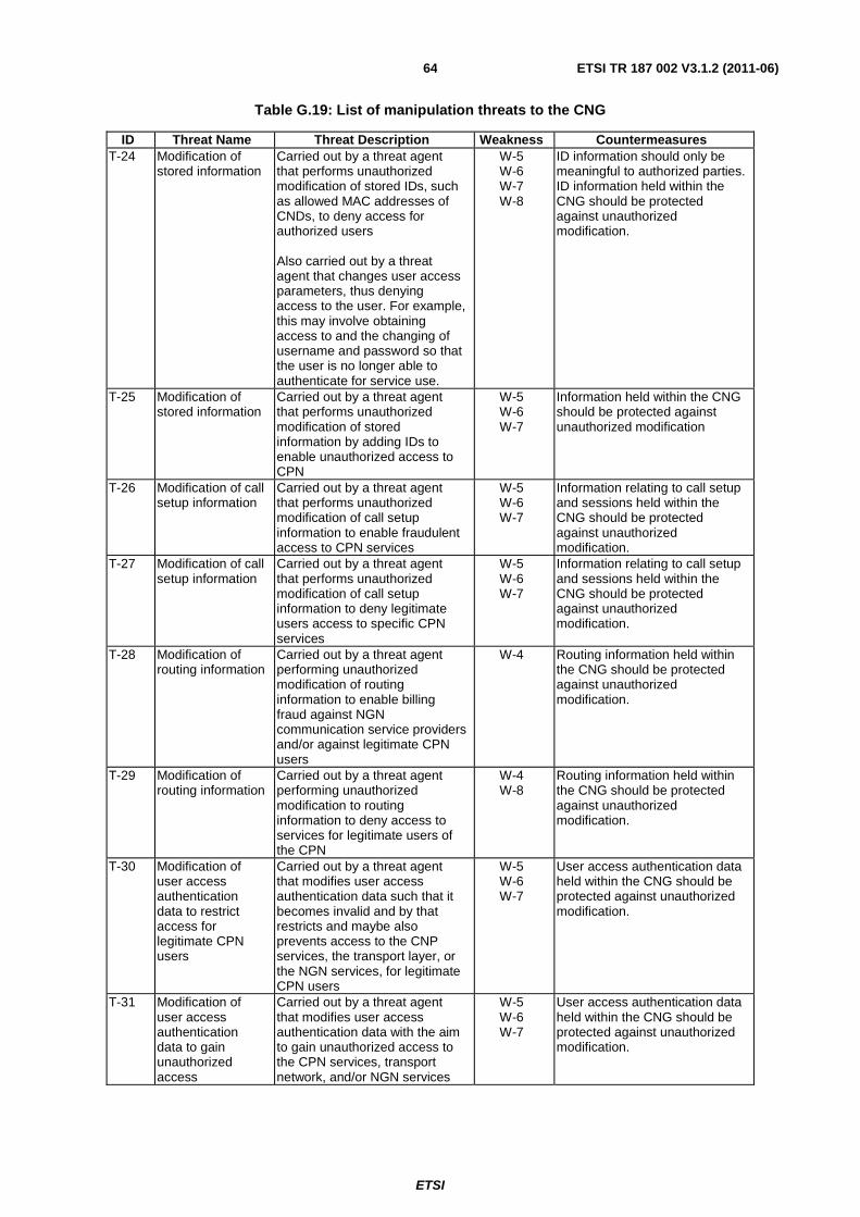
ETSI
ETSI TR 187 002 V3.1.2 (2011-06) 64
Table G.19: List of manipulation threats to the CNG
ID Threat Name Threat Description Weakness Countermeasures T-24 Modification of
stored information Carried out by a threat agent that performs unauthorized modification of stored IDs, such as allowed MAC addresses of CNDs, to deny access for authorized users Also carried out by a threat agent that changes user access parameters, thus denying access to the user. For example, this may involve obtaining access to and the changing of username and password so that the user is no longer able to authenticate for service use.
W-5 W-6 W-7 W-8
ID information should only be meaningful to authorized parties. ID information held within the CNG should be protected against unauthorized modification.
T-25 Modification of stored information
Carried out by a threat agent that performs unauthorized modification of stored information by adding IDs to enable unauthorized access to CPN
W-5 W-6 W-7
Information held within the CNG should be protected against unauthorized modification
T-26 Modification of call setup information
Carried out by a threat agent that performs unauthorized modification of call setup information to enable fraudulent access to CPN services
W-5 W-6 W-7
Information relating to call setup and sessions held within the CNG should be protected against unauthorized modification.
T-27 Modification of call setup information
Carried out by a threat agent that performs unauthorized modification of call setup information to deny legitimate users access to specific CPN services
W-5 W-6 W-7
Information relating to call setup and sessions held within the CNG should be protected against unauthorized modification.
T-28 Modification of routing information
Carried out by a threat agent performing unauthorized modification of routing information to enable billing fraud against NGN communication service providers and/or against legitimate CPN users
W-4 Routing information held within the CNG should be protected against unauthorized modification.
T-29 Modification of routing information
Carried out by a threat agent performing unauthorized modification to routing information to deny access to services for legitimate users of the CPN
W-4 W-8
Routing information held within the CNG should be protected against unauthorized modification.
T-30 Modification of user access authentication data to restrict access for legitimate CPN users
Carried out by a threat agent that modifies user access authentication data such that it becomes invalid and by that restricts and maybe also prevents access to the CNP services, the transport layer, or the NGN services, for legitimate CPN users
W-5 W-6 W-7
User access authentication data held within the CNG should be protected against unauthorized modification.
T-31 Modification of user access authentication data to gain unauthorized access
Carried out by a threat agent that modifies user access authentication data with the aim to gain unauthorized access to the CPN services, transport network, and/or NGN services
W-5 W-6 W-7
User access authentication data held within the CNG should be protected against unauthorized modification.
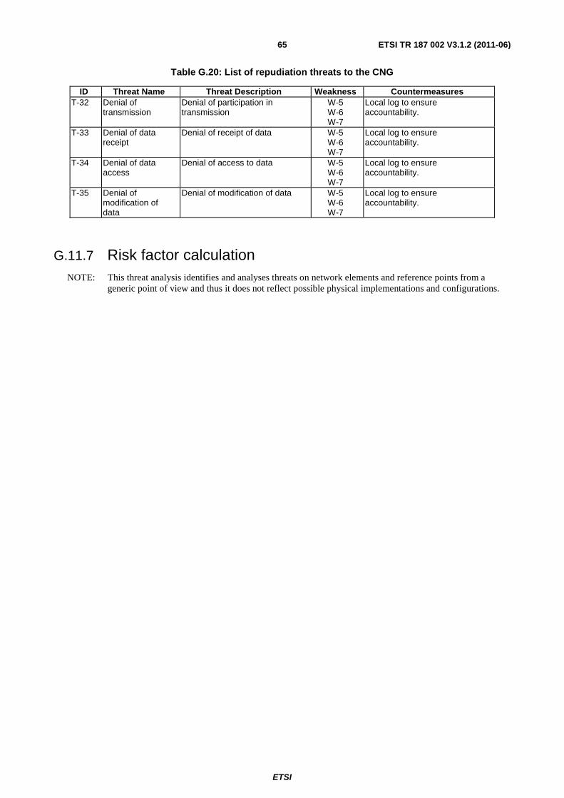
ETSI
ETSI TR 187 002 V3.1.2 (2011-06) 65
Table G.20: List of repudiation threats to the CNG
ID Threat Name Threat Description Weakness Countermeasures T-32 Denial of
transmission Denial of participation in transmission
W-5 W-6 W-7
Local log to ensure accountability.
T-33 Denial of data receipt
Denial of receipt of data W-5 W-6 W-7
Local log to ensure accountability.
T-34 Denial of data access
Denial of access to data W-5 W-6 W-7
Local log to ensure accountability.
T-35 Denial of modification of data
Denial of modification of data W-5 W-6 W-7
Local log to ensure accountability.
G.11.7 Risk factor calculation NOTE: This threat analysis identifies and analyses threats on network elements and reference points from a
generic point of view and thus it does not reflect possible physical implementations and configurations.

ETSI
ETSI TR 187 002 V3.1.2 (2011-06) 66
Table G.21: Risk factors for CPN ToE
Attack scenario Threats Motivation for attack Likelihood Impact Risk 1 Flooding the target for
Denial of Service T-1 T-2 T-4
Sabotage, Attacker satisfaction Likely (3) High (3) Critical (9)
2 Modifying stored information
T-2 T-3 T-5 T-24 T-30
Sabotage, Disabling and harming of individual subscribers, Attacker satisfaction
Unlikely (1) High (3) Minor (3)
3 Attaching a protocol analyser to any accessible link or other types of illegal monitoring of the CNG
T-6 T-7 T-8 T-9 T-11 T-12 T-13 T-14
Espionage, Getting information, Attacker satisfaction
Likely (3) High (3) Critical (9)
4 Design flaw or illegal activation of optional features/tools
T-10
Espionage, Getting information, Attacker satisfaction
Possible (2) High (3) Critical (6)
5 Hijacking a link after authentication has been performed. T-21
Fraud, Harming subscribers, Sabotage, Getting information, Attacker satisfaction
Possible (2) High (3) Critical (6)
6 Masquerade using authentication information, obtained by eavesdropping or similar
T-15 T-16 T-17 T-18 T-19 T-20
Fraud, Harming subscribers, Sabotage, Getting information, Attacker satisfaction
Possible (2) High (3) Critical (6)
7 Unauthorised access to data and services/applications T-22
T-23
Fraud, Harming providers, Sabotage, Getting information, Attacker satisfaction
Unlikely (1) High (3) Minor (3)
8 Modification of information T-24 T-25 T-26 T-27 T-28 T-29 T-30 T-31
Fraud, Harming providers, Sabotage, Getting information, Attacker satisfaction Possible (2) High (3) Critical (6)
9 Deletion of stored information T-27
T-29 T-30
Sabotage, Harming providers and individual subscribers, Fraud
Likely (3) High (3) Critical (9)
10 Deletion of data in transfer
T-27 T-29 T-30
Sabotage, Harming providers and individual subscribers, Fraud
Likely (3) High (3) Critical (9)
11 Modification of access rights of other parties
T-24 T-26 T-28 T-31
Harming providers and individual subscribers Possible (2) High (3) Critical (6)
12 Modification of stored information T-3
Sabotage, harming providers and individual subscribers
Possible (2) High (3) Critical (6)
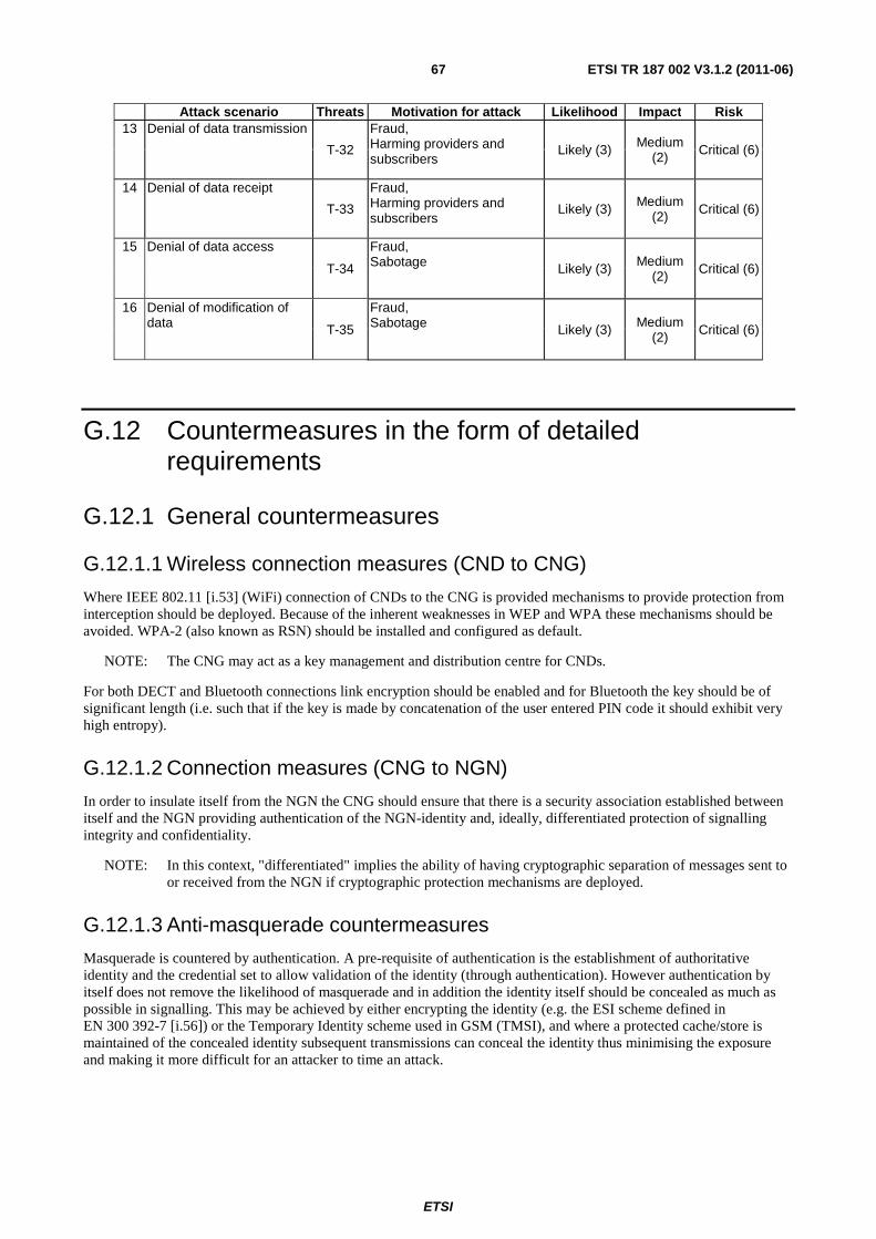
ETSI
ETSI TR 187 002 V3.1.2 (2011-06) 67
Attack scenario Threats Motivation for attack Likelihood Impact Risk 13 Denial of data transmission
T-32
Fraud, Harming providers and subscribers
Likely (3) Medium (2) Critical (6)
14 Denial of data receipt
T-33
Fraud, Harming providers and subscribers
Likely (3) Medium (2) Critical (6)
15 Denial of data access
T-34
Fraud, Sabotage Likely (3) Medium
(2) Critical (6)
16 Denial of modification of data T-35
Fraud, Sabotage Likely (3) Medium
(2) Critical (6)
G.12 Countermeasures in the form of detailed requirements
G.12.1 General countermeasures
G.12.1.1 Wireless connection measures (CND to CNG)
Where IEEE 802.11 [i.53] (WiFi) connection of CNDs to the CNG is provided mechanisms to provide protection from interception should be deployed. Because of the inherent weaknesses in WEP and WPA these mechanisms should be avoided. WPA-2 (also known as RSN) should be installed and configured as default.
NOTE: The CNG may act as a key management and distribution centre for CNDs.
For both DECT and Bluetooth connections link encryption should be enabled and for Bluetooth the key should be of significant length (i.e. such that if the key is made by concatenation of the user entered PIN code it should exhibit very high entropy).
G.12.1.2 Connection measures (CNG to NGN)
In order to insulate itself from the NGN the CNG should ensure that there is a security association established between itself and the NGN providing authentication of the NGN-identity and, ideally, differentiated protection of signalling integrity and confidentiality.
NOTE: In this context, "differentiated" implies the ability of having cryptographic separation of messages sent to or received from the NGN if cryptographic protection mechanisms are deployed.
G.12.1.3 Anti-masquerade countermeasures
Masquerade is countered by authentication. A pre-requisite of authentication is the establishment of authoritative identity and the credential set to allow validation of the identity (through authentication). However authentication by itself does not remove the likelihood of masquerade and in addition the identity itself should be concealed as much as possible in signalling. This may be achieved by either encrypting the identity (e.g. the ESI scheme defined in EN 300 392-7 [i.56]) or the Temporary Identity scheme used in GSM (TMSI), and where a protected cache/store is maintained of the concealed identity subsequent transmissions can conceal the identity thus minimising the exposure and making it more difficult for an attacker to time an attack.
ETSI
ETSI TR 187 002 V3.1.2 (2011-06) 68
Specific authentication countermeasures fall into one of (at least) 3 categories:
• Challenge response countermeasures
- The model used in DECT, TETRA, GSM and others in which a random challenge is offered and based on a shared secret a cryptographic response calculated. The strength of the measure lies in the inability of an attacker to correctly guess the response without the knowledge of the key.
• Signature countermeasure
- Applies to symmetric keying schemes whereby a document (data package) hash is signed by the private key of the claimant and verified as true by verifying the signed hash with the public key of the claimant. The strength of the measure relies on the inability of an attacker to find the private exponent of the key-pair.
• Message Authentication Code countermeasures
- Similar to the signature countermeasure but using symmetric keys to encrypt the hash of a document.
NOTE: Many pen-test environments allow MAC addresses to be masqueraded.
Table G.22 lists general countermeasures for the CNG and associate these to the earlier identified weaknesses. Clause G.3.2 lists the detailed security requirements to the CNG.
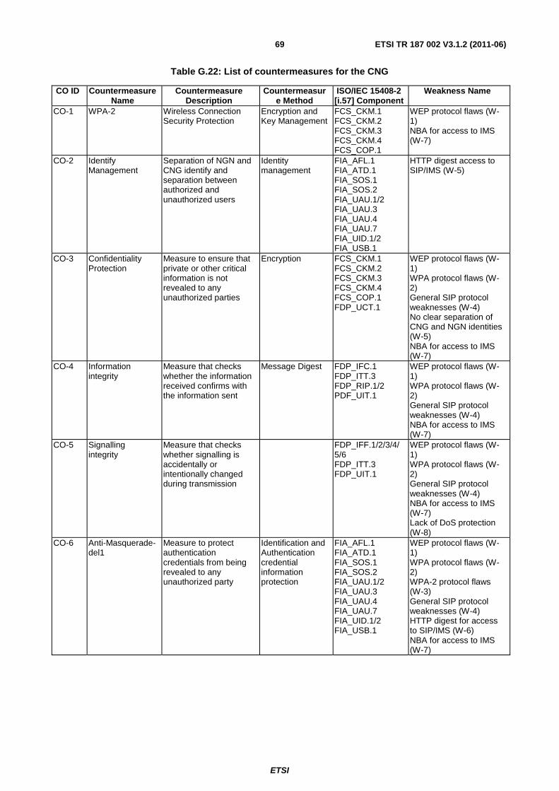
ETSI
ETSI TR 187 002 V3.1.2 (2011-06) 69
Table G.22: List of countermeasures for the CNG
CO ID Countermeasure Name
Countermeasure Description
Countermeasure Method
ISO/IEC 15408-2 [i.57] Component
Weakness Name
CO-1 WPA-2 Wireless Connection Security Protection
Encryption and Key Management
FCS_CKM.1 FCS_CKM.2 FCS_CKM.3 FCS_CKM.4 FCS_COP.1
WEP protocol flaws (W-1) NBA for access to IMS (W-7)
CO-2 Identify Management
Separation of NGN and CNG identify and separation between authorized and unauthorized users
Identity management
FIA_AFL.1 FIA_ATD.1 FIA_SOS.1 FIA_SOS.2 FIA_UAU.1/2 FIA_UAU.3 FIA_UAU.4 FIA_UAU.7 FIA_UID.1/2 FIA_USB.1
HTTP digest access to SIP/IMS (W-5)
CO-3 Confidentiality Protection
Measure to ensure that private or other critical information is not revealed to any unauthorized parties
Encryption FCS_CKM.1 FCS_CKM.2 FCS_CKM.3 FCS_CKM.4 FCS_COP.1 FDP_UCT.1
WEP protocol flaws (W-1) WPA protocol flaws (W-2) General SIP protocol weaknesses (W-4) No clear separation of CNG and NGN identities (W-5) NBA for access to IMS (W-7)
CO-4 Information integrity
Measure that checks whether the information received confirms with the information sent
Message Digest FDP_IFC.1 FDP_ITT.3 FDP_RIP.1/2 PDF_UIT.1
WEP protocol flaws (W-1) WPA protocol flaws (W-2) General SIP protocol weaknesses (W-4) NBA for access to IMS (W-7)
CO-5 Signalling integrity
Measure that checks whether signalling is accidentally or intentionally changed during transmission
FDP_IFF.1/2/3/4/5/6 FDP_ITT.3 FDP_UIT.1
WEP protocol flaws (W-1) WPA protocol flaws (W-2) General SIP protocol weaknesses (W-4) NBA for access to IMS (W-7) Lack of DoS protection (W-8)
CO-6 Anti-Masquerade-del1
Measure to protect authentication credentials from being revealed to any unauthorized party
Identification and Authentication credential information protection
FIA_AFL.1 FIA_ATD.1 FIA_SOS.1 FIA_SOS.2 FIA_UAU.1/2 FIA_UAU.3 FIA_UAU.4 FIA_UAU.7 FIA_UID.1/2 FIA_USB.1
WEP protocol flaws (W-1) WPA protocol flaws (W-2) WPA-2 protocol flaws (W-3) General SIP protocol weaknesses (W-4) HTTP digest for access to SIP/IMS (W-6) NBA for access to IMS (W-7)
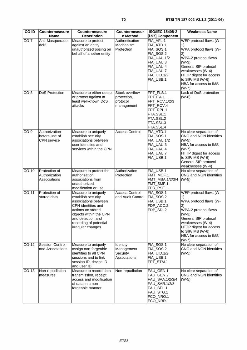
ETSI
ETSI TR 187 002 V3.1.2 (2011-06) 70
CO ID Countermeasure Name
Countermeasure Description
Countermeasure Method
ISO/IEC 15408-2 [i.57] Component
Weakness Name
CO-7 Anti-Masquerade-del2
Measure to protect against an entity unauthorized posing on behalf of another entity
Authentication Mechanism Protection
FIA_AFL.1 FIA_ATD.1 FIA_SOS.1 FIA_SOS.2 FIA_UAU.1/2 FIA_UAU.3 FIA_UAU.4 FIA_UAU.7 FIA_UID.1/2 FIA_USB.1
WEP protocol flaws (W-1) WPA protocol flaws (W-2) WPA-2 protocol flaws (W-3) General SIP protocol weaknesses (W-4) HTTP digest for access to SIP/IMS (W-6) NBA for access to IMS (W-7)
CO-8 DoS Protection Measure to either detect or protect against at least well-known DoS attacks
Stack overflow protection, protocol management
FPT_FLS.1 FPT.ITA.1 FPT_RCV.1/2/3 FPT_RCV.4 FPT_RPL.1 FTA.SSL.1 FTA.SSL.2 FTA.SSL.3 FTA.SSL.4
Lack of DoS protection (W-8)
CO-9 Authorization before use of CPN service
Measure to uniquely establish security associations between user identities and services within the CPN
Access Control FIA_ATD.1 FIA_SOS.1 FIA_UAU.1/2 FIA_UAU.3 FIA_UAU.4 FIA_UAU.7 FIA_USB.1
No clear separation of CNG and NGN identities (W-5) NBA for access to IMS (W-7) HTTP digest for access to SIP/IMS (W-6) General SIP protocol weaknesses (W-4)
CO-10 Protection of Authorization Associations
Measure to protect the authorization associations from unauthorized modification or use
Authorization Protection
FIA_USB.1 FMT_MOF.1 FMT_MSA.1/2/3/4 FMT_SMF.1 FPR_PSE.1
No clear separation of CNG and NGN identities (W-5)
CO-11 Protection of stored data
Measure to uniquely establish security associations between CPN identities and actions on stored objects within the CPN and detection and recording of potential irregular changes
Access Control and Audit Control
FIA_SOS.1 FIA_SOS.2 FIA_USB.1 FDP_ACC.2 FDP_SDI.2
WEP protocol flaws (W-1) WPA protocol flaws (W-2) WPA-2 protocol flaws (W-3) General SIP protocol weaknesses (W-4) HTTP digest for access to SIP/IMS (W-6) NBA for access to IMS (W-7)
CO-12 Session Control and Associations
Measure to uniquely assign non-forgeable identities to all CPN sessions and to link session ID, device ID and user ID
Identity Management Security Associations
FIA_SOS.1 FIA_SOS.2 FIA_UID.1/2 FIA_USB.1 FPT_STM.1
No clear separation of CNG and NGN identities (W-5)
CO-13 Non-repudiation measures
Measure to record data transmission, receipt, access and modification of data in a non-forgeable manner
Non-repudiation FAU_GEN.1 FAU_GEN.2 FAU_SAA.1/2/3/4 FAU_SAR.1/2/3 FAU_SEL.1 FAU_STG.1 FCO_NRO.1 FCO_NRR.1
No clear separation of CNG and NGN identities (W-5)
ETSI
ETSI TR 187 002 V3.1.2 (2011-06) 71
G.12.2 Detailed security requirements
G.12.2.1 Confidentiality requirements
• Internally to the CPN, a CNG transmitting private or other critical information (i.e. to a CND) shall protect the data from unauthorised disclosure.
• Internally to the CPN, a CNG receiving private or other critical information (i.e. from a CND) should verify that the data was protected from unauthorised disclosure.
• The CNG shall detect the end of the life of the key used for cryptographic protection of the wireless communication between the CND and the CNG.
G.12.2.2 Identification, authentication and authorization requirements
• A CPN-user attempting to invoke a CNG-mediated service shall be identified and authenticated by the CNG before being granted access to the service.
• The CNG shall implement an authentication failure handling policy.
• The CNG shall take action according to local authentication failure handling policy (which may include silently discarding the authentication and explicit failure notification, or in the case of a replay of credentials may include notification of the true owner of the credentials) upon detection of failure during identification, authentication and authorization.
• The CNG should detect replayed user and/or device credentials.
• When the CNG detects replayed user and/or device credentials, the CNG shall stop the relevant processes.
• The CNG shall implement a privacy protection policy specifying as a minimum private and critical information.
• When the CNG detects violation of the privacy protection policy the CNG shall discard all signalling, including signalling from the NGN.
• The CNG shall implement an authorization management handling policy.
• On reception at the CNG of a message to access configuration information for update and detection of authorization failure the CNG shall reject the request and manage the failure in accordance with the CPN authorization management handling policy.
• Where a CND invokes a session at the CNG the CNG shall record the association of session-id, invoking device identity and invoking user-id.
G.12.2.3 Integrity requirements
• On transmission of management information from the CNG to a CND the CNG shall append a timestamp or sequence number to the outgoing message.
• On reception at the CNG of a message containing management information the CNG shall extract the timestamp or sequence number and verify that the message has not been replayed.
• On reception at the CNG of a message to access or update configuration information the CNG shall allow access only if the sender is an administrator.
• On detection of a message integrity error at the CNG the CNG shall discard the message.
• On indication received at the CNG of a resource allocation expiry the CNG shall delete all residual data associated with the invocation of the resource.
ETSI
ETSI TR 187 002 V3.1.2 (2011-06) 72
G.12.2.4 Availability and DoS protection requirements
• On receipt of a valid (i.e. authorized) request for data stored in the CNG the CNG shall return the requested data to the requesting user.
• On receipt of a valid (i.e. authorized) request for access to a CNG hosted service or application the CNG shall provide the requested service or application to the requesting user.
• On detection of any system failure or discontinuity not specifically handled by other mechanisms the CNG shall revert to a known safe state.

ETSI
ETSI TR 187 002 V3.1.2 (2011-06) 73
Annex H: Identity and privacy protection TVRA for NGN-R3 Please refer to TS 187 016 [i.55].
ETSI
ETSI TR 187 002 V3.1.2 (2011-06) 74
Annex I: TVRA of NASS in NGN-R3
NOTE: Whilst the present document is a technical report it identifies requirements for future work as a direct consequence of the analysis and should not be interpreted as mandates in the scope of the present document. In all cases these requirements are considered indicative pending their ratification in formal ETSI Technical Specifications within the TISPAN Work Programme.
I.1 Scope of NASS TVRA The NASS TVRA is based on the stage 2 definitions of NASS from ES 282 004 [i.5] and the stage 3 specifications referred to in ES 282 004 [i.5]. In cases where other stage 3 specifications have been examined as part of the analysis they are explicitly cited in the present document.
The NASS TVRA identifies the exposed interfaces between NASS and the NGN and NASS and the UE, and describes how these can be exploited as attack interfaces.
The purpose of the NASS TVRA is to identify whether the NASS specifications fulfil the security requirements as defined in TS 187 001 [i.6] and to identify gaps, if there are any, between the NASS stage 2 and stage 3 specifications and the NGN security requirements as specified in TS 187 001 [i.6] and the NGN security architecture as specified in TS 187 003 [i.7]. The analysis also identifies potential security problems arising from the NASS stage 2 and stage 3 specifications.
I.2 NASS TVRA Target of Evaluation (ToE) This clause defines the Target of Evaluation (ToE) for the NASS TVRA, the ToE environment, the internal interfaces (internal to the target) and the external interfaces (interfaces between the ToE and the ToE environment).
I.2.1 Definitions ES 282 004 [i.5] provides a number of definitions that are essential to the understanding of the ToE description.
authentication: property by which the correct identity of an entity or party is established with a required assurance
NOTE: The party being authenticated could be a user, subscriber, home environment or serving network (see TR 121 905 [i.58]).
authorization: granting of permission based on authenticated identification (see ISO/IEC 7498-2 [i.59])
NOTE: In some contexts, authorization may be granted without requiring authentication or identification e.g. emergency call services.
Customer Network Gateway (CNG): gateway between the Customer Premises Network (CPN) and the Access Network
NOTE: A Customer Network Gateway may be in its simplest form a bridged or routed modem, and in a more advanced form be an IAD.
explicit authentication: authentication that requires that the party to be authenticated performs an authentication procedure (to verify the claimed identity of the party)
NOTE: For example, in IMS security (TS 133 203 [i.19]), explicit authentication is provided with full AKA directed towards the IMS client entity (represented by IMPI/IMPU and USIM/ISIM) and also implicit authentication is provided by means of the IPsec security associations.
implicit authentication: authentication based on a trusted relationship already established between two parties, or based on one or more outputs of an authentication procedure already established between two parties
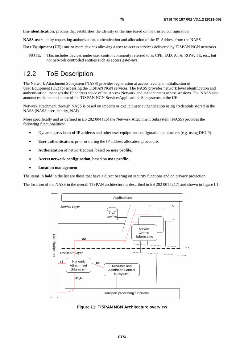
ETSI
ETSI TR 187 002 V3.1.2 (2011-06) 75
line identification: process that establishes the identity of the line based on the trusted configuration
NASS user: entity requesting authorization, authentication and allocation of the IP-Address from the NASS
User Equipment (UE): one or more devices allowing a user to access services delivered by TISPAN NGN networks
NOTE: This includes devices under user control commonly referred to as CPE, IAD, ATA, RGW, TE, etc., but not network controlled entities such as access gateways.
I.2.2 ToE Description The Network Attachment Subsystem (NASS) provides registration at access level and initialisation of User Equipment (UE) for accessing the TISPAN NGN services. The NASS provides network level identification and authentication, manages the IP address space of the Access Network and authenticates access sessions. The NASS also announces the contact point of the TISPAN NGN Service/Applications Subsystems to the UE.
Network attachment through NASS is based on implicit or explicit user authentication using credentials stored in the NASS (NASS user identity, NAI).
More specifically and as defined in ES 282 004 [i.5] the Network Attachment Subsystem (NASS) provides the following functionalities:
• Dynamic provision of IP address and other user equipment configuration parameters (e.g. using DHCP).
• User authentication, prior or during the IP address allocation procedure.
• Authorization of network access, based on user profile.
• Access network configuration, based on user profile.
• Location management.
The items in bold in the list are those that have a direct bearing on security functions and on privacy protection.
The location of the NASS in the overall TISPAN architecture is described in ES 282 001 [i.17] and shown in figure I.1.
….
…
ServiceControl
Subsystems
User Equ
ipment
Service Layer
Transport processing funct ions
Resource and Admission Control
Subsystem
Applicat ions
Userprofiles
a1,a3
Transport Layer
e4
e2
e3 Network Attachment Subsystem
Figure I.1: TISPAN NGN Architecture overview
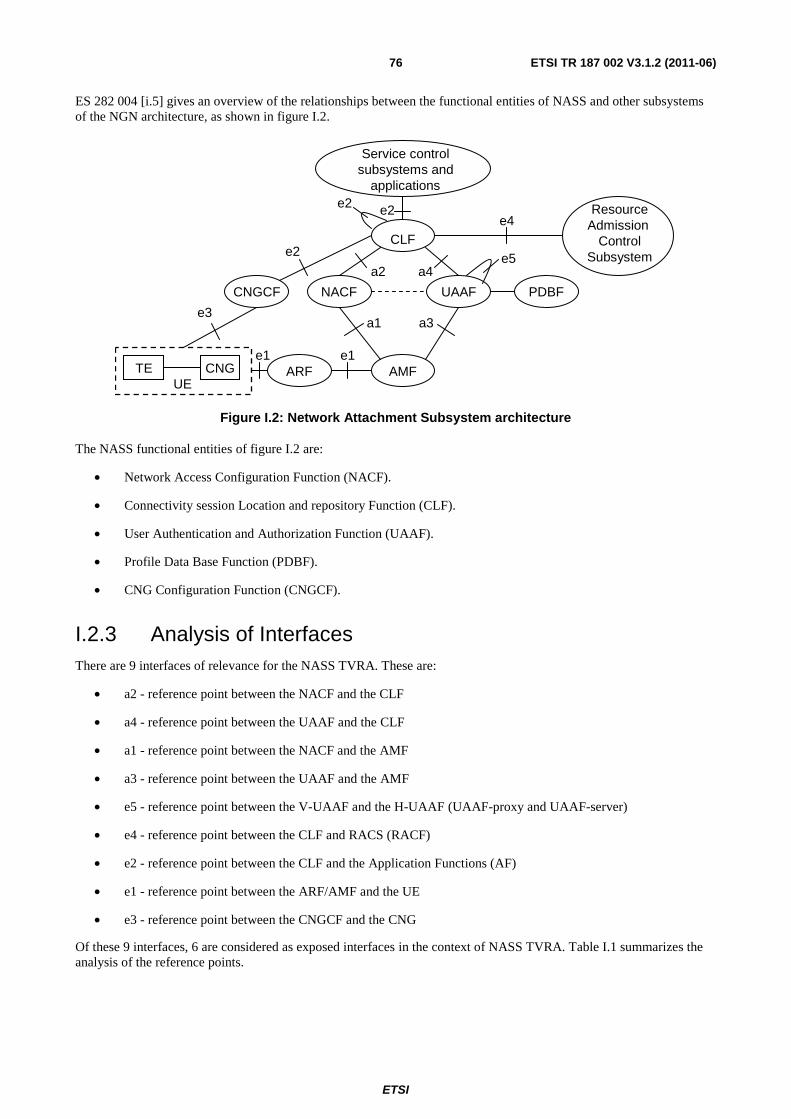
ETSI
ETSI TR 187 002 V3.1.2 (2011-06) 76
ES 282 004 [i.5] gives an overview of the relationships between the functional entities of NASS and other subsystems of the NGN architecture, as shown in figure I.2.
UETE CNG ARF AMF
CNGCF NACF UAAF PDBF
CLF
Service controlsubsystems and
applications
ResourceAdmission
ControlSubsystem
e3
e1 e1
a1 a3
a2 a4
e4e2e2
e2 e5
Figure I.2: Network Attachment Subsystem architecture
The NASS functional entities of figure I.2 are:
• Network Access Configuration Function (NACF).
• Connectivity session Location and repository Function (CLF).
• User Authentication and Authorization Function (UAAF).
• Profile Data Base Function (PDBF).
• CNG Configuration Function (CNGCF).
I.2.3 Analysis of Interfaces There are 9 interfaces of relevance for the NASS TVRA. These are:
• a2 - reference point between the NACF and the CLF
• a4 - reference point between the UAAF and the CLF
• a1 - reference point between the NACF and the AMF
• a3 - reference point between the UAAF and the AMF
• e5 - reference point between the V-UAAF and the H-UAAF (UAAF-proxy and UAAF-server)
• e4 - reference point between the CLF and RACS (RACF)
• e2 - reference point between the CLF and the Application Functions (AF)
• e1 - reference point between the ARF/AMF and the UE
• e3 - reference point between the CNGCF and the CNG
Of these 9 interfaces, 6 are considered as exposed interfaces in the context of NASS TVRA. Table I.1 summarizes the analysis of the reference points.
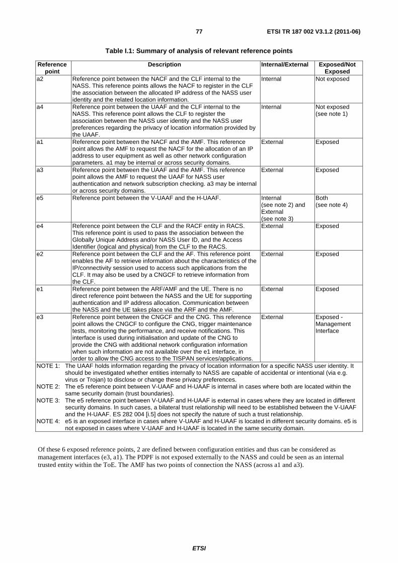
ETSI
ETSI TR 187 002 V3.1.2 (2011-06) 77
Table I.1: Summary of analysis of relevant reference points
Reference point
Description Internal/External Exposed/Not Exposed
a2 Reference point between the NACF and the CLF internal to the NASS. This reference points allows the NACF to register in the CLF the association between the allocated IP address of the NASS user identity and the related location information.
Internal Not exposed
a4 Reference point between the UAAF and the CLF internal to the NASS. This reference point allows the CLF to register the association between the NASS user identity and the NASS user preferences regarding the privacy of location information provided by the UAAF.
Internal Not exposed (see note 1)
a1 Reference point between the NACF and the AMF. This reference point allows the AMF to request the NACF for the allocation of an IP address to user equipment as well as other network configuration parameters. a1 may be internal or across security domains.
External Exposed
a3 Reference point between the UAAF and the AMF. This reference point allows the AMF to request the UAAF for NASS user authentication and network subscription checking. a3 may be internal or across security domains.
External Exposed
e5 Reference point between the V-UAAF and the H-UAAF. Internal (see note 2) and External (see note 3)
Both (see note 4)
e4 Reference point between the CLF and the RACF entity in RACS. This reference point is used to pass the association between the Globally Unique Address and/or NASS User ID, and the Access Identifier (logical and physical) from the CLF to the RACS.
External Exposed
e2 Reference point between the CLF and the AF. This reference point enables the AF to retrieve information about the characteristics of the IP/connectivity session used to access such applications from the CLF. It may also be used by a CNGCF to retrieve information from the CLF.
External Exposed
e1 Reference point between the ARF/AMF and the UE. There is no direct reference point between the NASS and the UE for supporting authentication and IP address allocation. Communication between the NASS and the UE takes place via the ARF and the AMF.
External Exposed
e3 Reference point between the CNGCF and the CNG. This reference point allows the CNGCF to configure the CNG, trigger maintenance tests, monitoring the performance, and receive notifications. This interface is used during initialisation and update of the CNG to provide the CNG with additional network configuration information when such information are not available over the e1 interface, in order to allow the CNG access to the TISPAN services/applications.
External Exposed - Management Interface
NOTE 1: The UAAF holds information regarding the privacy of location information for a specific NASS user identity. It should be investigated whether entities internally to NASS are capable of accidental or intentional (via e.g. virus or Trojan) to disclose or change these privacy preferences.
NOTE 2: The e5 reference point between V-UAAF and H-UAAF is internal in cases where both are located within the same security domain (trust boundaries).
NOTE 3: The e5 reference point between V-UAAF and H-UAAF is external in cases where they are located in different security domains. In such cases, a bilateral trust relationship will need to be established between the V-UAAF and the H-UAAF. ES 282 004 [i.5] does not specify the nature of such a trust relationship.
NOTE 4: e5 is an exposed interface in cases where V-UAAF and H-UAAF is located in different security domains. e5 is not exposed in cases where V-UAAF and H-UAAF is located in the same security domain.
Of these 6 exposed reference points, 2 are defined between configuration entities and thus can be considered as management interfaces (e3, a1). The PDPF is not exposed externally to the NASS and could be seen as an internal trusted entity within the ToE. The AMF has two points of connection the NASS (across a1 and a3).
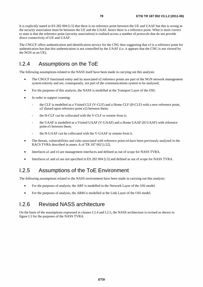
ETSI
ETSI TR 187 002 V3.1.2 (2011-06) 78
It is explicitly stated in ES 282 004 [i.5] that there is no reference point between the UE and UAAF but this is wrong as the security association must be between the UE and the UAAF, hence there is a reference point. What is more correct to state is that the reference point (security association) is realised across a number of protocols that do not provide direct connectivity of UE and UAAF.
The CNGCF offers authentication and identification service for the CNG thus suggesting that e3 is a reference point for authentication but that this authentication is not controlled by the UAAF (i.e. it appears that the CNG is not viewed by the NGN as an UE).
I.2.4 Assumptions on the ToE The following assumptions related to the NASS itself have been made in carrying out this analysis:
• The CNGCF functional entity and its associated e2 reference points are part of the NGN network management system entirely and are, consequently, not part of the communications system to be analysed;
• For the purposes of this analysis, the NASS is modelled at the Transport Layer of the OSI;
• In order to support roaming:
- the CLF is modelled as a Visited CLF (V-CLF) and a Home CLF (H-CLF) with a new reference point, e2' (based upon reference point e2) between them;
- the H-CLF can be collocated with the V-CLF or remote from it;
- the UAAF is modelled as a Visited UAAF (V-UAAF) and a Home UAAF (H-UAAF) with reference point e5 between them;
- the H-UAAF can be collocated with the V-UAAF or remote from it.
• The threats, vulnerabilities and risks associated with reference point e4 have been previously analysed in the RACS TVRA described in annex A of TR 187 002 [i.52].
• Interfaces a1 and e3 are management interfaces and defined as out of scope for NASS TVRA.
• Interfaces a1 and a3 are not specified in ES 282 004 [i.5] and defined as out of scope for NASS TVRA.
I.2.5 Assumptions of the ToE Environment The following assumptions related to the NASS environment have been made in carrying out this analysis:
• For the purposes of analysis, the ARF is modelled in the Network Layer of the OSI model.
• For the purposes of analysis, the ARM is modelled at the Link Layer of the OSI model.
I.2.6 Revised NASS architecture On the basis of the assumptions expressed in clauses I.2.4 and I.2.5, the NASS architecture is revised as shown in figure I.3 for the purposes of the NASS TVRA.
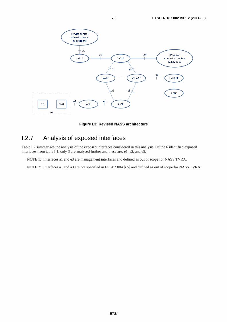
ETSI
ETSI TR 187 002 V3.1.2 (2011-06) 79
Service control
subsystems and
applications
Resource
Admission Control
Subsystem
V-CLFH-CLF
NACF V-UAAF H-UAAF
PDBF
AMFARFCNGTE
UE
e2
e2’ e4
e5
a2
a3
a4
a1
e1 e1
Figure I.3: Revised NASS architecture
I.2.7 Analysis of exposed interfaces Table I.2 summarizes the analysis of the exposed interfaces considered in this analysis. Of the 6 identified exposed interfaces from table I.1, only 3 are analysed further and these are: e1, e2, and e5.
NOTE 1: Interfaces a1 and e3 are management interfaces and defined as out of scope for NASS TVRA.
NOTE 2: Interfaces a1 and a3 are not specified in ES 282 004 [i.5] and defined as out of scope for NASS TVRA.
ETSI
ETSI TR 187 002 V3.1.2 (2011-06) 80
Table I.2: Summary of analysis of exposed reference points
No. Scenario description Exposed reference
points
Protocol Exposed assets
1 V-UAAF and H-UAAF across security domains.
e5 DIAMETER or RADIUS
NASS User ID, Privacy Indicator, Globally Unique Address, QoS Profile Information (optional), and Initial Gate Setting (List of allowed destinations, list of denied destinations and default bandwidth).
2 Information Query Request between AF and CLF
e2 DIAMETER Globally Unique IP Address, NASS User ID, and AF Identity
3 Information Query Response between CLF and AF
e2 DIAMETER NASS User ID, Location Information (optional), RACS contact point (optional), Terminal Type (optional), Access Network Type (optional), Physical Access ID (optional), and Logical Access ID (optional)
4 Event Registration Request between AF and CLF
e2 DIAMETER Subscription Duration, NASS User ID (optional), Event, Globally Unique IP Address (optional), and AD Identity (optional)
5 Event Registration Response between CLF and AF
e2 DIAMETER Update Action, NASS User UD, Event, and Globally Unique Address
6 Notification Event Request between CLF and AF
e2 DIAMETER Globally Unique Address, NASS User ID, and Event
7 Notification Event Response between AF and CLF
e2 DIAMETER Globally Unique Address, NASS User ID, Event, and Result
8 Network Access Authentication between UE and NASS (via ARF)
e2 DIAMETER NASS User Credentials (password, token, certificate, etc.)
9 IP Address Allocation and distribution of other network configuration parameters between UE and NASS (via ARF)
e2 DIAMETER NASS User Credentials (password, token, certificate, etc.)
10 Implicit line authentication using ARF/AMF as proxies
e1 The protocol used for IP address allocation
Subscriber line ID, NASS-Port-ID, NASS-Port or Calling-Station-ID (line identification information)
11 Explicit authentication using ARF/AMF as proxies
e1 PPP/CHAP, EAP/CHAP, EAPoL, PANA, RADIUS
NASS user credentials (SIM, password, token, certificate, etc.), NAI
12 IP address allocation to UE using ARF/AMF as proxies
e1 RADIUS/Diameter DHCP or PPP request (location, UE configurations)
NOTE 3: The analysis of e2 relevant scenarios also holds for e2' scenarios.
I.3 NASS security objectives 1) NASS should enable users to register securely to the NGN at the access level
2) NASS should provide registered users with secure access to the NGN and its services
3) NASS should securely allocate and manage IP addresses within the NGN access network
4) NASS should enable a user terminal to be moved securely from one access point to another even if the access points are in different networks
NOTE 1: NASS registration involves the identification, authentication, and authorization procedures between the UE and the NASS to control the access to the NASS.
NOTE 2: Two authentication types are defined for NASS: Implicit authentication and explicit authentication.
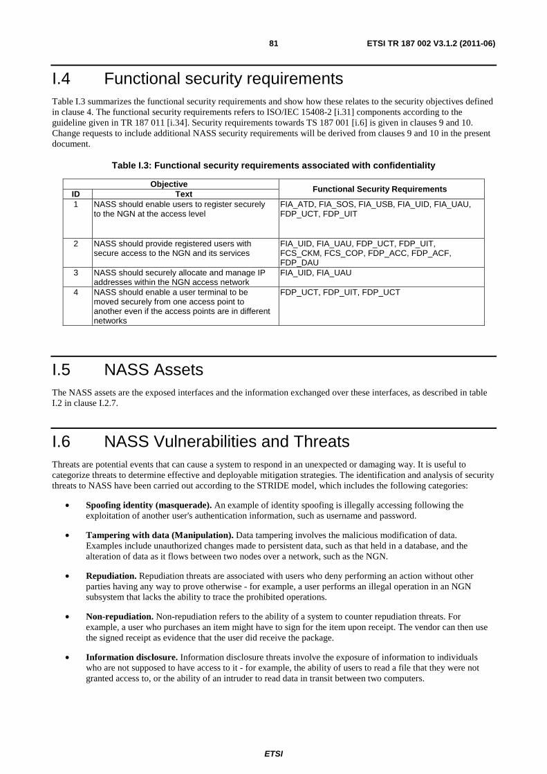
ETSI
ETSI TR 187 002 V3.1.2 (2011-06) 81
I.4 Functional security requirements Table I.3 summarizes the functional security requirements and show how these relates to the security objectives defined in clause 4. The functional security requirements refers to ISO/IEC 15408-2 [i.31] components according to the guideline given in TR 187 011 [i.34]. Security requirements towards TS 187 001 [i.6] is given in clauses 9 and 10. Change requests to include additional NASS security requirements will be derived from clauses 9 and 10 in the present document.
Table I.3: Functional security requirements associated with confidentiality
Objective Functional Security Requirements
ID Text 1 NASS should enable users to register securely
to the NGN at the access level FIA_ATD, FIA_SOS, FIA_USB, FIA_UID, FIA_UAU, FDP_UCT, FDP_UIT
2 NASS should provide registered users with secure access to the NGN and its services
FIA_UID, FIA_UAU, FDP_UCT, FDP_UIT, FCS_CKM, FCS_COP, FDP_ACC, FDP_ACF, FDP_DAU
3 NASS should securely allocate and manage IP addresses within the NGN access network
FIA_UID, FIA_UAU
4 NASS should enable a user terminal to be moved securely from one access point to another even if the access points are in different networks
FDP_UCT, FDP_UIT, FDP_UCT
I.5 NASS Assets The NASS assets are the exposed interfaces and the information exchanged over these interfaces, as described in table I.2 in clause I.2.7.
I.6 NASS Vulnerabilities and Threats Threats are potential events that can cause a system to respond in an unexpected or damaging way. It is useful to categorize threats to determine effective and deployable mitigation strategies. The identification and analysis of security threats to NASS have been carried out according to the STRIDE model, which includes the following categories:
• Spoofing identity (masquerade). An example of identity spoofing is illegally accessing following the exploitation of another user's authentication information, such as username and password.
• Tampering with data (Manipulation). Data tampering involves the malicious modification of data. Examples include unauthorized changes made to persistent data, such as that held in a database, and the alteration of data as it flows between two nodes over a network, such as the NGN.
• Repudiation. Repudiation threats are associated with users who deny performing an action without other parties having any way to prove otherwise - for example, a user performs an illegal operation in an NGN subsystem that lacks the ability to trace the prohibited operations.
• Non-repudiation. Non-repudiation refers to the ability of a system to counter repudiation threats. For example, a user who purchases an item might have to sign for the item upon receipt. The vendor can then use the signed receipt as evidence that the user did receive the package.
• Information disclosure. Information disclosure threats involve the exposure of information to individuals who are not supposed to have access to it - for example, the ability of users to read a file that they were not granted access to, or the ability of an intruder to read data in transit between two computers.
ETSI
ETSI TR 187 002 V3.1.2 (2011-06) 82
• Denial of service. Denial of service (DoS) attacks denies service to valid users - for example, by making an NGN service temporarily unavailable or unusable. One must protect against certain types of DoS threats simply to improve system availability and reliability.
• Elevation of privilege. In this type of threat, an unprivileged user gains privileged access and thereby has sufficient access to compromise or destroy certain NGN subsystems or services. Elevation of privilege threats include those situations in which an attacker has effectively penetrated related system defences and become part of the trusted system itself.
NOTE: The following clauses document the identification and analysis of vulnerabilities and threats for the scenario in table I.2.
I.6.1 Threat identification and risk analysis of scenarios 10-12 (e1)
Interface e1 is defined between the UE and NASS for access authentication and IP address allocation. The interface enables the UE to initiate authentication requests and to request IP address allocation, DNS allocation and other network configuration parameters.
The sources used for the analysis are:
• ES 282 004 [i.5];
• TS 183 019 [i.60];
• TS 133 210 [i.13];
• TS 133 310 [i.61];
• TS 133 320 [i.62];
• RFC 1661 [i.63];
• RFC 3741 [i.64];
• RFC 1994 [i.65];
• TS 181 005 [i.2].
I.6.1.1 Implicit line authentication and IP configuration using DHCP over e1
ES 282 004 [i.5] and TS 183 019 [i.60] specifies that prior to IP address allocation the UE must be authenticated to the NASS. Implicit line authentication does not support mutual authentication. Implicit line authentication and IP configuration using DHCP over e1 is done according to the following procedure (ES 282 004 [i.5]):
NOTE 1: The DHCP scenario is one of several implicit line authentication and IP configuration scenarios.
1) The UE initiates the IP address allocation and implicit authentication procedure by sending a DHCP Discover message.
2) ARF receives the message, adds additional information to the DHCP Discover (e.g. line identification), and forwards the message to AMF.
3) AMF receives the DHCP Discover and sends an access request to the UAAF to authorize the NASS User associated with the UE which sent the DHCP Discover. The association of NASS User profile and UE is facilitated by the line identification information.
4) UAAF responds with an access accept in case a NASS User profile could successfully be associated with the supplied line identification information.
NOTE 2: Information flow steps 3 and 4 perform the "implicit authentication" procedure-stage of the access network attachment process within this call flow.
ETSI
ETSI TR 187 002 V3.1.2 (2011-06) 83
5) AMF sends the DHCP Discover to NACF, which operates as a DHCP server.
NOTE 3: If NACF and UAAF are collocated, procedure-stage 1 may be initiated after step 5 above.
6) NACF responds with a DHCP Offer to the AMF.
7) AMF forwards the DHCP Offer to the UE.
8) The UE sends a DHCP Request to request an IP address and through DHCP option 120 the address of a TISPAN NGN Service/Applications Subsystem (e.g. P-CSCF). This request is relayed by the AMF to the NACF.
9) The NACF informs the CLF that an IP address is allocated to the UE.
NOTE 4: Step 8 is optional.
10) The CLF request the NASS User profile from UAAF.
11) The CLF retrieves the NASS User profile from UAAF and associates it with the IP address received.
12) The CLF pushes the NASS User profile along with the associated IP addressing and location information to RACS via the e4 reference point.
13) CLF acknowledges to NACF the successful binding of IP address to NASS User profile. This message may contain address information of the TISPAN NGN Service/Applications Subsystems contact point.
14) NACF provides the allocated IP address as well as the FQDN or IP address of the TISPAN NGN Service/Applications Subsystems contact point (e.g. P-CSCF), which is relayed by the AMF to the UE.
NOTE 5: The below analysis only relates to the information exchanged over the e1 interface.
I.6.1.1.1 Vulnerabilities and threats
Implicit line authentication assumes that the line identification information is known to the authenticating parties prior to the authentication. This implies that the line identification information has been distributed prior to the authentication request. This is the main weakness of this authentication schema, as there are no direct interface between UE and UAAF. ARF/AMF acts as the proxy between the UE and the NASS and can therefore be manipulated.
Implicit authentication is specified in TS 181 005 [i.2] and line identification information includes Universal Subscriber Identity Module (USIM), IMS Subscriber Identity Module (ISIM) and Subscriber Identity Module (SIM). The summary of the analysis is given in annex J.
I.6.1.2 Explicit authentication over e1
I.6.1.2.1 PPP-based Authentication
TS 183 019 [i.60] specifies the user-network interface protocol for NASS and TS 124 234 [i.66] specifies the PPP-based explicit authentication model.
Authentication and IP-address allocation using PPP/PPPoE can be summarized as following:
1) UE performs PPPoE discovery procedures to identify the appropriate AMF and establish a peer-to-peer relationship with the AMF, as required by PPP.
2) ARF implements a PPPoE intermediate agent function and inserts access line identification information into PPPoE messages.
3) Negotiation of data link parameters between UE and AMF, including the negotiation of the authentication procedure to be used.
4) UE initiates authentication and sends a corresponding information flow to AMF. The example assumes that NASS User identity and password information is supplied within the information flow.
ETSI
ETSI TR 187 002 V3.1.2 (2011-06) 84
5) AMF translates the PPP request into an access request to the UAAF which authenticates the NASS User associated to the UE.
6) UAAF responds with an access accept (assuming authentication success) to AMF.
7) AMF informs the UE about the successfully completed authentication.
NOTE: Steps 1 to 7 can be associated with the "PPPoE discovery" phase of PPPoE and "Link Control Protocol (LCP)" phase of PPP. The "authentication" procedure-stage of the access network attachment process is fulfilled as part of the LCP phase of PPP. Information flow steps 8 to 13 perform the "IP address allocation" procedure-stage within this call flow, typically associated with the "Network Control Protocols (NCPs)" phase of PPP, which is to configure the different network-layer protocols.
8) UE sends a request to ARM to obtain IP addressing information.
9) ARM forwards the request to NACF.
10) NACF and UAAF push IP address information and the NASS User profile to CLF.
11) The CLF pushes the NASS User profile along with the associated IP addressing and location information to RACS via the e4 reference point.
12) NACF supplies the IP addressing and network configuration information to the AMF.
13) AMF forwards the IP addressing and network configuration information to the UE.
I.6.1.2.1.1 Vulnerabilities and threats
The summary of the analysis is given in annex J.
I.6.1.2.2 EAPOL (EAP over Ethernet) Authentication
Authentication using EAP over Ethernet start with the UE sending an EAPOL-Start frame to ARP/AMF. If successfully received, the AMF/ARP sends back an EAP request containing an identifier. This identifier and the following response from UE contain a user name and the realm usually combined into a Network Access Identifier (NAI). The EAP request contains the NAI of AMF/ARM and the EAP-Response from UE contains the NAI of the UE. Note that this initial identity exchange is in clear text.
NOTE 1: TS 183 019 [i.60] specifies that the UE can use a generic user name in the NAI for the initial identity exchange phase.
NOTE 2: The ARP acts as a relay between UE and the AMF.
I.6.1.2.2.1 Vulnerabilities and threats
The summary of the analysis is given in annex J.
I.6.1.2.3 Explicit authentication over xDSL/FTTx
The xDSL/FTTx (wireline) access network will physically consist of at least one Access Node (DSLAM, MSAN, OLT for GPON, etc.) which provides the UE with access to aggregation network resources.
The UE acts as the 802.1X supplicant, the Access Node acts as the 802.1X authenticator, and the AAA server (which implements the UAAF functionality) acts as the authentication server.
When the UE comprises a customer network gateway (CNG) and associated customer network devices, the 802.1X Supplicant function must be located on the CNG. This is a direct consequence of 802.1x specifications which set a limitation of a single L2 hop between the supplicant and the 802.1x authenticator.
NOTE: As a consequence of the above limitation, specific users identified at the level of a terminal device connected to a CNG cannot be authenticated by the NASS.
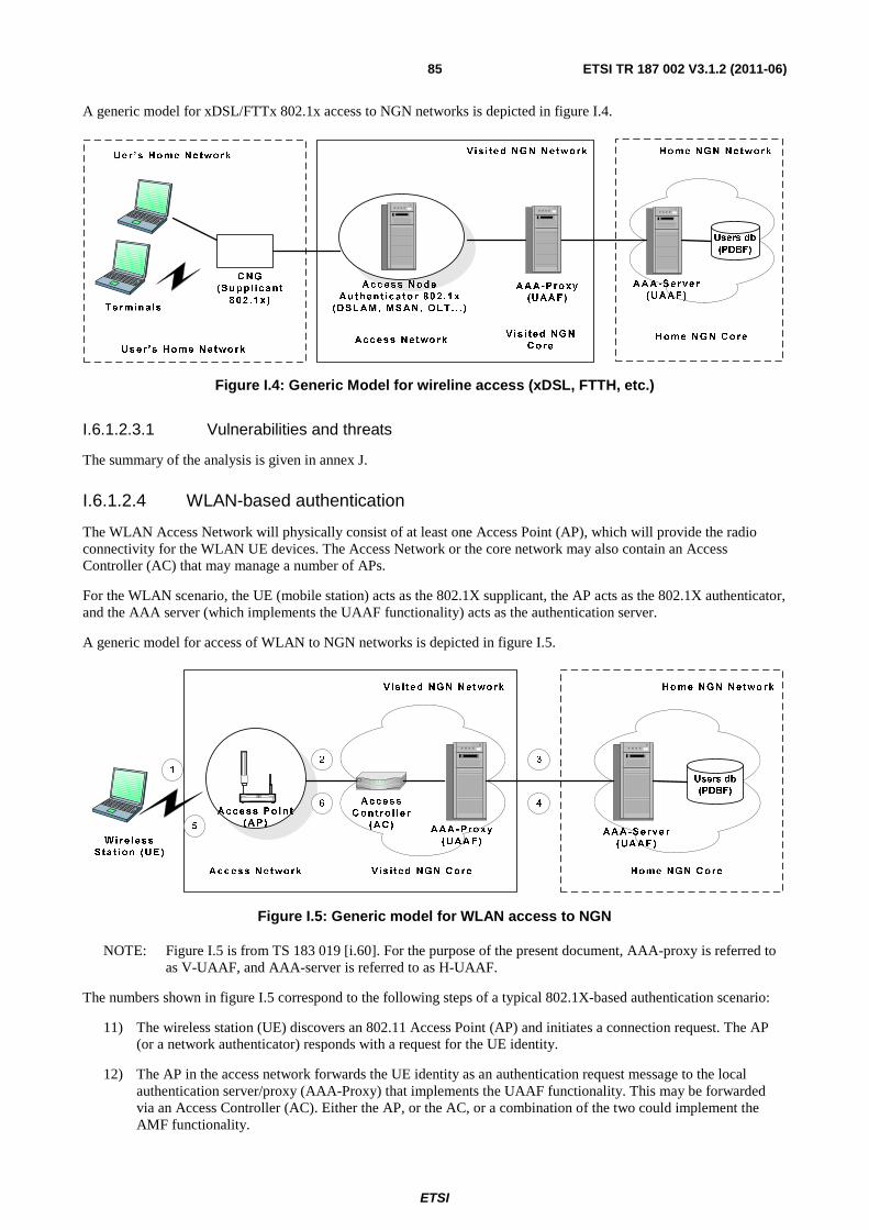
ETSI
ETSI TR 187 002 V3.1.2 (2011-06) 85
A generic model for xDSL/FTTx 802.1x access to NGN networks is depicted in figure I.4.
Figure I.4: Generic Model for wireline access (xDSL, FTTH, etc.)
I.6.1.2.3.1 Vulnerabilities and threats
The summary of the analysis is given in annex J.
I.6.1.2.4 WLAN-based authentication
The WLAN Access Network will physically consist of at least one Access Point (AP), which will provide the radio connectivity for the WLAN UE devices. The Access Network or the core network may also contain an Access Controller (AC) that may manage a number of APs.
For the WLAN scenario, the UE (mobile station) acts as the 802.1X supplicant, the AP acts as the 802.1X authenticator, and the AAA server (which implements the UAAF functionality) acts as the authentication server.
A generic model for access of WLAN to NGN networks is depicted in figure I.5.
Figure I.5: Generic model for WLAN access to NGN
NOTE: Figure I.5 is from TS 183 019 [i.60]. For the purpose of the present document, AAA-proxy is referred to as V-UAAF, and AAA-server is referred to as H-UAAF.
The numbers shown in figure I.5 correspond to the following steps of a typical 802.1X-based authentication scenario:
11) The wireless station (UE) discovers an 802.11 Access Point (AP) and initiates a connection request. The AP (or a network authenticator) responds with a request for the UE identity.
12) The AP in the access network forwards the UE identity as an authentication request message to the local authentication server/proxy (AAA-Proxy) that implements the UAAF functionality. This may be forwarded via an Access Controller (AC). Either the AP, or the AC, or a combination of the two could implement the AMF functionality.
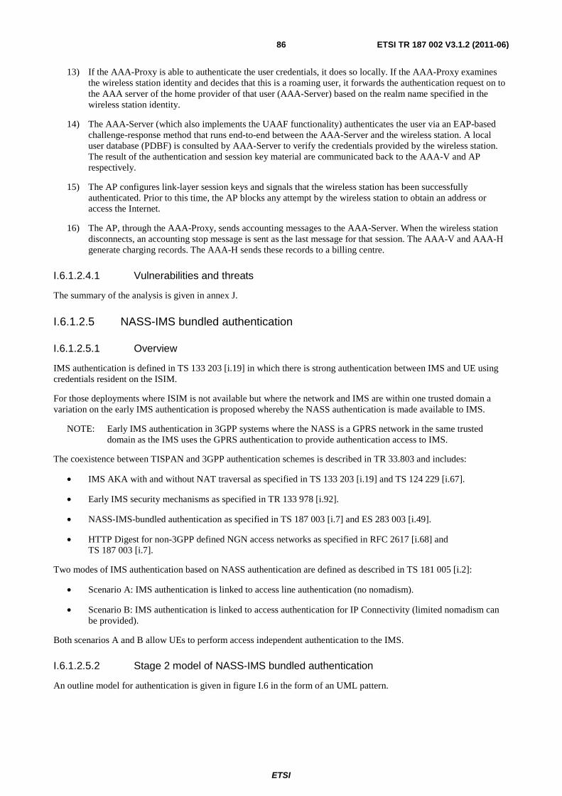
ETSI
ETSI TR 187 002 V3.1.2 (2011-06) 86
13) If the AAA-Proxy is able to authenticate the user credentials, it does so locally. If the AAA-Proxy examines the wireless station identity and decides that this is a roaming user, it forwards the authentication request on to the AAA server of the home provider of that user (AAA-Server) based on the realm name specified in the wireless station identity.
14) The AAA-Server (which also implements the UAAF functionality) authenticates the user via an EAP-based challenge-response method that runs end-to-end between the AAA-Server and the wireless station. A local user database (PDBF) is consulted by AAA-Server to verify the credentials provided by the wireless station. The result of the authentication and session key material are communicated back to the AAA-V and AP respectively.
15) The AP configures link-layer session keys and signals that the wireless station has been successfully authenticated. Prior to this time, the AP blocks any attempt by the wireless station to obtain an address or access the Internet.
16) The AP, through the AAA-Proxy, sends accounting messages to the AAA-Server. When the wireless station disconnects, an accounting stop message is sent as the last message for that session. The AAA-V and AAA-H generate charging records. The AAA-H sends these records to a billing centre.
I.6.1.2.4.1 Vulnerabilities and threats
The summary of the analysis is given in annex J.
I.6.1.2.5 NASS-IMS bundled authentication
I.6.1.2.5.1 Overview
IMS authentication is defined in TS 133 203 [i.19] in which there is strong authentication between IMS and UE using credentials resident on the ISIM.
For those deployments where ISIM is not available but where the network and IMS are within one trusted domain a variation on the early IMS authentication is proposed whereby the NASS authentication is made available to IMS.
NOTE: Early IMS authentication in 3GPP systems where the NASS is a GPRS network in the same trusted domain as the IMS uses the GPRS authentication to provide authentication access to IMS.
The coexistence between TISPAN and 3GPP authentication schemes is described in TR 33.803 and includes:
• IMS AKA with and without NAT traversal as specified in TS 133 203 [i.19] and TS 124 229 [i.67].
• Early IMS security mechanisms as specified in TR 133 978 [i.92].
• NASS-IMS-bundled authentication as specified in TS 187 003 [i.7] and ES 283 003 [i.49].
• HTTP Digest for non-3GPP defined NGN access networks as specified in RFC 2617 [i.68] and TS 187 003 [i.7].
Two modes of IMS authentication based on NASS authentication are defined as described in TS 181 005 [i.2]:
• Scenario A: IMS authentication is linked to access line authentication (no nomadism).
• Scenario B: IMS authentication is linked to access authentication for IP Connectivity (limited nomadism can be provided).
Both scenarios A and B allow UEs to perform access independent authentication to the IMS.
I.6.1.2.5.2 Stage 2 model of NASS-IMS bundled authentication
An outline model for authentication is given in figure I.6 in the form of an UML pattern.
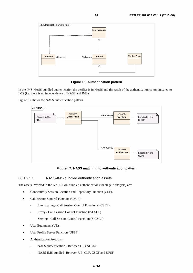
ETSI
ETSI TR 187 002 V3.1.2 (2011-06) 87
cd Authentication architecture
VerifierClaimant
Key_manager
VerifierProxy+Challenges+Responds
Figure I.6: Authentication pattern
In the IMS-NASS bundled authentication the verifier is in NASS and the result of the authentication communicated to IMS (i.e. there is no independence of NASS and IMS).
Figure I.7 shows the NASS authentication pattern.
cd NASS
«asset»Authoriser
«asset»Verifier
«asset»UserProfile Located in the
UUAF
Located in the UUAF
Located in the PDBF
+Accesses
+Accesses
Figure I.7: NASS matching to authentication pattern
I.6.1.2.5.3 NASS-IMS-bundled authentication assets
The assets involved in the NASS-IMS bundled authentication (for stage 2 analysis) are:
• Connectivity Session Location and Repository Function (CLF).
• Call Session Control Function (CSCF):
- Interrogating - Call Session Control Function (I-CSCF).
- Proxy - Call Session Control Function (P-CSCF).
- Serving - Call Session Control Function (S-CSCF).
• User Equipment (UE).
• User Profile Server Function (UPSF).
• Authentication Protocols:
- NASS authentication - Between UE and CLF.
- NASS-IMS bundled -Between UE, CLF, CSCF and UPSF.
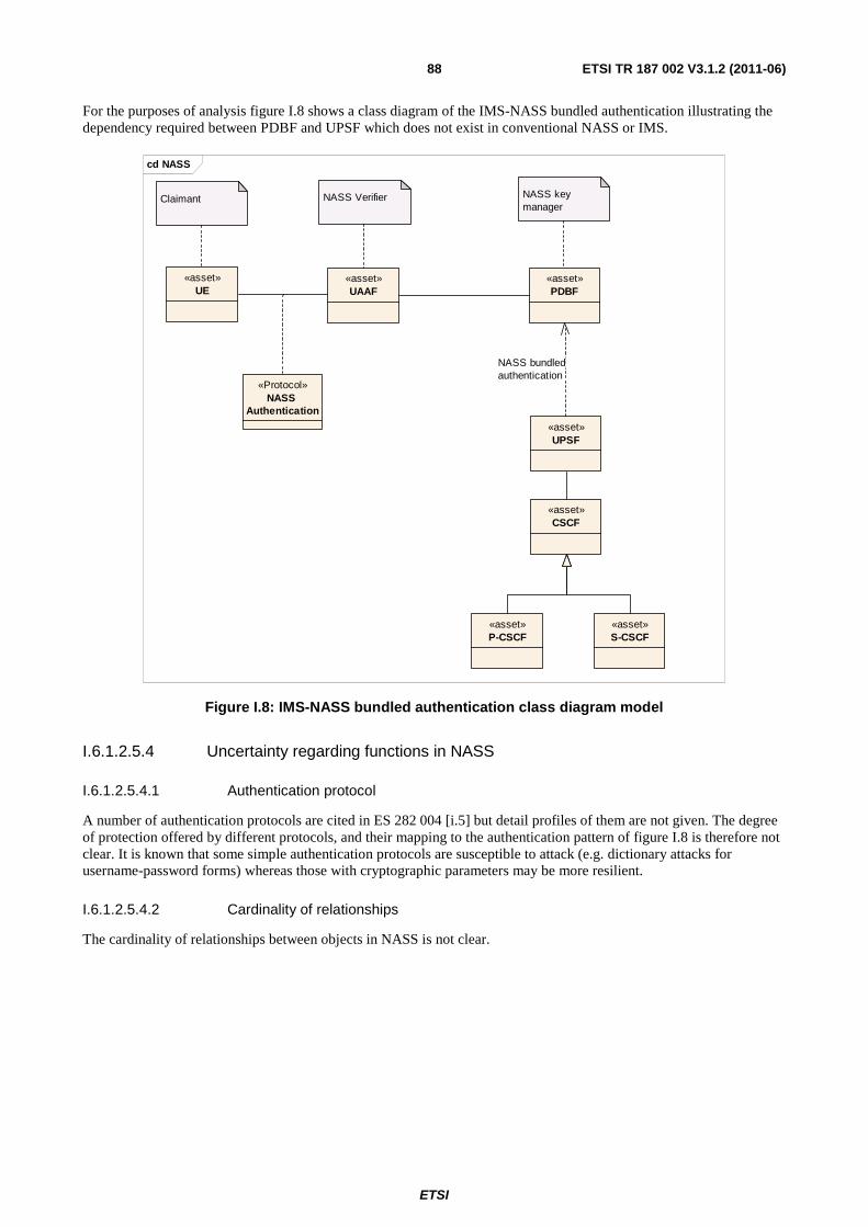
ETSI
ETSI TR 187 002 V3.1.2 (2011-06) 88
For the purposes of analysis figure I.8 shows a class diagram of the IMS-NASS bundled authentication illustrating the dependency required between PDBF and UPSF which does not exist in conventional NASS or IMS.
cd NASS
«asset»UE
«asset»UAAF
«Protocol»NASS
Authentication
Claimant NASS Verifier
«asset»PDBF
NASS key manager
«asset»CSCF
«asset»P-CSCF
«asset»S-CSCF
«asset»UPSF
NASS bundledauthentication
Figure I.8: IMS-NASS bundled authentication class diagram model
I.6.1.2.5.4 Uncertainty regarding functions in NASS
I.6.1.2.5.4.1 Authentication protocol
A number of authentication protocols are cited in ES 282 004 [i.5] but detail profiles of them are not given. The degree of protection offered by different protocols, and their mapping to the authentication pattern of figure I.8 is therefore not clear. It is known that some simple authentication protocols are susceptible to attack (e.g. dictionary attacks for username-password forms) whereas those with cryptographic parameters may be more resilient.
I.6.1.2.5.4.2 Cardinality of relationships
The cardinality of relationships between objects in NASS is not clear.
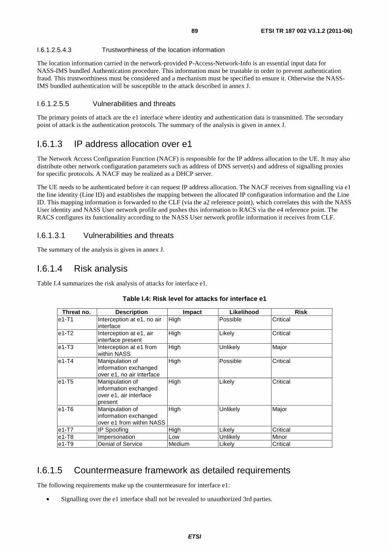
ETSI
ETSI TR 187 002 V3.1.2 (2011-06) 89
I.6.1.2.5.4.3 Trustworthiness of the location information
The location information carried in the network-provided P-Access-Network-Info is an essential input data for NASS-IMS bundled Authentication procedure. This information must be trustable in order to prevent authentication fraud. This trustworthiness must be considered and a mechanism must be specified to ensure it. Otherwise the NASS-IMS bundled authentication will be susceptible to the attack described in annex J.
I.6.1.2.5.5 Vulnerabilities and threats
The primary points of attack are the e1 interface where identity and authentication data is transmitted. The secondary point of attack is the authentication protocols. The summary of the analysis is given in annex J.
I.6.1.3 IP address allocation over e1
The Network Access Configuration Function (NACF) is responsible for the IP address allocation to the UE. It may also distribute other network configuration parameters such as address of DNS server(s) and address of signalling proxies for specific protocols. A NACF may be realized as a DHCP server.
The UE needs to be authenticated before it can request IP address allocation. The NACF receives from signalling via e1 the line identity (Line ID) and establishes the mapping between the allocated IP configuration information and the Line ID. This mapping information is forwarded to the CLF (via the a2 reference point), which correlates this with the NASS User identity and NASS User network profile and pushes this information to RACS via the e4 reference point. The RACS configures its functionality according to the NASS User network profile information it receives from CLF.
I.6.1.3.1 Vulnerabilities and threats
The summary of the analysis is given in annex J.
I.6.1.4 Risk analysis
Table I.4 summarizes the risk analysis of attacks for interface e1.
Table I.4: Risk level for attacks for interface e1
Threat no. Description Impact Likelihood Risk e1-T1 Interception at e1, no air
interface High Possible Critical
e1-T2 Interception at e1, air interface present
High Likely Critical
e1-T3 Interception at e1 from within NASS
High Unlikely Major
e1-T4 Manipulation of information exchanged over e1, no air interface
High Possible Critical
e1-T5 Manipulation of information exchanged over e1, air interface present
High Likely Critical
e1-T6 Manipulation of information exchanged over e1 from within NASS
High Unlikely Major
e1-T7 IP Spoofing High Likely Critical e1-T8 Impersonation Low Unlikely Minor e1-T9 Denial of Service Medium Likely Critical
I.6.1.5 Countermeasure framework as detailed requirements
The following requirements make up the countermeasure for interface e1:
• Signalling over the e1 interface shall not be revealed to unauthorized 3rd parties.
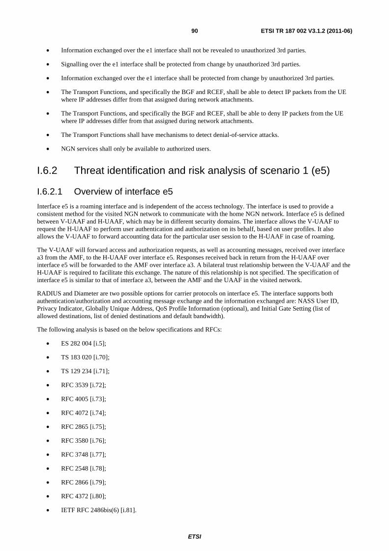
ETSI
ETSI TR 187 002 V3.1.2 (2011-06) 90
• Information exchanged over the e1 interface shall not be revealed to unauthorized 3rd parties.
• Signalling over the e1 interface shall be protected from change by unauthorized 3rd parties.
• Information exchanged over the e1 interface shall be protected from change by unauthorized 3rd parties.
• The Transport Functions, and specifically the BGF and RCEF, shall be able to detect IP packets from the UE where IP addresses differ from that assigned during network attachments.
• The Transport Functions, and specifically the BGF and RCEF, shall be able to deny IP packets from the UE where IP addresses differ from that assigned during network attachments.
• The Transport Functions shall have mechanisms to detect denial-of-service attacks.
• NGN services shall only be available to authorized users.
I.6.2 Threat identification and risk analysis of scenario 1 (e5)
I.6.2.1 Overview of interface e5
Interface e5 is a roaming interface and is independent of the access technology. The interface is used to provide a consistent method for the visited NGN network to communicate with the home NGN network. Interface e5 is defined between V-UAAF and H-UAAF, which may be in different security domains. The interface allows the V-UAAF to request the H-UAAF to perform user authentication and authorization on its behalf, based on user profiles. It also allows the V-UAAF to forward accounting data for the particular user session to the H-UAAF in case of roaming.
The V-UAAF will forward access and authorization requests, as well as accounting messages, received over interface a3 from the AMF, to the H-UAAF over interface e5. Responses received back in return from the H-UAAF over interface e5 will be forwarded to the AMF over interface a3. A bilateral trust relationship between the V-UAAF and the H-UAAF is required to facilitate this exchange. The nature of this relationship is not specified. The specification of interface e5 is similar to that of interface a3, between the AMF and the UAAF in the visited network.
RADIUS and Diameter are two possible options for carrier protocols on interface e5. The interface supports both authentication/authorization and accounting message exchange and the information exchanged are: NASS User ID, Privacy Indicator, Globally Unique Address, QoS Profile Information (optional), and Initial Gate Setting (list of allowed destinations, list of denied destinations and default bandwidth).
The following analysis is based on the below specifications and RFCs:
• ES 282 004 [i.5];
• TS 183 020 [i.70];
• TS 129 234 [i.71];
• RFC 3539 [i.72];
• RFC 4005 [i.73];
• RFC 4072 [i.74];
• RFC 2865 [i.75];
• RFC 3580 [i.76];
• RFC 3748 [i.77];
• RFC 2548 [i.78];
• RFC 2866 [i.79];
• RFC 4372 [i.80];
• IETF RFC 2486bis(6) [i.81].
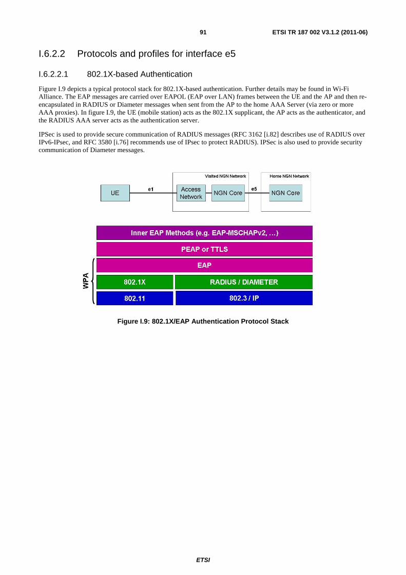
ETSI
ETSI TR 187 002 V3.1.2 (2011-06) 91
I.6.2.2 Protocols and profiles for interface e5
I.6.2.2.1 802.1X-based Authentication
Figure I.9 depicts a typical protocol stack for 802.1X-based authentication. Further details may be found in Wi-Fi Alliance. The EAP messages are carried over EAPOL (EAP over LAN) frames between the UE and the AP and then re-encapsulated in RADIUS or Diameter messages when sent from the AP to the home AAA Server (via zero or more AAA proxies). In figure I.9, the UE (mobile station) acts as the 802.1X supplicant, the AP acts as the authenticator, and the RADIUS AAA server acts as the authentication server.
IPSec is used to provide secure communication of RADIUS messages (RFC 3162 [i.82] describes use of RADIUS over IPv6-IPsec, and RFC 3580 [i.76] recommends use of IPsec to protect RADIUS). IPSec is also used to provide security communication of Diameter messages.
Figure I.9: 802.1X/EAP Authentication Protocol Stack
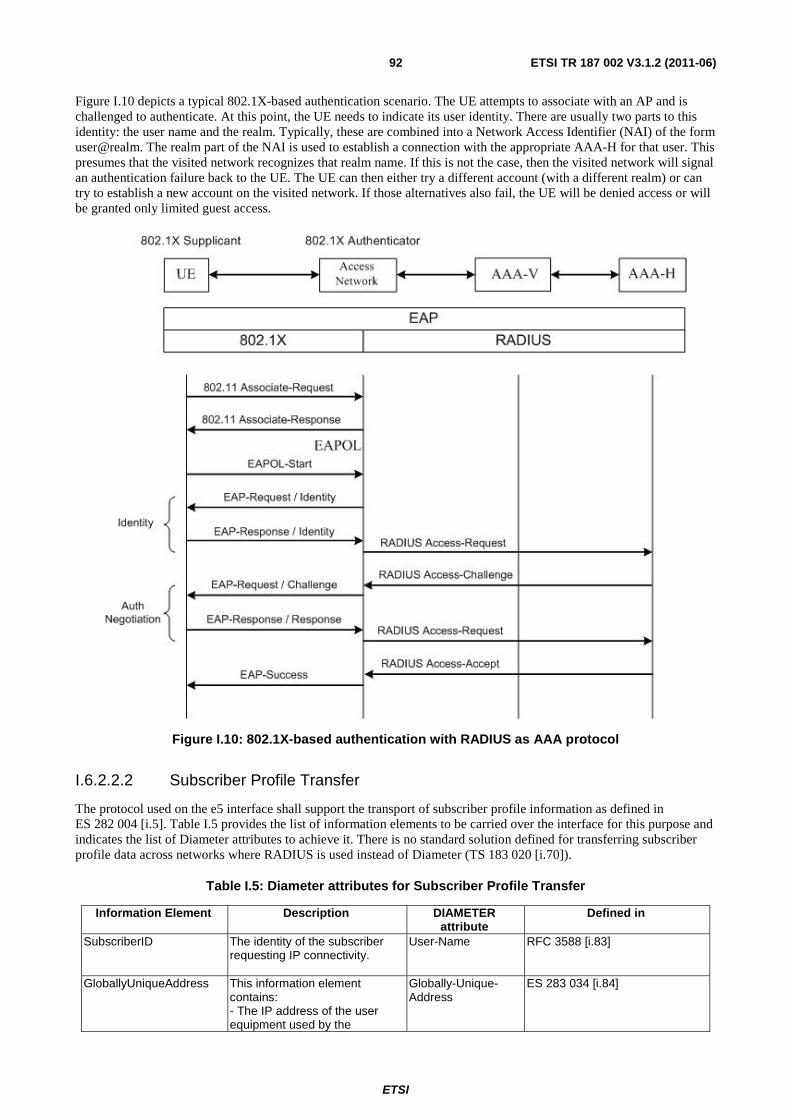
ETSI
ETSI TR 187 002 V3.1.2 (2011-06) 92
Figure I.10 depicts a typical 802.1X-based authentication scenario. The UE attempts to associate with an AP and is challenged to authenticate. At this point, the UE needs to indicate its user identity. There are usually two parts to this identity: the user name and the realm. Typically, these are combined into a Network Access Identifier (NAI) of the form user@realm. The realm part of the NAI is used to establish a connection with the appropriate AAA-H for that user. This presumes that the visited network recognizes that realm name. If this is not the case, then the visited network will signal an authentication failure back to the UE. The UE can then either try a different account (with a different realm) or can try to establish a new account on the visited network. If those alternatives also fail, the UE will be denied access or will be granted only limited guest access.
Figure I.10: 802.1X-based authentication with RADIUS as AAA protocol
I.6.2.2.2 Subscriber Profile Transfer
The protocol used on the e5 interface shall support the transport of subscriber profile information as defined in ES 282 004 [i.5]. Table I.5 provides the list of information elements to be carried over the interface for this purpose and indicates the list of Diameter attributes to achieve it. There is no standard solution defined for transferring subscriber profile data across networks where RADIUS is used instead of Diameter (TS 183 020 [i.70]).
Table I.5: Diameter attributes for Subscriber Profile Transfer
Information Element Description DIAMETER attribute
Defined in
SubscriberID The identity of the subscriber requesting IP connectivity.
User-Name RFC 3588 [i.83]
GloballyUniqueAddress This information element contains: - The IP address of the user equipment used by the
Globally-Unique-Address
ES 283 034 [i.84]
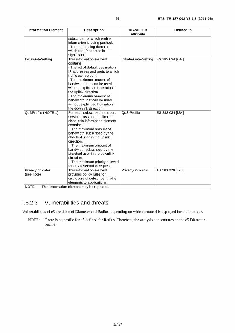
ETSI
ETSI TR 187 002 V3.1.2 (2011-06) 93
Information Element Description DIAMETER attribute
Defined in
subscriber for which profile information is being pushed. - The addressing domain in which the IP address is significant.
InitialGateSetting This information element contains: - The list of default destination IP addresses and ports to which traffic can be sent. - The maximum amount of bandwidth that can be used without explicit authorisation in the uplink direction. - The maximum amount of bandwidth that can be used without explicit authorisation in the downlink direction.
Initiate-Gate-Setting ES 283 034 [i.84]
QoSProfile (NOTE 1) For each subscribed transport service class and application class, this information element contains: - The maximum amount of bandwidth subscribed by the attached user in the uplink direction. - The maximum amount of bandwidth subscribed by the attached user in the downlink direction. - The maximum priority allowed for any reservation request.
QoS-Profile ES 283 034 [i.84]
PrivacyIndicator (see note)
This information element provides policy rules for disclosure of subscriber profile elements to applications.
Privacy-Indicator TS 183 020 [i.70]
NOTE: This information element may be repeated.
I.6.2.3 Vulnerabilities and threats
Vulnerabilities of e5 are those of Diameter and Radius, depending on which protocol is deployed for the interface.
NOTE: There is no profile for e5 defined for Radius. Therefore, the analysis concentrates on the e5 Diameter profile.
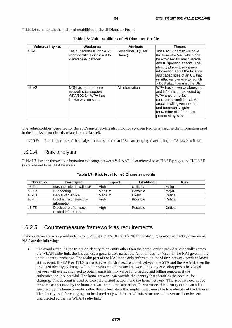
ETSI
ETSI TR 187 002 V3.1.2 (2011-06) 94
Table I.6 summarizes the main vulnerabilities of the e5 Diameter Profile.
Table I.6: Vulnerabilities of e5 Diameter Profile
Vulnerability no. Weakness Attribute Threats e5-V1 The subscriber ID or NASS
user identity is disclosed to visited NGN network
SubscriberID (User-Name)
The NASS identity will have the form of a NAI, which can be exploited for masquerade and IP spoofing attacks. The identity phase also carries information about the location and capabilities of an UE that an attacker can use to launch a DoS attack against the UE.
e5-V2 NGN visited and home network shall support WPA/802.1x. WPA has known weaknesses.
All information WPA has known weaknesses and information protected by WPA should not be considered confidential. An attacker will, given the time and opportunity, gain knowledge of information protected by WPA.
The vulnerabilities identified for the e5 Diameter profile also hold for e5 when Radius is used, as the information used in the attacks is not directly related to interface e5.
NOTE: For the purpose of the analysis it is assumed that IPSec are employed according to TS 133 210 [i.13].
I.6.2.4 Risk analysis
Table I.7 lists the threats to information exchange between V-UAAF (also referred to as UAAF-proxy) and H-UAAF (also referred to as UAAF-server)
Table I.7: Risk level for e5 Diameter profile
Threat no. Description Impact Likelihood Risk e5-T1 Masquerade as valid UE High Unlikely Major e5-T2 IP spoofing Medium Possible Major e5-T3 Denial of Service Medium Likely Critical e5-T4 Disclosure of sensitive
information High Possible Critical
e5-T5 Disclosure of privacy-related information
High Possible Critical
I.6.2.5 Countermeasure framework as requirements
The countermeasure proposed in ES 282 004 [i.5] and TS 183 020 [i.70] for protecting subscriber identity (user name, NAI) are the following:
• "To avoid revealing the true user identity to an entity other than the home service provider, especially across the WLAN radio link, the UE can use a generic user name like "anonymous" or "user" in the NAI given in the initial identity exchange. The realm part of the NAI is the only information the visited network needs to know at this point. If PEAP or TTLS are used to establish a secure tunnel between the STA and the AAA-H, then the protected identity exchange will not be visible to the visited network or to any eavesdroppers. The visited network will eventually need to obtain some identity value for charging and billing purposes if the authentication is successful. The home network can provide the identity that identifies the account for charging. This account is used between the visited network and the home network. This account need not be the same as that used by the home network to bill the subscriber. Furthermore, this identity can be an alias specified by the home provider rather than information that might compromise the true identity of the UE user. The identity used for charging can be shared only with the AAA infrastructure and never needs to be sent unprotected across the WLAN radio link."
ETSI
ETSI TR 187 002 V3.1.2 (2011-06) 95
The problem with this countermeasure is that the UE needs to be identifiable to the home NGN network. This means that the alias must be a pseudonym known only to the home network. This leads to the following requirements:
• The user identity visible to the visited NGN network should be pseudonymous.
• The pseudonymous user identity should only be resolvable by the home NGN network.
• There should be means to enable confidentiality protection on all communication over interface e5.
TS 183 020 [i.70] specifies that WPA/802.1x is mandatory to support for the home NGN network and that WPA2 is optional. This is an identified weakness of NASS (see table I.6). To remove this weakness, the following requirements should be added to 187 001:
• The visited NGN network should support WPA2.
• The home NGN network should support WPA2.
I.6.3 Threat identification and risk analysis of scenarios 5-11 (e2)
I.6.3.1 Overview of interface e2
This reference point enables Application Functions (AF) to retrieve information about the characteristics of the IP-connectivity session used to access NGN services and applications (e.g. network location information) from the CLF.
The form of location information that is provided by the CLF depends on the requestor.
The following information flows are exchanged between the CLF and AF over interface e2:
• Information Query Request.
• Information Query Response.
• Event Registration Request.
• Event Registration Response.
• Notification Event Request.
• Notification Event Response.
The threat analysis of information exchanged over interface e2 is based on the following documents:
• ES 283 035 [i.85];
• TS 129 329 [i.86];
• TS 133 210 [i.13];
• RFC 3588 [i.83];
• RFC 3554 [i.87];
• RFC 2960 [i.88];
• RFC 3309 [i.89];
• ES 283 034 [i.84];
• RFC 4005 [i.73];
• RFC 4201 [i.90] and RFC 4301 [i.91].
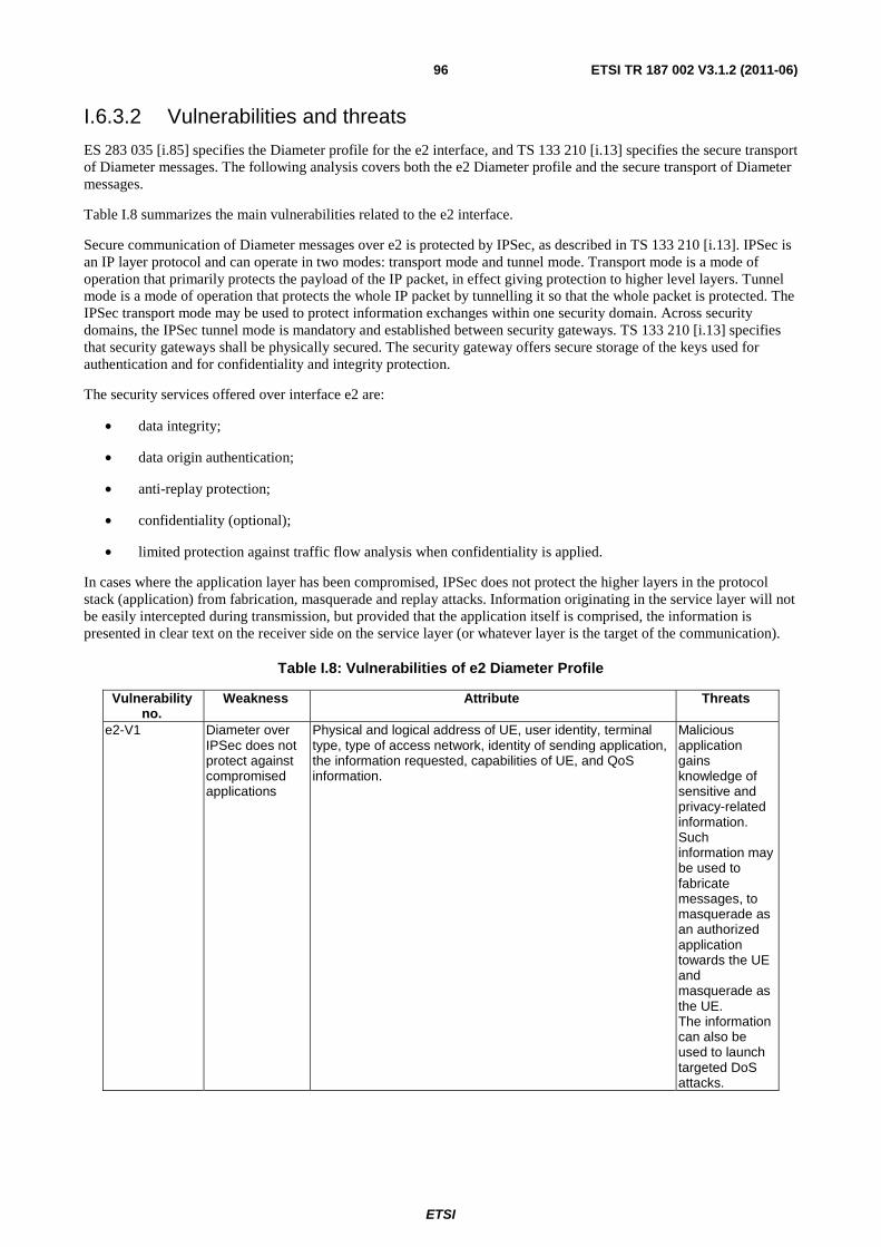
ETSI
ETSI TR 187 002 V3.1.2 (2011-06) 96
I.6.3.2 Vulnerabilities and threats
ES 283 035 [i.85] specifies the Diameter profile for the e2 interface, and TS 133 210 [i.13] specifies the secure transport of Diameter messages. The following analysis covers both the e2 Diameter profile and the secure transport of Diameter messages.
Table I.8 summarizes the main vulnerabilities related to the e2 interface.
Secure communication of Diameter messages over e2 is protected by IPSec, as described in TS 133 210 [i.13]. IPSec is an IP layer protocol and can operate in two modes: transport mode and tunnel mode. Transport mode is a mode of operation that primarily protects the payload of the IP packet, in effect giving protection to higher level layers. Tunnel mode is a mode of operation that protects the whole IP packet by tunnelling it so that the whole packet is protected. The IPSec transport mode may be used to protect information exchanges within one security domain. Across security domains, the IPSec tunnel mode is mandatory and established between security gateways. TS 133 210 [i.13] specifies that security gateways shall be physically secured. The security gateway offers secure storage of the keys used for authentication and for confidentiality and integrity protection.
The security services offered over interface e2 are:
• data integrity;
• data origin authentication;
• anti-replay protection;
• confidentiality (optional);
• limited protection against traffic flow analysis when confidentiality is applied.
In cases where the application layer has been compromised, IPSec does not protect the higher layers in the protocol stack (application) from fabrication, masquerade and replay attacks. Information originating in the service layer will not be easily intercepted during transmission, but provided that the application itself is comprised, the information is presented in clear text on the receiver side on the service layer (or whatever layer is the target of the communication).
Table I.8: Vulnerabilities of e2 Diameter Profile
Vulnerability no.
Weakness Attribute Threats
e2-V1 Diameter over IPSec does not protect against compromised applications
Physical and logical address of UE, user identity, terminal type, type of access network, identity of sending application, the information requested, capabilities of UE, and QoS information.
Malicious application gains knowledge of sensitive and privacy-related information. Such information may be used to fabricate messages, to masquerade as an authorized application towards the UE and masquerade as the UE. The information can also be used to launch targeted DoS attacks.
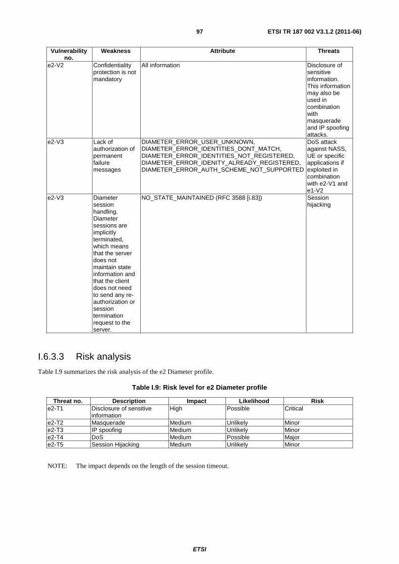
ETSI
ETSI TR 187 002 V3.1.2 (2011-06) 97
Vulnerability no.
Weakness Attribute Threats
e2-V2 Confidentiality protection is not mandatory
All information Disclosure of sensitive information. This information may also be used in combination with masquerade and IP spoofing attacks.
e2-V3 Lack of authorization of permanent failure messages
DIAMETER_ERROR_USER_UNKNOWN, DIAMETER_ERROR_IDENTITIES_DONT_MATCH, DIAMETER_ERROR_IDENTITIES_NOT_REGISTERED, DIAMETER_ERROR_IDENITY_ALREADY_REGISTERED, DIAMETER_ERROR_AUTH_SCHEME_NOT_SUPPORTED
DoS attack against NASS, UE or specific applications if exploited in combination with e2-V1 and e1-V2
e2-V3 Diameter session handling. Diameter sessions are implicitly terminated, which means that the server does not maintain state information and that the client does not need to send any re-authorization or session termination request to the server.
NO_STATE_MAINTAINED (RFC 3588 [i.83]) Session hijacking
I.6.3.3 Risk analysis
Table I.9 summarizes the risk analysis of the e2 Diameter profile.
Table I.9: Risk level for e2 Diameter profile
Threat no. Description Impact Likelihood Risk e2-T1 Disclosure of sensitive
information High Possible Critical
e2-T2 Masquerade Medium Unlikely Minor e2-T3 IP spoofing Medium Unlikely Minor e2-T4 DoS Medium Possible Major e2-T5 Session Hijacking Medium Unlikely Minor
NOTE: The impact depends on the length of the session timeout.
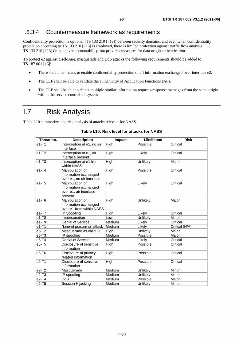
ETSI
ETSI TR 187 002 V3.1.2 (2011-06) 98
I.6.3.4 Countermeasure framework as requirements
Confidentiality protection is optional (TS 133 210 [i.13]) between security domains, and even when confidentiality protection according to TS 133 210 [i.13] is employed, there is limited protection against traffic flow analysis. TS 133 210 [i.13] do not cover accountability, but provides measures for data origin authentication.
To protect e2 against disclosure, masquerade and DoS attacks the following requirements should be added to TS 187 001 [i.6]:
• There should be means to enable confidentiality protection of all information exchanged over interface e2.
• The CLF shall be able to validate the authenticity of Application Functions (AF).
• The CLF shall be able to detect multiple similar information requests/response messages from the same origin within the service control subsystems.
I.7 Risk Analysis Table I.10 summarizes the risk analysis of attacks relevant for NASS.
Table I.10: Risk level for attacks for NASS
Threat no. Description Impact Likelihood Risk e1-T1 Interception at e1, no air
interface High Possible Critical
e1-T2 Interception at e1, air interface present
High Likely Critical
e1-T3 Interception at e1 from within NASS
High Unlikely Major
e1-T4 Manipulation of information exchanged over e1, no air interface
High Possible Critical
e1-T5 Manipulation of information exchanged over e1, air interface present
High Likely Critical
e1-T6 Manipulation of information exchanged over e1 from within NASS
High Unlikely Major
e1-T7 IP Spoofing High Likely Critical e1-T8 Impersonation Low Unlikely Minor e1-T9 Denial of Service Medium Likely Critical e1-T1 "Line-id poisoning" attack Medium Likely Critical (N/A) e5-T2 Masquerade as valid UE High Unlikely Major e5-T3 IP spoofing Medium Possible Major e5-T4 Denial of Service Medium Likely Critical e5-T5 Disclosure of sensitive
information High Possible Critical
e5-T6 Disclosure of privacy-related information
High Possible Critical
e2-T1 Disclosure of sensitive information
High Possible Critical
e2-T2 Masquerade Medium Unlikely Minor e2-T3 IP spoofing Medium Unlikely Minor e2-T4 DoS Medium Possible Major e2-T5 Session Hijacking Medium Unlikely Minor
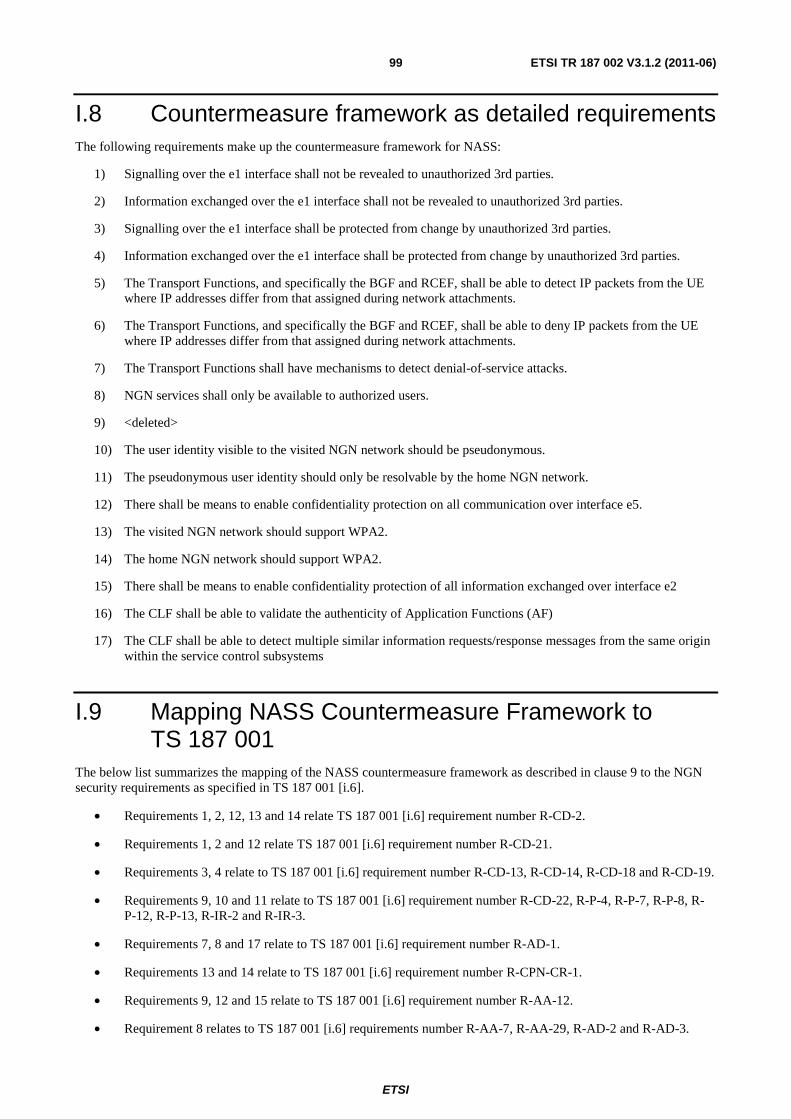
ETSI
ETSI TR 187 002 V3.1.2 (2011-06) 99
I.8 Countermeasure framework as detailed requirements The following requirements make up the countermeasure framework for NASS:
1) Signalling over the e1 interface shall not be revealed to unauthorized 3rd parties.
2) Information exchanged over the e1 interface shall not be revealed to unauthorized 3rd parties.
3) Signalling over the e1 interface shall be protected from change by unauthorized 3rd parties.
4) Information exchanged over the e1 interface shall be protected from change by unauthorized 3rd parties.
5) The Transport Functions, and specifically the BGF and RCEF, shall be able to detect IP packets from the UE where IP addresses differ from that assigned during network attachments.
6) The Transport Functions, and specifically the BGF and RCEF, shall be able to deny IP packets from the UE where IP addresses differ from that assigned during network attachments.
7) The Transport Functions shall have mechanisms to detect denial-of-service attacks.
8) NGN services shall only be available to authorized users.
9) <deleted>
10) The user identity visible to the visited NGN network should be pseudonymous.
11) The pseudonymous user identity should only be resolvable by the home NGN network.
12) There shall be means to enable confidentiality protection on all communication over interface e5.
13) The visited NGN network should support WPA2.
14) The home NGN network should support WPA2.
15) There shall be means to enable confidentiality protection of all information exchanged over interface e2
16) The CLF shall be able to validate the authenticity of Application Functions (AF)
17) The CLF shall be able to detect multiple similar information requests/response messages from the same origin within the service control subsystems
I.9 Mapping NASS Countermeasure Framework to TS 187 001
The below list summarizes the mapping of the NASS countermeasure framework as described in clause 9 to the NGN security requirements as specified in TS 187 001 [i.6].
• Requirements 1, 2, 12, 13 and 14 relate TS 187 001 [i.6] requirement number R-CD-2.
• Requirements 1, 2 and 12 relate TS 187 001 [i.6] requirement number R-CD-21.
• Requirements 3, 4 relate to TS 187 001 [i.6] requirement number R-CD-13, R-CD-14, R-CD-18 and R-CD-19.
• Requirements 9, 10 and 11 relate to TS 187 001 [i.6] requirement number R-CD-22, R-P-4, R-P-7, R-P-8, R-P-12, R-P-13, R-IR-2 and R-IR-3.
• Requirements 7, 8 and 17 relate to TS 187 001 [i.6] requirement number R-AD-1.
• Requirements 13 and 14 relate to TS 187 001 [i.6] requirement number R-CPN-CR-1.
• Requirements 9, 12 and 15 relate to TS 187 001 [i.6] requirement number R-AA-12.
• Requirement 8 relates to TS 187 001 [i.6] requirements number R-AA-7, R-AA-29, R-AD-2 and R-AD-3.
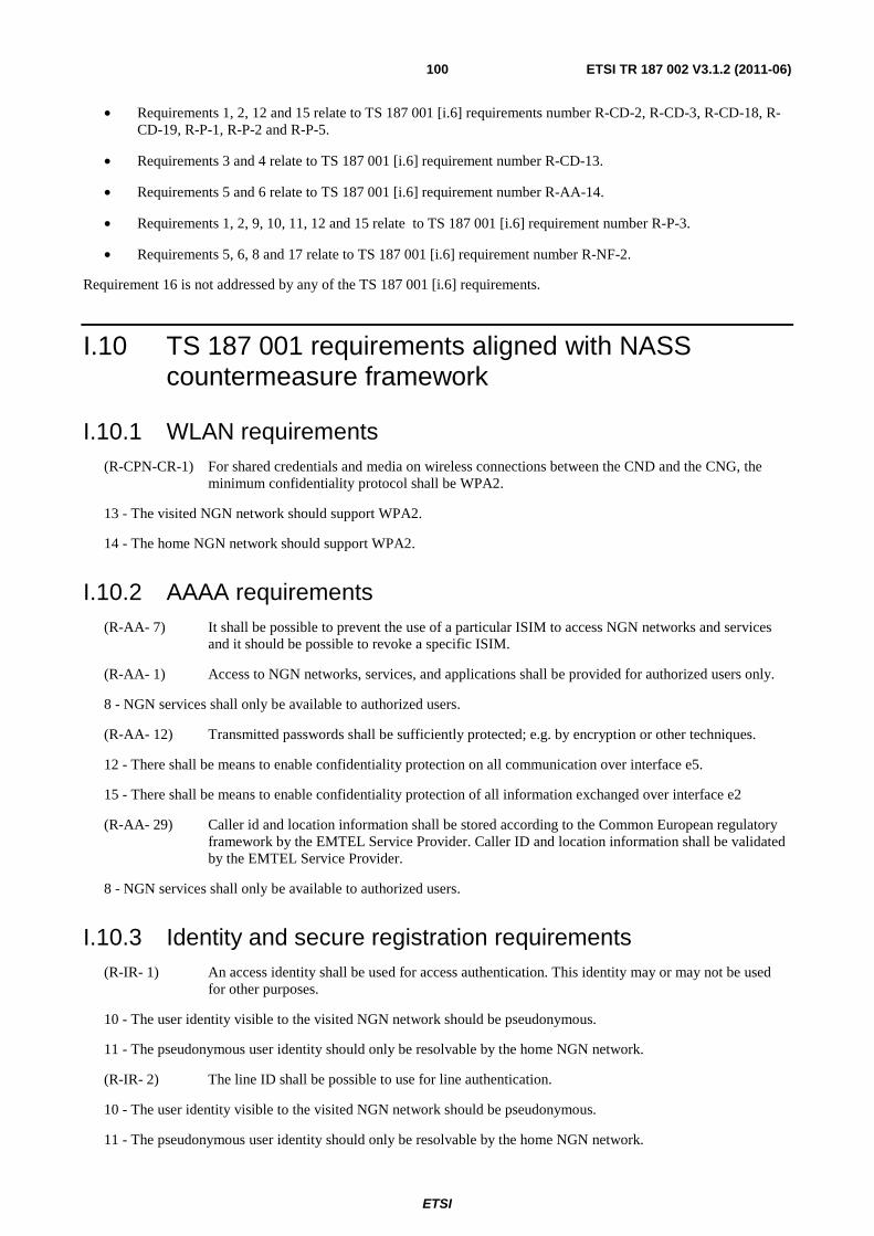
ETSI
ETSI TR 187 002 V3.1.2 (2011-06) 100
• Requirements 1, 2, 12 and 15 relate to TS 187 001 [i.6] requirements number R-CD-2, R-CD-3, R-CD-18, R-CD-19, R-P-1, R-P-2 and R-P-5.
• Requirements 3 and 4 relate to TS 187 001 [i.6] requirement number R-CD-13.
• Requirements 5 and 6 relate to TS 187 001 [i.6] requirement number R-AA-14.
• Requirements 1, 2, 9, 10, 11, 12 and 15 relate to TS 187 001 [i.6] requirement number R-P-3.
• Requirements 5, 6, 8 and 17 relate to TS 187 001 [i.6] requirement number R-NF-2.
Requirement 16 is not addressed by any of the TS 187 001 [i.6] requirements.
I.10 TS 187 001 requirements aligned with NASS countermeasure framework
I.10.1 WLAN requirements (R-CPN-CR-1) For shared credentials and media on wireless connections between the CND and the CNG, the
minimum confidentiality protocol shall be WPA2.
13 - The visited NGN network should support WPA2.
14 - The home NGN network should support WPA2.
I.10.2 AAAA requirements (R-AA- 7) It shall be possible to prevent the use of a particular ISIM to access NGN networks and services
and it should be possible to revoke a specific ISIM.
(R-AA- 1) Access to NGN networks, services, and applications shall be provided for authorized users only.
8 - NGN services shall only be available to authorized users.
(R-AA- 12) Transmitted passwords shall be sufficiently protected; e.g. by encryption or other techniques.
12 - There shall be means to enable confidentiality protection on all communication over interface e5.
15 - There shall be means to enable confidentiality protection of all information exchanged over interface e2
(R-AA- 29) Caller id and location information shall be stored according to the Common European regulatory framework by the EMTEL Service Provider. Caller ID and location information shall be validated by the EMTEL Service Provider.
8 - NGN services shall only be available to authorized users.
I.10.3 Identity and secure registration requirements (R-IR- 1) An access identity shall be used for access authentication. This identity may or may not be used
for other purposes.
10 - The user identity visible to the visited NGN network should be pseudonymous.
11 - The pseudonymous user identity should only be resolvable by the home NGN network.
(R-IR- 2) The line ID shall be possible to use for line authentication.
10 - The user identity visible to the visited NGN network should be pseudonymous.
11 - The pseudonymous user identity should only be resolvable by the home NGN network.
ETSI
ETSI TR 187 002 V3.1.2 (2011-06) 101
I.10.4 Privacy requirements (R-P- 16) It shall be possible to protect the network topology from exposure toward other domains. It shall
also be possible for a security domains to define and implement protection against traffic analysis for signalling and management protocols.
1 - Signalling over the e1 interface shall not be revealed to unauthorized 3rd parties.
2 - Information exchanged over the e1 interface shall not be revealed to unauthorized 3rd parties.
12 - There shall be means to enable confidentiality protection on all communication over interface e5.
15 - There shall be means to enable confidentiality protection of all information exchanged over interface e2
(R-P- 17) User location and usage patterns shall be kept from unwanted disclosure.
1 - Signalling over the e1 interface shall not be revealed to unauthorized 3rd parties.
2 - Information exchanged over the e1 interface shall not be revealed to unauthorized 3rd parties.
12 - There shall be means to enable confidentiality protection on all communication over interface e5.
15 - There shall be means to enable confidentiality protection of all information exchanged over interface e2
(R-P- 18) It shall be possible to protect the confidentiality of user identity data.
1 - Signalling over the e1 interface shall not be revealed to unauthorized 3rd parties.
2 - Information exchanged over the e1 interface shall not be revealed to unauthorized 3rd parties.
9 - The NASS user identity shall not be disclosed to unauthorized 3rd parties.
10 - The user identity visible to the visited NGN network should be pseudonymous.
11 - The pseudonymous user identity should only be resolvable by the home NGN network.
12 - There shall be means to enable confidentiality protection on all communication over interface e5.
15 - There shall be means to enable confidentiality protection of all information exchanged over interface e2
(R-P- 19) Anonymous communication sessions shall be supported in NGN either in a permanent mode or in a temporary mode communication by call. In this case the originating party identity shall not be presented to the destination party. The network to which the destination party is connected to is responsible to handle this service.
9 - The NASS user identity not be disclosed to unauthorized 3rd parties.
10 - The user identity visible to the visited NGN network should be pseudonymous.
11 - The pseudonymous user identity should only be resolvable by the home NGN network.
(R-P- 20) NGN shall support the specific case where the destination party has an override right (e.g. emergency communication sessions), and the originating party identity is provided to the destination party independent whether or not this communication session is anonymous.
1 - Signalling over the e1 interface shall not be revealed to unauthorized 3rd parties.
2 - Information exchanged over the e1 interface shall not be revealed to unauthorized 3rd parties.
12 - There shall be means to enable confidentiality protection on all communication over interface e5.
15 - There shall be means to enable confidentiality protection of all information exchanged over interface e2
(R-P- 21) The NGN shall support mechanisms for the network operator to guarantee the authenticity of a user identity presented for an incoming call to a user where the call is wholly within that operator's network (i.e. originating and terminating parties are subscribers to, and resident in, a single NGN).
ETSI
ETSI TR 187 002 V3.1.2 (2011-06) 102
9 - The NASS user identity shall not be disclosed to unauthorized 3rd parties.
10 - The user identity visible to the visited NGN network should be pseudonymous.
11 - The pseudonymous user identity should only be resolvable by the home NGN network.
(R-P- 22) The NGN shall provide mechanisms that allow to present the identity of the session originator, if this is not restricted by the session originator.
9 - The NASS user identity shall not be disclosed to unauthorized 3rd parties.
10 - The user identity visible to the visited NGN network should be pseudonymous.
11 - The pseudonymous user identity should only be resolvable by the home NGN network.
(R-P- 23) It shall be possible for the sender of the message to request to hide its public ID from the recipient.
9 - The NASS user identity shall not be disclosed to unauthorized 3rd parties.
10 - The user identity visible to the visited NGN network should be pseudonymous.
11 - The pseudonymous user identity should only be resolvable by the home NGN network.
(R-P- 24) Users may select the Identity presented when starting a session or sending a message. It shall be possible to verify this identity and to initiate a session or message in reply.
9 - The NASS user identity shall not be disclosed to unauthorized 3rd parties.
10 - The user identity visible to the visited NGN network should be pseudonymous.
11 - The pseudonymous user identity should only be resolvable by the home NGN network.
I.10.5 Communication, data security and confidentiality requirements
(R-CD- 2) Network Domain Security (NDS) shall be provided at the network layer and comply to TS 133 210 [i.13].
1 - Signalling over the e1 interface shall not be revealed to unauthorized 3rd parties.
2 - Information exchanged over the e1 interface shall not be revealed to unauthorized 3rd parties.
12 - There shall be means to enable confidentiality protection on all communication over interface e5.
15 - There shall be means to enable confidentiality protection of all information exchanged over interface e2
(R-CD- 3) All NDS/IP traffic shall pass through a SEGF (Security Gateway Function) before entering or leaving the security domain. IMS operators shall operate NDS/IP Za interface between SEGFs
1 - Signalling over the e1 interface shall not be revealed to unauthorized 3rd parties.
2 - Information exchanged over the e1 interface shall not be revealed to unauthorized 3rd parties.
12 - There shall be means to enable confidentiality protection on all communication over interface e5.
15 - There shall be means to enable confidentiality protection of all information exchanged over interface e2
(R-CD- 7) In the case where IMS authentication is linked to access line authentication the underlying access technology shall provide protection of NGN signalling and user data.
1 - Signalling over the e1 interface shall not be revealed to unauthorized 3rd parties.
2 - Information exchanged over the e1 interface shall not be revealed to unauthorized 3rd parties.
12 - There shall be means to enable confidentiality protection on all communication over interface e5.
ETSI
ETSI TR 187 002 V3.1.2 (2011-06) 103
(R-CD- 13) Integrity protection of signalling, control communications and of stored data shall be provided.
3 - Signalling over the e1 interface shall be protected from change by unauthorized 3rd parties.
4 - Information exchanged over the e1 interface shall be protected from change by unauthorized 3rd parties.
(R-CD- 18) Confidentiality of communications should be achieved by cryptographic encryption. Confidentiality of stored data shall be achieved by cryptographic encryption or by access controls.
1 - Signalling over the e1 interface shall not be revealed to unauthorized 3rd parties.
2 - Information exchanged over the e1 interface shall not be revealed to unauthorized 3rd parties.
12 - There shall be means to enable confidentiality protection on all communication over interface e5.
15 - There shall be means to enable confidentiality protection of all information exchanged over interface e2
(R-CD- 19) Confidentiality of signalling and control messages shall be enforced if required by the application or in environments where the security policy demands confidentiality. The mechanism should allow a choice in the algorithm to be used.
1 - Signalling over the e1 interface shall not be revealed to unauthorized 3rd parties.
2 - Information exchanged over the e1 interface shall not be revealed to unauthorized 3rd parties.
12 - There shall be means to enable confidentiality protection on all communication over interface e5.
15 - There shall be means to enable confidentiality protection of all information exchanged over interface e2
(R-CD- 21) Confidentiality protection between Network Functions (e.g. between CSCFs, or between CSCFs and the HSS) shall rely on mechanisms specified by Network Domain Security in TS 133 210 [i.13].
1 - Signalling over the e1 interface shall not be revealed to unauthorized 3rd parties.
2 - Information exchanged over the e1 interface shall not be revealed to unauthorized 3rd parties.
12 - There shall be means to enable confidentiality protection on all communication over interface e5.
(R-CD- 22) It shall be possible to protect the confidentiality of user-related data which is stored or processed by a provider.
1 - Signalling over the e1 interface shall not be revealed to unauthorized 3rd parties.
2- Information exchanged over the e1 interface shall not be revealed to unauthorized 3rd parties.
9 - The NASS user identity shall not be disclosed to unauthorized 3rd parties.
10 - The user identity visible to the visited NGN network should be pseudonymous.
11 - The pseudonymous user identity should only be resolvable by the home NGN network.
12 - There shall be means to enable confidentiality protection on all communication over interface e5.
15 - There shall be means to enable confidentiality protection of all information exchanged over interface e2
I.10.6 Availability and DoS Protection requirements (R-NF- 2) Filters to screen the IP packets to restrict/grant access to specific bearer streams shall be supported.
5 - The Transport Functions, and specifically the BGF and RCEF, shall be able to detect IP packets from the UE where IP addresses differ from that assigned during network attachments.
6 - The Transport Functions, and specifically the BGF and RCEF, shall be able to deny IP packets from the UE where IP addresses differ from that assigned during network attachments.
8 - NGN services shall only be available to authorized users.
ETSI
ETSI TR 187 002 V3.1.2 (2011-06) 104
17 - The CLF shall be able to detect multiple similar information requests/response messages from the same origin within the service control subsystems
(R-AD- 1) Mechanisms shall be provided to mitigate denial-of-service attacks.
7 - The Transport Functions shall have mechanisms to detect denial-of-service attacks.
8 - NGN services shall only be available to authorized users.
17 - The CLF shall be able to detect multiple similar information requests/response messages from the same origin within the service control subsystems
(R-AD- 2) Provide access control mechanisms to ensure that authorized users only can access the service.
8 - NGN services shall only be available to authorized users.
(R-AD- 3) It shall be possible to prevent intruders from restricting the availability of services by logical means.
8 - NGN services shall only be available to authorized users.
I.11 Residual Risk This clause documents the residual risk from the NASS TVRA. The numbering of the requirements in the below list aligns with that in clause I.9, which gives the complete NASS countermeasure framework.
NOTE: The below requirements have not been addressed in TS 187 001 [i.6] and TS 187 003 [i.7] and is for further study.
1 - Signalling over the e1 interface shall not be revealed to unauthorized 3rd parties.
2 - Information exchanged over the e1 interface shall not be revealed to unauthorized 3rd parties.
3 - Signalling over the e1 interface shall be protected from change by unauthorized 3rd parties.
4 - Information exchanged over the e1 interface shall be protected from change by unauthorized 3rd parties.
5 - The Transport Functions, and specifically the BGF and RCEF, shall be able to detect IP packets from the UE where IP addresses differ from that assigned during network attachments.
6 - The Transport Functions, and specifically the BGF and RCEF, shall be able to deny IP packets from the UE where IP addresses differ from that assigned during network attachments.
13 - The visited NGN network should support WPA2.
14 - The home NGN network should support WPA2.
18) 16 - The CLF shall be able to validate the authenticity of Application Functions (AF)
19) 17 - The CLF shall be able to detect multiple similar information requests/response messages from the same origin within the service control subsystems
I.12 Open issues and topics for further study The NASS TVRA has identified the following open issues:
• What EAP "deployments" are supported in NGN (EAP-SIM and EAP-AKA)?
- The various EAP deployments have distinctive problems. Some are vulnerable to dictionary attacks, plaintext attacks, MiM attacks and Ciphertext attacks.

ETSI
ETSI TR 187 002 V3.1.2 (2011-06) 105
• Secure communication for Diameter messages are IPSec as specified in TS 133 210 [i.13]:
- Confidentiality services should be made mandatory.
- IPSec does not secure the Diameter message as such, it only provides secure communication of Diameter messages over interfaces.
• There is a need for a security profile for Diameter messages in NGN.
• Radius is supported as the protocol for several interfaces, but there is no Radius profile for e5, e4 and e2.
• SIP has know weaknesses that has yet not been addressed.
• Lack of protection of interface e1.
• No direct security association between UE and UAAF in NASS for authentication.
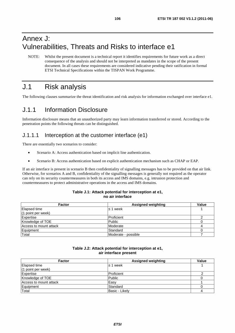
ETSI
ETSI TR 187 002 V3.1.2 (2011-06) 106
Annex J: Vulnerabilities, Threats and Risks to interface e1
NOTE: Whilst the present document is a technical report it identifies requirements for future work as a direct consequence of the analysis and should not be interpreted as mandates in the scope of the present document. In all cases these requirements are considered indicative pending their ratification in formal ETSI Technical Specifications within the TISPAN Work Programme.
J.1 Risk analysis The following clauses summarize the threat identification and risk analysis for information exchanged over interface e1.
J.1.1 Information Disclosure Information disclosure means that an unauthorized party may learn information transferred or stored. According to the penetration points the following threats can be distinguished.
J.1.1.1 Interception at the customer interface (e1)
There are essentially two scenarios to consider:
• Scenario A: Access authentication based on implicit line authentication.
• Scenario B: Access authentication based on explicit authentication mechanism such as CHAP or EAP.
If an air interface is present in scenario B then confidentiality of signalling messages has to be provided on that air link. Otherwise, for scenarios A and B, confidentiality of the signalling messages is generally not required as the operator can rely on its security countermeasures in both its access and IMS domains, e.g. intrusion protection and countermeasures to protect administrative operations in the access and IMS domains.
Table J.1: Attack potential for interception at e1, no air interface
Factor Assigned weighting Value Elapsed time (1 point per week)
≤ 1 week 1
Expertise Proficient 2 Knowledge of TOE Public 0 Access to mount attack Moderate 4 Equipment Standard 0 Total Moderate - possible 7
Table J.2: Attack potential for interception at e1, air interface present
Factor Assigned weighting Value Elapsed time (1 point per week)
≤ 1 week 1
Expertise Proficient 2 Knowledge of TOE Public 0 Access to mount attack Easy 1 Equipment Standard 0 Total Basic - Likely 4
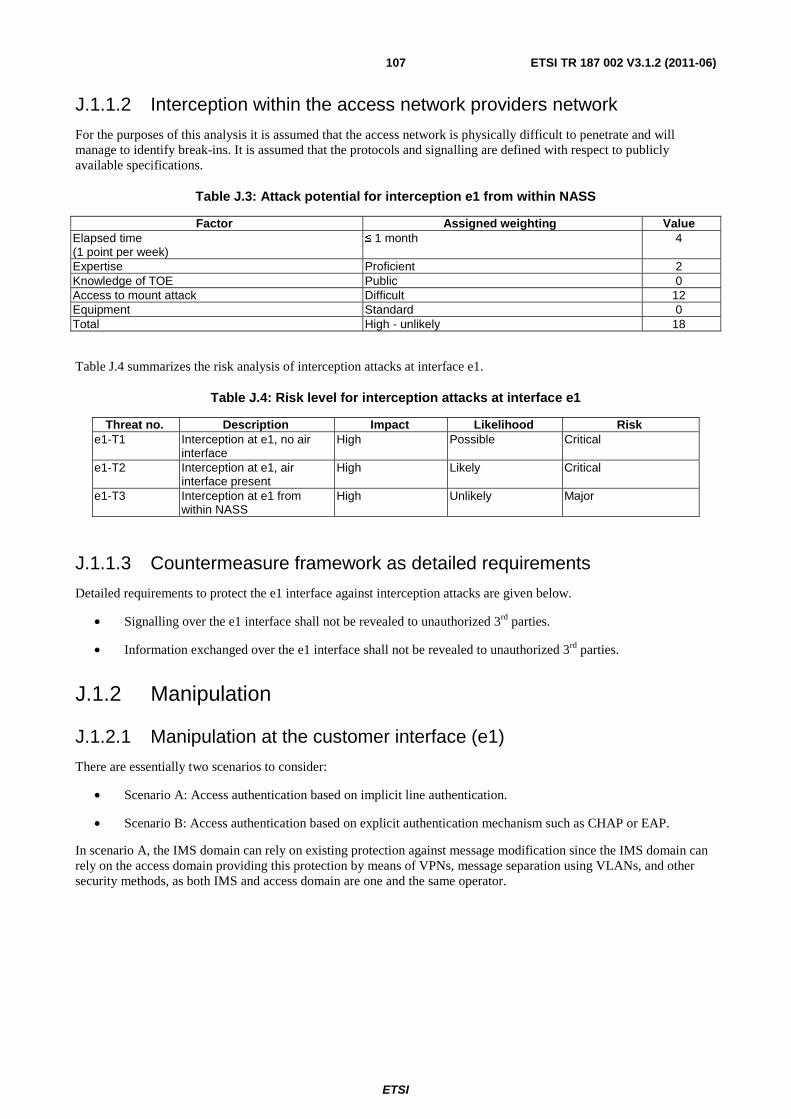
ETSI
ETSI TR 187 002 V3.1.2 (2011-06) 107
J.1.1.2 Interception within the access network providers network
For the purposes of this analysis it is assumed that the access network is physically difficult to penetrate and will manage to identify break-ins. It is assumed that the protocols and signalling are defined with respect to publicly available specifications.
Table J.3: Attack potential for interception e1 from within NASS
Factor Assigned weighting Value Elapsed time (1 point per week)
≤ 1 month 4
Expertise Proficient 2 Knowledge of TOE Public 0 Access to mount attack Difficult 12 Equipment Standard 0 Total High - unlikely 18
Table J.4 summarizes the risk analysis of interception attacks at interface e1.
Table J.4: Risk level for interception attacks at interface e1
Threat no. Description Impact Likelihood Risk e1-T1 Interception at e1, no air
interface High Possible Critical
e1-T2 Interception at e1, air interface present
High Likely Critical
e1-T3 Interception at e1 from within NASS
High Unlikely Major
J.1.1.3 Countermeasure framework as detailed requirements
Detailed requirements to protect the e1 interface against interception attacks are given below.
• Signalling over the e1 interface shall not be revealed to unauthorized 3rd parties.
• Information exchanged over the e1 interface shall not be revealed to unauthorized 3rd parties.
J.1.2 Manipulation
J.1.2.1 Manipulation at the customer interface (e1)
There are essentially two scenarios to consider:
• Scenario A: Access authentication based on implicit line authentication.
• Scenario B: Access authentication based on explicit authentication mechanism such as CHAP or EAP.
In scenario A, the IMS domain can rely on existing protection against message modification since the IMS domain can rely on the access domain providing this protection by means of VPNs, message separation using VLANs, and other security methods, as both IMS and access domain are one and the same operator.
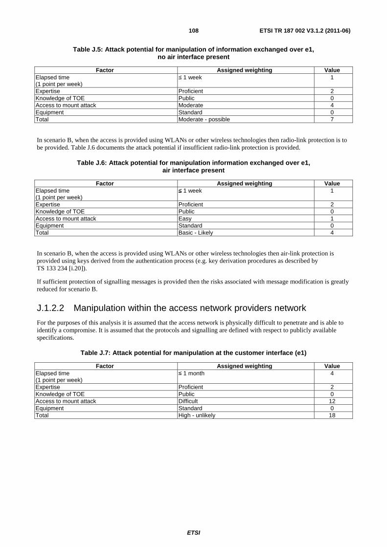
ETSI
ETSI TR 187 002 V3.1.2 (2011-06) 108
Table J.5: Attack potential for manipulation of information exchanged over e1, no air interface present
Factor Assigned weighting Value Elapsed time (1 point per week)
≤ 1 week 1
Expertise Proficient 2 Knowledge of TOE Public 0 Access to mount attack Moderate 4 Equipment Standard 0 Total Moderate - possible 7
In scenario B, when the access is provided using WLANs or other wireless technologies then radio-link protection is to be provided. Table J.6 documents the attack potential if insufficient radio-link protection is provided.
Table J.6: Attack potential for manipulation information exchanged over e1, air interface present
Factor Assigned weighting Value Elapsed time (1 point per week)
≤ 1 week 1
Expertise Proficient 2 Knowledge of TOE Public 0 Access to mount attack Easy 1 Equipment Standard 0 Total Basic - Likely 4
In scenario B, when the access is provided using WLANs or other wireless technologies then air-link protection is provided using keys derived from the authentication process (e.g. key derivation procedures as described by TS 133 234 [i.20]).
If sufficient protection of signalling messages is provided then the risks associated with message modification is greatly reduced for scenario B.
J.1.2.2 Manipulation within the access network providers network
For the purposes of this analysis it is assumed that the access network is physically difficult to penetrate and is able to identify a compromise. It is assumed that the protocols and signalling are defined with respect to publicly available specifications.
Table J.7: Attack potential for manipulation at the customer interface (e1)
Factor Assigned weighting Value Elapsed time (1 point per week)
≤ 1 month 4
Expertise Proficient 2 Knowledge of TOE Public 0 Access to mount attack Difficult 12 Equipment Standard 0 Total High - unlikely 18

ETSI
ETSI TR 187 002 V3.1.2 (2011-06) 109
Table J.8 summarizes the risk analysis of manipulation attacks towards interface e1.
Table J.8: Risk level for manipulation on information exchanged over interface e1
Threat no. Description Impact Likelihood Risk e1-T4 Manipulation of information
exchanged over e1, no air interface
High Possible Critical
e1-T5 Manipulation of information exchanged over e1, air interface present
High Likely Critical
e1-T6 Manipulation of information exchanged over e1 from within NASS
High Unlikely Major
J.1.2.3 Countermeasure framework as requirements
Detailed requirements to protect the e1 interface against manipulation attacks are given below.
• Signalling over the e1 interface shall be protected from change by unauthorized 3rd parties.
• Information exchanged over the e1 interface shall be protected from change by unauthorized 3rd parties.
J.1.3 IP Address and Identity spoofing Identity spoofing is a technique used to gain unauthorized access to networks and services, whereby the attacker sends messages to a computer with a forged identity indicating that the message is coming from a trusted host. Consider the following scenario where User B attaches to NASS and gets IP address IPB. Now the User B registers with the IMS using his IMS identity IDB with the P-CSCF using the NBA. The following three kinds of attacks are possible by spoofing the identities:
• Attacker A sends SIP messages using his own IMS identity (IDA) but with the source IP address of B (IPB):
- If the binding between the IP address (allocated by NASS during attachment) and the source IP address in subsequent packets is not checked, then the attacker will succeed. The consequence is that A pays for IMS service but IP connectivity is fraudulently charged to B. Note that this attack only makes sense for IMS services with outgoing traffic because the attacker will not receive any incoming packets addressed to the IMS identity that the attacker is impersonating.
• Attacker A sends SIP invite using his own source IP address (IPA) but with the IMS identity of B (IDB):
- If the binding between the IP address on the NASS level, and the public and private user identities is not checked then the attacker will succeed. The consequence will be that A pays for IP connectivity but IMS service is fraudulently charged to B.
• Attacker A sends SIP messages using IMS identity (IDB) and source IP address (IPB):
- If the bindings mentioned in the above attacks are not checked then the attacker will succeed, i.e. A fraudulently charges both IP connectivity and the IMS service to B. Note this attack only makes sense for IMS services with outgoing traffic because the attacker will not receive any incoming packets addressed to the IMS identity that he is impersonating.
• Denial of Service attacks aims at preventing authorized access or to reduce service levels. A DoS attack can be carried out by attacker A sending SIP BYE using the IP address IPB and the IMS identity (IDB) as described in the previous section. This attack assumes a successful IP address and identity spoofing.
J.1.3.1 Risk assessment
Table J.9 summarizes the attack potential of IP spoofing, and table J.10 summarizes the risk analysis of IP Spoofing attacks.
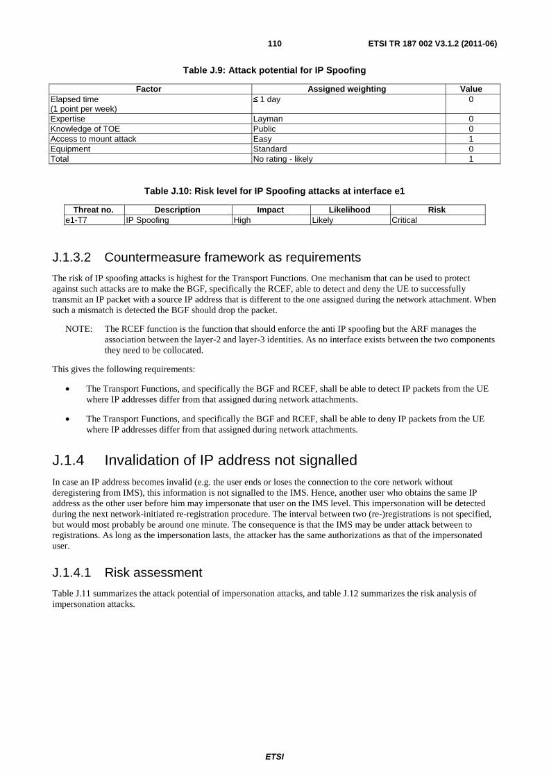
ETSI
ETSI TR 187 002 V3.1.2 (2011-06) 110
Table J.9: Attack potential for IP Spoofing
Factor Assigned weighting Value Elapsed time (1 point per week)
≤ 1 day 0
Expertise Layman 0 Knowledge of TOE Public 0 Access to mount attack Easy 1 Equipment Standard 0 Total No rating - likely 1
Table J.10: Risk level for IP Spoofing attacks at interface e1
Threat no. Description Impact Likelihood Risk e1-T7 IP Spoofing High Likely Critical
J.1.3.2 Countermeasure framework as requirements
The risk of IP spoofing attacks is highest for the Transport Functions. One mechanism that can be used to protect against such attacks are to make the BGF, specifically the RCEF, able to detect and deny the UE to successfully transmit an IP packet with a source IP address that is different to the one assigned during the network attachment. When such a mismatch is detected the BGF should drop the packet.
NOTE: The RCEF function is the function that should enforce the anti IP spoofing but the ARF manages the association between the layer-2 and layer-3 identities. As no interface exists between the two components they need to be collocated.
This gives the following requirements:
• The Transport Functions, and specifically the BGF and RCEF, shall be able to detect IP packets from the UE where IP addresses differ from that assigned during network attachments.
• The Transport Functions, and specifically the BGF and RCEF, shall be able to deny IP packets from the UE where IP addresses differ from that assigned during network attachments.
J.1.4 Invalidation of IP address not signalled In case an IP address becomes invalid (e.g. the user ends or loses the connection to the core network without deregistering from IMS), this information is not signalled to the IMS. Hence, another user who obtains the same IP address as the other user before him may impersonate that user on the IMS level. This impersonation will be detected during the next network-initiated re-registration procedure. The interval between two (re-)registrations is not specified, but would most probably be around one minute. The consequence is that the IMS may be under attack between to registrations. As long as the impersonation lasts, the attacker has the same authorizations as that of the impersonated user.
J.1.4.1 Risk assessment
Table J.11 summarizes the attack potential of impersonation attacks, and table J.12 summarizes the risk analysis of impersonation attacks.
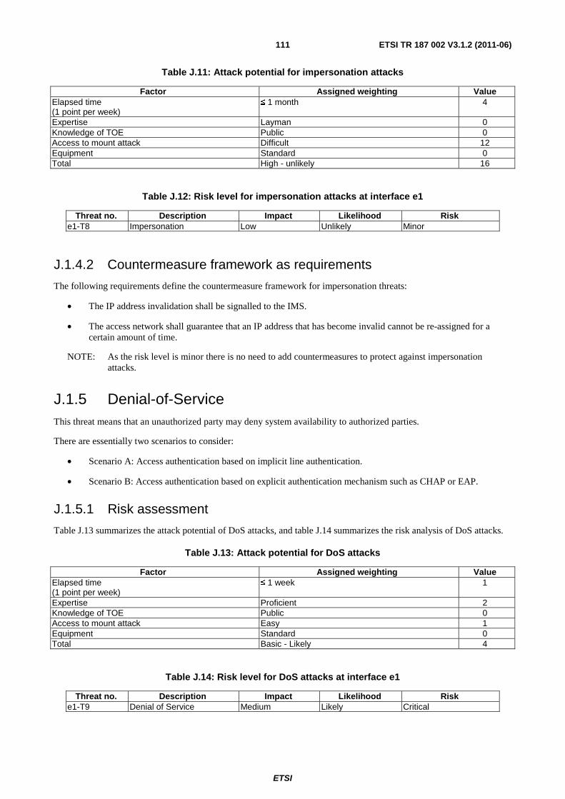
ETSI
ETSI TR 187 002 V3.1.2 (2011-06) 111
Table J.11: Attack potential for impersonation attacks
Factor Assigned weighting Value Elapsed time (1 point per week)
≤ 1 month 4
Expertise Layman 0 Knowledge of TOE Public 0 Access to mount attack Difficult 12 Equipment Standard 0 Total High - unlikely 16
Table J.12: Risk level for impersonation attacks at interface e1
Threat no. Description Impact Likelihood Risk e1-T8 Impersonation Low Unlikely Minor
J.1.4.2 Countermeasure framework as requirements
The following requirements define the countermeasure framework for impersonation threats:
• The IP address invalidation shall be signalled to the IMS.
• The access network shall guarantee that an IP address that has become invalid cannot be re-assigned for a certain amount of time.
NOTE: As the risk level is minor there is no need to add countermeasures to protect against impersonation attacks.
J.1.5 Denial-of-Service This threat means that an unauthorized party may deny system availability to authorized parties.
There are essentially two scenarios to consider:
• Scenario A: Access authentication based on implicit line authentication.
• Scenario B: Access authentication based on explicit authentication mechanism such as CHAP or EAP.
J.1.5.1 Risk assessment
Table J.13 summarizes the attack potential of DoS attacks, and table J.14 summarizes the risk analysis of DoS attacks.
Table J.13: Attack potential for DoS attacks
Factor Assigned weighting Value Elapsed time (1 point per week)
≤ 1 week 1
Expertise Proficient 2 Knowledge of TOE Public 0 Access to mount attack Easy 1 Equipment Standard 0 Total Basic - Likely 4
Table J.14: Risk level for DoS attacks at interface e1
Threat no. Description Impact Likelihood Risk e1-T9 Denial of Service Medium Likely Critical
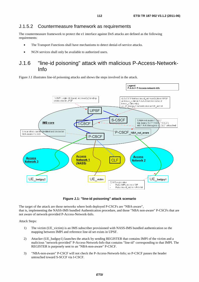
ETSI
ETSI TR 187 002 V3.1.2 (2011-06) 112
J.1.5.2 Countermeasure framework as requirements
The countermeasure framework to protect the e1 interface against DoS attacks are defined as the following requirements:
• The Transport Functions shall have mechanisms to detect denial-of-service attacks.
• NGN services shall only be available to authorized users.
J.1.6 "line-id poisoning" attack with malicious P-Access-Network-Info
Figure J.1 illustrates line-id poisoning attacks and shows the steps involved in the attack.
Figure J.1: "line-id poisoning" attack scenario
The target of the attack are those networks where both deployed P-CSCFs are "NBA-aware", that is, implementing the NASS-IMS bundled Authentication procedure, and those "NBA non-aware" P-CSCFs that are not aware of network-provided P-Access-Network-Info.
Attack Steps:
1) The victim (UE_victim) is an IMS subscriber provisioned with NASS-IMS bundled authentication so the mapping between IMPI and reference line-id set exists in UPSF.
2) Attacker (UE_badguy1) launches the attack by sending REGISTER that contains IMPI of the victim and a malicious "network-provided" P-Access-Network-Info that contains "line-id" corresponding to that IMPI. The REGISTER is purposely sent to an "NBA-non-aware" P-CSCF.
3) "NBA-non-aware" P-CSCF will not check the P-Access-Network-Info; so P-CSCF passes the header untouched toward S-SCCF via I-CSCF.
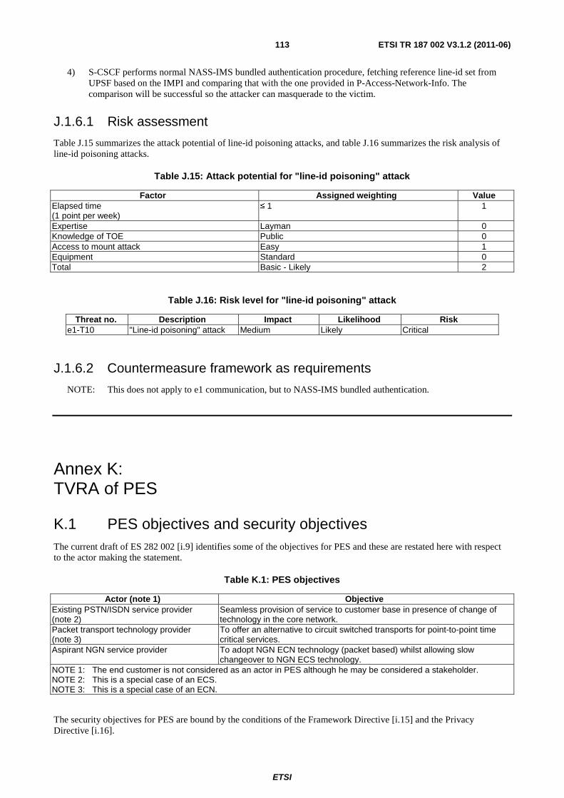
ETSI
ETSI TR 187 002 V3.1.2 (2011-06) 113
4) S-CSCF performs normal NASS-IMS bundled authentication procedure, fetching reference line-id set from UPSF based on the IMPI and comparing that with the one provided in P-Access-Network-Info. The comparison will be successful so the attacker can masquerade to the victim.
J.1.6.1 Risk assessment
Table J.15 summarizes the attack potential of line-id poisoning attacks, and table J.16 summarizes the risk analysis of line-id poisoning attacks.
Table J.15: Attack potential for "line-id poisoning" attack
Factor Assigned weighting Value Elapsed time (1 point per week)
≤ 1 1
Expertise Layman 0 Knowledge of TOE Public 0 Access to mount attack Easy 1 Equipment Standard 0 Total Basic - Likely 2
Table J.16: Risk level for "line-id poisoning" attack
Threat no. Description Impact Likelihood Risk e1-T10 "Line-id poisoning" attack Medium Likely Critical
J.1.6.2 Countermeasure framework as requirements
NOTE: This does not apply to e1 communication, but to NASS-IMS bundled authentication.
Annex K: TVRA of PES
K.1 PES objectives and security objectives The current draft of ES 282 002 [i.9] identifies some of the objectives for PES and these are restated here with respect to the actor making the statement.
Table K.1: PES objectives
Actor (note 1) Objective Existing PSTN/ISDN service provider (note 2)
Seamless provision of service to customer base in presence of change of technology in the core network.
Packet transport technology provider (note 3)
To offer an alternative to circuit switched transports for point-to-point time critical services.
Aspirant NGN service provider To adopt NGN ECN technology (packet based) whilst allowing slow changeover to NGN ECS technology.
NOTE 1: The end customer is not considered as an actor in PES although he may be considered a stakeholder. NOTE 2: This is a special case of an ECS. NOTE 3: This is a special case of an ECN.
The security objectives for PES are bound by the conditions of the Framework Directive [i.15] and the Privacy Directive [i.16].
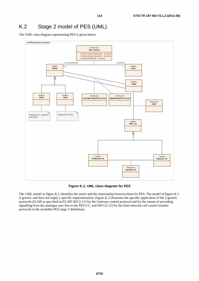
ETSI
ETSI TR 187 002 V3.1.2 (2011-06) 114
K.2 Stage 2 model of PES (UML) The UML class diagram representing PES is given below.
cd PES-analysis-structure
«asset»MGW
«asset»RGW
«asset»AGW
«asset»MGC
Deployed in customer premises
Deployed in ECN
«Protocol»GW_Control
~ AuthenticationCapabil ity: boolean~ ConfidentialityCapabil ity: boolean~ IntegrityCapabil ity: boolean
«asset»PES_CC
«asset»Outbound_CC
«asset»Inbound_CC
«Protocol»ISUP
«Protocol»InterNW_CC
«Protocol»AnalogueSignalProv ision
«asset»SGW
«Protocol»DigitalSignalProv ision
1
+Controls
0..*
+Is controlled by
Figure K.1: UML class diagram for PES
The UML model in figure K.1 identifies the assets and the relationship between them for PES. The model of figure K.1 is generic and does not imply a specific implementation. Figure K.2 illustrates the specific application of the 2 generic protocols (H.248 as specified in ES 283 002 [i.11] for the Gateway control protocol and for the means of providing signalling from the analogue user line to the PES-CC, and SIP-I [i.12] for the Inter-network call control transfer protocol) in the available PES stage 3 definitions.
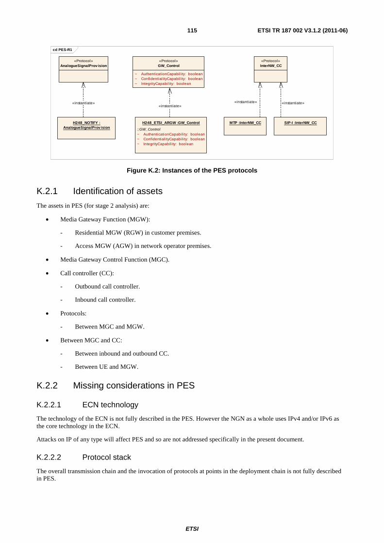
ETSI
ETSI TR 187 002 V3.1.2 (2011-06) 115
cd PES-R1
«Protocol»GW_Control
~ AuthenticationCapabil ity: boolean~ Confidential ityCapabil ity: boolean~ IntegrityCapabil ity: boolean
«Protocol»InterNW_CC
H248_ETSI_ARGW :GW_Control
::GW_Control~ AuthenticationCapabil ity: boolean~ Confidential ityCapabil ity: boolean~ IntegrityCapabil ity: boolean
SIP-I :InterNW_CCH248_NOTIFY :AnalogueSignalProv ision
«Protocol»AnalogueSignalProv ision
MTP :InterNW_CC
«instantiate»«instantiate»
«instantiate» «instantiate»
Figure K.2: Instances of the PES protocols
K.2.1 Identification of assets
The assets in PES (for stage 2 analysis) are:
• Media Gateway Function (MGW):
- Residential MGW (RGW) in customer premises.
- Access MGW (AGW) in network operator premises.
• Media Gateway Control Function (MGC).
• Call controller (CC):
- Outbound call controller.
- Inbound call controller.
• Protocols:
- Between MGC and MGW.
• Between MGC and CC:
- Between inbound and outbound CC.
- Between UE and MGW.
K.2.2 Missing considerations in PES
K.2.2.1 ECN technology
The technology of the ECN is not fully described in the PES. However the NGN as a whole uses IPv4 and/or IPv6 as the core technology in the ECN.
Attacks on IP of any type will affect PES and so are not addressed specifically in the present document.
K.2.2.2 Protocol stack
The overall transmission chain and the invocation of protocols at points in the deployment chain is not fully described in PES.
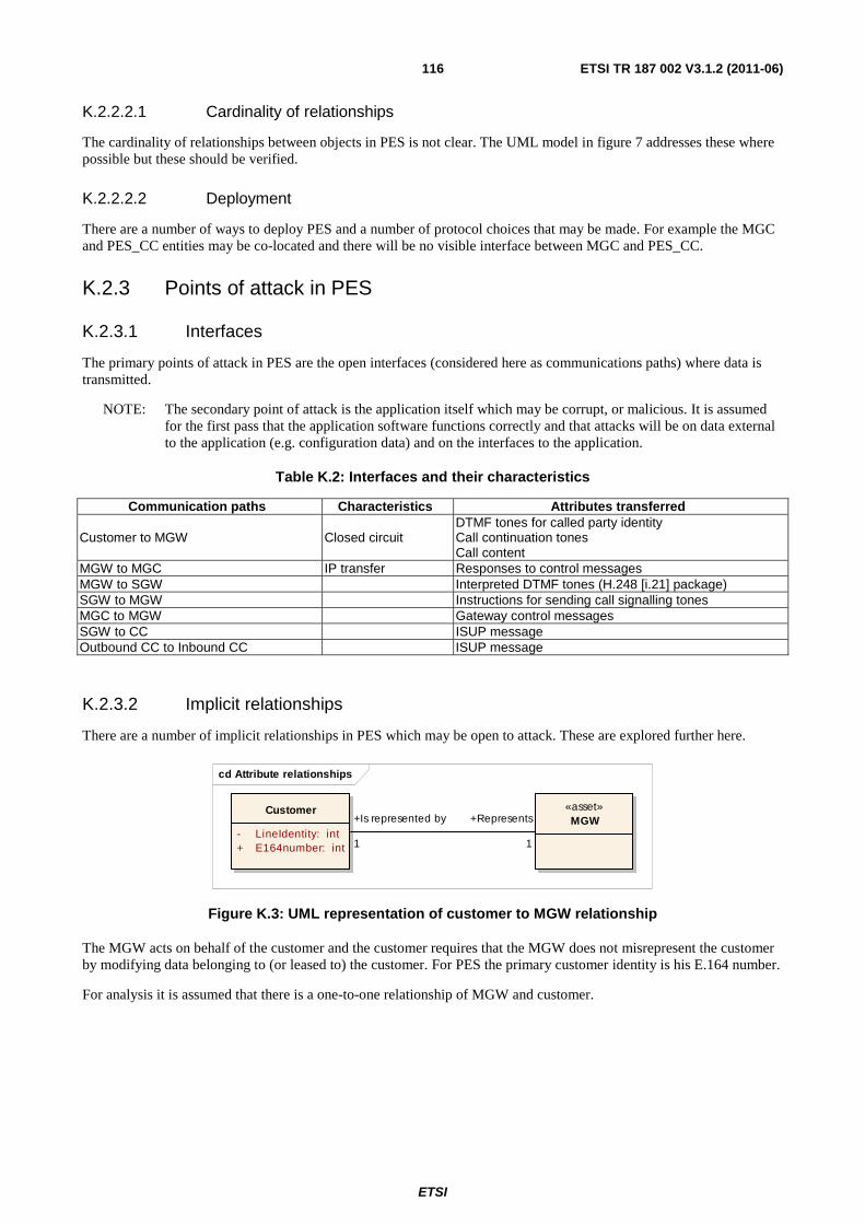
ETSI
ETSI TR 187 002 V3.1.2 (2011-06) 116
K.2.2.2.1 Cardinality of relationships
The cardinality of relationships between objects in PES is not clear. The UML model in figure 7 addresses these where possible but these should be verified.
K.2.2.2.2 Deployment
There are a number of ways to deploy PES and a number of protocol choices that may be made. For example the MGC and PES_CC entities may be co-located and there will be no visible interface between MGC and PES_CC.
K.2.3 Points of attack in PES
K.2.3.1 Interfaces
The primary points of attack in PES are the open interfaces (considered here as communications paths) where data is transmitted.
NOTE: The secondary point of attack is the application itself which may be corrupt, or malicious. It is assumed for the first pass that the application software functions correctly and that attacks will be on data external to the application (e.g. configuration data) and on the interfaces to the application.
Table K.2: Interfaces and their characteristics
Communication paths Characteristics Attributes transferred
Customer to MGW Closed circuit DTMF tones for called party identity Call continuation tones Call content
MGW to MGC IP transfer Responses to control messages MGW to SGW Interpreted DTMF tones (H.248 [i.21] package) SGW to MGW Instructions for sending call signalling tones MGC to MGW Gateway control messages SGW to CC ISUP message Outbound CC to Inbound CC ISUP message
K.2.3.2 Implicit relationships
There are a number of implicit relationships in PES which may be open to attack. These are explored further here.
cd Attribute relationships
«asset»MGW
Customer
- LineIdentity: int+ E164number: int 1
+Is represented by
1
+Represents
Figure K.3: UML representation of customer to MGW relationship
The MGW acts on behalf of the customer and the customer requires that the MGW does not misrepresent the customer by modifying data belonging to (or leased to) the customer. For PES the primary customer identity is his E.164 number.
For analysis it is assumed that there is a one-to-one relationship of MGW and customer.
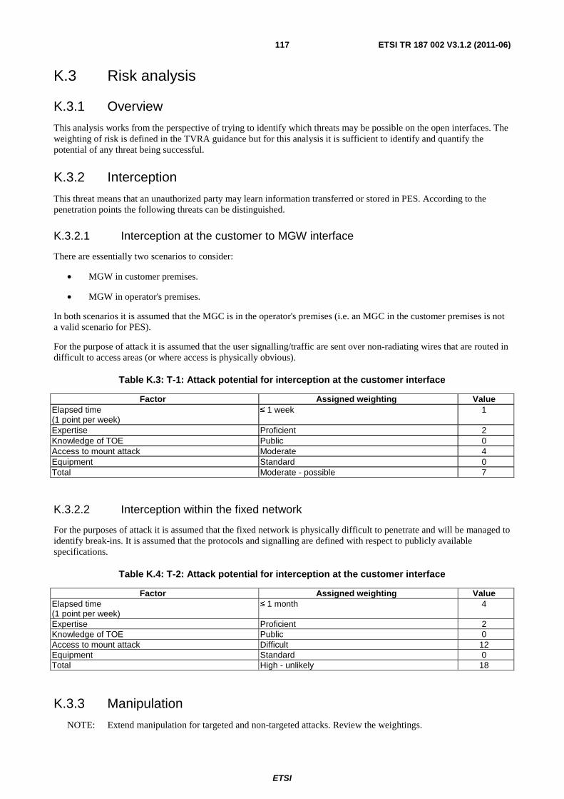
ETSI
ETSI TR 187 002 V3.1.2 (2011-06) 117
K.3 Risk analysis
K.3.1 Overview
This analysis works from the perspective of trying to identify which threats may be possible on the open interfaces. The weighting of risk is defined in the TVRA guidance but for this analysis it is sufficient to identify and quantify the potential of any threat being successful.
K.3.2 Interception
This threat means that an unauthorized party may learn information transferred or stored in PES. According to the penetration points the following threats can be distinguished.
K.3.2.1 Interception at the customer to MGW interface
There are essentially two scenarios to consider:
• MGW in customer premises.
• MGW in operator's premises.
In both scenarios it is assumed that the MGC is in the operator's premises (i.e. an MGC in the customer premises is not a valid scenario for PES).
For the purpose of attack it is assumed that the user signalling/traffic are sent over non-radiating wires that are routed in difficult to access areas (or where access is physically obvious).
Table K.3: T-1: Attack potential for interception at the customer interface
Factor Assigned weighting Value Elapsed time (1 point per week)
≤ 1 week 1
Expertise Proficient 2 Knowledge of TOE Public 0 Access to mount attack Moderate 4 Equipment Standard 0 Total Moderate - possible 7
K.3.2.2 Interception within the fixed network
For the purposes of attack it is assumed that the fixed network is physically difficult to penetrate and will be managed to identify break-ins. It is assumed that the protocols and signalling are defined with respect to publicly available specifications.
Table K.4: T-2: Attack potential for interception at the customer interface
Factor Assigned weighting Value Elapsed time (1 point per week)
≤ 1 month 4
Expertise Proficient 2 Knowledge of TOE Public 0 Access to mount attack Difficult 12 Equipment Standard 0 Total High - unlikely 18
K.3.3 Manipulation
NOTE: Extend manipulation for targeted and non-targeted attacks. Review the weightings.

ETSI
ETSI TR 187 002 V3.1.2 (2011-06) 118
K.3.3.1 Manipulation at the customer interface
There are essentially two scenarios to consider:
• MGW in customer premises.
• MGW in operator's premises.
In both scenarios it is assumed that the MGC is in the operator's premises (i.e. an MGC in the customer premises is not a valid scenario for PES).
For the purpose of attack it is assumed that the user signalling/traffic are sent over non-radiating wires that are routed in difficult to access areas (or where access is physically obvious).
Table K.5: T-3: Attack potential for manipulation at the customer interface
Factor Assigned weighting Value Elapsed time (1 point per week)
≤ 1 week 1
Expertise Proficient 2 Knowledge of TOE Public 0 Access to mount attack Moderate 4 Equipment Standard 0 Total Moderate - possible 7
K.3.3.1.1 Manipulation in the fixed parts of the network
In contrast to the customer interface in the fixed parts of the network all kinds of manipulation are possible:
• deletion;
• reordering; and
• insertion of data is possible without restriction.
The underlying attacks can be in principle at least the same as for manipulation at the radio interface, with the following attacks added.
• Manipulations can be done in the following ways:
- an attacker can use some equipment infiltrated into any interface of the system to manipulate the data and voice signals being transferred there;
- deletion can be carried out, e.g. by physical action like wire-cutting, but also by rerouting of the data (e.g. by manipulation of the data header);
- an attacker, who has access to an entity in the system, e.g. the MGC/SGW, can manipulate the data or voice signals being processed or stored.
Table K.6: T-4: Attack potential for manipulation in the fixed network
Factor Assigned weighting Value Elapsed time (1 point per week)
≤ 1 month 4
Expertise Proficient 2 Knowledge of TOE Public 0 Access to mount attack Moderate 4 Equipment Specialized 3 Total Moderate - possible 13
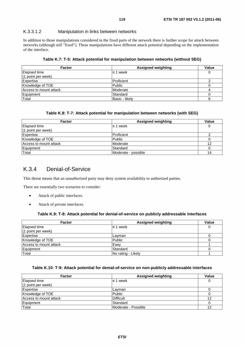
ETSI
ETSI TR 187 002 V3.1.2 (2011-06) 119
K.3.3.1.2 Manipulation in links between networks
In addition to those manipulations considered in the fixed parts of the network there is further scope for attack between networks (although still "fixed"). These manipulations have different attack potential depending on the implementation of the interface.
Table K.7: T-5: Attack potential for manipulation between networks (without SEG)
Factor Assigned weighting Value Elapsed time (1 point per week)
≤ 1 week 0
Expertise Proficient 2 Knowledge of TOE Public 0 Access to mount attack Moderate 4 Equipment Standard 0 Total Basic - likely 6
Table K.8: T-7: Attack potential for manipulation between networks (with SEG)
Factor Assigned weighting Value Elapsed time (1 point per week)
≤ 1 week 0
Expertise Proficient 2 Knowledge of TOE Public 0 Access to mount attack Moderate 12 Equipment Standard 0 Total Moderate - possible 14
K.3.4 Denial-of-Service
This threat means that an unauthorized party may deny system availability to authorized parties.
There are essentially two scenarios to consider:
• Attack of public interfaces.
• Attack of private interfaces.
Table K.9: T-8: Attack potential for denial-of-service on publicly addressable interfaces
Factor Assigned weighting Value Elapsed time (1 point per week)
≤ 1 week 0
Expertise Layman 0 Knowledge of TOE Public 0 Access to mount attack Easy 1 Equipment Standard 0 Total No rating - Likely 1
Table K.10: T-9: Attack potential for denial-of-service on non-publicly addressable interfaces
Factor Assigned weighting Value Elapsed time (1 point per week)
≤ 1 week 0
Expertise Layman 0 Knowledge of TOE Public 0 Access to mount attack Difficult 12 Equipment Standard 0 Total Moderate - Possible 12
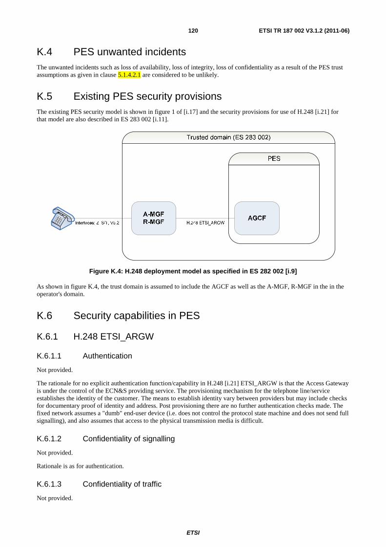
ETSI
ETSI TR 187 002 V3.1.2 (2011-06) 120
K.4 PES unwanted incidents The unwanted incidents such as loss of availability, loss of integrity, loss of confidentiality as a result of the PES trust assumptions as given in clause 5.1.4.2.1 are considered to be unlikely.
K.5 Existing PES security provisions The existing PES security model is shown in figure 1 of [i.17] and the security provisions for use of H.248 [i.21] for that model are also described in ES 283 002 [i.11].
Figure K.4: H.248 deployment model as specified in ES 282 002 [i.9]
As shown in figure K.4, the trust domain is assumed to include the AGCF as well as the A-MGF, R-MGF in the in the operator's domain.
K.6 Security capabilities in PES
K.6.1 H.248 ETSI_ARGW
K.6.1.1 Authentication
Not provided.
The rationale for no explicit authentication function/capability in H.248 [i.21] ETSI_ARGW is that the Access Gateway is under the control of the ECN&S providing service. The provisioning mechanism for the telephone line/service establishes the identity of the customer. The means to establish identity vary between providers but may include checks for documentary proof of identity and address. Post provisioning there are no further authentication checks made. The fixed network assumes a "dumb" end-user device (i.e. does not control the protocol state machine and does not send full signalling), and also assumes that access to the physical transmission media is difficult.
K.6.1.2 Confidentiality of signalling
Not provided.
Rationale is as for authentication.
K.6.1.3 Confidentiality of traffic
Not provided.
ETSI
ETSI TR 187 002 V3.1.2 (2011-06) 121
Rationale is as for authentication.
K.6.1.4 Integrity of signalling
Not provided.
Rationale is as for authentication.
K.6.1.5 Integrity of traffic
Not provided.
Rationale is as for authentication.
K.7 Role of NGN subsystems in PES
K.7.1 Transport plane
K.7.1.1 NASS
No explicit role in PES.
K.7.1.2 RACS
The RACS lies on the interface between the service plane and the transport plane. RACS is used in PES to ensure that the IP network provides appropriate RTP streams for the carriage of 64k-TDM traffic.
K.7.1.3 Transport elements
No role defined for PES in NGN-R1.
K.7.2 Service plane
K.7.2.1 IMS
No role defined for PES in NGN-R1.
K.7.2.2 PSS
No role defined for PES in NGN-R1.
K.7.3 Recommendations
The role of the transport network and means to secure it need to be addressed. It is recognized that the Security Gateway (SEG) functions described in TS 133 203 [i.19] can be deployed to protect the signalling links (using IPsec ESP in Tunnel Mode). It is noted that the SEG as currently defined does not protect media but work is underway to address this in 3GPP.
There is a risk to availability not addressed by TS 133 203 [i.19] if the addresses of the point of interconnection are in the public domain. The denial of service attacks are more difficult to mitigate against and work has to be done in this area. In particular the use of public address space at the point of interconnect should be avoided.
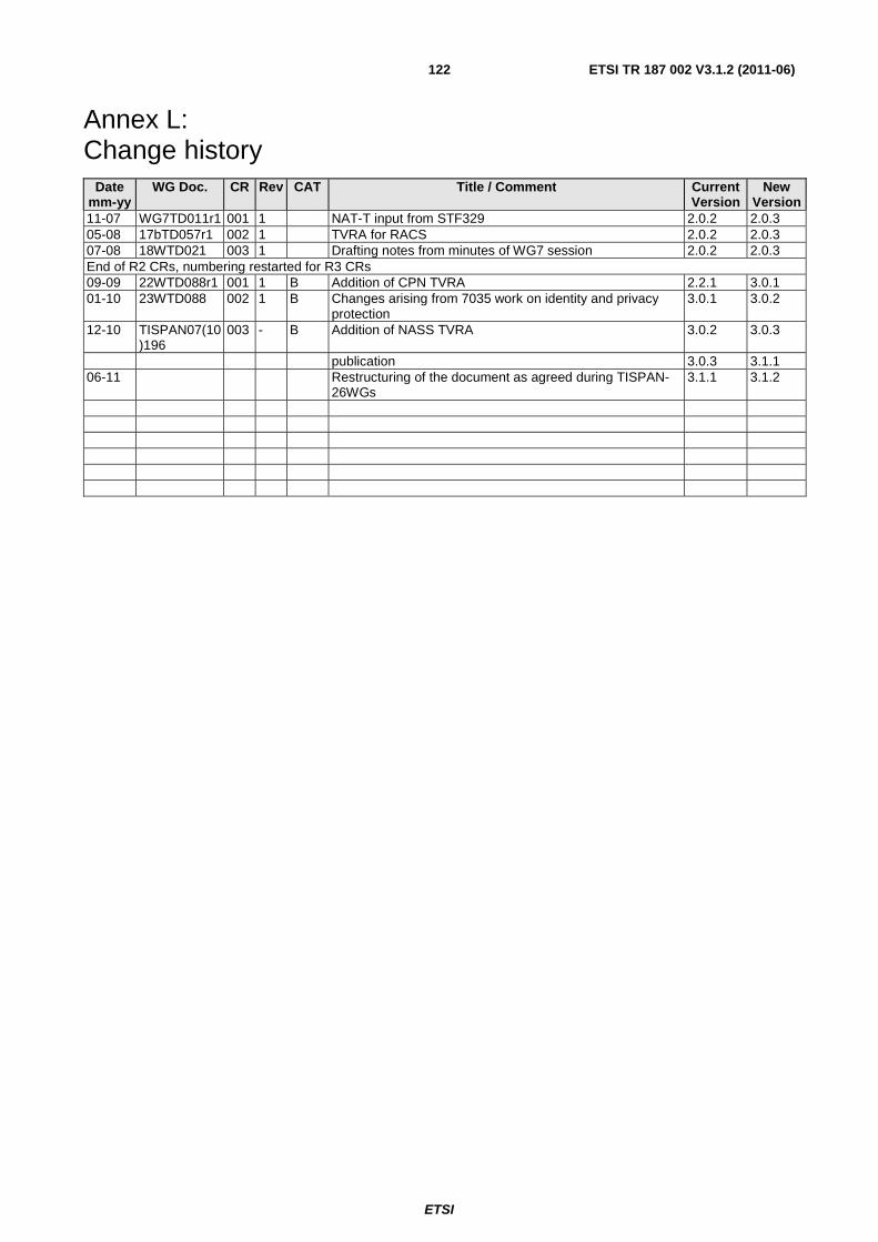
ETSI
ETSI TR 187 002 V3.1.2 (2011-06) 122
Annex L: Change history
Date mm-yy
WG Doc. CR Rev CAT Title / Comment Current Version
New Version
11-07 WG7TD011r1 001 1 NAT-T input from STF329 2.0.2 2.0.3 05-08 17bTD057r1 002 1 TVRA for RACS 2.0.2 2.0.3 07-08 18WTD021 003 1 Drafting notes from minutes of WG7 session 2.0.2 2.0.3 End of R2 CRs, numbering restarted for R3 CRs 09-09 22WTD088r1 001 1 B Addition of CPN TVRA 2.2.1 3.0.1 01-10 23WTD088 002 1 B Changes arising from 7035 work on identity and privacy
protection 3.0.1 3.0.2
12-10 TISPAN07(10)196
003 - B Addition of NASS TVRA 3.0.2 3.0.3
publication 3.0.3 3.1.1 06-11 Restructuring of the document as agreed during TISPAN-
26WGs 3.1.1 3.1.2

ETSI
ETSI TR 187 002 V3.1.2 (2011-06) 123
Annex M: Bibliography ETSI ES 282 007: "Telecommunications and Internet converged Services and Protocols for Advanced Networking (TISPAN); IP Multimedia Subsystem (IMS); Functional architecture".

ETSI
ETSI TR 187 002 V3.1.2 (2011-06) 124
History
Document history
V1.1.1 March 2006 Publication
V1.2.2 March 2008 Publication
V2.1.1 December 2008 Publication
V3.1.1 April 2011 Publication
V3.1.2 June 2011 Restructuring as agreed in TISPAN#26