Embed Size (px)
Citation preview

Operating instructions
50118386
ETX ac 125/150
G
01.01-
05.03

0108
.GB
ForewordThe present ORIGINAL OPERATING INSTRUCTIONS are designed to providesufficient instruction for the safe operation of the industrial truck. The information isprovided clearly and concisely. The chapters are arranged by letter. Each chapterstarts with page 1. The page identification consists of a chapter letter and a pagenumber.For example: Page B 2 is the second page in chapter B.
The operating instructions detail different truck models. When operating and servicingthe truck, make sure that the instructions apply to your truck model.
Safety instructions and important explanations are indicated by the followinggraphics:
f Used before safety instructions which must be observed to avoid danger topersonnel.
m Used before notices which must be observed to avoid material damage.
A Used before notices and explanations.
t Used to indicate standard equipment.
o Used to indicate optional equipment.
Our trucks are subject to ongoing development. Jungheinrich reserves the right toalter the design, equipment and technical features of the truck. No guarantee ofparticular features of the truck should therefore be inferred from the present operatinginstructions.
Copyright
Copyright of these operating instructions remains with JUNGHEINRICH AG.
Jungheinrich Aktiengesellschaft
Am Stadtrand 3522047 Hamburg - GERMANY
Telephone: +49 (0) 40/6948-0
www.jungheinrich.com

0108
.GB
0108
.GB

I 1
5011
8386
GB
Table of ContentsA Correct use and application of the truck
B Truck description
1 Application description ..................................................................... B 12 Description of assembly groups and functions ................................. B 22.1 Truck ................................................................................................ B 43 Technical data - standard version .................................................... B 63.1 Performance data ............................................................................. B 63.2 Dimensions ...................................................................................... B 83.3 Wheels ............................................................................................. B 83.4 EN standards ................................................................................... B 93.5 Conditions of use ............................................................................. B 94 Label positions and identification plates ......................................... B 104.1 Truck identification plate ................................................................ B 114.2 Capacity ......................................................................................... B 11
C Transportation and commissioning
1 Transport .......................................................................................... C 12 Transportation by crane ................................................................... C 13 Commissioning ................................................................................. C 23.1 Commissioning without battery ........................................................ C 24 Initial operation ................................................................................. C 3
D Battery - Servicing, recharging, replacement
1 Safety regulations governing the handling of lead-acid batteries ..... D 12 Battery types .................................................................................... D 23 Charging the battery ......................................................................... D 24 Removing and installing the battery ................................................. D 34.1 Removal and replacement with battery trolley ................................. D 35 Check battery condition, acid level, and acid concentration ............ D 46 Battery discharge indicator ............................................................... D 4

5011
8386
GB
I 2
E Operation
1 Safety regulations governing the operation of the fork lift truck ....... E 12 Description of Operating and Display Elements ............................... E 22.1 Operating and display elements at the control panel ....................... E 22.2 Foot-operated elements ................................................................... E 32.3 Operating and display elements at the display ............................... E 43 Starting up the truck ....................................................................... E 173.1 Reference drive .............................................................................. E 173.2 Checks and operations to be performed before starting daily work E 183.3 Mounting and descending from the truck ....................................... E 183.4 Adjusting the driver seat ................................................................. E 193.5 Safety restraint belt ........................................................................ E 203.6 Adjusting the operating panel ......................................................... E 223.7 Providing operational readiness ..................................................... E 223.8 Driver position adjustment .............................................................. E 224 Operation of the truck ..................................................................... E 234.1 Safety regulations applicable when operating the truck ................. E 234.2 Driving, steering, braking ............................................................... E 254.3 Lifting - lowering - traversing - swivelling ....................................... E 304.4 Picking up, transporting, and putting down load units .................... E 334.5 Lifting height preselection .............................................................. E 364.6 Laser beam rack shelf indicator ..................................................... E 384.7 Safe parking of the truck ................................................................ E 385 Troubleshooting ............................................................................. E 396 Monitoring function and safety devices .......................................... E 406.1 Emergency stop facility .................................................................. E 406.2 Drive cut-off with override (o) ....................................................... E 406.3 Lift cut-off with override (o) ........................................................... E 406.4 End of aisle safety device (o) ....................................................... E 416.5 Automatic EMERGENCY STOP .................................................... E 426.6 Recovering the truck from a narrow aisle ....................................... E 42
I 3
5011
8386
GB
F Maintenance of the fork lift truck
1 Operational safety and environmental protection ..............................F 12 Safety regulations applicable to truck maintenance ..........................F 13 Servicing and inspection ...................................................................F 33.1 Maintenance checklist ETX ac 125/150 .............................................F 44 Lubrication schedule .........................................................................F 75 Fuels, coolants and lubricants ...........................................................F 96 Description of servicing and maintenance operations .....................F 106.1 Prepare the truck for the servicing and maintenance operations ....F 106.2 Secure the load-carrying unit ..........................................................F 106.3 Cleaning the lifting chains ...............................................................F 106.4 Inspection of lifting chains ...............................................................F 116.5 Chain repair .....................................................................................F 116.6 Changing gear oil ............................................................................F 116.7 Cleaning the aeration filter ..............................................................F 126.8 Changing the hydraulic filter ............................................................F 126.9 Hydraulic oil .....................................................................................F 136.10 Checking the brake fluid ..................................................................F 146.11 Restrain safety belt service .............................................................F 146.12 Electrical fuses ................................................................................F 146.13 Recommissioning the truck .............................................................F 157 Decommissioning the fork lift truck .................................................F 157.1 Operations to be performed prior to decommissioning ...................F 157.2 Measures to be taken during decommissioning ..............................F 157.3 Recommissioning the truck .............................................................F 168 Safety checks to be performed at regular intervals and following
any untoward incidents (D: Accident prevention check according to VBG 36) ......................................................................F 16

5011
8386
GB
I 4
5011
8386
GB
I 4

A 1
5011
8386
GB
A Correct use and application of the truck
A The “Guidelines for the Correct Use and Application of Industrial Trucks” (VDMA) areincluded in the scope of delivery for this truck. The guidelines are part of these oper-ating instructions and must always be heeded. National regulations are fully applica-ble.
This electric three-way lift truck has been constructed for tiering and untiering of pal-letised goods in racking systems with narrow aisles designed for this purpose left andright of the travel direction.It must be used, operated and maintained according to the information in these oper-ating instructions. Any other uses are outside the design envelope and can lead toinjury to persons or damage to equipment and property. The max. admissible load tobe picked up is indicated on the identification plate and load diagram label affixed tothe truck.
Improper use: The truck must not be used for towing or pushing loads. Above all, itis prohibited to overload the truck by too heavy or unbalanced loads.
Duties of the user: A “user” within the meaning of these operating instructions is de-fined as any natural or legal person who either uses the fork lift truck himself, or onwhose behalf it is used. In special cases (e.g. leasing or renting), the user is consid-ered the person, who, in accordance with existing contractual agreements betweenthe owner and the user of the fork lift truck, is charged with the observance of the op-erating duties.The user must ensure that the truck is not abused and only used within its design lim-its and that all danger to life and limb of the operator, or third parties, is avoided. Inaddition to this, it must be ensured that the relevant accident prevention regulationsand other safety-related provisions, as well as the operating, servicing and mainte-nance guidelines, are observed. The user must also ensure that all persons operatingthe truck have read and understood these operating instructions.
m If these operating instructions are not observed the warranty becomes void. Thesame applies if improper works are carried out at the device by the customer and/orthird parties without permission of our Customer Service.
Mounting of attachments: The mounting or installation of any attachments whichwill interfere with, or supplement, the functions of the truck is permitted only after writ-ten approval by the manufacturer has been obtained. If necessary, the approval oflocal authorities has to be obtained.Any approval obtained from local authorities does not, however, make the approvalby the manufacturer unnecessary.
Modification of the truck: It is not allowed to modify or retrofit the truck without priorpermission of the manufacturer. Modifications that affect the stability, safety, and car-rying capacity of the truck are prohibited.

A 2
5011
8386
GB
A 2
5011
8386
GB

B 1
5011
8386
GB
B Truck description1 Application description
The ETX ac 125/150 is an electric three-way lift truck which picks up, transports, andlifts its load outside the wheelbase. It can be used for internal goods traffic to stackand transport DIN 15142 pallets, DIN 15144 lattice box pallet, and other palletisedloads. If the ETX ac 125/150 is used for assembly works with an according workingplatform, the load carrying-unit must be supplied or approved by the manufacturer.For optimisation of the turnaround performance the truck can be operated diagonally,i. e. that travelling and lifting is possible simultaneously.
As standard, swivel/traverse forks or telescopic forks can be used as load-carryingunits. The load fork can be designed for different load units. In case of the swivel/traverse fork the distance between the fork arms is adjustable.
For operation in narrow aisles the ETX ac 125/150 can be either be equipped with arail guidance system (RG) or inductive guidance system (IF). The driver can fullyconcentrate on his stacking work. Simultaneous travel and lifting is enables in narrowaisles. The activation is triggered by aisle detection sensors. Outside narrow aislesthe ETX ac 125/150 can be freely moved, partly at restricted travel speeds dependingon certain lifting heights.
The racking systems must be constructed for the ETX ac 125/150. The safetydistances required and prescribed by the manufacturer (e. g. prEN 1726-2 item 7.3.2)must be strictly observed. The ground must comply with DIN 15185. For the railguidance system (RG) the narrow aisles must be equipped with guide rails. Vulkollan guide rollers screwed to the truck chassis guide the truck between the guiderails.For the inductive guidance system (IF) a guide wire must be installed in the ground,and the signals from the guide wires are received by sensors at the truck chassis andprocessed in the truck computer.
Definition of the travel direction
The following definitions are made for the indication of the travel direction:
left
right
drivedirection
loaddirection

B 2
5011
8386
GB
2 Description of assembly groups and functions
1
2
3
4
5
6
7
9
101112
8
17
16
15
14
13
B 2
5011
8386
GB
2 Description of assembly groups and functions
1
2
3
4
5
6
7
9
101112
8
17
16
15
14
13

B 3
5011
8386
GB
Item Designation1 t Lifting mast2 t Load chains3 t Lifting cylinder4 t Signal and supply lines5 t Lateral traversing frame6 t Boom7 t Fork arm carriage8 o Storage location sensor9 o Load sensor
10 o IG sensors (only for inductive guidance)11 t Load wheel12 o Guide rollers (only for rail guidance)13 t Traction compartment14 t Battery compartment15 t Driver seat16 t Overhead guard17 o Working lights
t = Series equipment o = Optional equipment
B 4
5011
8386
GB
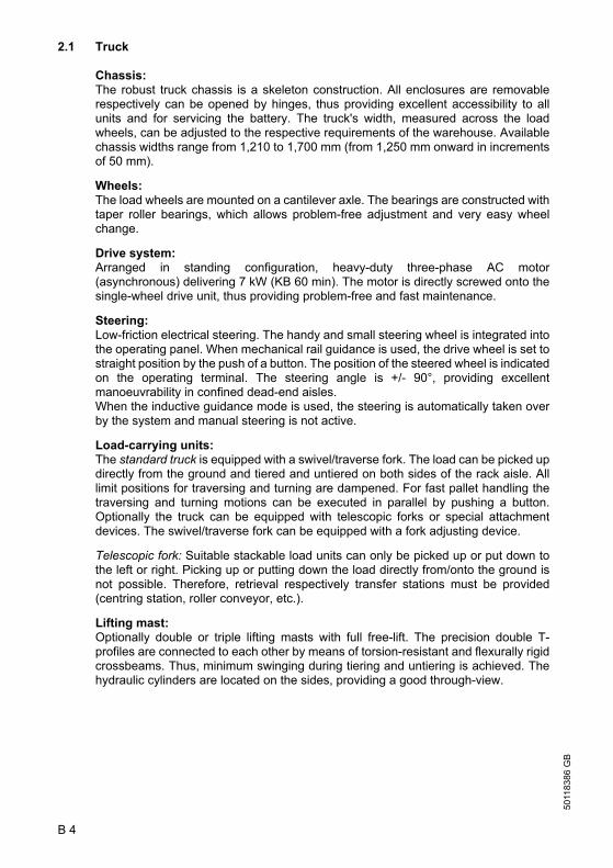
2.1 Truck
Chassis:The robust truck chassis is a skeleton construction. All enclosures are removablerespectively can be opened by hinges, thus providing excellent accessibility to allunits and for servicing the battery. The truck's width, measured across the loadwheels, can be adjusted to the respective requirements of the warehouse. Availablechassis widths range from 1,210 to 1,700 mm (from 1,250 mm onward in incrementsof 50 mm).
Wheels: The load wheels are mounted on a cantilever axle. The bearings are constructed withtaper roller bearings, which allows problem-free adjustment and very easy wheelchange.
Drive system:Arranged in standing configuration, heavy-duty three-phase AC motor(asynchronous) delivering 7 kW (KB 60 min). The motor is directly screwed onto thesingle-wheel drive unit, thus providing problem-free and fast maintenance.
Steering:Low-friction electrical steering. The handy and small steering wheel is integrated intothe operating panel. When mechanical rail guidance is used, the drive wheel is set tostraight position by the push of a button. The position of the steered wheel is indicatedon the operating terminal. The steering angle is +/- 90°, providing excellentmanoeuvrability in confined dead-end aisles.When the inductive guidance mode is used, the steering is automatically taken overby the system and manual steering is not active.
Load-carrying units:The standard truck is equipped with a swivel/traverse fork. The load can be picked updirectly from the ground and tiered and untiered on both sides of the rack aisle. Alllimit positions for traversing and turning are dampened. For fast pallet handling thetraversing and turning motions can be executed in parallel by pushing a button.Optionally the truck can be equipped with telescopic forks or special attachmentdevices. The swivel/traverse fork can be equipped with a fork adjusting device.
Telescopic fork: Suitable stackable load units can only be picked up or put down tothe left or right. Picking up or putting down the load directly from/onto the ground isnot possible. Therefore, retrieval respectively transfer stations must be provided(centring station, roller conveyor, etc.).
Lifting mast:Optionally double or triple lifting masts with full free-lift. The precision double T-profiles are connected to each other by means of torsion-resistant and flexurally rigidcrossbeams. Thus, minimum swinging during tiering and untiering is achieved. Thehydraulic cylinders are located on the sides, providing a good through-view.
B 4
5011
8386
GB
2.1 Truck
Chassis:The robust truck chassis is a skeleton construction. All enclosures are removablerespectively can be opened by hinges, thus providing excellent accessibility to allunits and for servicing the battery. The truck's width, measured across the loadwheels, can be adjusted to the respective requirements of the warehouse. Availablechassis widths range from 1,210 to 1,700 mm (from 1,250 mm onward in incrementsof 50 mm).
Wheels: The load wheels are mounted on a cantilever axle. The bearings are constructed withtaper roller bearings, which allows problem-free adjustment and very easy wheelchange.
Drive system:Arranged in standing configuration, heavy-duty three-phase AC motor(asynchronous) delivering 7 kW (KB 60 min). The motor is directly screwed onto thesingle-wheel drive unit, thus providing problem-free and fast maintenance.
Steering:Low-friction electrical steering. The handy and small steering wheel is integrated intothe operating panel. When mechanical rail guidance is used, the drive wheel is set tostraight position by the push of a button. The position of the steered wheel is indicatedon the operating terminal. The steering angle is +/- 90°, providing excellentmanoeuvrability in confined dead-end aisles.When the inductive guidance mode is used, the steering is automatically taken overby the system and manual steering is not active.
Load-carrying units:The standard truck is equipped with a swivel/traverse fork. The load can be picked updirectly from the ground and tiered and untiered on both sides of the rack aisle. Alllimit positions for traversing and turning are dampened. For fast pallet handling thetraversing and turning motions can be executed in parallel by pushing a button.Optionally the truck can be equipped with telescopic forks or special attachmentdevices. The swivel/traverse fork can be equipped with a fork adjusting device.
Telescopic fork: Suitable stackable load units can only be picked up or put down tothe left or right. Picking up or putting down the load directly from/onto the ground isnot possible. Therefore, retrieval respectively transfer stations must be provided(centring station, roller conveyor, etc.).
Lifting mast:Optionally double or triple lifting masts with full free-lift. The precision double T-profiles are connected to each other by means of torsion-resistant and flexurally rigidcrossbeams. Thus, minimum swinging during tiering and untiering is achieved. Thehydraulic cylinders are located on the sides, providing a good through-view.

B 5
5011
8386
GB
Driver position:The spacious, ergonomically designed driver position with comfort seat and theergonomically optimised arrangement of all operating elements allow non-tiringoperation of the truck by the driver. The driver seat with operating panel and pedalscan be continuously rotated approx. 30° in load direction and approx. 10° in drivedirection by push of a button. The driver seat is vibration-dampened and can beadjusted to individual body heights and weights. The operating panel with armrest isadjustable in height and lengthways. All functions for lifting, traversing, and turningare operated via a thumb-actuated lever. All operating conditions such as, forexample, lifting height, battery charge condition, time of day, position of steeredwheel, etc., are indicated on the operating terminal.
Lifting height preselection:With the lifting height preselection system the driver can select the required liftingheight by pushing a button. When the desired lifting height is reached, the liftingprocess is automatically terminated. The lifting height preselection system can beused both for tiering and untiering of the load and also for lifting and lowering. Thelifting height preselection system is designed for warehouse sections with differentracking heights.
Hydraulic system:All hydraulic movements are carried out by a maintenance-free 21 kW three-phaseAC motor with flange-mounted, low-noise internal gear pump. The oil is distributedvia solenoid switching valves. The different required oil amounts are controlled via themotor speed. When lowering, the hydraulic pump drives the motor, which works as agenerator at that time (utility lowering). The energy generated by this process is fedback into the battery.
Brakes:
a) The truck is decelerated wear-free and smoothly by releasing the accelerator pedal or switching to the opposite travel direction. Thus, energy is reclaimed in the battery (service brake).
b) Moreover, the truck can be decelerated by a brake pedal acting on hydraulicallyoperated shoe brakes in the load wheels. The maximum deceleration is adaptedto the lifting height.
c) The electromagnetic spring-pressure brake acting on the traction motor servesas immobilising and stopping brake during tiering and untiering operations.
d) In inductively guided trucks a spring-loaded brake acting on the load wheels isadditionally applied. This brake is also automatically controlled in depending onthe height and acts only in emergency-stop situations.

B 6
5011
8386
GB
3 Technical data - standard version
A Indication of technical data according to VDI 2198.Subject to modification and supplementing.
3.1 Performance data
* Values with reference to data sheet of standard truck
Designation ETX ac 125
ETX ac 150
Q Carrying capacity (D = 600 mm) 1,250 1,500 kgD Load centre distance 600 600 mm
Travel speed with/without load (RG) inside the racking aisle
10.5 10.5 km/h
* Lifting speed without load 0.46 0.46 m/s* Lifting speed with load 0.45 0.45 m/s* Lowering speed without load 0.48 0.48 m/s* Lowering speed with load 0.48 0.48 m/s* Acceleration time without load 4.6 4.7 s* Acceleration time with load 4.9 5.0 s

B 7
5011
8386
GB
B 7
5011
8386
GB

B 8
5011
8386
GB
3.2 Dimensions
(Excerpt from datasheet)
1) 550 ZT mast, performance data measured for 550 ZT2) for l8 <= 1,600 mm
3.3 Wheels
* from chassis width 1,350 mm onward
Designation ETX ac 125 ETX ac 150h1 Lifting mast height, retracted1) 3,820 3,920 mmh2 Free-lift1) - - mmh3 Lift1) 5,500 5,500 mmh4 Lifting mast height, extended1) 6,650 6,750 mmh6 Height above overhead guard 2,461 2,461 mmh7 Seating height ~1,360 ~1,360 mmAst Width of aisle for pallet
1,200 x 1,200 crossways 1,6002) 1,6002) mm
b2/b2 Overall width 1,210/1,450 1,210/1,450 mmb5 Distance between forks, outside 845 845 mmb6 Width across guide rollers depending on Ast mml1 Overall width without load 3,492 3,780 mm
l2Length including back of fork (without false edge) 3,176 3,475 mm
s/e/l Fork arm dimensions 40x120x1,200 50x120x1,200 mmWa Turning radius 2,135 2,460 mmm2 Ground clearance at centre of
wheelbase90 90 mm
Deadweight with battery, without load 6,540 7,530 kg
Designation ETX ac 125 ETX ac 150Tyres Drive wheel: Vulkollan
Load wheels: Tractotand1 Tyre size, load wheels 295x144 380x152
380x192*mm
d2 Tyre size, drive wheel 400x160 400x160 mmNumber of wheels, front/rear (x = driven) 2/1x 2/1x
b10 Track width, load-side 1,306 1,258 mm

B 9
5011
8386
GB
3.4 EN standards
Continuous sound level: ETX ac 125/150: 73 dB(A)
According to prEN 12053
The continuous sound pressure level is a value that has been averaged according tothe guidelines of the standards and takes the sound pressure level during travelling,lifting, and idling into consideration. The sound pressure level is measured at the earof the driver.
Vibration: ETX ac 125/150 aw,zS = 0.44 m/s2
According to prEN 13059
The swinging acceleration acting on the body in its operating position is, according tostandard regulations, the linear integrated, weighted acceleration in the verticalplane. It is determined by driving over bumps at a constant speed.
Electromagnetic compatibility (EMC)
The manufacturer confirms compliance with thelimit values for electromagnetic emission andinterference immunity as well as testing of staticelectricity discharge according to prEN 12895 (1999) and the references to otherstandards contained therein.
A Modifications of electric and electronic components and their arrangement are onlyallowed with the permission in writing of the manufacturer.
3.5 Conditions of use
Ambient temperature:
- in operation 0° C to + 40° C24-hour ambient temperature average:max. 25° Cmax. humidity in interior rooms 70%, no condensation
A For permanent use below 0°C it is recommended to fill the hydraulic system with low-viscosity oil according to manufacturer information.
When the truck is operated in cold stores or in extreme fluctuations of temperature orhumidity, special equipment and a special approval are required for industrial trucks.

B 10
5011
8386
GB
4 Label positions and identification plates
Item Designation1 Identification plate2 Label “Hydraulic oil”3 Label “Do not step on or under load, danger of crushing”4 Label “No passengers allowed”5 Label “Observe operating instructions”6 Label, capacity7 Label, crane hook8 Label, lifting point9 Label, Emergency drain
10 Warning label, “Electronics with low voltage”11 Label, safety belt (option)
1
2
3
45
6
7
7
8
9
10
11
7

B 11
5011
8386
GB
4.1 Truck identification plate
In the event of queries relating to the truck or spare part orders, please state the serialNo. (19) of the truck.
4.2 Capacity
The label (6) indicates the carrying capacity (Q in kg) of the truck in dependence ofload centre distance (D in mm) and lifting height (H in mm) in tabular format.
Item Designation Item Designation18 Type 24 Load centre distance in mm19 Serial no. 25 Min./max. battery weight in kg20 Order No. 26 Dead weight without battery in kg21 Carrying capacity in kg 27 Year of manufacture22 Battery: Voltage in V
Capacity in Ah28 Type No.
23 Manufacturer 29 Manufacturer's logo
X xx xx
xxxx xx
XxxXxxxXxxxXxxx
XxxxxxxXxxxxxXxxxxxxxXxxxxx
Xxxxxx
XxxxxxxxxXxxxxxxxxxXxxxxxxxxXxxxxxxxx
XxxxxXxxxxXxxxxXxxxx
XxxxxxxXxxxxxxxxxXxxxxxXxxxxxxxx
XxxxxxXxxxxx
XxxxxxxXxxxxx
XxxxxxXxxxxxxxxxxxxx
XxxxxxxxxxxxxxxXxxxxxx
XxxxxxxxxxxxxxxxxxxxXxxxxxxxxxxxxxxxxxxxx
XxxxxxxxxxxxxxxxxxxXxxxxxxxxxxxxxxxxxxx
XxxxxxxxxxxxxxxxxxxXxxxxxxxxxxxxxxxx
XxxxxxxxxxxxxxxxxxxxxxxxxXxxxxxxxxxxxxxxxxx
XxxxxxxxxxxxxxxxxxXxxxxxxxxxxxxxxxxx
XxxxxxxxxxxxxxxxxxxxxxXxxxxxxxxxxxxxxxxx
Xx
18
19
20
21
22
24
28
29
27
26
2523
6

B 12
5011
8386
GB
B 12
5011
8386
GB

C 1
5011
8386
GB
C Transportation and commissioning1 Transport
Depending on the overall height of the lifting mast and the local conditions transportcan be performed in two different ways:
– Standing, with lifting mast and load-carrying unit assembled(for low overall height)
– Standing, with lifting mast and load-carrying unit disassembled (for large overall height)
m The assembly of the truck on site, commissioning the truck and instructing the drivermust be carried out by personnel trained and authorised by the manufacturer.
2 Transportation by crane
m Use only hoisting equipment with appropriated carrying capacity (refer to the truck IDplate for truck weight, see chapter B). Observe additional battery weight!
– Safe parking of the truck (refer to chapter E)– With the mast removed, crane lifting points are at the front of the chassis where the
mast is screwed on and at the rear, where two lugs are mounted.– With the mast installed, crane lifting points are at the top of the mast and the two
rear lugs.
m Attach the crane hoisting equipment at the lifting points in such a way that it cannotslip for any reason!
m The crane hoisting gear must be attached in such a way that it cannot damage anyattached components or the overhead guard during lifting.
Transportation by crane, with mast Transportation by crane, without mast

C 2
5011
8386
GB
3 Commissioning3.1 Commissioning without battery
m This operating mode is not permitted when negotiating inclines and gradients (nobrake).Pay extra attention when running the truck in this operating mode.
A If the truck is moved without battery, the load wheel brake must be disengaged beforeputting the truck into service.
– Screw off protective cap (3) at thevent valve.
– Slide hose (2) over the vent pipe andplace the other end of the hose intothe brake fluid container (1) locatedabove.
f Brake fluid is under pressure.Danger of causticisation.
– Open vent valve (4) and drain brakefluid into the brake fluid container.
– Close vent valve and brake fluidcontainer.
A After installing the battery and repeated actuation of the foot switch the brake systemis fully operational again.
m Checking the deceleration.These works may only be performed by authorised technicians of the manufacturer.

C 3
5011
8386
GB
4 Initial operation
m The truck may only be operated with theprescribed battery! Rectified alternatecurrent will damage the electroniccomponents. Cables connected to thebattery (trailing cables) must be lessthan 6 meters in length.
In order to prepare the truck for workfollowing delivery or transportation, thefollowing operations must be performed:
– If necessary, install and chargebattery (refer to chapter D).
– Bring the truck into service as detailedin chapter E.
Tilting safety device
Some trucks are delivered with a tilting safety device (5) (f this is prescribed in theorder). Before bringing commissioning the truck the tilting safety device must be resetto a distance of 10 to 12 mm to the ground by means of washers.
The tilting safety device must be checked for tight seating on a daily basis.
If the ground clearance is smaller than 10 mm (due to tyre wear) the tilting safetydevice must be reset again to a distance of 10 to 12 mm to the ground by removingsome of the washers.
If the wheel diameter has been reduced by 10 to 15 mm due to wear, the wheel mustbe changed.
f Setting the tilting safety device as well as changing a wheel may only be performedby authorised technicians of the manufacturer.
5

C 4
5011
8386
GB
C 4
5011
8386
GB

D 1
5011
8386
GB
D Battery - Servicing, recharging, replacement1 Safety regulations governing the handling of lead-acid batteries
The truck must be parked and rendered safe before any operations on batteries areundertaken (refer to chapter E).
Servicing staff: Recharging, servicing and replacing of batteries must only beperformed by qualified personnel. The instructions contained in this operatingmanual, and the instructions of the manufacturer of the battery and of the batteryrecharging station, must be observed when performing the above operations.
Fire protection measures: Smoking and naked flames are not permitted whenhandling batteries. No inflammable substances or spark-generating materials mustbe present or stored within a distance of 2 meters of the truck parked for batteryrecharging. The location must be well ventilated and fire fighting equipment must bekept ready.
Servicing of batteries: The battery cell screw caps must be kept dry and clean.Terminals and cable shoes must be clean, lightly greased with pole grease and mustbe securely tightened. Batteries with bare terminal posts must be covered using anon-skid insulating mat.
Disposal of the battery: Batteries must only be disposed of as stipulated in thenational environmental protection regulations or waste disposal provisions. Themanufacturer’s specifications for the disposal must be heeded.
f Before closing the battery hood, make sure that the battery cable cannot bedamaged.
f Batteries contain dissolved acid which is toxic and caustic. For this reason, protectiveclothing and goggles must be worn whenever work is undertaken on batteries. Avoidphysical contact with battery acid.If clothing, skin or eyes accidentally come into contact with battery acid, liberally flushthe affected parts with clean water. Consult a doctor when skin or eyes come intocontact with battery acid. Spilled battery acid must be immediately neutralized.
m Only batteries with closed tray may be used.
f Battery weight and dimensions have considerable influence on operational safety ofthe truck. Changing the battery equipment is not permitted without prior approval bythe manufacturer.
5011
8386
GB
D 2
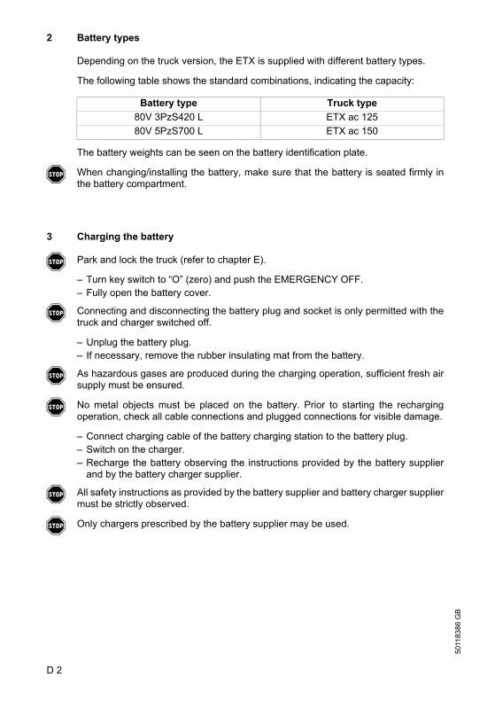
2 Battery types
Depending on the truck version, the ETX is supplied with different battery types.
The following table shows the standard combinations, indicating the capacity:
The battery weights can be seen on the battery identification plate.
f When changing/installing the battery, make sure that the battery is seated firmly inthe battery compartment.
3 Charging the battery
f Park and lock the truck (refer to chapter E).
– Turn key switch to “O” (zero) and push the EMERGENCY OFF.– Fully open the battery cover.
f Connecting and disconnecting the battery plug and socket is only permitted with thetruck and charger switched off.
– Unplug the battery plug.– If necessary, remove the rubber insulating mat from the battery.
f As hazardous gases are produced during the charging operation, sufficient fresh airsupply must be ensured.
f No metal objects must be placed on the battery. Prior to starting the rechargingoperation, check all cable connections and plugged connections for visible damage.
– Connect charging cable of the battery charging station to the battery plug.– Switch on the charger.– Recharge the battery observing the instructions provided by the battery supplier
and by the battery charger supplier.
f All safety instructions as provided by the battery supplier and battery charger suppliermust be strictly observed.
f Only chargers prescribed by the battery supplier may be used.
Battery type Truck type80V 3PzS420 L ETX ac 12580V 5PzS700 L ETX ac 150
5011
8386
GB
D 2
2 Battery types
Depending on the truck version, the ETX is supplied with different battery types.
The following table shows the standard combinations, indicating the capacity:
The battery weights can be seen on the battery identification plate.
f When changing/installing the battery, make sure that the battery is seated firmly inthe battery compartment.
3 Charging the battery
f Park and lock the truck (refer to chapter E).
– Turn key switch to “O” (zero) and push the EMERGENCY OFF.– Fully open the battery cover.
f Connecting and disconnecting the battery plug and socket is only permitted with thetruck and charger switched off.
– Unplug the battery plug.– If necessary, remove the rubber insulating mat from the battery.
f As hazardous gases are produced during the charging operation, sufficient fresh airsupply must be ensured.
f No metal objects must be placed on the battery. Prior to starting the rechargingoperation, check all cable connections and plugged connections for visible damage.
– Connect charging cable of the battery charging station to the battery plug.– Switch on the charger.– Recharge the battery observing the instructions provided by the battery supplier
and by the battery charger supplier.
f All safety instructions as provided by the battery supplier and battery charger suppliermust be strictly observed.
f Only chargers prescribed by the battery supplier may be used.
Battery type Truck type80V 3PzS420 L ETX ac 12580V 5PzS700 L ETX ac 150

D 3
5011
8386
GB
4 Removing and installing the battery
f Only batteries with isolated cells and insulated terminal connections are allowed.
f When changing batteries with the aid of a crane, ensure that the crane is of adequatecapacity (the battery weight is indicated on the battery identification plate at thebattery trough). The lifting gear must pull in a vertical direction to prevent damage tothe battery trough. The hooks must be fastened in such a way that they cannot fallonto the battery cells when the crane hoisting gear is slackened.
f When replacing the battery, make sure only to use the same type as replacement.Additional weights must not be removed and their position not changed.
– Turn key switch to “O” (zero) and push the EMERGENCY OFF.– Fully open the battery cover.
f Connecting and disconnecting the battery plug and socket is only permitted with thetruck and charger switched off.
– Unplug battery connector.– Lift out the frame side walls.
4.1 Removal and replacement with battery trolley
f The truck must be parked on a horizontal surface, so that the battery cannot roll outby itself when the battery securing device is removed.
– Loosen the battery safety device.– Pull out the battery to the side onto the battery trolley provided.
Replacing the battery is done in reverse order.
f After replacing the battery, check all cable and plugged connections for visibledamages and before recommissioning check that:
– the battery safety devices are in place,– the battery cover is fully closed.

5011
8386
GB
D 4
5 Check battery condition, acid level, and acid concentration
– The warning notes of the battery manufacturer must be observed.– Check the battery housing for cracks and leaking acid.– Remove oxidation residue at the battery terminals and grease the terminals with
acid-free grease.– Unscrew the plugs and check the acid level.
The acid level must be at least 10-15 mm above the plates’ top edge.– Check the acid concentration according to the battery manufacturer’s instructions
using an acid pipette and screw in the plugs again when finished.– If required, recharge the battery.
6 Battery discharge indicator
After turning the key in the keyswitchclockwise and pulling the EMERGENCYOFF switch, the battery charge indicatorshow the remaining capacity. If theremaining capacity is at 30% the displayflashes. Below 20% capacity the lift cut-off is activated.
Once the lift cut-off has been activated,it is only re-enabled at a battery capacityof 40%.
+-
50%
E 1
5011
8386
GB
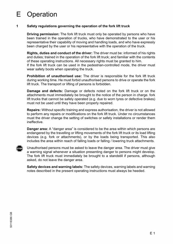
E Operation1 Safety regulations governing the operation of the fork lift truck
Driving permission: The fork lift truck must only be operated by persons who havebeen trained in the operation of trucks, who have demonstrated to the user or hisrepresentative their capability of moving and handling loads, and who have expresslybeen charged by the user or his representative with the operation of the truck.
Rights, duties and conduct of the driver: The driver must be: informed of his rightsand duties; trained in the operation of the fork lift truck; and familiar with the contentsof these operating instructions. All necessary rights must be granted to him.If the fork lift truck can be used in the pedestrian-controlled mode, the driver mustwear safety boots when operating the truck.
Prohibition of unauthorised use: The driver is responsible for the fork lift truckduring working time. He must forbid unauthorised persons to drive or operate the forklift truck. The transport or lifting of persons is forbidden.
Damage and defects: Damage or defects noted on the fork lift truck or on theattachments must immediately be brought to the notice of the person in charge. forklift trucks that cannot be safely operated (e.g. due to worn tyres or defective brakes)must not be used until they have been properly repaired.
Repairs: Without specific training and express authorisation, the driver is not allowedto perform any repairs or modifications on the fork lift truck. Under no circumstancesmust the driver change the setting of switches or safety installations or render themineffective.
Danger area: A “danger area” is considered to be the area within which persons areendangered by the travelling or lifting movements of the fork lift truck or its load liftingdevices (e.g. fork or attachments), or by the loads being transported. This alsoincludes the area within reach of falling loads or falling / lowering truck attachments.
f Unauthorised persons must be asked to leave the danger area. The driver must givea warning signal whenever a situation presenting danger to persons might develop.The fork lift truck must immediately be brought to a standstill if persons, althoughasked, do not leave the danger area.
Safety devices and warning labels: The safety devices, warning labels and warningnotes described in the present operating instructions must always be heeded.
E 1
5011
8386
GB
E Operation1 Safety regulations governing the operation of the fork lift truck
Driving permission: The fork lift truck must only be operated by persons who havebeen trained in the operation of trucks, who have demonstrated to the user or hisrepresentative their capability of moving and handling loads, and who have expresslybeen charged by the user or his representative with the operation of the truck.
Rights, duties and conduct of the driver: The driver must be: informed of his rightsand duties; trained in the operation of the fork lift truck; and familiar with the contentsof these operating instructions. All necessary rights must be granted to him.If the fork lift truck can be used in the pedestrian-controlled mode, the driver mustwear safety boots when operating the truck.
Prohibition of unauthorised use: The driver is responsible for the fork lift truckduring working time. He must forbid unauthorised persons to drive or operate the forklift truck. The transport or lifting of persons is forbidden.
Damage and defects: Damage or defects noted on the fork lift truck or on theattachments must immediately be brought to the notice of the person in charge. forklift trucks that cannot be safely operated (e.g. due to worn tyres or defective brakes)must not be used until they have been properly repaired.
Repairs: Without specific training and express authorisation, the driver is not allowedto perform any repairs or modifications on the fork lift truck. Under no circumstancesmust the driver change the setting of switches or safety installations or render themineffective.
Danger area: A “danger area” is considered to be the area within which persons areendangered by the travelling or lifting movements of the fork lift truck or its load liftingdevices (e.g. fork or attachments), or by the loads being transported. This alsoincludes the area within reach of falling loads or falling / lowering truck attachments.
f Unauthorised persons must be asked to leave the danger area. The driver must givea warning signal whenever a situation presenting danger to persons might develop.The fork lift truck must immediately be brought to a standstill if persons, althoughasked, do not leave the danger area.
Safety devices and warning labels: The safety devices, warning labels and warningnotes described in the present operating instructions must always be heeded.

5011
8386
GB
E 2
2 Description of Operating and Display Elements
2.1 Operating and display elements at the control panel
Item Operating or display element
Function
1 Steering wheel t Steers truck in desired direction2 Display t Displays operating information and warnings3 Lifting height
preselectiont Range selection
4 Lifting height preselection
t Shelf selection
5 Travel direction switch t Select desired travel direction6 Rotating seat switch t To turn driver seat7 Key switch t Switches control voltage on and off8 Emergency-OFF switch t The power circuits are interrupted, all electrical
functions switch off9 Hydraulics control knob t Lifting and lowering, traversing and swivelling
10 Pushbutton “Warning signal”
t When actuated, triggers warning signal
11 Pushbutton “Traversing load-carrying unit”
t Switches the hydraulics control knob to function “Traversing load-carrying unit”
12 Pushbutton “Turning fork arm carriage”
t Switches the hydraulics control knob to function “Turning fork arm carriage”
t = Series equipment o = Optional equipment
1 2 3 4
56
7
8
9101112

E 3
5011
8386
GB
2.2 Foot-operated elements
Item Operating or display element
Function
13 Accelerator pedal t Continuous control of travel speed14 Brake pedal t Actuates the load wheel brake15 Dead man pushbutton
(foot-operated switch)t Disengage the immobilising brake.
When actuated, disengages the spring-loaded brake and releases the travel motion. Releasing the dead man pushbutton results in immediate deceleration of the truck to standstill.
t = Series equipment o = Optional equipment
131415

5011
8386
GB
E 4
2.3 Operating and display elements at the display
Symbols in the upper section
Item Symbol Operating or display element
Function
10 Pushbutton “Quit submenu”
t Sets the menu from swivel/traverse to basic display
11 Display of possible travel speed: Snail Rabbit
t
Inching Maximum speed
12 Display “Guide wire detection”
IG Sensors that have detected the guide wire are shown with dark background
10
11
12
13 16 15 17
18
19
20
2122

E 5
5011
8386
GB
13 Steering angle indication (Changes with the display guidance systems)
t
RG
IG
Shows the current steering angle in relation to the centre position After tracking-in, centre position is shown permanently Steering angle display extinguishes and is replaced by guide wire symbols
15 Display “Operating hours”
t Shows the number of operating hours since first putting into service
16 Display “Time of day” t Displays the time of day17 Battery discharge
indicatort Shows the charging condition of the
battery (remaining capacity in percent)18 Display “Immobilising
brake ON”t Illuminates, when the immobilising brake
has been engaged19 Display
“EMERGENCY STOP”
t Illuminates, when the EMERGENCY STOP facility was automatically triggered
20 Display “Service required / fault”
t Illuminates, when service is required or a malfunction has occurred
Item Symbol Operating or display element
Function

5011
8386
GB
E 6
Symbols and pushbuttons in the lower section
The pushbuttons (22) under the respectively shown symbols (21) activate oracknowledge the functions associated with them. The symbol is then shown with darkbackground.
Symbol Operating or display element
Function
WarningsDisplay “Height-dependent lift limitation”
o Appears when the height-dependent lift limitation has been activated
Pushbutton “Override height-dependent lift limitation”
Overrides the height-dependent lift limitation (display shown with dark background); the maximum clearance must be observed
Display “Lowering limitation”
o Indicates that the automatic lowering limitation was triggered
Pushbutton “Override lowering limitation”
Overrides the lowering limitation, control with hydraulics control knob
Display “Drive cut-off” o Indicates that the automatic, height-dependent drive cut-off has been activated
Pushbutton “Override drive cut-off”
Overrides the automatic height-dependent drive cut-off
Display “End-of-aisle safety device” (optional)
o Indicates that the end-of-aisle safety device has been triggered, the truck is decelerated
Display “Personnel protection facility” (PSS)
o Indicates that the personnel protection facility has detected persons/objects in the aisle, the truck is decelerated.
Pushbutton “Personnel protection facility” (PSS)
Overrides the protection function and enables inching with sufficient safety distance to the obstacle.If a personnel protection facility is installed, you must observe the separate operating instructions.
Display “Call warnings submenu”
o Indicates that several warnings (e. g. slack-chain safety device, height-dependent lift cut-off) have been issued.
Quit submenu “Warnings”
Displays individual warnings
Quit submenu “Warnings”
o Indicates that the submenu can be left
Pushbutton “Quit warnings submenu”
Sets the submenu from “Warnings” to basic menu

E 7
5011
8386
GB
Guidance systemsPushbutton “Guidance ON” (dark background, when active)
t
RG
IG
Indicates forced guidance in the aisle:
Display “Rail guidance” (Drive wheel set straight)
Indicates that inductive guidance is activePushbutton “Guidance ON”
RG
IG
Sets the drive wheel in straight position
Activates the tracking-in process (and frequency selection for multi-frequency)
– “Tracking-in”
– “Wire-guided”
– “Deviation from guidewire”
IG
IG
IG
– if the truck tracks-in to the guide wire(inductive guidance)
– if the truck is force-guided on the guidewire
– if the truck has deviated in uncontrolledmanner from the guide wire and theforced guidance
Pushbutton “Select frequency 1” (and other frequencies in the same way) (Submenu “Guidance ON”)
o
IG
Indicates that guidance is possible via frequency 1
Pushbutton “Select frequency 1” (and other frequencies in the same way)
Activates guidance via frequency 1 (automatic exit from submenu after pushing for 1 second)
Fork operationDisplay “Toggle menu synchronous turning”
t Toggling the display menu to the “Synchronous turning” functions
Pushbutton “Toggle menu synchronous turning”
Activates synchronous turning menu toggling
Display “Synchronous fork left turn”
t Indicates that synchronous left turning/right traversing of the fork is possible
Pushbutton “Synchronous fork left turn”
Activates left turning of the fork and simultaneously controls right traversing of the boom by using the hydraulics control knob
Display “Automatic synchronous fork left turn”
Indicates that automatic synchronous left turning/right traversing of the fork is possible
Pushbutton “Automatic synchronous fork left turn”
Activates left turning of the fork and simultaneous right traversing of the boom
Symbol Operating or display element
Function

5011
8386
GB
E 8
Display “Synchronous fork right turn”
Indicates that synchronous right turning/left traversing of the fork is possible
Pushbutton “Synchronous fork right turn”
Activates right turning of the fork and simultaneously controls left traversing of the boom by using the hydraulics control knob
Display “Automatic synchronous fork right turn”
Indicates that automatic synchronous right turning/left traversing of the fork is possible
Pushbutton “Automatic synchronous fork right turn”
Activates right turning of the fork and simultaneous left traversing of the boom
Display “Synchronous turn to fork centre position”
Indicates that positioning of the fork in centre position (fork arms to the front) is possible
Pushbutton “Synchronous turn to fork centre position”
Activates swivelling with automatic stop of the fork movement in centre position, controlling the boom traversing with the hydraulics control knob
Display “Automatic synchronous turn to fork centre position”
Indicates that automatic positioning of the fork in centre position (fork arms to the front) is possible
Pushbutton “Automatic synchronous turn to fork centre position”
Activates swivelling with automatic stop of the fork movement in centre position, simultaneous automatic boom traversing with stop in centre position
Display “Telescopic fork” Indicates that the telescopic fork can be operated
Pushbutton “Telescopic fork”
Activates the telescopic fork, controlled by hydraulics control knob
Display “2nd stacking depth”
Indicates that the 2nd stacking depth is enabled
Pushbutton “2nd stacking depth”
Activates the 2nd stacking depth, controlled by hydraulics control knob
Display “Fork tilt” Indicates that fork tilting is enabledPushbutton “Fork tilting” Activates the fork tilt, controlled by
hydraulics control knobDisplay “Load-carrying unit”
Indicates that the load-carrying unit can be operated
Pushbutton “Load-carrying unit”
Activates control of the load-carrying unit, controlled by hydraulics control knob
Symbol Operating or display element
Function

E 9
5011
8386
GB
Fork arm adjustmentDisplay “Symmetrical fork arm adjustment”
o Indicates that the fork arm adjustment can be operated
Pushbutton “Symmetrical fork arm adjustment”
Activates fork arm adjustment for simultaneous operation of the hydraulics control knob, Turn right = fork arms to inside; turn right = fork arms to outside
t = Series equipment o = Optional equipmentRG = Rail Guidance IG = Inductive Guidance
Symbol Operating or display element
Function
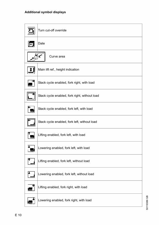
5011
8386
GB
E 10
Additional symbol displays
Turn cut-off override
Date
Curve area
Main lift ref., height indication
Stack cycle enabled, fork right, with load
Stack cycle enabled, fork right, without load
Stack cycle enabled, fork left, with load
Stack cycle enabled, fork left, without load
Lifting enabled, fork left, with load
Lowering enabled, fork left, with load
Lifting enabled, fork left, without load
Lowering enabled, fork left, without load
Lifting enabled, fork right, with load
Lowering enabled, fork right, with load
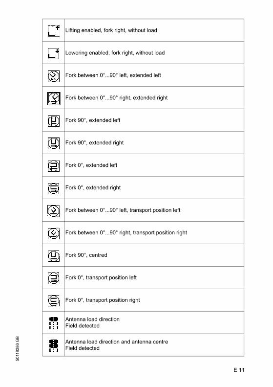
E 11
5011
8386
GB
Lifting enabled, fork right, without load
Lowering enabled, fork right, without load
Fork between 0°...90° left, extended left
Fork between 0°...90° right, extended right
Fork 90°, extended left
Fork 90°, extended right
Fork 0°, extended left
Fork 0°, extended right
Fork between 0°...90° left, transport position left
Fork between 0°...90° right, transport position right
Fork 90°, centred
Fork 0°, transport position left
Fork 0°, transport position right
Antenna load directionField detected
Antenna load direction and antenna centreField detected
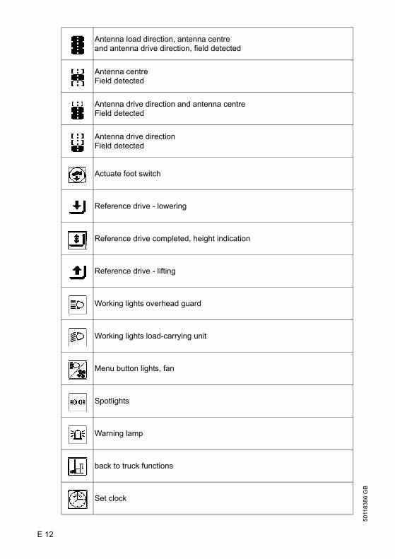
5011
8386
GB
E 12
Antenna load direction, antenna centreand antenna drive direction, field detected
Antenna centreField detected
Antenna drive direction and antenna centreField detected
Antenna drive directionField detected
Actuate foot switch
Reference drive - lowering
Reference drive completed, height indication
Reference drive - lifting
Working lights overhead guard
Working lights load-carrying unit
Menu button lights, fan
Spotlights
Warning lamp
back to truck functions
Set clock

E 13
5011
8386
GB
Hours minus
Hours plus
Minutes minus
Minutes plus
Fan
Toggle in submenuSide shift and fork arm adjustment
Personnel protection facility active, flashing not active
Personnel protection facility forced braking, acknowledge not required
Traversing telescopic fork
Side shift
Fork front position
Load-carrying unit in transport position
Turn steering wheel left to drive straight
Turn steering wheel right to drive straight
Straight travel

5011
8386
GB
E 14
Drive wheel position indicator
2. Stacking depth
End-of-aisle safety device override
Zone 1 to zone 7
Clamp menu button
Open clamp
Close clamp
Travel direction indicator drive direction
Travel direction indicator load direction
Horizontal positioning - position reached
5011
8386
GB
E 14
Drive wheel position indicator
2. Stacking depth
End-of-aisle safety device override
Zone 1 to zone 7
Clamp menu button
Open clamp
Close clamp
Travel direction indicator drive direction
Travel direction indicator load direction
Horizontal positioning - position reached

E 15
5011
8386
GB
Display symbol assignment
E 15
5011
8386
GB
Display symbol assignment

5011
8386
GB
E 16
Display symbol assignment
Time of day
Height display
Operating hours
5011
8386
GB
E 16
Display symbol assignment
Time of day
Height display
Operating hours

E 17
5011
8386
GB
3 Starting up the truck
f Before starting or operating the truck, or before lifting any loads, the driver has tomake sure that nobody is within the danger area.
The operating condition of the truck after switching on is indicated by the symbols inthe display.
3.1 Reference drive (Commissioning)
A reference drive must be performed every time before putting a truck into service,i.e. when the key switch was set to OFF.
– Turn key switch to ON– Step on the foot switch– Swivel hydraulics control knob to “Lifting” until the lift switches off automatically,
then fully lower it again.
This is the only way the control system enables all movements of the truck at fullspeed, and the height preselection is adjusted.
Lifting and lowering is indicated by the symbols:
Reference drive: lifting
Reference drive: lowering
Re-referencing of the load-carrying unit
If the side-shift or the boom rotation is changed while the truck is switched off, error183 or 203 is displayed when the truck is switched on and rotating and traversingmust be referenced.
The side-shift is referenced by moving the side-shift across the index (centre ofattachment).
The rotation sensor system (boom) is referenced by moving towards a limit stop ofthe rotation function for at least one second.
Successful referencing is indicated by removal of the corresponding symbol duringreferencing.
Rotation reference travel Traversing reference travel

5011
8386
GB
E 18
3.2 Checks and operations to be performed before starting daily work
– Check the entire truck outside for obvious damages or leaks.– Check battery mounting, cable connections for damages and tight seat.– Check battery plug for tight seat.– Check overhead guard for damages.– Check load-carrying unit for noticeable damages such as cracks, bends or heavy
abrasions on load fork.– Check condition of fork arm locks and stop bolts to prevent pushing the fork arms
out to the side.– Check load wheels for damages.– Check whether the load chains are tensioned uniformly.– Check whether all safety devices are operational and function properly.– For rail guided trucks, check guide rollers for concentric running and damages.– Check function of service brake and immobilising brake.– Check function of end-of-aisle safety device.– Check braking distance when EMERGENCY OFF switch is actuated during travel.– Check tilting safety for firm seating.
3.3 Mounting and descending from the truck
When mounting the truck anddescending from the truck, firmly grabthe handle at the driver seat. Descentfrom the truck only backwards.
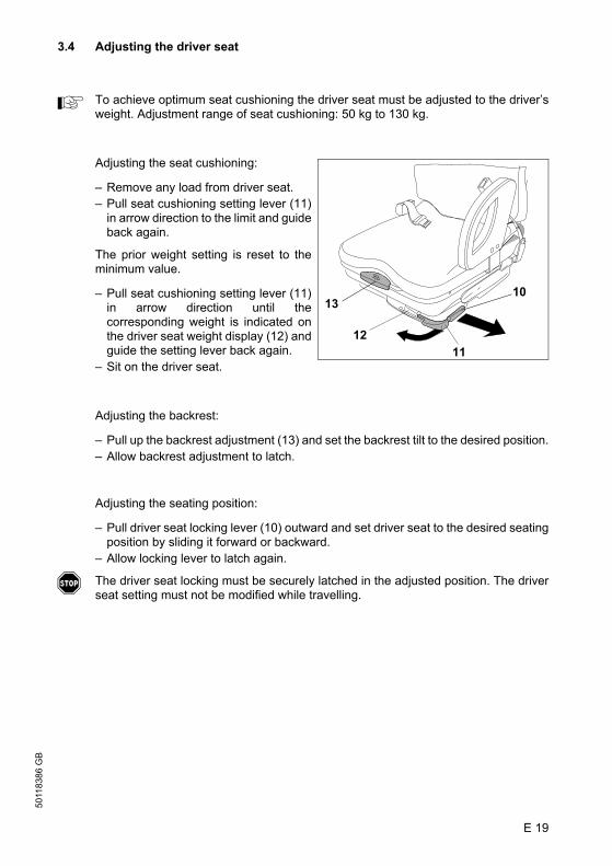
E 19
5011
8386
GB
3.4 Adjusting the driver seat
A To achieve optimum seat cushioning the driver seat must be adjusted to the driver’sweight. Adjustment range of seat cushioning: 50 kg to 130 kg.
Adjusting the seat cushioning:
– Remove any load from driver seat.– Pull seat cushioning setting lever (11)
in arrow direction to the limit and guideback again.
The prior weight setting is reset to theminimum value.
– Pull seat cushioning setting lever (11)in arrow direction until thecorresponding weight is indicated onthe driver seat weight display (12) andguide the setting lever back again.
– Sit on the driver seat.
Adjusting the backrest:
– Pull up the backrest adjustment (13) and set the backrest tilt to the desired position.– Allow backrest adjustment to latch.
Adjusting the seating position:
– Pull driver seat locking lever (10) outward and set driver seat to the desired seatingposition by sliding it forward or backward.
– Allow locking lever to latch again.
f The driver seat locking must be securely latched in the adjusted position. The driverseat setting must not be modified while travelling.
1211
1310

5011
8386
GB
E 20
3.5 Safety restraint belt (option)
f Put on the safety restraint belt every time before moving the industrial truck. The belt protects you from serious injuries.
Protect the restraint belt from dirt (e. g. cover up at standstill) and clean regularly. Ifthe belt catch or retractor is frozen, let it thaw and allow to dry to avoid freezing again.
A The drying temperature of the warm air must not exceed +60°!
f Modifications to the restraint belt are not permitted! Increased risk through malfunctions.
– Replace restraint belts after an accident.– Use only original spare parts for retrofits and repairs.
f Damaged or non-functioning restraint belts must be exchanged by authorised dealersor in the subsidiary.
Managing extraordinary situations
f If the industrial trucks is about to turnover, do not unfasten the belt and do nottry to jump off the truck under nocircumstances.Jumping off increases the risk ofsuffering injuries!
Correct behaviour:
– Grip the steering wheel with bothhands and support yourself with thefeet.
– Tilt body against turning direction.
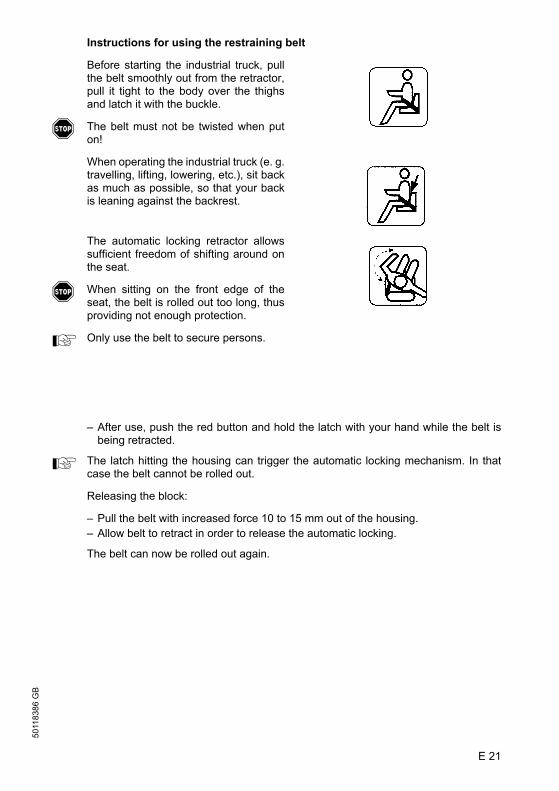
E 21
5011
8386
GB
Instructions for using the restraining belt
Before starting the industrial truck, pullthe belt smoothly out from the retractor,pull it tight to the body over the thighsand latch it with the buckle.
f The belt must not be twisted when puton!
When operating the industrial truck (e. g.travelling, lifting, lowering, etc.), sit backas much as possible, so that your backis leaning against the backrest.
The automatic locking retractor allowssufficient freedom of shifting around onthe seat.
f When sitting on the front edge of theseat, the belt is rolled out too long, thusproviding not enough protection.
A Only use the belt to secure persons.
– After use, push the red button and hold the latch with your hand while the belt isbeing retracted.
A The latch hitting the housing can trigger the automatic locking mechanism. In thatcase the belt cannot be rolled out.
Releasing the block:
– Pull the belt with increased force 10 to 15 mm out of the housing.– Allow belt to retract in order to release the automatic locking.
The belt can now be rolled out again.
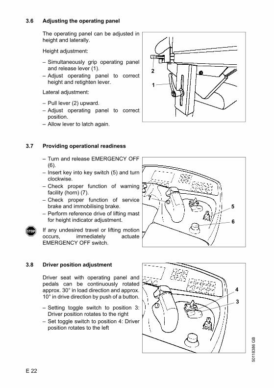
5011
8386
GB
E 22
3.6 Adjusting the operating panel
The operating panel can be adjusted inheight and laterally.
Height adjustment:
– Simultaneously grip operating paneland release lever (1).
– Adjust operating panel to correctheight and retighten lever.
Lateral adjustment:
– Pull lever (2) upward.– Adjust operating panel to correct
position.– Allow lever to latch again.
3.7 Providing operational readiness
– Turn and release EMERGENCY OFF(6).
– Insert key into key switch (5) and turnclockwise.
– Check proper function of warningfacility (horn) (7).
– Check proper function of servicebrake and immobilising brake.
– Perform reference drive of lifting mastfor height indicator adjustment.
f If any undesired travel or lifting motionoccurs, immediately actuateEMERGENCY OFF switch.
3.8 Driver position adjustment
Driver seat with operating panel andpedals can be continuously rotatedapprox. 30° in load direction and approx.10° in drive direction by push of a button.
– Setting toggle switch to position 3:Driver position rotates to the right
– Set toggle switch to position 4: Driverposition rotates to the left
1
2
5
6
7
3
4
E 23
5011
8386
GB
4 Operation of the truck
4.1 Safety regulations applicable when operating the truck
Driving lanes and work areas: Only such lanes and routes that are speciallyallocated for truck traffic may be used. Driving lane surfaces must be sufficientlypaved and free of bumps as much as possible. Transfers must be levelled and, ifnecessary, equipped with ramps, so that they can be crossed as bumpless aspossible. All driving lanes must be clearly marked and clear of obstacles.Unauthorised persons must stay away from work areas. Loads must only be storedat places specially provided for this purpose.
Driving conduct: The travelling speed must be adapted to the prevailing localconditions. The truck must be driven at slow speed when negotiating bends or narrowpassages, when passing through swing doors and at blind spots. The driver mustalways observe an adequate braking distance between the truck and the vehicle infront and he must be in control of his truck at all times. Sudden stopping (except inemergencies), rapid U-turns and overtaking at dangerous or blind spots is notpermitted. The truck should be driven in drive direction, i. e. with the load pointing tothe rear. Leaning or reaching out from the work area is prohibited.
Visibility during travel: The driver must look in the direction of travel and mustalways have a clear view of the route ahead. If load units are transported that obstructthe view, a second person for guiding must be present when travelling in the frontyard. During this procedure there must be continuous visual and speech contactbetween driver and guide. If the contact is interrupted - even if only temporarily - thedriver must stop immediately and may only continue travel when contact has been re-established.
Negotiating slopes and inclines: Driving on slopes and inclines is prohibited!
Use of lifts and driving on loading platforms: Using lifts and driving on loadingplatforms is prohibited!

5011
8386
GB
E 24
Travelling in narrow aisles: Before driving into a narrow aisle the driver must checkwhether persons or other industrial trucks are in this narrow aisle. If this is the caseand if no sufficient measures to protect personnel or to avoid collision with otherindustrial trucks, the driver must not drive into this narrow aisle. A special source of danger in narrow aisles are objects that project from the racking.Therefore, always watch the full height of the narrow aisle.The floor must be clear of any obstacles. The floor surface must be clean, in order toachieve sufficient traction.If a narrow aisle is equipped with inductive guidance and the guidance system isdefective or switched off, only trained and authorised personnel may drive the truckout of the narrow aisle.
Nature of the loads carried: Only loads that have been safely and correctly securedmust be carried. Never transport any load that protrude beyond the load forks to thefront.
Flattening of wheels: When the truck is parked for extended periods, the runningsurface of the tyres will flatten. However, this does not affect the travel safety orstability of the truck, as the flattening will disappear after travelling for a while.
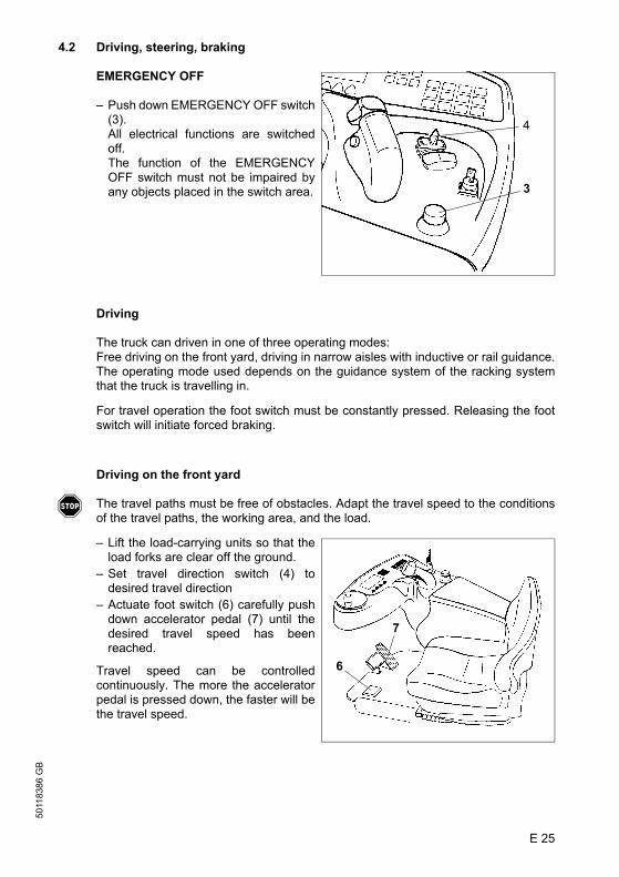
E 25
5011
8386
GB
4.2 Driving, steering, braking
EMERGENCY OFF
– Push down EMERGENCY OFF switch(3).All electrical functions are switchedoff.The function of the EMERGENCYOFF switch must not be impaired byany objects placed in the switch area.
Driving
The truck can driven in one of three operating modes:Free driving on the front yard, driving in narrow aisles with inductive or rail guidance.The operating mode used depends on the guidance system of the racking systemthat the truck is travelling in.
For travel operation the foot switch must be constantly pressed. Releasing the footswitch will initiate forced braking.
Driving on the front yard
f The travel paths must be free of obstacles. Adapt the travel speed to the conditionsof the travel paths, the working area, and the load.
– Lift the load-carrying units so that theload forks are clear off the ground.
– Set travel direction switch (4) todesired travel direction
– Actuate foot switch (6) carefully pushdown accelerator pedal (7) until thedesired travel speed has beenreached.
Travel speed can be controlledcontinuously. The more the acceleratorpedal is pressed down, the faster will bethe travel speed.
3
4
6
7
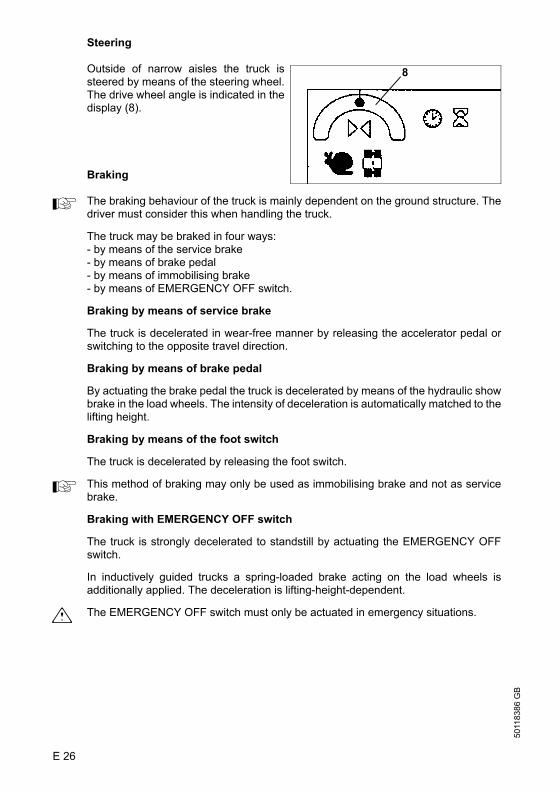
5011
8386
GB
E 26
Steering
Outside of narrow aisles the truck issteered by means of the steering wheel.The drive wheel angle is indicated in thedisplay (8).
Braking
A The braking behaviour of the truck is mainly dependent on the ground structure. Thedriver must consider this when handling the truck.
The truck may be braked in four ways:- by means of the service brake- by means of brake pedal- by means of immobilising brake- by means of EMERGENCY OFF switch.
Braking by means of service brake
The truck is decelerated in wear-free manner by releasing the accelerator pedal orswitching to the opposite travel direction.
Braking by means of brake pedal
By actuating the brake pedal the truck is decelerated by means of the hydraulic showbrake in the load wheels. The intensity of deceleration is automatically matched to thelifting height.
Braking by means of the foot switch
The truck is decelerated by releasing the foot switch.
A This method of braking may only be used as immobilising brake and not as servicebrake.
Braking with EMERGENCY OFF switch
The truck is strongly decelerated to standstill by actuating the EMERGENCY OFFswitch.
In inductively guided trucks a spring-loaded brake acting on the load wheels isadditionally applied. The deceleration is lifting-height-dependent.
m The EMERGENCY OFF switch must only be actuated in emergency situations.
8

E 27
5011
8386
GB
Travelling in narrow aisles
m Unauthorised personnel and through-traffic for personnel is not allowed in narrowaisles (travel paths for trucks in racking systems without safety distance for oncomingpersons). Such working areas must be marked accordingly. Existing protectiondevices at trucks or the racking system for preventing dangerous situations andprotecting personnel must be checked on a daily basis. Such devices must not berendered unusable, must not be misused, maladjusted, or removed. Malfunctions onsafety devices must be reported and repaired immediately.
A Before driving into a narrow aisle the driver must check whether persons or othertrucks are in this narrow aisle. Only free narrow aisles may be entered. If personnelis in the narrow aisle, the operation must be stopped immediately.
A Driving into narrow aisles is only allowed with trucks that have been designed for thisoperation. If a narrow aisle is equipped with a mechanical guidance system and theguidance system is defective or switched off, the truck may only be driven out of thenarrow aisle at inching speed.
Diagonal travel
Diagonal travel is possible bysimultaneously actuating hydrauliccontrol lever (1) and stepping downaccelerator pedal (2) (simultaneoustravelling and lifting or lowering).
Trucks with rail guidance
f The rail height must be at least 40 mm.
Rail-guided trucks are equipped with sensors that activate the aisle detection whenentering the rack aisles.
– Position the truck at reduced speed in front of the narrow aisles, so that is alignedwith the narrow aisle and its markings.
A Observe the signs affixed to the travel paths.
– Slowly drive truck into the narrow aisle.
Observe that the guide rollers of the truck fully thread into the guide rails of the narrowaisle.
2
1
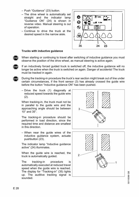
5011
8386
GB
E 28
– Push “Guidance” (23) button.– The drive wheel is automatically set
straight and the indicator lamp“Guidance ON” (24) is shown inreverse video. Manual steering is outof operation.
– Continue to drive the truck at thedesired speed in the narrow aisle.
Trucks with inductive guidance
f When starting or continuing to travel after switching of inductive guidance you mustobserve the position of the drive wheel, as manual steering is active again.
f If an inductively forced guided truck is switched off, the inductive guidance will nolonger be active when the truck is switched on again. Danger of accidents! The truckmust be tracked in again.
f During the tracking-in procedure the truck’s rear section might break out of line undercertain circumstances, if the front sensor (3) has already crossed the guide wirebefore the button “Inductive guidance ON” has been pushed.
– Drive the truck (1) diagonally atreduced speed towards the guide wire(2).
When tracking-in, the truck must not bein parallel to the guide wire and theapproaching angle should be between10° and 35°.
The tracking-in procedure should beperformed in load direction, since therequired time and distance are smallestin this direction.
– When near the guide wires of theinductive guidance system, actuatepushbutton (23).
The indicator lamp “Inductive guidanceactive” (24) illuminates.
When the guide wire is reached, thetruck is automatically guided.
The tracking-in procedure isautomatically executed at reduced travelspeed when the guide wire is reached.The display for “Tracking-in” (35) lightsup. The auditive tracking signal issounded.
3
1
2

E 29
5011
8386
GB
The inductive forced steering takes oversteering of the truck and turns it to theguide wire.
After the truck is exactly tracking theguide wire the tracking-in procedure iscompleted. The display (36) changes to“Wire-guided”. The tracking-in signal isno longer sounded. The truck is nowforce-guided.The maximum travel speed is enabled.
To leave the guide wire the pushbutton(23) for inductive forced steering mustbe actuated.
f Switching over to manual steering may only be performed when the entire truck hasleft the rack aisle.
If t during inductive guidance of the truck the guiding antenna leaves the predefinedlevel area of the guide wire, an emergency stop is initiated immediately.
23
36

5011
8386
GB
E 30
4.3 Lifting - lowering - traversing - swivelling
f Danger of pinching when swivelling or traversing the fork arms.No personnel is allowed in the danger zone when swivelling, traversing, orsynchronous turning the load-carrying unit.
Lifting - lowering (load-carrying unit)
– Turn hydraulic control knob (2)clockwise = lifting counter-clockwise = lowering
A The lifting and lowering speed isproportional to turning the hydrauliccontrol knob.
The maximum lifting speed is achieved,when carrying position swivel/traverse isindicated in the display.
A Lowering is only possible when the truckis ready for operation.
Traversing (boom)
– Release foot switch.– Actuate pushbutton (11) (= Traversing
load-carrying unit).– Simultaneously turn hydraulic control
knob (2).Turning clockwise = Traversing rightTurning counter-clockwise =Traversing left
The traversing speed is proportional toturning the hydraulic control knob.
2
2
11

E 31
5011
8386
GB
Swivelling (fork arm carriage)
– Release foot switch.– Actuate pushbutton (9) (= fork arm
carriage swivel).– Turn hydraulic control knob (2).
Turning clockwise = Swivelling rightTurning counter-clockwise =Swivelling left
The swivelling speed is proportional toturning the hydraulic control knob.
Simultaneous traversing and swivelling of the fork arm carriage (manually)
f Danger of pinching when swivelling or shifting the fork arms.No personnel is allowed in the danger zone when swivelling, shifting, or synchronousturning the load-carrying unit.
A When shifting the load-carrying unit the fork arm carriage is swivelled.The turning speed cannot be changed.The traversing speed is proportional to turningthe hydraulic control knob.
– Release foot switch. – Actuate pushbutton (27).– Turning hydraulic control knob (2)
counter-clockwise = Swivelling thefork arm carriage to the right andtraversing the boom to the left.
– Actuate pushbutton (29).– Turning hydraulic control knob (2)
counter-clockwise = Swivelling thefork arm carriage to the left andtraversing the boom to the right.
29
2
2729

5011
8386
GB
E 32
Traversing the telescopic fork
– Actuate pushbutton for “Traversing load-carrying unit”.– Turn hydraulic control knob:
clockwise = traversing to the rightcounter-clock wise = traversing to the left
A The traversing speed is proportional to turning the hydraulic control knob.
The telescopic fork is automatically stopped in centre position. After releasing thehydraulic control knob and actuating it again the telescopic fork can be shifted furtherto the left or right.
A The hydraulic control knob can be used to fine-control the movements of the load-carrying unit.
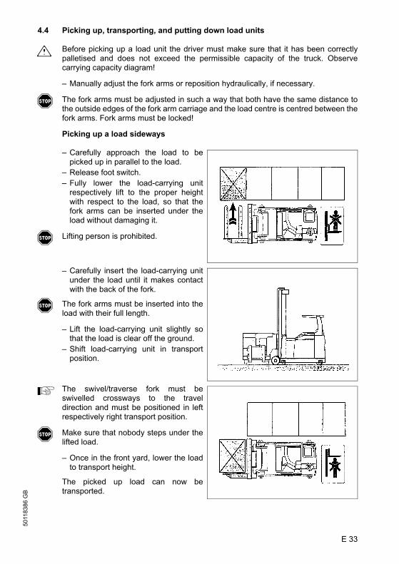
E 33
5011
8386
GB
4.4 Picking up, transporting, and putting down load units
m Before picking up a load unit the driver must make sure that it has been correctlypalletised and does not exceed the permissible capacity of the truck. Observecarrying capacity diagram!
– Manually adjust the fork arms or reposition hydraulically, if necessary.
f The fork arms must be adjusted in such a way that both have the same distance tothe outside edges of the fork arm carriage and the load centre is centred between thefork arms. Fork arms must be locked!
Picking up a load sideways
– Carefully approach the load to bepicked up in parallel to the load.
– Release foot switch.– Fully lower the load-carrying unit
respectively lift to the proper heightwith respect to the load, so that thefork arms can be inserted under theload without damaging it.
f Lifting person is prohibited.
– Carefully insert the load-carrying unitunder the load until it makes contactwith the back of the fork.
f The fork arms must be inserted into theload with their full length.
– Lift the load-carrying unit slightly sothat the load is clear off the ground.
– Shift load-carrying unit in transportposition.
A The swivel/traverse fork must beswivelled crossways to the traveldirection and must be positioned in leftrespectively right transport position.
f Make sure that nobody steps under thelifted load.
– Once in the front yard, lower the loadto transport height.
The picked up load can now betransported.

5011
8386
GB
E 34
Picking up a load with swivel/traverse fork from the front
– Swivel the swivel/traverse fork 90°away from the transport position andtraverse to the centre axis of the truck.
A The swivel/traverse fork is nowpositioned in travel direction.
– Fully lower the swivel/traverse forkrespectively lift to the proper heightwith respect to the load, so that thefork arms can be inserted under theload without damaging it.
f Lifting person is prohibited.
– Carefully insert the fork arms underthe load until it makes contact with theback of the fork.
f The fork arms must be inserted into theload with their full length.
– Release foot switch.– Lift the swivel/traverse fork slightly so
that the load is clear off the ground.– Step on the foot switch.– Drive the truck carefully in drive
direction only as far until the load isfree.
This operating mode is only allowed atthe stack!
f Make sure that nobody steps under thelifted load.
– Release foot switch.– Lower the load.– Move the swivel/traverse fork in
transport position.
A The swivel/traverse fork must beswivelled crossways to the traveldirection and must be positioned in leftrespectively right transport position.
The picked up load can now betransported.

E 35
5011
8386
GB
Picking up and setting down a load in the narrow aisle
f In narrow aisles the operator must payspecial attention. The narrow aisle mustnot be entered when persons or anothertruck is in the narrow aisle. Also duringthe stacking procedure the driver mustmake sure that persons or trucks do notenter the narrow aisle. If this is the casethe truck must be stopped immediatelyand a warning signal must be issued.
– Position the truck horizontally andvertically directly in front of the rackshelf so that it does not touch the rackwith the load or load-carrying unit.
– Pick up or set down the load (refer tosection “Picking up a load sideways”respectively “Setting down a load”.
f Special care must be taken whenworking at the first rack shelves, as thetruck is partly located outside the narrowaisle and persons and trucks moving inthe travel range may be injured resp.damaged.
Transporting loads
A Observe clearance heights and width at doors and between racks.
f If the load is stacked high and obstructs the view, a second person must be presentfor guiding.
– Sensitively accelerate the truck andalways be prepared to apply thebrakes.
f Adapt the travel speed to the condition ofthe travel path and to the transportedload. Watch the traffic at intersectionsand passages and use the help of asecond person when negotiating unclearsections.

5011
8386
GB
E 36
Setting down loads
– Carefully approach the storageposition with the truck.
f Before the load can be set down thedriver must verify that the storageposition is suited for the load(dimensions and carrying capacity).
– Release foot switch.– Lift the load-carrying unit as far until
the load can be inserted into thestorage position without colliding.
– Carefully push the load into thestorage position.
– Sensitively lower the load-carryingunit until the fork arms are clear off theload.
m Avoid setting down the load heavily, inorder not to damage load and load-carrying unit.
– Carefully pull load-carrying unit out ofthe load.
– Fully lower the load-carrying unit.
4.5 Lifting height preselection
To pick up or set down loads at preselected storage locations, the truck must beadjusted to the warehouse facilities. The work required for this purpose may only becarried out by customer service.
Storage location recognition (zones)
The zones are entered via number keys or input keys F1 - F7.
Picking up or setting down load in preselected storage locations with heightpreselection:
– Drive truck into the corresponding narrow aisle– Enter the shelf number.
The shelf number is entered via the number keys.The shelf number can be entered as a single digit (1- 9) or two digits (01 - 64).The entry can be deleted with the “CE” key.If height “0” is entered for the selected shelf, the height preselection is not active.

E 37
5011
8386
GB
Depending on the parameter settings there are different operating methods to reachthe desired height:
If another shelf is selected during the positioning process, this value is stored in abuffer and shown for approx. one second in the display. When the stacking cycle isfinished the shelf is automatically retrieved from the buffer.
Depending on the variant the following variations are possible for the stacking cycle:
1. Stacking cycle not active.
2. Stacking and retrieving is predefined by the load sensor. The individual functions such as traversing, lifting, and lowering are performed by the driver. After reaching the respective end position the next work step can be carried out.
3. During the entire stacking cycle the hydraulic control knob must be pushed.Neither traversing or lifting nor the lowering speed can be influenced by the driver.If the hydraulic control knob is no longer pushed, the work cycle is cancelled.
4. It is only necessary to push the hydraulic control knob during traversing of the fork carrier, after that the stacking cycle runs automatically until it is completed.
5. It is only necessary to push the hydraulic control knob briefly, the subsequent work cycle will run automatically (it starts when the pushbutton is released).
6. It is necessary to push the hydraulic control knob for starting the individual work cycles.
Except for operating mode 1 the driver cannot influence the working speed andfunctions.
A All automatic cycles can be interrupted by stepping on the foot switch.
f In case of danger actuate the EMERGENCY OFF switch.
OFF No desired height set (desired height must approached manually).
manual The hydraulic control knob must be actuated as long until the desired height is reached.
semi-automatic The hydraulic control knob must be actuated until shortly before reaching the desired height.
automaticThe hydraulic control knob must be tapped into the desired direction, the desired height is then automatically approached.

5011
8386
GB
E 38
4.6 Laser beam rack shelf indicator
The laser beam rack shelf indicator shows the correct position of the lateral and frontstacking truck with respect to the rack shelf in travel direction.
This device is a spot light that is mounted on the left of the lifting mast as standard.
The correct position of the lateral and front stacking truck with respect to the rack shelfhas been reached when the laser beam of a light hits the marking on the rack.
m Laser beam!Do not look into the beam!Laser Class 2
4.7 Safe parking of the truck
When the truck is left, it must be parked in a secure manner, even when leaving thetruck only for a short while.
f Do not park the truck on slopes. Under special circumstances the industrial truckmust be secured, for example, by means of chocks.
A Select the parking location in such a manner that nobody can get caught on the forkarms.
– Lower fork arms to the floor. – Move the swivel/traverse fork in transport position. – Set key switch to position “0” and remove the key.

E 39
5011
8386
GB
5 Troubleshooting
This chapter allows the user to locate and eliminate simple malfunctions by himself.When trying to locate a fault, proceed in the order shown in the table.
If it was not possible to render the truck ready for operation after performing the“remedial actions”, or if a fault or malfunction in the electronic systems is indicated bymeans of the respective error code, please contact the customer service.
Further repairs may only be carried out by specially trained and qualified servicepersonnel.
Fault Possible cause Remedial actionTruck does not move
– Battery connector not connected
– Check battery plug and plug in, if necessary
– EMERGENCY-OFF switch pushed in
– Unlock EMERGENCY-OFF switch
– Key switch in position “0”
– Set the key switch to position “I”
– Battery charge too low – Check battery charge, recharge battery, if required
– Foot switch not actuated
– Actuate foot switch
– Drive cut-off has been triggered
– Actuate pushbutton “Override drive cut-off”
– Drive cut-off by aisle protection
– Switch off automatic drive control and guide truck back to guide beam.
Load cannot be lifted
– Truck not ready for operation
– Perform all remedial actions listed under the fault “Truck does not move”
– Battery charge too low, lift cut-off
– Check battery charge, recharge battery, if required
– Hydraulic oil level too low
– Check hydraulic oil level and refill, if required
Fast travel not possible
– Load-carrying unit not in transport position
– Shift/turn load-carrying unit into transport position
– Lift elevated more than 0.5 m
– Lower lift below 0.5 m
– IG search operation switched on
– Track-in truck or switch off IG operation
Truck cannot be steered
– Truck not ready for operation
– Perform all remedial actions listed under the fault “Truck does not move”
– Pushbutton “Narrow aisle operation” actuated
– Switch off function “Travel in narrow aisle”
5011
8386
GB
E 40
6 Monitoring function and safety devices
6.1 Emergency stop facility
When the automatic emergency stop facility is triggered (e. g. when guidance is lostor the electrical steering fails) the truck is decelerated to standstill. Before bringing thetruck into service again the cause for the error (error code in display) must bedetermined and, depending on the cause, qualified maintenance personnel musteliminate the failure.
6.2 Drive cut-off with override (o)
If one of the criteria for drive cut-off is fulfilled the truck is decelerated to standstill.After that the continuation of travel is possible at inching speed by pushing theoverride button continuously.
A The pushbutton for drive cut-off is located in the control panel.
6.3 Lift cut-off with override (o)
If required by the local conditions, an automatic lift cut-off, which is triggered at acertain lifting height, can be built into the truck for safety reasons.
f Overriding the lift cut-off requires special attention of the driver, in order to recogniseobstacles when the mast is extended.
– By continuously pushing button “Override lift cut-off” the lift cut-off is switched off.– The indicator “Lift cut-off OFF” illuminates.
A When lowering below the lift cut-off height the lift cut-off is activated again.
A The pushbutton for lift cut-off is located in the control panel.

E 41
5011
8386
GB
6.4 End of aisle safety device (o)
Vehicles with end of aisle safety device are decelerated before the aisle exit or in thebranch aisle. There are two basic versions:
1. Deceleration to standstill
2. Deceleration to 2.5 km/h
Other versions (affecting the subsequent travel speed, affecting the lifting height, etc.)are available.
1. Deceleration to standstill:
When crossing the end of aisle safety magnet the vehicle is decelerated to standstill.
To continue the travel:
– Briefly release foot switch and step down again
The vehicle can be driven out of the narrow aisle at max. 2.5 km/h.
2. Deceleration to recommended maximum speed:
When crossing the end of aisle safety magnet the vehicle is decelerated torecommended maximum speed and can be driven out of the narrow aisle at that speed.
m In both cases the stopping distance depends on the travel speed.
f All monitoring and safety devices are optional functions to support the operator;however, these devices do not release the operator from his responsibility, forexample, to check the deceleration at the end of aisle and, if necessary, to initiatebraking.

5011
8386
GB
E 42
6.5 Automatic EMERGENCY STOP
If one of the monitoring functions of the system is triggered during operation, a safetycircuit initiates an EMERGENCY STOP, which brings the truck to standstill as fast aspossible.
Possible remedy 1 for the fault:
– Push EMERGENCY OFF switch and release by turning it (reset).- In this case the truck data is retained.
– Depending on the operating state, switch on inductive forced steering and track-inthe truck again.
Possible remedy 2 for the fault:
– Switch truck off and on again via the key switch.- Current truck data is lost and the truck must be re-initialised.
f If the truck starts to move now, check the error-free functioning of the front and lateralstacking truck by means of manual steering and inductive forced steering.
f If the fault could not be cleared by these two measures, authorised service personnelmust be contacted.
6.6 Recovering the truck from a narrow aisle
The truck is equipped with two brake system independent of each other, which areswitched on automatically in case of power failure.
f Overriding these brakes and recovering the truck from a narrow aisle may only becarried out by service personnel authorised by the manufacturer.
When the brakes are disabled, the truck must be parked on level ground, as there isno longer any brake action.
– Fully lower the driver cabin.
A Request a second person for assistance. This assistant must be trained and familiarwith the recovery procedure.
To recover the truck from the narrow aisle, disengage both brakes.

E 43
5011
8386
GB
Disengaging the load wheel brake
– Slide hose (39) over the vent pipe andplace the other end of the hose intothe brake fluid container locatedabove.
f Brake fluid is under pressure.Danger of causticisation!
– Open vent valve and drain emergingbrake fluid into the brake fluidcontainer.
– Close vent valve and brake fluidcontainer.
– After reconnecting the power andrepeated actuation of the foot switchthe brake system is fully operationalagain.
Disengaging the solenoid brake
– Remove the cover from the rearelectronic compartment.
– Screw in adjusting screws (40) at thesolenoid brake above the tractionmotor, so that the brake isdisengaged.
– Attach a towrope at the rear crane lugsand carefully pull the truck out of thenarrow aisle.
m Check the brake deceleration value.These works may only be performed bytechnicians authorised by themanufacturer.
39
40

5011
8386
GB
E 44
5011
8386
GB
E 44

F 1
5011
8386
GB
F Maintenance of the fork lift truck1 Operational safety and environmental protection
The checks and servicing operations contained in this chapter must be performed inaccordance with the intervals as indicated in the servicing checklists.
f Modifications of fork lift truck assemblies, especially of the safety installations, are notpermitted. On no account must the operational speeds of the truck be changed.
m Only original spare parts have been certified by our quality assurance service. Toensure safe and reliable operation of the fork lift truck, only spare parts of themanufacturer must be used. Used parts, oils and fuels must be disposed of inaccordance with the applicable environmental protection regulations. For oilchanges, the oil service of the manufacturer is available to you.
Upon completion of any checking and servicing activities, the operations contained inthe section “Recommissioning” must be performed.
2 Safety regulations applicable to truck maintenance
Servicing and maintenance personnel: The fork lift truck must only be serviced andmaintained by trained personnel of the manufacturer. The service organization of themanufacturer has external technicians trained especially for these assignments. Wethus recommend signing a maintenance contract with the relevant service location ofthe manufacturer.
Lifting and jacking up: When a fork lift truck is to be lifted, the lifting gear must onlybe secured to the points specially provided for this purpose. When the truck is to bejacked up, suitable measures must be taken to prevent the truck from slipping ortipping over (use of wedges, wooden blocks). Work underneath the raised load liftingdevice must only be carried out when the fork is immobilised and supported by achain of adequate strength.
Cleaning operations: No inflammable liquids must be used when cleaning the forklift truck. Prior to commencing cleaning operations, all safety measures that arerequired to prevent sparking (e.g. by short-circuits) have to be taken. For battery-operated fork lift trucks, the battery plug must be removed. Only weak indraft, weakcompressed air and non-conducting, antistatic brushes must be used for the cleaningof electric or electronic assemblies.
m If the fork lift truck is to be cleaned using a water jet or a high-pressure cleaner, allelectric and electronic components must be carefully covered beforehand becausemoisture can lead to incorrect functioning. Cleaning by means of a steam jet is not permitted.
Upon completion of cleaning work, the operations detailed in the section“Recommissioning” must be performed.

5011
8386
GB
F 2
Work on the electric system: Work on the electric system of the truck must only beperformed by personnel specially trained for such operations. Before commencingany work on the electric system, all measures required to prevent electric shockshave to be taken. For battery-operated fork lift trucks, the truck must also bedepowered by removing the battery plug.
Welding may only be carried out by authorised specialists.
Settings: When repairing or replacing hydraulic, electric or electronic components orassemblies, all truck-specific settings have to be retained.
Tyres: The quality of the tyres greatly affects the stability and the driving behaviourof the fork-lift truck. The factory-mounted tyres must only be replaced by originalspare parts of the manufacturer, since otherwise the specification of the data sheetcannot be met. When replacing wheels or tyres, it must be ensured that the fork-lifttruck remains level (tyres and wheels must always be replaced in pairs, i.e. left andright together).
Lift chains: The lift chains wear rapidly if not lubricated. The intervals in the servicechecklist apply to normal duty. If requirements are higher (dust, temperature),lubrication is required more often. The specified chain spray must be used asspecified. The external application of grease does not provide sufficient lubrication.
Hydraulic hoses: The hoses must be renewed every six years. When replacinghydraulic components, also renew the hoses in this hydraulic system.
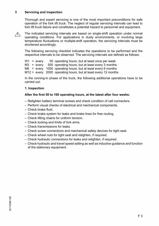
F 3
5011
8386
GB
3 Servicing and inspection
Thorough and expert servicing is one of the most important preconditions for safeoperation of the fork lift truck. The neglect of regular servicing intervals can lead tofork lift truck failure and constitutes a potential hazard to personnel and equipment.
m The indicated servicing intervals are based on single-shift operation under normaloperating conditions. For applications in dusty environments, or involving largetemperature fluctuations or multiple-shift operation, the servicing intervals must beshortened accordingly.
The following servicing checklist indicates the operations to be performed and therespective intervals to be observed. The servicing intervals are defined as follows:
W1 = every 50 operating hours, but at least once per weekM3 = every 500 operating hours, but at least every 3 monthsM6 = every 1000 operating hours, but at least every 6 monthsM12 = every 2000 operating hours, but at least every 12 months
In the running-in phase of the truck, the following additional operations have to becarried out:
1. Inspection
After the first 50 to 100 operating hours, at the latest after four weeks:
– Retighten battery terminal screws and check condition of cell connectors.– Perform visual checks of electrical and mechanical components.– Check brake fluid.– Check brake system for leaks and brake lines for free routing.– Check lifting chains for uniform tension.– Check locking and limits of fork arms.– Check transmissions for leaks.– Check screw connections and mechanical safety devices for tight seat.– Check wheel nuts for tight seat and retighten, if required.– Check hydraulic connections for leaks and retighten, if required.– Check hydraulic and travel speed setting as well as inductive guidance and function
of the stationary equipment.

5011
8386
GB
F 4
3.1 Maintenance checklist ETX ac 125/150
A The maintenance intervals refer to normal service conditions. In case of aggravated conditions, the intervals must be reduced as required.
Maintenance intervalsStandard = t W
1M3
M6
M12
Chassis/superstructure:
1.1 Check all load bearing elements for damage t1.2 Check all bolted connections t1.3 Check markings, ID plates, and warning labels for
readability and renew, if necessary t
1.4 Check safety belt for damages and secure attachment t
1.5 Check is label are present, readable, and valid t1.6 Check battery hood gas spring for function and
damage t
Drive: 2.1 Grease the bearing of the transmission t2.2 Check transmission for noise and leaks t2.3 Check the transmission oil level t2.4 Change transmission oil t
Wheels: 3.1 Check for wear and damage t3.2 Check bearing and secure attachment t
Steering 4.1 Check function and adjustment of wheel position t4.2 Check distance between guide rollers and rail guide
along the entire rail system. The play between the two guide rollers and the rails (measure across the axle) should be 0 - 5 mm. The rollers must not be jammed.
t
Brake system: 5.1 Performance and adjustment check t5.2 Check the brake linings for wear t5.3 Check brake mechanism and adjust and grease, if
required t
5.4 Check brake lines and connections t5.5 Check brake fluid t5.6 Changing the brake fluid t
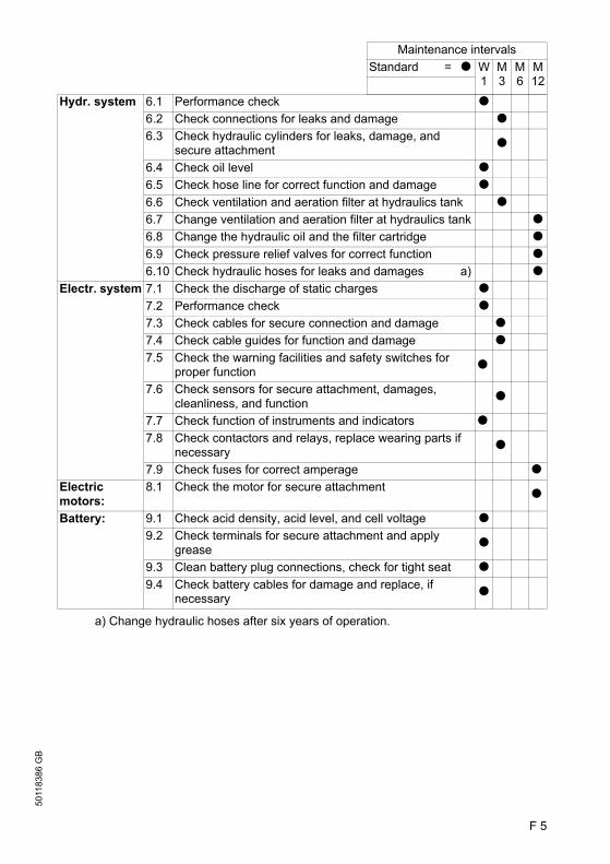
F 5
5011
8386
GB
a) Change hydraulic hoses after six years of operation.
Maintenance intervalsStandard = t W
1M3
M6
M12
Hydr. system 6.1 Performance check t6.2 Check connections for leaks and damage t6.3 Check hydraulic cylinders for leaks, damage, and
secure attachment t
6.4 Check oil level t6.5 Check hose line for correct function and damage t6.6 Check ventilation and aeration filter at hydraulics tank t6.7 Change ventilation and aeration filter at hydraulics tank t6.8 Change the hydraulic oil and the filter cartridge t6.9 Check pressure relief valves for correct function t6.10 Check hydraulic hoses for leaks and damages a) t
Electr. system 7.1 Check the discharge of static charges t7.2 Performance check t7.3 Check cables for secure connection and damage t7.4 Check cable guides for function and damage t7.5 Check the warning facilities and safety switches for
proper function t
7.6 Check sensors for secure attachment, damages, cleanliness, and function t
7.7 Check function of instruments and indicators t7.8 Check contactors and relays, replace wearing parts if
necessary t
7.9 Check fuses for correct amperage tElectric motors:
8.1 Check the motor for secure attachment t
Battery: 9.1 Check acid density, acid level, and cell voltage t9.2 Check terminals for secure attachment and apply
grease t
9.3 Clean battery plug connections, check for tight seat t9.4 Check battery cables for damage and replace, if
necessary t

5011
8386
GB
F 6
Maintenance intervalsStandard = t W
1M3
M6
M12
Lifting device 10.1 Apply grease to rollers and lateral running surfaces of the guide rollers in the lifting mast profiles and in the swivel/traverse unit.
f Attention: Danger of falling down!t
10.2 Check lifting mast attachment t10.3 Check the lifting chains and chain guide for wear, adjust
and grease t
10.4 Perform sight check of rollers, sliding elements, and stops t
10.5 Check lifting mast bedding t10.6 Check fork arms and fork arm carriage for wear and
damage t
10.7 Grease all lubrication locations of the guide rollers of the lifting mast t
Load-carrying attachments
11.1 Performance check t11.2 Check secure attachment at truck and supporting
elements t
11.3 Check bearings, guides, and stops for wear and damage; clean and grease, also grease the toothed racks
t
11.4 Check eccentric bolt and glide bar adjustment at swivel/traverse frame and re-adjust, if necessary. t
11.5 Grease guide rollers and swivel bearing of the swivel/traverse fork. t
Lubrication: 12.1 Grease the industrial truck in accordance with the lubrication schedule t
General measure-ments:
13.1 Check the electrical system for a grounding fault t13.2 Check travel speed and braking distance t13.3 Check lifting and lowering speed t13.4 Check cut-off functions t13.5 IG: Measure current in guide wire and adjust, if
necessary t
13.6 Check travel behaviour on IG wire and maximum deviation and re-adjust, if necessary t
13.7 Check tracking-in mode on the IG wire for aisle tracking t13.8 Check EMERGENCY STOP function of IG t
Demonstra-tion:
14.1 Perform trial run under nominal load t14.2 Upon completion of servicing operations, demonstrate
the vehicle to the person responsible t
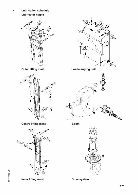
F 7
5011
8386
GB
4 Lubrication schedule Lubricator nipple
Outer lifting mast Load-carrying unit
Centre lifting mast Boom
Inner lifting mast Drive system
F 7
5011
8386
GB
4 Lubrication schedule Lubricator nipple
Outer lifting mast Load-carrying unit
Centre lifting mast Boom
Inner lifting mast Drive system
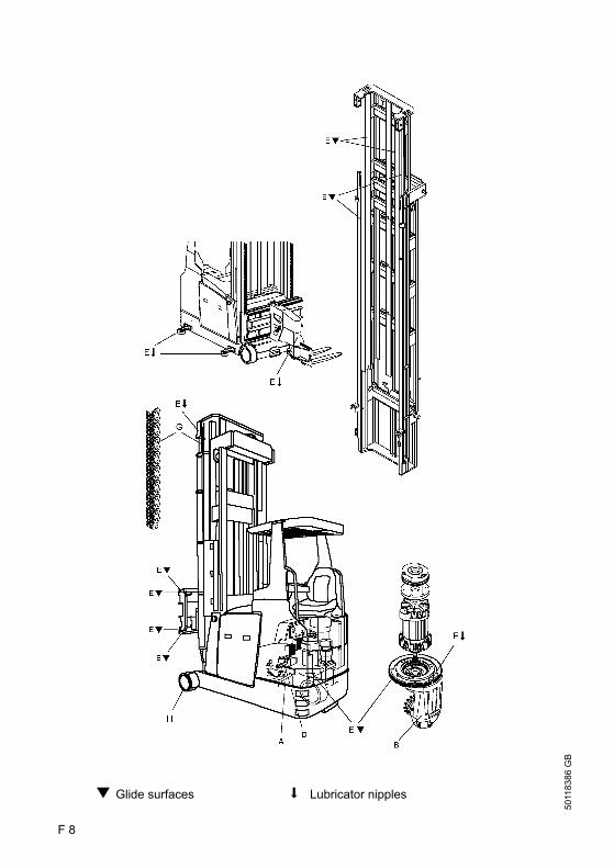
5011
8386
GB
F 8
g Glide surfaces s Lubricator nipples
5011
8386
GB
F 8
g Glide surfaces s Lubricator nipples
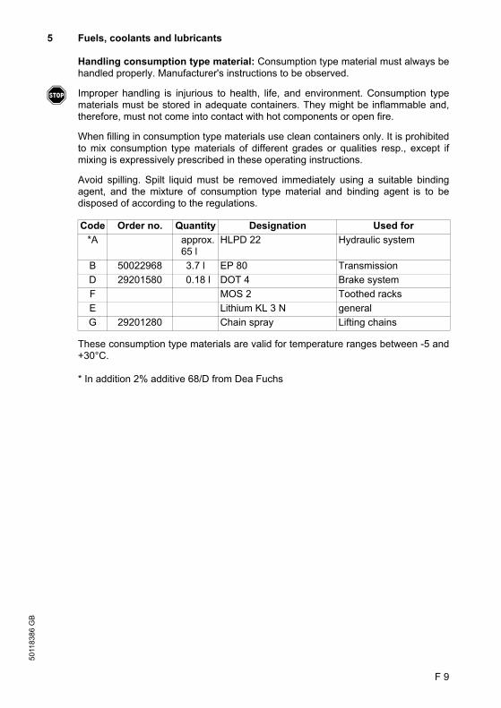
F 9
5011
8386
GB
5 Fuels, coolants and lubricants
Handling consumption type material: Consumption type material must always behandled properly. Manufacturer's instructions to be observed.
f Improper handling is injurious to health, life, and environment. Consumption typematerials must be stored in adequate containers. They might be inflammable and,therefore, must not come into contact with hot components or open fire.
When filling in consumption type materials use clean containers only. It is prohibitedto mix consumption type materials of different grades or qualities resp., except ifmixing is expressively prescribed in these operating instructions.
Avoid spilling. Spilt liquid must be removed immediately using a suitable bindingagent, and the mixture of consumption type material and binding agent is to bedisposed of according to the regulations.
These consumption type materials are valid for temperature ranges between -5 and+30°C.
* In addition 2% additive 68/D from Dea Fuchs
Code Order no. Quantity Designation Used for*A approx.
65 lHLPD 22 Hydraulic system
B 50022968 3.7 l EP 80 TransmissionD 29201580 0.18 l DOT 4 Brake systemF MOS 2 Toothed racksE Lithium KL 3 N generalG 29201280 Chain spray Lifting chains

5011
8386
GB
F 10
6 Description of servicing and maintenance operations
6.1 Prepare the truck for the servicing and maintenance operations
All required safety measures must be taken to prevent any accidents in the course ofthe servicing and maintenance operations. The following preparatory operationsmust be performed:
– Park and lock the truck securely (see chapter E).– Unplug the battery connector, thus securing the industrial truck against accidental
operation.– When work has to be performed under the jacked-up industrial truck, suitable
measures must be taken to prevent any dropping, tilting or slipping of the truck.
f When lifting the industrial truck, the instructions contained in chapter “Transportationand commissioning” have to be observed (refer to chapter C).
6.2 Secure the load-carrying unit
The load-carrying unit can be secured inelevated position.
– Lift the load-carrying unit until theinner mast (1) is positioned above thebeam of the load-carrying unit safetydevice.
– Screw out fastening screw (4) andremove safety bolt (3) from beam (2)at main mast (5).
– Attach safety bolt to the vertical hole ofthe beam and screw on tightly.
– Lower the driver position carrier slowlyas far until the inner mast is seated onthe safety bolt.
6.3 Cleaning the lifting chains
m It is important to keep all lifting chainsand pivots clean and lubricated at alltimes. Lifting chains are safetyelements.
Chains must not be excessively dirty.For cleaning, only paraffin derivatives(such as, for example, kerosene ordiesel fuel) may be used.Never clean chains with steam jetpressure washer, cold cleaner, orchemical cleaners.
1
2
3
4
5
1
2
4

F 11
5011
8386
GB
6.4 Inspection of lifting chains
Improper wear and external damages:
According to the official regulations a chain is regarded as worn out, if it has elongatedby more than 3% in the section where it runs around the deflection pulley. For safetyreason we recommend to replace a chain when it has elongated by 2%.
A chain should also be changed immediately when external damages are detected,as such damages result in fatigue fractures after a certain time period.
m If the industrial truck is equipped with two lifting chains, always both chains must bereplaced. Only then the equal load distribution to both chains can be guaranteed.When replacing chains, also the connection bolts between chain anchor and chainmust be renewed. As a rule, only original parts may be used.
6.5 Chain repair
Also when repairing chains, only original parts may be used. The rivet heads must beground off before dismounting. In this way damages caused by driving the boltthrough the intermediate plate resp. the inner link in the hole section are avoided.Removed bolts and plates must not be reused.
6.6 Changing gear oil
m Absolute care must be taken that the oil cannot be spilled into the sewer or onto thesoil. Waste oil must be securely stored until its proper disposal.
Draining the oil:
– Place an oil pan under thetransmission.
– Open oil drain plug (7) on the bottomside of the transmission and allow theoil to drain.
Refilling oil:
– Screw in oil drain plug (7) and tighten.– Open oil check and filler plug (6) at the
top side of the transmission.– Fill new transmission oil up to the oil
check opening.– Screw in oil check and filler plug (6).
A Because of the proper disposal andpossibly required special tools and skillsthe transmission and hydraulic oilchange as well as changing brake fluid and filters should be performed by thecustomer service.
6
7
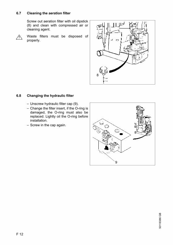
5011
8386
GB
F 12
6.7 Cleaning the aeration filter
Screw out aeration filter with oil dipstick(8) and clean with compressed air orcleaning agent.
m Waste filters must be disposed ofproperly.
6.8 Changing the hydraulic filter
– Unscrew hydraulic filter cap (9).– Change the filter insert, if the O-ring is
damaged, the O-ring must also bereplaced. Lightly oil the O-ring beforeinstallation.
– Screw in the cap again.
8
9

F 13
5011
8386
GB
6.9 Hydraulic oil
– Prepare the truck for the servicing and maintenance operations.
m Absolute care must be taken that the oil cannot be spilled into the sewer or onto thesoil. Waste oil must be securely stored until its proper disposal.
Draining the oil:
Suck off the hydraulic oil after removingaeration filter (8). If this method cannotbe used, the hydraulic oil can be drainedafter unscrewing the oil drain plug at thebottom of the hydraulic tank.
Refilling oil:
Screw in the oil drain plug again. Fill innew hydraulic oil until the upper mark(max.) at oil dipstick (10). Screw on theaeration filter again.
Checking the hydraulic oil level:
With the lifting mast completely lowered, check whether the hydraulic oil level isbetween the min. and max. marks of oil dipstick(10).If this is not the case, new hydraulic oil must be refilled.
108

5011
8386
GB
F 14
6.10 Checking the brake fluid
f Brake fluid is poisonous and musttherefore be stored in closed originalcontainers. Moreover it should be notedthat brake fluid is corrosive on the truck’spaint.
The factory-filled brake fluid must beexchanged at least after two years, as itchanges in the course of time and losesits original properties.
The brake fluid reservoir (11) is locatedin the rear of the truck and can beaccessed after removing the cover. Thereservoir should always be filled up to2 cm below the reservoir cap.Only use the prescribed fluid.It must be guaranteed at all times thatthe entire brake system has no leaks.
6.11 Restrain safety belt service
The driver must check condition and correct operation of the safety restraint belt ondaily basis before using the industrial truck. Early detection of malfunctions is onlypossible through regular checks.
– Pull out belt completely and check for unravelling.– Check the function of the belt buckle for correct retraction of the belt into the
retractor– Check cover for damage
Testing the automatic blocking retractor:
– Park the industrial truck on a horizontal surface– Pull out the belt with a jerk
m The automatic blocking system must lock the belt in the retractor.
f Do not operate the industrial truck when the safety restraint belt is defective; have thebelt exchanged immediately!
6.12 Electrical fuses
f Electrical fuses must only be checked and replaced by authorised specialists.
11

F 15
5011
8386
GB
6.13 Recommissioning the truck
Recommissioning of the truck following the performance of cleaning or maintenancework is permitted only after the following operations have been performed:
– Check the horn for proper functioning.– Check the master switch for correct functioning.– Check the brake for correct functioning.
7 Decommissioning the fork lift truck
If the fork lift truck is to be decommissioned for more than two months, it must beparked in a frost-free and dry location and all measures to be taken before, during andfollowing decommissioning must be performed as detailed below.
m During decommissioning, the fork lift truck must be jacked up, ensuring that thewheels are clear of the ground. Only this measure will ensure that wheels and wheelbearings do not suffer damage.
If the fork lift truck is to be decommissioned for more than 6 months, additionalmeasures must be discussed with the Service Department of the manufacturer.
7.1 Operations to be performed prior to decommissioning
– Thoroughly clean the fork lift truck.– Check the brakes for correct function.– Check the hydraulic oil level and top up if required (refer to chapter F).– Apply a thin film of oil or grease to all parts not protected by a paint coating.– Grease the fork lift truck as detailed in the lubrication chart (refer to chapter F).– Recharge the battery (refer to chapter D).– Disconnect and clean the battery. Apply pole grease to the battery poles.
A In addition to this, all instructions given by the battery supplier must be observed.
– Spray all exposed electrical contacts with a suitable contact spray.
7.2 Measures to be taken during decommissioning
Every 2 months:
– Recharge the battery (refer to chapter D).
m Battery-operated fork lift trucks:Regular recharging of the battery is very important; otherwise, exhaustive depletionof the battery caused by self-discharging would occur. Owing to sulfatisation, this willresult in the destruction of the battery.

5011
8386
GB
F 16
7.3 Recommissioning the truck
– Thoroughly clean the fork lift truck.– Lubricate the fork lift truck according to the lubrication chart (refer to chapter F).– Clean the battery. Grease the pole screws using pole grease and reconnect the
battery.– Recharge the battery (refer to chapter D).– Check if the gear oil contains condensed water and change if required.– Check if the hydraulic oil contains condensed water and change if required.– Start up the fork lift truck (refer to chapter E).
A Battery-operated fork lift trucks:If switching troubles are experienced in the electric system, spray the exposedcontacts with contact spray and remove any oxide layer on the contacts of theoperating controls by repeated operation.
f Perform several brake tests immediately after recommissioning the truck.
8 Safety checks to be performed at regular intervals and following any untowardincidents (D: Accident prevention check according to VBG 36)
At least once yearly, or after any untoward incident, the fork lift truck has to bechecked by a qualified inspector. The inspector must assess the condition of the truckfrom a standpoint purely concerned with safety aspects, uninfluenced by anycompany or economic circumstances. The inspector must be adequately informedand experienced to be able to assess the condition of the fork lift truck and theeffectiveness of the safety installations based on the technical rules and principlesgoverning the inspection of fork lift trucks.
The inspection must comprise a comprehensive check of the technical condition ofthe fork lift truck with regard to accident prevention aspects. Apart from this, the forklift truck must be thoroughly inspected for damage possibly caused by incorrect useof the fork lift truck. The inspection results must be recorded in an inspection reportwhich must be kept available for a period spanning at least the next two inspectionintervals.
The user has to ensure that all defects are eliminated without delay.
A The manufacturer has set up a special safety service with specially qualified staff. Asvisual proof that the fork lift truck has passed the safety inspection, a plaque is affixedto it. This plaque indicates in which month of which year the next test will be due.