Embed Size (px)
Citation preview
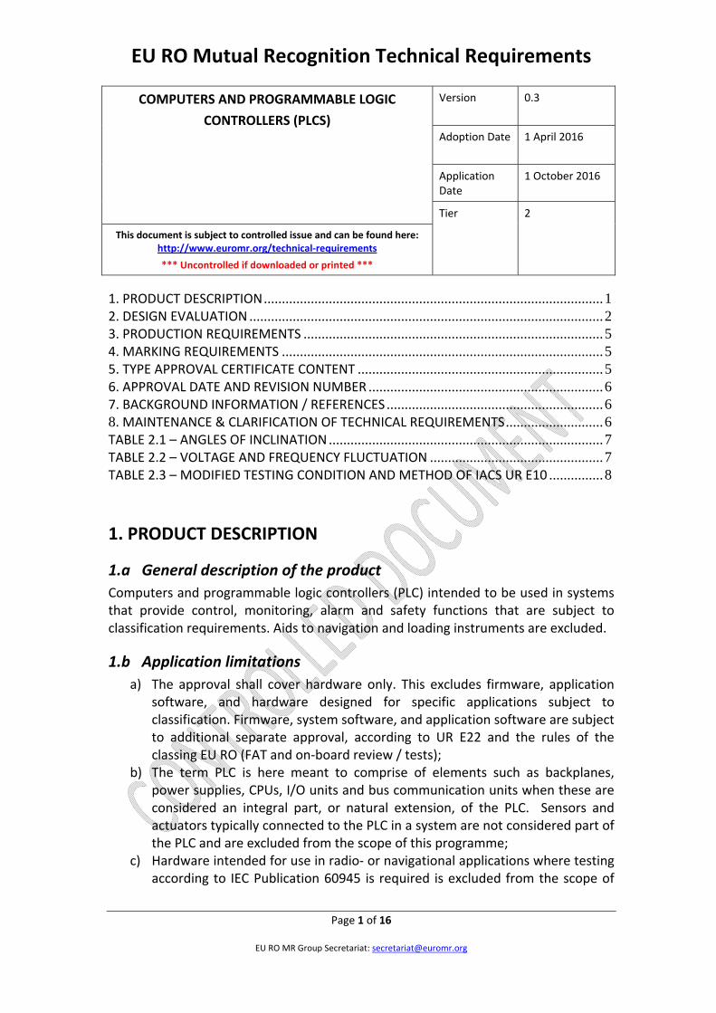
EU RO Mutual Recognition Technical Requirements
COMPUTERS AND PROGRAMMABLE LOGIC
CONTROLLERS (PLCS)
Version 0.3
Adoption Date 1 April 2016
Application Date
1 October 2016
Tier 2
This document is subject to controlled issue and can be found here: http://www.euromr.org/technical‐requirements
*** Uncontrolled if downloaded or printed ***
Page 1 of 16
EU RO MR Group Secretariat: [email protected]
1. PRODUCT DESCRIPTION .............................................................................................. 1 2. DESIGN EVALUATION .................................................................................................. 2 3. PRODUCTION REQUIREMENTS ................................................................................... 5 4. MARKING REQUIREMENTS ......................................................................................... 5 5. TYPE APPROVAL CERTIFICATE CONTENT .................................................................... 5 6. APPROVAL DATE AND REVISION NUMBER ................................................................. 6 7. BACKGROUND INFORMATION / REFERENCES ............................................................ 6 8. MAINTENANCE & CLARIFICATION OF TECHNICAL REQUIREMENTS ........................... 6 TABLE 2.1 – ANGLES OF INCLINATION ............................................................................ 7 TABLE 2.2 – VOLTAGE AND FREQUENCY FLUCTUATION ................................................ 7 TABLE 2.3 – MODIFIED TESTING CONDITION AND METHOD OF IACS UR E10 ............... 8
1. PRODUCT DESCRIPTION
1.a General description of the product
Computers and programmable logic controllers (PLC) intended to be used in systems that provide control, monitoring, alarm and safety functions that are subject to classification requirements. Aids to navigation and loading instruments are excluded.
1.b Application limitations
a) The approval shall cover hardware only. This excludes firmware, application software, and hardware designed for specific applications subject to classification. Firmware, system software, and application software are subject to additional separate approval, according to UR E22 and the rules of the classing EU RO (FAT and on‐board review / tests);
b) The term PLC is here meant to comprise of elements such as backplanes, power supplies, CPUs, I/O units and bus communication units when these are considered an integral part, or natural extension, of the PLC. Sensors and actuators typically connected to the PLC in a system are not considered part of the PLC and are excluded from the scope of this programme;
c) Hardware intended for use in radio‐ or navigational applications where testing according to IEC Publication 60945 is required is excluded from the scope of

EU RO Mutual Recognition Technical Requirements
COMPUTERS AND PROGRAMMABLE LOGIC
CONTROLLERS (PLCS)
Version 0.3
Adoption Date 1 April 2016
Application Date
1 October 2016
Tier 2
This document is subject to controlled issue and can be found here: http://www.euromr.org/technical‐requirements
*** Uncontrolled if downloaded or printed ***
Page 2 of 16
EU RO MR Group Secretariat: [email protected]
this programme. E.g. use in systems covered by the Marine Equipment Directive.
1.c Intended use
Control, monitoring, alarm, and safety functions provided by computer / PLC based systems subject to classification requirements.
1.d System context
Application of the control, monitoring, alarm, and safety systems are subject for approval of the individual EU RO classing the vessel.
2. DESIGN EVALUATION
2.a Engineering evaluation requirements
2.a i. Technical Requirements
Ambient Conditions
a) The ambient condition given in Table 2.1 shall be applied to the design, selection and arrangement of electrical installations in order to ensure their proper operation;
b) Electrical equipment shall be suitable for operations up to 55°C, regardless of location;
c) Electrical equipment shall be designed to withstand any vibrations that occur under normal conditions;
d) Electrical equipment, or the installation of electrical equipment, shall be provided with a degree of protection appropriate to the location, as a minimum the requirements of IEC Publication 60092‐504. Electrical equipment shall have a minimum degree of protection equivalent to IP20, regardless of location or installation.

EU RO Mutual Recognition Technical Requirements
COMPUTERS AND PROGRAMMABLE LOGIC
CONTROLLERS (PLCS)
Version 0.3
Adoption Date 1 April 2016
Application Date
1 October 2016
Tier 2
This document is subject to controlled issue and can be found here: http://www.euromr.org/technical‐requirements
*** Uncontrolled if downloaded or printed ***
Page 3 of 16
EU RO MR Group Secretariat: [email protected]
Voltage and Frequency
e) Electrical equipment supplied from main and emergency switchboards shall be
designed and manufactured so that it is capable of operating satisfactorily under the
normally occurring voltage and frequency fluctuations. Such electrical equipment
shall operate satisfactorily under those fluctuations in voltage and frequency that
are given in Table 2.2. Any special systems, e.g. electronic circuits, whose functions
cannot operate satisfactorily, within the limits given in this table, shall be supplied by
suitable means, i.e. through stabilized supply.
Construction, Materials, Installations, etc.
f) All electrical equipment shall be constructed and installed so as not to cause injury when handled and touched in a normal manner;
g) Insulating materials and insulated windings shall be resistant to moisture, sea air and oil vapours;
h) Bolts, nuts, pins, screws, terminals, studs, springs and such other small parts shall be made of corrosion resistant material or to be suitably protected against corrosion.
2.a.ii. Technical documents to be submitted:
IMPORTANT: The English Language shall be used for all submitted documents.
a) Drawings, schematics and functional description necessary to describe all parts of the equipment. The functional description can be in the form of user manuals, installation manuals, etc. as relevant;
b) Drawings and product specification of physical/electrical and logical interfaces including signal format, converters, I/O‐cards, protective circuitry, data protocol, cabling, and required configuration;
c) Hardware, firmware and system software information necessary to identify the equipment under test. (Application software shall not be reviewed in the framework of type approval of computers / PLC);
d) Functional tests that are required by tests according to Table 2.3 have to be defined. The tests shall be suitable to monitor all types of signal interfaces, inputs and outputs reliably. The necessary application program, wiring and

EU RO Mutual Recognition Technical Requirements
COMPUTERS AND PROGRAMMABLE LOGIC
CONTROLLERS (PLCS)
Version 0.3
Adoption Date 1 April 2016
Application Date
1 October 2016
Tier 2
This document is subject to controlled issue and can be found here: http://www.euromr.org/technical‐requirements
*** Uncontrolled if downloaded or printed ***
Page 4 of 16
EU RO MR Group Secretariat: [email protected]
description of the functional verification should be part of the submitted test program and test reports; Note: The Manufacturer may submit the draft test programmes to the RO for verification prior to the commencement of any environmental & performance type testing. A certificate of accreditation for the selected laboratory/ laboratories) is generally a demand.
End of Note
e) Environmental‐ and Performance type test reports; f) Special operational limitations, if any; g) Documentation about the Production quality assurance system; h) Product marking.
2.b Type testing requirements
a) Tests shall be carried out in accordance with the testing condition and method of the latest revision of IACS UR E10 with modifications given in Table 2.3 in the presence of the EU RO’s surveyor, and they shall be proven to satisfy the criteria of the last revision of IACS UR E10 and Table 2.3.
b) Tests shall be carried out in the presence of the EU RO Surveyor. In cases where the tests are conducted at Nationally Accredited Laboratories, the presence of the EU RO surveyor may be omitted†;
c) All type testing shall be documented in accordance with ISO/IEC 17025; d) It is the manufacturers’ responsibility to make sure that the type testing is
performed in accordance with approved test programme so being acceptable to the EU RO;
e) Test specimens shall be taken from the production line or from stocks†. f) All tests are normally to be carried out on the same unit. Using different units
for the different type of tests is acceptable provided that all EMC tests are carried out on the same unit (1), and all environmental tests are carried out on the same unit (2).
† For further clarification of witnessing of tests and sampling the test specimen(s), refer to paragraphs 6, 7 and 8 of the EU RO “Design Evaluation Scheme" procedure

EU RO Mutual Recognition Technical Requirements
COMPUTERS AND PROGRAMMABLE LOGIC
CONTROLLERS (PLCS)
Version 0.3
Adoption Date 1 April 2016
Application Date
1 October 2016
Tier 2
This document is subject to controlled issue and can be found here: http://www.euromr.org/technical‐requirements
*** Uncontrolled if downloaded or printed ***
Page 5 of 16
EU RO MR Group Secretariat: [email protected]
(Appendix V of EU RO Framework Document for the Mutual Recognition of Type Approval found on http://www.euromr.org/Guidance%20for%20Mutual%20Recognition)
3. PRODUCTION REQUIREMENTS Refer to EU RO “Product Quality Assurance (PQA)" procedure (Appendix VI of EU RO Framework Document for the Mutual Recognition of Type Approval).
4. MARKING REQUIREMENTS Manufacturers of the approved equipment are, in principle, to mark the product before shipment for identification of approved equipment as per referenced standard. In addition, and as a minimum, the following items to be marked at the suitable place:
a) Manufacturer’s name or equivalent; b) Type No. or symbol; c) Serial No. and date of manufacture; d) Particulars or ratings.
5. TYPE APPROVAL CERTIFICATE CONTENT The EU RO MR Type Approval Certificate shall contain the minimum information as defined in the “EU RO Framework Document for the Mutual Recognition of Type Approval” ‐ see Appendix I EU RO MR Type Approval Certificate Information.
The following information is specifically applicable to products relevant to this technical requirement and shall be included on the relevant EU RO MR Type Approval Certificate:
a) Hardware, firmware, system software names / versions.

EU RO Mutual Recognition Technical Requirements
COMPUTERS AND PROGRAMMABLE LOGIC
CONTROLLERS (PLCS)
Version 0.3
Adoption Date 1 April 2016
Application Date
1 October 2016
Tier 2
This document is subject to controlled issue and can be found here: http://www.euromr.org/technical‐requirements
*** Uncontrolled if downloaded or printed ***
Page 6 of 16
EU RO MR Group Secretariat: [email protected]
6. APPROVAL DATE AND REVISION NUMBER Date Revision Comment 2013‐04‐30 0.0 Accepted by Advisory Board
2014‐01‐31 0.1 CRF008 ‐ Reference to EU RO Framework Document for the Mutual Recognition of Type Approval added.
2015‐01‐31 0.2 CRF018 – Revision to par. 2.a.ii ‐ Test results to be in English; CRF020 – Revision to par. 5 ‐ ‘Type Approval Certificate Content’.
1 April 2016 0.3 CRF025 – Updated to new MR TR document format incl. par. 8; CRF026/026a – Witness testing & control of test specimen; CRF028 – addition of 6 month application clause.
7. BACKGROUND INFORMATION / REFERENCES a) EU RO Framework Document for the Mutual Recognition of Type
Approval;
b) IACS UR E10 “Test specification for type approval”; c) IEC 60092‐504 “Electrical installations in ships – Special features, Control
and instrumentation”; d) IEC 60945 “Maritime Navigation and Radio communication Equipment
and Systems – General Requirements”; e) IEC 60533 “Electrical and electronic installations in ships –
Electromagnetic compatibility”; f) IACS UR E22 "On Board Use and Application of Programmable Electronic
Systems".
8. MAINTENANCE / CLARIFICATION OF TECHNICAL REQUIREMENTS
Anyone wishing to propose changes to this document or request clarification of technical issues should contact the EU RO MR Group Secretariat in the first instance: [email protected]. Review and approval of change requests shall follow the EU RO MR Maintenance Process detailed in the EU RO Framework Document for the Mutual Recognition of Type Approval: http://www.euromr.org/Guidance%20for%20Mutual%20Recognition.

EU RO Mutual Recognition Technical Requirements
COMPUTERS AND PROGRAMMABLE LOGIC
CONTROLLERS (PLCS)
Version 0.3
Adoption Date 1 April 2016
Application Date
1 October 2016
Tier 2
This document is subject to controlled issue and can be found here: http://www.euromr.org/technical‐requirements
*** Uncontrolled if downloaded or printed ***
Page 7 of 16
EU RO MR Group Secretariat: [email protected]
Table 2.1 – Angles of Inclination
Static inclination Dynamic inclination
22.5° (Note 1) 22.5° (Note 1)
Note 1: In ships carrying liquefied gases in bulk and ships carrying dangerous chemicals in bulk, emergency
power supplies shall remain operable with the ship flooded to a final athwart ships inclination up to a maximum of 30°. In this case the test level has to be named on the certificate.
Table 2.2 – Voltage and Frequency Fluctuation (a) Voltage and frequency fluctuations for a.c. distribution systems (Note 1)
Type of fluctuation Fluctuation (Note 4)
Permanent Transient
Voltage ±10% ±20% (1.5 s duration)
Frequency ±5% ±10% (5 s duration)
(b) Voltage fluctuations for d.c. distribution systems (Note 2)
Type of fluctuation Fluctuation (Note 4)
Voltage fluctuation (Permanent) ±10%
Voltage cyclic fluctuation deviation 5%
Voltage ripple 10%
(c) Voltage fluctuations for battery systems
Systems Fluctuation (Note 4)
Components connected to the battery during charging (Note 3) +30%, ‐25%
Components not connected to the battery during charging +20%, ‐25%
All components 25% (2 s duration)
Note 1: A.C. distribution systems mean a.c. generator circuits and a.c. power circuits produced by inverters. Note 2: D.C. distribution systems mean d.c. generator circuits and d.c. power circuits produced by converters. Note 3: Different voltage fluctuations as determined by charging and discharging characteristics, including
voltage ripples from the charging devices, may be considered. Note 4: The numerical values given in the table, excluding those values for time, mean percentages of rated
values.

EU RO Mutual Recognition Technical Requirements
COMPUTERS AND PROGRAMMABLE LOGIC
CONTROLLERS (PLCS)
Version 0.3
Adoption Date 1 April 2016
Application Date
1 October 2016
Tier 2
This document is subject to controlled issue and can be found here: http://www.euromr.org/technical‐requirements
*** Uncontrolled if downloaded or printed ***
Page 8 of 16
EU RO MR Group Secretariat: [email protected]
Table 2.3 – Modified testing condition and method of IACS UR E10
NO.
TEST PROCEDURE ACC. TO:*
TEST PARAMETERS OTHER INFORMATION
*Note: indicates the testing procedure which is normally to be applied. However, equivalent testing procedure may be accepted by the individual EU RO provided that the Unified Requirements stated in the other columns are fulfilled.
1. Visual inspection ‐ ‐ − conformance to drawings, design data, marking of product
− quality of workmanship and construction
2. Performance test Manufacturer performance test programme based upon specification and relevant Rule requirements.
‐ standard atmosphere conditions ‐ temperature: 25°C ± 10°C ‐ relative humidity: 60% ± 30% ‐ air pressure: 96 kPa ± 10 kPa
- confirmation that operation is in accordance with the requirements specified for particular system or equipment;
- checking of self‐monitoring features; - checking of specified protection against
an access to the memory; - checking against effect of unerroneous
use of control elements in the case of computer systems.
3. External power supply failure
‐ ‐ 3 interruptions during 5 minutes; ‐ switching‐off time 30 s each case
- the time of 5 minutes may be exceeded if the equipment under test needs a longer time for start up, e.g. booting sequence
- for equipment which requires booting, one additional power supply interruption during booting to be performed
Verification of: - equipment behaviour upon loss and
restoration of supply; - possible corruption of programme or
data held in programmable electronic systems, where applicable.
4. Power supply variations
‐ AC SUPPLY
Combination
Voltage variation permanent
%
Frequency variation permanent
%
1 2 3 4
+10 +10 ‐10 ‐10
+5 ‐5 ‐5 +5
transient 1,5 s %
transient 5 s %
5 6
+20 ‐20
+10 ‐10
EU RO Mutual Recognition Technical Requirements
COMPUTERS AND PROGRAMMABLE LOGIC
CONTROLLERS (PLCS)
Version 0.3
Adoption Date 1 April 2016
Application Date
1 October 2016
Tier 2
This document is subject to controlled issue and can be found here: http://www.euromr.org/technical‐requirements
*** Uncontrolled if downloaded or printed ***
Page 9 of 16
EU RO MR Group Secretariat: [email protected]
NO.
TEST PROCEDURE ACC. TO:*
TEST PARAMETERS OTHER INFORMATION
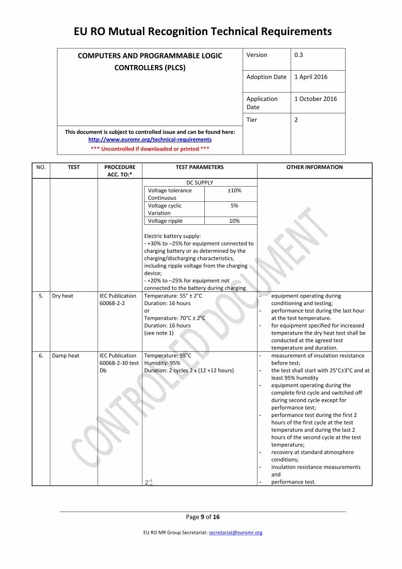
DC SUPPLY
Voltage tolerance Continuous
±10%
Voltage cyclic Variation
5%
Voltage ripple 10%
Electric battery supply: ‐ +30% to –25% for equipment connected to charging battery or as determined by the charging/discharging characteristics, including ripple voltage from the charging device; ‐ +20% to –25% for equipment not connected to the battery during charging.
5. Dry heat IEC Publication 60068‐2‐2
Temperature: 55° ± 2°C Duration: 16 hours or Temperature: 70°C ± 2°C Duration: 16 hours (see note 1)
- equipment operating during conditioning and testing;
- performance test during the last hour at the test temperature.
- for equipment specified for increased temperature the dry heat test shall be conducted at the agreed test temperature and duration.
6. Damp heat IEC Publication 60068‐2‐30 test Db
Temperature: 55°C Humidity: 95% Duration: 2 cycles 2 x (12 +12 hours)
- measurement of insulation resistance before test;
- the test shall start with 25°C±3°C and at least 95% humidity
- equipment operating during the complete first cycle and switched off during second cycle except for performance test;
- performance test during the first 2 hours of the first cycle at the test temperature and during the last 2 hours of the second cycle at the test temperature;
- recovery at standard atmosphere conditions;
- insulation resistance measurements and
- performance test. 302

EU RO Mutual Recognition Technical Requirements
COMPUTERS AND PROGRAMMABLE LOGIC
CONTROLLERS (PLCS)
Version 0.3
Adoption Date 1 April 2016
Application Date
1 October 2016
Tier 2
This document is subject to controlled issue and can be found here: http://www.euromr.org/technical‐requirements
*** Uncontrolled if downloaded or printed ***
Page 10 of 16
EU RO MR Group Secretariat: [email protected]
NO.
TEST PROCEDURE ACC. TO:*
TEST PARAMETERS OTHER INFORMATION
7. Vibration IEC Publication 60068‐2‐6 Test Fc
Hz to 13.2 Hz – amplitude ±1mm 13.2 Hz to 100 Hz – acceleration ± 0.7 g. For severe vibration conditions such as, e.g. on diesel engines, air compressors, etc.: 2.0 Hz to 25 Hz – amplitude ±1.6 mm 25.0 Hz to 100 Hz – acceleration ± 4.0 g. Note: More severe conditions may exist for example on exhaust manifolds or fuel oil injection systems of diesel engines. For equipment specified for increased vibration levels the vibration test shall be conducted at the agreed vibration level, frequency range and duration. Values may be required to be in these cases 40 Hz to 2000 Hz ‐ acceleration ± 10.0g at 600°C, duration 90 min.
- duration in case of no resonance condition 90 minutes at 30 Hz;
- duration at each resonance frequency
at which Q≥ 2 is recorded ‐ 90 minutes;
- during the vibration test, performance tests shall be carried out;
- tests to be carried out in three mutually perpendicular planes;
- Q should not exceed 5, - mechanical resonances with
amplification greater than 10 will not be accepted.
- where sweep test shall be carried out instead of the discrete frequency test and a number of resonant frequencies is detected close to each other, duration of the test shall be 120 min. Sweep over a restricted frequency range between 0.8 and 1.2 times the critical frequencies can be used where appropriate.
Note: Critical frequency is a frequency at which the equipment being tested may exhibit: - malfunction and/or performance
deterioration - mechanical resonances and/or other
response effects occur, e.g. chatter

EU RO Mutual Recognition Technical Requirements
COMPUTERS AND PROGRAMMABLE LOGIC
CONTROLLERS (PLCS)
Version 0.3
Adoption Date 1 April 2016
Application Date
1 October 2016
Tier 2
This document is subject to controlled issue and can be found here: http://www.euromr.org/technical‐requirements
*** Uncontrolled if downloaded or printed ***
Page 11 of 16
EU RO MR Group Secretariat: [email protected]
NO.
TEST PROCEDURE ACC. TO:*
TEST PARAMETERS OTHER INFORMATION
8. Inclination Publication IEC 60092‐504
Static 22.5° Dynamic 22.5°
a) inclined to the vertical at an angle of at least 22.5°
b) inclined to at least 22.5° on the other side of the vertical and in the same plane as in (a),
c) inclined to the vertical at an angle of at least 22.5° in plane at right angles to that used in (a),
d) inclined to at least 22.5° on the other side of the vertical and in the same plane as in (c).
Note: The period of testing in each position should be sufficient to fully evaluate the behaviour of the equipment. Using the directions defined in a) to d) above, the equipment shall be rolled to an angle of 22.5° each side of the vertical with a period of 10 seconds. The test in each direction shall be carried out for not less than 15 minutes. On ships for the carriage of liquified gases and chemicals, the emergency power supply shall remain operational with the ship flooded up to a maximum final athwart ship inclination of 30°. Note: These inclination tests are normally not required for equipment with no moving parts.
9. Insulation resistance
Rated supply voltage Un (V)
Test voltage Un (V)
Min. insulation resistance
before test M ohms
after test M ohms
Un ≤ 65 2 x Un min. 24V
10 1.0
Un > 65 500 100 10
- for high voltage equipment, reference is made to UR E11.
- insulation resistance test shall be carried out before and after: damp heat test, cold test, salt mist test and high voltage test;
- between all phases and earth; and where appropriate, between the phases.
Note: Certain components e.g. for EMC protection may be required to be disconnected for this test.

EU RO Mutual Recognition Technical Requirements
COMPUTERS AND PROGRAMMABLE LOGIC
CONTROLLERS (PLCS)
Version 0.3
Adoption Date 1 April 2016
Application Date
1 October 2016
Tier 2
This document is subject to controlled issue and can be found here: http://www.euromr.org/technical‐requirements
*** Uncontrolled if downloaded or printed ***
Page 12 of 16
EU RO MR Group Secretariat: [email protected]
NO.
TEST PROCEDURE ACC. TO:*
TEST PARAMETERS OTHER INFORMATION
10. High voltage
Rated voltage Un (V)
Test voltage (A.C. voltage 50 or 60Hz) (V)
Up to 65 2 x Un + 500
66 to 250 1500
251 to 500 2000
501 to 690 2500
- for high voltage equipment, reference is made to UR E11.
- separate circuits shall be tested against each other and all circuits connected with each other tested against earth;
- printed circuits with electronic components may be removed during the test;
- period of application of the test voltage: 1 minute
11. Cold IEC Publication 60068‐2‐1
Temperature: +5°C ± 3°C Duration: 2 hours or Temperature: –25°C ± 3°C Duration: 2 hours (see note 2)
- initial measurement of insulation resistance;
- equipment not operating during conditioning and testing except for performance test;
- performance test during the last hour at the test temperature;
- insulation resistance measurement and the performance test after recovery
12. Salt mist IEC Publication 60068‐2‐52 Test Kb
Four spraying periods with a storage of 7 days after each
- initial measurement of insulation resistance and initial performance test;
- equipment not operating during conditioning;
- performance test on the 7th day of each storage period;
- insulation resistance measurement and performance test 4 to 6h after recovery. (see Note 3)
- on completion of exposure, the equipment shall be examined to verify that deterioration or corrosion (if any) is superficial in nature.
13. Electrostatic discharge
IEC 61000‐4‐2 Contact discharge: 6kV Air discharge: 8kV Interval between single discharges: 1 sec. No. of pulses: 10 per polarity According to test level 3.
- to simulate electrostatic discharge as may occur when persons touch the appliance;
- the test shall be confined to the points and surfaces that can normally be reached by the operator;
- Performance Criterion B (See Note 4).
EU RO Mutual Recognition Technical Requirements
COMPUTERS AND PROGRAMMABLE LOGIC
CONTROLLERS (PLCS)
Version 0.3
Adoption Date 1 April 2016
Application Date
1 October 2016
Tier 2
This document is subject to controlled issue and can be found here: http://www.euromr.org/technical‐requirements
*** Uncontrolled if downloaded or printed ***
Page 13 of 16
EU RO MR Group Secretariat: [email protected]
NO.
TEST PROCEDURE ACC. TO:*
TEST PARAMETERS OTHER INFORMATION
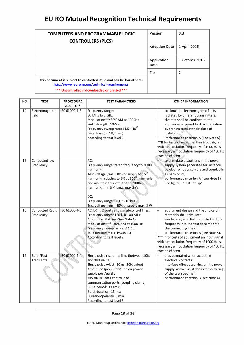
14. Electromagnetic field
IEC 61000‐4‐3 Frequency range: 80 MHz to 2 GHz Modulation**: 80% AM at 1000Hz Field strength: 10V/m Frequency sweep rate: ≤1.5 x 10
‐3 decades/s (or 1%/3 sec) According to test level 3.
- to simulate electromagnetic fields radiated by different transmitters;
- the test shall be confined to the appliances exposed to direct radiation by transmitters at their place of installation.
- Performance criterion A (See Note 5) **If for tests of equipment an input signal with a modulation frequency of 1000 Hz is necessary a modulation frequency of 400 Hz may be chosen.
15. Conducted low Frequency
AC: Frequency range: rated frequency to 200th harmonic; Test voltage (rms): 10% of supply to 15
th harmonic reducing to 1% at 100
th harmonic and maintain this level to the 200th harmonic, min 3 V r.m.s, max 2 W. DC: Frequency range: 50 Hz ‐ 10 kHz; Test voltage (rms): 10% of supply max. 2 W
- to stimulate distortions in the power supply system generated for instance, by electronic consumers and coupled in as harmonics;
- performance criterion A ( see Note 5). - See figure ‐ “Test set‐up”
16. Conducted Radio Frequency
IEC 61000‐4‐6 AC, DC, I/O ports and signal/control lines: Frequency range: 150 kHz ‐ 80 MHz Amplitude: 3 V rms (See Note 6) Modulation ***: 80% AM at 1000 Hz Frequency sweep range: ≤ 1.5 x 10‐3 decades/s (or 1%/3sec.) According to test level 2
- equipment design and the choice of materials shall stimulate electromagnetic fields coupled as high frequency into the test specimen via the connecting lines.
- performance criterion A (see Note 5). *** If for tests of equipment an input signal with a modulation frequency of 1000 Hz is necessary a modulation frequency of 400 Hz may be chosen.
17. Burst/Fast Transients
IEC 61000‐4‐4 Single pulse rise time: 5 ns (between 10% and 90% value) Single pulse width: 50 ns (50% value) Amplitude (peak): 2kV line on power supply port/earth; 1kV on I/O data control and communication ports (coupling clamp) Pulse period: 300 ms; Burst duration: 15 ms; Duration/polarity: 5 min According to test level 3.
- arcs generated when actuating electrical contacts;
- interface effect occurring on the power supply, as well as at the external wiring of the test specimen;
- performance criterion B (see Note 4).

EU RO Mutual Recognition Technical Requirements
COMPUTERS AND PROGRAMMABLE LOGIC
CONTROLLERS (PLCS)
Version 0.3
Adoption Date 1 April 2016
Application Date
1 October 2016
Tier 2
This document is subject to controlled issue and can be found here: http://www.euromr.org/technical‐requirements
*** Uncontrolled if downloaded or printed ***
Page 14 of 16
EU RO MR Group Secretariat: [email protected]
NO.
TEST PROCEDURE ACC. TO:*
TEST PARAMETERS OTHER INFORMATION
18. Surge immunity IEC 61000‐4‐5 Open‐circuit voltage: Pulse rise time: 1.2 μs ( front time) Pulse width: 50 μs (time to half value) Amplitude (peak): 1kV line/earth; 0.5kV line/line Short‐circuit current: Pulse rise time: 8 µs (front time) Pulse width: 20 µs (time to half value) Repetition rate: ≥ 1 pulse/min No of pulses: 5 per polarity Application: continuous According to test level 2.
- interference generated for instance, by switching “ON” or “OFF” high power inductive consumers;
- test procedure in accordance with figure 10 of the standard for equipment where power and signal lines are identical;
- performance criterion B (see Note 4).
19. Radiated Emission
CISPR 16‐1, 16‐2 For equipment installed in the bridge and deck zone.
Frequency range: Quasi limits:
0.15 ‐ 0.3 MHz 0.3 ‐ 30 MHz 30 ‐ 2000 MHz except for: 156 ‐165 MHz
80 ‐ 52 dBμV/m 50 ‐ 34 dBμV/m 54 dBμV/m 24 dBμV/m
For equipment installed in the general power distribution zone.
Frequency range: Quasi limits:
0.15 ‐ 30 MHz 30 ‐ 100 MHz 100 ‐ 2000 MHz except for: 156 ‐ 165 MHz
80 ‐ 50 dBμV/m 60 ‐ 54 dBμV/m 54 dBμV/m 24 dBμV/m
- procedure in accordance with the standard but distance 3 m between equipment and antenna
- alternatively the radiation limit at a distance of 3 m from the enclosure port over the frequency 156 MHz to 165 MHz shall be 30 dBμV/m peak.

EU RO Mutual Recognition Technical Requirements
COMPUTERS AND PROGRAMMABLE LOGIC
CONTROLLERS (PLCS)
Version 0.3
Adoption Date 1 April 2016
Application Date
1 October 2016
Tier 2
This document is subject to controlled issue and can be found here: http://www.euromr.org/technical‐requirements
*** Uncontrolled if downloaded or printed ***
Page 15 of 16
EU RO MR Group Secretariat: [email protected]
NO.
TEST PROCEDURE ACC. TO:*
TEST PARAMETERS OTHER INFORMATION
20. Conducted Emission
CISPR 16‐1, 16‐2 For equipment installed in the bridge and deck zone.
Frequency range: Limits:
10 ‐ 150 kHz 150 ‐ 350 kHz 350 kHz ‐ 30 MHz
96 ‐ 50 dBμV 60 ‐ 50 dBμV 50 dBμV
For equipment installed in the general power distribution zone.
Frequency range: Limits:
10 ‐ 150 kHz 150 ‐ 500 kHz 0.5 ‐ 30 MHz
120 ‐ 69 dBμV 79 dBμV 73 dBμV
21. Flame retardant IEC 60092‐101 or
Flame application: 5 times 15 s each. Interval between each application: 15s or 1 time 30s. Test criteria based upon application.
- the burnt out or damaged part of the specimen by not more than 60 mm long.
IEC 60695‐11‐5 The test is performed with the EUT or housing of the EUT applying needle‐flame test method.
- no flame, no incandescence or - in the event of a flame or
incandescence being present, it shall extinguish itself within 30 s of the removal of the needle flame without full combustion of the test specimen.
22. Compass safe distance measurement
IEC 60945 - the test is applied to equipment intended for installation on the navigation bridge
23. Acoustic noise and signals measurement
IEC 60945 - the test is applied to equipment intended for installation on the navigation bridge
Notes: 1. Equipment to be mounted in consoles, housing etc. together with other equipment shall be tested with 70°C. 2. For equipment installed in non‐weather protected locations or cold locations test shall be carried out at –25°C. 3. Salt mist test shall be carried out for equipment installed in weather exposed areas. 4. Performance Criterion B: (For transient phenomena): The EUT shall continue to operate as intended after the tests. No degradation of performance or loss of function is allowed as defined in the technical specification published by the manufacturer. During the test, degradation or loss of function or performance which is self recoverable is however allowed but no change of actual operating state or stored data is allowed.

EU RO Mutual Recognition Technical Requirements
COMPUTERS AND PROGRAMMABLE LOGIC
CONTROLLERS (PLCS)
Version 0.3
Adoption Date 1 April 2016
Application Date
1 October 2016
Tier 2
This document is subject to controlled issue and can be found here: http://www.euromr.org/technical‐requirements
*** Uncontrolled if downloaded or printed ***
Page 16 of 16
EU RO MR Group Secretariat: [email protected]
5. Performance Criterion A: (For continuous phenomena): The Equipment Under Test shall continue to operate as intended during and after the test. No degradation of performance or loss of function is allowed as defined in relevant equipment standard and the technical specification published by the manufacturer. 6. For equipment installed on the bridge and deck zone, the test levels shall be increased to 10V rms for spot frequencies in accordance with IEC 60945 at 2, 3, 4, 6.2, 8.2, 12.6, 16.5, 18.8, 22, 25 MHz.
End of Document