Embed Size (px)
Citation preview
UK 2611
V(0)a
Issue Date: Valid Until: Reference No:
13 September 2016 02 October 2021 T1128/0176/27
G Stones Technical Manager For and on behalf of the Head of Certification Body
0135
NMO I Stanton Avenue I Teddington I TW11 OJZ I United Kingdom Tel +44 (0) 20 8943 7272 I Fax +44 (0) 20 8943 7270 I Web www.gov.uk/government/organisations/regulatory-delivery
NMO is part of the Regulatory Delivery directorate within the Department for Business, Energy & Industrial Strategy
NAWI Rev. 10 (31 August 2016)
EU-type examination certificate UK2611 Revision 12
issued by: NMO Notified Body Number 0126
In accordance with the requirements of Council Directive 2014/31/EU, this EU-type examination certificate has been issued to:
Vishay Pm Onboard Ltd Airedale house Canal Road Bradford BD2 1AG United Kingdom
in respect of an Class III non-automatic weighing instrument designated the PM LFT 200 indicating device connected to a platform and having the following characteristics:
Class III IIII
Maximum Capacity ≤ 15 000 kg 15 000 kg
Minimum Capacity ≥ 20 e 10 e
e ≥ 10 kg 10 kg
Number of divisions 500 ≤ n ≤ 1 500 100 ≤ n ≤ 1 000
The necessary data (principal characteristics, alterations, securing, functioning etc) for identification purposes and conditions (when applicable) are set out in the descriptive annex to this certificate.
This revision replaces previous versions of the certificate.
2
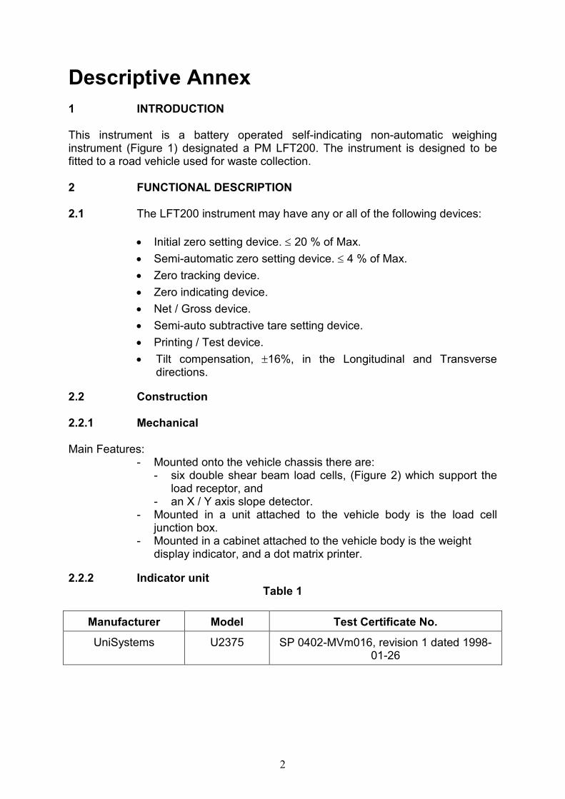
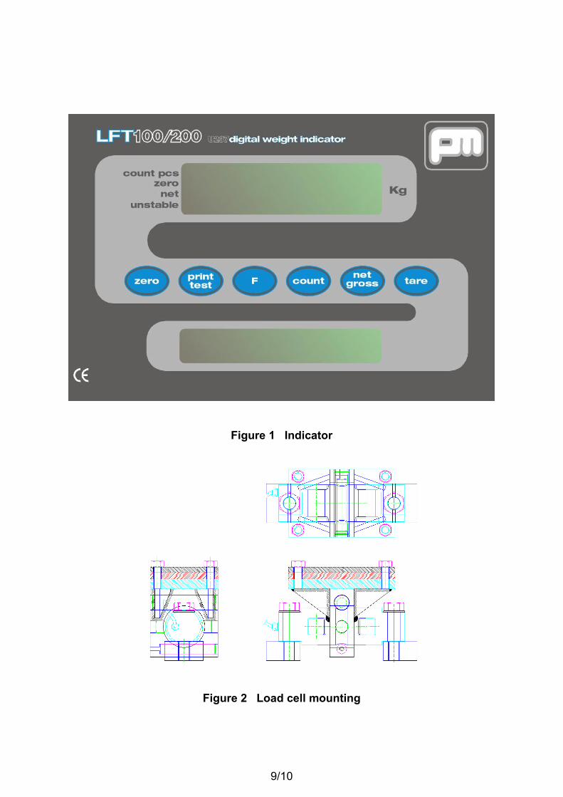
Descriptive Annex 1 INTRODUCTION This instrument is a battery operated self-indicating non-automatic weighing instrument (Figure 1) designated a PM LFT200. The instrument is designed to be fitted to a road vehicle used for waste collection. 2 FUNCTIONAL DESCRIPTION 2.1 The LFT200 instrument may have any or all of the following devices:
• Initial zero setting device. ≤ 20 % of Max.
• Semi-automatic zero setting device. ≤ 4 % of Max.
• Zero tracking device.
• Zero indicating device.
• Net / Gross device.
• Semi-auto subtractive tare setting device.
• Printing / Test device.
• Tilt compensation, ±16%, in the Longitudinal and Transverse directions.
2.2 Construction
2.2.1 Mechanical Main Features:
- Mounted onto the vehicle chassis there are: - six double shear beam load cells, (Figure 2) which support the
load receptor, and - an X / Y axis slope detector.
- Mounted in a unit attached to the vehicle body is the load cell junction box.
- Mounted in a cabinet attached to the vehicle body is the weight display indicator, and a dot matrix printer.
2.2.2 Indicator unit Table 1
Manufacturer Model Test Certificate No.
UniSystems U2375 SP 0402-MVm016, revision 1 dated 1998-01-26
3
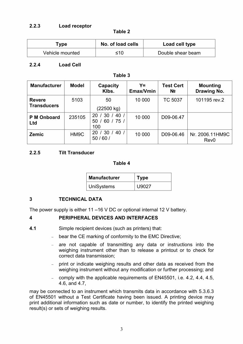
2.2.3 Load receptor Table 2
Type No. of load cells Load cell type
Vehicle mounted ≤10 Double shear beam
2.2.4 Load Cell
Table 3
Manufacturer Model Capacity Klbs.
Y= Emax/Vmin
Test Cert №
Mounting Drawing No.
Revere Transducers
5103 50
(22500 kg)
10 000 TC 5037 101195 rev.2
P M Onboard Ltd
235105 20 / 30 / 40 / 50 / 60 / 75 / 100
10 000 D09-06.47
Zemic HM9C 20 / 30 / 40 / 50 / 60 /
10 000 D09-06.46 Nr. 2006.11HM9C Rev0
2.2.5 Tilt Transducer
Table 4
Manufacturer Type
UniSystems U9027
3 TECHNICAL DATA
The power supply is either 11 –16 V DC or optional internal 12 V battery.
4 PERIPHERAL DEVICES AND INTERFACES
4.1 Simple recipient devices (such as printers) that:
− bear the CE marking of conformity to the EMC Directive;
− are not capable of transmitting any data or instructions into the weighing instrument other than to release a printout or to check for correct data transmission;
− print or indicate weighing results and other data as received from the weighing instrument without any modification or further processing; and
− comply with the applicable requirements of EN45501, i.e. 4.2, 4.4, 4.5, 4.6, and 4.7,
may be connected to an instrument which transmits data in accordance with 5.3.6.3 of EN45501 without a Test Certificate having been issued. A printing device may print additional information such as date or number, to identify the printed weighing result(s) or sets of weighing results.
4
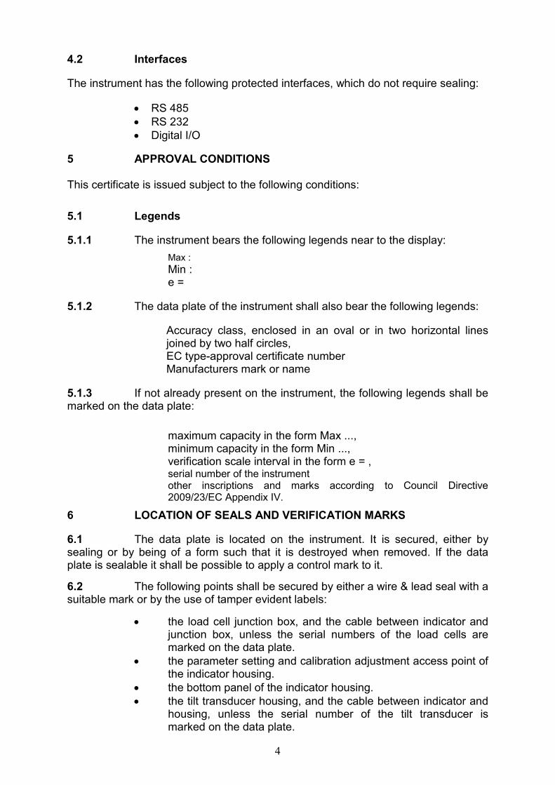
4.2 Interfaces
The instrument has the following protected interfaces, which do not require sealing:
• RS 485
• RS 232
• Digital I/O
5 APPROVAL CONDITIONS This certificate is issued subject to the following conditions:
5.1 Legends
5.1.1 The instrument bears the following legends near to the display:
Max :
Min : e =
5.1.2 The data plate of the instrument shall also bear the following legends:
Accuracy class, enclosed in an oval or in two horizontal lines joined by two half circles, EC type-approval certificate number Manufacturers mark or name
5.1.3 If not already present on the instrument, the following legends shall be marked on the data plate:
maximum capacity in the form Max ..., minimum capacity in the form Min ..., verification scale interval in the form e = , serial number of the instrument other inscriptions and marks according to Council Directive 2009/23/EC Appendix IV.
6 LOCATION OF SEALS AND VERIFICATION MARKS
6.1 The data plate is located on the instrument. It is secured, either by sealing or by being of a form such that it is destroyed when removed. If the data plate is sealable it shall be possible to apply a control mark to it.
6.2 The following points shall be secured by either a wire & lead seal with a suitable mark or by the use of tamper evident labels:
• the load cell junction box, and the cable between indicator and junction box, unless the serial numbers of the load cells are marked on the data plate.
• the parameter setting and calibration adjustment access point of the indicator housing.
• the bottom panel of the indicator housing.
• the tilt transducer housing, and the cable between indicator and housing, unless the serial number of the tilt transducer is marked on the data plate.
5
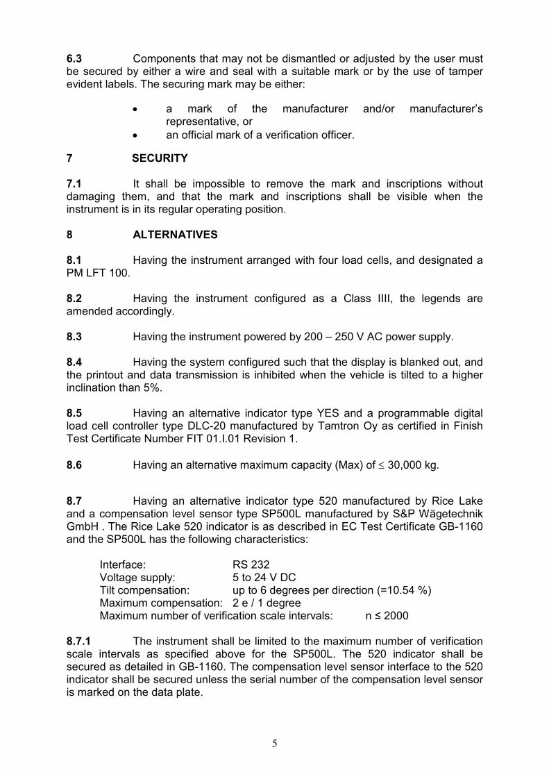
6.3 Components that may not be dismantled or adjusted by the user must be secured by either a wire and seal with a suitable mark or by the use of tamper evident labels. The securing mark may be either:
• a mark of the manufacturer and/or manufacturer’s representative, or
• an official mark of a verification officer.
7 SECURITY 7.1 It shall be impossible to remove the mark and inscriptions without damaging them, and that the mark and inscriptions shall be visible when the instrument is in its regular operating position. 8 ALTERNATIVES 8.1 Having the instrument arranged with four load cells, and designated a PM LFT 100. 8.2 Having the instrument configured as a Class IIII, the legends are amended accordingly. 8.3 Having the instrument powered by 200 – 250 V AC power supply. 8.4 Having the system configured such that the display is blanked out, and the printout and data transmission is inhibited when the vehicle is tilted to a higher inclination than 5%. 8.5 Having an alternative indicator type YES and a programmable digital load cell controller type DLC-20 manufactured by Tamtron Oy as certified in Finish Test Certificate Number FIT 01.I.01 Revision 1.
8.6 Having an alternative maximum capacity (Max) of ≤ 30,000 kg.
8.7 Having an alternative indicator type 520 manufactured by Rice Lake and a compensation level sensor type SP500L manufactured by S&P Wägetechnik GmbH . The Rice Lake 520 indicator is as described in EC Test Certificate GB-1160 and the SP500L has the following characteristics:
Interface: RS 232 Voltage supply: 5 to 24 V DC Tilt compensation: up to 6 degrees per direction (=10.54 %) Maximum compensation: 2 e / 1 degree Maximum number of verification scale intervals: n ≤ 2000
8.7.1 The instrument shall be limited to the maximum number of verification scale intervals as specified above for the SP500L. The 520 indicator shall be secured as detailed in GB-1160. The compensation level sensor interface to the 520 indicator shall be secured unless the serial number of the compensation level sensor is marked on the data plate.
6
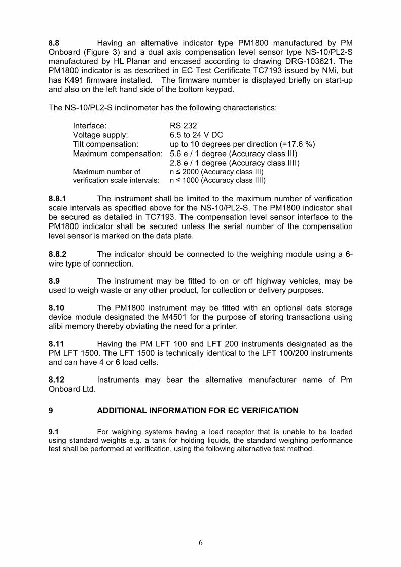
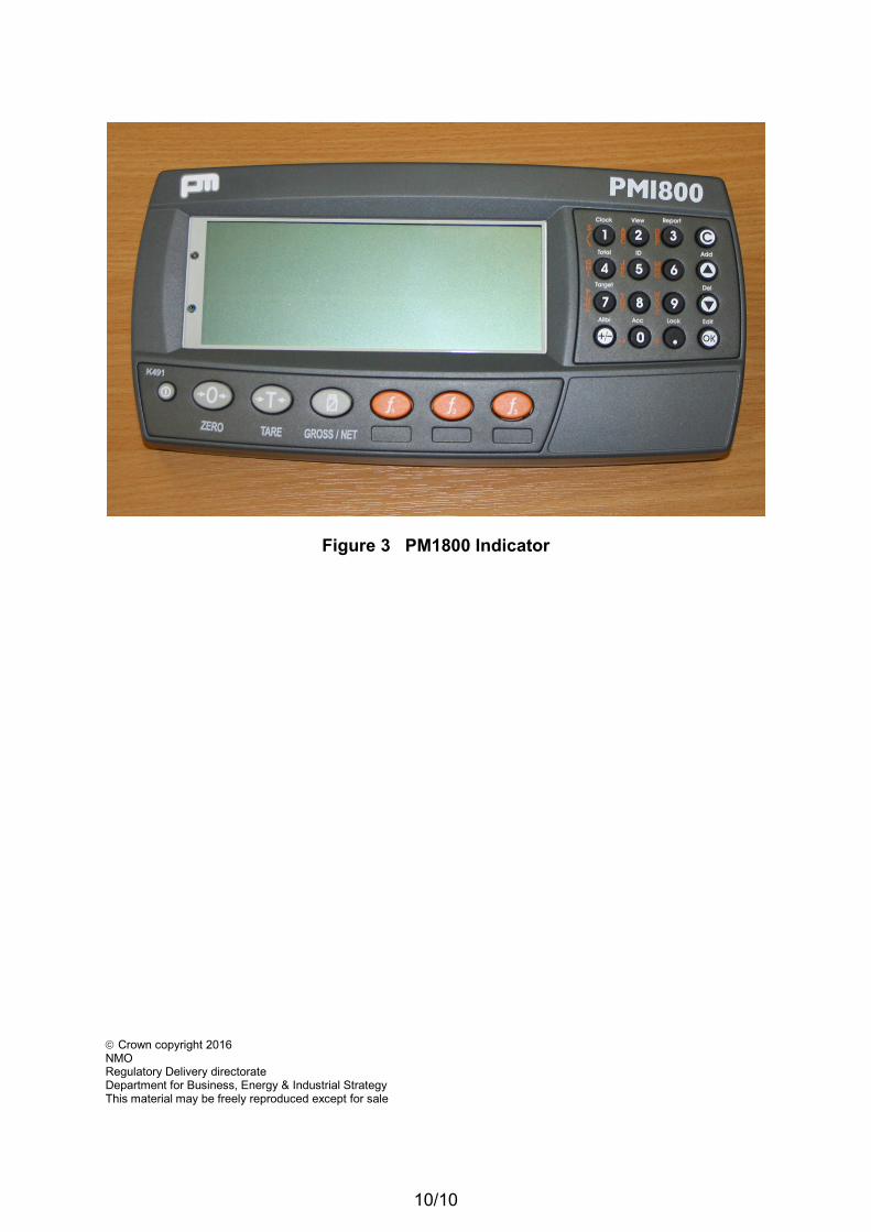
8.8 Having an alternative indicator type PM1800 manufactured by PM Onboard (Figure 3) and a dual axis compensation level sensor type NS-10/PL2-S manufactured by HL Planar and encased according to drawing DRG-103621. The PM1800 indicator is as described in EC Test Certificate TC7193 issued by NMi, but has K491 firmware installed. The firmware number is displayed briefly on start-up and also on the left hand side of the bottom keypad. The NS-10/PL2-S inclinometer has the following characteristics:
Interface: RS 232 Voltage supply: 6.5 to 24 V DC Tilt compensation: up to 10 degrees per direction (=17.6 %) Maximum compensation: 5.6 e / 1 degree (Accuracy class III) 2.8 e / 1 degree (Accuracy class IIII) Maximum number of n ≤ 2000 (Accuracy class III) verification scale intervals: n ≤ 1000 (Accuracy class IIII)
8.8.1 The instrument shall be limited to the maximum number of verification scale intervals as specified above for the NS-10/PL2-S. The PM1800 indicator shall be secured as detailed in TC7193. The compensation level sensor interface to the PM1800 indicator shall be secured unless the serial number of the compensation level sensor is marked on the data plate. 8.8.2 The indicator should be connected to the weighing module using a 6-wire type of connection.
8.9 The instrument may be fitted to on or off highway vehicles, may be used to weigh waste or any other product, for collection or delivery purposes.
8.10 The PM1800 instrument may be fitted with an optional data storage device module designated the M4501 for the purpose of storing transactions using alibi memory thereby obviating the need for a printer.
8.11 Having the PM LFT 100 and LFT 200 instruments designated as the PM LFT 1500. The LFT 1500 is technically identical to the LFT 100/200 instruments and can have 4 or 6 load cells.
8.12 Instruments may bear the alternative manufacturer name of Pm Onboard Ltd.
9 ADDITIONAL INFORMATION FOR EC VERIFICATION
9.1 For weighing systems having a load receptor that is unable to be loaded using standard weights e.g. a tank for holding liquids, the standard weighing performance test shall be performed at verification, using the following alternative test method.
7
9.1.1 For the purposes of this test, a separate control instrument shall be provided which shall enable the checking of the weighing performance to an accuracy greater than either:
(a) one-third of the maximum permissible error if the control instrument is verified immediately prior to the tests, or
(b) one-fifth of the maximum permissible error in all other cases.
9.1.2 Position the weighing system onto the control instrument. The weighing system is then loaded and unloaded with water from a source away from the control instrument. Use the indication of the control instrument to establish the test loads and hence determine the error of the weighing system. Suitable change point weights may be used to meet the accuracy requirements in Section 9.1.1. The quantity of water charged and discharged should be such that the weighing system will be loaded and emptied in a minimum of five steps. Where possible, charge and discharge water such that the loads at or near where the mpe changes are tested, e.g. 500 e.
9.2 Subject to applicable health and safety requirements and practical limitations, tilt testing should be performed on the weighing instrument. The weighing instrument should be tilted longitudinally and transversely by 10% in each case. The method described in Section 9.1 above should be adopted, with the exception that the weighing system is only loaded to 50 % of Max and the number of discharges is reduced as appropriate.
8
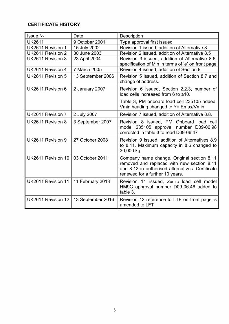
CERTIFICATE HISTORY
Issue № Date Description
UK2611 9 October 2001 Type approval first issued
UK2611 Revision 1 15 July 2002 Revision 1 issued, addition of Alternative 8
UK2611 Revision 2 30 June 2003 Revision 2 issued, addition of Alternative 8.5
UK2611 Revision 3 23 April 2004 Revision 3 issued, addition of Alternative 8.6, specification of Min in terms of ‘e’ on front page
UK2611 Revision 4 7 March 2005 Revision 4 issued, addition of Section 9
UK2611 Revision 5 13 September 2006 Revision 5 issued, addition of Section 8.7 and change of address.
UK2611 Revision 6 2 January 2007 Revision 6 issued, Section 2.2.3, number of load cells increased from 6 to ≤10.
Table 3, PM onboard load cell 235105 added, Vmin heading changed to Y= Emax/Vmin
UK2611 Revision 7 2 July 2007 Revision 7 issued, addition of Alternative 8.8.
UK2611 Revision 8 3 September 2007 Revision 8 issued, PM Onboard load cell model 235105 approval number D09-06.98 corrected in table 3 to read D09-06.47
UK2611 Revision 9 27 October 2008 Revision 9 issued, addition of Alternatives 8.9 to 8.11. Maximum capacity in 8.6 changed to 30,000 kg.
UK2611 Revision 10 03 October 2011 Company name change. Original section 8.11 removed and replaced with new section 8.11 and 8.12 in authorised alternatives. Certificate renewed for a further 10 years.
UK2611 Revision 11 11 February 2013 Revision 11 issued, Zemic load cell model HM9C approval number D09-06.46 added to table 3.
UK2611 Revision 12 13 September 2016 Revision 12 reference to LTF on front page is amended to LFT
9/10
Figure 1 Indicator
Figure 2 Load cell mounting
10/10
Figure 3 PM1800 Indicator
Crown copyright 2016 NMO Regulatory Delivery directorate Department for Business, Energy & Industrial Strategy This material may be freely reproduced except for sale