Embed Size (px)
DESCRIPTION
Service manual for Eu2000i generator
Citation preview

How to use this manualHow to use this manual
A Few Words About SafetySERVICE INFORMATIONThe service and repair information contained in this manual is intended for use by qualified, professional technicians. Attemptingservice or repairs without the proper training, tools, and equipment could cause injury to you and/or others. It could also damagethis Honda product or create an unsafe condition.
This manual describes the proper methods and procedures for performing service, maintenance, and repairs. Some proceduresrequire the use of special tools. Any person who intends to use a replacement part, service procedure, or a tool that is notrecommended by Honda must determine the risks to his or her personal safety and the safe operation of this product.
If you need to replace a part, use Honda Genuine parts with the correct part number or an equivalent part. We strongly recommendthat you do not use replacement parts of inferior quality.
For Your Customer’s SafetyProper service and maintenance are essential to the customer’s safety and the reliability of this product. Any error or oversightwhile servicing this product can result in faulty operation, damage to the product, or injury to others.
For Your SafetyBecause this manual is intended for the professional service technician, we do not provide warnings about many basic shop safetypractices (Hot parts-wear gloves, for example). If you have not received shop safety training or do not feel confident about yourknowledge of safe servicing practice, we recommend that you do not attempt to perform the procedures described in this manual.
Some of the most important general service safety precautions are given below. However, we cannot warn you of everyconceivable hazard that can arise in performing service and repair procedures. Only you can decide whether or not you shouldperform a given task.
Important Safety PrecautionsMake sure you have a clear understanding of all basic shop safety practices and that you are wearing appropriate clothing andusing safety equipment. When performing any service task, be especially careful of the following:
• Read all of the instructions before you begin, and make sure you have the tools, the replacement or repair parts, and the skillsrequired to perform the tasks safely and completely.
• Protect your eyes by using proper safety glasses, goggles, or face shields anytime you hammer, drill, grind, or work aroundpressurized air, pressurized liquids, springs or other stored-energy components. If there is any doubt, put on eye protection.
• Use other protective wear when necessary, for example gloves or safety shoes. Handling hot or sharp parts can cause severeburns or cuts. Before you grab something that looks like it can hurt you, stop and put on gloves.
• Protect yourself and others whenever you have engine-power equipment up in the air. Anytime you lift this product with a hoist,make sure that the hoist hook is securely attached to the product.
Make sure the engine is off before you begin any servicing procedures, unless the instruction tells you to do otherwise. This willhelp eliminate several potential hazards:
• Carbon monoxide poisoning from engine exhaust. Be sure there is adequate ventilation whenever you run the engine. • Burns from hot parts. Let the engine and exhaust system cool before working in those areas. • Injury from moving parts. If the instruction tells you to run the engine, be sure your hands, fingers and clothing are out of the way.
Gasoline vapors and hydrogen gasses from battery are explosive. To reduce the possibility of a fire or explosion, be careful whenworking around gasoline or batteries.
• Use only a nonflammable solvent, not gasoline, to clean parts. • Never store gasoline in an open container. • Keep all cigarettes, sparks, and flames away from the battery and all fuel-related parts.
Improper service or repairs can create an unsafe condition that can cause your customer or others to be seriously hurt or killed.
Follow the procedures and precautions in this manual and other service materials carefully.
Failure to properly follow instructions and precautions can cause you to be seriously hurt or killed.
Follow the procedures and precautions in this manual carefully.
IFC with How to use.fm Page 1 Wednesday, May 9, 2012 2:49 PM
eu2000i_eu2000i companion
EU2000i COMPANION
Revised: September 2008 (PSV61Z0700E5)
INTRODUCTIONThis manual covers service and repair procedures for the Honda EU2000i and EU2000i Companion generators.
All information contained in this manual is based on the latest product information available at the time of printing. We reserve the right to make changes at any time without notice.
No part of this publication may be reproduced, stored in a retrieval system, or transmitted, in any form by any means, electronic, mechanical, photocopying, recording, or otherwise, without prior written permission of the publisher. This includes text, figures, and tables.
As you read this manual, you will find information that is preceded by a symbol. The purpose of this message is to help prevent damage to the generator, other property, or the environment.
SAFETY MESSAGES
Your safety and the safety of others are very important. To help you make informed decisions, we have provided safety messages and other safety information throughout this manual. Of course, it is not practical or possible to warn you about all the hazards associated with servicing these generators. You must use your own good judgement.
You will find important safety information in a variety of forms, including:
• Safety Labels – on the generator.
• Safety Messages – preceded by a safety alert symbol and one of three signal words: DANGER, WARNING, or CAUTION.
These signal words mean:
You WILL be KILLED orSERIOUSLY HURT if you don’tfollow instructions.
You CAN be KILLED orSERIOUSLY HURT if you don’tfollow instructions.
You CAN be HURT if you don’tfollow instructions.
• Instructions – how to service these generators correctly and safely.
American Honda Motor Co., Inc.Service Communications Department
NOTICE
DANGER
WARNING
CAUTION
CONTENTS SPECIFICATIONS 1
SERVICE INFORMATION 2
MAINTENANCE 3
MUFFLER 4
AIR CLEANER/CARBURETOR 5
CONTROL PANEL 6
SIDE COVERS/FUEL TANK/FRONT FRAMES/UNDER COVER 7
RECOIL STARTER/FAN COVER 8
GENERATOR 9
CAM PULLEY/CRANKSHAFT/PISTON/CYLINDER BLOCK 10
OPERATION 11
Revised: October 2012 (PSV61Z0700E9)
eu2000i_eu2000i companion

Revised: September 2008 (61Z0700/PSV61Z0700E5)
EU2000i COMPANION
Date of Issue: February 2004
eu2000i_eu2000i companion

Date of Issue: February 20011-1
EU2000i COMPANION1. SPECIFICATIONS
1. SPECIFICATIONS
1. SPECIFICATIONS............................... 1-1 4. DIMENSIONAL DRAWINGS................1-7
2. CHARACTERISTICS .......................... 1-4 5. WIRING DIAGRAMS............................1-9
3. PERFORMANCE CURVES................. 1-6
EU2000i
Revised: May 2007 (61Z0700/PSV53351-C)
eu2000i_eu2000i companion

Date of Issue: February 20011-2
EU2000i COMPANION
PWM (Pulse width modulation)
eu2000i_eu2000i companion

Revised: October 2012 (PSV61Z0700E9) 1-3
EU2000i COMPANION
EU2000i Companion
Model EU2000i COMPANION
Type AC1 *1, AN1 *2
Overall length 512 mm (20.2 in)
Overall width 290 mm (11.4 in)
Overall height 425 mm (16.7 in)
Dry weight 20.8 kg (45.9 Ib)
Operating weight 23.9 kg (52.7 Ib)
DIMENSIONS AND WEIGHTS
ENGINE
Model GX100
Description code GCANM
Type 4-stroke, overhead camshaft single cylinder
Displacement 98.5 cm3 (6.01 cu-in)
Bore x stroke 56.0 x 40.0 mm (2.20x 1.57 in)
Compression ratio 8.5 ± 0.2 : 1
Cooling system Forced air
Ignition system Full transistor
Ignition timing 25° ± 2° B.T.D.C.
Spark plug CR5HSB (NGK)
Carburetor Float type, Horizontal butterfly valve type
Air cleaner Semi-dry type
Governor Electronic control type
Lubrication system Forced splash
Oil capacity 0.40 (0.42 US qt, 0.35 lmp qt)
Recommended oil SAE 10W-30
Starting system Recoil starter
Stopping system Ignition primary circuit ground
Fuel used Regular unleaded gasoline (86 pump octane)
*1: California type*2: Non-California type
GENERATOR
Model EU2000i COMPANION
Description code EAAJ
Generator type Multi-pole field rotation typeGenerator structure Self-ventilation drip-proof type
Excitation Self-excitation (Magnet type)
Voltage regulation system PWM (Pulse Width Modulation)Phase Single phase
Rotating direction Clockwise (Viewed from the generator)
Frequency regulation DC-AC conversion (Inverter type)
Revised: October 2012 (PSV61Z0700E9)
eu2000i_eu2000i companion
Date of Issue: February 20011-4
EU2000i COMPANION
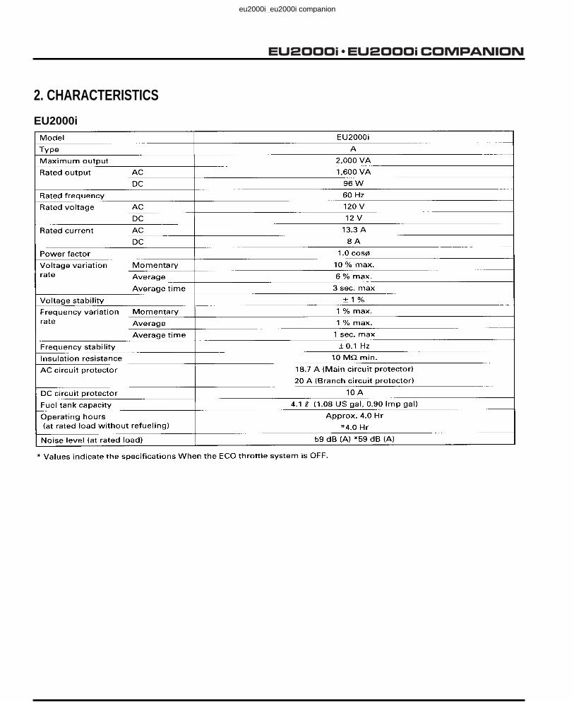
2. CHARACTERISTICS
EU2000i
eu2000i_eu2000i companion

Revised: October 2012 (PSV61Z0700E9)1-5
EU2000i COMPANION
Model EU2000i COMPANION
Type AC1, AN1
Maximum output 2.0 kVA
AC rated output 1.6 kVA
Rated frequency 60 Hz
AC rated voltage 120 V
AC rated current 13.3 A
Power factor 1.0 cos Momentary
Average
Average time
10 % max.
6% max.
3 sec. max.
Voltage stability ± 1 % max.
Momentary
Average
Average time
1 % max.
1 % max.
1 sec. max.
Frequency stability ± 0.1 Hz max.
Insulation resistance 10 M min.AC circuit protector 18.7 A
Fuel tank capacity 3.6 (0.95 US gal, 0.79 lmp gal)
Fuel consumption(at rated load) 1.07 (0.28 US gal, 0.24 Imp gal)/Hr
Operating hours(at rated load without refueling)
Approx. 3.4 Hr
Noise level (LwA) (Rated) LwA 89 dB (A)
2. CHARACTERISTICS
Voltagevariationrate
Frequencyvariationrate
Revised: October 2012 (PSV61Z0700E9)
EU2000i Companion
eu2000i_eu2000i companion

Date of Issue: February 20011-6
EU2000i COMPANION
EU2000i, EU2000i Companion
EU2000i only
Revised: October 2012 (PSV61Z0700E9)
eu2000i_eu2000i companion

Date of Issue: February 20011-7
EU2000i COMPANION
EU2000i
eu2000i_eu2000i companion

Revised: October 2012 (PSV61Z0700E9)1-8
EU2000i COMPANION
512 mm (20.2 in)
425 m
m (
16.7
in
)
290 m
m (
11.4
in
)
Unit: mm (in)EU2000i Companion
eu2000i_eu2000i companion
Date of Issue: February 2001
1-9
E
U2
00
0i C
OM
PA
NIO
N
5. WIR
ING
DIA
GR
AM
S
EU
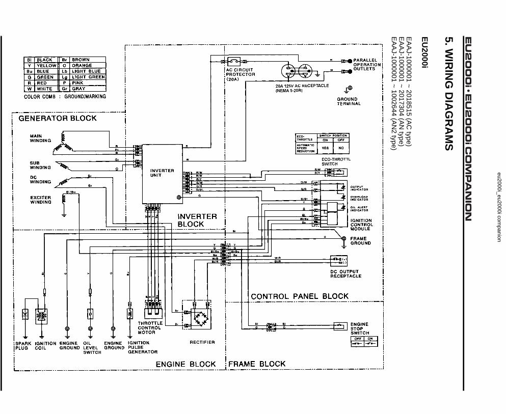
2000i
EA
AJ-1000001 ~ 2018515 (A
C type)
EA
AJ-1000001 ~ 2017304 (A
N type)
EA
AJ-1000001 ~ 1002644 (A
N2 type)
Revised: O
ctober 2012 (PS
V61Z0700E
9)
eu2000i_eu2000i companion

Date of Issue: February 2001
1-10
E
U2
00
0i C
OM
PA
NIO
N
EA
AJ-2018516 ~ forw
ard (AC
type)E
AA
J-2017305 ~ forward (A
N type)
EA
AJ-1002645 ~ forw
ard (AN
2 type)
R
W
R/W
RW
R/WR/Y
G/RG/Bl
G
RWBu
Gr
P
Br
Br
Bl/Bu
Bl
G GY Bu
W R Y Bu
W R Y Bu
Br
BlG
BlG
Y
BuW/RBl/R
Bl/Bu
Y
Bu
Bl
GGBl/Bu
Br
W/R
G
Bl/R
R/WR/Y
G/R
G/BlY
G
Bl
BuBl/Bu
( )( )
Bl
Bu
Y
G
R
W
Br
Lb
O
Lg
P
Gr
BLACK
COLOR COMB : GROUND/MARKING
YELLOW
BLUE
GREEN
RED
WHITE
BROWN
ORANGE
LIGHT BLUE
LIGHT GREEN
PINK
GRAY
ECO-THROTTLE
AUTOMATICSPEEDREDUCTION
SWITCH POSITION
ON OFF
YES NO
GROUNDTERMINAL
ECO-THROTTLESWITCH
IGNITION CONTROLMODULE
FRAME GROUND
DC OUTPUTRECEPTACLE
ENGINESTOP SWITCH
OUTPUT INDICATOR
OVERLOAD INDICATOR
OIL ALERT INDICATOR
RECTIFIER
IGNITIONPULSEGENERATOR
ENGINEGROUND
ENGINEGROUND
IGNITIONCOIL
SPARKPLUG
OILLEVELSWITCH
THROTTLECONTROLMOTOR
EXCITERWINDING
DCWINDING
SUBWINDING
MAINWINDING
INVERTERUNIT
CONTROL PANEL BLOCK
FRAME BLOCKENGINE BLOCK
INVERTERBLOCK
GENERA TORBLOCK
AC CIRCUITPROTECTOR(20A)
20A 125V AC RECEPTACLE(NEMA 5-20R)
PARALLELOPERATION OUTLETS
ENGINE STOP SWITCH
SWITCH POSITION
ON OFF
Revised: O
ctober 2012 (PS
V61Z0700E
9)
eu2000i_eu2000i companion

Revised: O
ctober 2012 (PS
V61Z0700E
9)1-11
E
U2
00
0i C
OM
PA
NIO
N
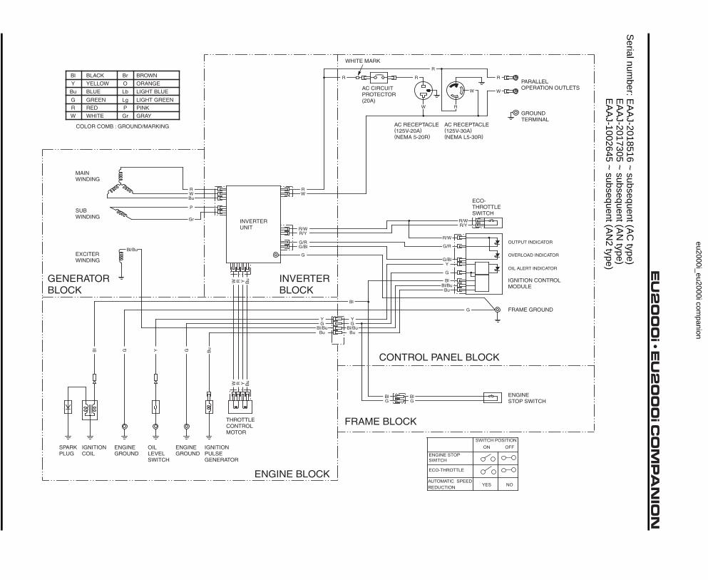
EU
2000i Co
mp
anio
n
Serial num
ber: EA
AJ-1000001 ~ 2018515 (A
C type)
EA
AJ-1000001 ~ 2017304 (A
N type)
EA
AJ-1000001 ~ 1002644 (A
N2 type)
ENGINE STOP SWITCH
SWITCH POSITION
ON OFF
AC PLUGS
1 20A 125V DUPLEX (NEMA 5-20P)
2 30A 125V LOCKING PLUG (NEMA L5-30P)
ONOFF
NO CONTINUITYCONTINUITY
ECO THROTTLE SWONOFF NO CONTINUITY
CONTINUITYENGINE STOP SWITCHNO OIL
PROPER OIL NO CONTINUITYCONTINUITY
OIL LEVEL SWITCH
eu2000i_eu2000i companion
Revised: O
ctober 2012 (PS
V61Z0700E
9)1-12
E
U2
00
0i C
OM
PA
NIO
N
Serial num
ber: EA
AJ-2018516 ~ subsequent (A
C type)
EA
AJ-2017305 ~ subsequent (A
N type)
EA
AJ-1002645 ~ subsequent (A
N2 type)
R
R
R
RR
W
W
W
R/W
RW
R/WR/Y
G/RG/Bl
G
RWBu
Gr
P
Bl/Bu
Bl
G GY Bu
W R Y Bu
W R Y Bu
BlG
BlG
Y
BuBl/Bu
Y
Bu
Bl
GGBl/Bu
G
R/WR/Y
G/R
G/BlY
G
Bl
BuBl/Bu
Bl
Bu
Y
G
R
W
Br
Lb
O
Lg
P
Gr
BLACK
COLOR COMB : GROUND/MARKING
YELLOW
BLUE
GREEN
RED
WHITE
BROWN
ORANGE
LIGHT BLUE
LIGHT GREEN
PINK
GRAY
AC CIRCUITPROTECTOR(20A)
WHITE MARK
AC RECEPTACLE(125V-20A)(NEMA 5-20R)
AC RECEPTACLE(125V-30A)(NEMA L5-30R)
GROUNDTERMINAL
PARALLELOPERATION OUTLETS
ECO-THROTTLESWITCH
IGNITION CONTROLMODULE
FRAME GROUND
ENGINESTOP SWITCH
OUTPUT INDICATOR
OVERLOAD INDICATOR
OIL ALERT INDICATOR
IGNITIONPULSEGENERATOR
ENGINEGROUND
ENGINEGROUND
IGNITIONCOIL
SPARKPLUG
OILLEVELSWITCH
THROTTLECONTROLMOTOR
EXCITERWINDING
SUBWINDING
MAINWINDING
INVERTERUNIT
FRAME BLOCK
ENGINE BLOCK
INVERTERBLOCK
GENERATORBLOCK
CONTROL PANEL BLOCK
ENGINE STOP SWITCH
ECO-THROTTLE
AUTOMATIC SPEEDREDUCTION
SWITCH POSITIONON OFF
YES NO
eu2000i_eu2000i companion

Date of Issue: February 20012-1
EU2000i COMPANION 2. SERVICE INFORMATION
1. SYMBOLS USED IN THIS MANUAL.. 2-1 5. TORQUE VALUES...............................2-5
2. SERIAL NUMBER LOCATIONS......... 2-1 6. SPECIAL TOOLS.................................2-6
3. ELECTRIC PRECAUTIONS................ 2-2 7. TROUBLESHOOTING.........................2-7
4. MAINTENANCE STANDARDS........... 2-3 8. CABLE & HARNESS ROUTING .........2-28
eu2000i_eu2000i companion

Date of Issue: February 20012-2
EU2000i COMPANION
eu2000i_eu2000i companion

Date of Issue: February 20012-3
EU2000i COMPANION
eu2000i_eu2000i companion
Date of Issue: February 20012-4
EU2000i COMPANION
eu2000i_eu2000i companion

Date of Issue: February 20012-5
EU2000i COMPANION
eu2000i_eu2000i companion

Date of Issue: February 20012-6
EU2000i COMPANION
eu2000i_eu2000i companion
Date of Issue: February 20012-7
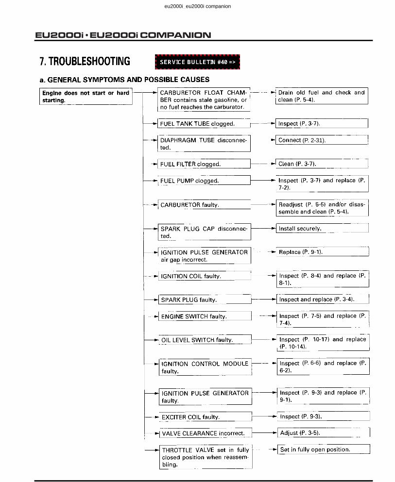
EU2000i COMPANION
(P. 2-31).
(P. 6-6)
Revised: October 2012 (PSV61Z0700E9)
eu2000i_eu2000i companion

Date of Issue: February 20012-8
EU2000i COMPANION
(P. 2-21).
(P. 2-21).
(P. 6-6).
Revised: October 2012 (PSV61Z0700E9)
eu2000i_eu2000i companion

Date of Issue: February 20012-9
EU2000i COMPANION
eu2000i_eu2000i companion

Date of Issue: February 20012-10
EU2000i COMPANION
(P. 2-19).
Revised: May 2012 (PSV61Z0700E8)
eu2000i_eu2000i companion

Date of Issue: February 20012-11
EU2000i COMPANION
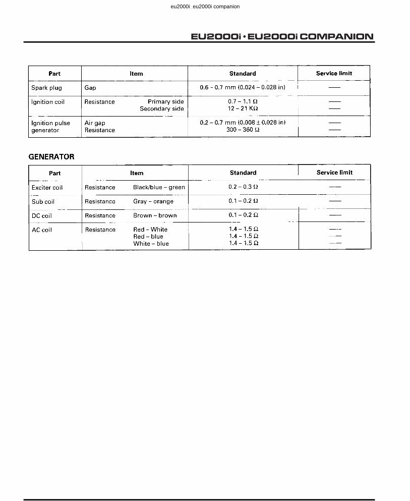
Adjust the spark plug gap or replace the spark plug as necessary (P. 3-4).
(P. 2-19).
Revised: May 2012 (PSV61Z0700E8)
eu2000i_eu2000i companion

Date of Issue: February 20012-12
EU2000i COMPANION
c. IGNITION SYSTEM
Make a copy of the EU2000i Ignition System Troubleshooting Worksheet (page 2-17) and document your test results for future reference or in case you need to call Techline.When troubleshooting the ignition system, complete all of the component test procedures before replacing any component. Review your test results in the Conclusion section (page 2-17) to determine the cause of the problem.
1. Turn the engine stop switch to the ON position and pull the starter grip. Verify the Oil Alert® indicator is not flashing.
If flashing, add oil to bring the level to the upper limit and recheck the Oil Alert indicator is not flashing.
2. Remove the maintenance cover.
3. Clamp the carburetor inlet fuel line as shown.
4. Drain the carburetor float bowl.
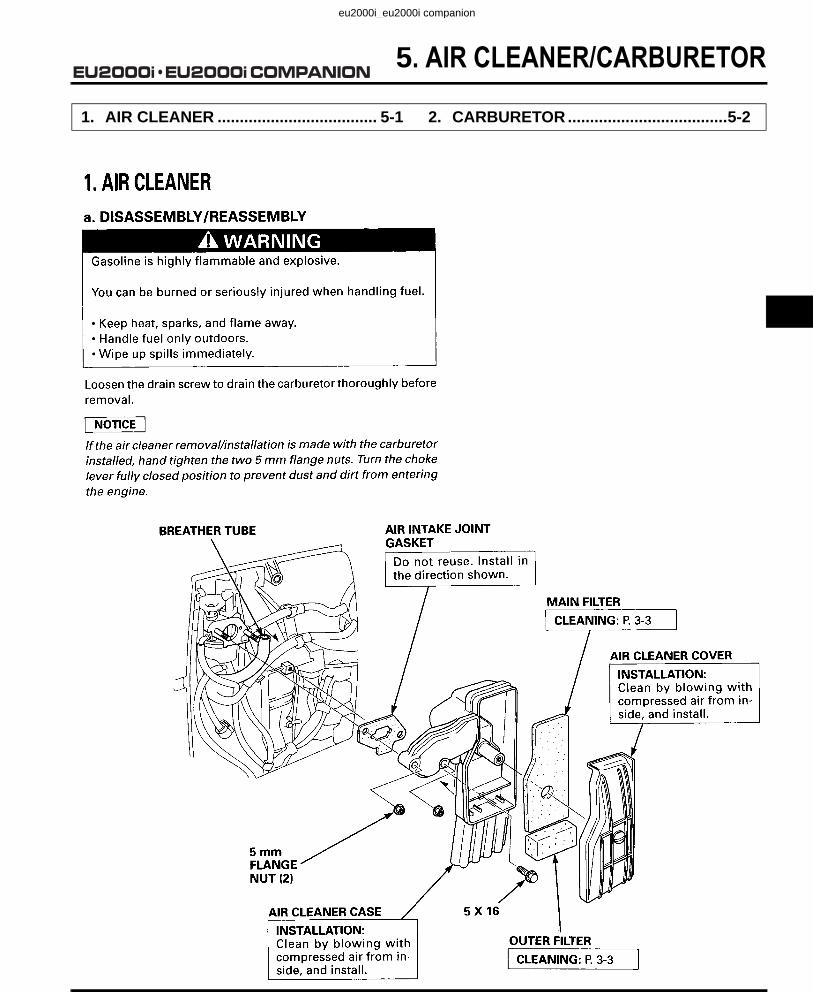
WARNING
Gasoline is highly flammable and explosive.If ignited, gasoline can burn you severely.Be sure there is no spilled fuel near the engine before performing this test.
OIL ALERT® INDICATOR
HOSE PINCHING PLIERS, SUN-HCP6(Commercially available)
Revised: May 2012 (PSV61Z0700E8)
eu2000i_eu2000i companion

Date of Issue: February 20012-13
EU2000i COMPANION
5. With the engine stop switch in the OFF position, remove the spark plug and pull the starter grip several times to remove any unburned fuel from the combustion chamber.
6. Insert the spark plug into the spark plug boot.
7. Set the engine stop switch to the ON position.
8. Ground the negative (-) electrode (threaded part) of the spark plug against the shroud.
9. Pull the starter grip and check for spark at the spark plug.
If there is no spark at the spark plug, replace the spark plug with a new one and recheck for spark.
Continue on if still no spark.
10. Remove the control panel 5 x 16 mm self-tapping screws to access the ICM 8-pin wire harness connector. Disconnect the ICM 8-pin connector.
Use the Terminal Inspection Feeler Set, 07XMJ-001000A, to check continuity of the ICM connector and related wire harness test points. Clean the blue band gauge terminal, insert it in the appropriate connector terminal, and then attach the meter test lead onto the gauge.
Insert the appropriate size feeler into the connector terminal. Using the wrong size may damage the connector terminal, causing a loss of continuity when the ICM harness connector is reconnected to the ICM.
11. Check continuity of the engine stop switch. Check between the black wire and green wire at the ICM 8-pin wire harness.
• There should be continuity with the engine stop switch in the OFF position.
• There should be no continuity with the engine stop switch in the ON position.
Document your results and continue.
5 x 16 mm SELF-TAPPING SCREWS (4)
CONTROL PANEL
ICM 8-PIN WIRE HARNESS CONNECTOR
ICM
ENGINE STOP SWITCH 2-PIN CONNECTOR
07XM
J-0010004A
TERMINAL INSPECTION FEELER SET, 07XMJ-001000A
METER TEST LEAD
ICM WIRE HARNESS CONNECTOR
BLUE BAND FEELER
R/W G/Bl G/R B/Bu G Bu Y Bl
ICM 8-PIN WIRE HARNESS CONNECTOR
Revised: May 2012 (PSV61Z0700E8)
eu2000i_eu2000i companion

Date of Issue: February 20012-14
EU2000i COMPANION
12. Test the oil level switch. Make sure the oil level in the engine is correct and the generator is on a level surface. Check for continuity between the yellow wire and ground at the ICM 8-pin wire harness connector.
• There should be no continuity with the proper oil level.
• There should be continuity with the oil drained.
Document your results and continue.
13. Measure the resistance of the ignition pulse generator (IPG). Check between the blue wire at the ICM 8-pin wire harness connector and ground.
Specification: 300 ~ 360
Document your results and continue.
14. Measure the DC millivolt output of the ignition pulse generator (IPG). Check between the blue wire at the ICM 8-pin wire harness connector and ground while pulling the starter grip.
Specification: 3 ~ 4 mVDC
Document your results and continue.
15. Measure the resistance of the exciter winding. Check between the black/blue wire at the ICM 8-pin wire harness connector and ground.
Specification: 0.2 ~ 0.3
Document your results and continue.
If the exciter winding measures a little over the specification, it may not need to be replaced. Additional resistance of 0.4 ~ 0.5 ohms will not cause a no-spark condition.
16. Measure the AC voltage output of the exciter winding. Check between the black/blue wire at the ICM 8-pin wire harness connector and ground while pulling the starter grip.
Specification: 4 ~ 5 VAC
Document your results and continue.
17. Measure the ignition coil resistance.
Primary winding: With the engine stop switch in the ON position, check the resistance between black wire at the ICM 8-pin wire harness connector and ground.
Document your results and continue.
Specification: 0.7 ~ 1.1
If the ignition coil measures a little over the specification, it may not need to be replaced. Additional resistance of 0.4 ~ 0.5 ohms will not cause a no-spark condition.
Secondary winding: With the engine stop switch in the ON position, check resistance between the black wire at the ICM 8-pin wire harness connector and the spark plug cap.
Specification: 12 ~ 21 K
Document your results and continue.
R/W G/Bl G/R B/Bu G Bu Y Bl
ICM 8-PIN WIRE HARNESS CONNECTOR
R/W G/Bl G/R B/Bu G Bu Y Bl
ICM 8-PIN WIRE HARNESS CONNECTOR
R/W G/Bl G/R B/Bu G Bu Y Bl mVICM 8-PIN WIRE HARNESS CONNECTOR
R/W G/Bl G/R G Bu Y BlB/Bu
ICM 8-PIN WIRE HARNESS CONNECTOR
R/W G/Bl G/R G Bu Y BlB/Bu V~ICM 8-PIN WIRE HARNESS CONNECTOR
R/W G/Bl G/R B/Bu G Bu Y Bl
ICM 8-PIN WIRE HARNESS CONNECTOR
R/W G/Bl G/R B/W G Bu Y Bl
SPARK PLUG CAP
ICM 8-PIN WIRE HARNESS CONNECTOR
Revised: May 2012 (PSV61Z0700E8)
eu2000i_eu2000i companion

Date of Issue: February 20012-15
EU2000i COMPANION
Perform the following tests only if the readings in step 17 were out of specification.18. Remove the maintenance cover
19. Disconnect the engine stop switch 2-pin connector.
20. Check the wire harness for breaks.
a. Check for continuity between the black wire at the ICM 8-pin wire harness connector and the engine stop switch 2-pin connector.
b. Check for continuity between the black wire at the ICM 8-pin wire harness connector and the ignition coil female bullet connector.
c. Check for continuity between the green wire at the ICM 8-pin wire harness connector and the green wire at the engine stop switch 2-pin connector.
R/W G/Bl G/R B/Bu G Bu Y Bl
Bl G
ICM 8-PIN WIRE HARNESS CONNECTOR
ENGINE STOP SWITCH 2-PIN CONNECTOR
R/W G/Bl G/R G Bu Y BlB/Bu
ICM 8-PIN WIRE HARNESS CONNECTOR
IGNITION COIL FEMALE BULLET CONNECTOR
R/W G/Bl G/R B/Bu G Bu Y Bl
Bl G
ICM 8-PIN WIRE HARNESS CONNECTOR
ENGINE STOP SWITCH 2-PIN CONNECTOR
Revised: May 2012 (PSV61Z0700E8)
Revised: December 2008 (PSV61Z0700E5-A)
eu2000i_eu2000i companion

Date of Issue: February 20012-16
EU2000i COMPANION
d. Check for continuity between the green wire at the ICM 8-pin wire harness connector and the engine ground terminal.Document your results and continue.
21. Inspect the ignition control module (ICM) pins and ICM wire harness connector for loose, dirty, or corroded connections.
Green colored deposits on the pins or terminals are an indication of corrosion.
• If corrosion is present on the ICM pins or the ICM wire harness, replace the ICM and wire harness and recheck for spark.
• If the ICM and ICM wire harness are OK, go to the conclusion.
Document your results and continue.
22. Reassemble the generator after repairs have been made.
TOOL ORDERING INFORMATIONThe following special tool is used in this job aid:
This tool is distinguished by the special tool box icon. It is available through the American Honda Parts Department and ordered by using normal American Honda Parts ordering procedures.
Tool Number Description
07XMJ-001000A Terminal Inspection Feeler Set
R/W G/Bl G/R B/W G Bu Y BlICM 8-PIN WIRE HARNESS CONNECTOR
ENGINE GROUND TERMINAL
5 X 16 mm SELF-TAPPING SCREW (4)
INSPECT FOR CORROSION
CONTROL PANEL
ICM WIRE HARNESS CONNECTOR
IGNITION CONTROL MODULE (ICM)
Revised: October 2012 (PSV61Z0700E9)
eu2000i_eu2000i companion
Date of Issue: February 20012-17
EU2000i COMPANION
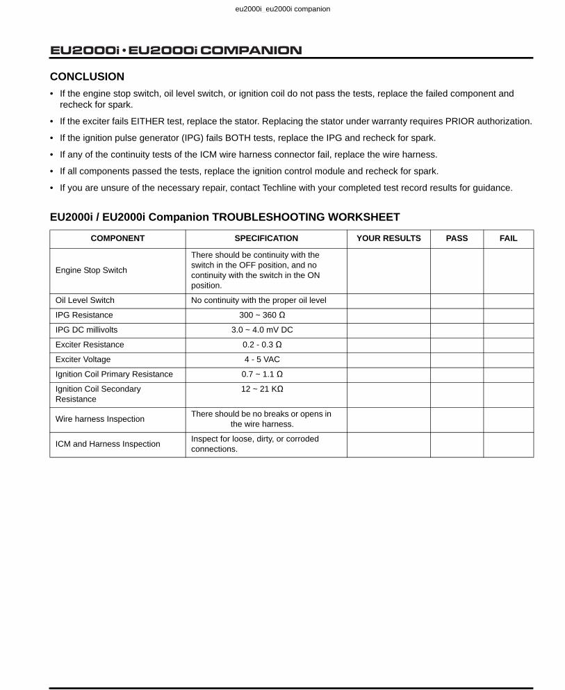
CONCLUSION
• If the engine stop switch, oil level switch, or ignition coil do not pass the tests, replace the failed component and recheck for spark.
• If the exciter fails EITHER test, replace the stator. Replacing the stator under warranty requires PRIOR authorization.
• If the ignition pulse generator (IPG) fails BOTH tests, replace the IPG and recheck for spark.
• If any of the continuity tests of the ICM wire harness connector fail, replace the wire harness.
• If all components passed the tests, replace the ignition control module and recheck for spark.
• If you are unsure of the necessary repair, contact Techline with your completed test record results for guidance.
EU2000i / EU2000i Companion TROUBLESHOOTING WORKSHEET
COMPONENT SPECIFICATION YOUR RESULTS PASS FAIL
Engine Stop Switch
There should be continuity with the switch in the OFF position, and no continuity with the switch in the ON position.
Oil Level Switch No continuity with the proper oil level
IPG Resistance 300 ~ 360 Ω
IPG DC millivolts 3.0 ~ 4.0 mV DC
Exciter Resistance 0.2 - 0.3 Ω
Exciter Voltage 4 - 5 VAC
Ignition Coil Primary Resistance 0.7 ~ 1.1 Ω
Ignition Coil Secondary Resistance
12 ~ 21 KΩ
Wire harness Inspection There should be no breaks or opens in the wire harness.
ICM and Harness Inspection Inspect for loose, dirty, or corroded connections.
Revised: October 2012 (PSV61Z0700E9)
eu2000i_eu2000i companion

Date of Issue: February 20012-18
EU2000i COMPANION
eu2000i_eu2000i companion

Date of Issue: February 20012-19
EU2000i COMPANION
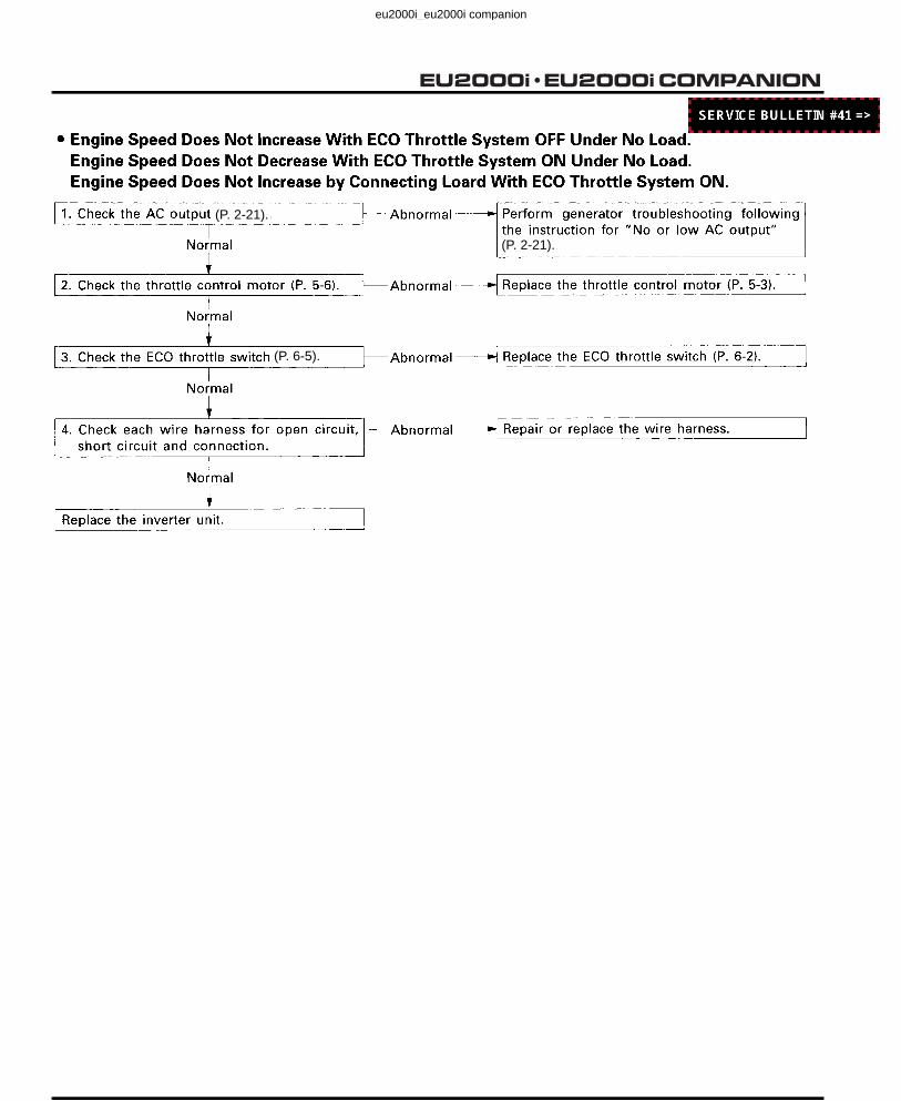
d. THROTTLE CONTROL SYSTEM
(P. 2-21).
(P. 2-21).
(P. 2-21).
(P. 2-21).
(P. 2-11).
Revised: May 2012 (PSV61Z0700E8)
eu2000i_eu2000i companion
Date of Issue: February 20012-20
EU2000i COMPANION
(P. 2-21).
(P. 2-21).
(P. 6-5).
Revised: October 2012 (PSV61Z0700E9)
eu2000i_eu2000i companion

Date of Issue: February 20012-21
EU2000i COMPANION
e. GENERATOR
• EU2000i / EU2000i Companion (EAAJ-1000001 ~ 2017304)
Use a load bank (available through the Honda Tool and Equipment Program or the Parts Division) to verify the customer’s initial complaint and the generator’s performance after the repairs (see page 5-2 of the Generator Troubleshooting Manual).COMPLAINT: Abnormal output (none, low, or high) at the receptacle. Normal: 120 VAC ± 10.With the engine running, check that the overload indicator light is OFF and the AC circuit protectors are ON.
WARNING
High voltage and electrical current present. Touching the non-insulated portions of the meter leads or generator wiring can cause shock or electrocution.Wear insulated gloves and avoid handling non-insulated wiring.
1. Start the engine. Is the green indicator light ON?
ON
• Check the receptacles.
• Check the circuit protectors.
• Check the wiring from the inverter to the control panel.
2. With the engine running, is the red indicator light steady or off.
3.
OUTPUT INDICATOR LIGHT
OFF
OVERLOAD INDICATOR LIGHT
STEADY OFF
The generator output capacity has been exceeded. Turn the engine switch OFF to reset the electronic breaker, and then restart the engine. If still on steady, proceed to step 4.
Proceed to step 4.
Revised: October 2012 (PSV61Z0700E9)
eu2000i_eu2000i companion

Date of Issue: February 20012-22
EU2000i COMPANION
4. a. Stop the engine.
b. Open the maintenance cover.
c. Disconnect the 6-pin connector from the inverter. With the 6-pin connector disconnected, the Eco-Throttle will not operate.
d. Manually set the rpm by moving the throttle lever with your finger.Standard no-load speed 4,200 ~ 4,600 rpm.
5. Operating the engine at 4,200 ~ 4,600 rpm, check the specified voltages at the locations shown.
Generator Test Points
Proceed to step 8.Check for short or open in the stator windings.
Rotor magnet(s) weak. Call Techline before replacing the rotor.Reassemble the generator.Proceed to step 9.
6. Stop the engine.Measure the resistance between the terminals at the locations shown.
Generator Test Points
7. Call Techline before replacing the stator. Reassemble the generator. Call Techline.
Proceed to step 9.
MAINTENANCE COVER
6-PIN CONNECTOR
THROTTLE LEVER
ConnectorColor/test points
Winding Specified Voltage
White and Red
Blue and Red Main Winding 207 ~ 243 VAC
Orange and Gray Sub Winding 8 ~ 16 VAC
WHITE
BLUE
RED
ORANGE
GRAY
OK NG All windings test equally LOW
ConnectorColor/test points
Winding Specified Resistance
White and Red
Blue and Red Main Winding 1.4 ~ 1.5 Ω
Orange and Gray Sub Winding 0.1 ~ 0.2 Ω
WHITE
BLUE
RED
ORANGE
GRAY
NG OK
Revised: October 2012 (PSV61Z0700E9)
eu2000i_eu2000i companion

Date of Issue: February 20012-23
EU2000i COMPANION
GENERATOR TEST POINTS
8. Replace the inverter. Call Techline before replacing the inverter. Reassemble the generator.Proceed to step 9.
9. Test the generator using a load bank. The generator must carry the rated output.Maximum output:120V, 2.0 kVA, 16.6 AmpsRated output:120V, 1.8 kVA, 13.3 Amps
Engine performance problem. Check the following:• Carbon deposits in combustion
chamber or spark arrester• Fuel system• Engine compression• Ignition system
Repair as necessary andrepeat step 9.
OK
Problem is in the load or customer usage. Verify generator usage.
NG
BLUE RED
WHITE
ORANGE GRAY
6-PIN CONNECTOR
Test at the 6-pin connector with it unplugged from the inverter.
Revised: October 2012 (PSV61Z0700E9)
eu2000i_eu2000i companion

Date of Issue: February 20012-24
EU2000i COMPANION
• EU2000iK1 / EU2000iK1 Companion (EAAJ-2017305 ~ SUBSEQUENT)
Use a load bank (available through the Honda Tool and Equipment Program or the Parts Division) to verify the customer’s initial complaint and the generator’s performance after the repairs (see page 5-2 of the Generator Troubleshooting Manual).COMPLAINT: Abnormal output (none, low, or high) at the receptacle. Normal: 120 VAC ± 10.With the engine running, check that the overload indicator light is OFF and the AC circuit protectors are ON.
WARNING
High voltage and electrical current present. Touching the non-insulated portions of the meter leads or generator wiring can cause shock or electrocution.Wear insulated gloves and avoid handling non-insulated wiring.
1. Start the engine. Is the green indicator light ON?
ON
• Check the receptacles.
• Check the circuit protectors.
• Check the wiring from the inverter to the control panel.
2. With the engine running, is the red indicator light steady or off.
3.
OUTPUT INDICATOR LIGHT
OFF
OVERLOAD INDICATOR LIGHT
STEADY OFF
The generator output capacity has been exceeded. Turn the engine switch OFF to reset the electronic breaker, and then restart the engine. If still on steady, proceed to step 4.
Proceed to step 4.
Revised: October 2012 (PSV61Z0700E9)
eu2000i_eu2000i companion

Date of Issue: February 20012-25
EU2000i COMPANION
4. a. Stop the engine.
b. Open the maintenance cover.
c. Disconnect the 6-pin connector from the inverter. With the 6-pin connector disconnected, the Eco-Throttle will not operate.
d. Manually set the rpm by moving the throttle lever with your finger.Standard no-load speed 4,200 ~ 4,600 rpm.
5. Operating the engine at 4,200 ~ 4,600 rpm, check the specified voltages at the locations shown.
Generator Test Points
Proceed to step 8.Check for short or open in the stator windings.
Rotor magnet(s) weak. Call Techline before replacing the rotor.Reassemble the generator.Proceed to step 9.
6. Stop the engine.Measure the resistance between the terminals at the locations shown.
Generator Test Points
7. Call Techline before replacing the stator. Reassemble the generator. Call Techline.
Proceed to step 9.
MAINTENANCE COVER
6-PIN CONNECTOR
THROTTLE LEVER
ConnectorColor/test points
Winding Specified Voltage
Red and White
Blue and Red Main Winding 207 ~ 243 VAC
Pink and Gray Sub Winding 8 ~ 16 VAC
WHITE
BLUE
RED
PINK
GRAY
OK NG All windings test equally LOW
ConnectorColor/test points
Winding Specified Resistance
Red and White
Blue and Red Main Winding 1.4 ~ 1.5 Ω
Pink and Gray Sub Winding 0.1 ~ 0.2 Ω
WHITE
BLUE
RED
PINK
GRAY
NG OK
Revised: October 2012 (PSV61Z0700E9)
eu2000i_eu2000i companion

Date of Issue: February 20012-26
EU2000i COMPANION
GENERATOR TEST POINTS
8. Replace the inverter. Call Techline before replacing the inverter. Reassemble the generator.Proceed to step 9.
9. Test the generator using a load bank. The generator must carry the rated output.Maximum output:120V, 2.0 kVA, 16.6 AmpsRated output:120V, 1.8 kVA, 13.3 Amps
Engine performance problem. Check the following:• Carbon deposits in combustion
chamber or spark arrester• Fuel system• Engine compression• Ignition system
Repair as necessary andrepeat step 9.
OK
Problem is in the load or customer usage. Verify generator usage.
NG
6-PIN CONNECTOR
Test at the 6-pin connector with it unplugged from the inverter.
WHITE
BLUE
RED
PINK
GRAY
Revised: October 2012 (PSV61Z0700E9)
eu2000i_eu2000i companion

Date of Issue: February 20012-27
EU2000i COMPANION
(P. 2-19 or 20).
(P.6-5)
Revised: October 2012 (PSV61Z0700E9)
eu2000i_eu2000i companion

Date of Issue: February 20012-28
EU2000i COMPANION
eu2000i_eu2000i companion

Date of Issue: February 20012-29
EU2000i COMPANION
EU2000i
Revised: October 2012 (PSV61Z0700E9
eu2000i_eu2000i companion

• CONTROL PANEL
FRAME GROUND/HARNESS BAND
INSTALLATION:
Install the band in the directionshown.
White
AC RECEPTACLE(125V - 30A)
AC RECEPTACLE(125V - 20A)
White
Red
INVERTER UNITHARNESS(INVERTER UNIT)
AC CIRCUITPROTECTOR (20A)
White mark
Green
Red
White
PARALLEL OPERATIONOUTLET
Red/White
Red/Yellow
ECO-THROTTLETM
SWITCH
IGNITION CONTROLMODULE
CONTROL WIREHARNESS
30 mm(1.2 in)
Red
TERMINAL WIRE
Date of Issue: February 20012-30
EU2000i COMPANION
EU2000i Companion
Revised: October 2012 (PSV61Z0700E9)
eu2000i_eu2000i companion
Date of Issue: February 20012-31
EU2000i COMPANION
Incorrect Correct
FUEL TUBE CLAMP (TANK TO VALVE)
INSTALLATION:Position clamp tabs away from adjacent fuel tube to prevent contact.
Revised: October 2012 (PSV61Z0700E9)

Date of Issue: February 20012-32
EU2000i COMPANION
eu2000i_eu2000i companion

Date of Issue: February 20013-1
EU2000i COMPANION3. MAINTENANCE
1. MAINTENANCE SCHEDULE ............. 3-1 6. VALVE CLEARANCE ..........................3-5
2. OIL ALERT.......................................... 3-2 7. FUEL TANK/FUEL FILTER..................3-7
3. ENGINE OIL ........................................ 3-2
4. AIR CLEANER .................................... 3-3
8. FUEL TUBE/FUEL PUMPDIAPHRAGM TUBE............................3-7
5. SPARK PLUG ..................................... 3-4 9. SPARK ARRESTER ............................3-8
eu2000i_eu2000i companion

Date of Issue: February 20013-2
EU2000i COMPANION
-20 20 30 40°C-10 0 10
40 60 100°F800 20
30
5W-30 • 10W-30
SAE 10W–30 or SAE30API Service category SJ
Change the oil if it is dirty or contaminated with foreignmaterial.
Revised: September 2008 (PSV61Z0700E5)
eu2000i_eu2000i companion

Date of Issue: February 20013-3
EU2000i COMPANION
eu2000i_eu2000i companion

Date of Issue: February 20013-4
EU2000i COMPANION
eu2000i_eu2000i companion

Date of Issue: February 20013-5
EU2000i COMPANION
eu2000i_eu2000i companion

Date of Issue: February 20013-6
EU2000i COMPANION
eu2000i_eu2000i companion

Date of Issue: February 20013-7
EU2000i COMPANION
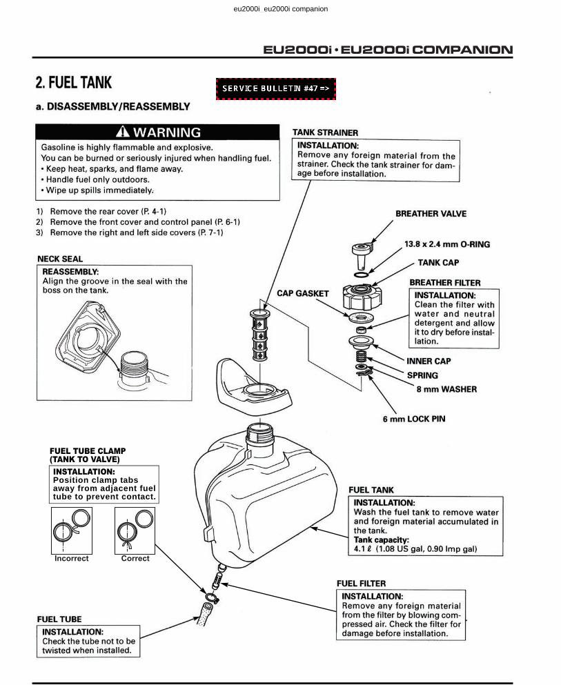
After cleaning, install the fuel tank and set the fuel strainer in the tank. Connect the fuel tube. Position fuel tube clamp tabs away from adjacent fuel tube to prevent contact.
FUEL TUBE CLAMP
Revised: October 2012 (PSV61Z0700E9)
eu2000i_eu2000i companion

Date of Issue: February 20013-8
EU2000i COMPANION
Check the fuel tube for deterioration, cracks and gasoline leakage.• If there is any abnormality in the fuel tube, replace the tube.• Position fuel tube clamp tabs away from adjacent fuel tubes to prevent contact.
FUEL TUBECLAMP
Revised: October 2012 (PSV61Z0700E9)
eu2000i_eu2000i companion

Date of Issue: February 20014-1
EU2000i COMPANION 4. MUFFLER
1. MUFFLER............................................ 4-1
eu2000i_eu2000i companion

Date of Issue: February 20014-2
EU2000i COMPANION
eu2000i_eu2000i companion
Date of Issue: February 20015-1
EU2000i COMPANION 5. AIR CLEANER/CARBURETOR
1. AIR CLEANER .................................... 5-1 2. CARBURETOR ....................................5-2
eu2000i_eu2000i companion

Date of Issue: February 20015-2
EU2000i COMPANION
P. 5-4
Revised: February 2010 (61Z0700E5-B)
eu2000i_eu2000i companion

Date of Issue: February 20015-3
EU2000i COMPANION
eu2000i_eu2000i companion

Date of Issue: February 20015-4
EU2000i COMPANION
Revised: May 2011 (61Z0700E7)
eu2000i_eu2000i companion

Date of Issue: February 20015-5
EU2000i COMPANION
• PILOT SCREW AND LIMITER CAP REPLACEMENT
Only remove the pilot screw and limiter cap when necessary for repair or for cleaning stubborn deposits from the pilot circuit passages.
Removal of the limiter cap requires breaking the pilot screw. A new pilot screw and limiter cap must be installed.
NOTICETampering is a violation of Federal and California law.
1. When the limiter cap has been broken off, remove the broken pilot screw.
2. Place the spring on the replacement pilot screw, and install it on the carburetor.
3. Turn the pilot screw in until it is lightly seated; then turn the screw out the required number of turns.
4. Apply Locktite® 638 to the inside of the new limiter cap, and then install the cap so its stop prevents the pilot screw from being turned counterclockwise.
Be careful to avoid turning the pilot screw while installing the limiter cap. The pilot screw must stay at its required set-ting.
• THROTTLE STOP SCREW
Install the throttle stop screw after installing the pilot jet.
1. Install so that the throttle valve is at the full close position and the screw end does not come out of the bracket.
2. Start the engine, turn the ECO throttle switch on. Wait until the engine warms up.
3. Turn the throttle stop screw in until the engine speed starts to increase: then turn the screw out 3/5 turns.
Pilot screw opening 2-5/8 turns out
Revised: May 2011 (61Z0700E7)
eu2000i_eu2000i companion

Date of Issue: February 20015-6
EU2000i COMPANION
eu2000i_eu2000i companion

Date of Issue: February 20016-1
EU2000i COMPANION 6. CONTROL PANEL
1. CONTROL PANEL
1. CONTROL PANEL .............................. 6-1
P. 2-21
EU2000i
eu2000i_eu2000i companion

Date of Issue: February 20016-2
EU2000i COMPANION
P. 6-6
P. 6-6
P. 6-5
P. 6-5
P. 6-5
Revised: October 2012 (PSV61Z0700E9)
eu2000i_eu2000i companion

Date of Issue: February 20016-3
EU2000i COMPANION
EU2000i Companion
5 x 10
6 x 15 mm SPECIALSCREW (4)
1. CONTROL PANELa. REMOVAL/INSTALLATION
1) Remove the four 5 x 16 mm tapping screws, and then disconnect the inverter unit harness that is connected to theinverter unit.
2) Remove the control panel assembly.3) Remove the 5 x 12 mm bolt and ground wire.
FRONT COVER
INVERTER UNIT
INVERTER UNIT HARNESS(INVERTER UNIT)
INSTALLATION: P. 2-1
5 x 16 mm TAPPINGSCREW (4)
5 x 12 (3)
PLAIN WASHER
6 mm SPRING NUT (4)
CONTROL PANELASSEMBLY
DISASSEMBLY/
REASSEMBLY: P. 6-2
P. 2-30
Revised: October 2012 (PSV61Z0700E9)

Date of Issue: February 20016-4
EU2000i COMPANION
CONTROLPANEL
ECO-THROTTLE SWITCH
b. DISASSEMBLY/REASSEMBLY
AC RECEPTACLE(125V - 30A)
INSPECTION: P. 6-3of the base shopmanual.
TERMINAL WIRE
REASSEMBLY: P. 2-1
HARNESS BAND
REASSEMBLY: P. 2-1
AC CIRCUITPROTECTOR (20A)
INSPECTION: P. 6-4of the base shopmanual.
FRAME GROUND(CONTROL WIRE HARNESS)
REASSEMBLY: P. 2-1
5 x 13 mmPAN SCREW
5 x 12 mmPAN SCREW(GROUNDTERMINAL)
5 x 8 mmPAN SCREW
NUT(AC CIRCUITPROTECTOR)
4 mmFLANGE NUT (4)
CONTROL WIRE HARNESS
REASSEMBLY: P. 2-1
IGNITION CONTROLMODULE
INSPECTION: P. 6-4of the base shopmanual.
AC RECEPTACLE(125V - 20A)
INSPECTION: P. 6-3of the base shopmanual.
INSTALLATION:
Install with the “ON” and “OFF”marks facing up.
INSPECTION: P. 6-3 of the baseshop manual.
PARALLELOPERATIONOUTLET (2)
MARK
P. 6-5
P. 6-6
P. 6-5
P. 6-5
P. 6-6
P. 2-30
P. 2-30
INSPECTION: P. 6-6
INSPECTION: P. 6-5
INSPECTION: P. 6-5
INSPECTION: P. 6-5
INSPECTION: P. 6-5
IGNITION CONTROLMODULE
P. 2-30
Revised: October 2012 (PSV61Z0700E9)

Date of Issue: February 20016-5
EU2000i COMPANION
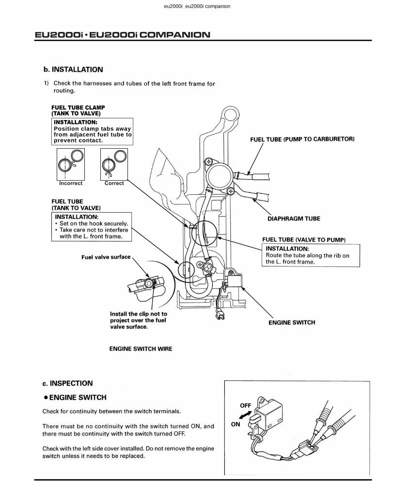
Check for continuity between the switch terminals.There must be no continuity with the switch turned ON, and continuity with the switch turned OFF.
eu2000i_eu2000i companion

Date of Issue: February 20016-6
EU2000i COMPANION
eu2000i_eu2000i companion

Date of Issue: February 20017-1
EU2000i COMPANION
7. SIDE COVERS/FUEL TANK/.........FRONT FRAMES/UNDER COVER
1. SIDE COVERS .................................... 7-1 3. FRONT FRAMES/UNDER COVER .....7-3
2. FUEL TANK......................................... 7-2
eu2000i_eu2000i companion
Date of Issue: February 20017-2
EU2000i COMPANION
Incorrect Correct
FUEL TUBE CLAMP(TANK TO VALVE)INSTALLATION:Position clamp tabs away from adjacent fuel tube to prevent contact.
Revised: October 2012 (PSV61Z0700E9)
eu2000i_eu2000i companion

Date of Issue: February 20017-3
EU2000i COMPANION
3. FRONT FRAMES/UNDER COVER
Revised: June 2010 (PSV61Z0700E6-A)
4.4 N•m (0.4 kg•f, 3.2 lbf•ft)
eu2000i_eu2000i companion
Date of Issue: February 20017-4
EU2000i COMPANION
P. 7-5
Revised: February 2010 (61Z0700E5-B)
eu2000i_eu2000i companion
Date of Issue: February 20017-5
EU2000i COMPANION
Incorrect Correct
FUEL TUBE CLAMP(TANK TO VALVE)INSTALLATION:Position clamp tabs away from adjacent fuel tube to prevent contact.
Revised: October 2012 (PSV61Z0700E9)
eu2000i_eu2000i companion

Date of Issue: February 20017-6
EU2000i COMPANION
eu2000i_eu2000i companion

Date of Issue: February 20018-1
EU2000i COMPANION 8. RECOIL STARTER/FAN COVER
1. RECOIL STARTER/FAN COVER........ 8-12. FAN SHROUD ..................................... 8-5
3. EXHAUST MANIFOLD/CARBURETOR INSULATOR ..............8-6
eu2000i_eu2000i companion

Date of Issue: February 20018-2
EU2000i COMPANION
eu2000i_eu2000i companion

Date of Issue: February 20018-3
EU2000i COMPANION
eu2000i_eu2000i companion

Date of Issue: February 20018-4
EU2000i COMPANION
eu2000i_eu2000i companion

Date of Issue: February 20018-5
EU2000i COMPANION
eu2000i_eu2000i companion

Date of Issue: February 20018-6
EU2000i COMPANION
eu2000i_eu2000i companion
Date of Issue: February 20019-1
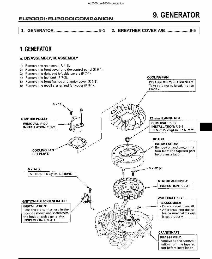
EU2000i COMPANION 9. GENERATOR
1. GENERATOR ...................................... 9-1 2. BREATHER COVER A/B.....................9-5
eu2000i_eu2000i companion

Date of Issue: February 20019-2
EU2000i COMPANION
eu2000i_eu2000i companion
Date of Issue: February 20019-3
EU2000i COMPANION
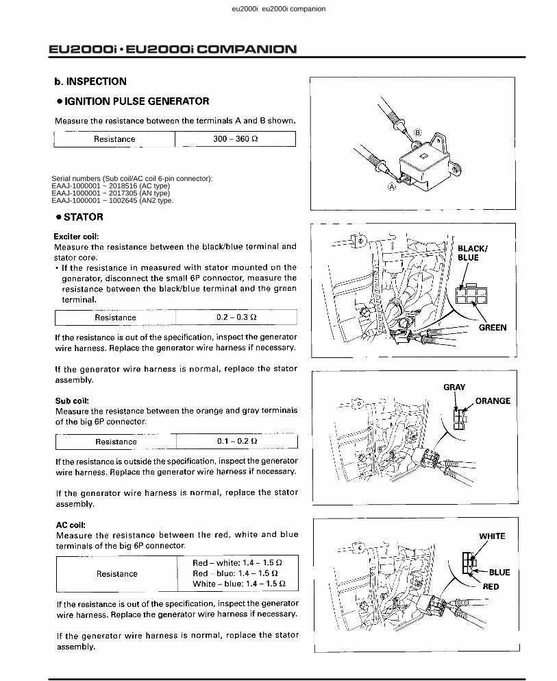
Serial numbers (Sub coil/AC coil 6-pin connector):EAAJ-1000001 ~ 2018516 (AC type)EAAJ-1000001 ~ 2017305 (AN type)EAAJ-1000001 ~ 1002645 (AN2 type.
Revised: June 2010 (PSV61Z0700E6-A)
eu2000i_eu2000i companion
Date of Issue: February 20019-4
EU2000i COMPANION
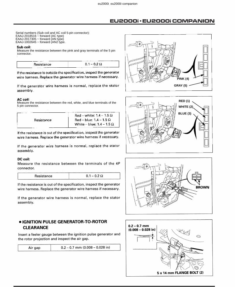
RED (1)
WHITE (2)
BLUE (3)
Measure the resistance between the pink and gray terminals of the 5 pin connector.
Measure the resistance between the red, white, and blue terminals of the 5 pin connector.
Serial numbers (Sub coil and AC coil 5-pin connector):EAAJ-2018516 ~ forward (AC type)EAAJ-2017305 ~ forward (AN type)EAAJ-1002645 ~ forward (AN2 type.
PINK (4)
GRAY (5)
Revised: June 2010 (PSV61Z0700E6-A)
eu2000i_eu2000i companion

Date of Issue: February 20019-5
EU2000i COMPANION
eu2000i_eu2000i companion

Date of Issue: February 20019-6
EU2000i COMPANION
eu2000i_eu2000i companion

Date of Issue: February 200110-1
EU2000i COMPANION
10. CAM PULLEY/CRANKSHAFT/PISTON/CYLINDER BLOCK
1. CAM PULLEY .................................... 10-1 5. GOVERNOR....................................... 10-14
2. CRANKCASE COVER/CRANKSHAFT/CYLINDER BLOCK.. 10-5
6. INSPECTION...................................... 10-177. VALVE GUIDE REPLACEMENT ....... 10-24
3. PISTON .............................................. 10-10 8. VALVE SEAT RECONDITIONING ..... 10-26
4. VALVES.............................................. 10-12
Revised: June 2008 (PSV61Z0700-4)
eu2000i_eu2000i companion

Date of Issue: February 200110-2
EU2000i COMPANION
eu2000i_eu2000i companion

Date of Issue: February 200110-3
EU2000i COMPANION
eu2000i_eu2000i companion

Date of Issue: February 200110-4
EU2000i COMPANION
eu2000i_eu2000i companion

Date of Issue: February 200110-5
EU2000i COMPANION
eu2000i_eu2000i companion

Date of Issue: February 200110-6
EU2000i COMPANION
eu2000i_eu2000i companion

Date of Issue: February 200110-7
EU2000i COMPANION
eu2000i_eu2000i companion

Date of Issue: February 200110-8
EU2000i COMPANION
eu2000i_eu2000i companion

Date of Issue: February 200110-9
EU2000i COMPANION
eu2000i_eu2000i companion

Date of Issue: February 200110-10
EU2000i COMPANION
eu2000i_eu2000i companion

Date of Issue: February 200110-11
EU2000i COMPANION
eu2000i_eu2000i companion

Date of Issue: February 200110-12
EU2000i COMPANION
eu2000i_eu2000i companion

Date of Issue: February 200110-13
EU2000i COMPANION
eu2000i_eu2000i companion

Date of Issue: February 200110-14
EU2000i COMPANIONEU2000i
Revised: February 2006 (PSV53351-B)
eu2000i_eu2000i companion

Date of Issue: February 200110-15
EU2000i COMPANION
eu2000i_eu2000i companion

Date of Issue: February 200110-16
EU2000i COMPANION
eu2000i_eu2000i companion

Date of Issue: February 200110-17
EU2000i COMPANION
eu2000i_eu2000i companion
Date of Issue: February 200110-18
EU2000i COMPANION
eu2000i_eu2000i companion

Date of Issue: February 200110-19
EU2000i COMPANION
eu2000i_eu2000i companion

Date of Issue: February 200110-20
EU2000i COMPANION
(P. 10-19).
Revised: February 2010 (61Z0700E5-B)
eu2000i_eu2000i companion
Date of Issue: February 200110-21
EU2000i COMPANION
eu2000i_eu2000i companion
Date of Issue: February 200110-22
EU2000i COMPANION
eu2000i_eu2000i companion
Date of Issue: February 200110-23
EU2000i COMPANION
eu2000i_eu2000i companion

Date of Issue: February 200110-24
EU2000i COMPANION
eu2000i_eu2000i companion
Date of Issue: February 200110-25
EU2000i COMPANION
eu2000i_eu2000i companion

Date of Issue: February 200110-26
EU2000i COMPANION
eu2000i_eu2000i companion

Date of Issue: February 200110-27
EU2000i COMPANION
eu2000i_eu2000i companion

Date of Issue: February 200110-28
EU2000i COMPANION
eu2000i_eu2000i companion

Revised: September 2008 (PSV61Z07005E)11-1
EU2000i COMPANION11. OPERATION
1. INVERTER TYPE GENERATORCONSTRUCTIONThe Inverter generator has an outer and an inner rotating set of magnets for both the generator and the ignition. The inner set of magnets generate AC in the stator windings, while the outer set generates AC for the ignition coil. A multi-pole coil is used on the stator (15 poles for the AC winding, 6 poles for the DC winding, 1 pole for the sub winding, and 1 pole for the exciter winding). The AC coil in the stator is picked up by the inverter.
Operating Principles
When the rotor rotates, the AC (3-phase) is generated at the AC main winding, which is converted into DC by the regulator/rectifier. The voltage is stabilized by the regulator/rectifier in the converter simultaneously. The AC generated at the sub winding becomes the power source for each circuit and elemental device, such as an inverter built-in power transistor. Getting a signal from the oscillator circuit, the inverter that controls the LED generates the AC (single phase) of the proper frequency.
• AC Overload Protection System
The power output indicator light (green LED) is on while the generator is running with normal load. When overloaded, the overload warning light turns on by getting signal from the output current detecting circuit to indicate overloading. When the generator runs overloaded for more than 5 seconds, the circuit cuts off the AC to protect the generator. When
1. INVERTER TYPE GENERATOR......... 11-12. FULL TRANSISTOR IGNITION .......... 11-2
3. ECO-THROTTLE(ELECTRICAL GOVERNOR) ..............11-3
4. INDICATORS .......................................11-4
eu2000i_eu2000i companion

Revised: September 2008 (PSV61Z07005E)11-2
EU2000i COMPANION
the output is cut off due to overloading, stop the engine and disconnect the attached electrical device from the generator to remove the load. Start the engine again. The LED (green) should turn on.
2. FULL TRANSISTOR IGNITION
Operating Principles
The positive (+) and negative (-) power sources are provided from the exciter winding. AC current is provided to the Ignition coil from the negative (-) power source. Current switching to the ignition coil is controlled by the Field Effect Transistor (FET).
The FET turns on when the pulse pole front end reaches the ignition pulse generator and starts to amplify the current in the ignition coil primary winding. The FET turns off when the pulse pole back end has passed the ignition pulse generator, which stops the current in the ignition coil primary winding. The high voltage is then generated in the ignition coil secondary winding (ignition point).
• Rev Limiter
The engine is equipped with a rev limiter to protect the generating system from excessive engine speed. The rev limiter receives its signal from the ignition pulse generator. If the engine speed reaches a predetermined level, the rev limiter will be activated and will cut off the ignition system.
• Oil Alert® System
The Oil Alert® unit will cut off the ignition system when the engine oil falls to a predetermined level by turning on the oil level switch and the red light emitting diode (LED), which acts as a warning light. The red LED will remain lit approximately two seconds after engine stops using electrical energy from the condenser in the ignition control module.
• Electrical Source
The engine is operated by the dual electrical source: the positive (+) half-wave and the negative (-) half-wave. The diodes convert AC that is generated at the exciter winding to the positive (+) half-wave and the negative (-) half-wave AC currents. The positive (+) half-wave becomes the power source for the rev limiter while the negative (-) half-wave becomes the power source for the ignition system and the Oil Alert® unit. Both of the half waves become the power source for the FET gate drive. This system realizes a stable rev limiter activating condition and a Field Effect Transistor (FET) ignition system.
eu2000i_eu2000i companion

Revised: September 2008 (PSV61Z07005E)11-3
EU2000i COMPANION
3. ECO-THROTTLE (ELECTRICAL GOVERNOR)
Operating Principles
• Variable Engine Speed
The inverter’s CPU compares the current output voltage, current and engine speed with what is programed it its memory and sets the throttle position accordingly. The actual required engine speed then is based on generator load ratio and temperature. As a load is applied, the engine speed, generator output power will drop momentarily. The inverter will calculate the type of load (how much of power drop is occurring) and set the engine speed accordingly.
• Engine Stall Prevention System
Detecting the engine load by the throttle opening the system prevents engine speed from going down when the load is excessively high, beyond engine load capacity by controlling the output voltage at the inverter. This system is able to generate maximum power more efficiently, and control peak performance for applications that require more electric power, such as motors. The system automatically activates higher engine speeds in order to compensate for the power loss of the engine when used in the high altitude or deterioration if the generator caused over time.
eu2000i_eu2000i companion

Revised: September 2008 (PSV61Z07005E)11-4
EU2000i COMPANION
4. INDICATORS
The green LED output indicator has a simplified hour meter function. It blinks when starting the generator, depending on thecumulative operating hours noted below.
After the hour meter function is complete, the output indicator light turns on/off, depending on the power generating status of the inverter.
<Blinking pattern of the hour meter when starting the generator>
<Output indicator status by power generating status>
OUTPUT INDICATOR (Green): BLINK/OFF at start
Generator start
Engine start
ON
ON
ON
ON
ON
Indicator
OFF
OFF
OFF
OFF
OFF
OFF
1 Blink
2 Blinks
3 Blinks
4 Blinks
5 Blinks
ON
ON OFF250 ms 125 ms
BLINKING PATTERN:
1) Operating hours < 100 hNo blinking at start
2)
3)
4)
5)
6)
Operating hours 100 < 200 h1 Blink at start
Operating hours 200 < 300 h2 Blinks at start
Operating hours 300 < 400 h3 Blinks at start
Operating hours 400 < 500 h4 Blinks at start
Operating hours 500 or more5 Blinks at start
Blinking cycle:
Steady light
Condition of generator Output indictorGenerating power ON
Stop generating power OFF
OUTPUT INDICATOR (GREEN)
Revised: June 2010 (PSV61Z0700E6-A)
eu2000i_eu2000i companion

Revised: September 2008 (PSV61Z07005E)11-5
EU2000i COMPANION
OVERLOAD INDICATOR (RED)The red LED overload indicator turns ON when there is an overload (in excess of 2.0 kVA), or if there is ashort circuit in a connected appliance. The overload indicator will stay ON, and after about four seconds, current to the connected appliance(s) will shut OFF, and the output indicator (green) will go OFF. However, the engine will continue to run.When a malfunction in the inverter is detected, it will blink.
<generator overload, error detection>
Condition of generator OVERLOAD INDICATOR
Detecting overload ON
Other than above OFF
OVERLOAD INDICATOR (Red):
OIL ALERT INDICATOR (RED)In case of insufficient engine oil level, the red LED oil alert indicator comes ON and ignition will be cut to stop the engine. Also, when engine oil is insufficient at start, it will prevent the engine from starting.
<Insufficient engine oil>
Condition of generator OIL ALERT INDICATOR OIL LEVEL SWITCH
Insufficient engine oil level during engine operation ON ON
Insufficient engine oil level when starting the engine ON ON
Other than above OFF OFF
OIL ALERTINDICATOR (Red):
Detecting error * ON
* “Detecting error” indicates that it is detecting either of the following: SCR element temperature abnormality, FET element temperature abnormality, excess voltage, or excess current.
Revised: June 2010 (PSV61Z0700E6-A)
eu2000i_eu2000i companion

Revised: September 2008 (PSV61Z07005E)11-6
EU2000i COMPANION
eu2000i_eu2000i companion