Embed Size (px)
Citation preview
Euphonix SH612 Studio Hub User Guide
Part Number: 840-07577-03
SH612 Version: 3.06
S5 Version: 2.5
R-1 Version: 3.0
Euphonix Inc.220 Portage Ave.Palo Alto, California 94306Phone: 650-855-0400Fax: 650-855-0410Web: http://www.euphonix.come-mail: [email protected]
Word 48000 0.000% Locked
LTC 00:01:52:43 Jam Cont
96
CUSTOM
44.1
48
PULL UP
DUAL REF
PULL DOWN
AES
WORD
VIDEO SYNC
INTERNAL
VIDEO
TC LOCK
OTHER
SH
612
STUDIO HUB
1 2 3 4 5 6
7 8 9 10 11 12
M A D I
Info Escape Select
In the interest of continued product development, Euphonix reserves the right to make improvements in this manual and the product it describes at any time, without notice or obligation.
System 5, S-5, PatchNet, eMix, EuCon, R-1, Audio Deck, Studio Hub are trademarks of Euphonix Inc.
©2001 Euphonix Inc. All rights reserved worldwide. No part of this publication may be reproduced, transmitted, transcribed, stored in a retrieval system, or translated into any language in any form by any means without written permission of Euphonix Inc.
Euphonix SH612 Studio Hub User Guide
iii
Table of ContentsList of Figures ....................................................................................................................... iv
Chapter 1: Getting Started ....................................................................................................5
1.1 Introduction to the SH612............................................................................51.1.1 Features ............................................................................................51.1.2 Power On Sequence .........................................................................6
1.2 MADI Connections for the R-1 ...................................................................6
1.3 AES Sync.....................................................................................................7
Chapter 2: Front and Rear Panel Interface..............................................................11
2.1 Front Panel .................................................................................................112.1.1 LCD Display ..................................................................................112.1.2 Menu Controls................................................................................122.1.3 Sample Rate Controls/Indicators ...................................................132.1.4 MADI Indicators ............................................................................15
2.2 Rear Panel Connectors...............................................................................16
Chapter 3: Menu Reference and Technical Specifications .........................19
3.1 Menu Reference .........................................................................................193.1.1 Quick Setup Menu .........................................................................203.1.2 Sample Rate Setup Menu...............................................................213.1.3 Time Code Setup Menu .................................................................223.1.4 Video Setup Menu .........................................................................253.1.5 MADI Routing Menu.....................................................................273.1.6 Utility Menu...................................................................................293.1.7 Transport ........................................................................................30
3.2 SH612 Technical Specifications ................................................................31
Euphonix SH612 Studio Hub User Guide
iv
List of Figures
1-1 AES sync connections for the SH612 .................................................................................7
2-1 SH612 Front Panel ............................................................................................................11
2-2 LCD Display .....................................................................................................................11
2-3 LCD Menu Display ...........................................................................................................12
2-4 Menu Controls on Front Panel ..........................................................................................12
2-5 Sample Rate LEDs and Buttons ........................................................................................14
2-6 MADI Buttons ..................................................................................................................15
2-7 SH612 Rear Panel .............................................................................................................16
3-1 Main Menu ........................................................................................................................19
3-2 Quick Setup Menu ............................................................................................................20
3-3 Sample Rate Setup Menu ..................................................................................................21
3-4 Time Code Setup Menu ....................................................................................................22
3-5 Video Setup Menu ............................................................................................................25
3-6 MADI Routing Menu ........................................................................................................27
3-7 Utility Menu ......................................................................................................................29
Euphonix SH612 Studio Hub User Guide
Chapter 1: Getting Started
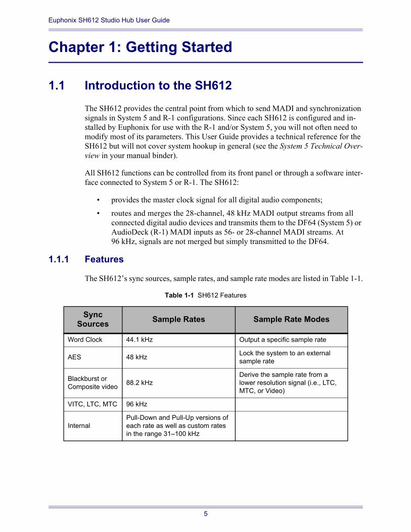
1.1 Introduction to the SH612The SH612 provides the central point from which to send MADI and synchronization signals in System 5 and R-1 configurations. Since each SH612 is configured and in-stalled by Euphonix for use with the R-1 and/or System 5, you will not often need to modify most of its parameters. This User Guide provides a technical reference for the SH612 but will not cover system hookup in general (see the System 5 Technical Over-view in your manual binder).
All SH612 functions can be controlled from its front panel or through a software inter-face connected to System 5 or R-1. The SH612:
provides the master clock signal for all digital audio components;
routes and merges the 28-channel, 48 kHz MADI output streams from all connected digital audio devices and transmits them to the DF64 (System 5) or AudioDeck (R-1) MADI inputs as 56- or 28-channel MADI streams. At 96 kHz, signals are not merged but simply transmitted to the DF64.
1.1.1 Features
The SH612s sync sources, sample rates, and sample rate modes are listed in Table 1-1.
Table 1-1 SH612 Features
Sync Sources Sample Rates Sample Rate Modes
Word Clock 44.1 kHz Output a specific sample rate
AES 48 kHz Lock the system to an external sample rate
Blackburst or Composite video 88.2 kHz
Derive the sample rate from a lower resolution signal (i.e., LTC, MTC, or Video)
VITC, LTC, MTC 96 kHz
InternalPull-Down and Pull-Up versions of each rate as well as custom rates in the range 31100 kHz
5
Euphonix SH612 Studio Hub User Guide Getting Started
Synchronization signals are distributed via four AES Sync (AES/EBU), Word Clock, video, or MTC outputs to System 5 or R-1 components. The SH612 can generate or lock to Time code, or convert between different formats. All standard time code rates are supported:
Film: 24 fps
PAL/SECAM: 25 fps
Color NTSC: 29.97 (drop and non-drop)
black and white video rate
MIDI sequencers: 30 fps (drop and non-drop)
The SH612 routes digital audio via 12 MADI In and 12 MADI Out ports, each with the capacity to receive or transmit up to 56 channels (up to 24-bit, 48 kHz). For sample rates exceeding 50 kHz, each MADI channel can carry only 28 digital audio channels.
1.1.2 Power On Sequence
Attach the provided IEC-compatible power cable to the IEC inlet. Connect the other end to a wall outlet with appropriate plug adapter if necessary. The SH612 power sup-ply automatically adjusts to any voltage in the range 110240 V.
We recommend powering up the SH612 before the digital devices to which it is con-nected. The SH612 conducts a brief self-test routine upon power-up and displays the firmware revision number. When the Main Menu is displayed, power up the attached converters.
NOTE: Please refer to the power up routine for System 5 before attempting to power the DF64 Digital Frames and the Pilot Computers.
1.2 MADI Connections for the R-1These are the standard MADI connections for the R-1:
MADI Ports 14 are for converter or I/O devices
MADI Port 7 is for AudioDeck 1
MADI Port 8 is for AudioDeck 2
MADI Port 9 is for AudioDeck 3
MADI Port 10 is for AudioDeck 4
MADI Ports 5, 6, 11, and 12 are for additional MADI devices that require a custom route to be used with the R-1 (see Section 3.1.5 - MADI Routing Menu).
6
Euphonix SH612 Studio Hub User Guide Getting Started
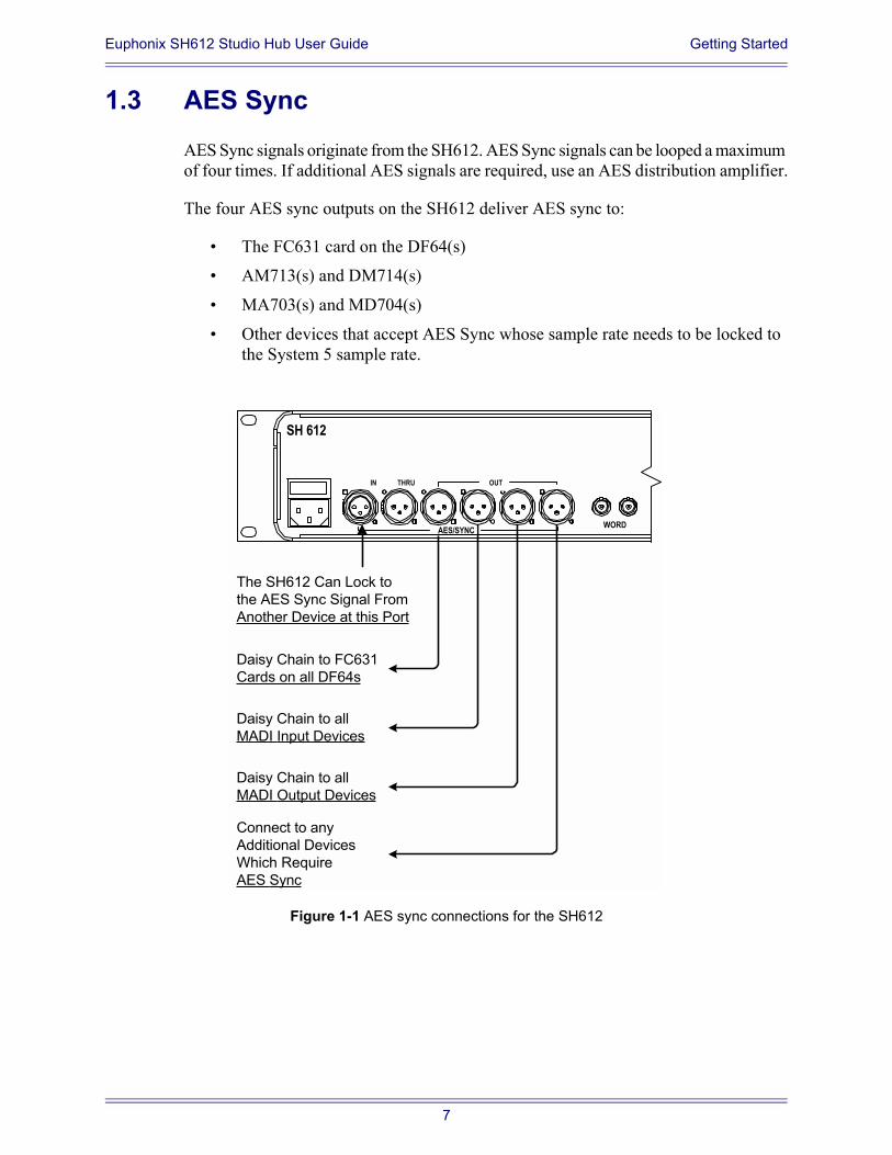
1.3 AES SyncAES Sync signals originate from the SH612. AES Sync signals can be looped a maximum of four times. If additional AES signals are required, use an AES distribution amplifier.
The four AES sync outputs on the SH612 deliver AES sync to:
The FC631 card on the DF64(s)
AM713(s) and DM714(s)
MA703(s) and MD704(s)
Other devices that accept AES Sync whose sample rate needs to be locked to the System 5 sample rate.
Figure 1-1 AES sync connections for the SH612
Daisy Chain to FC631Cards on all DF64s
Daisy Chain to allMADI Input Devices
Daisy Chain to allMADI Output Devices
Connect to anyAdditional DevicesWhich RequireAES Sync
The SH612 Can Lock tothe AES Sync Signal FromAnother Device at this Port
THRU
AES/SYNC
SH 612
IN OUT
WORD
7
Euphonix SH612 Studio Hub User Guide Getting Started
Make the following AES Sync connections:
Attach the provided XLR-to-Lemo cable from one of the AES Sync Out con-nectors on the SH612 to the AES Sync In connector on the FC631 card of the first DF64.
Attach the provided Lemo-to-Lemo cable from one of the AES Sync Out ports on the first DF64 to the FC631 card of the second DF64 (if present). Daisy chain this connection to additional DF64s.
Attach the provided yellow XLR cable from one of the AES Sync Out connectors on the SH612 to the AES Sync In of the AM713 or DM714. Daisy chain this connection to other AM713(s), DM714(s), MD704, or other digital devices with an AES Sync input.
Attach the provided yellow XLR cable from one of the AES Sync Out connectors on the SH612 to the AES Sync In of the MA703 or MD704. Daisy chain this connection to other MA703(s) or MD704(s).
Attach the provided yellow XLR cable from one of the AES Sync Out connectors on the SH612 to the AES Sync In of other devices with AES Sync inputs whose sample clocks must be locked to System 5 (i.e., the R-1).
The Word Clock output of the SH612 can also be used to sync to an external device or group of devices using daisy chain cabling.
NOTE: The AES Thru port on the Euphonix converters is always active. If daisy chained de-vices are powered off, downstream devices will lose sync.
8

Euphonix SH612 Studio Hub User Guide Getting Started
9

Euphonix SH612 Studio Hub User Guide Front and Rear Panel Interface
Chapter 2: Front and Rear Panel Interface
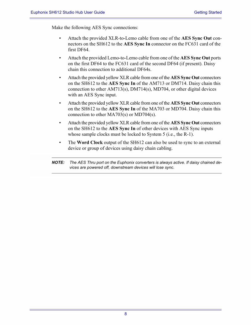
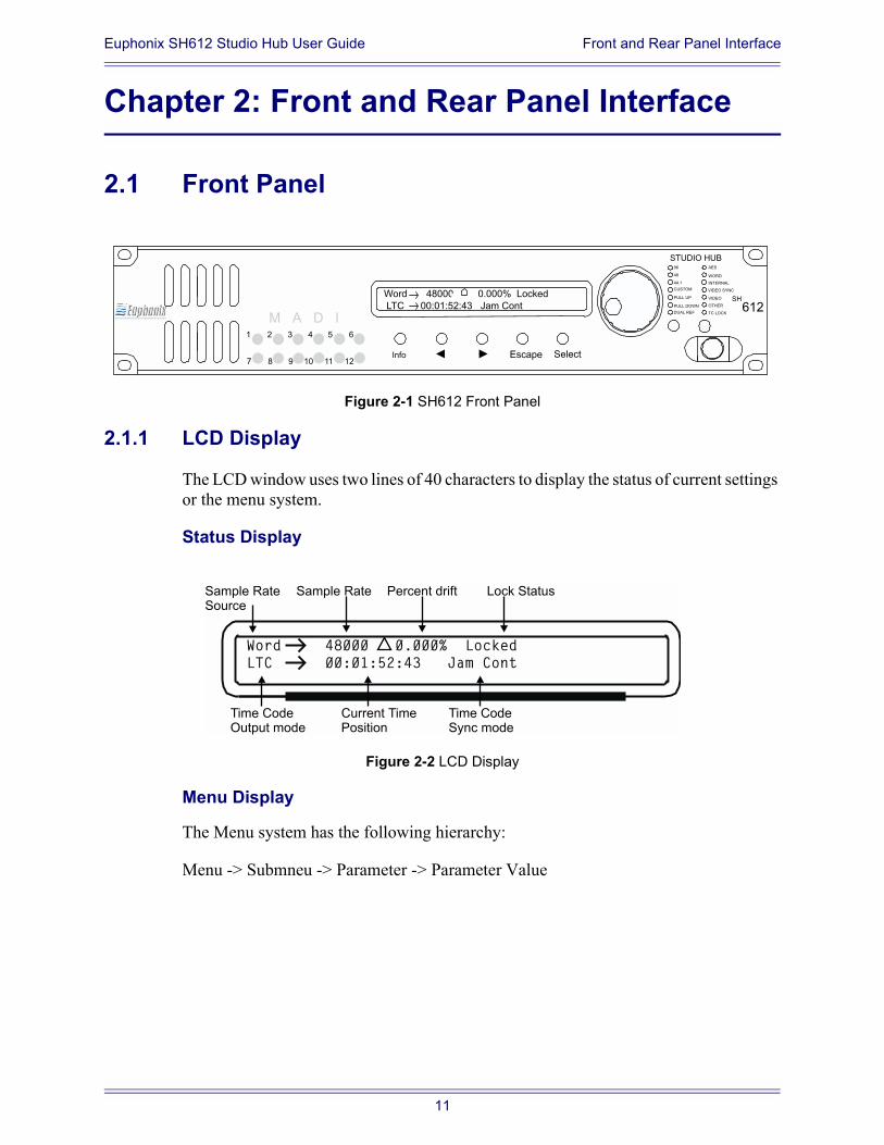
2.1 Front Panel
Figure 2-1 SH612 Front Panel
2.1.1 LCD Display
The LCD window uses two lines of 40 characters to display the status of current settings or the menu system.
Status Display
Figure 2-2 LCD Display
Menu Display
The Menu system has the following hierarchy:
Menu -> Submneu -> Parameter -> Parameter Value
Word 48000 0.000% Locked
LTC 00:01:52:43 Jam Cont
96
CUSTOM
44.1
48
PULL UP
DUAL REF
PULL DOWN
AES
WORD
VIDEO SYNC
INTERNAL
VIDEO
TC LOCK
OTHER
SH
612
STUDIO HUB
1 2 3 4 5 6
7 8 9 10 11 12
M A D I
Info Escape Select
Word 48000 0.000% Locked
LTC 00:01:52:43 Jam Cont
Sample RateSource
Time CodeOutput mode
Sample Rate
Current TimePosition
Percent drift Lock Status
Time CodeSync mode
11
Euphonix SH612 Studio Hub User Guide Front and Rear Panel Interface
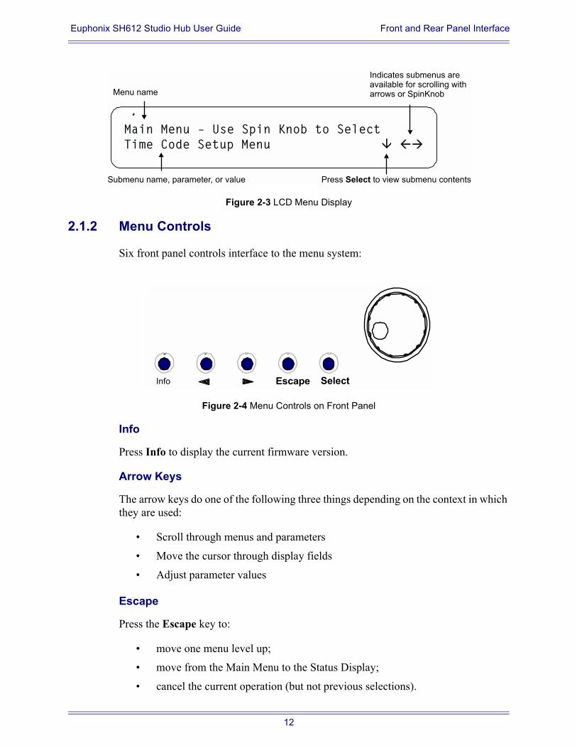
Figure 2-3 LCD Menu Display
2.1.2 Menu Controls
Six front panel controls interface to the menu system:
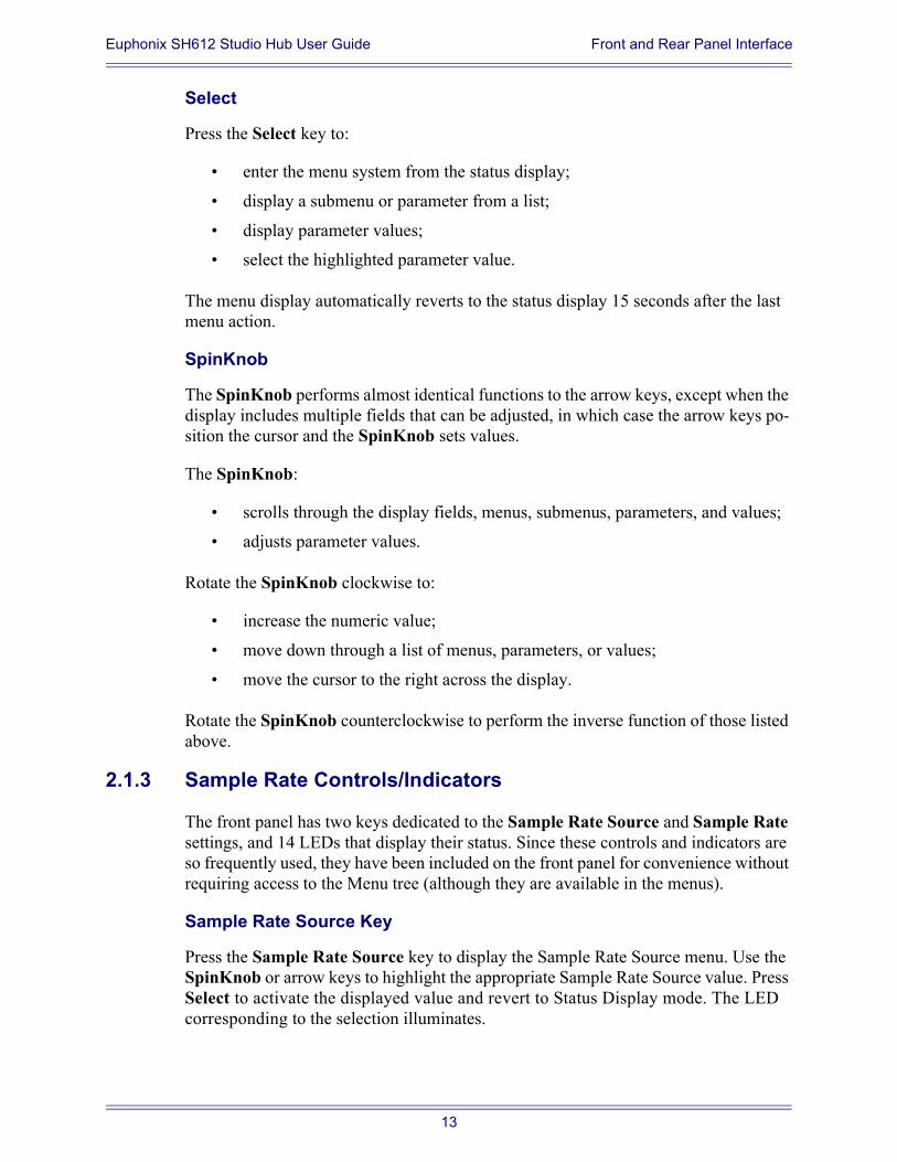
Figure 2-4 Menu Controls on Front Panel
Info
Press Info to display the current firmware version.
Arrow Keys
The arrow keys do one of the following three things depending on the context in which they are used:
Scroll through menus and parameters
Move the cursor through display fields
Adjust parameter values
Escape
Press the Escape key to:
move one menu level up;
move from the Main Menu to the Status Display;
cancel the current operation (but not previous selections).
Main Menu – Use Spin Knob to Select
Time Code Setup Menu
Menu name
Submenu name, parameter, or value
Indicates submenus areavailable for scrolling witharrows or SpinKnob
Press to view submenu contentsSelect
Info Escape Select
12
Euphonix SH612 Studio Hub User Guide Front and Rear Panel Interface
Select
Press the Select key to:
enter the menu system from the status display;
display a submenu or parameter from a list;
display parameter values;
select the highlighted parameter value.
The menu display automatically reverts to the status display 15 seconds after the last menu action.
SpinKnob
The SpinKnob performs almost identical functions to the arrow keys, except when the display includes multiple fields that can be adjusted, in which case the arrow keys po-sition the cursor and the SpinKnob sets values.
The SpinKnob:
scrolls through the display fields, menus, submenus, parameters, and values;
adjusts parameter values.
Rotate the SpinKnob clockwise to:
increase the numeric value;
move down through a list of menus, parameters, or values;
move the cursor to the right across the display.
Rotate the SpinKnob counterclockwise to perform the inverse function of those listed above.
2.1.3 Sample Rate Controls/Indicators
The front panel has two keys dedicated to the Sample Rate Source and Sample Rate settings, and 14 LEDs that display their status. Since these controls and indicators are so frequently used, they have been included on the front panel for convenience without requiring access to the Menu tree (although they are available in the menus).
Sample Rate Source Key
Press the Sample Rate Source key to display the Sample Rate Source menu. Use the SpinKnob or arrow keys to highlight the appropriate Sample Rate Source value. Press Select to activate the displayed value and revert to Status Display mode. The LED corresponding to the selection illuminates.
13
Euphonix SH612 Studio Hub User Guide Front and Rear Panel Interface
Sample Rate Key
Press the Sample Rate key to display the Sample Rate menu. Use the SpinKnob or arrow keys to highlight the desired Sample Rate setting. Press Select to activate the displayed value and revert to Status Display mode. The LED corresponding to the se-lection illuminates.
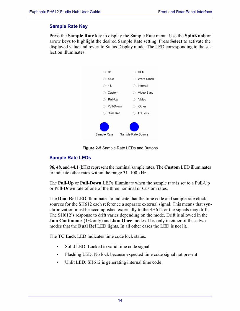
Figure 2-5 Sample Rate LEDs and Buttons
Sample Rate LEDs
96, 48, and 44.1 (kHz) represent the nominal sample rates. The Custom LED illuminates to indicate other rates within the range 31100 kHz.
The Pull-Up or Pull-Down LEDs illuminate when the sample rate is set to a Pull-Up or Pull-Down rate of one of the three nominal or Custom rates.
The Dual Ref LED illuminates to indicate that the time code and sample rate clock sources for the SH612 each reference a separate external signal. This means that syn-chronization must be accomplished externally to the SH612 or the signals may drift. The SH612s response to drift varies depending on the mode. Drift is allowed in the Jam Continuous (1% only) and Jam Once modes. It is only in either of these two modes that the Dual Ref LED lights. In all other cases the LED is not lit.
The TC Lock LED indicates time code lock status:
Solid LED: Locked to valid time code signal
Flashing LED: No lock because expected time code signal not present
Unlit LED: SH612 is generating internal time code
Sample Rate
44.1
48.0
96
Pull-Up
Dual Ref
Custom Video Sync
Sample Rate Source
Video
AES
Word Clock
TC Lock
Other
Internal
Pull-Down
14
Euphonix SH612 Studio Hub User Guide Front and Rear Panel Interface
2.1.4 MADI Indicators
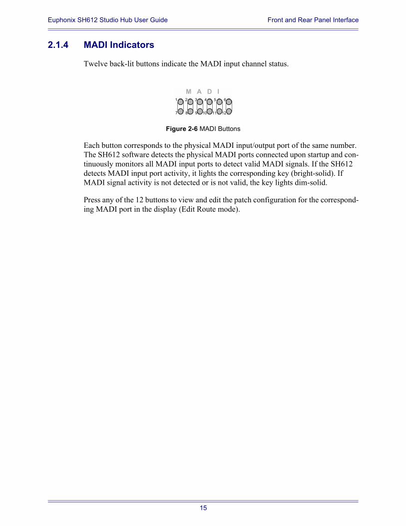
Twelve back-lit buttons indicate the MADI input channel status.
Figure 2-6 MADI Buttons
Each button corresponds to the physical MADI input/output port of the same number. The SH612 software detects the physical MADI ports connected upon startup and con-tinuously monitors all MADI input ports to detect valid MADI signals. If the SH612 detects MADI input port activity, it lights the corresponding key (bright-solid). If MADI signal activity is not detected or is not valid, the key lights dim-solid.
Press any of the 12 buttons to view and edit the patch configuration for the correspond-ing MADI port in the display (Edit Route mode).
1 2 3 4 5 6
7 8 9 10 11 12
M A D I
15
Euphonix SH612 Studio Hub User Guide Front and Rear Panel Interface
2.2 Rear Panel Connectors
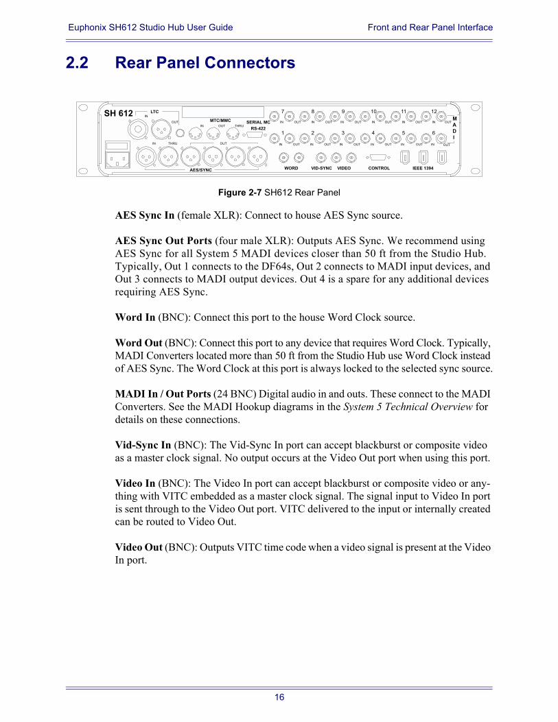
Figure 2-7 SH612 Rear Panel
AES Sync In (female XLR): Connect to house AES Sync source.
AES Sync Out Ports (four male XLR): Outputs AES Sync. We recommend using AES Sync for all System 5 MADI devices closer than 50 ft from the Studio Hub. Typically, Out 1 connects to the DF64s, Out 2 connects to MADI input devices, and Out 3 connects to MADI output devices. Out 4 is a spare for any additional devices requiring AES Sync.
Word In (BNC): Connect this port to the house Word Clock source.
Word Out (BNC): Connect this port to any device that requires Word Clock. Typically, MADI Converters located more than 50 ft from the Studio Hub use Word Clock instead of AES Sync. The Word Clock at this port is always locked to the selected sync source.
MADI In / Out Ports (24 BNC) Digital audio in and outs. These connect to the MADI Converters. See the MADI Hookup diagrams in the System 5 Technical Overview for details on these connections.
Vid-Sync In (BNC): The Vid-Sync In port can accept blackburst or composite video as a master clock signal. No output occurs at the Video Out port when using this port.
Video In (BNC): The Video In port can accept blackburst or composite video or any-thing with VITC embedded as a master clock signal. The signal input to Video In port is sent through to the Video Out port. VITC delivered to the input or internally created can be routed to Video Out.
Video Out (BNC): Outputs VITC time code when a video signal is present at the Video In port.
THRU
AES/SYNC
SH 612
1 2 3 4 5 6
7 8 9 10 11 12
IN IN IN IN IN INOUT OUT OUT OUT OUT
IN IN IN IN IN INOUT OUT OUT OUT OUT OUT
M
A
D
I
CONTROL IEEE 1394VIDEOVID-SYNCWORD
IN OUT
LTCIN
OUT
IN OUT THRUSERIAL MC
RS-422
MTC/MMC OUT
16
Euphonix SH612 Studio Hub User Guide Front and Rear Panel Interface
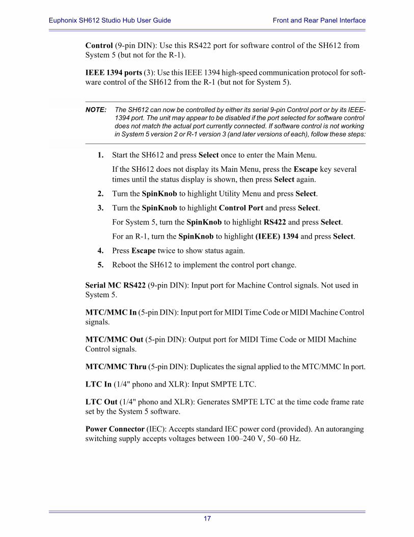
Control (9-pin DIN): Use this RS422 port for software control of the SH612 from System 5 (but not for the R-1).
IEEE 1394 ports (3): Use this IEEE 1394 high-speed communication protocol for soft-ware control of the SH612 from the R-1 (but not for System 5).
NOTE: The SH612 can now be controlled by either its serial 9-pin Control port or by its IEEE-1394 port. The unit may appear to be disabled if the port selected for software control does not match the actual port currently connected. If software control is not working in System 5 version 2 or R-1 version 3 (and later versions of each), follow these steps:
1. Start the SH612 and press Select once to enter the Main Menu.
If the SH612 does not display its Main Menu, press the Escape key several times until the status display is shown, then press Select again.
2. Turn the SpinKnob to highlight Utility Menu and press Select.
3. Turn the SpinKnob to highlight Control Port and press Select.
For System 5, turn the SpinKnob to highlight RS422 and press Select.
For an R-1, turn the SpinKnob to highlight (IEEE) 1394 and press Select.
4. Press Escape twice to show status again.
5. Reboot the SH612 to implement the control port change.
Serial MC RS422 (9-pin DIN): Input port for Machine Control signals. Not used in System 5.
MTC/MMC In (5-pin DIN): Input port for MIDI Time Code or MIDI Machine Control signals.
MTC/MMC Out (5-pin DIN): Output port for MIDI Time Code or MIDI Machine Control signals.
MTC/MMC Thru (5-pin DIN): Duplicates the signal applied to the MTC/MMC In port.
LTC In (1/4" phono and XLR): Input SMPTE LTC.
LTC Out (1/4" phono and XLR): Generates SMPTE LTC at the time code frame rate set by the System 5 software.
Power Connector (IEC): Accepts standard IEC power cord (provided). An autoranging switching supply accepts voltages between 100240 V, 5060 Hz.
17

Euphonix SH612 Studio Hub User Guide
Chapter 3: Menu Reference and Technical Specifications
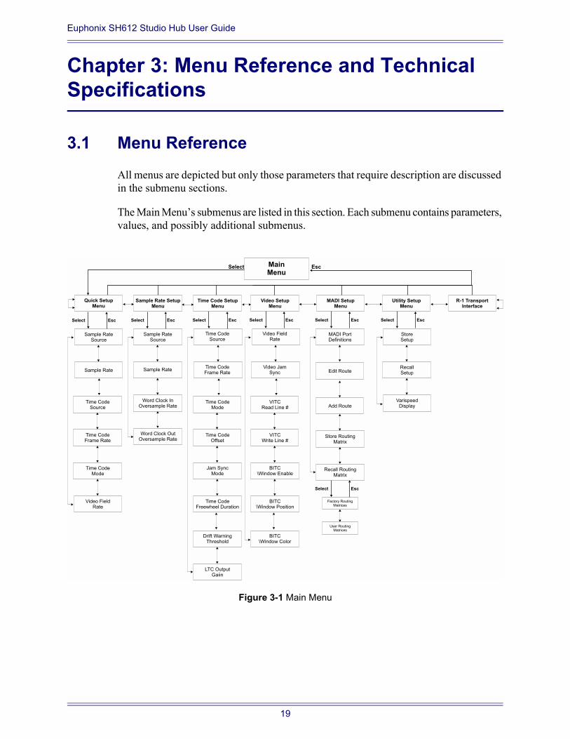
3.1 Menu ReferenceAll menus are depicted but only those parameters that require description are discussed in the submenu sections.
The Main Menus submenus are listed in this section. Each submenu contains parameters, values, and possibly additional submenus.
Figure 3-1 Main Menu
MainMenu
Sample Rate SetupMenu
Time Code SetupMenu
MADI SetupMenu
Sample RateSource
Sample RateSource
Sample Rate Sample Rate
Word Clock InOversample Rate
Word Clock OutOversample Rate
Quick SetupMenu
Select
Select SelectSelect Select
Esc
Esc EscEsc Esc
Video SetupMenu
Select Esc
Utility SetupMenu
Select Esc
R-1 TransportInterface
Time CodeSource
Time CodeFrame Rate
Time CodeMode
Video FieldRate
Time CodeSource
Time CodeFrame Rate
Time CodeOffset
Time CodeFreewheel Duration
Time CodeMode
Jam SyncMode
LTC OutputGaiin
Drift WarningThreshold
Video FieldRate
Video JamSync
VITCWrite Line #
BITC\Window Position
VITCRead Line #
BITC\Window Enable
BITC\Window Color
MADI PortDefinitions
Add Route
Store RoutingMatrix
Recall RoutingMatrix
Select Esc
Factory RoutingMatrices
User RoutingMatrices
StoreSetup
RecallSetup
VarispeedDisplay
Edit Route
19
Euphonix SH612 Studio Hub User Guide Menu Reference and Technical Specifications
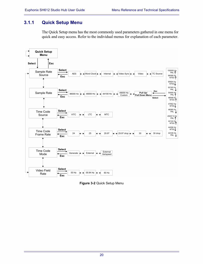
3.1.1 Quick Setup Menu
The Quick Setup menu has the most commonly used parameters gathered in one menu for quick and easy access. Refer to the individual menus for explanation of each parameter.
Figure 3-2 Quick Setup Menu
Sample RateSource
AES
Sample Rate
Quick SetupMenu
Select
Select
Esc
Esc
Time CodeSource
Time CodeFrame Rate
Time CodeMode
Video FieldRate
Word Clock Internal Video Sync Video TC Source
96000 Hz
Select
Esc48000 Hz 44100 Hz
49000 HzCustom
Pull Up/Pull Down Menu
VITC
Select
EscLTC MTC
24
Select
Esc25 29.97 29.97 drop 30 30 drop
Generate
Select
EscExternal
ExternalVarispeed
50 Hz
Select
Esc59.94 Hz 60 Hz
Select
Esc
100000 HzPAL
96096 HzNTSC
95904 HzNTSC
92160 HzPAL
50000 HzPAL
48048 HzNTSC
47952 HzNTSC
46080 HzPAL
45937.5 HzPAL
44144 HzNTSC
44056 HzNTSC
42336 HzPAL
20
Euphonix SH612 Studio Hub User Guide Menu Reference and Technical Specifications
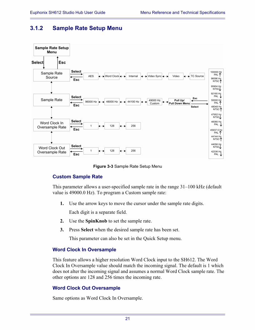
3.1.2 Sample Rate Setup Menu
Figure 3-3 Sample Rate Setup Menu
Custom Sample Rate
This parameter allows a user-specified sample rate in the range 31100 kHz (default value is 49000.0 Hz). To program a Custom sample rate:
1. Use the arrow keys to move the cursor under the sample rate digits.
Each digit is a separate field.
2. Use the SpinKnob to set the sample rate.
3. Press Select when the desired sample rate has been set.
This parameter can also be set in the Quick Setup menu.
Word Clock In Oversample
This feature allows a higher resolution Word Clock input to the SH612. The Word Clock In Oversample value should match the incoming signal. The default is 1 which does not alter the incoming signal and assumes a normal Word Clock sample rate. The other options are 128 and 256 times the incoming rate.
Word Clock Out Oversample
Same options as Word Clock In Oversample.
Sample Rate SetupMenu
Sample RateSource
Sample Rate
Word Clock InOversample Rate
Word Clock OutOversample Rate
Select Esc
AES
Select
EscWord Clock Internal Video Sync Video TC Source
96000 Hz
Select
Esc48000 Hz 44100 Hz
49000 HzCustom
Pull Up/Pull Down Menu
Select
Esc
100000 HzPAL
96096 HzNTSC
95904 HzNTSC
92160 HzPAL
50000 HzPAL
48048 HzNTSC
47952 HzNTSC
46080 HzPAL
45937.5 HzPAL
44144 HzNTSC
44056 HzNTSC
42336 HzPAL
1
Select
Esc128 256
1
Select
Esc128 256
21
Euphonix SH612 Studio Hub User Guide Menu Reference and Technical Specifications
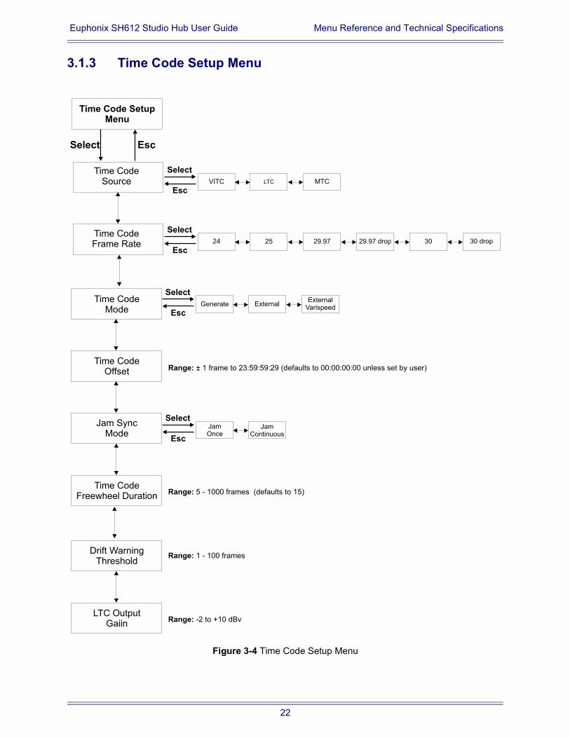
3.1.3 Time Code Setup Menu
Figure 3-4 Time Code Setup Menu
Time Code SetupMenu
Select Esc
Time CodeSource
Time CodeFrame Rate
Time CodeOffset
Time CodeFreewheel Duration
Time CodeMode
Jam SyncMode
LTC OutputGaiin
Drift WarningThreshold
VITC
Select
EscLTC MTC
24
Select
Esc25 29.97 29.97 drop 30 30 drop
Generate
Range: ± 1 frame to 23:59:59:29 (defaults to 00:00:00:00 unless set by user)
Select
EscExternal
ExternalVarispeed
JamOnce
Select
Esc
JamContinuous
Range: 5 - 1000 frames (defaults to 15)
Range: 1 - 100 frames
Range: -2 to +10 dBv
22
Euphonix SH612 Studio Hub User Guide Menu Reference and Technical Specifications
Time Code Mode
The SH612 has three time code outputs: VITC, LTC, MTC. The time code outputs al-ways represent the current time of the SH612.
Generate - This is the default mode for the SH612. Time code is internally generated, routed to the time code outputs, and sample-rate-resolved.
External - With this setting the SH612 is locked to an external time code source and generates the received time code position information at its outputs. This setting corre-sponds to the Slave key on the R-1 Remote.
External Varispeed - This feature is available only on SH612s configured for R-1 systems.
Time Code Offset
Time Code Offset is only relevant when the SH612 is slaved to an external device or an external device is slaved via LTC from the R-1. The R-1 does not output offset Time-code. The Time Code Offset can be positive or negative, and range from 1 frame to 23:59:59:29. A negative offset is subtracted from the Time Code Source value; a posi-tive Offset is added to the Time Code Source value. The equation for Current Time is:
TC Current Time = TC Source +/- TC Offset
The Time Code Offset defaults to 00:00:00:00 unless specifically set by the user.
To set the offset:
1. Use the left/right arrow keys to position the cursor under each of four double-digit fields.
2. Use the SpinKnob to set the desired number.
3. To create a negative offset, position the cursor under the + sign and use the SpinKnob to change to the minus sign.
Jam Sync Mode
Jam Once - Locks when time code is first received and runs independent of incoming time code thereafter.
Jam Continuous - Locks continuously to incoming time code and resynchronizes whenever necessary.
23
Euphonix SH612 Studio Hub User Guide Menu Reference and Technical Specifications
Time Code Free Wheel Duration
When the incoming time code signal is interrupted, the SH612 continues to generate time code while it checks for the resumption of incoming time code within the period specified in the Time Code Freewheel Duration setting. If the time code source re-sumes before the Time Code Freewheel Duration, the SH612 checks to see if the dif-ference between the current time code source frame value and the time code output frame value is within 1% deviation.
If the difference is less than or equal to 1%, the SH612 resynchronizes to the new time code source without interrupting time code or sample rate lock.
If the difference exceeds 1%, the SH612 drops time code and sample rate lock and locks to the new time code position.
Drift Warning Threshold
Specifies the amount of drift that triggers the drift warning (1100 frames).
LTC Output Gain
Specifies the output level of LTC in the range -2 to +10 dBv.
24
Euphonix SH612 Studio Hub User Guide Menu Reference and Technical Specifications
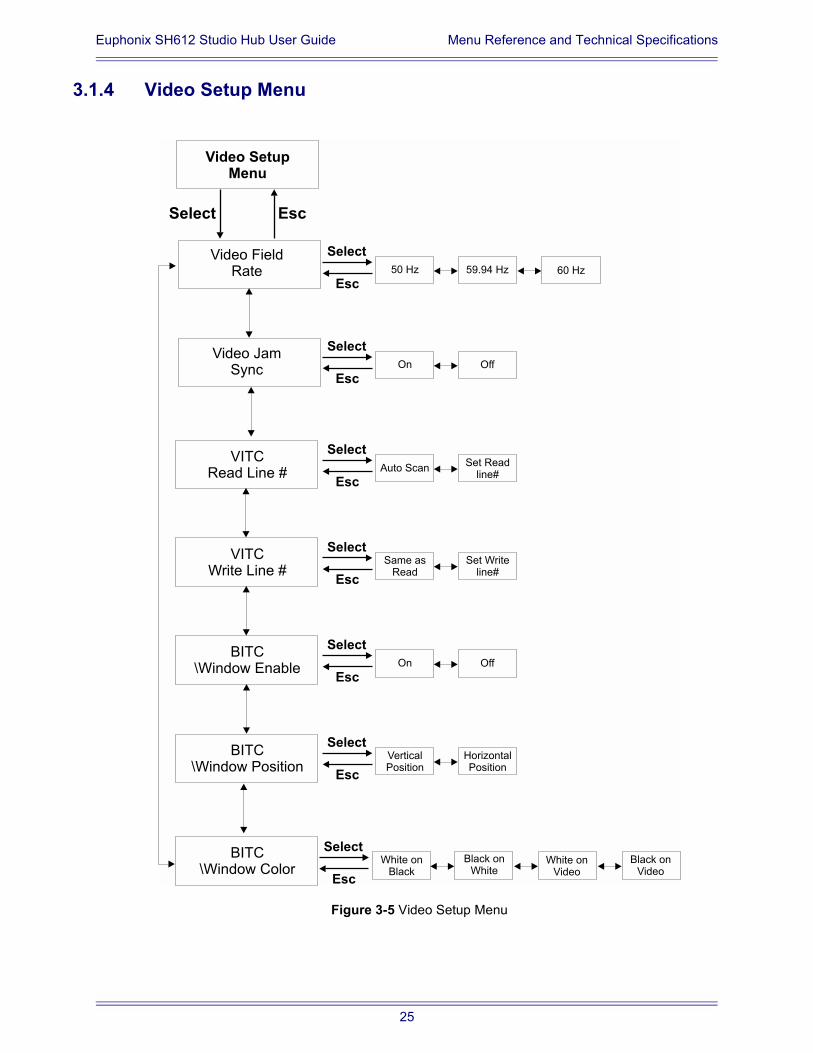
3.1.4 Video Setup Menu
Figure 3-5 Video Setup Menu
Video SetupMenu
Select Esc
Video FieldRate
Video JamSync
VITCWrite Line #
BITC\Window Position
VITCRead Line #
BITC\Window Enable
BITC\Window Color
50 Hz
Select
Esc59.94 Hz 60 Hz
On
Select
EscOff
Auto Scan
Select
Esc
Set Readline#
Same asRead
Select
Esc
Set Writeline#
On
Select
EscOff
VerticalPosition
Select
Esc
HorizontalPosition
White onBlack
Black onWhite
White onVideo
Black onVideo
Select
Esc
25
Euphonix SH612 Studio Hub User Guide Menu Reference and Technical Specifications
Video Jam Sync
On - The SH612 automatically jams the start of the LTC and MTC output frames to be aligned to line 5, field 0 of the blackburst, composite video, or VITC signal.
Off - The time code outputs are not frame-edge aligned with line 5 field 0 of the video source.
VITC Read Line #
Auto Scan - Automatically scans for the lines that contain VITC.
Set Read line# - Directed to specific line number combinations in the range 10/1238/40.
VITC Write Line #
Same as Read - Writes to the same lines specified in the VITC Read Line # settings.
Set Write Line# - Writes to specific line number combinations in the range 10/1238/40.
BITC Window Enable
On - Displays a Time Code window on the video monitor.
Off - Does not display a Time Code window.
BITC Window Position
The Vertical and Horizontal coordinates can be set to position the burn in window.
BITC Window Color
White on Black
Black on White
White on video
Black on Video
26
Euphonix SH612 Studio Hub User Guide Menu Reference and Technical Specifications
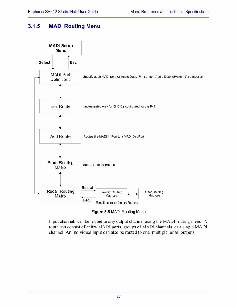
3.1.5 MADI Routing Menu
Figure 3-6 MADI Routing Menu
Input channels can be routed to any output channel using the MADI routing menu. A route can consist of entire MADI ports, groups of MADI channels, or a single MADI channel. An individual input can also be routed to one, multiple, or all outputs.
MADI SetupMenu
Select Esc
MADI PortDefinitions
Specify each MADI port for Audio Deck (R-1) or non-Audio Deck (System 5) connection
Implemented only for SH612s configured for the R-1
Add Route
Store RoutingMatrix
Recall RoutingMatrix
Select
Esc
Factory RoutingMatrices
User RoutingMatrices
Edit Route
Routes the MADI In Port to a MADI Out Port
Stores up to 20 Routes
Recalls user or factory Routes
27
Euphonix SH612 Studio Hub User Guide Menu Reference and Technical Specifications
To create a route:
1. Press the MADI port button corresponding to the port to route to or from.
The Add Route submenu appears displaying the input and output ports and channels. You can also locate to the Add Route Menu through the menu system.
In: [1: 1 - 56] To Out: [1: 1- 56]
2. Use the arrow keys to move the cursor under the number to adjust and the SpinKnob to adjust the number.
3. Press Select to finalize the route.
NOTE: The SH612 does not provide visual confirmation of the active routes so you must check that the route was correct by looking at the meters on the R-1 or System 5 console.
MADI Port Definitions
This parameter can specify each MADI port for AudioDeck (R-1) or non-AudioDeck (System 5) connections. For the R-1 version 3, the MADI port definitions (AudioDeck vs. non-AudioDeck) are saved as part of a user routing preset and are not Global settings. If you change your port definitions, you need to update existing user presets with the new settings.
Edit Route
Modifies the mapping of MADI input ports to output ports.
Add Route
Press Select to display:
In: [1: 1 - 56] To Out: [1: 1- 56]
Use the arrow keys to move between the In/Out port numbers and the SpinKnob to set the port number.
NOTE: Edit Route, Add Route, Recall Routing Matrix, and Store Routing Matrix are available only for SH612s configured for the R-1. These options are not available for SH612s configured for System 5.
Store Routing Matrix
Stores up to 20 frequently used custom routes for instant recall.
28
Euphonix SH612 Studio Hub User Guide Menu Reference and Technical Specifications
Recall Routing Matrix
Recalls stored routes. The R-1 default route for sample rates in the range 3250 kHz is 24 / 144 Track R-1 [56]; for sample rates over 50 kHz, R-1 24 / 48 / 96 Track [28].
Factory Routing Matrices Menu
R-1 Through [56]
Through [56]
24144 Track R-1 [56]
3 x 48-Track Splitter/Merger [56]
S-5 R-1.0
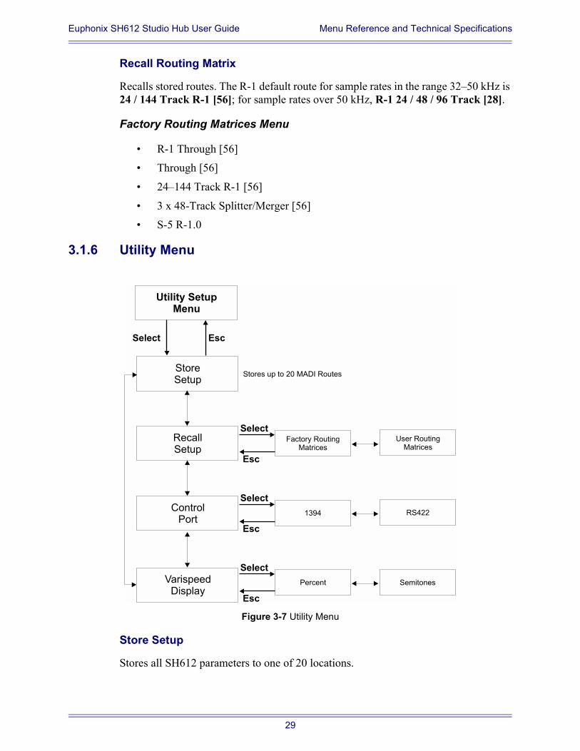
3.1.6 Utility Menu
Figure 3-7 Utility Menu
Store Setup
Stores all SH612 parameters to one of 20 locations.
Utility SetupMenu
Select Esc
StoreSetup
RecallSetup
ControlPort
Select
Esc
Factory RoutingMatrices
User RoutingMatrices
Stores up to 20 MADI Routes
VarispeedDisplay
Select
Esc
1394 RS422
Select
Esc
Percent Semitones
29
Euphonix SH612 Studio Hub User Guide Menu Reference and Technical Specifications
Recall SetupRecalls all parameters from one of 20 locations.
Control Port
This must be set correctly to control the SH612 from the R-1 recorder or System 5 con-sole. The SH612 can be controlled from System 5 from the RS422 Control port (serial 9-pin connector) or from the R-1 from the IEEE-1394 port. The unit may appear to be disabled if the control port selected here does not match the connected port.
Varispeed Display
Shows the extent to which playback speed is altered.
Percent: -12.5% to + 12.5%
Semitones: -2.32 to + 2.40 semitones
3.1.7 Transport
Used with the R-1, the Transport menu converts the SH612 front panel menu controls into Transport controls. This allows the SH612 to send Machine Control commands to other devices. This feature is not implemented for use with System 5.
The R-1 must be set to receive Machine Control commands from the SH612 and Ma-chine Control must be turned on. Two menus provide different controls.
The first menu has:
Stop: Menu marked by a square; controlled by the Info button
Forward Play: Menu marked by a single right arrow; controlled by the button with a single, right arrow
Reverse Play: Menu marked by a single left arrow; controlled by the button with a single, left arrow
The second menu has:
Stop: Menu marked by a square; controlled by the Info button
Forward Shuttle: Menu marked by a double, right arrow; controlled by the button with a single, right arrow
Reverse Shuttle: Menu marked by a double, left arrow; controlled by the but-ton with a single, left arrow
In the top of each menu the time and play/ stop /shuttle status is shown.
30
Euphonix SH612 Studio Hub User Guide Menu Reference and Technical Specifications
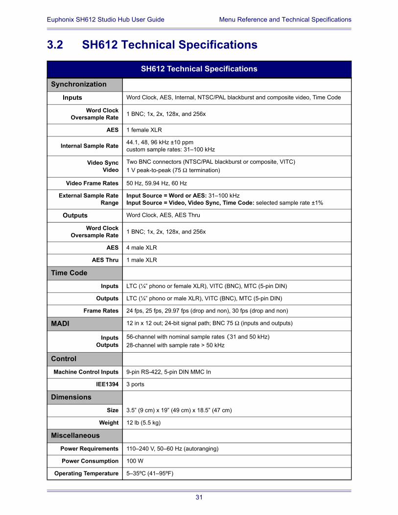
3.2 SH612 Technical Specifications
SH612 Technical Specifications
Synchronization
Inputs Word Clock, AES, Internal, NTSC/PAL blackburst and composite video, Time Code
Word ClockOversample Rate 1 BNC; 1x, 2x, 128x, and 256x
AES 1 female XLR
Internal Sample Rate 44.1, 48, 96 kHz ±10 ppmcustom sample rates: 31100 kHz
Video SyncVideo
Two BNC connectors (NTSC/PAL blackburst or composite, VITC)1 V peak-to-peak (75 Ω termination)
Video Frame Rates 50 Hz, 59.94 Hz, 60 Hz
External Sample RateRange
Input Source = Word or AES: 31100 kHzInput Source = Video, Video Sync, Time Code: selected sample rate ±1%
Outputs Word Clock, AES, AES Thru
Word ClockOversample Rate 1 BNC; 1x, 2x, 128x, and 256x
AES 4 male XLR
AES Thru 1 male XLR
Time Code
Inputs LTC (¼ phono or female XLR), VITC (BNC), MTC (5-pin DIN)
Outputs LTC (¼ phono or male XLR), VITC (BNC), MTC (5-pin DIN)
Frame Rates 24 fps, 25 fps, 29.97 fps (drop and non), 30 fps (drop and non)
MADI 12 in x 12 out; 24-bit signal path; BNC 75 Ω (inputs and outputs)
InputsOutputs
56-channel with nominal sample rates (31 and 50 kHz)28-channel with sample rate > 50 kHz
Control
Machine Control Inputs 9-pin RS-422, 5-pin DIN MMC In
IEE1394 3 ports
Dimensions
Size 3.5 (9 cm) x 19 (49 cm) x 18.5 (47 cm)
Weight 12 lb (5.5 kg)
Miscellaneous
Power Requirements 110240 V, 5060 Hz (autoranging)
Power Consumption 100 W
Operating Temperature 535ºC (4195ºF)
31