Embed Size (px)
Citation preview
INST
RU
CTI
ON
S M
AN
UA
L PPRROOCCEESSSSIINNGG WWAATTEERR CCHHIILLLLEERR
GGCC LLTT
RREEVVIISSIIOONN 33 DDAATTEE 1155//1100//22000044
VVEERRSSIIOONN 11
EUROCHILLER S.r.l. INTERNATIONAL COOLING Via Milano, 69 27030 CASTELLO D’AGOGNA (PV) ITALIATEL. 0384-298985 - FAX 0384-298984 SERVICE 0384-298981 e-mail [email protected]
Processing water chiller Model GC
Instruction, use and maintenance manual – ©02_10/02 Page 2
HOW TO READ AND USE THIS OPERATING HANDBOOK This handbook is supplied in one copy when buying the machine. In case the customer requires more copies, he must order them to the Builder, stating the model and the machine serial number (the data are printed on the machine identification plate) The user of this machine must be a professionally skilled operator with a good experience on similar machines. On the contrary, the user must attend a training course for the machine use at the Builder's or reseller's or a training course held by the Builder's qualified personnel. This handbook must be regarded as an integrating part of the machine and therefore it must be always available for reading and must be kept in a dry and safe place far from sunbeams. The builder authorises the User to produce some copies of this document for internal use only. With the term ATTENTION is used to identify any actions which could compromise the machine condition and which could cause a danger, risk for the operator. These warnings are printed in Italics and sometimes in bold script.
Attention:
The machine manufacturer, EUROCHILLER S.r.l. reserves the right to change the measurements, shape and characteristics of the machine at any time without prior notice.
Model GC Processing water chiller
Page 3 Instruction, use and maintenance manual – ©02_10/02
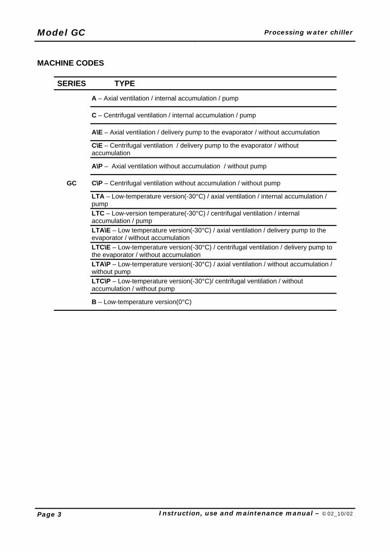
MACHINE CODES
SERIES TYPE
A – Axial ventilation / internal accumulation / pump
C – Centrifugal ventilation / internal accumulation / pump
A\E – Axial ventilation / delivery pump to the evaporator / without accumulation
C\E – Centrifugal ventilation / delivery pump to the evaporator / without accumulation
A\P – Axial ventilation without accumulation / without pump
GC C\P – Centrifugal ventilation without accumulation / without pump
LTA – Low-temperature version(-30°C) / axial ventilation / internal accumulation / pump
LTC – Low-version temperature(-30°C) / centrifugal ventilation / internal accumulation / pump
LTA\E – Low temperature version(-30°C) / axial ventilation / delivery pump to the evaporator / without accumulation
LTC\E – Low-temperature version(-30°C) / centrifugal ventilation / delivery pump to the evaporator / without accumulation
LTA\P – Low-temperature version(-30°C) / axial ventilation / without accumulation / without pump
LTC\P – Low-temperature version(-30°C)/ centrifugal ventilation / without accumulation / without pump
B – Low-temperature version(0°C)
Processing water chiller Model GC
Instruction, use and maintenance manual – ©02_10/02 Page 4
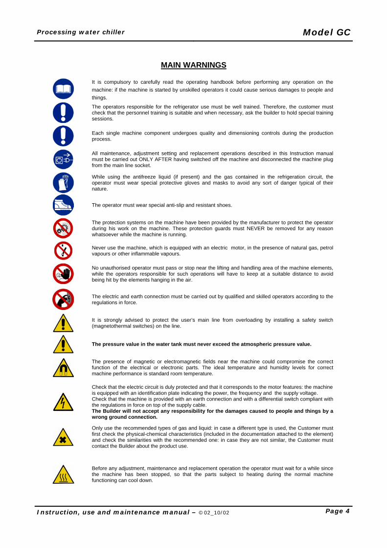
MAIN WARNINGS
It is compulsory to carefully read the operating handbook before performing any operation on the machine: if the machine is started by unskilled operators it could cause serious damages to people and things.
The operators responsible for the refrigerator use must be well trained. Therefore, the customer must check that the personnel training is suitable and when necessary, ask the builder to hold special training sessions.
Each single machine component undergoes quality and dimensioning controls during the production process.
All maintenance, adjustment setting and replacement operations described in this Instruction manual must be carried out ONLY AFTER having switched off the machine and disconnected the machine plug from the main line socket.
While using the antifreeze liquid (if present) and the gas contained in the refrigeration circuit, the operator must wear special protective gloves and masks to avoid any sort of danger typical of their nature.
The operator must wear special anti-slip and resistant shoes.
The protection systems on the machine have been provided by the manufacturer to protect the operator during his work on the machine. These protection guards must NEVER be removed for any reason whatsoever while the machine is running.
Never use the machine, which is equipped with an electric motor, in the presence of natural gas, petrol vapours or other inflammable vapours.
No unauthorised operator must pass or stop near the lifting and handling area of the machine elements, while the operators responsible for such operations will have to keep at a suitable distance to avoid being hit by the elements hanging in the air.
The electric and earth connection must be carried out by qualified and skilled operators according to the regulations in force.
It is strongly advised to protect the user’s main line from overloading by installing a safety switch (magnetothermal switches) on the line.
The pressure value in the water tank must never exceed the atmospheric pressure value.
The presence of magnetic or electromagnetic fields near the machine could compromise the correct function of the electrical or electronic parts. The ideal temperature and humidity levels for correct machine performance is standard room temperature.
Check that the electric circuit is duly protected and that it corresponds to the motor features: the machine is equipped with an identification plate indicating the power, the frequency and the supply voltage. Check that the machine is provided with an earth connection and with a differential switch compliant with the regulations in force on top of the supply cable. The Builder will not accept any responsibility for the damages caused to people and things by a wrong ground connection.
Only use the recommended types of gas and liquid: in case a different type is used, the Customer must first check the physical-chemical characteristics (included in the documentation attached to the element) and check the similarities with the recommended one: in case they are not similar, the Customer must contact the Builder about the product use.
Before any adjustment, maintenance and replacement operation the operator must wait for a while since the machine has been stopped, so that the parts subject to heating during the normal machine functioning can cool down.
Model GC Processing water chiller
Page 5 Instruction, use and maintenance manual – ©02_10/02
INSTRUCTION MANUAL CONTENTS
CHAPTER 1- GENERAL INFORMATION CONCERNING THE INSTRUCTION MANUAL 7
1.1 Introduction ............................................................................................................................. 7 1.2 Reference to standards........................................................................................................... 7 1.3 Aim of this document............................................................................................................... 7 1.4 Machine marking data and identification plate........................................................................ 7 1.5 Use and conserving of this manual ......................................................................................... 7 1.6 Respecting current legislation................................................................................................. 8 1.7 Information for the machine user ............................................................................................ 8
CHAPTER 2- PROTECTION SYSTEMS PROVIDED FOR THE OPERATOR’S SAFETY.. 9 2.1 Protection systems on the machine ........................................................................................ 9 2.2 Identification plate ................................................................................................................... 9
CHAPTER 3- EVENTUAL ADDITIONAL DANGER RISKS............................................... 10 3.1 Information concerning safety conditions and additional risks.............................................. 10
CHAPTER 4- CORRECT AND INCORRECT MACHINE USE........................................... 12 4.1 Warning advice against danger as a result of incorrect use ................................................. 12
CHAPTER 5- GENERAL DESCRIPTION OF THE MACHINE........................................... 13 5.1 Tables for the calculation of the refrigerating yield................................................................ 14 5.1.1 “GC LT”Tables for the calculation of the refrigerating yield................................................ 15 5.2 Operating principle................................................................................................................ 17 5.2.1 Cooling circuit .................................................................................................................... 17 5.2.2 Cooling circuit with hot gas (OPTIONAL)........................................................................... 17 5.2.3 Hydraulic circuit.................................................................................................................. 19
CHAPTER 6- MOVING AND TRANSPORTING THE MACHINE....................................... 21 6.1 Transporting the machine ..................................................................................................... 21 6.2 Weights ................................................................................................................................. 21
CHAPTER 7- MACHINE INSTALLATION ......................................................................... 22 7.1 Max machine size ................................................................................................................. 22 7.2 Area to be left free around the machine................................................................................ 23 7.3 Positioning for air canalization .............................................................................................. 24
CHAPTER 8- ASSEMBLAGE AND PREPARATION OF THE MACHINE TO WORK ...... 26 8.1 Preliminary control checks .................................................................................................... 26 8.2 Control check on any damage the machine may have suffered during transport ................. 26 8.3 Power supply connection ...................................................................................................... 27 8.3.1 Power supply connection ................................................................................................... 28 8.4 Hydraulic connection............................................................................................................. 32 8.4.1 Water pipes connection ..................................................................................................... 33 8.4.2 In-out connection sizes ...................................................................................................... 34 8.4.3 Hydraulic attacks position gc-lt........................................................................................... 35 8.5 Use of antifreeze in the process water.................................................................................. 36 8.5.1 % Glycol Yield diagram – Evaporator power..................................................................... 36 8.5.2 Ratio between the cooling and concentration points of water solutions in glycol............... 37 8.5.3 Antifreeze liquid filling system FILL-CHILL (Optional, for version GC 9 to GC 55 only) .... 37 8.5.4 Water content in the tank ................................................................................................... 38 8.5.5 Water pipes capacity.......................................................................................................... 38
Processing water chiller Model GC
Instruction, use and maintenance manual – ©02_10/02 Page 6
CHAPTER 9- CONTROL PANEL ...................................................................................... 39 9.1 Control panel for models GC 2 to GC 6 ................................................................................ 39 9.2 Display and functions............................................................................................................ 39 9.2.1 Set point programming....................................................................................................... 40 9.3 Control panel for models GC 9 to GC 55 .............................................................................. 40 9.4 Display and functions............................................................................................................ 41 9.4.1 Modifyng the temperature setting....................................................................................... 41 9.4.2 Resetting the alarm............................................................................................................ 42 9.4.3 Modifyng the configuration parameters.............................................................................. 42
CHAPTER 10- MACHINE USE .......................................................................................... 43 10.1 Start-up and work cycle(for models GC 9 to GC 55 version excluded GC-E)..................... 43 10.2 Unforeseen stopping due to a power cut ............................................................................ 44 10.3 Stopping the machine manually .......................................................................................... 44 10.4 Reset thermomagnetic protection (for version GC 9 to GC 55 only)................................... 44
CHAPTER 11- MACHINE MAINTENANCE ....................................................................... 45 11.1 Programmed maintenance.................................................................................................. 45 11.2 Maintenance operations for axial fans (VER. GC-A)........................................................... 46 11.3 Cleaning the filters panel..................................................................................................... 46 11.4 Reset of the gas high pressure gauge .........................Errore. Il segnalibro non è definito. 11.4.1 Reset of the gas high pressure gauge (for version GC 2 to GC 6 only).................Errore. Il segnalibro non è definito. 11.4.2 Reset of the gas high pressure gauge (for version GC 9 to GC 55 only)......................... 47 11.5 Maintenance ON-OFF level switches.................................................................................. 48 11.6 Maintenance pumps............................................................................................................ 48 11.7 Maintenance an regulating differential by-pass valve (for versions GC 9 to GC 55 only)... 48 11.8 Amount of coolant. Type of oil. .......................................................................................... 48 11.9 Cleaning the control instruments (perform with machine switched off)............................... 48
CHAPTER 12- MODIFYNG THE PROTECTED PARAMETER (FOR VERSIONS GC 9 TO GC 55 ONLY) ..................................................................................................................... 49
12.1 gc lt Programme parameters............................................................................................... 50 12.2 IN / OUT list ........................................................................................................................ 51 12.3 Parameters programming (for versions GC 2 to GC 6)....................................................... 52 12.4 Programmable parameters ................................................................................................. 53 12.4.1 Parameters table.............................................................................................................. 53 12.5 Parameters description ....................................................................................................... 54 12.6 Errors signalling .................................................................................................................. 55 12.7 Cleaning.............................................................................................................................. 55
CHAPTER 13- TROUBLESHOOTING............................................................................... 56 13.1 LED H1 / H2 – (par 9.3) ...................................................................................................... 56 13.2 LED H3 ............................................................................................................................... 57 13.3 LED H4 ............................................................................................................................... 58 13.4 LED H5 / H7 / H10 .............................................................................................................. 59 13.5 LED H8 / H9........................................................................................................................ 60
CHAPTER 14- LIST OF COMPONENTS........................................................................... 61 CHAPTER 15- SPARE PARTS REQUESTS ..................................................................... 69 CHAPTER 16- MACHINE DEMOLITION ........................................................................... 75
Model GC Processing water chiller
Page 7 Instruction, use and maintenance manual – ©02_10/02
CHAPTER 1- GENERAL INFORMATION CONCERNING THE
INSTRUCTION MANUAL 1.1 INTRODUCTION This manual is very important for learning to know and operate the machine correctly. It is essential that the manual be read carefully before using the machine. Each machine is sold together with its own instruction manual. The machine user is responsible for keeping the manual for reference during the total machine life, making sure that the manual is not lost or destroyed until the machine has been demolished. The EUROCHILLER S.r.l. will not be held responsible for any tampering with this manual or for any changes made on the machine after its delivery, which have not been included and described in this manual. This causes the termination of the warranty The manufacturer reserves all technical and intellectual rights to the contents of this manual and all reproduction is prohibited, whether total or partial, and in any form whatsoever (printing, photocopying, microfilm, or other means). Reproduction is also forbidden using electronic systems, or transmission to third parties without the approval and registration by the manufacturer. 1.2 REFERENCE TO STANDARDS The indications contained in the following documents have been used in this handbook: - Directive 98/37/EEC dated 22/06/1998 (that replaces the directive 89/392/EEC implemented in Italy by the Presidential Decree
459/96) - Directive 73/23/EEC dated 19/02/1973. - Directive 92/31/EEC of 28/04/1992, implementing the Directive 89/336/EEC. - Directive 97/23/EC on the use of pressure equipment (PED) – (of the 01/06/02) - UNI EN 292 -1 Nov. 92 - Machine safety: Terminology - UNI EN 292 - 2 Nov. 92 - Machine safety: Specifications and technical principles - CEI EN 60204-1 Apr. 98 - Machine safety: Machine electric equipment 1.3 AIM OF THIS DOCUMENT The aim of this document is to provide the user with all information and instructions necessary for correct machine use and for the protection of the operator from all danger while working on the machine. All instructions must be obeyed carefully. For this reason the user is bound to the following: - keep this document handy and accessible to the work area, making it available to the operator. The machine operator must read
the manual before using the machine. - the manual must be transferred to the following owner if the machine is sold or transferred. 1.4 MACHINE MARKING DATA AND IDENTIFICATION PLATE The Builder data, the machine model and serial number are indicated on the machine plate. Always refer to the data indicated on this plate for any communication about the machine (troubles, servicing during the warranty period, spare parts, etc.). The plate also shows the EC marking assuring the machine compliance with EEC regulations in force. All the warning notices present on the machine must be strictly observed and never removed. 1.5 USE AND CONSERVING OF THIS MANUAL This manual has been written for the machine user, the personnel responsible for handling and transport, the operator, the control and maintenance personnel, and those responsible for its final demolition. The manual was drawn up to provide all necessary information concerning the machine design, technical features, instructions for handling, adequate and safe installation, assembly, setting and use; it provides information on maintenance, ordering spare parts, and on any possible danger risks on the machine. In particular, the manual must be readily available for the following : - conditions necessary for machine installation - operator’s work position - instructions concerning:
• set up, • use, • transport, • installation, • assembly and disassembly, • setting interventions, • maintenance and repairs, • any necessary training instructions.
Processing water chiller Model GC
Instruction, use and maintenance manual – ©02_10/02 Page 8
1.6 RESPECTING CURRENT LEGISLATION As well as the rules and instructions contained in this manual, the user must apply all current legislation and standards concerning safety in work environments to prevent injury to personnel. 1.7 INFORMATION FOR THE MACHINE USER 1 - The manufacturer reserves the right to update any successive production and manuals without the necessity to update previous
machines and manuals. 2 - Materials may be changed at any time according to technical evolution without prior notice. 3 - In any cases where the electrical protection controls are removed from the installation ( the electrical panel on the machine) the
Manufacturer will not assume any responsibility for problems concerning safety measures as a result of electrical parts which do not comply with current standards and regulations. In any case, all responsibility for ensuring that the appropriate standards and legislation for electrical equipment attached to the machine lies with the customer, who must control that this work has been carried out correctly to standard.
4 - The manufacturer will not be held responsible for damage caused by any of the following: incorrect machine use use by untrained personnel use not in compliance with current standards use with faulty main line supplies lack of maintenance and repairs as advised in this manual non-authorised changes and /or modifications. Changes must receive the manufacturer’s written permission use with non original spare parts, or parts not designed for the machine use with the partial or complete disregard for the instructions contained in this manual
5 - The general sales guarantee is not considered as valid in the following cases: • incorrect machine use • Tampering with the machine • bad machine conservation • problems arising from incorrect machine use • use by untrained personnel • exceeding the machine’s performance limits • excessive use of all mechanical, electrical and/or pneumatic parts • machine use in unsuitable or dangerous conditions as described in point 4.
Any requests for extra copies of this manual must be made from the manufacturer demonstrating the proof of purchase. Copies are obtainable from EUROCHILLER S.r.l.
Model GC Processing water chiller
Page 9 Instruction, use and maintenance manual – ©02_10/02
CHAPTER 2- PROTECTION SYSTEMS PROVIDED FOR THE
OPERATOR’S SAFETY 2.1 PROTECTION SYSTEMS ON THE MACHINE The manufacturer has provided mechanical protection systems on the machine to protect the operator from any contact, even accidental, with any of the machine parts which can cause danger:
1. The perimeter has been marked by safety panels made of sheet, fixed by clamping screws, wrench required for opening.
An IP54 door protecting the electric board is assembled on the front part: it is closed by the main switch and a series of hexagonal screws that can be opened only with a wrench;
The rear side is equipped with a filter made of synthetic material; it is used to filter the capacitor operating air.
2. The fan, positioned on the refrigerator upper side, is equipped with a fixed protection grid IP 2X for the fingers covering it completely.
3. All the elements subject to heating during the normal production cycle have been covered with insulating material, so that the outer surface cannot overheat.
Attention:
The protection systems on the machine have been provided by the manufacturer to protect the operator during his work on the machine. These protection guards must NEVER be removed for any reason whatsoever while the machine is running.
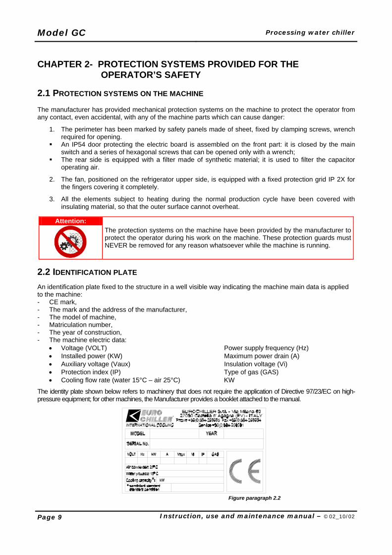
2.2 IDENTIFICATION PLATE An identification plate fixed to the structure in a well visible way indicating the machine main data is applied to the machine: - CE mark, - The mark and the address of the manufacturer, - The model of machine, - Matriculation number, - The year of construction, - The machine electric data:
• Voltage (VOLT) Power supply frequency (Hz) • Installed power (KW) Maximum power drain (A) • Auxiliary voltage (Vaux) Insulation voltage (Vi) • Protection index (IP) Type of gas (GAS) • Cooling flow rate (water 15°C – air 25°C) KW
The identity plate shown below refers to machinery that does not require the application of Directive 97/23/EC on high-pressure equipment; for other machines, the Manufacturer provides a booklet attached to the manual.
Figure paragraph 2.2
Processing water chiller Model GC
Instruction, use and maintenance manual – ©02_10/02 Page 10
CHAPTER 3- EVENTUAL ADDITIONAL DANGER RISKS
3.1 INFORMATION CONCERNING SAFETY CONDITIONS AND ADDITIONAL RISKS This equipment has been conceived by reducing all the sources and situations of danger to the minimum. Danger conditions can occur only if the installation rules are not observed or because of a wrong use of the product. DANGER DERIVING FROM CONTACT BETWEEN PRODUCTS AND OBJECTS OR PERSONS The movement of the fan poses a danger. The protection grill has a utility pitch of less than 12 mm IP 2X between wires. A further hazard is posed by accidental contact with the capacitor whose aluminium winglets can cause cuts. The capacitor is protected by filtering panels, which guarantee adequate safety levels under normal conditions. The utmost care must be taken when removing or repositioning the filter. SSAAFFEETTYY RREEGGUULLAATTIIOONNSS FFOORR EELLEECCTTRRIICCAALL EEQQUUIIPPMMEENNTTSS The causes of electrical risks are well known and prevention is not difficult if attention is constant. To reduce the number of incidents of an electrical origin, personnel must be informed of potential danger and instructed on safety procedures. MANAGERS RESPONSABILITIES Managers must be informed of potential risks of the system and keep electrical equipment personnel under control. Control consists in locating possible risk conditions and investigating problems found by personnel during maintenance operations. Any defective components must be repaired or replaced immediately. The manager must make sure that safety measures are observed without tolerating or accepting deviations, in as much as damage to persons or apparatus may occur. HIGH VOLTAGE Contact with high voltage circuits can provoke burns, shock, unconsciousness or death by electrocution. This may be caused by a scarce knowledge of dangers connected to use of electric apparatus. SAFETY REGULATIONS WHILE CARRYING OUT MAINTENENCE WITH MACHINE ON - personnel must not carry out operations alone; - whenever possible operations must be carried out using only one hand; - check instruments and conducting wires periodically; - check that personnel is fully aware of the apparatus components and maintenance procedures before
carrying out any work; - use protective gloves; - open all apparatus power supply contacts before taking resistance values; - check that in the low voltage circuit high voltage is not present; - do not use magnetic utensils near strong magnetic fields.. - If there’s a dangerous situation. NNOOXXIIOOUUSS SSUUBBSSTTAANNCCEESS (XN) This unit contains and uses R22/R407c/R404a gas up to a maximum of 17 kg; the circuit is completely sealed. If a sudden leakage of refrigerant occurs, operators must move out of the vicinity and the room must be ventilated and don’t use free flames.
Model GC Processing water chiller
Page 11 Instruction, use and maintenance manual – ©02_10/02
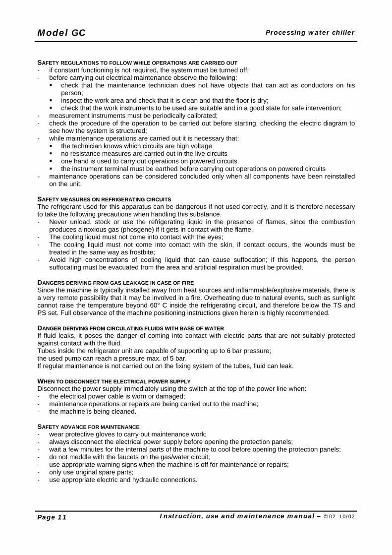
SAFETY REGULATIONS TO FOLLOW WHILE OPERATIONS ARE CARRIED OUT - if constant functioning is not required, the system must be turned off; - before carrying out electrical maintenance observe the following:
check that the maintenance technician does not have objects that can act as conductors on his person;
inspect the work area and check that it is clean and that the floor is dry; check that the work instruments to be used are suitable and in a good state for safe intervention;
- measurement instruments must be periodically calibrated; - check the procedure of the operation to be carried out before starting, checking the electric diagram to
see how the system is structured; - while maintenance operations are carried out it is necessary that:
the technician knows which circuits are high voltage no resistance measures are carried out in the live circuits one hand is used to carry out operations on powered circuits the instrument terminal must be earthed before carrying out operations on powered circuits
- maintenance operations can be considered concluded only when all components have been reinstalled on the unit.
SSAAFFEETTYY MMEEAASSUURREESS OONN RREEFFRRIIGGEERRAATTIINNGG CCIIRRCCUUIITTSS The refrigerant used for this apparatus can be dangerous if not used correctly, and it is therefore necessary to take the following precautions when handling this substance. - Never unload, stock or use the refrigerating liquid in the presence of flames, since the combustion
produces a noxious gas (phosgene) if it gets in contact with the flame. - The cooling liquid must not come into contact with the eyes; - The cooling liquid must not come into contact with the skin, if contact occurs, the wounds must be
treated in the same way as frostbite; - Avoid high concentrations of cooling liquid that can cause suffocation; if this happens, the person
suffocating must be evacuated from the area and artificial respiration must be provided. DANGERS DERIVING FROM GAS LEAKAGE IN CASE OF FIRE Since the machine is typically installed away from heat sources and inflammable/explosive materials, there is a very remote possibility that it may be involved in a fire. Overheating due to natural events, such as sunlight cannot raise the temperature beyond 60° C inside the refrigerating circuit, and therefore below the TS and PS set. Full observance of the machine positioning instructions given herein is highly recommended. DAANNGGEERR DDEERRIIVVIINNGG FFRROOMM CCIIRRCCUULLAATTIINNGG FFLLUUIIDDSS WWIITTHH BBAASSEE OOFF WWAATTEERR If fluid leaks, it poses the danger of coming into contact with electric parts that are not suitably protected against contact with the fluid. Tubes inside the refrigerator unit are capable of supporting up to 6 bar pressure; the used pump can reach a pressure max. of 5 bar. If regular maintenance is not carried out on the fixing system of the tubes, fluid can leak. WWHHEENN TTOO DDIISSCCOONNNNEECCTT TTHHEE EELLEECCTTRRIICCAALL PPOOWWEERR SSUUPPPPLLYY Disconnect the power supply immediately using the switch at the top of the power line when: - the electrical power cable is worn or damaged; - maintenance operations or repairs are being carried out to the machine; - the machine is being cleaned. SAFETY ADVANCE FOR MAINTENANCE - wear protective gloves to carry out maintenance work; - always disconnect the electrical power supply before opening the protection panels; - wait a few minutes for the internal parts of the machine to cool before opening the protection panels; - do not meddle with the faucets on the gas/water circuit; - use appropriate warning signs when the machine is off for maintenance or repairs; - only use original spare parts; - use appropriate electric and hydraulic connections.
Processing water chiller Model GC
Instruction, use and maintenance manual – ©02_10/02 Page 12
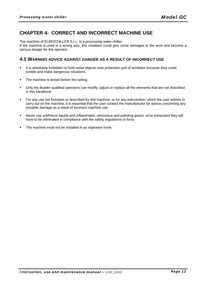
CHAPTER 4- CORRECT AND INCORRECT MACHINE USE The machine of EUROCHILLER S.r.l., is a processing water chiller. If the machine is used in a wrong way, this condition could give some damages to the work and become a serious danger for the operator. 4.1 WARNING ADVICE AGAINST DANGER AS A RESULT OF INCORRECT USE It is absolutely forbidden to hold metal objects near protection grid of ventilator because they could
tumble and make dangerous situations. The machine is tested before the selling.
Only the Builder qualified operators can modify, adjust or replace all the elements that are not described
in this handbook. For any use not foreseen or described for this machine, or for any intervention, which the user wishes to
carry out on the machine, it is essential that the user contact the manufacturer for advice concerning any possible damage as a result of incorrect machine use.
Never use antifreeze liquids and inflammable, obnoxious and polluting gases: once exhausted they will
have to be eliminated in compliance with the safety regulations in force. The machine must not be installed in an explosive room.
Model GC Processing water chiller
Page 13 Instruction, use and maintenance manual – ©02_10/02
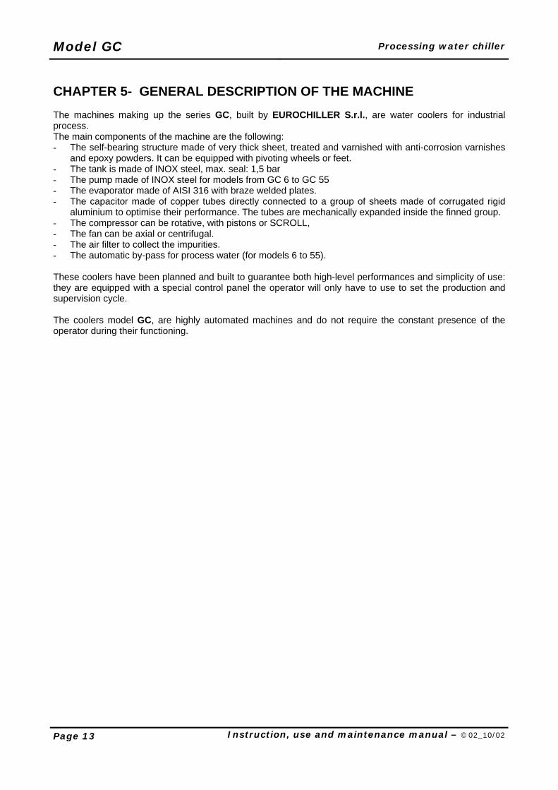
CHAPTER 5- GENERAL DESCRIPTION OF THE MACHINE The machines making up the series GC, built by EUROCHILLER S.r.l., are water coolers for industrial process. The main components of the machine are the following: - The self-bearing structure made of very thick sheet, treated and varnished with anti-corrosion varnishes
and epoxy powders. It can be equipped with pivoting wheels or feet. - The tank is made of INOX steel, max. seal: 1,5 bar - The pump made of INOX steel for models from GC 6 to GC 55 - The evaporator made of AISI 316 with braze welded plates. - The capacitor made of copper tubes directly connected to a group of sheets made of corrugated rigid
aluminium to optimise their performance. The tubes are mechanically expanded inside the finned group. - The compressor can be rotative, with pistons or SCROLL, - The fan can be axial or centrifugal. - The air filter to collect the impurities. - The automatic by-pass for process water (for models 6 to 55). These coolers have been planned and built to guarantee both high-level performances and simplicity of use: they are equipped with a special control panel the operator will only have to use to set the production and supervision cycle. The coolers model GC, are highly automated machines and do not require the constant presence of the operator during their functioning.
Processing water chiller Model GC
Instruction, use and maintenance manual – ©02_10/02 Page 14
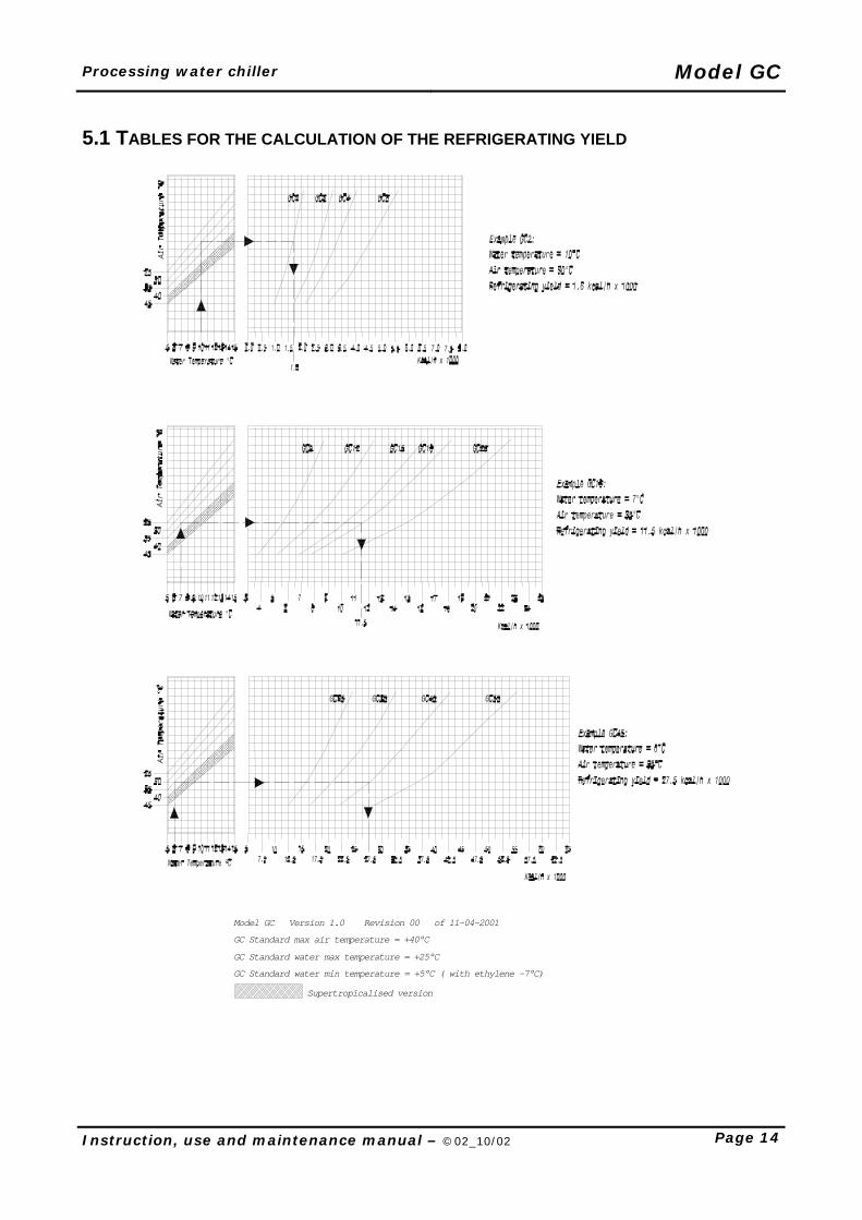
5.1 TABLES FOR THE CALCULATION OF THE REFRIGERATING YIELD
GC Standard water min temperature = +5°C ( with ethylene -7°C)
GC Standard water max temperature = +25°C
Model GC Version 1.0 Revision 00 of 11-04-2001
GC Standard max air temperature = +40°C
Supertropicalised version
Model GC Processing water chiller
Page 15 Instruction, use and maintenance manual – ©02_10/02
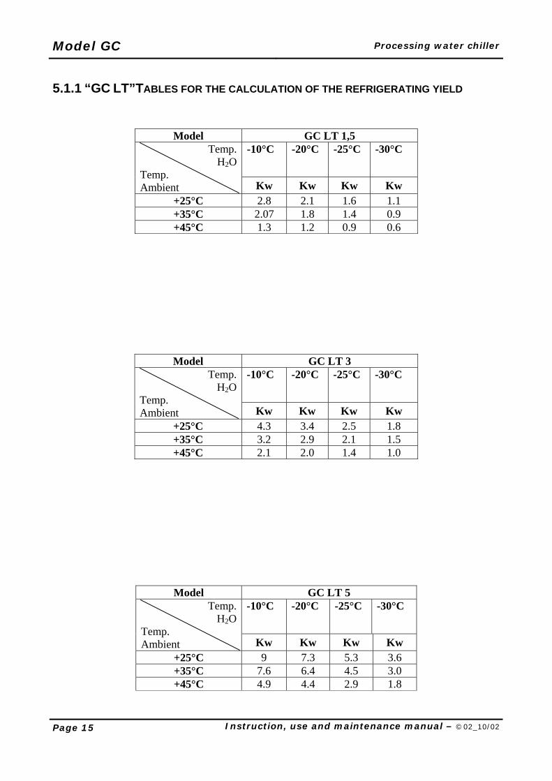
5.1.1 “GC LT”TABLES FOR THE CALCULATION OF THE REFRIGERATING YIELD
Model GC LT 1,5 -10°C -20°C -25°C -30°C Temp.
H2OTemp. Ambient Kw Kw Kw Kw
+25°C 2.8 2.1 1.6 1.1 +35°C 2.07 1.8 1.4 0.9 +45°C 1.3 1.2 0.9 0.6
Model GC LT 3 -10°C -20°C -25°C -30°C Temp.
H2OTemp. Ambient Kw Kw Kw Kw
+25°C 4.3 3.4 2.5 1.8 +35°C 3.2 2.9 2.1 1.5 +45°C 2.1 2.0 1.4 1.0
Model GC LT 5 -10°C -20°C -25°C -30°C Temp.
H2OTemp. Ambient Kw Kw Kw Kw
+25°C 9 7.3 5.3 3.6 +35°C 7.6 6.4 4.5 3.0 +45°C 4.9 4.4 2.9 1.8
Processing water chiller Model GC
Instruction, use and maintenance manual – ©02_10/02 Page 16
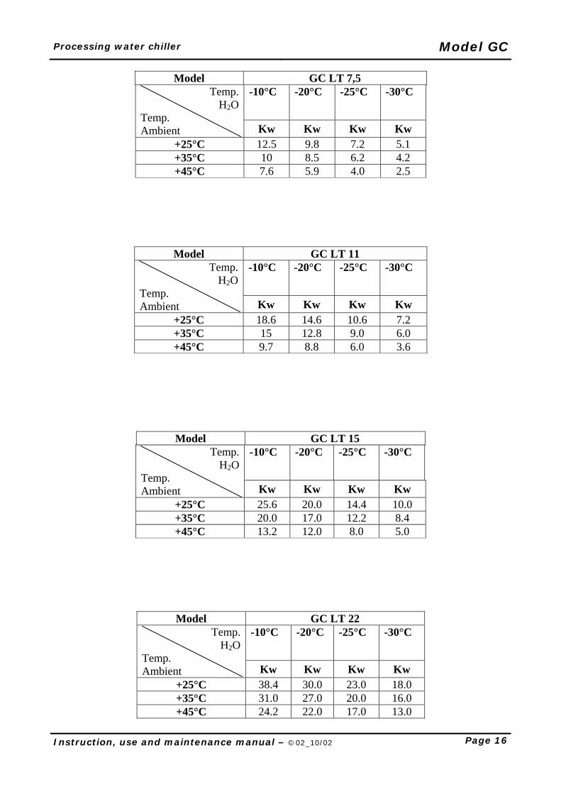
Model GC LT 7,5 -10°C -20°C -25°C -30°C Temp.
H2OTemp. Ambient Kw Kw Kw Kw
+25°C 12.5 9.8 7.2 5.1 +35°C 10 8.5 6.2 4.2 +45°C 7.6 5.9 4.0 2.5
Model GC LT 11 -10°C -20°C -25°C -30°C Temp.
H2OTemp. Ambient Kw Kw Kw Kw
+25°C 18.6 14.6 10.6 7.2 +35°C 15 12.8 9.0 6.0 +45°C 9.7 8.8 6.0 3.6
Model GC LT 15 -10°C -20°C -25°C -30°C Temp.
H2OTemp. Ambient Kw Kw Kw Kw
+25°C 25.6 20.0 14.4 10.0 +35°C 20.0 17.0 12.2 8.4 +45°C 13.2 12.0 8.0 5.0
Model GC LT 22 -10°C -20°C -25°C -30°C Temp.
H2OTemp. Ambient Kw Kw Kw Kw
+25°C 38.4 30.0 23.0 18.0 +35°C 31.0 27.0 20.0 16.0 +45°C 24.2 22.0 17.0 13.0
Model GC Processing water chiller
Page 17 Instruction, use and maintenance manual – ©02_10/02
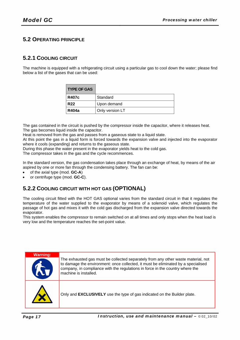
5.2 OPERATING PRINCIPLE 5.2.1 COOLING CIRCUIT The machine is equipped with a refrigerating circuit using a particular gas to cool down the water; please find below a list of the gases that can be used:
TYPE OF GAS
R407c Standard R22 Upon demand R404a Only version LT
The gas contained in the circuit is pushed by the compressor inside the capacitor, where it releases heat. The gas becomes liquid inside the capacitor. Heat is removed from the gas and passes from a gaseous state to a liquid state. At this point the gas in a liquid form is forced towards the expansion valve and injected into the evaporator where it cools (expanding) and returns to the gaseous state. During this phase the water present in the evaporator yields heat to the cold gas. The compressor takes in the gas and the cycle recommences.
In the standard version, the gas condensation takes place through an exchange of heat, by means of the air aspired by one or more fan through the condensing battery. The fan can be: • of the axial type (mod. GC-A) • or centrifuge type (mod. GC-C). 5.2.2 COOLING CIRCUIT WITH HOT GAS (OPTIONAL) The cooling circuit fitted with the HOT GAS optional varies from the standard circuit in that it regulates the temperature of the water supplied to the evaporator by means of a solenoid valve, which regulates the passage of hot gas and mixes it with the cold gas discharged from the expansion valve directed towards the evaporator. This system enables the compressor to remain switched on at all times and only stops when the heat load is very low and the temperature reaches the set-point value.
Warning:
The exhausted gas must be collected separately from any other waste material, not to damage the environment: once collected, it must be eliminated by a specialised company, in compliance with the regulations in force in the country where the machine is installed.
Only and EXCLUSIVELY use the type of gas indicated on the Builder plate.
Processing water chiller Model GC
Instruction, use and maintenance manual – ©02_10/02 Page 18
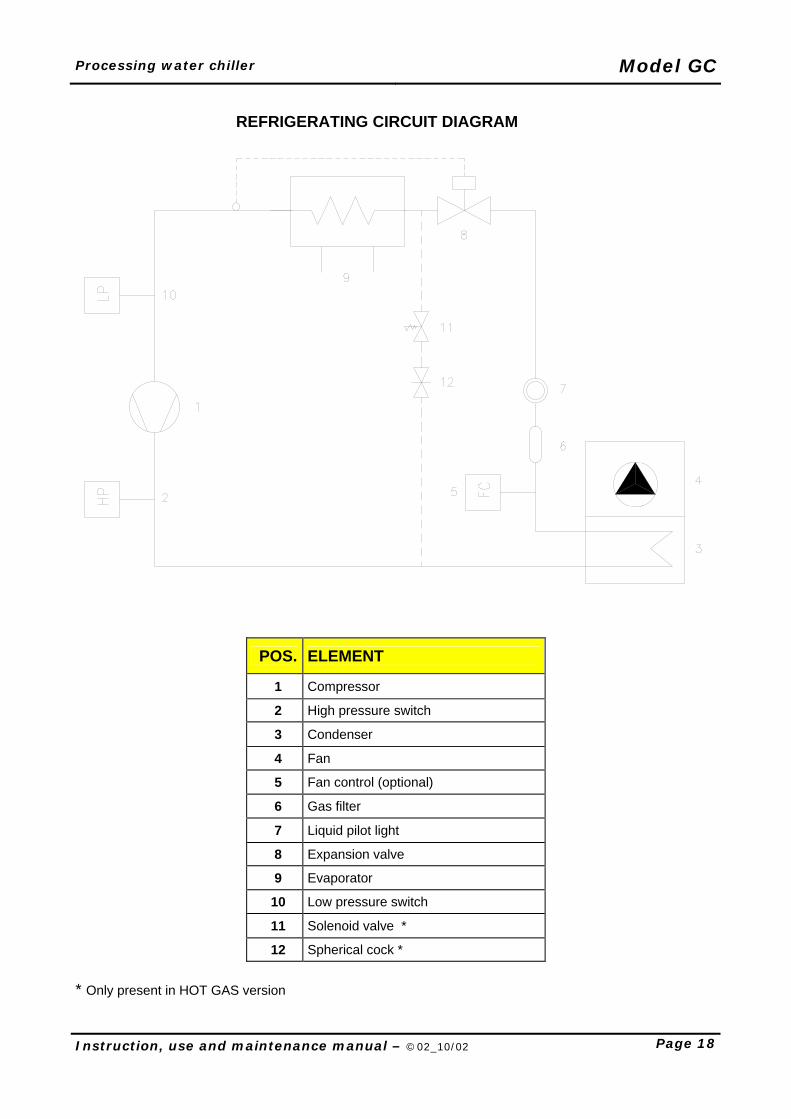
REFRIGERATING CIRCUIT DIAGRAM
POS. ELEMENT
1 Compressor
2 High pressure switch
3 Condenser
4 Fan
5 Fan control (optional)
6 Gas filter
7 Liquid pilot light
8 Expansion valve
9 Evaporator
10 Low pressure switch
11 Solenoid valve *
12 Spherical cock *
* Only present in HOT GAS version
Model GC Processing water chiller
Page 19 Instruction, use and maintenance manual – ©02_10/02
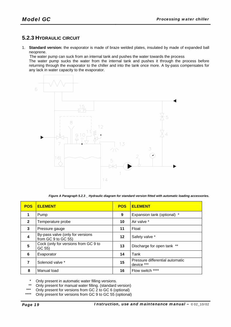
5.2.3 HYDRAULIC CIRCUIT 1. Standard version: the evaporator is made of braze welded plates, insulated by made of expanded ball
neoprene. The water pump can suck from an internal tank and pushes the water towards the process
The water pump sucks the water from the internal tank and pushes it through the process before returning through the evaporator to the chiller and into the tank once more. A by-pass compensates for any lack in water capacity to the evaporator.
Figure A Paragraph 5.2.3 _ Hydraulic diagram for standard version fitted with automatic loading accessories.
POS ELEMENT POS ELEMENT
1 Pump 9 Expansion tank (optional) *
2 Temperature probe 10 Air valve *
3 Pressure gauge 11 Float
4 By-pass valve (only for versions from GC 9 to GC 55) 12 Safety valve *
5 Cock (only for versions from GC 9 to GC 55) 13 Discharge for open tank **
6 Evaporator 14 Tank
7 Solenoid valve * 15 Pressure differential automatic device ***
8 Manual load 16 Flow switch **** * Only present in automatic water filling versions. ** Only present for manual water filling. (standard version) *** Only present for versions from GC 2 to GC 6 (optional) **** Only present for versions from GC 9 to GC 55 (optional)
Processing water chiller Model GC
Instruction, use and maintenance manual – ©02_10/02 Page 20
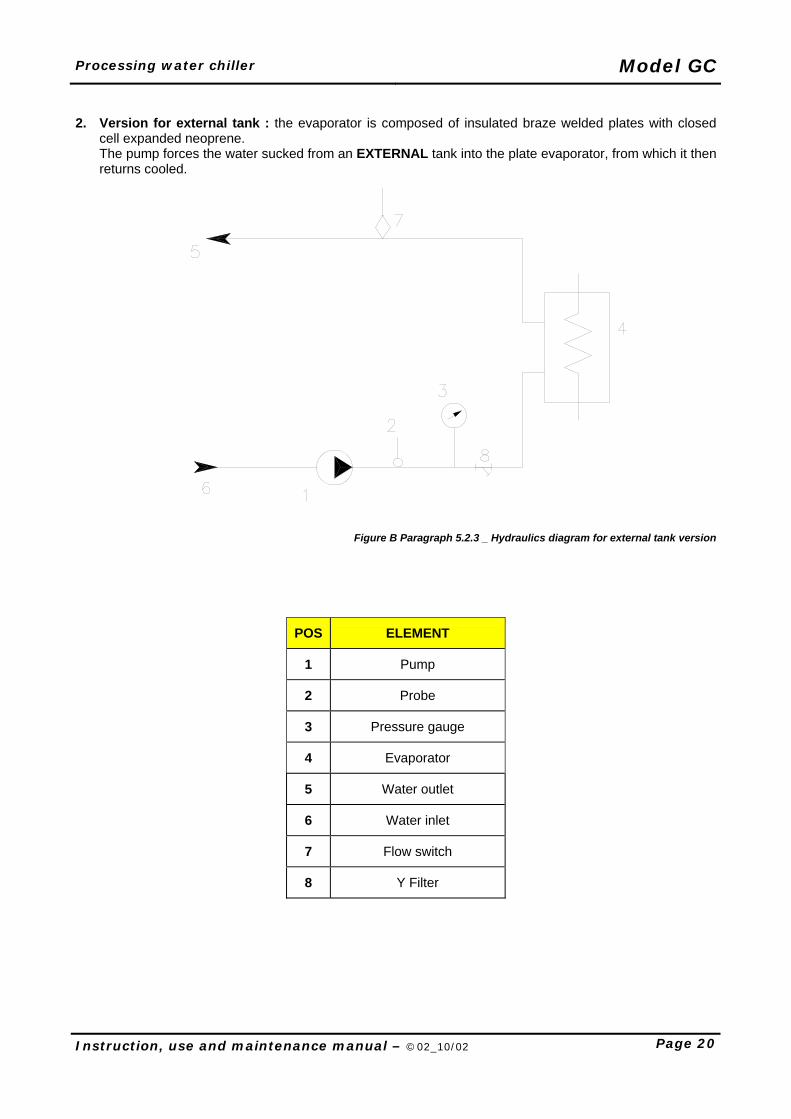
2. Version for external tank : the evaporator is composed of insulated braze welded plates with closed
cell expanded neoprene. The pump forces the water sucked from an EXTERNAL tank into the plate evaporator, from which it then returns cooled.
Figure B Paragraph 5.2.3 _ Hydraulics diagram for external tank version
POS ELEMENT
1 Pump
2 Probe
3 Pressure gauge
4 Evaporator
5 Water outlet
6 Water inlet
7 Flow switch
8 Y Filter
Model GC Processing water chiller
Page 21 Instruction, use and maintenance manual – ©02_10/02
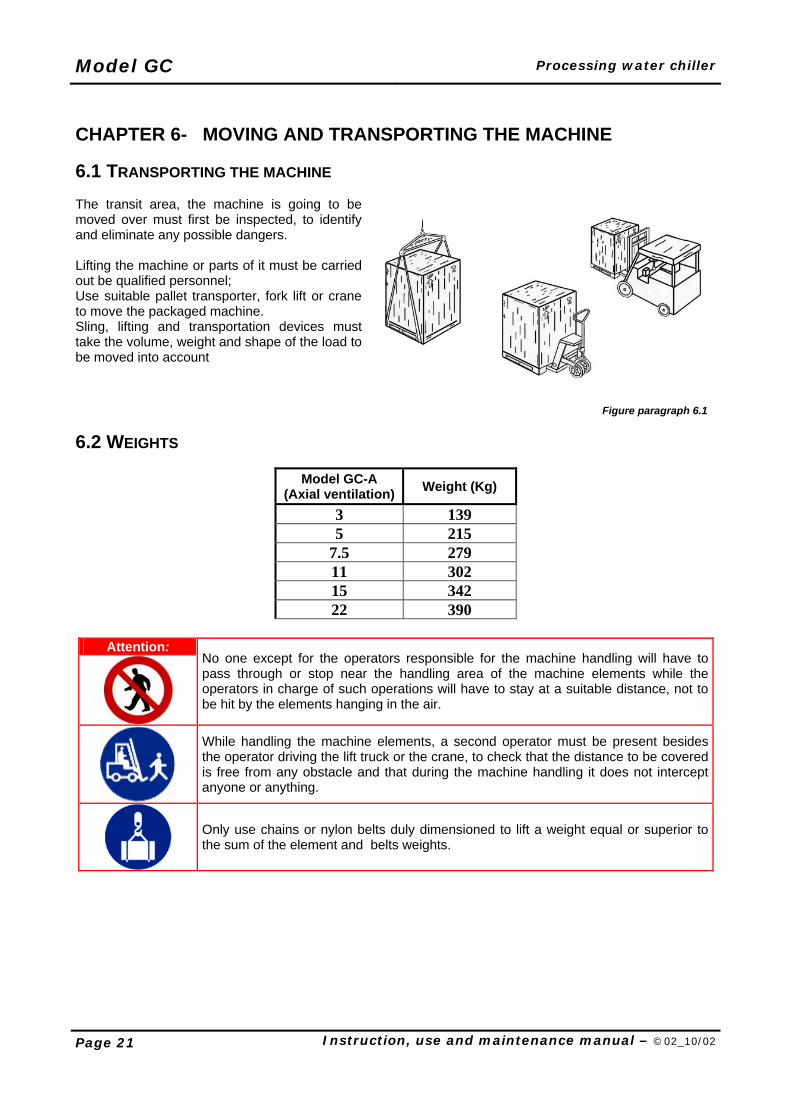
CHAPTER 6- MOVING AND TRANSPORTING THE MACHINE 6.1 TRANSPORTING THE MACHINE The transit area, the machine is going to be moved over must first be inspected, to identify and eliminate any possible dangers. Lifting the machine or parts of it must be carried out be qualified personnel; Use suitable pallet transporter, fork lift or crane to move the packaged machine. Sling, lifting and transportation devices must take the volume, weight and shape of the load to be moved into account
Figure paragraph 6.1
6.2 WEIGHTS
Model GC-A (Axial ventilation) Weight (Kg)
3 139 5 215
7.5 279 11 302 15 342 22 390
Attention:
No one except for the operators responsible for the machine handling will have to pass through or stop near the handling area of the machine elements while the operators in charge of such operations will have to stay at a suitable distance, not to be hit by the elements hanging in the air.
While handling the machine elements, a second operator must be present besides the operator driving the lift truck or the crane, to check that the distance to be covered is free from any obstacle and that during the machine handling it does not intercept anyone or anything.
Only use chains or nylon belts duly dimensioned to lift a weight equal or superior to the sum of the element and belts weights.
Processing water chiller Model GC
Instruction, use and maintenance manual – ©02_10/02 Page 22
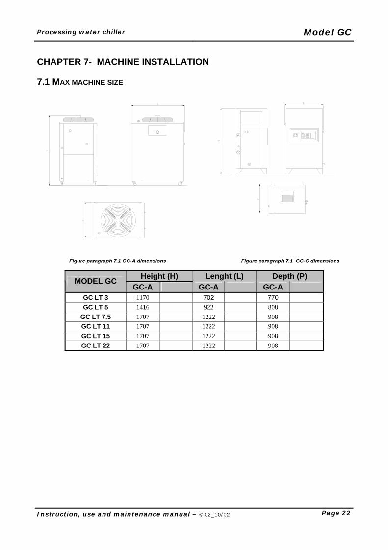
CHAPTER 7- MACHINE INSTALLATION 7.1 MAX MACHINE SIZE
Figure paragraph 7.1 GC-A dimensions Figure paragraph 7.1 GC-C dimensions
Height (H) Lenght (L) Depth (P) MODEL GC GC-A GC-A GC-A
GC LT 3 1170 702 770
GC LT 5 1416 922 808
GC LT 7.5 1707 1222 908
GC LT 11 1707 1222 908
GC LT 15 1707 1222 908
GC LT 22 1707 1222 908
Model GC Processing water chiller
Page 23 Instruction, use and maintenance manual – ©02_10/02
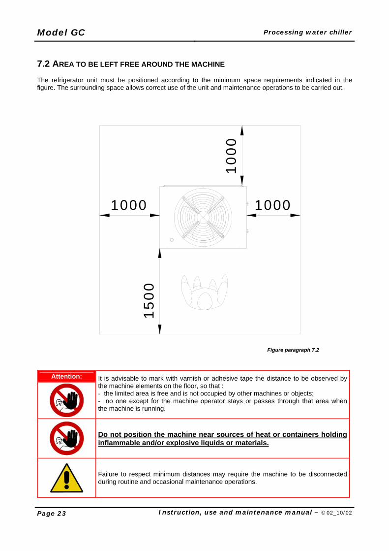
7.2 AREA TO BE LEFT FREE AROUND THE MACHINE The refrigerator unit must be positioned according to the minimum space requirements indicated in the figure. The surrounding space allows correct use of the unit and maintenance operations to be carried out.
1 500
1000
1000
1000
Figure paragraph 7.2
Attention:
It is advisable to mark with varnish or adhesive tape the distance to be observed by the machine elements on the floor, so that : - the limited area is free and is not occupied by other machines or objects; - no one except for the machine operator stays or passes through that area when the machine is running.
Do not position the machine near sources of heat or containers holding inflammable and/or explosive liquids or materials.
Failure to respect minimum distances may require the machine to be disconnected during routine and occasional maintenance operations.
Processing water chiller Model GC
Instruction, use and maintenance manual – ©02_10/02 Page 24
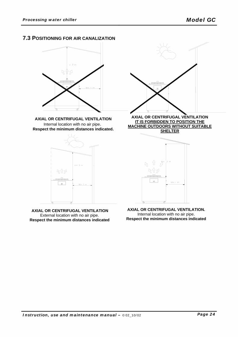
7.3 POSITIONING FOR AIR CANALIZATION
AXIAL OR CENTRIFUGAL VENTILATION Internal location with no air pipe.
Respect the minimum distances indicated.
AXIAL OR CENTRIFUGAL VENTILATION IT IS FORBIDDEN TO POSITION THE
MACHINE OUTDOORS WITHOUT SUITABLE SHELTER
AXIAL OR CENTRIFUGAL VENTILATION External location with no air pipe.
Respect the minimum distances indicated
AXIAL OR CENTRIFUGAL VENTILATION. Internal location with no air pipe.
Respect the minimum distances indicated
Model GC Processing water chiller
Page 25 Instruction, use and maintenance manual – ©02_10/02
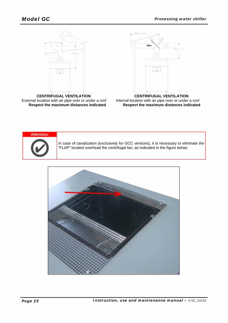
CENTRIFUGAL VENTILATION CENTRIFUGAL VENTILATION External location with air pipe over or under a roof Internal location with air pipe over or under a roof
Respect the maximum distances indicated Respect the maximum distances indicated
Attention:
In case of canalization (exclusively for GCC versions), it is necessary to eliminate the “FLAP” located overhead the centrifugal fan, as indicated in the figure below.
Processing water chiller Model GC
Instruction, use and maintenance manual – ©02_10/02 Page 26
CHAPTER 8- ASSEMBLAGE AND PREPARATION OF THE MACHINE TO WORK
8.1 PRELIMINARY CONTROL CHECKS Upon receipt of the machine, it is advisable to check all the elements composing it. Please find below a brief list of the elements to be checked: 1. Check that the machine completely assembled 2. Control the presence of possible accessories and the option required 3. Control that there are all the mechanic protection 8.2 CONTROL CHECK ON ANY DAMAGE THE MACHINE MAY HAVE SUFFERED DURING
TRANSPORT In order to check whether the machine has been subject to any damage during transport, check all protruding machine parts as described above: • The control panel with the relevant control organs, • the mechanic safety devices. If any of the machine packing has been damaged, proceed as follows:
Easily recognizable damage on exterior or on machine parts: these must be signalled immediately after delivery to the transport company, and confirmed in writing by the transporter.
Damage not immediately recognizable: This must be declared to the transport company within the
period prescribed by law.
Serious damage: All damage must be assessed by a qualified technician charged by the transport company or the insurance company.
Attention:
Any complaint concerning a possible lack in the material supplied with the machine must be notified within 10 days upon receipt.
Model GC Processing water chiller
Page 27 Instruction, use and maintenance manual – ©02_10/02
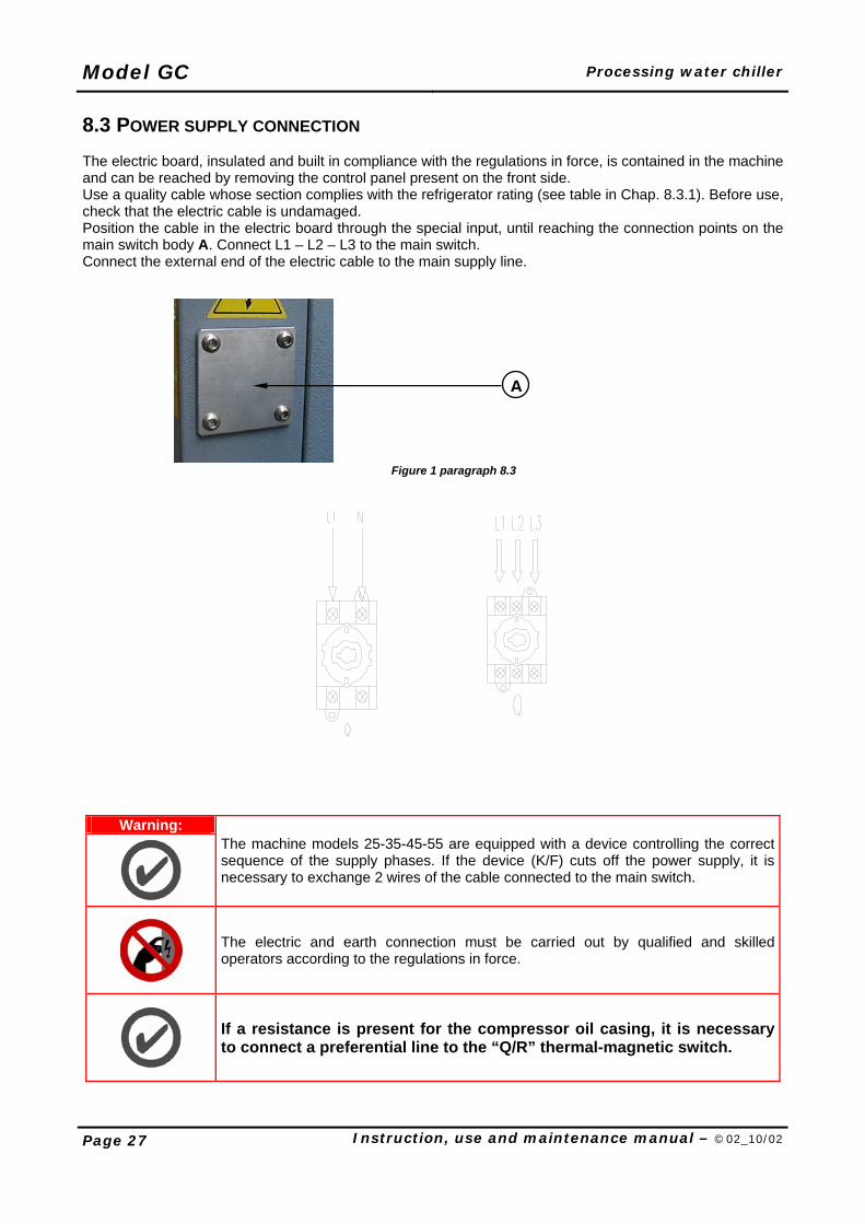
8.3 POWER SUPPLY CONNECTION The electric board, insulated and built in compliance with the regulations in force, is contained in the machine and can be reached by removing the control panel present on the front side. Use a quality cable whose section complies with the refrigerator rating (see table in Chap. 8.3.1). Before use, check that the electric cable is undamaged. Position the cable in the electric board through the special input, until reaching the connection points on the main switch body A. Connect L1 – L2 – L3 to the main switch. Connect the external end of the electric cable to the main supply line.
Figure 1 paragraph 8.3
Warning:
The machine models 25-35-45-55 are equipped with a device controlling the correct sequence of the supply phases. If the device (K/F) cuts off the power supply, it is necessary to exchange 2 wires of the cable connected to the main switch.
The electric and earth connection must be carried out by qualified and skilled operators according to the regulations in force.
If a resistance is present for the compressor oil casing, it is necessary to connect a preferential line to the “Q/R” thermal-magnetic switch.
A
Processing water chiller Model GC
Instruction, use and maintenance manual – ©02_10/02 Page 28
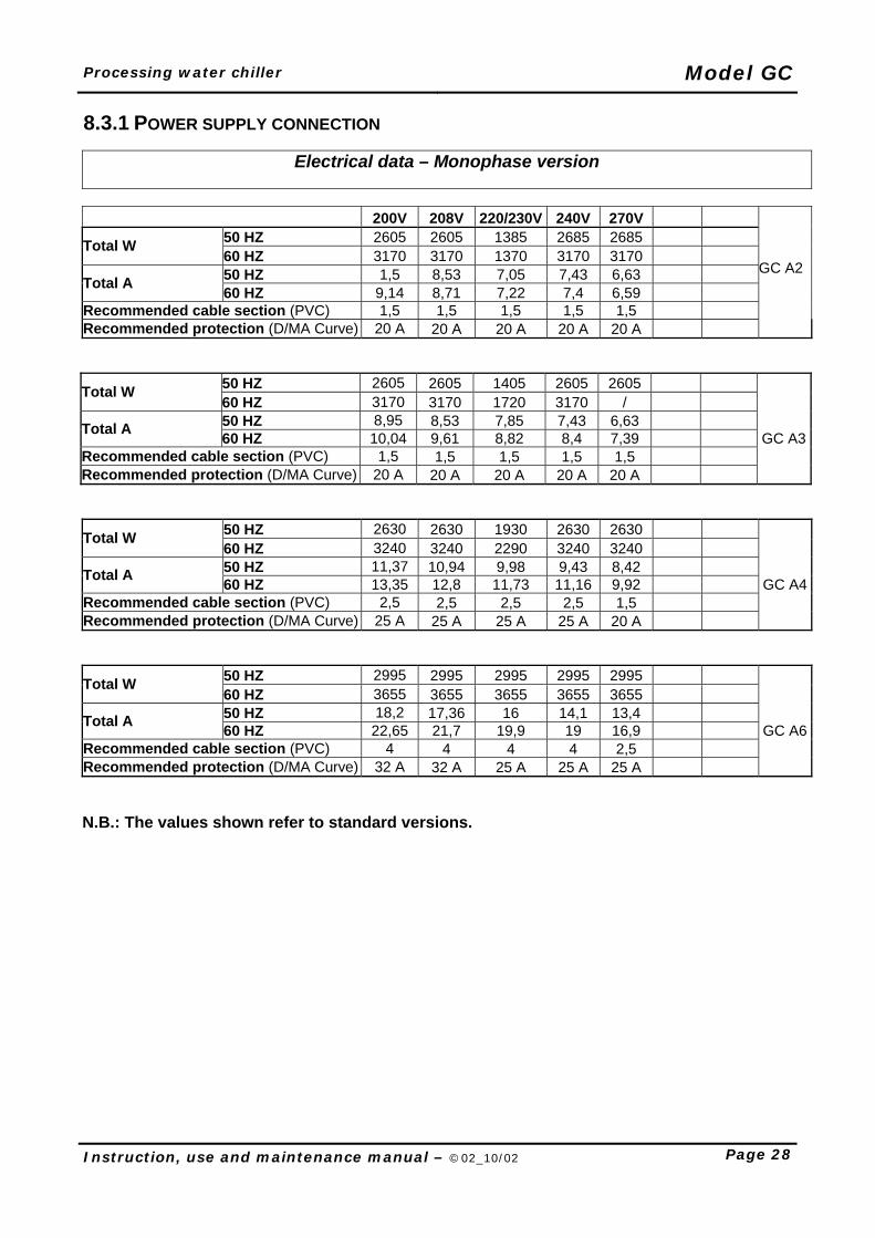
8.3.1 POWER SUPPLY CONNECTION
50 HZ 2605 2605 1385 2685 2685 Total W 60 HZ 3170 3170 1370 3170 3170 50 HZ 1,5 8,53 7,05 7,43 6,63 Total A 60 HZ 9,14 8,71 7,22 7,4 6,59
Recommended cable section (PVC) 1,5 1,5 1,5 1,5 1,5
Recommended protection (D/MA Curve) 20 A 20 A 20 A 20 A 20 A
50 HZ 2605 2605 1405 2605 2605 Total W 60 HZ 3170 3170 1720 3170 / 50 HZ 8,95 8,53 7,85 7,43 6,63 Total A 60 HZ 10,04 9,61 8,82 8,4 7,39 GC A3
Recommended cable section (PVC) 1,5 1,5 1,5 1,5 1,5 Recommended protection (D/MA Curve) 20 A 20 A 20 A 20 A 20 A
50 HZ 2630 2630 1930 2630 2630 Total W 60 HZ 3240 3240 2290 3240 3240 50 HZ 11,37 10,94 9,98 9,43 8,42 Total A 60 HZ 13,35 12,8 11,73 11,16 9,92 GC A4
Recommended cable section (PVC) 2,5 2,5 2,5 2,5 1,5 Recommended protection (D/MA Curve) 25 A 25 A 25 A 25 A 20 A
50 HZ 2995 2995 2995 2995 2995 Total W 60 HZ 3655 3655 3655 3655 3655 50 HZ 18,2 17,36 16 14,1 13,4 Total A 60 HZ 22,65 21,7 19,9 19 16,9 GC A6
Recommended cable section (PVC) 4 4 4 4 2,5 Recommended protection (D/MA Curve) 32 A 32 A 25 A 25 A 25 A N.B.: The values shown refer to standard versions.
Electrical data – Monophase version 200V 208V 220/230V 240V 270V
GC A2
Model GC Processing water chiller
Page 29 Instruction, use and maintenance manual – ©02_10/02
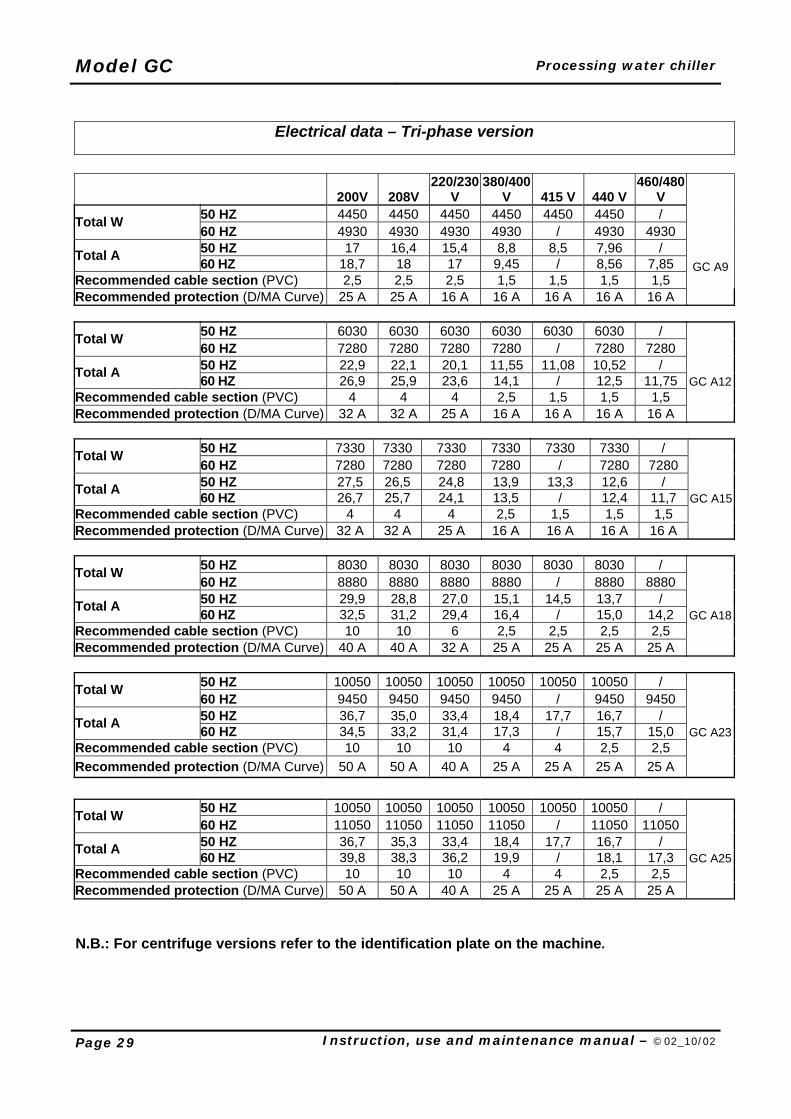
Electrical data – Tri-phase version
200V 208V 220/230
V 380/400
V 415 V 440 V 460/480
V 50 HZ 4450 4450 4450 4450 4450 4450 / Total W 60 HZ 4930 4930 4930 4930 / 4930 4930 50 HZ 17 16,4 15,4 8,8 8,5 7,96 / Total A 60 HZ 18,7 18 17 9,45 / 8,56 7,85
Recommended cable section (PVC) 2,5 2,5 2,5 1,5 1,5 1,5 1,5
GC A9
Recommended protection (D/MA Curve) 25 A 25 A 16 A 16 A 16 A 16 A 16 A
50 HZ 6030 6030 6030 6030 6030 6030 / Total W 60 HZ 7280 7280 7280 7280 / 7280 7280 50 HZ 22,9 22,1 20,1 11,55 11,08 10,52 / Total A 60 HZ 26,9 25,9 23,6 14,1 / 12,5 11,75 GC A12
Recommended cable section (PVC) 4 4 4 2,5 1,5 1,5 1,5 Recommended protection (D/MA Curve) 32 A 32 A 25 A 16 A 16 A 16 A 16 A
50 HZ 7330 7330 7330 7330 7330 7330 / Total W 60 HZ 7280 7280 7280 7280 / 7280 7280 50 HZ 27,5 26,5 24,8 13,9 13,3 12,6 / Total A 60 HZ 26,7 25,7 24,1 13,5 / 12,4 11,7 GC A15
Recommended cable section (PVC) 4 4 4 2,5 1,5 1,5 1,5 Recommended protection (D/MA Curve) 32 A 32 A 25 A 16 A 16 A 16 A 16 A
50 HZ 8030 8030 8030 8030 8030 8030 / Total W 60 HZ 8880 8880 8880 8880 / 8880 8880 50 HZ 29,9 28,8 27,0 15,1 14,5 13,7 / Total A 60 HZ 32,5 31,2 29,4 16,4 / 15,0 14,2 GC A18
Recommended cable section (PVC) 10 10 6 2,5 2,5 2,5 2,5 Recommended protection (D/MA Curve) 40 A 40 A 32 A 25 A 25 A 25 A 25 A
50 HZ 10050 10050 10050 10050 10050 10050 / Total W 60 HZ 9450 9450 9450 9450 / 9450 9450 50 HZ 36,7 35,0 33,4 18,4 17,7 16,7 / Total A 60 HZ 34,5 33,2 31,4 17,3 / 15,7 15,0 GC A23
Recommended cable section (PVC) 10 10 10 4 4 2,5 2,5 Recommended protection (D/MA Curve) 50 A 50 A 40 A 25 A 25 A 25 A 25 A
50 HZ 10050 10050 10050 10050 10050 10050 / Total W 60 HZ 11050 11050 11050 11050 / 11050 11050 50 HZ 36,7 35,3 33,4 18,4 17,7 16,7 / Total A 60 HZ 39,8 38,3 36,2 19,9 / 18,1 17,3 GC A25
Recommended cable section (PVC) 10 10 10 4 4 2,5 2,5 Recommended protection (D/MA Curve) 50 A 50 A 40 A 25 A 25 A 25 A 25 A N.B.: For centrifuge versions refer to the identification plate on the machine.
Processing water chiller Model GC
Instruction, use and maintenance manual – ©02_10/02 Page 30
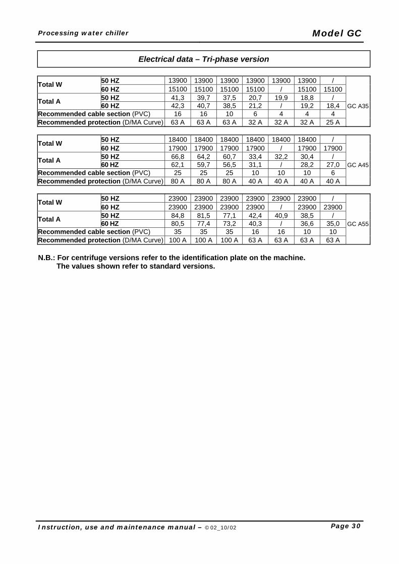
Electrical data – Tri-phase version
50 HZ 13900 13900 13900 13900 13900 13900 / Total W 60 HZ 15100 15100 15100 15100 / 15100 15100 50 HZ 41,3 39,7 37,5 20,7 19,9 18,8 / Total A 60 HZ 42,3 40,7 38,5 21,2 / 19,2 18,4 GC A35
Recommended cable section (PVC) 16 16 10 6 4 4 4 Recommended protection (D/MA Curve) 63 A 63 A 63 A 32 A 32 A 32 A 25 A
50 HZ 18400 18400 18400 18400 18400 18400 / Total W 60 HZ 17900 17900 17900 17900 / 17900 17900 50 HZ 66,8 64,2 60,7 33,4 32,2 30,4 / Total A 60 HZ 62,1 59,7 56,5 31,1 / 28,2 27,0 GC A45
Recommended cable section (PVC) 25 25 25 10 10 10 6 Recommended protection (D/MA Curve) 80 A 80 A 80 A 40 A 40 A 40 A 40 A
50 HZ 23900 23900 23900 23900 23900 23900 / Total W 60 HZ 23900 23900 23900 23900 / 23900 23900 50 HZ 84,8 81,5 77,1 42,4 40,9 38,5 / Total A 60 HZ 80,5 77,4 73,2 40,3 / 36,6 35,0 GC A55
Recommended cable section (PVC) 35 35 35 16 16 10 10 Recommended protection (D/MA Curve) 100 A 100 A 100 A 63 A 63 A 63 A 63 A N.B.: For centrifuge versions refer to the identification plate on the machine. The values shown refer to standard versions.
Model GC Processing water chiller
Page 31 Instruction, use and maintenance manual – ©02_10/02
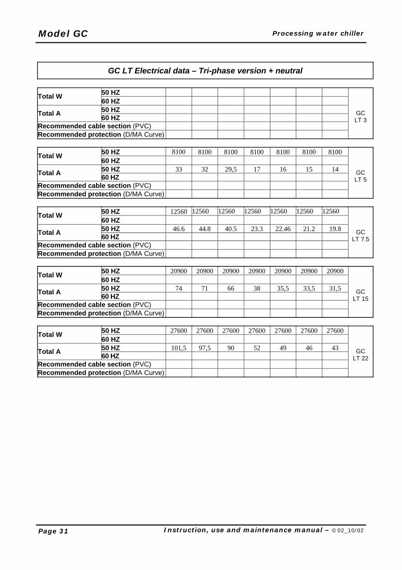
GC LT Electrical data – Tri-phase version + neutral
50 HZ Total W 60 HZ 50 HZ Total A 60 HZ
Recommended cable section (PVC) Recommended protection (D/MA Curve)
GC LT 3
50 HZ 8100 8100 8100 8100 8100 8100 8100 Total W 60 HZ 50 HZ 33 32 29,5 17 16 15 14 Total A 60 HZ
Recommended cable section (PVC) Recommended protection (D/MA Curve)
GC LT 5
50 HZ 12560 12560 12560 12560 12560 12560 12560 Total W 60 HZ 50 HZ 46.6 44.8 40.5 23.3 22.46 21.2 19.8 Total A 60 HZ
Recommended cable section (PVC) Recommended protection (D/MA Curve)
GC LT 7.5
50 HZ 20900 20900 20900 20900 20900 20900 20900 Total W 60 HZ 50 HZ 74 71 66 38 35,5 33,5 31,5 Total A 60 HZ
Recommended cable section (PVC) Recommended protection (D/MA Curve)
GC LT 15
50 HZ 27600 27600 27600 27600 27600 27600 27600 Total W 60 HZ 50 HZ 101,5 97,5 90 52 49 46 43 Total A 60 HZ
Recommended cable section (PVC) Recommended protection (D/MA Curve)
GC LT 22
Processing water chiller Model GC
Instruction, use and maintenance manual – ©02_10/02 Page 32
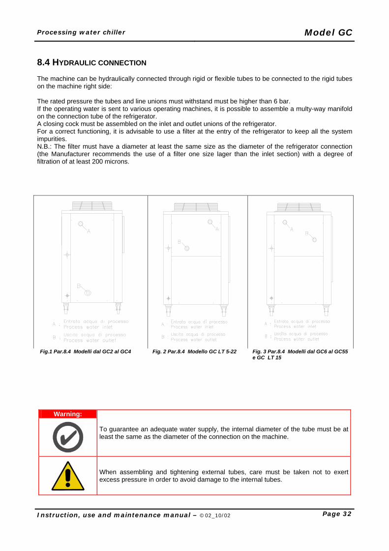
8.4 HYDRAULIC CONNECTION The machine can be hydraulically connected through rigid or flexible tubes to be connected to the rigid tubes on the machine right side: The rated pressure the tubes and line unions must withstand must be higher than 6 bar. If the operating water is sent to various operating machines, it is possible to assemble a multy-way manifold on the connection tube of the refrigerator. A closing cock must be assembled on the inlet and outlet unions of the refrigerator. For a correct functioning, it is advisable to use a filter at the entry of the refrigerator to keep all the system impurities. N.B.: The filter must have a diameter at least the same size as the diameter of the refrigerator connection (the Manufacturer recommends the use of a filter one size lager than the inlet section) with a degree of filtration of at least 200 microns.
Fig.1 Par.8.4 Modelli dal GC2 al GC4 Fig. 2 Par.8.4 Modello GC LT 5-22 Fig. 3 Par.8.4 Modelli dal GC6 al GC55
e GC LT 15
Warning:
To guarantee an adequate water supply, the internal diameter of the tube must be at least the same as the diameter of the connection on the machine.
When assembling and tightening external tubes, care must be taken not to exert excess pressure in order to avoid damage to the internal tubes.
Model GC Processing water chiller
Page 33 Instruction, use and maintenance manual – ©02_10/02
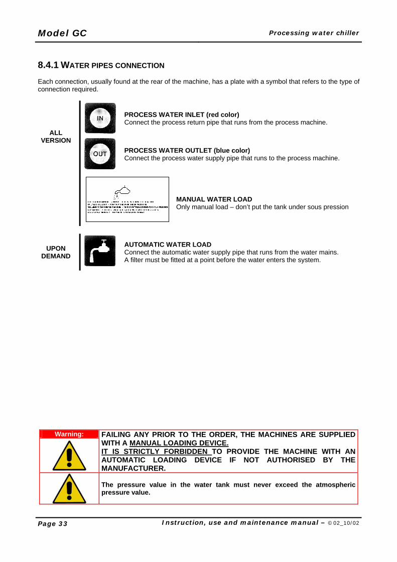
8.4.1 WATER PIPES CONNECTION Each connection, usually found at the rear of the machine, has a plate with a symbol that refers to the type of connection required.
PROCESS WATER INLET (red color) Connect the process return pipe that runs from the process machine.
ALL VERSION
PROCESS WATER OUTLET (blue color) Connect the process water supply pipe that runs to the process machine.
MANUAL WATER LOAD Only manual load – don’t put the tank under sous pression
UPON DEMAND
AUTOMATIC WATER LOAD Connect the automatic water supply pipe that runs from the water mains. A filter must be fitted at a point before the water enters the system.
Warning:
FAILING ANY PRIOR TO THE ORDER, THE MACHINES ARE SUPPLIED WITH A MANUAL LOADING DEVICE. IT IS STRICTLY FORBIDDEN TO PROVIDE THE MACHINE WITH AN AUTOMATIC LOADING DEVICE IF NOT AUTHORISED BY THE MANUFACTURER.
The pressure value in the water tank must never exceed the atmospheric pressure value.
Processing water chiller Model GC
Instruction, use and maintenance manual – ©02_10/02 Page 34
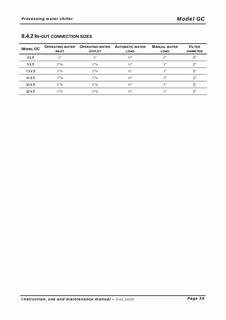
8.4.2 IN-OUT CONNECTION SIZES
MODEL GC OPERATING WATER INLET
OPERATING WATER OUTLET
AUTOMATIC WATER LOAD
MANUAL WATER LOAD
FILTER DIAMETER
3 LT 1” 1” ½” 1” 2” 5 LT 1”¼ 1”¼ ½” 1” 2”
7.5 LT 1”¼ 1”¼ ½” 1” 2” 11 LT 1”¼ 1”¼ ½” 1” 2” 15 LT 1”¼ 1”¼ ½” 1” 2” 22 LT 1”¼ 1”¼ ½” 1” 2”
Model GC Processing water chiller
Page 35 Instruction, use and maintenance manual – ©02_10/02
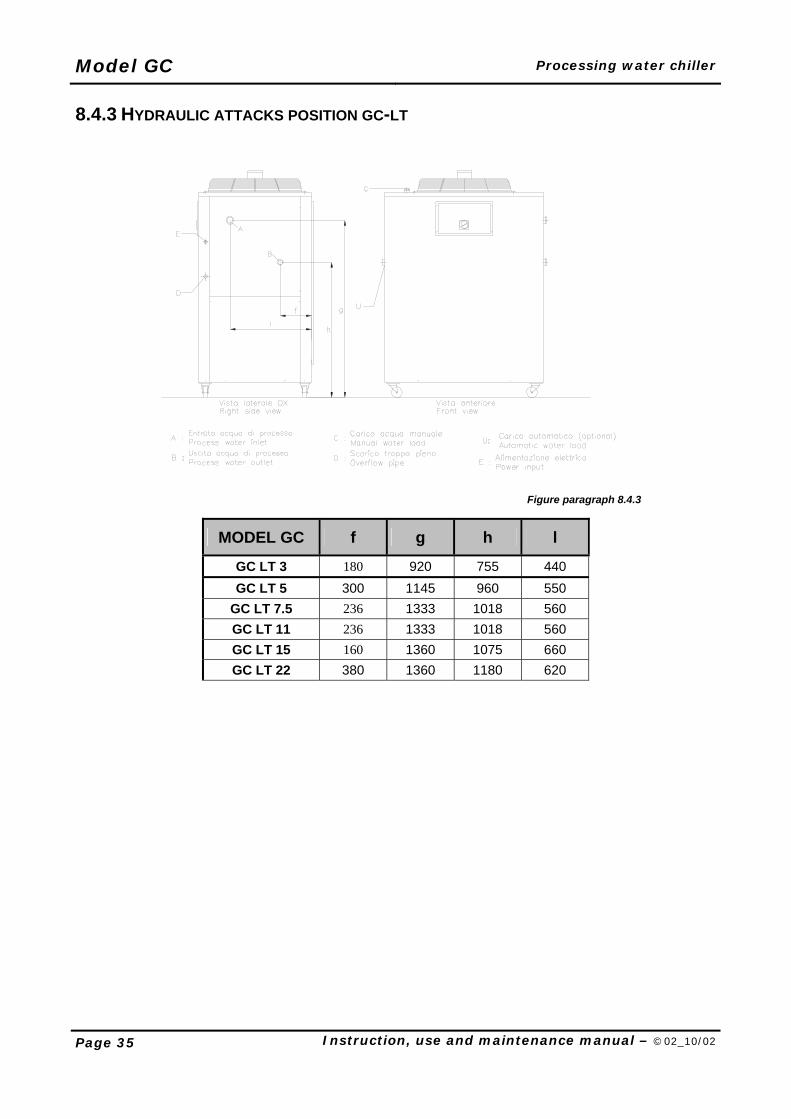
8.4.3 HYDRAULIC ATTACKS POSITION GC-LT
Figure paragraph 8.4.3
MODEL GC f g h l
GC LT 3 180 920 755 440 GC LT 5 300 1145 960 550
GC LT 7.5 236 1333 1018 560 GC LT 11 236 1333 1018 560 GC LT 15 160 1360 1075 660 GC LT 22 380 1360 1180 620
Processing water chiller Model GC
Instruction, use and maintenance manual – ©02_10/02 Page 36
8.5 USE OF ANTIFREEZE IN THE PROCESS WATER The machine can operate without antifreeze up to a preset temperature of no less than +5°C. In case of temperatures lower than +5°C, it is necessary to use an anti-freeze agent. Even at ambient temperatures above 5°C use of antifreeze is advisable as it confers better flow properties on the water in the system. Check that the antifreeze used does not contain substances that may corrode the basic materials used to manufacture the machine (steel, copper and aluminium). The Builder recommends the use of the following antifreeze liquid KLEENTEK CL3295 (containing Anti-freeze agent).
DOSES OF ANTIFREEZING AGENT TO BE USED ACCORDING TO THE TEMPERATURE OF THE OPERATING WATER
PROCESS WATER TEMPERATURE +5° C 0° C -5° C -10°C -20°C -30°C
Percentage of antifreeze 10% 20% 25% 30% 40% 45%
DOSES OF ANTIFREEZING AGENT TO THE USED ACCORDING TO THE ROOM TEMPERATURE
ENVIRONMENTAL TEMPERATURE +5° C 0° C -5° C -10°C -15°C
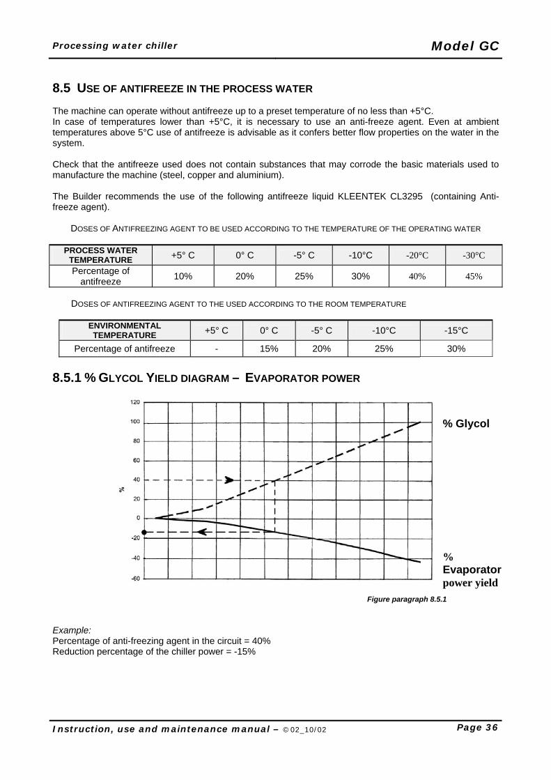
Percentage of antifreeze - 15% 20% 25% 30% 8.5.1 % GLYCOL YIELD DIAGRAM – EVAPORATOR POWER
Figure paragraph 8.5.1
Example: Percentage of anti-freezing agent in the circuit = 40% Reduction percentage of the chiller power = -15%
% Glycol
% Evaporator power yield
Model GC Processing water chiller
Page 37 Instruction, use and maintenance manual – ©02_10/02
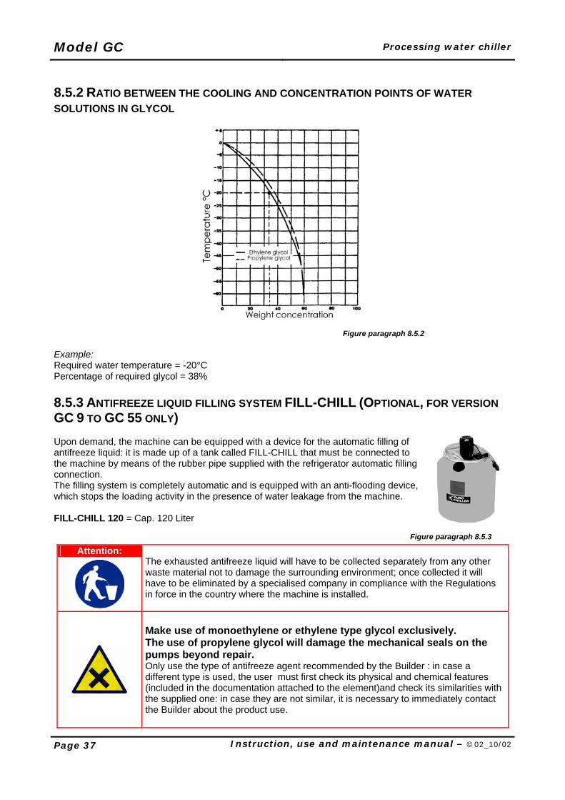
8.5.2 RATIO BETWEEN THE COOLING AND CONCENTRATION POINTS OF WATER SOLUTIONS IN GLYCOL
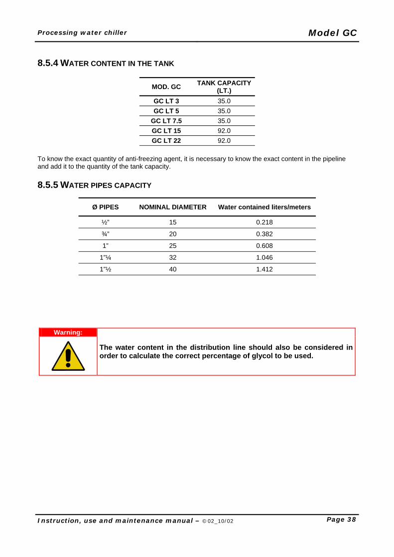
Figure paragraph 8.5.2 Example: Required water temperature = -20°C Percentage of required glycol = 38% 8.5.3 ANTIFREEZE LIQUID FILLING SYSTEM FILL-CHILL (OPTIONAL, FOR VERSION GC 9 TO GC 55 ONLY) Upon demand, the machine can be equipped with a device for the automatic filling of antifreeze liquid: it is made up of a tank called FILL-CHILL that must be connected to the machine by means of the rubber pipe supplied with the refrigerator automatic filling connection. The filling system is completely automatic and is equipped with an anti-flooding device, which stops the loading activity in the presence of water leakage from the machine. FILL-CHILL 120 = Cap. 120 Liter
Figure paragraph 8.5.3
Attention:
The exhausted antifreeze liquid will have to be collected separately from any other waste material not to damage the surrounding environment; once collected it will have to be eliminated by a specialised company in compliance with the Regulations in force in the country where the machine is installed.
Make use of monoethylene or ethylene type glycol exclusively. The use of propylene glycol will damage the mechanical seals on the pumps beyond repair. Only use the type of antifreeze agent recommended by the Builder : in case a different type is used, the user must first check its physical and chemical features (included in the documentation attached to the element)and check its similarities with the supplied one: in case they are not similar, it is necessary to immediately contact the Builder about the product use.
Processing water chiller Model GC
Instruction, use and maintenance manual – ©02_10/02 Page 38
8.5.4 WATER CONTENT IN THE TANK
MOD. GC TANK CAPACITY (LT.)
GC LT 3 35.0 GC LT 5 35.0
GC LT 7.5 35.0 GC LT 15 92.0 GC LT 22 92.0
To know the exact quantity of anti-freezing agent, it is necessary to know the exact content in the pipeline and add it to the quantity of the tank capacity. 8.5.5 WATER PIPES CAPACITY
Ø PIPES NOMINAL DIAMETER Water contained liters/meters
½” 15 0.218
¾” 20 0.382
1” 25 0.608
1”¼ 32 1.046
1”½ 40 1.412
Warning:
The water content in the distribution line should also be considered in order to calculate the correct percentage of glycol to be used.
Model GC Processing water chiller
Page 39 Instruction, use and maintenance manual – ©02_10/02
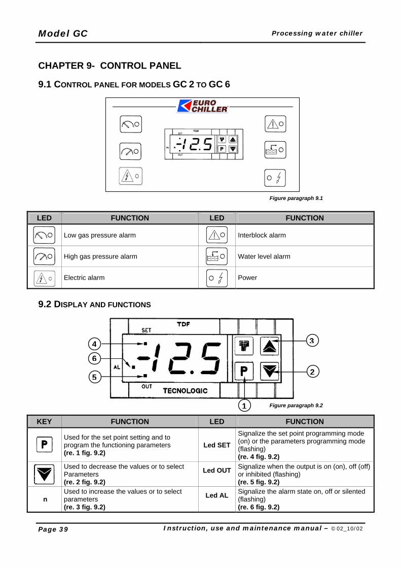
CHAPTER 9- CONTROL PANEL 9.1 CONTROL PANEL FOR MODELS GC 2 TO GC 6
Figure paragraph 9.1
LED FUNCTION LED FUNCTION
Low gas pressure alarm
Interblock alarm
High gas pressure alarm
Water level alarm
Electric alarm
Power
9.2 DISPLAY AND FUNCTIONS
Figure paragraph 9.2
KEY FUNCTION LED FUNCTION
Used for the set point setting and to program the functioning parameters (re. 1 fig. 9.2)
Led SET Signalize the set point programming mode (on) or the parameters programming mode (flashing) (re. 4 fig. 9.2)
Used to decrease the values or to select Parameters (re. 2 fig. 9.2)
Led OUT
Signalize when the output is on (on), off (off) or inhibited (flashing) (re. 5 fig. 9.2)
n Used to increase the values or to select parameters (re. 3 fig. 9.2)
Led AL
Signalize the alarm state on, off or silented (flashing) (re. 6 fig. 9.2)
3
2
1
5
4
6
Processing water chiller Model GC
Instruction, use and maintenance manual – ©02_10/02 Page 40
9.2.1 SET POINT PROGRAMMING Press key then release it, led SET will flash and the SET value will be shown on display. To modify press key so as to increase value or so as to decrease it. These keys count one digit at a time but if the keys are pressed for over one second the value increases or decreases fast and after two seconds the speed increases even more, so as to reach the desired value immediately. The outgoing from the Set programming mode occurs automatically by not pressing any key for about 5 seconds, thus the temperature process value will again be displayed. 9.3 CONTROL PANEL FOR MODELS GC 9 TO GC 55
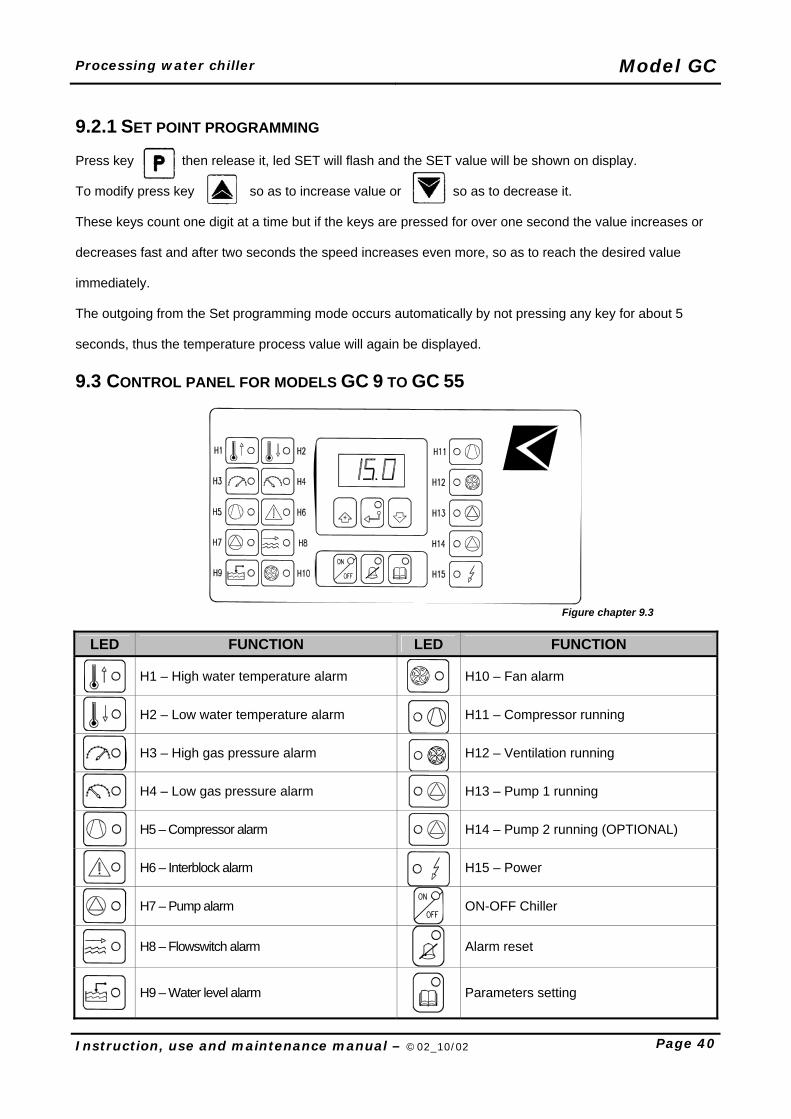
Figure chapter 9.3
LED FUNCTION LED FUNCTION
H1 – High water temperature alarm
H10 – Fan alarm
H2 – Low water temperature alarm
H11 – Compressor running
H3 – High gas pressure alarm
H12 – Ventilation running
H4 – Low gas pressure alarm
H13 – Pump 1 running
H5 – Compressor alarm
H14 – Pump 2 running (OPTIONAL)
H6 – Interblock alarm
H15 – Power
H7 – Pump alarm
ON-OFF Chiller
H8 – Flowswitch alarm
Alarm reset
H9 – Water level alarm
Parameters setting
Model GC Processing water chiller
Page 41 Instruction, use and maintenance manual – ©02_10/02
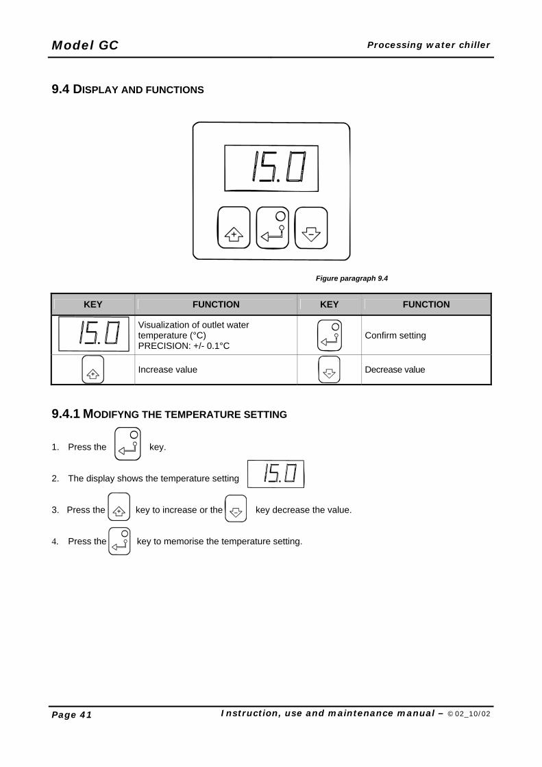
9.4 DISPLAY AND FUNCTIONS
Figure paragraph 9.4
KEY FUNCTION KEY FUNCTION
Visualization of outlet water temperature (°C) PRECISION: +/- 0.1°C
Confirm setting
Increase value
Decrease value
9.4.1 MODIFYNG THE TEMPERATURE SETTING 1. Press the . key. 2. The display shows the temperature setting 3. Press the key to increase or the key decrease the value.
4. Press the key to memorise the temperature setting.
Processing water chiller Model GC
Instruction, use and maintenance manual – ©02_10/02 Page 42
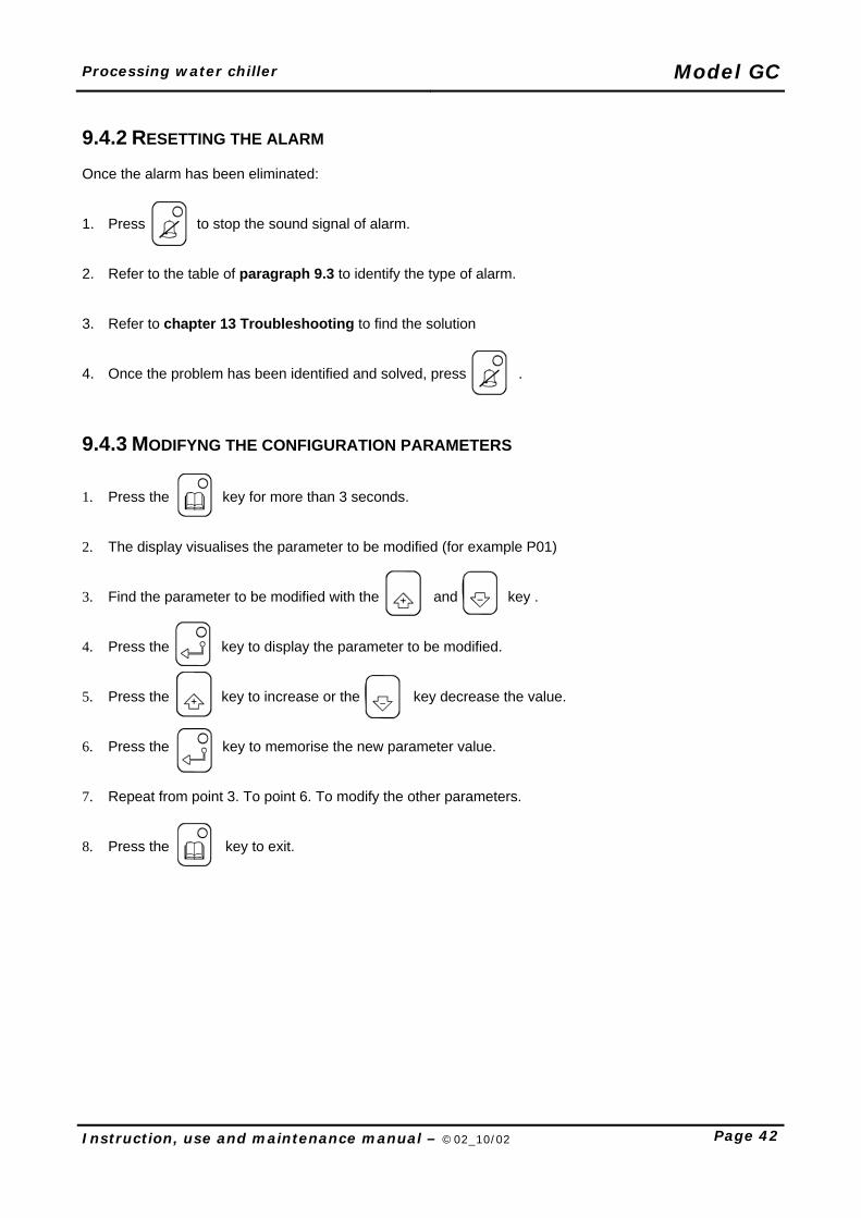
9.4.2 RESETTING THE ALARM Once the alarm has been eliminated: 1. Press to stop the sound signal of alarm. 2. Refer to the table of paragraph 9.3 to identify the type of alarm. 3. Refer to chapter 13 Troubleshooting to find the solution 4. Once the problem has been identified and solved, press . 9.4.3 MODIFYNG THE CONFIGURATION PARAMETERS 1. Press the key for more than 3 seconds. 2. The display visualises the parameter to be modified (for example P01) 3. Find the parameter to be modified with the and key . 4. Press the key to display the parameter to be modified. 5. Press the key to increase or the key decrease the value. 6. Press the key to memorise the new parameter value. 7. Repeat from point 3. To point 6. To modify the other parameters. 8. Press the key to exit.
Model GC Processing water chiller
Page 43 Instruction, use and maintenance manual – ©02_10/02
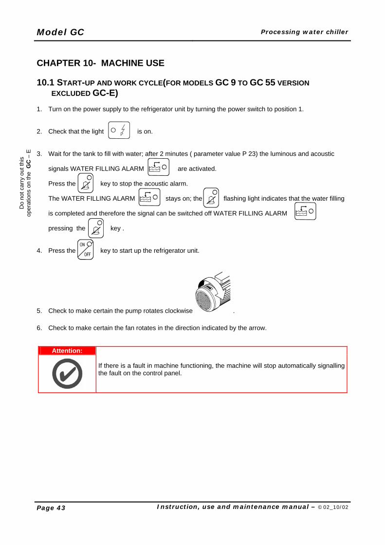
CHAPTER 10- MACHINE USE 10.1 START-UP AND WORK CYCLE(FOR MODELS GC 9 TO GC 55 VERSION
EXCLUDED GC-E) 1. Turn on the power supply to the refrigerator unit by turning the power switch to position 1. 2. Check that the light is on. 3. Wait for the tank to fill with water; after 2 minutes ( parameter value P 23) the luminous and acoustic
signals WATER FILLING ALARM are activated.
Press the key to stop the acoustic alarm. The WATER FILLING ALARM stays on; the flashing light indicates that the water filling is completed and therefore the signal can be switched off WATER FILLING ALARM pressing the key .
4. Press the key to start up the refrigerator unit.
5. Check to make certain the pump rotates clockwise .
6. Check to make certain the fan rotates in the direction indicated by the arrow.
Attention:
If there is a fault in machine functioning, the machine will stop automatically signalling the fault on the control panel.
Do
not c
arry
out
this
op
erat
ions
on
the
GC
– E
Processing water chiller Model GC
Instruction, use and maintenance manual – ©02_10/02 Page 44
10.2 UNFORESEEN STOPPING DUE TO A POWER CUT In case the machine stops because of a temporary lack of power, the machine will not start running again once the power supply is restored. If the machine supervisor wants that the machine starts automatically once the power supply is restored, he must set the parameter P7 autostart = 1 (only for models 9 to 55). This is poses no danger to people in the vicinity of the machine. 10.3 STOPPING THE MACHINE MANUALLY If the daily or weekly breaks are short, the refrigerator unit can be stopped with the key. If however, the refrigerator unit will remain inactive for long periods (holiday periods or plant stoppages), it is advisable to turn off the power supply by turning the power switch to position 0. In models 2 to 6, act on the main switch.
Attention:
The protection systems on the machine have been provided by the manufacturer to protect the operator during his work on the machine.
If the refrigerator is left switched off for long periods, the danger of freezing due to negative room temperature should be considered. Empty system to avoid this occurring.
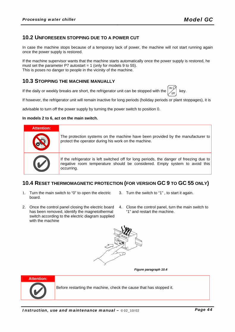
10.4 RESET THERMOMAGNETIC PROTECTION (FOR VERSION GC 9 TO GC 55 ONLY) 1. Turn the main switch to “0” to open the electric
board. 3. Turn the switch to “1” , to start it again.
2. Once the control panel closing the electric board has been removed, identify the magnetothermal switch according to the electric diagram supplied with the machine
4. Close the control panel, turn the main switch to “1” and restart the machine.
Figure paragraph 10.4
Attention:
Before restarting the machine, check the cause that has stopped it.
Model GC Processing water chiller
Page 45 Instruction, use and maintenance manual – ©02_10/02
CHAPTER 11- MACHINE MAINTENANCE I GC series refrigerators function autonomously and continuously and are therefore not fitted with fixed control or command positions. The machine is designed to function continuously for 24 hours per day. This rhythm of work can only be maintained if preventative programmed maintenance measures are adopted. Adequate maintenance is essential for long lasting machine function and optimum performance. The machine must therefore be inspected and receive routine maintenance in order to maintain the technical, productive and safety conditions established by the Manufacturer over time.
Attention:
Any extraordinary modification and maintenance different from the maintenance and replacement interventions described in this chapter must not be carried out without first contacting EUROCHILLER S.r.l. Company, who will decide whether to give their authorisation or not according to each specific case, or will propose the intervention of one of their qualified engineers. Please note that wrong interventions can cause anomalous functioning conditions, cause damages to the machine and be a source of dangers for the personnel using the machine. The Builder is not to be held responsible for the dangers that may derive from the above-mentioned operations.
All maintenance, adjustment setting and replacement operations described in this Instruction manual must be carried out ONLY AFTER having switched off the machine and disconnected the machine plug from the main line socket.
11.1 PROGRAMMED MAINTENANCE To maintain in operation the refrigerator in correct way, perform the operations of maintenance as suitable following:
PERIODICALLY OPERATION OF MAINTENANCE
WEEKLY Cleaning filters panel.
MONTLY Clean the finned group capacitor using compressed air blown from the inside to the outside.
ACCORDING TO USE
Clean the plate evaporator (this operation must be carried out only by skilled operators).
(AFTER 1 WEEK AND ANNUALLY)
To shut all the screw of the electric terminals. Check that all screws are properly tightened on all mechanical parts
A complete maintenance programme can be obtained from Eurochiller Srl technical assistance department.
Processing water chiller Model GC
Instruction, use and maintenance manual – ©02_10/02 Page 46
11.2 MAINTENANCE OPERATIONS FOR AXIAL FANS (VER. GC-A)
1. The fixing of the fan protection grid must be checked periodically(the screws must be shuted).
2. Clean the ventilator blades to eliminate any dust deposit.
Figure paragraph 11.2
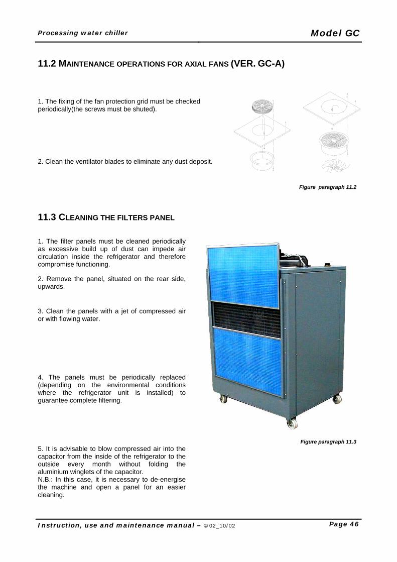
11.3 CLEANING THE FILTERS PANEL 1. The filter panels must be cleaned periodically as excessive build up of dust can impede air circulation inside the refrigerator and therefore compromise functioning.
2. Remove the panel, situated on the rear side, upwards.
3. Clean the panels with a jet of compressed air or with flowing water.
4. The panels must be periodically replaced (depending on the environmental conditions where the refrigerator unit is installed) to guarantee complete filtering.
Figure paragraph 11.3 5. It is advisable to blow compressed air into the capacitor from the inside of the refrigerator to the outside every month without folding the aluminium winglets of the capacitor. N.B.: In this case, it is necessary to de-energise the machine and open a panel for an easier cleaning.
Model GC Processing water chiller
Page 47 Instruction, use and maintenance manual – ©02_10/02
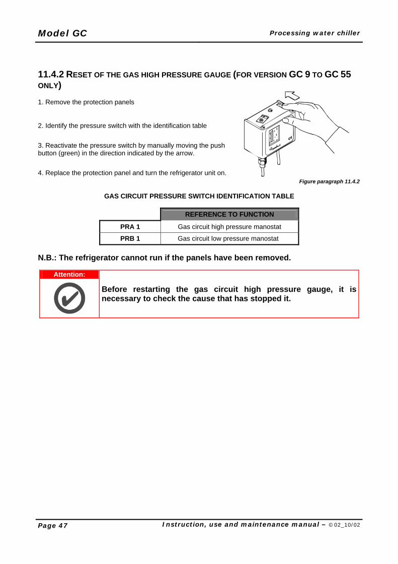
11.4.2 RESET OF THE GAS HIGH PRESSURE GAUGE (FOR VERSION GC 9 TO GC 55 ONLY) 1. Remove the protection panels
2. Identify the pressure switch with the identification table
3. Reactivate the pressure switch by manually moving the push button (green) in the direction indicated by the arrow.
4. Replace the protection panel and turn the refrigerator unit on. Figure paragraph 11.4.2
GAS CIRCUIT PRESSURE SWITCH IDENTIFICATION TABLE
FFF REFERENCE TO FUNCTION
PRA 1 Gas circuit high pressure manostat
PRB 1 Gas circuit low pressure manostat
N.B.: The refrigerator cannot run if the panels have been removed.
Attention:
Before restarting the gas circuit high pressure gauge, it is necessary to check the cause that has stopped it.
Processing water chiller Model GC
Instruction, use and maintenance manual – ©02_10/02 Page 48
11.4 MAINTENANCE ON-OFF LEVEL SWITCHES In case highly encrusting liquids are used, it is advisable to periodically inspect and descale the slide bar and the float, if necessary. If such problem occurs too often, use a filter with a higher protection. 11.5 MAINTENANCE PUMPS When the pump is not used, empty it completely if freezing may be expected. Before restarting the unit, check that the shaft is not jammed and fill the pump casing completely with liquid. It is advisable to use a little quantity of anti-freezing agent to keep the most delicate part of the pump greased. 11.6 MAINTENANCE AN REGULATING DIFFERENTIAL BY-PASS VALVE (FOR VERSIONS
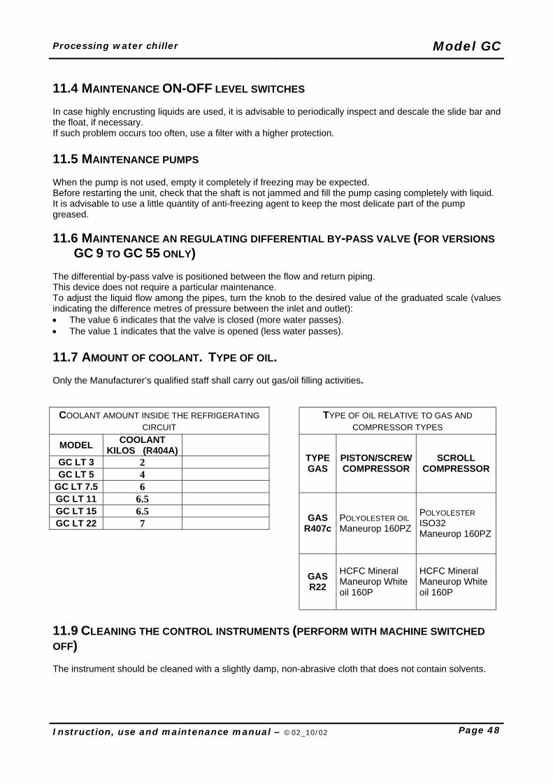
GC 9 TO GC 55 ONLY) The differential by-pass valve is positioned between the flow and return piping. This device does not require a particular maintenance. To adjust the liquid flow among the pipes, turn the knob to the desired value of the graduated scale (values indicating the difference metres of pressure between the inlet and outlet): • The value 6 indicates that the valve is closed (more water passes). • The value 1 indicates that the valve is opened (less water passes). 11.7 AMOUNT OF COOLANT. TYPE OF OIL. Only the Manufacturer’s qualified staff shall carry out gas/oil filling activities.
COOLANT AMOUNT INSIDE THE REFRIGERATING CIRCUIT
TYPE OF OIL RELATIVE TO GAS AND COMPRESSOR TYPES
MODEL COOLANT KILOS (R404A)
GC LT 3 2 GC LT 5 4
GC LT 7.5 6
TYPE GAS
PISTON/SCREW COMPRESSOR
SCROLL COMPRESSOR
GC LT 11 6.5 GC LT 15 6.5 GC LT 22 7
GAS R407c
POLYOLESTER OIL Maneurop 160PZ
POLYOLESTER ISO32 Maneurop 160PZ
GAS R22
HCFC Mineral Maneurop White oil 160P
HCFC Mineral Maneurop White oil 160P
11.9 CLEANING THE CONTROL INSTRUMENTS (PERFORM WITH MACHINE SWITCHED OFF) The instrument should be cleaned with a slightly damp, non-abrasive cloth that does not contain solvents.
Model GC Processing water chiller
Page 49 Instruction, use and maintenance manual – ©02_10/02
CHAPTER 12- MODIFYNG THE PROTECTED PARAMETER (FOR VERSIONS GC 9 TO GC 55 ONLY)
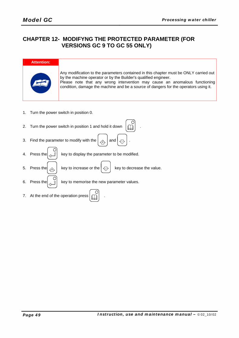
Attention:
Any modification to the parameters contained in this chapter must be ONLY carried out by the machine operator or by the Builder's qualified engineer. Please note that any wrong intervention may cause an anomalous functioning condition, damage the machine and be a source of dangers for the operators using it.
1. Turn the power switch in position 0. 2. Turn the power switch in position 1 and hold it down . 3. Find the parameter to modify with the and . 4. Press the key to display the parameter to be modified. 5. Press the key to increase or the key to decrease the value. 6. Press the key to memorise the new parameter values. 7. At the end of the operation press .
Processing water chiller Model GC
Instruction, use and maintenance manual – ©02_10/02 Page 50
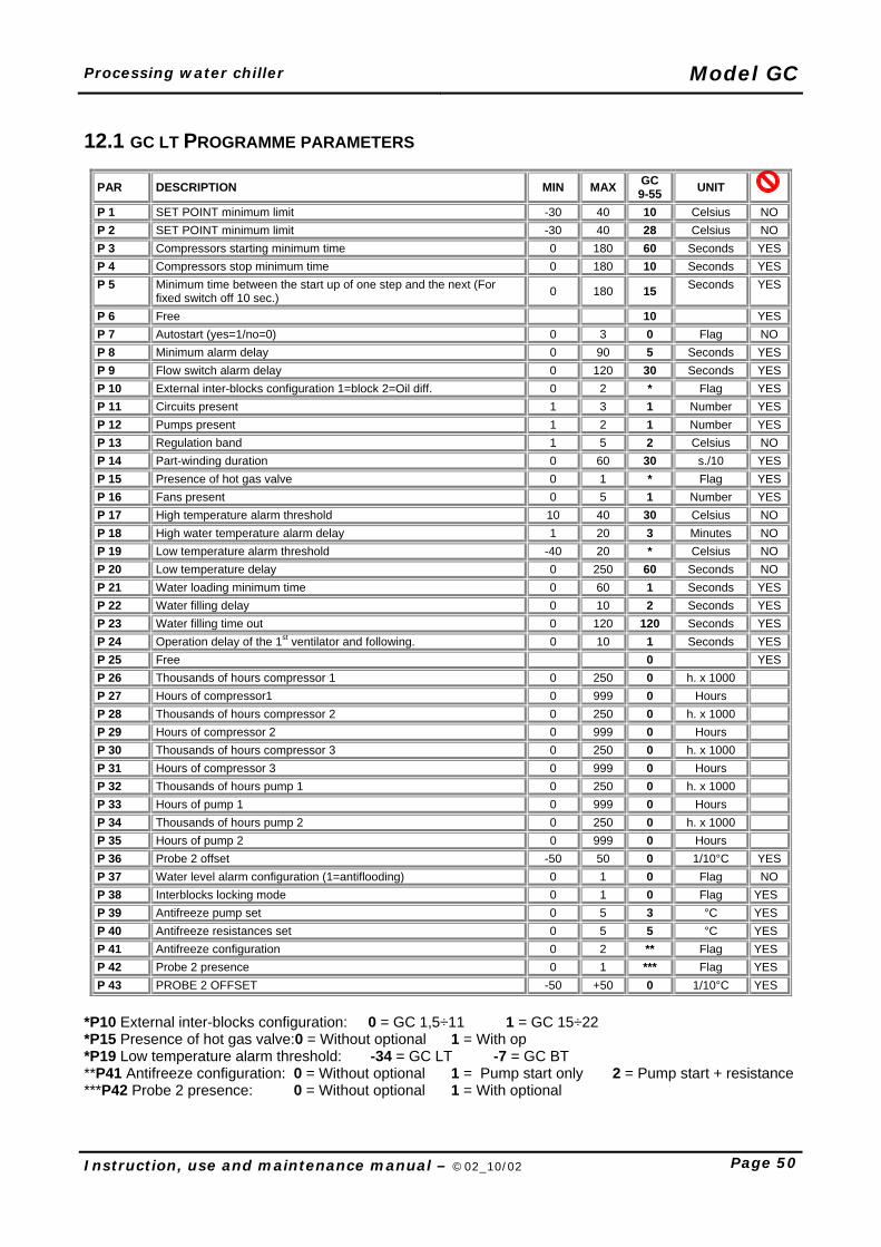
12.1 GC LT PROGRAMME PARAMETERS
PAR DESCRIPTION MIN MAX GC 9-55 UNIT
P 1 SET POINT minimum limit -30 40 10 Celsius NO P 2 SET POINT minimum limit -30 40 28 Celsius NO P 3 Compressors starting minimum time 0 180 60 Seconds YESP 4 Compressors stop minimum time 0 180 10 Seconds YESP 5 Minimum time between the start up of one step and the next (For
fixed switch off 10 sec.) 0 180 15 Seconds YES
P 6 Free 10 YESP 7 Autostart (yes=1/no=0) 0 3 0 Flag NO P 8 Minimum alarm delay 0 90 5 Seconds YESP 9 Flow switch alarm delay 0 120 30 Seconds YESP 10 External inter-blocks configuration 1=block 2=Oil diff. 0 2 * Flag YESP 11 Circuits present 1 3 1 Number YESP 12 Pumps present 1 2 1 Number YESP 13 Regulation band 1 5 2 Celsius NO P 14 Part-winding duration 0 60 30 s./10 YESP 15 Presence of hot gas valve 0 1 * Flag YESP 16 Fans present 0 5 1 Number YESP 17 High temperature alarm threshold 10 40 30 Celsius NO P 18 High water temperature alarm delay 1 20 3 Minutes NO P 19 Low temperature alarm threshold -40 20 * Celsius NO P 20 Low temperature delay 0 250 60 Seconds NO P 21 Water loading minimum time 0 60 1 Seconds YESP 22 Water filling delay 0 10 2 Seconds YESP 23 Water filling time out 0 120 120 Seconds YESP 24 Operation delay of the 1st ventilator and following. 0 10 1 Seconds YESP 25 Free 0 YESP 26 Thousands of hours compressor 1 0 250 0 h. x 1000 P 27 Hours of compressor1 0 999 0 Hours P 28 Thousands of hours compressor 2 0 250 0 h. x 1000 P 29 Hours of compressor 2 0 999 0 Hours P 30 Thousands of hours compressor 3 0 250 0 h. x 1000 P 31 Hours of compressor 3 0 999 0 Hours P 32 Thousands of hours pump 1 0 250 0 h. x 1000 P 33 Hours of pump 1 0 999 0 Hours P 34 Thousands of hours pump 2 0 250 0 h. x 1000 P 35 Hours of pump 2 0 999 0 Hours P 36 Probe 2 offset -50 50 0 1/10°C YESP 37 Water level alarm configuration (1=antiflooding) 0 1 0 Flag NO P 38 Interblocks locking mode 0 1 0 Flag YES P 39 Antifreeze pump set 0 5 3 °C YES P 40 Antifreeze resistances set 0 5 5 °C YES P 41 Antifreeze configuration 0 2 ** Flag YES P 42 Probe 2 presence 0 1 *** Flag YES P 43 PROBE 2 OFFSET -50 +50 0 1/10°C YES
*P10 External inter-blocks configuration: 0 = GC 1,5÷11 1 = GC 15÷22 *P15 Presence of hot gas valve:0 = Without optional 1 = With op *P19 Low temperature alarm threshold: -34 = GC LT -7 = GC BT **P41 Antifreeze configuration: 0 = Without optional 1 = Pump start only 2 = Pump start + resistance ***P42 Probe 2 presence: 0 = Without optional 1 = With optional
Model GC Processing water chiller
Page 51 Instruction, use and maintenance manual – ©02_10/02
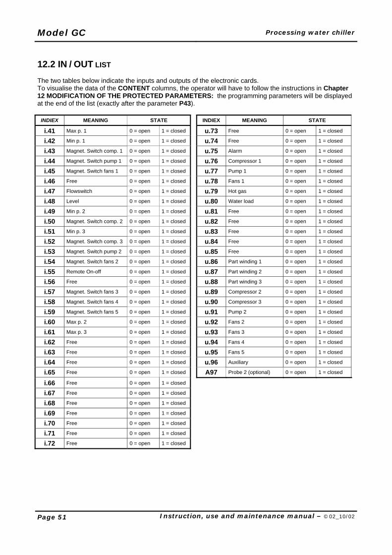
12.2 IN / OUT LIST The two tables below indicate the inputs and outputs of the electronic cards. To visualise the data of the CONTENT columns, the operator will have to follow the instructions in Chapter 12 MODIFICATION OF THE PROTECTED PARAMETERS: the programming parameters will be displayed at the end of the list (exactly after the parameter P43).
INDIEX MEANING STATE INDIEX MEANING STATE
i.41 Max p. 1 0 = open 1 = closed u.73 Free 0 = open 1 = closed
i.42 Min p. 1 0 = open 1 = closed u.74 Free 0 = open 1 = closed
i.43 Magnet. Switch comp. 1 0 = open 1 = closed u.75 Alarm 0 = open 1 = closed
i.44 Magnet. Switch pump 1 0 = open 1 = closed u.76 Compressor 1 0 = open 1 = closed
i.45 Magnet. Switch fans 1 0 = open 1 = closed u.77 Pump 1 0 = open 1 = closed
i.46 Free 0 = open 1 = closed u.78 Fans 1 0 = open 1 = closed
i.47 Flowswitch 0 = open 1 = closed u.79 Hot gas 0 = open 1 = closed
i.48 Level 0 = open 1 = closed u.80 Water load 0 = open 1 = closed
i.49 Min p. 2 0 = open 1 = closed u.81 Free 0 = open 1 = closed
i.50 Magnet. Switch comp. 2 0 = open 1 = closed u.82 Free 0 = open 1 = closed
i.51 Min p. 3 0 = open 1 = closed u.83 Free 0 = open 1 = closed
i.52 Magnet. Switch comp. 3 0 = open 1 = closed u.84 Free 0 = open 1 = closed
i.53 Magnet. Switch pump 2 0 = open 1 = closed u.85 Free 0 = open 1 = closed
i.54 Magnet. Switch fans 2 0 = open 1 = closed u.86 Part winding 1 0 = open 1 = closed
i.55 Remote On-off 0 = open 1 = closed u.87 Part winding 2 0 = open 1 = closed
i.56 Free 0 = open 1 = closed u.88 Part winding 3 0 = open 1 = closed
i.57 Magnet. Switch fans 3 0 = open 1 = closed u.89 Compressor 2 0 = open 1 = closed
i.58 Magnet. Switch fans 4 0 = open 1 = closed u.90 Compressor 3 0 = open 1 = closed
i.59 Magnet. Switch fans 5 0 = open 1 = closed u.91 Pump 2 0 = open 1 = closed
i.60 Max p. 2 0 = open 1 = closed u.92 Fans 2 0 = open 1 = closed
i.61 Max p. 3 0 = open 1 = closed u.93 Fans 3 0 = open 1 = closed
i.62 Free 0 = open 1 = closed u.94 Fans 4 0 = open 1 = closed
i.63 Free 0 = open 1 = closed u.95 Fans 5 0 = open 1 = closed
i.64 Free 0 = open 1 = closed u.96 Auxiliary 0 = open 1 = closed
i.65 Free 0 = open 1 = closed A97 Probe 2 (optional) 0 = open 1 = closed
i.66 Free 0 = open 1 = closed i.67 Free 0 = open 1 = closed i.68 Free 0 = open 1 = closed i.69 Free 0 = open 1 = closed i.70 Free 0 = open 1 = closed i.71 Free 0 = open 1 = closed i.72 Free 0 = open 1 = closed
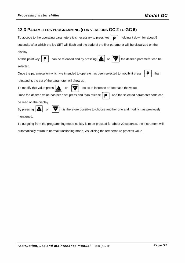
Processing water chiller Model GC
Instruction, use and maintenance manual – ©02_10/02 Page 52
12.3 PARAMETERS PROGRAMMING (FOR VERSIONS GC 2 TO GC 6) To accede to the operating parameters it is necessary to press key holding it down for about 5 seconds, after which the led SET will flash and the code of the first parameter will be visualized on the display. At this point key can be released and by pressing or the desired parameter can be selected. Once the parameter on which we intended to operate has been selected to modify it press , than released it, the set of the parameter will show up. To modify this value press or so as to increase or decrease the value. Once the desired value has been set press and than release and the selected parameter code can be read on the display. By pressing or it is therefore possible to choose another one and modify it as previously mentioned. To outgoing from the programming mode no key is to be pressed for about 20 seconds, the instrument will automatically return to normal functioning mode, visualizing the temperature process value.
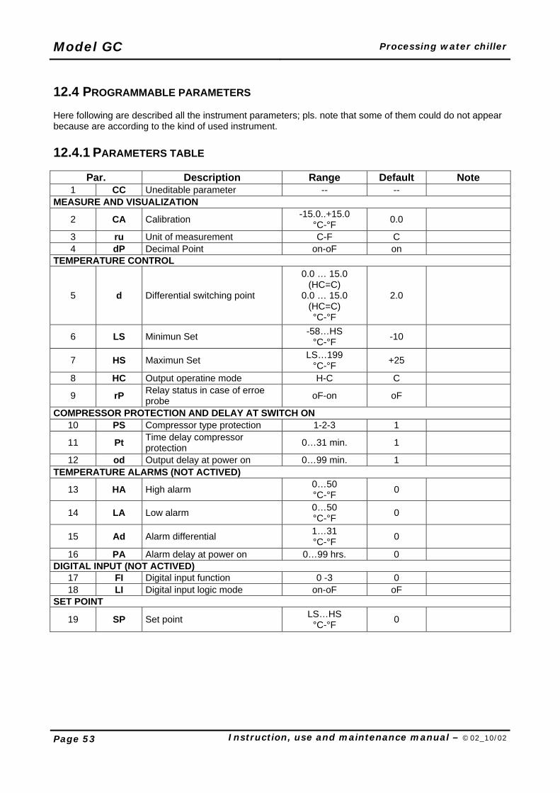
Model GC Processing water chiller
Page 53 Instruction, use and maintenance manual – ©02_10/02
12.4 PROGRAMMABLE PARAMETERS Here following are described all the instrument parameters; pls. note that some of them could do not appear because are according to the kind of used instrument. 12.4.1 PARAMETERS TABLE
Par. Description Range Default Note 1 CC Uneditable parameter -- --
MEASURE AND VISUALIZATION
2 CA Calibration -15.0..+15.0 °C-°F 0.0
3 ru Unit of measurement C-F C 4 dP Decimal Point on-oF on
TEMPERATURE CONTROL
5 d Differential switching point
0.0 … 15.0 (HC=C)
0.0 … 15.0 (HC=C) °C-°F
2.0
6 LS Minimun Set -58…HS °C-°F -10
7 HS Maximun Set LS…199 °C-°F +25
8 HC Output operatine mode H-C C
9 rP Relay status in case of erroe probe oF-on oF
COMPRESSOR PROTECTION AND DELAY AT SWITCH ON 10 PS Compressor type protection 1-2-3 1
11 Pt Time delay compressor protection 0…31 min. 1
12 od Output delay at power on 0…99 min. 1 TEMPERATURE ALARMS (NOT ACTIVED)
13 HA High alarm 0…50 °C-°F 0
14 LA Low alarm 0…50 °C-°F 0
15 Ad Alarm differential 1…31 °C-°F 0
16 PA Alarm delay at power on 0…99 hrs. 0 DIGITAL INPUT (NOT ACTIVED)
17 FI Digital input function 0 -3 0 18 LI Digital input logic mode on-oF oF
SET POINT
19 SP Set point LS…HS °C-°F 0
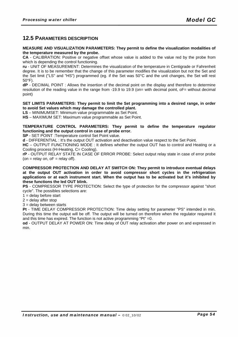
Processing water chiller Model GC
Instruction, use and maintenance manual – ©02_10/02 Page 54
12.5 PARAMETERS DESCRIPTION MEASURE AND VISUALIZATION PARAMETERS: They permit to define the visualization modalities of the temperature measured by the probe. CA - CALIBRATION: Positive or negative offset whose value is added to the value red by the probe from which is depending the control functioning. ru - UNIT OF MEASUREMENT: Determines the visualization of the temperature in Centigrade or Fahrenheit degree. It is to be remember that the change of this parameter modifies the visualization but not the Set and the Set limit ("LS" and "HS") programmed (eg. if the Set was 50°C and the unit changes, the Set will rest 50°F). dP - DECIMAL POINT : Allows the insertion of the decimal point on the display and therefore to determine resolution of the reading value in the range from -19.9 to 19.9 (on= with decimal point, oF= without decimal point) SET LIMITS PARAMETERS: They permit to limit the Set programming into a desired range, in order to avoid Set values which may damage the controlled plant. LS – MINIMUMSET: Minimum value programmable as Set Point. HS – MAXIMUM SET: Maximum value programmable as Set Point. TEMPERATURE CONTROL PARAMETERS: They permit to define the temperature regulator functioning and the output control in case of probe error. SP - SET POINT :Temperature control Set Point value. d - DIFFERENTIAL : It’s the output OUT activation and deactivation value respect to the Set Point. HC – OUTPUT FUNCTIONING MODE : It defines whether the output OUT has to control and Heating or a Cooling process (H=Heating, C= Cooling). rP - OUTPUT RELAY STATE IN CASE OF ERROR PROBE: Select output relay state in case of error probe (on = relay on, oF = relay off). COMPRESSOR PROTECTION AND DELAY AT SWITCH ON: They permit to introduce eventual delays at the output OUT activation in order to avoid compressor short cycles in the refrigeration applications or at each instrument start. When the output has to be activated but it’s inhibited by these functions the led OUT blink. PS - COMPRESSOR TYPE PROTECTION: Select the type of protection for the compressor against "short cycle". The possibles selections are: 1 = delay before start 2 = delay after stop 3 = delay between starts Pt - TIME DELAY COMPRESSOR PROTECTION: Time delay setting for parameter "PS" intended in min. During this time the output will be off. The output will be turned on therefore when the regulator required it and this time has expired. The function is not active programming “Pt” =0. od - OUTPUT DELAY AT POWER ON: Time delay of OUT relay activation after power on and expressed in min.
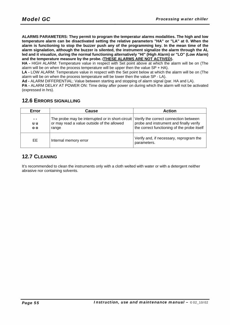
Model GC Processing water chiller
Page 55 Instruction, use and maintenance manual – ©02_10/02
ALARMS PARAMETERS: They permit to program the temperatur alarms modalities. The high and low temperature alarm can be disactivated setting the relative parameters "HA" or "LA" at 0. When the alarm is functioning to stop the buzzer push any of the programming key. In the mean time of the alarm signalation, although the buzzer is silented, the instrument signalize the alarm through the AL led and it visualize, during the normal functioning alternatively "HI" (High Alarm) or "LO" (Low Alarm) and the temperature measure by the probe. (THESE ALARMS ARE NOT ACTIVED). HA - HIGH ALARM: Temperature value in respect with Set point above at which the alarm will be on (The alarm will be on when the process temperature will be upper then the value SP + HA). LA - LOW ALARM: Temperature value in respect with the Set point below at which the alarm will be on (The alarm will be on when the process temperature will be lower then the value SP - LA). Ad - ALARM DIFFERENTIAL: Value between starting and stopping of alarm signal (par. HA and LA). PA - ALARM DELAY AT POWER ON: Time delay after power on during which the alarm will not be activated (expressed in hrs). 12.6 ERRORS SIGNALLING
Error Cause Action
- - u u o o
The probe may be interrupted or in short-circuit or may read a value outside of the allowed range
Verify the correct connection between probe and instrument and finally verify the correct functioning of the probe itself
EE Internal memory error Verify and, if necessary, reprogram the parameters.
12.7 CLEANING It’s recommended to clean the instruments only with a cloth welted with water or with a detergent neither abrasive nor containing solvents.
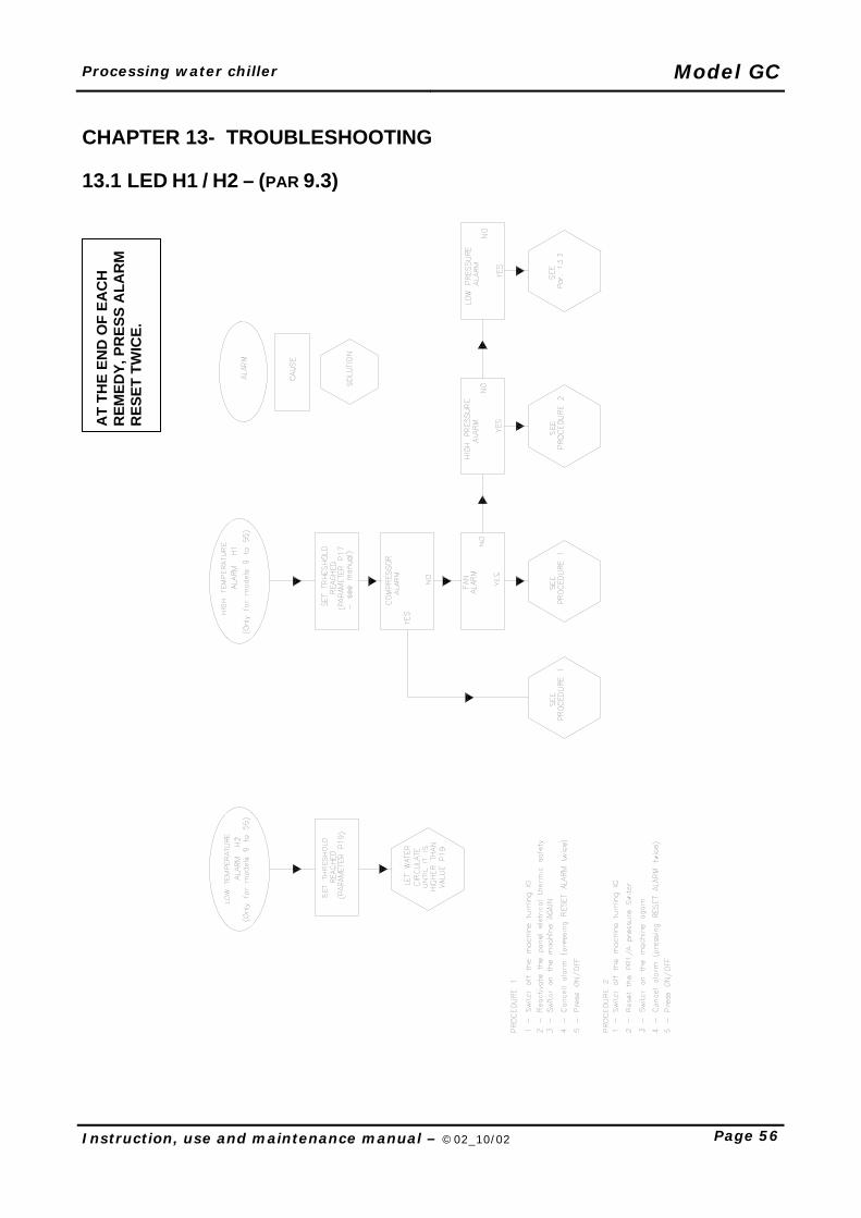
Processing water chiller Model GC
Instruction, use and maintenance manual – ©02_10/02 Page 56
CHAPTER 13- TROUBLESHOOTING 13.1 LED H1 / H2 – (PAR 9.3)
AT
THE
END
OF
EAC
H
REM
EDY,
PR
ESS
ALA
RM
R
ESET
TW
ICE.
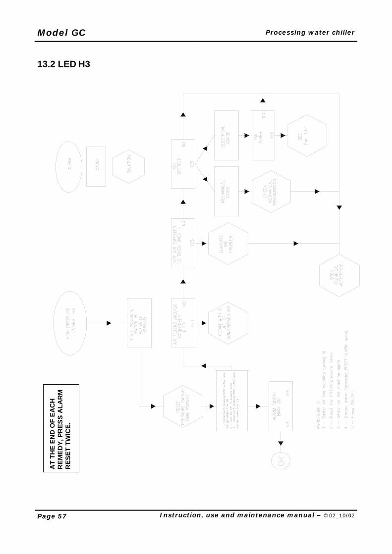
Model GC Processing water chiller
Page 57 Instruction, use and maintenance manual – ©02_10/02
13.2 LED H3
AT
THE
END
OF
EAC
H
REM
EDY,
PR
ESS
ALA
RM
R
ESET
TW
ICE.
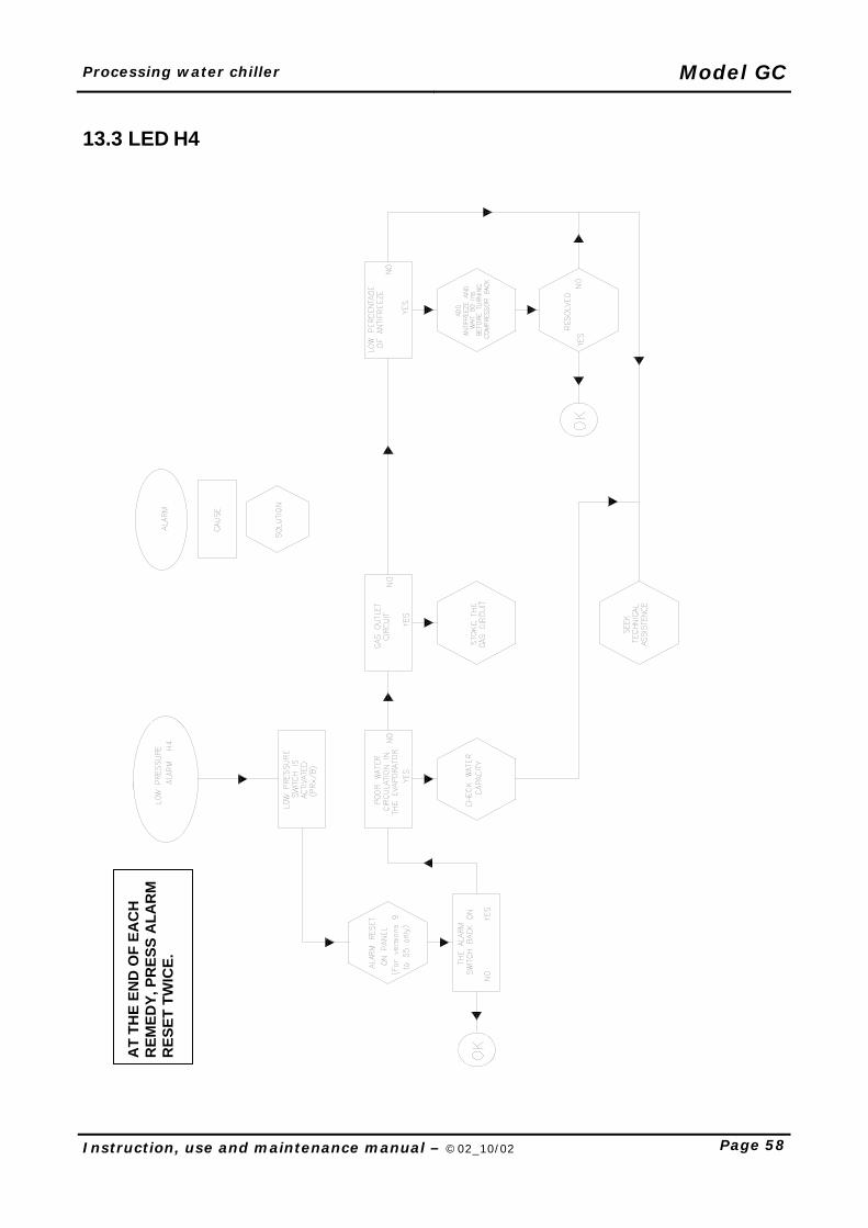
Processing water chiller Model GC
Instruction, use and maintenance manual – ©02_10/02 Page 58
13.3 LED H4
AT
THE
END
OF
EAC
H
REM
EDY,
PR
ESS
ALA
RM
R
ESET
TW
ICE.
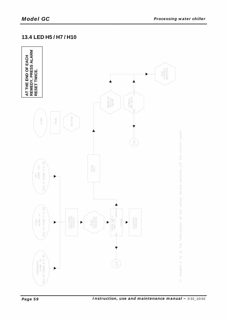
Model GC Processing water chiller
Page 59 Instruction, use and maintenance manual – ©02_10/02
13.4 LED H5 / H7 / H10
AT
THE
END
OF
EAC
H
REM
EDY,
PR
ESS
ALA
RM
R
ESET
TW
ICE.
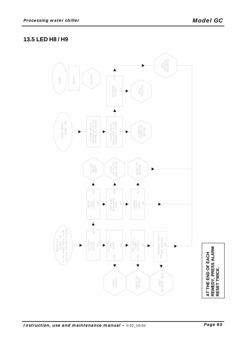
Processing water chiller Model GC
Instruction, use and maintenance manual – ©02_10/02 Page 60
13.5 LED H8 / H9
AT
THE
END
OF
EAC
H
REM
EDY,
PR
ESS
ALA
RM
R
ESET
TW
ICE.
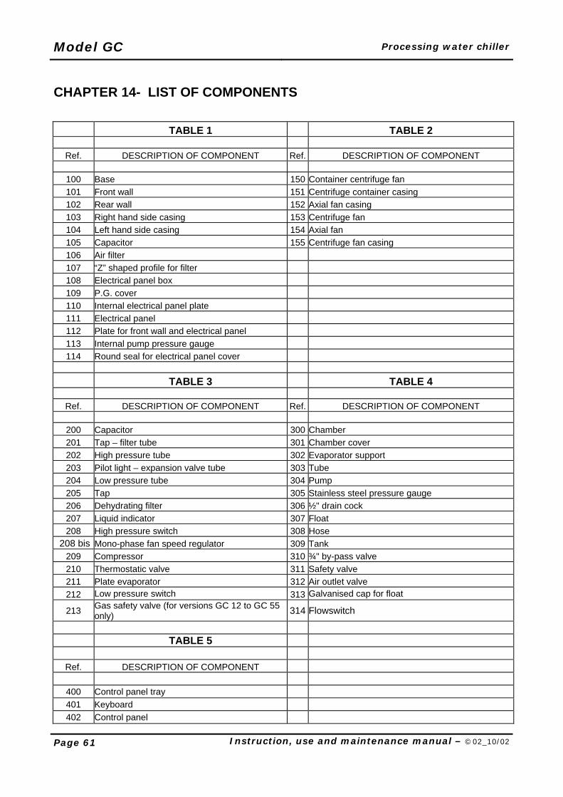
Model GC Processing water chiller
Page 61 Instruction, use and maintenance manual – ©02_10/02
CHAPTER 14- LIST OF COMPONENTS TABLE 1 TABLE 2
Ref. DESCRIPTION OF COMPONENT Ref. DESCRIPTION OF COMPONENT
100 Base 150 Container centrifuge fan 101 Front wall 151 Centrifuge container casing 102 Rear wall 152 Axial fan casing 103 Right hand side casing 153 Centrifuge fan 104 Left hand side casing 154 Axial fan 105 Capacitor 155 Centrifuge fan casing 106 Air filter 107 “Z” shaped profile for filter 108 Electrical panel box 109 P.G. cover 110 Internal electrical panel plate 111 Electrical panel 112 Plate for front wall and electrical panel 113 Internal pump pressure gauge 114 Round seal for electrical panel cover
TABLE 3 TABLE 4
Ref. DESCRIPTION OF COMPONENT Ref. DESCRIPTION OF COMPONENT
200 Capacitor 300 Chamber 201 Tap – filter tube 301 Chamber cover 202 High pressure tube 302 Evaporator support 203 Pilot light – expansion valve tube 303 Tube 204 Low pressure tube 304 Pump 205 Tap 305 Stainless steel pressure gauge 206 Dehydrating filter 306 ½" drain cock 207 Liquid indicator 307 Float 208 High pressure switch 308 Hose
208 bis Mono-phase fan speed regulator 309 Tank 209 Compressor 310 ¾" by-pass valve 210 Thermostatic valve 311 Safety valve 211 Plate evaporator 312 Air outlet valve 212 Low pressure switch 313 Galvanised cap for float
213 Gas safety valve (for versions GC 12 to GC 55 only) 314 Flowswitch
TABLE 5
Ref. DESCRIPTION OF COMPONENT
400 Control panel tray 401 Keyboard 402 Control panel

Processing water chiller Model GC
Instruction, use and maintenance manual – ©02_10/02 Page 62
TABLE 1: GC 2 – 4 REVISION 00
TABLE 1: GC 6 – 18 REVISION 00
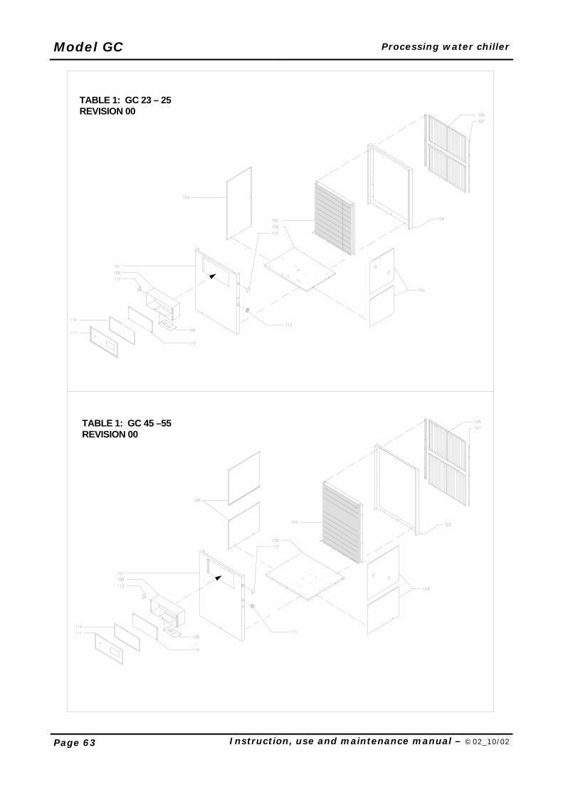
Model GC Processing water chiller
Page 63 Instruction, use and maintenance manual – ©02_10/02
TABLE 1: GC 23 – 25 REVISION 00
TABLE 1: GC 45 –55 REVISION 00
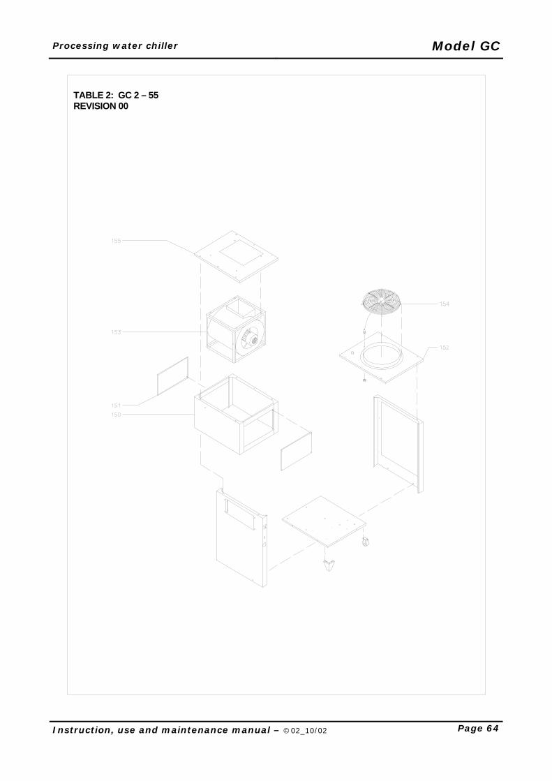
Processing water chiller Model GC
Instruction, use and maintenance manual – ©02_10/02 Page 64
TABLE 2: GC 2 – 55 REVISION 00
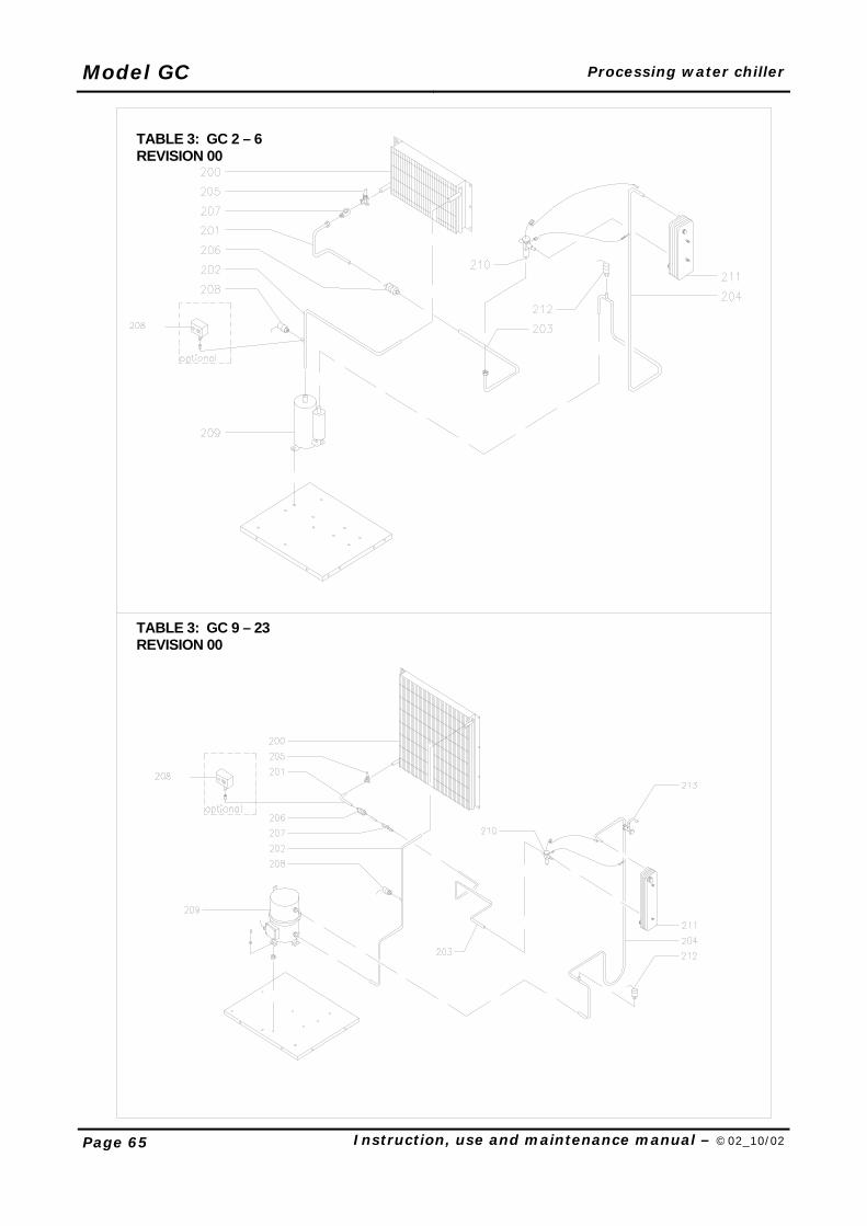
Model GC Processing water chiller
Page 65 Instruction, use and maintenance manual – ©02_10/02
TABLE 3: GC 2 – 6 REVISION 00
TABLE 3: GC 9 – 23 REVISION 00
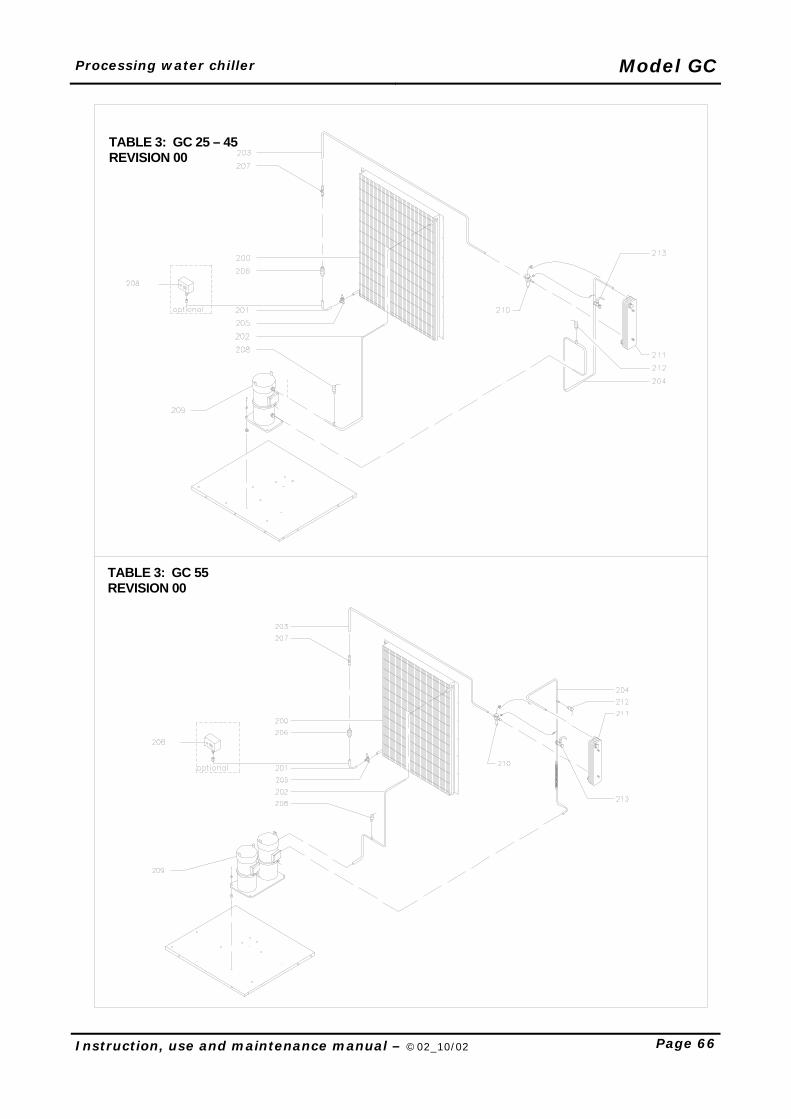
Processing water chiller Model GC
Instruction, use and maintenance manual – ©02_10/02 Page 66
TABLE 3: GC 25 – 45 REVISION 00
TABLE 3: GC 55 REVISION 00
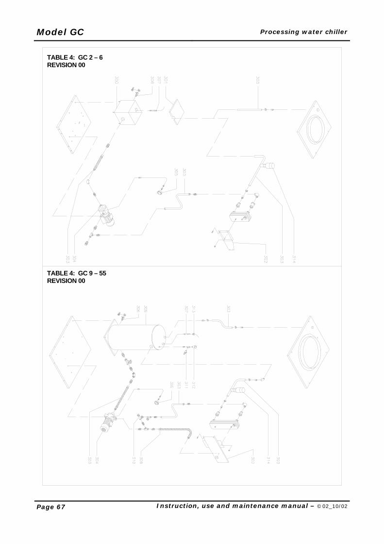
Model GC Processing water chiller
Page 67 Instruction, use and maintenance manual – ©02_10/02
TABLE 4: GC 2 – 6 REVISION 00
TABLE 4: GC 9 – 55 REVISION 00
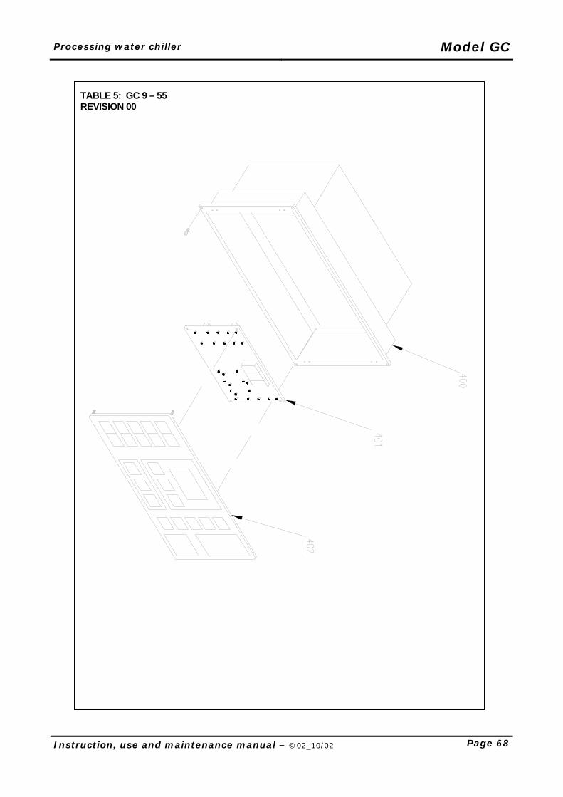
Processing water chiller Model GC
Instruction, use and maintenance manual – ©02_10/02 Page 68
TABLE 5: GC 9 – 55 REVISION 00
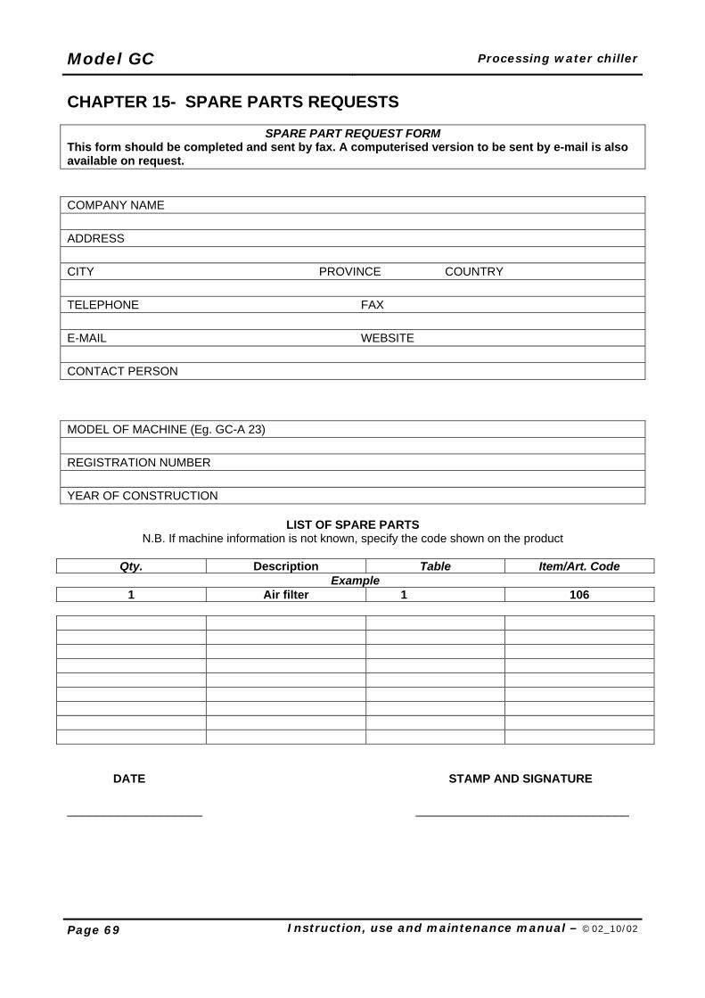
Model GC Processing water chiller
Page 69 Instruction, use and maintenance manual – ©02_10/02
CHAPTER 15- SPARE PARTS REQUESTS
SPARE PART REQUEST FORM This form should be completed and sent by fax. A computerised version to be sent by e-mail is also available on request. COMPANY NAME ADDRESS CITY PROVINCE COUNTRY TELEPHONE FAX E-MAIL WEBSITE CONTACT PERSON MODEL OF MACHINE (Eg. GC-A 23) REGISTRATION NUMBER YEAR OF CONSTRUCTION
LIST OF SPARE PARTS N.B. If machine information is not known, specify the code shown on the product
Qty. Description Table Item/Art. Code
Example 1 Air filter 1 106
DATE STAMP AND SIGNATURE ___________________ ______________________________
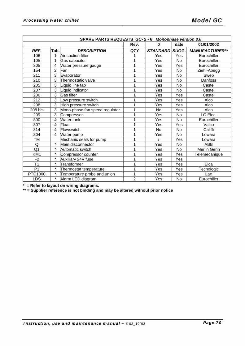
Processing water chiller Model GC
Instruction, use and maintenance manual – ©02_10/02 Page 70
SPARE PARTS REQUESTS GC- 2 - 6 Monophase version 3.0 Rev. 0 date 01/01/2002
REF. Tab. DESCRIPTION QTY STANDARD SUGG. MANUFACTURER** 106 1 Air suction filter 1 Yes Yes Eurochiller 105 1 Gas capacitor 1 Yes No Eurochiller 305 4 Water pressure gauge 1 Yes Yes Eurochiller 154 2 Fan 1 Yes No Ziehl-Abegg 211 3 Evaporator 1 Yes No Swep 210 3 Thermostatic valve 1 Yes No Danfoss 205 3 Liquid line tap 1 Yes No Castel 207 3 Liquid indicator 1 Yes No Castel 206 3 Gas filter 1 Yes Yes Castel 212 3 Low pressure switch 1 Yes Yes Alco 208 3 High pressure switch 1 Yes Yes Alco
208 bis 3 Mono-phase fan speed regulator 1 No Yes Alco 209 3 Compressor 1 Yes No LG Elec. 300 4 Water tank 1 Yes No Eurochiller 307 4 Float 1 Yes Yes Valco 314 4 Flowswitch 1 No No Califfi 304 4 Water pump 1 Yes No Lowara TM Mechanic seals for pump 1 / Yes Lowara Q * Main disconnector 1 Yes No ABB
Q1 * Automatic switch 1 Yes No Merlin Gerin KM1 * Compressor counter 1 Yes Yes Telemecanique F2 * Auxiliary 24V fuse 1 Yes Yes T1 * Transformer 1 Yes Yes Elca P1 * Thermostat temperature 1 Yes Yes Tecnologic
PTC1000 * Temperature probe and union 1 Yes Yes Lae LDS * Alarm LED diagram 2 Yes No Eurochiller
* = Refer to layout on wiring diagrams. ** = Supplier reference is not binding and may be altered without prior notice
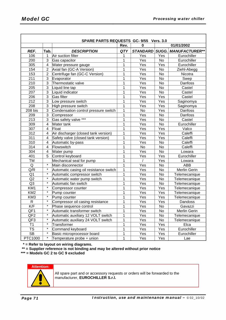
Model GC Processing water chiller
Page 71 Instruction, use and maintenance manual – ©02_10/02
SPARE PARTS REQUESTS GC- 9/55 Vers. 3.0 Rev. 0 01/01/2002
REF. Tab. DESCRIPTION QTY STANDARD SUGG. MANUFACTURER**106 1 Air suction filter 1 Yes Yes Eurochiller 200 3 Gas capacitor 1 Yes No Eurochiller 305 4 Water pressure gauge 1 Yes Yes Eurochiller 154 2 Axial fan (GC-A Version) 1 Yes No Ziehl-Abegg 153 2 Centrifuge fan (GC-C Version) 1 Yes No Nicotra 211 3 Evaporator 1 Yes No Swep 210 3 Thermostatic valve 1 Yes No Danfoss 205 3 Liquid line tap 1 Yes No Castel 207 3 Liquid indicator 1 Yes No Castel 206 3 Gas filter 1 Yes Yes Castel 212 3 Low pressure switch 1 Yes Yes Saginomya 208 3 High pressure switch 1 Yes Yes Saginomya
208 bis 3 Condensation control pressure switch 1 No Yes Danfoss 209 3 Compressor 1 Yes No Danfoss 213 3 Gas safety valve *** 1 Yes No Castel 309 4 Water tank 1 Yes No Eurochiller 307 4 Float 1 Yes Yes Valco 312 4 Air discharger (closed tank version) 1 Yes Yes Caleffi 311 4 Safety valve (closed tank version) 1 Yes Yes Caleffi 310 4 Automatic by-pass 1 Yes No Caleffi 314 4 Flowswitch 1 No No Caleffi 304 4 Water pump 1 Yes No Lowara 401 5 Control keyboard 1 Yes Yes Eurochiller TM Mechanical seal for pump 1 / Yes Lowara Q * Main disconnector 1 Yes No ABB
Q/R * Automatic casing oil resistance switch 1 Yes No Merlin Gerin Q1 * Automatic compressor switch 1 Yes No Telemecanique Q2 * Automatic water pump switch 1 Yes No Telemecanique Q3 * Automatic fan switch 1 Yes No Telemecanique
KM1 * Compressor counter 1 Yes Yes Telemecanique KM2 * Pump counter 1 Yes Yes Telemecanique KM3 * Pump counter 1 Yes Yes Telemecanique
R * Compressor oil casing resistance 1 Yes Yes Dandoss K/F * Phase sequence control 1 Yes No Gavazzi QF1 * Automatic transformer switch 1 Yes No Merlin Gerin QF2 * Automatic auxiliary 12 VOLT switch 1 Yes No Telemecanique QF3 * Automatic auxiliary 24 VOLT switch 1 Yes No Telemecanique T1 * Transformer 1 Yes Yes Elca TS * Command keyboard 1 Yes Yes Eurochiller SB * Basic microprocessor board 1 Yes Yes Eurochiller
PTC1000 * Temperature probe + union 1 Yes Yes Lae * = Refer to layout on wiring diagrams. ** = Supplier reference is not binding and may be altered without prior notice *** = Models GC 2 to GC 9 excluded
Attention:
All spare part and or accessory requests or orders will be forwarded to the manufacturer, EUROCHILLER S.r.l.
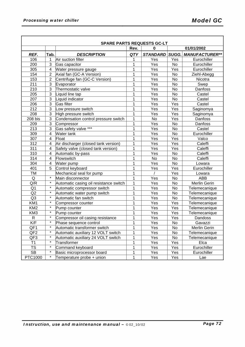
Processing water chiller Model GC
Instruction, use and maintenance manual – ©02_10/02 Page 72
SPARE PARTS REQUESTS GC-LT Rev. 0 01/01/2002
REF. Tab. DESCRIPTION QTY STANDARD SUGG. MANUFACTURER**106 1 Air suction filter 1 Yes Yes Eurochiller 200 3 Gas capacitor 1 Yes No Eurochiller 305 4 Water pressure gauge 1 Yes Yes Eurochiller 154 2 Axial fan (GC-A Version) 1 Yes No Ziehl-Abegg 153 2 Centrifuge fan (GC-C Version) 1 Yes No Nicotra 211 3 Evaporator 1 Yes No Swep 210 3 Thermostatic valve 1 Yes No Danfoss 205 3 Liquid line tap 1 Yes No Castel 207 3 Liquid indicator 1 Yes No Castel 206 3 Gas filter 1 Yes Yes Castel 212 3 Low pressure switch 1 Yes Yes Saginomya 208 3 High pressure switch 1 Yes Yes Saginomya
208 bis 3 Condensation control pressure switch 1 No Yes Danfoss 209 3 Compressor 1 Yes No Danfoss 213 3 Gas safety valve *** 1 Yes No Castel 309 4 Water tank 1 Yes No Eurochiller 307 4 Float 1 Yes Yes Valco 312 4 Air discharger (closed tank version) 1 Yes Yes Caleffi 311 4 Safety valve (closed tank version) 1 Yes Yes Caleffi 310 4 Automatic by-pass 1 Yes No Caleffi 314 4 Flowswitch 1 No No Caleffi 304 4 Water pump 1 Yes No Lowara 401 5 Control keyboard 1 Yes Yes Eurochiller TM Mechanical seal for pump 1 / Yes Lowara Q * Main disconnector 1 Yes No ABB
Q/R * Automatic casing oil resistance switch 1 Yes No Merlin Gerin Q1 * Automatic compressor switch 1 Yes No Telemecanique Q2 * Automatic water pump switch 1 Yes No Telemecanique Q3 * Automatic fan switch 1 Yes No Telemecanique
KM1 * Compressor counter 1 Yes Yes Telemecanique KM2 * Pump counter 1 Yes Yes Telemecanique KM3 * Pump counter 1 Yes Yes Telemecanique
R * Compressor oil casing resistance 1 Yes Yes Dandoss K/F * Phase sequence control 1 Yes No Gavazzi QF1 * Automatic transformer switch 1 Yes No Merlin Gerin QF2 * Automatic auxiliary 12 VOLT switch 1 Yes No Telemecanique QF3 * Automatic auxiliary 24 VOLT switch 1 Yes No Telemecanique T1 * Transformer 1 Yes Yes Elca TS * Command keyboard 1 Yes Yes Eurochiller SB * Basic microprocessor board 1 Yes Yes Eurochiller
PTC1000 * Temperature probe + union 1 Yes Yes Lae
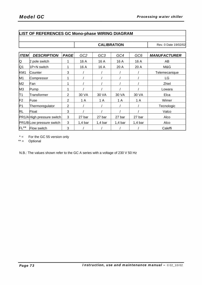
Model GC Processing water chiller
Page 73 Instruction, use and maintenance manual – ©02_10/02
LIST OF REFERENCES GC Mono-phase WIRING DIAGRAM
CALIBRATION Rev. 0 Date 19/02/02
ITEM DESCRIPTION PAGE GC2 GC3 GC4 GC6 MANUFACTURER
Q 2 pole switch 1 16 A 16 A 16 A 16 A AB Q1 1P+N switch 1 16 A 16 A 20 A 20 A M&G KM1 Counter 3 / / / / Telemecanique M1 Compressor 1 / / / / LG M2 Fan 1 / / / / Zhiel M3 Pump 1 / / / / Lowara T1 Transformer 2 30 VA 30 VA 30 VA 30 VA Elca F2 Fuse 2 1 A 1 A 1 A 1 A Wimer P1 Thermoregulator 2 / / / / Tecnologic RL Float 3 / / / / Valco PR1/A High pressure switch 3 27 bar 27 bar 27 bar 27 bar Alco PR1/B Low pressure switch 3 1,4 bar 1,4 bar 1,4 bar 1,4 bar Alco FL** Flow switch 3 / / / / Caleffi
* = For the GC 55 version only ** = Optional
N.B.: The values shown refer to the GC A series with a voltage of 230 V 50 Hz
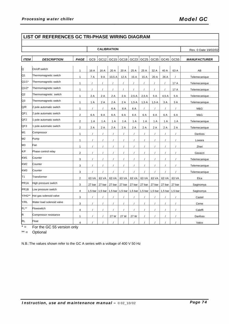
Processing water chiller Model GC
Instruction, use and maintenance manual – ©02_10/02 Page 74
Q On/off switch 1 16 A 16 A 20 A 20 A 25 A 25 A 32 A 40 A 63 A AB
Q1 Thermomagnetic switch 1 7 A 9 A 10,5 A 12 A 15 A 15 A 20 A 26 A / Telemecanique
Q1/1* Thermomagnetic switch 1 / / / / / / / / 17 A Telemecanique
Q1/2* Thermomagnetic switch 1 / / / / / / / / 17 A Telemecanique
Q2 Thermomagnetic switch 1 2 A 2 A 2 A 2 A 2,5 A 2,5 A 5 A 4,5 A 5 A Telemecanique
Q3 Thermomagnetic switch 1 1 A 2 A 2 A 2 A 1,5 A 1,5 A 1,5 A 3 A 3 A Telemecanique
Q/R 2 pole automatic switch 1 / / 6 A 6 A 6 A / / / / M&G
QF1 2 pole automatic switch 2 6 A 6 A 6 A 6 A 6 A 6 A 6 A 6 A 6 A M&G
QF2 1 pole automatic switch 2 1 A 1 A 1 A 1 A 1 A 1 A 1 A 1 A 1 A Telemecanique
QF3 1 pole automatic switch 2 2 A 2 A 2 A 2 A 2 A 2 A 2 A 2 A 2 A Telemecanique
M1 Compressor 1 / / / / / / / / / Danfoss
M2 Pump 1 / / / / / / / / / Lowara
M3 Fan 1 / / / / / / / / / Zhiel
K/F Phase control relay 2 / / / / / / / / / Gavazzi
KM1 Counter 3 / / / / / / / / / Telemecanique
KM2 Counter 3 / / / / / / / / / Telemecanique
KM3 Counter 3 / / / / / / / / / Telemecanique
T1 Transformer 2 63 VA 63 VA 63 VA 63 VA 63 VA 63 VA 63 VA 63 VA 63 VA Elca
PR1A High pressure switch 3 27 bar 27 bar 27 bar 27 bar 27 bar 27 bar 27 bar 27 bar 27 bar Saginomya
PR1B Low pressure switch 4 1,5 bar 1,5 bar 1,5 bar 1,5 bar 1,5 bar 1,5 bar 1,5 bar 1,5 bar 1,5 bar Saginomya
Y/HG** Hot gas solenoid valve 3 / / / / / / / / / Castel
Y/RL Water load solenoid valve 3 / / / / / / / / / Ceme
FL** Flowswitch 4 / / / / / / / / / Caleffi
R Compressor resistance 1 / / 27 W 27 W 27 W / / / / Danfoss
RL Float 4 / / / / / / / / / Valco
* = For the GC 55 version only ** = Optional
N.B.:The values shown refer to the GC A series with a voltage of 400 V 50 Hz
LIST OF REFERENCES GC TRI-PHASE WIRING DIAGRAM
CALIBRATION Rev. 0 Date 19/02/02
ITEM DESCRIPTION PAGE GC9 GC12 GC15 GC18 GC23 GC25 GC35 GC45 GC55 MANUFACTURER
Model GC Processing water chiller
Page 75 Instruction, use and maintenance manual – ©02_10/02
CHAPTER 16- MACHINE DEMOLITION Whenever and for whatever reason the machine needs to be eliminated and demolished all machine components must be dismantled separately and certain basic rules must be observed to protect public health and the environment. 1. All sheathes, flexible hosing and plastic components, or non-metal parts must be dismantled and
grouped according to material type. This way wherever possible, materials can be melted down for recycling.
2. The machine body and all metallic parts must be dismantled and grouped according to metal type. This way they can be melted down and recycled.
3. The exhausted gas will have to be collected separately from any other waste material not to damage the
environment; once collected it will have to be eliminated by a specialised company in compliance with the Regulations in force in the country where the machine is installed.
4. The motor oil must be collected and eliminated separately. All rights reserved. Reproduction of this manual in any form, even partial is strictly prohibited, including printing, photocopying, microfilming or other means, as well as computer processing, or copying using electronic means.

EUROCHILLER S.r.l.
INTERNATIONAL COOLING Via Milano, 69 27030 CASTELLO D’AGOGNA (PV) ITALIA
TEL. 0384-298985 - FAX 0384-298984 SERVICE 0384-298981
e-mail [email protected]