Embed Size (px)
Citation preview
EUROFLAMEKitchen/Utility and Boiler House Models
50/70, 50/90, 90/120 andKitchen/Utility System Models
50/90, 90/120
INSTALLATION AND SERVICINGMANUAL
Floor Standing Oil Boilers
providing
Central Heating and Domestic Hot Water
Models for use with
Kerosene or Gas oil
Complies with the EC Low voltage, Electromagnetic compatibility and Boiler Efficiency Directives
It is important that the boiler is installed and serviced
as described in these instructions
After installing the boiler leave these instructions with the User
GRANT ENGINEERING (IRELAND) LTD., CRINKLE, BIRR, CO. OFFALY.
Telephone: (057) 9120352/9120089
Email: [email protected]
DOC. 022 REV: 9 SEPT. '04
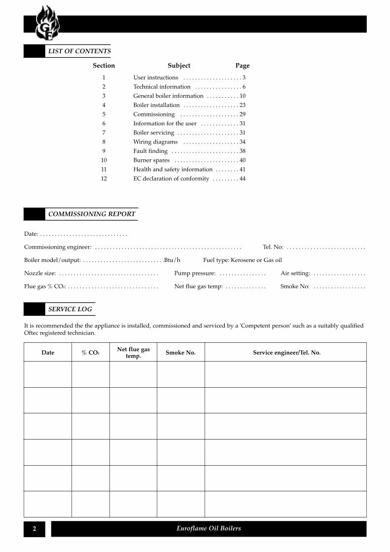
Section Subject Page1 User instructions . . . . . . . . . . . . . . . . . . . . 32 Technical information . . . . . . . . . . . . . . . . 63 General boiler information . . . . . . . . . . . 104 Boiler installation . . . . . . . . . . . . . . . . . . . 235 Commissioning . . . . . . . . . . . . . . . . . . . . 296 Information for the user . . . . . . . . . . . . . 317 Boiler servicing . . . . . . . . . . . . . . . . . . . . . 318 Wiring diagrams . . . . . . . . . . . . . . . . . . . 349 Fault finding . . . . . . . . . . . . . . . . . . . . . . . 3810 Burner spares . . . . . . . . . . . . . . . . . . . . . . 4011 Health and safety information . . . . . . . . 4112 EC declaration of conformity . . . . . . . . . 44
2 Euroflame Oil Boilers
LIST OF CONTENTS
COMMISSIONING REPORT
SERVICE LOG
Date: . . . . . . . . . . . . . . . . . . . . . . . . . . . . . .
Commissioning engineer: . . . . . . . . . . . . . . . . . . . . . . . . . . . . . . . . . . . . . . . . . . . . . . . . . . Tel. No: . . . . . . . . . . . . . . . . . . . . . . . . . . .
Boiler model/output: . . . . . . . . . . . . . . . . . . . . . . . . . . . .Btu/h Fuel type: Kerosene or Gas oil
Nozzle size: . . . . . . . . . . . . . . . . . . . . . . . . . . . . . . . . . . Pump pressure: . . . . . . . . . . . . . . . . Air setting: . . . . . . . . . . . . . . . . . .
Flue gas % CO2: . . . . . . . . . . . . . . . . . . . . . . . . . . . . . . . Net flue gas temp: . . . . . . . . . . . . . . Smoke No: . . . . . . . . . . . . . . . . . .
It is recommended the the appliance is installed, commissioned and serviced by a 'Competent person' such as a suitably qualifiedOftec registered technician.
Net flue gasDate % CO2 Smoke No. Service engineer/Tel. No.temp.
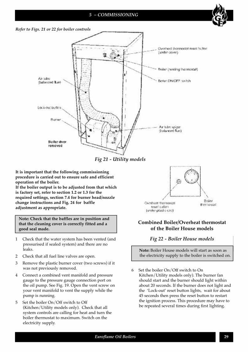
The boiler will provide domestic hot water and centralheating and is fully automatic once switched on. AnOn/Off switch, (except 50/70) see Fig. A, is fitted to theEuroflame Kitchen/Utility model, which lights when theboiler is switched on, but does not necessarily indicatethe burner is firing.
To access the Kitchen/Utility model controls, pull thefront panel off (push-on fixings).
1. Ensure that - There is sufficient fuel, of the correcttype, in the supply tank and all fuel supply valvesare open. The water supply is on. The electricitysupply to the boiler is off. The boiler On/Off switch(if fitted) is set to OFF (Kitchen/Utility models, theneon in the switch is not alight). The roomthermostat (if fitted) is at the desired setting. Theboiler thermostat is set to the required setting (seesection 1.7).
2. Switch on the electricity supply to the boiler.
3. Standard Control PanelFor Kitchen/Utility models, set the On/Off switch toON. A neon in the switch lights when it is in the onposition.The boiler will not light automatically.
4. Timer control panel (50/90 & 90/120 Indoor only)Description and setting (see diagram below)The 24 hr. timer dial has a number of tappets aroundits edge, each corresponding to 15 minutes. Whentappets (or groups) are moved in towards the centreof the dial, the timer will be in an 'on' positionduring that period and the boiler will operate.A typical timer setting for a working family could beas follows:The groups of tappets between 6.00 and 8.00, and16.00 and 22.00 set towards the centre as shown inDiagram below. This would provide two ‘on’periods for central heating from 6 a.m. to 8 a.m.,then again from 4 p.m. to 10 p.m.To set the timer to the correct time of day, turnthe dial (outer tappet ring) clockwise until the timeof day is against the time indicator arrow head. The
diagram showsthe timer atmidnight (24.00).
IMPORTANT:Do not turn thedial anti-clockwise.
1 – USER INSTRUCTIONS
3Euroflame Oil Boilers
1.1 About your boiler
1.2 Boiler controls (see Fig. A or B)
1.3 Lighting your boiler (see Fig. A or B)
Note: Boiler House models will light at this stage.
Timer Setting
Tappets
TimeIndicator
Controls for Euroflame Kitchen/Utility models - Fig. A(Model shown without timer)
Controls for Boiler House models – Fig. B
(if fitted)
Kitchen/Utility models for short periods - Set theOn/Off to OFF.To restart, simply set the switch to ON.Kitchen/Utility models for long periods: Set theOn/Off switch to OFF and switch off the electricitysupply to the boiler. If required, the fuel supply valvemay be closed and the water and electricity suppliesturned off at the mains. To restart, refer to the fulllighting instructions above.Boiler House models for short periods - Switch offthe electricity supply to the boiler.To restart, switch on the electricity supply to theboiler.Boiler House models for long periods - Switch offthe electricity supply to the boiler. If required the fuelsupply valve may be closed and the water andelectricity supplies turned off at the mains.To restart, refer to the full lighting instructions givenpreviously.
1 Check that the boiler On/Off switch (if fitted) isON.
2 Check that any remote programmer (if fitted) isworking and is in an 'on' period.
3 Check that all thermostats are set to the desiredsetting and are calling for heat.
4 Check if the burner 'Lock-out' reset button is lit. Ifit is, press it to start the burner. If the burner failsto light and goes to 'Lock-out' again, check thatyou have sufficient fuel in the storage tank andthat the fuel supply valve is open.
5 Ensure that a fuse has not blown or that theelectricity supply has not failed.
6 Check to see if the safety thermostat has operated(see section 1.7).
If the burner still fails to light after carrying out thesechecks then a fault exists. Switch off the electricitysupply to the boiler and contact your ServiceEngineer.
Euroflame boilers will operate on either Class C2Kerosene or Class D Gas Oil. Your Installer will haveinformed you of the type of fuel your boiler has beenset to use and he will have marked this on the boilerdata label. You should always quote the type of fuelyou require when ordering from your supplier.
Do not wait until the fuel runs out before you ordersome more. Sludge in the bottom of the tank may bedrawn into the fuel lines. If it is possible, switch offthe boiler when the new supply is delivered and leavethe fuel to settle for an hour before restarting theboiler.
1 Boiler thermostat - This control allows thetemperature of the water leaving the boiler to heatthe radiators and domestic hot water to beadjusted.
The boiler thermostat has an operating range of65 to 85˚C. The following settings arerecommended:-a Heating and hot water in Winter 85˚Cb Hot water only in Summer 65˚C
2 Burner Lock-out reset button - If there is a burnermalfunction, a built-in safety circuit switches theburner off and the Lock-out reset button will light.Usually such malfunctions are short lived andpressing the reset button will restore normaloperation.If the burner continually goes to 'Lock-out' a faultexists or the fuel supply is low. If you havesufficient fuel, you will need to call your ServiceEngineer.
3 Safety thermostat - Your boiler is fitted with asafety overheat thermostat which willautomatically switch off the boiler in the case of acontrol malfunction causing overheating.If your boiler goes off and you try to light it butnothing happens and the 'lock-out' reset button onthe burner is not lit, the overhead thermostat hasprobably operated. The boiler will not light untilthe thermostat is reset. To reset, unscrew the smallplastic cap (see Fig. a or b), press the button thenreplace the cap.If this condition continually repeats, contact yourService Engineer.
1 – USER INSTRUCTIONS
4 Euroflame Oil Boilers
1.4 Turning off your boiler (see Fig. A or B)
1.7 General notes and care of your system
1.5 Points to check if burner fails to light
1.6 About your fuel
Note: Balanced flue models (flue terminal throughthe wall) must only be used with Kerosene).
Note: If you have a cylinder thermostat on your hotwater cylinder, this will control the temperature ofyour domestic hot water. The boiler thermostat settingmust be equal to or above the cylinder thermostatsetting to enable the cylinder thermostat to control thedomestic hot water system.
4 Ventilation - Always ensure that the boiler hasadequate ventilation. Any ventilation openingsprovided by the Installer must not be obstructed.Periodically check that they are clear.Do not attempt to 'box in' the boiler or build acompartment around it before consulting yourInstaller.Do not place any combustible material around oron the boiler or flue pipe.
5 Flue terminal - The flue terminal on the outsidewall must not be obstructed or damaged.In severe conditions check that the terminal doesnot become blocked by snow.
6 Frost protection - Your Installer may have fitted afrost thermostat. If not, and you are likely to beaway for a short time, leave the boiler on with theboiler thermostat set at a low setting. For longerperiods the boiler and system should be drained.Contact your Service Engineer for draining andfilling the system.
7 Cleaning and servicing - Lightly wipe over thecase with a damp cloth and a little detergent. Donot use abrasive pads or cleaners.You should have your boiler serviced at least oncea year to ensure safe and efficient operation.Contact your Service Engineer for further details.
8 Failure of electricity supply - If the electricitysupply fails, the boiler will not operate. It shouldrelight automatically when the supply is restored.
The boiler requires a 230/240 V ~ 50 Hz supply. Itmust be protected by a 5 Amp fuse.
If your boiler is operating on a sealed heating system,the installer will have pressurised the system andshould have told you (or set it on the pressure gauge)the system pressure when cold (this is normallybetween 0.8 and 1.0 bar, which will increase slightlywhen hot). If the pressure (when cold) is below the setpressure mentioned above, you should contact yourInstaller or Service Engineer to re-pressurise thesystem. If the system requires frequent re-pressuring,ask your Installer or Service Engineer to check theheating system for leaks.The boiler or system will be fitted with an automaticair vent to remove air from the system. Any airtrapped in the radiators should be removed byventing the radiators using the vent screw at the topof each radiator. Only vent a radiator if the top is cooland the bottom is hot.Excessive venting will reduce the system pressure, soonly vent when necessary and check the systempressure as mentioned above. Re-pressurise thesystem if necessary.
The boiler or system will be fitted with a safety valveto release excess pressure from the system. If water orsteam is emitted from the end of the safety valvedischarge pipe, switch off the boiler and contact yourInstaller or Service Engineer.
1 – USER INSTRUCTIONS
5Euroflame Oil Boilers
1.8 Electricity supply
Warning: This appliance must be earthed.
1.9 Sealed central heating system
Note: Your system may incorporate a 'Top-Up' vessel,advice on how to use it should be obtained from yourinstaller.
The expansion vessel air charge must be checkedannually. Failure to maintain an adequate aircharge in the vessel may invalidate the warranty.
2 – BOILER TECHNICAL INFORMATION
6
2.1
Euroflame Oil Boilers
Boiler technical data
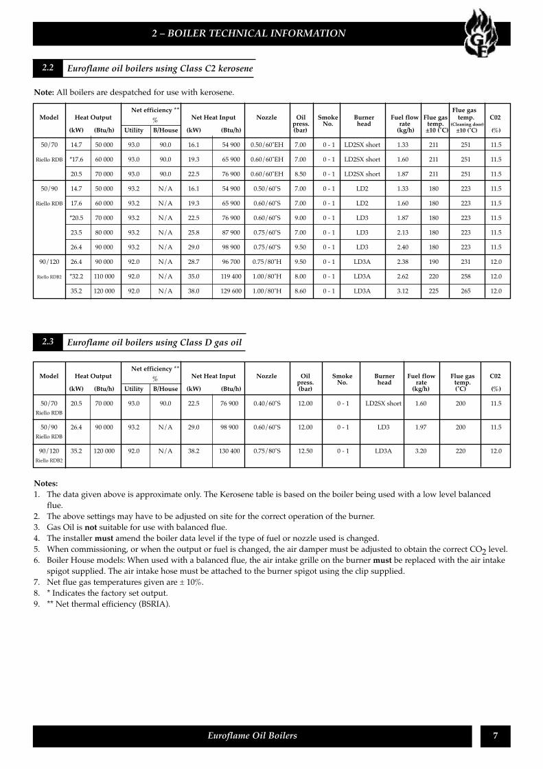
Model 50/70 50/90 System 50/90 90/120 90/120 System
Water content litre 14 21 21 22 22
gal 3.1 4.6 4.6 4.8 4.8
* Weight (dry) kg 55 (bh), 76 (ku) 117 100 (bh), 109 (ku) 112 (bh), 121 (ku) 129
(bh = Boiler House ku = Kitchen/Utility) lb 121 (bh), 167 (ku) 258 220 (bh), 240 (ku) 232 (bh), 252 (ku) 284
Max. heat input (Kerosene) kW 22.8 (bh), 22.0 (ku) 28.3 28.8 (bh), 28.3 (ku) 38.0 38.0
(BH = Boiler House KU = Kitchen/Utility) Btu/h 77 794 (BH), 75 067 (KU) 96 563 98 269 (BH), 96 563 (KU) 129 600 129 600
Flow (F) and return (R) connections 1” BSP 3/4" (F) 1"BSP (R) 1” BSP 11/4" BSP 1” (F) 11/4"BSP (R)
Flue size (conventional) 100 mm (4 in) diameter 125 mm (5 in) dia. 125 mm (5 in) dia.
Waterside resistance
Flow/Return temp. difference of 10˚C 26.5 mbar
Flow/Return temp. difference of 20˚C 9.5 mbar
Maximum static head 28 m
Minimum circulating head 1 m
Boiler thermostat range 65 to 85˚C (60 to 90˚C - Boiler House Models)
Limit (safety) stat switch off temp. 111˚C ± 3˚C
Max. hearth temperature Less than 50˚C
Electricity supply 230-240V ~ 50 Hz Fused at 5 Amp
Motor power 90 W max.
Starting current 2.60 Amp
Running current 0.85 Amp
Oil connection 1/4” BSP Male (on end of flexible fuel line)
Conventional flue Minimum flue draught - 8.7 N/m2 (0.035 in wg)
Maximum flue draught - 37 N/m2 (0.15 in wg)
Max. operating press. Sealed system 2.5 bar
Open system 3 bar 3 bar 3 bar 3 bar 3 bar
Max. heating system volume N/A 157 litre N/A N/A 157 litre
Expansion vessel (pre-charged 1 bar) N/A 12 litre N/A N/A 12 litre
* Weight includes burner but excludes flue
2 – BOILER TECHNICAL INFORMATION
7Euroflame Oil Boilers
Note: All boilers are despatched for use with kerosene.
Notes:1. The data given above is approximate only. The Kerosene table is based on the boiler being used with a low level balanced
flue.2. The above settings may have to be adjusted on site for the correct operation of the burner.3. Gas Oil is not suitable for use with balanced flue.4. The installer must amend the boiler data level if the type of fuel or nozzle used is changed.5. When commissioning, or when the output or fuel is changed, the air damper must be adjusted to obtain the correct CO2 level.6. Boiler House models: When used with a balanced flue, the air intake grille on the burner must be replaced with the air intake
spigot supplied. The air intake hose must be attached to the burner spigot using the clip supplied.7. Net flue gas temperatures given are ± 10%.8. * Indicates the factory set output.9. ** Net thermal efficiency (BSRIA).
2.2 Euroflame oil boilers using Class C2 kerosene
Net efficiency ** Flue gasModel Heat Output Net Heat Input Nozzle Oil Smoke Burner Fuel flow Flue gas temp. C02% press. No. head rate temp. (Cleaning door)
(kW) (Btu/h) Utility B/House (kW) (Btu/h) (bar) (kg/h) ±10 (˚C) ±10 (˚C) (%)
50/70 14.7 50 000 93.0 90.0 16.1 54 900 0.50/60˚EH 7.00 0 - 1 LD2SX short 1.33 211 251 11.5
Riello RDB *17.6 60 000 93.0 90.0 19.3 65 900 0.60/60˚EH 7.00 0 - 1 LD2SX short 1.60 211 251 11.5
20.5 70 000 93.0 90.0 22.5 76 900 0.60/60˚EH 8.50 0 - 1 LD2SX short 1.87 211 251 11.5
50/90 14.7 50 000 93.2 N/A 16.1 54 900 0.50/60˚S 7.00 0 - 1 LD2 1.33 180 223 11.5
Riello RDB 17.6 60 000 93.2 N/A 19.3 65 900 0.60/60˚S 7.00 0 - 1 LD2 1.60 180 223 11.5
*20.5 70 000 93.2 N/A 22.5 76 900 0.60/60˚S 9.00 0 - 1 LD3 1.87 180 223 11.5
23.5 80 000 93.2 N/A 25.8 87 900 0.75/60˚S 7.00 0 - 1 LD3 2.13 180 223 11.5
26.4 90 000 93.2 N/A 29.0 98 900 0.75/60˚S 9.50 0 - 1 LD3 2.40 180 223 11.5
90/120 26.4 90 000 92.0 N/A 28.7 96 700 0.75/80˚H 9.50 0 - 1 LD3A 2.38 190 231 12.0
Riello RDB2 *32.2 110 000 92.0 N/A 35.0 119 400 1.00/80˚H 8.00 0 - 1 LD3A 2.62 220 258 12.0
35.2 120 000 92.0 N/A 38.0 129 600 1.00/80˚H 8.60 0 - 1 LD3A 3.12 225 265 12.0
2.3 Euroflame oil boilers using Class D gas oil
Net efficiency **Model Heat Output Net Heat Input Nozzle Oil Smoke Burner Fuel flow Flue gas C02% press. No. head rate temp.
(kW) (Btu/h) Utility B/House (kW) (Btu/h) (bar) (kg/h) (˚C) (%)
50/70 20.5 70 000 93.0 90.0 22.5 76 900 0.40/60˚S 12.00 0 - 1 LD2SX short 1.60 200 11.5Riello RDB
50/90 26.4 90 000 93.2 N/A 29.0 98 900 0.60/60˚S 12.00 0 - 1 LD3 1.97 200 11.5Riello RDB
90/120 35.2 120 000 92.0 N/A 38.2 130 400 0.75/80˚S 12.50 0 - 1 LD3A 3.20 220 12.0Riello RDB2
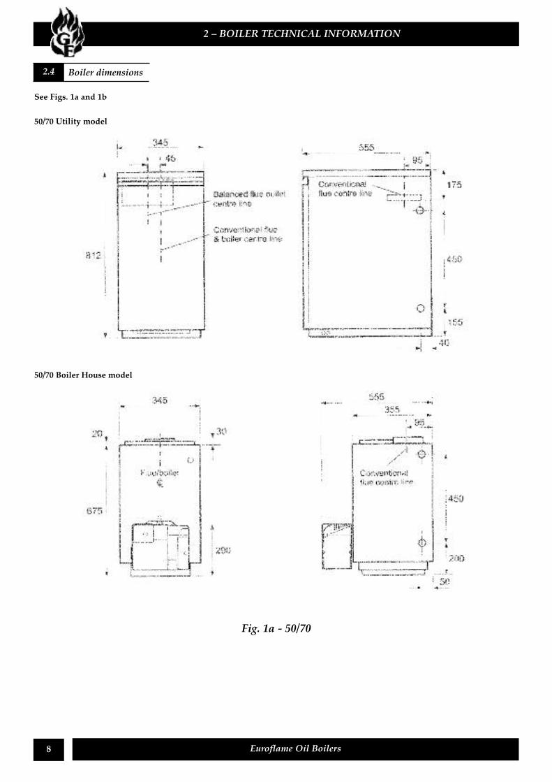
See Figs. 1a and 1b
2 – BOILER TECHNICAL INFORMATION
8 Euroflame Oil Boilers
50/70 Utility model
50/70 Boiler House model
Fig. 1a - 50/70
2.4 Boiler dimensions
2 – BOILER TECHNICAL INFORMATION
9Euroflame Oil Boilers
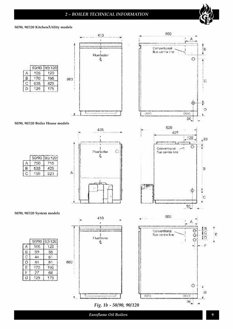
50/90, 90/120 Kitchen/Utility models
50/90, 90/120 Boiler House models
50/90, 90/120 System models
Fig. 1b - 50/90, 90/120
10 Euroflame Oil Boilers
The Euroflame range of automatic pressure jet oilboilers have been designed for use with a centralheating system with indirect domestic hot watercylinder. They are not suitable for use with either adirect cylinder or a ‘primatic’ cylinder.The boilers are also suitable for use on a sealed centralheating system.There are five versions of the Euroflame available, the50/70, 50/90 System. 50/90, 90/120 and 90/120System. The 50/70, 50/90 and 90/120 can be suppliedas Kitchen/Utility or uncased Boiler House models.The 50/70 can be adjusted to a maximum output of20.5 kW (70 000 Btu/h), the 50/90 26.4 kW (90 000Btu/h), and the 90/120 35 kW (120 000 Btu/h).The boilers are supplied as Conventional flue models,if a Balanced flue version is ordered, a Balanced FlueKit is required. Kits available include:- ConcentricLow Level Balanced Flue, and Concentric High LevelBalanced Flue, all suitable for left, right or rear outletand a Vertical Concentric Balanced Flue.Kitchen/Utility models are supplied with the burnerfactory fitted. The burners for Boiler House modelsare supplied in a separate carton. A burner supplycable is supplied pre-wired to all burners.The 50/90 & 90/120 Kitchen/Utility System boilersare sealed system version of the standard EuroflameKitchen/Utility boiler. They are supplied factory fittedwith a complete sealed system kit incorporating a 12litre expansion vessel, automatic air vent, pressurerelief safety valve assembly, pressure gauge and fillingloop. A circulating pump and isolating valves are alsofitted. Both the pump and burner are pre-wired forease of installation.All burners are pre-set for use with kerosene and aresupplied ready to connect to a single pipe fuel supplysystem with a loose flexible fuel line (630 mm) and3/8" to 1/4" BSP male adaptor supplied with the boiler.If required, an additional flexible fuel line (900 mm)and 3/8" to 1/4" BSP male adaptor are available fromlocal stockist for two-pipe oil line supply.All models are suitable for use with Class C 2kerosene or Class D gas oil. See sections 2.2 and 2.3.
If the fuel to be used is Gas Oil or the boiler output isto be changed, it may be necessary to change theburner nozzle and burner head. Refer to the TechnicalInformation in sections 2.2, and 2.3.To change the nozzle on the Kitchen/Utility model,remove the burner from the boiler then remove theburner head/nozzle as described in section 7.4. For aBoiler House model, unpack the burner and removethe burner head/nozzle as described in section 7.4The installer must amend the boiler data labelaccordingly.The temperature of the water leaving the boiler toheat the radiators and hot water cylinder is Useradjustable from 65 to 85˚C on Kitchen/Utility modelsand 60 to 90˚C on Boiler House models.The boilers are fitted with an overheat thermostat(allowing them to be used on a sealed central heatingsystems) which will automatically switch off theboiler if the heat exchanger exceeds at pre-settemperature of 111˚C ± 3˚C.The control panel fitted to the Kitchen/Utility andSystem models has an On/Off switch (with neonindicator light), boiler thermostat control knob andthe manual reset button for the overheat thermostat.The System models also have a system pressuregauge.Both Boiler House models are supplied with acombined boiler and overheat thermostat with aboiler thermostat control knob and the manual resetbutton for the overheat thermostat.The 50/90 and 90/120 Kitchen/Utility boiler alsocomes with the option of a timer. The boiler has to beordered with the timer fitted.
3 – GENERAL BOILER INFORMATION
3.1 Boiler description
Note: Only Kerosene may be used with LowLevel Balanced flues.
11Euroflame Oil Boilers
Installation of a Euroflame boiler must be inaccordance with the following recommendations:-a National Building Regulationsb Model and local Water Undertaking Byelawsc Applicable Control of Pollution Regulationsd The following OFTEC requirements:-OFST 100 Polythene oil storage tanks for
distillate fuels.OFST 200 Fuel oil storage tanks and tank
bunds for use with distillate fuelslubrication oils and waste oils.
Further information may be obtained from theOFTEC Technical Information Book 3(Installation requirements for oil fired boilers andoil storage tanks).
The installation should also be in accordance with thelatest edition of the following British Standard Codesof Practice:-BS 715 Metal flue pipes, fittings, terminals
and accessoriesBS 799 Oil storage tanksBS 1181 Clay flue linings and flue terminalsBS 4543:3 Factory made insulated
chimneys for oil fired appliancesBS 4876 Performance requirements for
oil burning appliancesBS 5410:1 Code of Practice for oil firing appliancesBS 5449 Forced circulation hot water systemsBS 7593 Code of Practice for treatment of water
in heating systemsBS 7671 Requirements for electrical installations,
IEE Wiring Regulations
Kitchen/Utility Conventional flue models aresupplied in one pack, containing the cased boiler withthe burner and control panel fitted, and literaturepack.
Kitchen/Utility models are supplied in two packs,containing the following:-
Carton 1 The cased boiler with burner fitted andcontrol panel, and literature pack.
Carton 2 The balanced flue kit – low, high levelor vertical, as ordered. A terminal guardis supplied with a low level flue kit.
Boiler House Conventional flue models are suppliedin three packs, containing the following:-
Carton 1 The boiler with literature pack, butwithout burner.
Carton 2 The burnerCarton 3 The combined boiler and overheat
thermostat.
Boiler House Balanced flue models are supplied infour packs as follows:-
Carton 1 The boiler with literature pack, butwithout burner.
Carton 2 The burnerCarton 3 The combined boiler and overheat
thermostat.Carton 4 The balanced flue kit - low level, high
level or vertical as ordered. A terminalguard is supplied with a low level fluekit.
The following flue kits are available, refer to section3.8 for further details.
a Low level concentric balanced flue.b Low level concentric balanced flue extensions,
225 mm, 450 mm and 675 mm.c 90˚ concentric bendd High level balanced flue.e High level balanced flue extensions.f Vertical balanced flue.g Vertical balanced flue extensions.h 45˚ elbows for high level and vertical
balanced flues.
3 – GENERAL BOILER INFORMATION
3.2 Regulations to comply with 3.3 Delivery
Failure to install and commission appliancescorrectly may invalidate the boiler warranty.
It is recommended that the appliance is installed, commissioned and maintained by anOFTEC registered or Grant approved technician.
IMPORTANTBefore starting any work on the boiler, or fuelsupply please read the health and safetyinformation given in section 11 on page 41.
12 Euroflame Oil Boilers
3.4.1 Fuel storageA painted (outside only) storage tank must beconstructed to BS 799:5:1987 and should include thefollowing:-
a A fuel level gauge (not a glass type).b A vent pipe incorporating a weatherproof
termination (bend or cap) of a diameter notless than the filling pipe.
c A sludge valve.d An outlet valve at the opposite end of the
tank to the sludge valve.
The tank should be positioned in accordance with therecommendations given in BS 5410:1:1997, whichgives details of filling, maintenance and protectionfrom fire.The tank should be suitably supported so as to obtaina slope of 20 mm per metre towards the sludge valve.A galvanised tank must not be used.A plastic tank may be used and must comply withOFS T100.
3.4.2 Fuel pipes1. Fuel supply pipes should be of copper tubing
with an internal diameter of at least 8 mm.Soldered joints should not be used.Galvanised pipe must not be used.
2. Flexible pipes must not be used outside the boilercase.
3. A remote sensing fire valve must be installed inthe fuel supply line (outside) where it enters thebuilding, with the sensing head located above theburner. Recommendations are given in BS5410:1:1997.
4. A metal bowl type filter with a replaceablemicronic filter must be fitted in the fuel supplyline adjacent to the boiler. A shut-off valve shouldbe fitted before the filter, to allow the filter to beserviced.
5. A flexible fuel line, adaptor and 1/4” BSP isolationvalve are supplied loose with the boiler for thefinal connection to the burner. If a two pipesystem or Tiger Loop system is used an additionalflexible fuel line (630 mm) and 3/8” to 1/4” BSPmale adaptor are available from your localstockist.
6. Flexible pipes should be inspected annually whenthe boiler is serviced and replaced every twoyears.
7. The use of a ‘Tankmaster’ and Tiger Loop is anideal way of delivering an oil supply to the boiler.The Tankmaster unit, fitted to the storage tank,includes a filter, sight tube, shut-off valve and firevalve. A separate fire valve is required in the fuelline (outside) where it enters the room containingthe boiler. See Fig. 4.
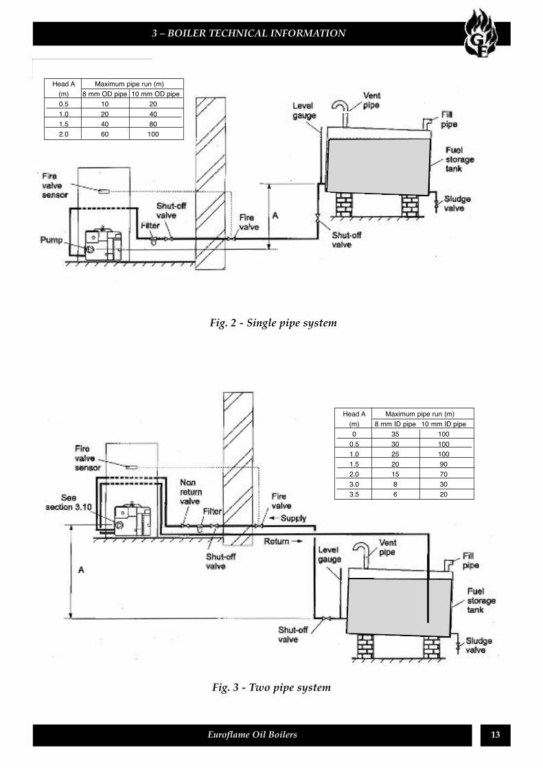
3.4.3 Single pipe system (See Fig. 2)1 Where the storage tank outlet is above the burner
the single pipe system should be used. The heightof the tank above the burner limits the length ofpipe run from the tank to the burner.
2. As supplied the burner is suitable for a singlepipe system.
3.4.4 Two pipe system (See Fig. 3)1 When the storage tank outlet is below the burner,
the two pipe system should be used. The piperuns should be as shown in Fig. 3. The return pipeshould be at the same level in the tank as thesupply pipe, both being 75 to 100 mm above thebase of the tank. The pipe ends should be asufficient distance apart so as to prevent anysediment disturbed by the return entering thesupply pipe.
2 Avoid the bottom of the tank being more than 3 mbelow the burner.
3 A non-return valve should be fitted in the supplypipe together with the filter and fire valve. Thereturn pipe must be unrestricted.
5 The pump vacuum should not exceed 0.4 bar.Beyond this limit gas is released from the oil.
3 – GENERAL BOILER INFORMATION
3.4 Fuel supply
Note: Plastic tanks should be adequately anduniformly supported on a smooth level surface,across their entire base area.
4. To be used with a two-pipe system, the burnermust be fitted with an additional flexible fuelline (a flexible fuel line (630 mm) and 3/8” to 1/4”BSP male adaptor are available from your localstockist. See section 3.4.6.
For guidance an installation of top outlet fueltanks and suction oil supply sizing, see OFTECbooklet T1/139. Available at www.oftec.org.uk
3 – BOILER TECHNICAL INFORMATION
13Euroflame Oil Boilers
Fig. 2 - Single pipe system
Fig. 3 - Two pipe system
Head A Maximum pipe run (m)(m) 8 mm ID pipe 10 mm ID pipe0 35 1000.5 30 1001.0 25 1001.5 20 902.0 15 703.0 8 303.5 6 20
Head A Maximum pipe run (m)(m) 8 mm OD pipe 10 mm OD pipe0.5 10 201.0 20 401.5 40 802.0 60 100
14 Euroflame Oil Boilers
3.4.5 Tiger Loop system (See Figs. 4 & 5)1 When the storage tank is below the burner, an
alternative to a two pipe system can be achievedusing the Tiger Loop oil deaerator. This effectivelyremoves the air from the oil supply on a singlepipe lift.
2 The Tiger Loop is connected close to the boiler asa two pipe system (omitting the non-return valve)as shown in Fig. 4. Refer to the manufacturersinstructions supplied with the Tiger Loop.The Tiger Loop must be mounted vertically.
3 To be used with a Tiger Loop system, the burnermust be fitted with an additional flexible fuel line(a flexible fuel line (900 mm) and 3/8” to 1/4” BSPmale adaptor are available from your localstockist). See section 3.4.6.
3 – GENERAL BOILER INFORMATION
Fig. 5 - Tiger loop
Fig. 4- Tiger loop system
Note: To prevent any possibility of fuel fumesentering the building, the Tiger Loop must befitted outside.
15Euroflame Oil Boilers
3.4.6 Two pipe oil suppliesRiello RDB burner - See Fig. 61 The fuel pump is supplied for use with a single
pipe supply system. For use on a two pipesystem, it is necessary to fit the By-pass screw (seeFig. 6) into the tapping in the return port.
2. The By-pass screw is supplied in the boileraccessory pack.
3. Remove the plastic burner cover (two screws). Togain access on Kitchen models, it may benecessary to remove the grey plinth - loosen thescrew securing the right hand side of the plinth,then withdraw the plinth forward from the rightand away from the case.
4. Remove and discard the blanking plug from thereturn connection of the pump and fit the By-passscrew using an hexagonal key.
5. Connect the return oil flexible fuel line to thepump.
6. Connect the 3/8” to 1/4” BSP adaptor to theflexible fuel line.
7. Flexible fuel lines and adaptors are available fromlocal stockist.
8. Boiler House models - Fit the burner as describedin section 4.6.
1 A 230/ 240 V ~ 50 Hz mains supply is required.The boiler must be earthed.
2 The supply must be fused at 5 Amp and theremust only be one common isolator for the boilerand control system, and it must provide completeelectrical isolation.
3. A fused double pole switch or a fused three pinplug and shuttered outlet socket should be usedfor the connection.
4. The power supply cable should be at least 0.75mm2 PVC as specified in BS 6500, Table 16.
5. All the wiring external to the boiler must be inaccordance with the current I.E.E. WiringRegulations.
6. Any room thermostat or frost thermostat usedmust be suitable for use on mains voltage.
7. In the event of an electrical fault after installationof the boiler, the following electrical systemchecks must be carried out:- Short circuit, Polarity,Earth continuity and Resistance to earth.
See Figs. 7 and 8A sufficient permanent air supply to the boiler shouldbe provided:a For proper combustion of fuel and effectivedischarge of combustion products to the open air.
b For the ventilation of any confined space inwhich the boiler is installed to preventoverheating of the boiler any equipment in andnear the boiler.
c For the satisfactory operation of any draughtstabiliser which may be fitted.
It should be both the designer’s and installer’sconcern that the air required for these functions beintroduced so as to cause as little discomfort aspossible to the building occupants and thus to offerthem the least temptation to obstruct the ventilators.Further details may be obtained from BS 5410:1:1997.
3 – GENERAL BOILER INFORMATION
3.6 Air supply
Notes:For a boiler fitted in a compartment, which isventilated as shown, no additional allowance isnecessary.Open flue - Extract fans, where needed, should bein accordance with section 4.4.7 in BS 5410 Part 11997/
3.5 Electricity supply
Fig. 6 - Riello RDB pump
16 Euroflame Oil Boilers
3 – GENERAL BOILER INFORMATION
Fig. 7 – Air supply for room sealed balanced flue boilers
Fig. 8 – Combustion and ventilation air supply for conventional flue boilers
17Euroflame Oil Boilers
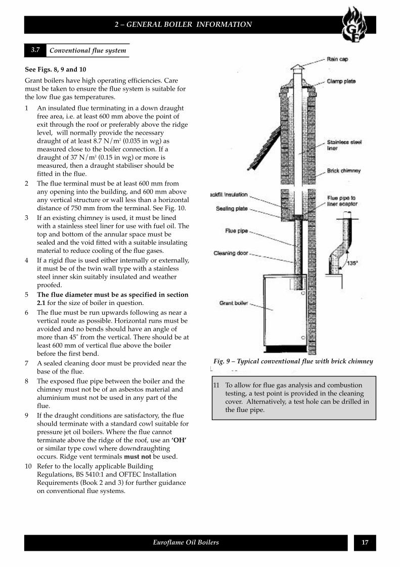
See Figs. 8, 9 and 10Grant boilers have high operating efficiencies. Caremust be taken to ensure the flue system is suitable forthe low flue gas temperatures.1 An insulated flue terminating in a down draught
free area, i.e. at least 600 mm above the point ofexit through the roof or preferably above the ridgelevel, will normally provide the necessarydraught of at least 8.7 N/m2 (0.035 in wg) asmeasured close to the boiler connection. If adraught of 37 N/m2 (0.15 in wg) or more ismeasured, then a draught stabiliser should befitted in the flue.
2 The flue terminal must be at least 600 mm fromany opening into the building, and 600 mm aboveany vertical structure or wall less than a horizontaldistance of 750 mm from the terminal. See Fig. 10.
3 If an existing chimney is used, it must be linedwith a stainless steel liner for use with fuel oil. Thetop and bottom of the annular space must besealed and the void fitted with a suitable insulatingmaterial to reduce cooling of the flue gases.
4 If a rigid flue is used either internally or externally,it must be of the twin wall type with a stainlesssteel inner skin suitably insulated and weatherproofed.
5 The flue diameter must be as specified in section2.1 for the size of boiler in question.
6 The flue must be run upwards following as near avertical route as possible. Horizontal runs must beavoided and no bends should have an angle ofmore than 45˚ from the vertical. There should be atleast 600 mm of vertical flue above the boilerbefore the first bend.
7 A sealed cleaning door must be provided near thebase of the flue.
8 The exposed flue pipe between the boiler and thechimney must not be of an asbestos material andaluminium must not be used in any part of theflue.
9 If the draught conditions are satisfactory, the flueshould terminate with a standard cowl suitable forpressure jet oil boilers. Where the flue cannotterminate above the ridge of the roof, use an ‘OH’or similar type cowl where downdraughtingoccurs. Ridge vent terminals must not be used.
10 Refer to the locally applicable BuildingRegulations, BS 5410:1 and OFTEC InstallationRequirements (Book 2 and 3) for further guidanceon conventional flue systems.
2 – GENERAL BOILER INFORMATION
Fig. 9 – Typical conventional flue with brick chimney
3.7 Conventional flue system
11 To allow for flue gas analysis and combustiontesting, a test point is provided in the cleaningcover. Alternatively, a test hole can be drilled inthe flue pipe.
18 Euroflame Oil Boilers
Kitchen/Utility models1 Lift off the two case top panels.2 Remove the insulation from the smaller panel (do
not discard it) and remove knock-out.3 Cut a clearance hole in the insulation.4 Place the first section of the flue pipe through the
panel and locate it into the boiler flue socket.5 Make good the connection using a suitable
flexible high temperature sealant (e.g. Silastic orsimilar) and a rope seal and replace the insulation.
6 Fit the dress plate supplied, to the top panel.Boiler House models1 Position the flue pipe into the boiler flue socket.2 Make good the connection using a suitable
flexible high temperature sealant (e.g. Silastic orsimilar) and a rope seal.
1 Apart from a conventional flue/chimney, severalbalanced flue options are available for use withthe Kitchen/Utility and Boiler House models.a Concentric low level horizontal balanced
flue- available in Standard kit. Extensions areavailable which extend the flue by 225 mm,450 mm or 675 mm.90˚ and 45˚ extension elbows and a 45˚ elboware also available.The maximum flue length with or withoutelbows is 2 m.
b High level horizontal balanced flue - allowsthe flue to rise between approximately 1.7 to2.2 m above floor level before exiting throughthe rear or side wall. It is adjustable to suit thefollowing wall thicknesses:-
Rear 215 to 450mm (approximately)Side 120 to 350mm (approximately)
Extension kits are available which extend theflue by 950 mm, 450 mm or 275 to 450 mmtelescopic.
c A vertical balanced flue kit - adjustable to3 m (maximum 6 m with extensions).Extension kits are available which extend theflue by 950 mm, 450 mm or 275 to 450 mmtelescopic. A choice of two waterproofflashings (flat or pitched) and a wall bracketare also available.
The wall thicknesses quoted above for side flueassumes that the boiler will be spaced off the wall bya nominal 20 mm (to provide clearance for the plugsfor the water connections). Water connections may betaken from one side only, if required (see paragraph 2in section 3.12).
3 – GENERAL BOILER INFORMATION
3.8 Connect a conventional flue
3.8 Balanced flue options
Standard Kit To suit wall thickness mmRear Exit Side Exit
Min. Max. Min. Max.50/70 Boiler House 280 460 180 36050/90 Boiler House 250 430 140 32090/120 Boiler House 250 430 130 29050/70 Kitchen/Utility 290 470 180 36050/90 Kitchen/Utility 260 440 150 33050/90 System 260 440 150 33090/120 Kitchen/Utility 270 450 140 30090/120 System 270 450 140 300
19Euroflame Oil Boilers
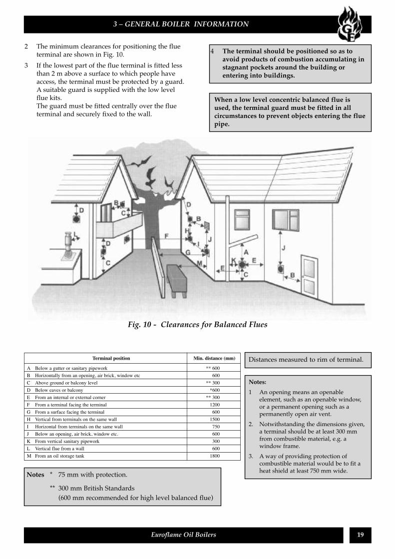
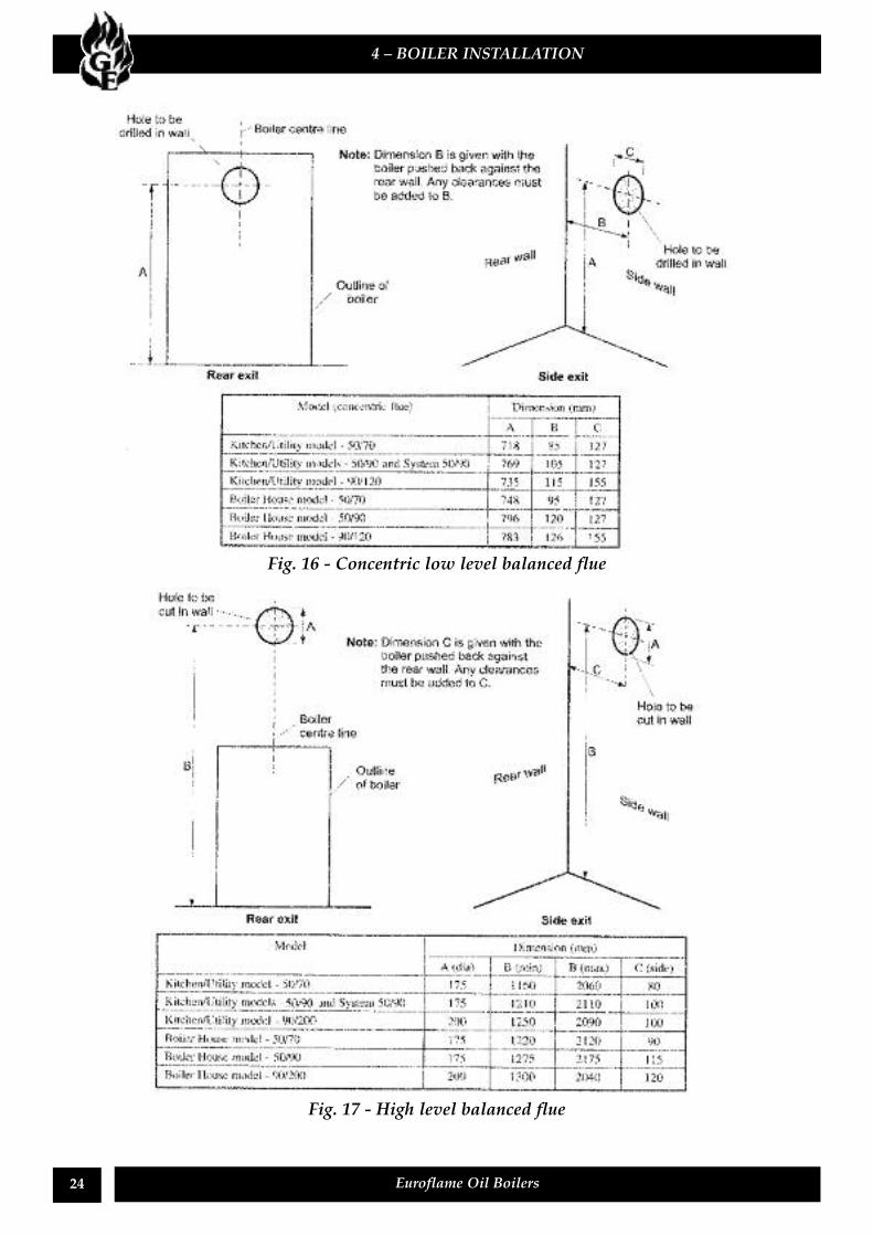
2 The minimum clearances for positioning the flueterminal are shown in Fig. 10.
3 If the lowest part of the flue terminal is fitted lessthan 2 m above a surface to which people haveaccess, the terminal must be protected by a guard.A suitable guard is supplied with the low levelflue kits.The guard must be fitted centrally over the flueterminal and securely fixed to the wall.
3 – GENERAL BOILER INFORMATION
4 The terminal should be positioned so as toavoid products of combustion accumulating instagnant pockets around the building orentering into buildings.
When a low level concentric balanced flue isused, the terminal guard must be fitted in allcircumstances to prevent objects entering the fluepipe.
Notes * 75 mm with protection.** 300 mm British Standards(600 mm recommended for high level balanced flue)
Fig. 10 - Clearances for Balanced Flues
Terminal position Min. distance (mm)
A Below a gutter or sanitary pipework ** 600B Horizontally from an opening, air brick, window etc 600C Above ground or balcony level ** 300D Below eaves or balcony *600E From an internal or external corner ** 300F From a terminal facing the terminal 1200G From a surface facing the terminal 600H Vertical from terminals on the same wall 1500I Horizontal from terminals on the same wall 750J Below an opening, air brick, window etc. 600K From vertical sanitary pipework 300L Vertical flue from a wall 600M From an oil storage tank 1800
Distances measured to rim of terminal.
Notes:1 An opening means an openable
element, such as an openable window,or a permanent opening such as apermanently open air vent.
2. Notwithstanding the dimensions given,a terminal should be at least 300 mmfrom combustible material, e.g. awindow frame.
3. A way of providing protection ofcombustible material would be to fit aheat shield at least 750 mm wide.
20 Euroflame Oil Boilers
For additional protection of either the entire heatingsystem, or the boiler and localised pipework, it isrecommended that a frost thermostat be installed.Refer to section 8 for connection details.To protect the heating system the frost thermostatshould be sited within the house in such a place that itcan detect any rise and fall in the ambient airtemperature, i.e. in a room with a radiator.Where the frost thermostat is installed outside thehouse (to protect a boiler installed in an externalboiler room or garage) or in an attic, it isrecommended that it be used in conjunction with apipe thermostat to avoid unnecessary and wastefuloverheating of the property. The pipe thermostatshould be located on the boiler return pipe, and set tooperate at 25˚C. Refer to section 8 for connectiondetails.
1 The boiler must stand on a surface that is firm andlevel. It does not require a special hearth as thetemperature of the boiler base is less than 50˚C.
2 Sufficient clearance must be allowed around theboiler for the following:-Access above the boiler to remove the baffles forservicing.Access at the front of the boiler to remove theburner.
3 If the boiler is to be installed with a side against awall, allow a nominal clearance of 20 mm for theplugs for the water connections. Water connectionsmay be taken from one side only if required (seesection 3.12, paragraph 2).
1 A high level flow and low level return connectionare provided on each side of the boiler. See Fig. 1.1” BSP connections are used on 50/70, 50/90models and 11/4" on 90/120 models.
2 Flow and return connections should preferably bediagonally opposed, i.e. to opposite sides of theboiler. If the boiler is to be positioned against awall, the water connections may be taken from oneside only.
3 All models have a tapping (1/2” BSP) on the frontfor the thermostat pocket, (pocket supplied loosewith Boiler House models).
4. Plug all unused connections.5 Fit drain taps in the central heating and domestichot water systems to allow the complete system tobe fully drained.
6 Thoroughly flush the system before fitting thepump.
System boilerThe system pipework may exit the boiler from eitherthe left hand or right side of the boiler casing. See Fig. 1.1 Fit any elbows, bushes etc. to the heating returntapping at the bottom (1” BSP 50/90 or 11/4" BSP90/120) before placing the boiler in position ifaccess is restricted. Do not forget to plug theunused connection on the opposite side.
2 The heating flow pipe (3/4" 50/90 or 1" 90/120)and 1/2" safety valve discharge pipe are providedwith elbows to enable quick and simpleinstallation.The 90/120 boiler is supplied with a 1" flow pipefactory fitted for left hand side exit. A 1" elbow isprovided for easy connection of the heating systempipework.If required, the flow pipe may exit through theright hand side panel. The 28 mm factory fittedflow pipe must be turned 90˚ and routed across theboiler behind the control panel.
3 The safety valve discharge pipe must be routedclear of the boiler to the outside, to discharge insuch a manner that the discharge can be seen butcannot cause injury or damage to persons orproperty.
4 The cold fill shut off valve should be fitted in anaccessible position close to the boiler to enableconnection of the temporary flexible filling loop tothe boiler.
3 – GENERAL BOILER INFORMATION
3.10 Frost protection
3.11 Boiler location
3.12a Water connections
3.12 Water connections
Important: Care must be taken not to obstruct thecleaning cover door on top of the boiler asremoval of the door and the boiler baffles willnot be possible.
21Euroflame Oil Boilers
3 – GENERAL BOILER INFORMATION
Fig. 12 - Gravity domestic hot water system
3.13 Heating system diagrams
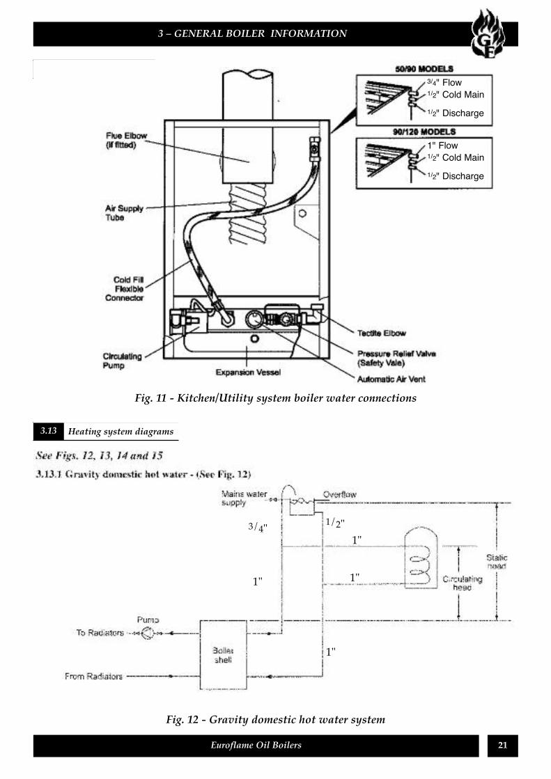
Fig. 11 - Kitchen/Utility system boiler water connections
3/4" 1/2"
1"
1"
1"
1"
3/4" Flow1/2" Cold Main1/2" Discharge
1" Flow1/2" Cold Main1/2" Discharge
22 Euroflame Oil Boilers
3.12.3 Kitchen/Utility sealed system - (See Fig. 14)1 The boiler is suitable only for use with a sealedsystem complying with the requirements of BS5449.The maximum temperature of the central heatingwater is 85˚C.
2 The boiler is supplied with the following itemsfactory fitted:-a A diaphragm expansion vessel complying withBS 4814, pre-charged at 1.0 bar.
b System pressure gauge, with an operating rangeof 1 to 4 bar.
c Pressure relief safety valve complying with BS6759 and set to operate at 3 bar.
d Circulating pump with isolating valves.e Automatic air vent.f Filling loop. This must be isolated anddisconnected after filling the system.
3 The central heating system volume, using theexpansion vessel as supplied, must not exceed thevolume shown in section 2.1. For further guidancerefer to BS 7074:1.Refer to section 4.13 for further details of theexpansion vessel.
4 The system design pressure (cold) should bebetween 0.5 and 1.0 bar. This pressure is equivalentto the maximum static head (see Fig. 14) in bar +0.3 (1 bar = 10.2 metres of water).
5 If thermostatic radiator valves are fitted to allradiators, a system by-pass must be fitted.
6 Provision should be made to replace water lostfrom the system. This may be done manually(where allowed by the local Water Undertaking)using the filling loop arrangement supplied withthe boiler.
3 – GENERAL BOILER INFORMATION
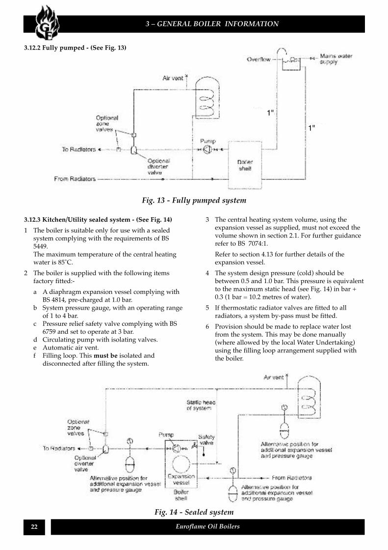
3.12.2 Fully pumped - (See Fig. 13)
Fig. 13 - Fully pumped system
Fig. 14 - Sealed system
1"1"
23Euroflame Oil Boilers
7 Filling of the system must be carried out in amanner approved by the local Water Undertaking.Where allowed, the system may be filled via thefilling loop supplied (the loop arrangementincludes a double check valve assembly).
8 All fittings used in the system must be able towithstand pressures up to 3 bar.
9 Radiator valves must comply with therequirements of BS 2767(10): 1972.
10 One or more drain taps (to BS 2879) must be usedto allow the system to be completely drained.
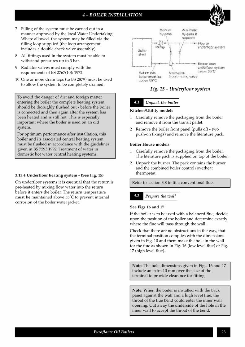
3.13.4 Underfloor heating system - (See Fig. 15)On underfloor systems it is essential that the return ispre-heated by mixing flow water into the returnbefore it enters the boiler. The return temperaturemust be maintained above 55˚C to prevent internalcorrosion of the boiler water jacket.
Kitchen/Utility models1 Carefully remove the packaging from the boilerand remove it from the transit pallet.
2 Remove the boiler front panel (pulls off - twopush-on fixings) and remove the literature pack.
Boiler House models1 Carefully remove the packaging from the boiler.The literature pack is supplied on top of the boiler.
2 Unpack the burner. The pack contains the burnerand the combined boiler control/overheatthermostat.
See Figs 16 and 17If the boiler is to be used with a balanced flue, decideupon the position of the boiler and determine exactlywhere the flue will pass through the wall.Check that there are no obstructions in the way, thatthe terminal position complies with the dimensionsgiven in Fig. 10 and them make the hole in the wallfor the flue as shown in Fig. 16 (low level flue) or Fig.17 (high level flue).
4 – BOILER INSTALLATION
4.1 Unpack the boilerTo avoid the danger of dirt and foreign matterentering the boiler the complete heating systemshould be thorughly flushed out - before the boileris connected and then again after the system hasbeen heated and is still hot. This is especiallyimportant where the boiler is used on an oldsystem.For optimum performance after installation, thisboiler and its associated central heating systemmust be flushed in accordance with the guidelinesgiven in BS 7593:1992 'Treatment of water indomestic hot water central heating systems'.
Refer to section 3.8 to fit a conventional flue.
4.2 Prepare the wall
Note: The hole dimensions given in Figs. 16 and 17include an extra 10 mm over the size of theterminal to provide clearance for fitting.
Note:When the boiler is installed with the backpanel against the wall and a high level flue, thethroat of the flue bend could enter the inner wallopening. Cut away the underside of the hole in theinner wall to accept the throat of the bend.
Fig. 15 - Underfloor system
24 Euroflame Oil Boilers
4 – BOILER INSTALLATION
Fig. 16 - Concentric low level balanced flue
Fig. 17 - High level balanced flue
25Euroflame Oil Boilers
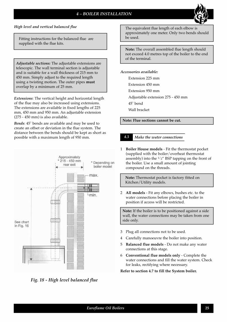
High level and vertical balanced flue
Extensions: The vertical height and horizontal lengthof the flue may also be increased using extensions.The extensions are available in fixed lengths of 225mm, 450 mm and 950 mm. An adjustable extension(275 - 450 mm) is also available.Bends: 45˚ bends are available and may be used tocreate an offset or deviation in the flue system. Thedistance between the bends should be kept as short aspossible with a maximum length of 950 mm.
Accessories available:Extension 225 mmExtension 450 mmExtension 950 mmAdjustable extension 275 - 450 mm45˚ bendWall bracket
1 Boiler House models - Fit the thermostat pocket(supplied with the boiler/overheat thermostatassembly) into the 1/2” BSP tapping on the front ofthe boiler. Use a small amount of jointingcompound on the threads.
2 All models - Fit any elbows, bushes etc. to thewater connections before placing the boiler inposition if access will be restricted.
3 Plug all connections not to be used.4 Carefully manoeuvre the boiler into position.5 Balanced flue models - Do not make any waterconnections at this stage.
6 Conventional flue models only - Complete thewater connections and fill the water system. Checkfor leaks, rectifying where necessary.
Refer to section 4.7 to fill the System boiler.
4 – BOILER INSTALLATION
Fitting instructions for the balanced flue aresupplied with the flue kits.
The equivalent flue length of each elbow isapproximately one meter. Only two bends shouldbe used.
Note: Flue sections cannot be cut.
Adjustable sections: The adjustable extensions aretelescopic. The wall terminal section is adjustableand is suitable for a wall thickness of 215 mm to450 mm. Simply adjust to the required lengthusing a twisting motion. The outer pipes mustoverlap by a minimum of 25 mm.
Note: The overall assembled flue length shouldnot exceed 4.0 metres top of the boiler to the endof the terminal.
Fig. 18 - High level balanced flue
4.3 Make the water connections
Note: If the boiler is to be positioned against a sidewall, the water connections may be taken from oneside only.
Note: Thermostat pocket is factory fitted onKitchen/Utility models.
26 Euroflame Oil Boilers
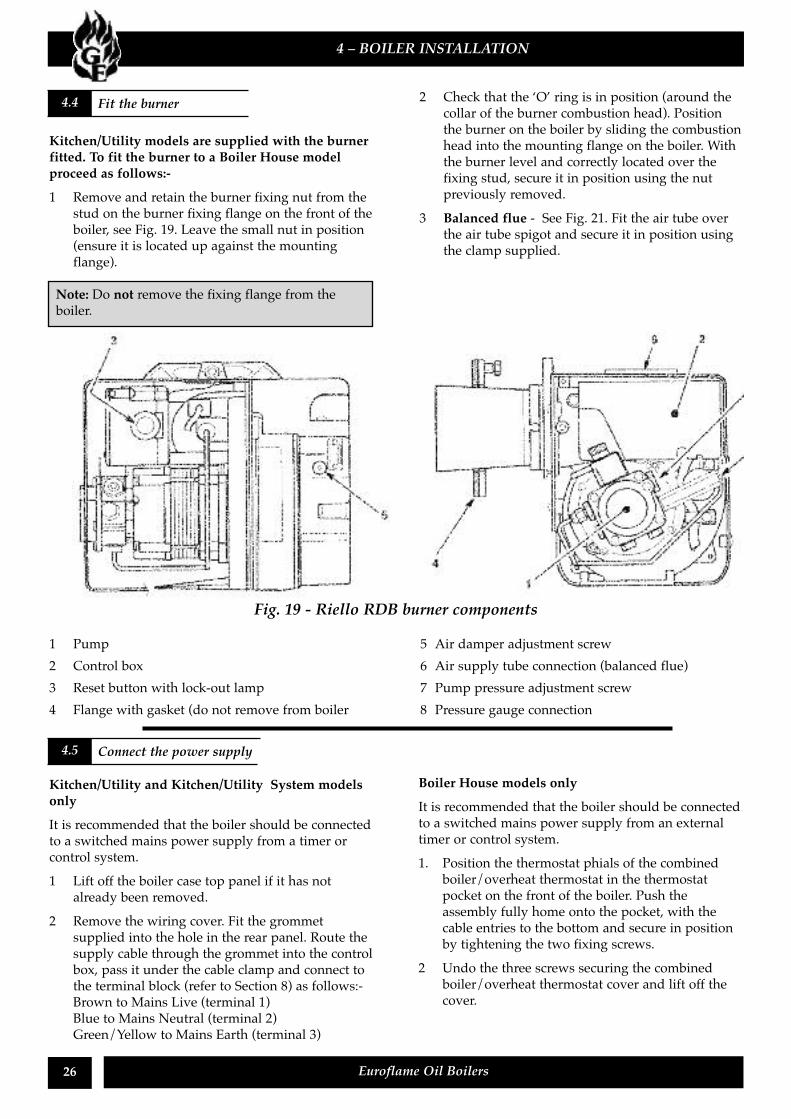
Kitchen/Utility models are supplied with the burnerfitted. To fit the burner to a Boiler House modelproceed as follows:-1 Remove and retain the burner fixing nut from the
stud on the burner fixing flange on the front of theboiler, see Fig. 19. Leave the small nut in position(ensure it is located up against the mountingflange).
2 Check that the ‘O’ ring is in position (around thecollar of the burner combustion head). Positionthe burner on the boiler by sliding the combustionhead into the mounting flange on the boiler. Withthe burner level and correctly located over thefixing stud, secure it in position using the nutpreviously removed.
3 Balanced flue - See Fig. 21. Fit the air tube overthe air tube spigot and secure it in position usingthe clamp supplied.
Kitchen/Utility and Kitchen/Utility System modelsonlyIt is recommended that the boiler should be connectedto a switched mains power supply from a timer orcontrol system.1 Lift off the boiler case top panel if it has not
already been removed.2 Remove the wiring cover. Fit the grommet
supplied into the hole in the rear panel. Route thesupply cable through the grommet into the controlbox, pass it under the cable clamp and connect tothe terminal block (refer to Section 8) as follows:-Brown to Mains Live (terminal 1)Blue to Mains Neutral (terminal 2)Green/Yellow to Mains Earth (terminal 3)
Boiler House models onlyIt is recommended that the boiler should be connectedto a switched mains power supply from an externaltimer or control system.1. Position the thermostat phials of the combined
boiler/overheat thermostat in the thermostatpocket on the front of the boiler. Push theassembly fully home onto the pocket, with thecable entries to the bottom and secure in positionby tightening the two fixing screws.
2 Undo the three screws securing the combinedboiler/overheat thermostat cover and lift off thecover.
4 – BOILER INSTALLATION
4.4 Fit the burner
Note: Do not remove the fixing flange from theboiler.
Fig. 19 - Riello RDB burner components
1 Pump 5 Air damper adjustment screw2 Control box 6 Air supply tube connection (balanced flue)3 Reset button with lock-out lamp 7 Pump pressure adjustment screw4 Flange with gasket (do not remove from boiler 8 Pressure gauge connection
4.5 Connect the power supply
27Euroflame Oil Boilers
3 Withdraw the cable support bushes from thecover. Pass the burner supply cable through oneof the bushes and connect it to the boiler (control)thermostat (refer to Fig. 29) as follows:-
Brown to terminal 1 on the control thermostatGreen/Yellow to the earth terminal, marked, on the control thermostat
4 Pass a switched mains power supply through theother cable support bush and connect it to theoverheat thermostat (refer to Fig. 29) as follows:-Switched live (brown) to terminal C on theoverheat thermostatEarth (green/yellow) and earth fly lead fromcasing to the earth terminal, marked , on theoverheat thermostatThe Blue (neutral) wire from the burner supplymust be linked to the incoming neutral ofswitched mains supply using a single connector(not supplied).Refer to section 8.4. For other systems not covered,contact Grant Engineering (Ireland) Ltd.
5 Connect a link between terminal 2 on the overheatthermostat and terminal C on the controlthermostat.
6 There are no connections to terminal 1 on theoverheat thermostat and terminal 2 on thecontrol thermostat.
7 Position the support bushes so as not to strain theconnections when the cover is replaced.Place the cover in position locating the bushes atthe same time.Note: It may be necessary to rotate the thermostatknob to engage it on the operating spindle as thecover is replaced.
8 Secure the cover in position by tightening thethree screws. Tighten the cable support bush nutsto secure the cables.
9 Ensure that all external wiring is adequatelysupported.
Do not switch on the electricity supply at this stage.
See Fig. 6
1 Remove the plug from the burner oil inlet adaptorand connect the elbow of the flexible fuel linesupplied with the boiler.
2 Connect the flexible pipe to the rigid supply usingthe adaptor supplied. For Kitchen/Utility modelsthe supply enters through one of the holes at thebottom of the case sides or the back panel.
Expansion vessel pressureThe expansion vessel fitted is supplied with a chargepressure of 1.0 bar (equivalent to a max. static head of10.2 metres). The charge pressure must not be lessthan the actual static head at the point of connection(see Fig. 14). Do not pressurise the vessel above 1.5bar.
The central heating system volume, using theexpansion vessel as supplied, must not exceed 107litres. If the system volume is greater, an extraexpansion vessel (complying with BS 4841) must befitted as close as possible to the central heating returnconnection on the boiler. The charge pressure of theextra vessel must be the same as the vessel fitted inthe boiler. Refer to BS 7074:1 for further guidance.
A simple test to check if the expansion vessel size isadequate is to fully fill the system cold to 1.0 bar, thenfully heat the system and if the pressure rises no morethan 2.0 bar the vessel is adequate. A higher figureindicates that an extra vessel is required.Fill the system1 An automatic air vent is fitted to the top of the
boiler (see Fig. 20). Check that the small cap onthe top of the air vent is screwed on fully, thenunscrew it one complete turn - the cap remains inthis position from now on.
2 Ensure that any valves in the heating systempipework are open.
4 – BOILER INSTALLATION
4.6 Connect the fuel supply
DO NOT connect the neutral wires to either of thetwo thermostats.
If a two pipe system is to be used refer to section3.4.8.
4.7 Fill and vent a sealed system
The air pressure in the vessel must be checked annually.
The air charge pressure may be checked using a tyrepressure gauge on the expansion vessel Schraedervalve. The vessel may be re-pressurised using asuitable pump. When checking the air pressure thewater in the heating system must be cold and thesystem pressure reduced to zero.
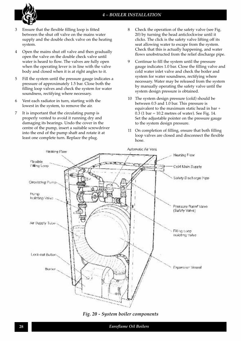
3 Ensure that the flexible filling loop is fittedbetween the shut off valve on the mains watersupply and the double check valve on the heatingsystem.
4 Open the mains shut off valve and then graduallyopen the valve on the double check valve untilwater is heard to flow. The valves are fully openwhen the operating lever is in line with the valvebody and closed when it is at right angles to it.
5 Fill the system until the pressure gauge indicates apressure of approximately 1.5 bar. Close both thefilling loop valves and check the system for watersoundness, rectifying where necessary.
6 Vent each radiator in turn, starting with thelowest in the system, to remove the air.
7 It is important that the circulating pump isproperly vented to avoid it running dry anddamaging its bearings. Undo the cover in thecentre of the pump, insert a suitable screwdriverinto the end of the pump shaft and rotate it atleast one complete turn. Replace the plug.
8 Check the operation of the safety valve (see Fig.20) by turning the head anticlockwise until itclicks. The click is the safety valve lifting off itsseat allowing water to escape from the system.Check that this is actually happening, and waterflows unobstructed from the relief discharge pipe.
9 Continue to fill the system until the pressuregauge indicates 1.0 bar. Close the filling valve andcold water inlet valve and check the boiler andsystem for water soundness, rectifying wherenecessary. Water may be released from the systemby manually operating the safety valve until thesystem design pressure is obtained.
10 The system design pressure (cold) should bebetween 0.5 and 1.0 bar. This pressure isequivalent to the maximum static head in bar +0.3 (1 bar = 10.2 metres of water). See Fig. 14.Set the adjustable pointer on the pressure gaugeto the system design pressure.
11 On completion of filling, ensure that both fillingloop valves are closed and disconnect the flexiblehose.
28 Euroflame Oil Boilers
4 – BOILER INSTALLATION
Fig. 20 - System boiler components
29Euroflame Oil Boilers
1 Check that the water system has been vented (andpressurised if sealed system) and there are noleaks.
2 Check that all fuel line valves are open.3 Remove the plastic burner cover (two screws) if it
was not previously removed.4 Connect a combined vent manifold and pressure
gauge to the pressure gauge connection port onthe oil pump. See Fig. 19. Open the vent screw onyour vent manifold to vent the supply while thepump is running.
5 Set the boiler On/Off switch to Off(Kitchen/Utility models only). Check that allsystem controls are calling for heat and turn theboiler thermostat to maximum. Switch on theelectricity supply.
6 Set the boiler On/Off switch to OnKitchen/Utility models only). The burner fanshould start and the burner should light withinabout 20 seconds. If the burner does not light andthe ‘Lock-out’ reset button lights, wait for about45 seconds then press the reset button to restartthe ignition process. This procedure may have tobe repeated several times during first lighting.
5 – COMMISSIONING
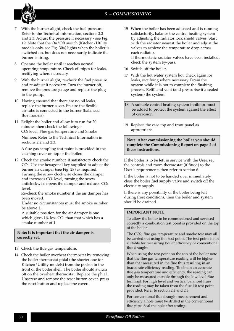
Refer to Figs. 21 or 22 for boiler controls
It is important that the following commissioningprocedure is carried out to ensure safe and efficientoperation of the boiler.If the boiler output is to be adjusted from that whichis factory set, refer to section 1.2 or 1.3 for therequired settings, section 7.4 for burner head/nozzlechange instructions and Fig. 24 for baffleadjustment as appropriate.
Note: Check that the baffles are in position andthat the cleaning cover is correctly fitted and agood seal made.
Combined Boiler/Overheat thermostatof the Boiler House modelsFig 22 - Boiler House models
Fig 21 - Utility models
Note: Boiler House models will start as soon asthe electricity supply to the boiler is switched on.
30 Euroflame Oil Boilers
7 With the burner alight, check the fuel pressure.Refer to the Technical Information, sections 2.2and 2.3. Adjust the pressure if necessary - see Fig.19. Note that the On/Off switch (Kitchen/Utilitymodels only, see Fig. 30a) lights when the boiler isswitched on, but does not necessarily indicate theburner is firing.
8 Operate the boiler until it reaches normaloperating temperature. Check oil pipes for leaks,rectifying where necessary.
9 With the burner alight, re-check the fuel pressureand re-adjust if necessary. Turn the burner off,remove the pressure gauge and replace the plugin the pump.
10 Having ensured that there are no oil leaks,replace the burner cover. Ensure the flexibleair tube is connected to the burner (balancedflue models).
11 Relight the boiler and allow it to run for 20minutes then check the following:-CO2 level, Flue gas temperature and SmokeNumber. Refer to the Technical Information insections 2.2 and 2.3.A flue gas sampling test point is provided in thecleaning cover on top of the boiler.
12 Check the smoke number, if satisfactory check theCO2. Use the hexagonal key supplied to adjust theburner air damper (see Fig. 28) as required.Turning the screw clockwise closes the damperand increases CO2 level, turning the screwanticlockwise opens the damper and reduces CO2
level.Re-check the smoke number if the air damper hasbeen moved.Under no circumstances must the smoke numberbe above 1.A suitable position for the air damper is onewhich gives 1% less CO2 than that which has asmoke number of 1.
13 Check the flue gas temperature.14 Check the boiler overheat thermostat by removing
the boiler thermostat phial (the shorter one forKitchen/Utility models) from the pocket in thefront of the boiler shell. The boiler should switchoff on the overheat thermostat. Replace the phial.Unscrew and remove the reset button cover, pressthe reset button and replace the cover.
15 When the boiler has been adjusted and is runningsatisfactorily, balance the central heating systemby adjusting the radiator lock shield valves. Startwith the radiator nearest the boiler and adjust thevalves to achieve the temperature drop acrosseach radiator.If thermostatic radiator valves have been installed,check the system by-pass.
16 Switch off the boiler.17 With the hot water system hot, check again for
leaks, rectifying where necessary. Drain thesystem while it is hot to complete the flushingprocess. Refill and vent (and pressurise if a sealedsystem) the system.
19 Replace the case top and front panel asappropriate.
If the boiler is to be left in service with the User, setthe controls and room thermostat (if fitted) to theUser’s requirements then refer to section 6.If the boiler is not to be handed over immediately,close the boiler fuel supply valve and switch off theelectricity supply.If there is any possibility of the boiler being leftduring frost conditions, then the boiler and systemshould be drained.
5 – COMMISSIONING
Note: It is important that the air damper iscorrectly set.
18 A suitable central heating system inhibitor mustbe added to protect the system against the effectof corrosion.
Note: After commissioning the boiler you shouldcomplete the Commissioning Report on page 2 ofthese instructions.
IMPORTANT NOTE:To allow the boiler to be commissioned and servicedcorrectly a combustion test point is provided on the topof the boiler.The CO2, flue gas temperature and smoke test may allbe carried out using this test point. The test point is notsuitable for measuring boiler efficiency or conventionalflue draught.When using the test point on the top of the boiler notethat the flue gas temperature reading will be higherthan that measured in the flue thus resulting in aninaccurate efficiency reading. To obtain an accurateflue gas temperature and efficiency, the reading canonly be measured outside through the low level flueterminal. For high level and vertical balanced fluesthe reading may be taken from the flue kit test pointprovided. Refer to section 2.2 and 2.3.For conventional flue draught measurement andefficiency a hole must be drilled in the conventionalflue pipe. Seal the hole after testing.
31Euroflame Oil Boilers
6 - INFORMATION FOR THE USER
The User must be advised (and demonstrated ifnecessary) of the following important points:-
1 How to light and turn off the boiler and how tooperate the system controls.
2 The precautions necessary to prevent damage tothe central heating system and to the building, inthe event of the boiler not being in operationduring frost conditions.
3 The importance of servicing the boiler to ensuresafe and efficient operation. This should normallyonly be required once a year.
4 The type of fuel used.
5 That any servicing or replacement of parts mustonly be carried out by a suitably qualifiedengineer.
6 Ensure that the boiler controls and roomthermostat (if fitted) are set to the User'srequirements.
7 If the boiler is used on a sealed heating system,tell the User the system pressure and show themthe position of the safety valve discharge pipe.
8 Show the User how to reset the overheatthermostat and how to restart the boiler if it goesto 'Lock-out'.
7 - BOILER SERVICING
Leave this Instruction Manual with the User.
To ensure efficient operation of the boiler it isrecommended that it is checked and serviced asnecessary at regular intervals. The frequency ofservicing will depend upon the particular installationconditions and usage, but in general once per yearshould be adequate. Servicing and replacement ofparts must only be carried out by a suitably qualifiedengineer.
1 Check the flue terminal and ensure it is notblocked or damaged.
2 Run the boiler and check the operation of itscontrols
3 Ensure that all water/fuel system connections andfittings are sound. Remake any joints and checkthe tightness of any fittings that may be leaking.If the boiler is used on a sealed central heatingsystem, check the system pressure. Refill, ventand re-pressurise the system as necessary.Check the expansion vessel air charge. See section4.7.
4 Check that any ventilation openings are adequateand are clear. See section 3.6.
5 Remove any sludge/water from the fuel tank byopening the sludge valve at the lower end of thetank.
6 With the fuel supply valve closed, clean/replacethe filter element and clean the filter bowl.
7 Flexible fuel supply pipes should be inspectedannually when the boiler is serviced and replacedevery two years. If in doubt replace the pipes.
The data label on the inside of the case side panel forKitchen/Utility models or on the front panel for BoilerHouse models, will indicate the fuel used and nozzlefitted.
1 Kitchen/Utility models - Remove the boiler frontpanel. Remove the larger of the case top panels(lifts off - four push-on fixings).
2 If necessary, disconnect the flexible air supplytube from the burner.
Important: Details of every service should be entredin the Service Log, on page 2 of these instructions.This information may be required to validate theGrant warranty.
IMPORTANTBefore starting any work on the boiler, or fuel supplyplease read the health and safety information given insection 11 on page 41.
Warning: Before servicing, set the boiler On/Off switchto OFF (Kitchen/Utility models only), isolate theelectricity supply and close the fuel supply valve. Allowthe boiler to cool.
7.1 Important notes prior to servicing
7.2 Dismantling prior to servicing
32 Euroflame Oil Boilers
3 Remove the burner fixing nut (top of mountingflange) and withdraw the burner. If required,disconnect the flexible oil pipe(s), use a suitablecontainer to prevent any oil spillage.
4 Kitchen/Utility models - Carefully remove thetop insulation panel taking care not to damage it.
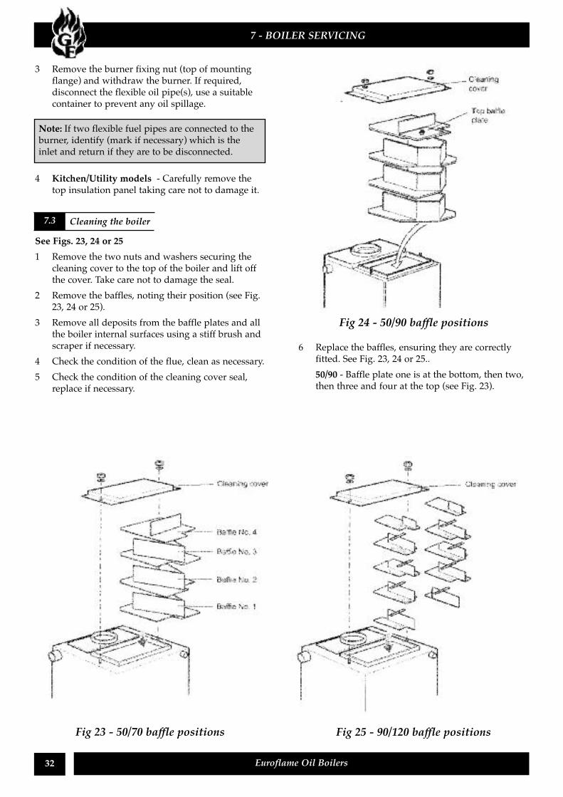
See Figs. 23, 24 or 251 Remove the two nuts and washers securing the
cleaning cover to the top of the boiler and lift offthe cover. Take care not to damage the seal.
2 Remove the baffles, noting their position (see Fig.23, 24 or 25).
3 Remove all deposits from the baffle plates and allthe boiler internal surfaces using a stiff brush andscraper if necessary.
4 Check the condition of the flue, clean as necessary.5 Check the condition of the cleaning cover seal,
replace if necessary.
6 Replace the baffles, ensuring they are correctlyfitted. See Fig. 23, 24 or 25..50/90 - Baffle plate one is at the bottom, then two,then three and four at the top (see Fig. 23).
7 - BOILER SERVICING
Note: If two flexible fuel pipes are connected to theburner, identify (mark if necessary) which is theinlet and return if they are to be disconnected.
7.3 Cleaning the boiler
Fig 23 - 50/70 baffle positions Fig 25 - 90/120 baffle positions
Fig 24 - 50/90 baffle positions
7 Replace the cleaning cover, ensuring the sealis in good condition and secure it in position withthe two nuts and washers previously removed.Tighten to form a seal.
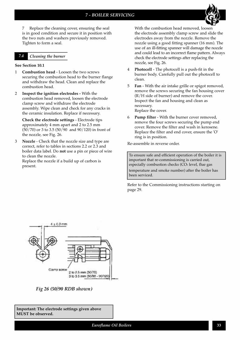
See Section 10.11 Combustion head - Loosen the two screws
securing the combustion head to the burner flangeand withdraw the head. Clean and replace thecombustion head.
2 Inspect the ignition electrodes -With thecombustion head removed, loosen the electrodeclamp screw and withdraw the electrodeassembly. Wipe clean and check for any cracks inthe ceramic insulation. Replace if necessary.Check the electrode settings - Electrode tipsapproximately 4 mm apart and 2 to 2.5 mm(50/70) or 3 to 3.5 (50/90 and 90/120) in front ofthe nozzle, see Fig. 26.
3 Nozzle - Check that the nozzle size and type arecorrect, refer to tables in sections 2.2 or 2.3 andboiler data label. Do not use a pin or piece of wireto clean the nozzle.Replace the nozzle if a build up of carbon ispresent.
With the combustion head removed, loosenthe electrode assembly clamp screw and slide theelectrodes away from the nozzle. Remove thenozzle using a good fitting spanner (16 mm). Theuse of an ill-fitting spanner will damage the nozzleand could lead to an incorrect flame pattern. Alwayscheck the electrode settings after replacing thenozzle, see Fig. 26.
4 Photocell - The photocell is a push-fit in theburner body. Carefully pull out the photocell toclean.
5 Fan - With the air intake grille or spigot removed,remove the screws securing the fan housing cover(R/H side of burner) and remove the cover.Inspect the fan and housing and clean asnecessary.Replace the cover.
6 Pump filter - With the burner cover removed,remove the four screws securing the pump endcover. Remove the filter and wash in kerosene.Replace the filter and end cover, ensure the 'O'ring is in position.
Re-assemble in reverse order.
Refer to the Commissioning instructions starting onpage 29.
33Euroflame Oil Boilers
7 - BOILER SERVICING
7.4 Cleaning the burner
To ensure safe and efficient operation of the boiler it isimportant that re-commissioning is carried out,especially combustion checks (CO2 level, flue gastemperature and smoke number) after the boiler hasbeen serviced.
Fig 26 (50/90 RDB shown)
Important: The electrode settings given aboveMUST be observed.
34 Euroflame Oil Boilers
8 – WIRING DIAGRAMS
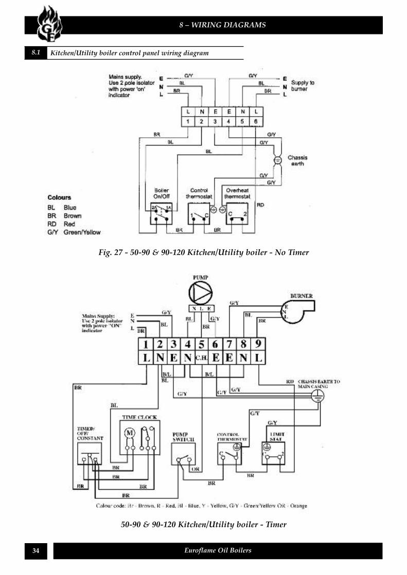
8.1 Kitchen/Utility boiler control panel wiring diagram
Fig. 27 - 50-90 & 90-120 Kitchen/Utility boiler - No Timer
50-90 & 90-120 Kitchen/Utility boiler - Timer
35Euroflame Oil Boilers
8 – WIRING DIAGRAMS
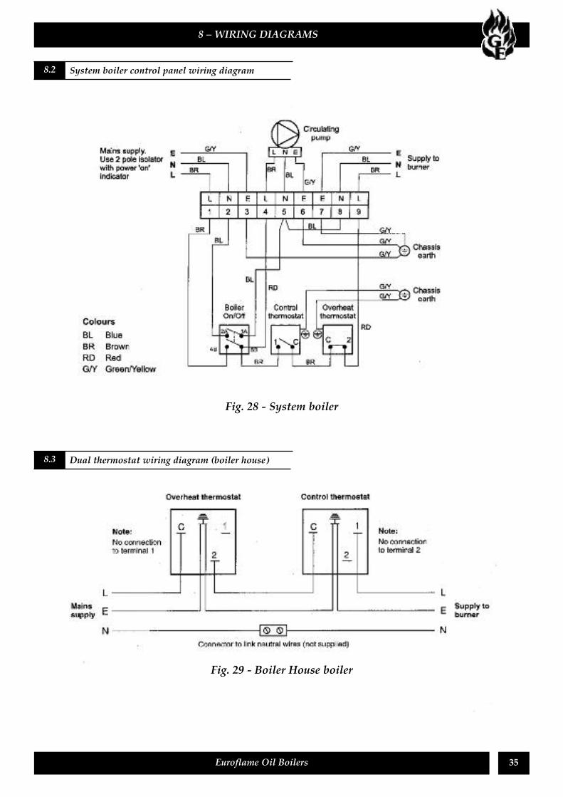
Fig. 28 - System boiler
8.2 System boiler control panel wiring diagram
8.3 Dual thermostat wiring diagram (boiler house)
Fig. 29 - Boiler House boiler
36 Euroflame Oil Boilers
8 – WIRING DIAGRAMS
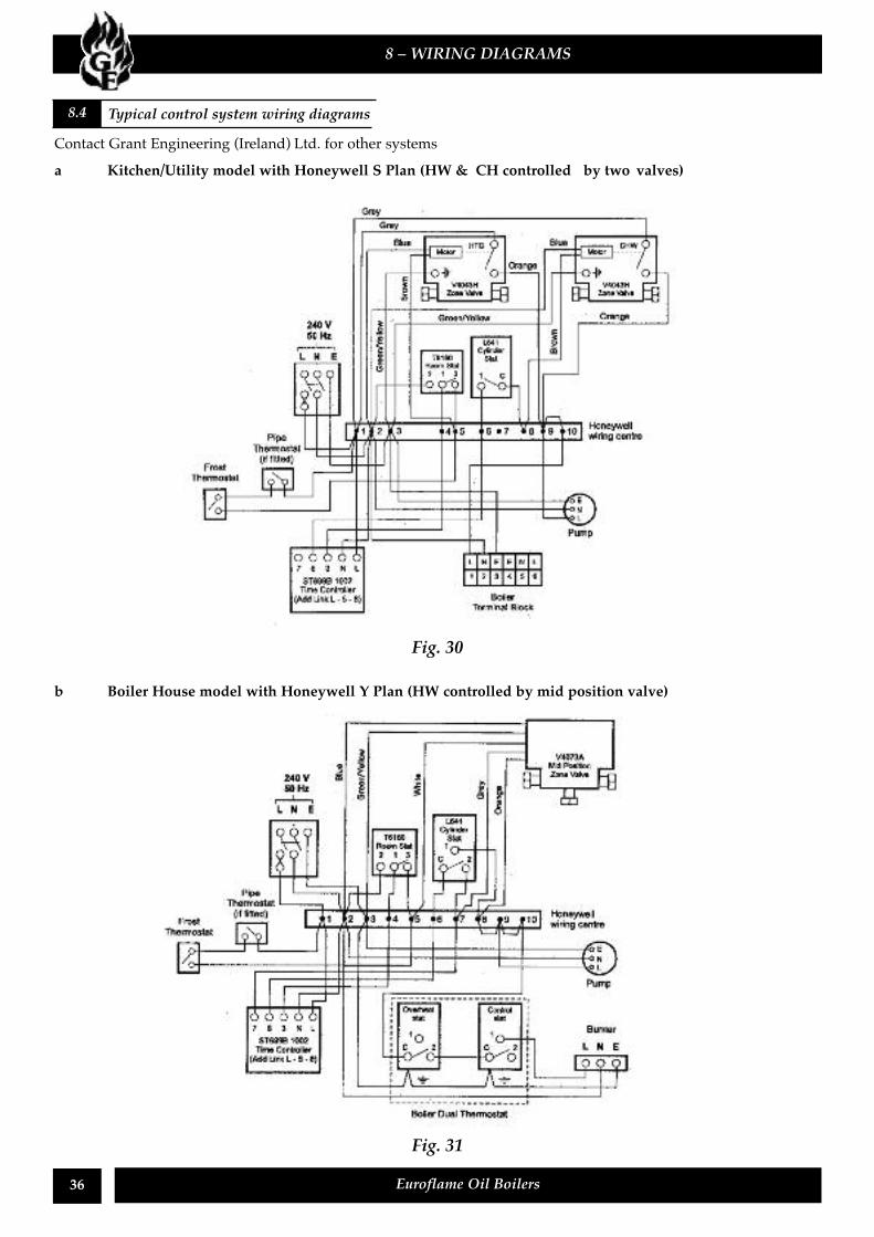
Fig. 31
b Boiler House model with Honeywell Y Plan (HW controlled by mid position valve)
Fig. 30
8.4 Typical control system wiring diagrams
Contact Grant Engineering (Ireland) Ltd. for other systemsa Kitchen/Utility model with Honeywell S Plan (HW & CH controlled by two valves)
37Euroflame Oil Boilers
8 – WIRING DIAGRAMS
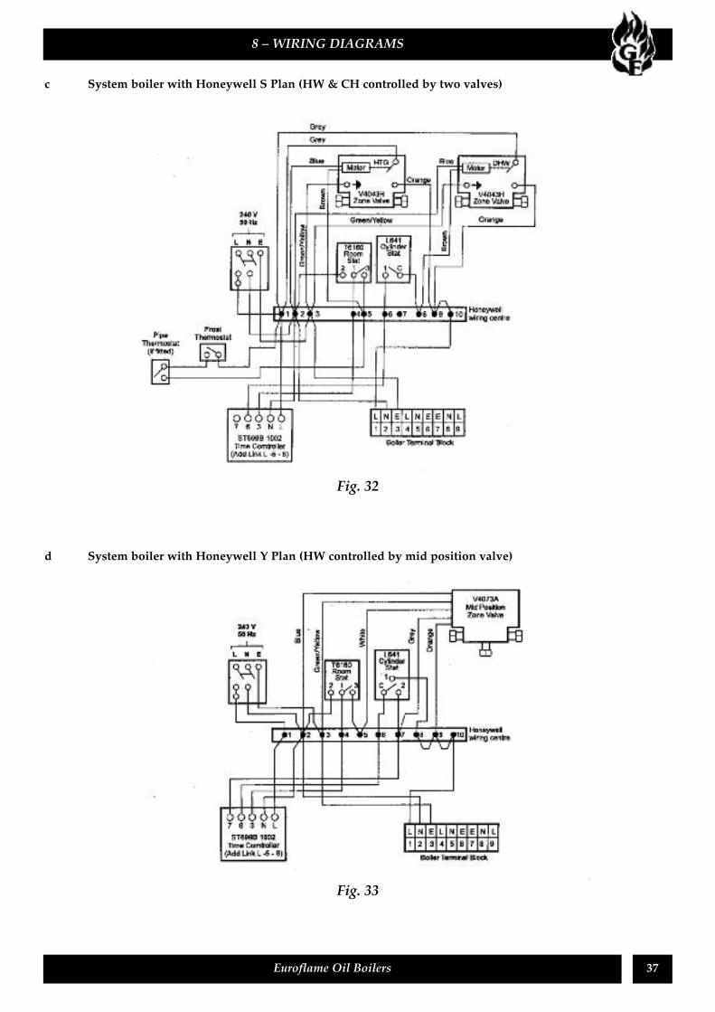
Fig. 32
c System boiler with Honeywell S Plan (HW & CH controlled by two valves)
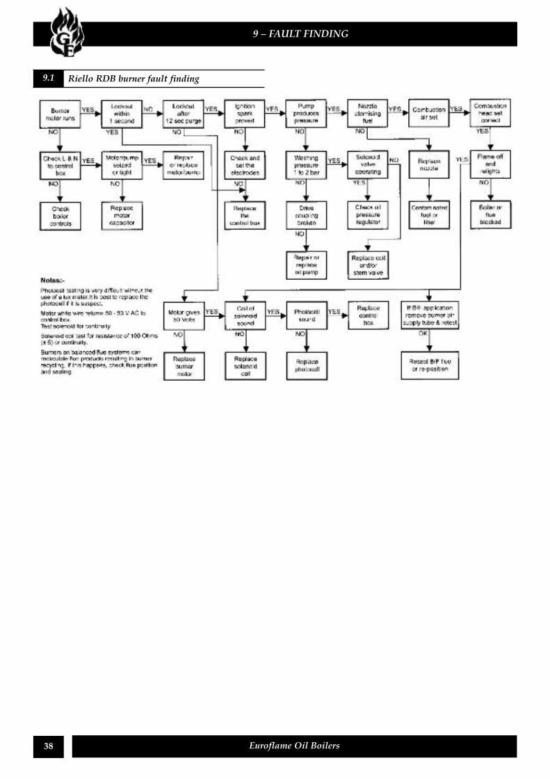
d System boiler with Honeywell Y Plan (HW controlled by mid position valve)
Fig. 33
38 Euroflame Oil Boilers
9 – FAULT FINDING
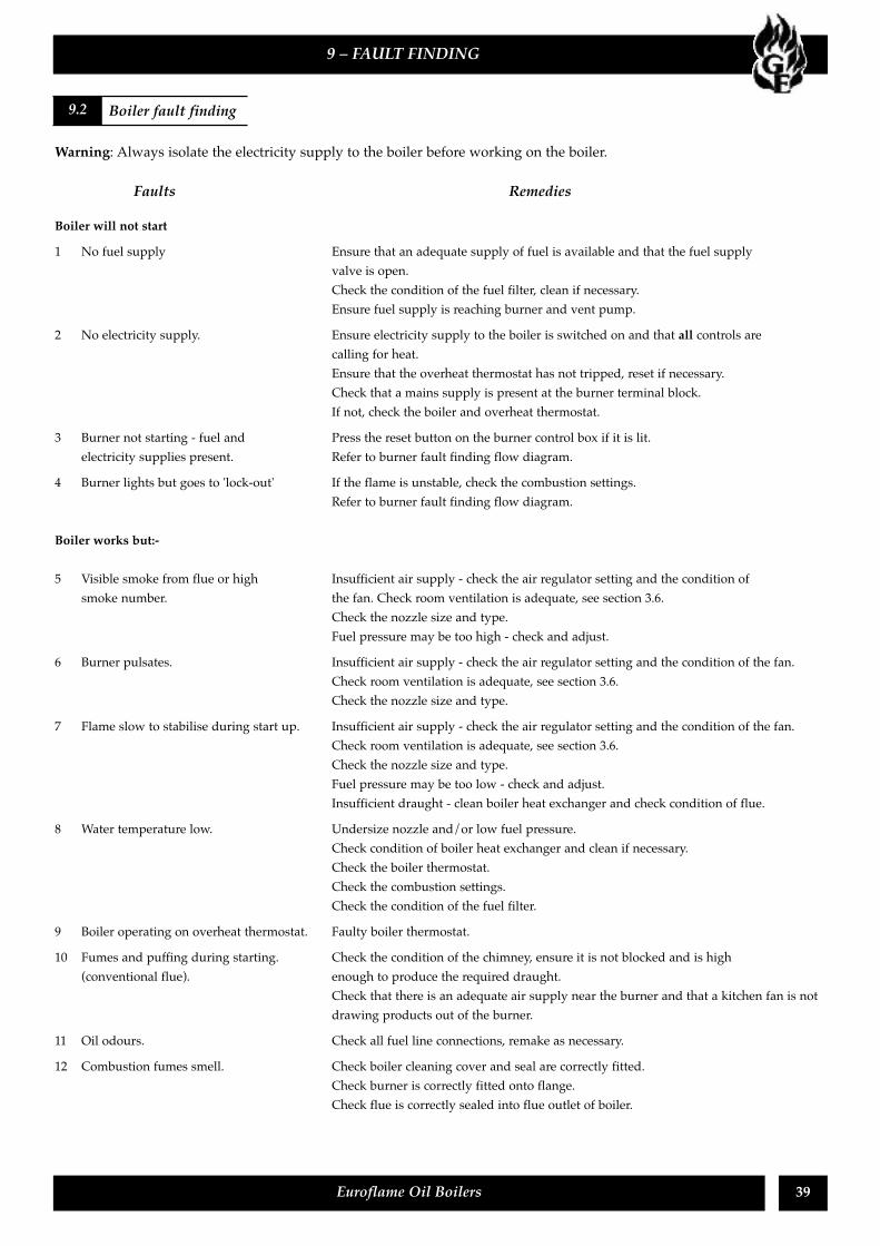
9.1 Riello RDB burner fault finding
39Euroflame Oil Boilers
Warning: Always isolate the electricity supply to the boiler before working on the boiler.
Faults Remedies
Boiler will not start1 No fuel supply Ensure that an adequate supply of fuel is available and that the fuel supply
valve is open.Check the condition of the fuel filter, clean if necessary.Ensure fuel supply is reaching burner and vent pump.
2 No electricity supply. Ensure electricity supply to the boiler is switched on and that all controls arecalling for heat.Ensure that the overheat thermostat has not tripped, reset if necessary.Check that a mains supply is present at the burner terminal block.If not, check the boiler and overheat thermostat.
3 Burner not starting - fuel and Press the reset button on the burner control box if it is lit.electricity supplies present. Refer to burner fault finding flow diagram.
4 Burner lights but goes to 'lock-out' If the flame is unstable, check the combustion settings.Refer to burner fault finding flow diagram.
Boiler works but:-
5 Visible smoke from flue or high Insufficient air supply - check the air regulator setting and the condition ofsmoke number. the fan. Check room ventilation is adequate, see section 3.6.
Check the nozzle size and type.Fuel pressure may be too high - check and adjust.
6 Burner pulsates. Insufficient air supply - check the air regulator setting and the condition of the fan.Check room ventilation is adequate, see section 3.6.Check the nozzle size and type.
7 Flame slow to stabilise during start up. Insufficient air supply - check the air regulator setting and the condition of the fan.Check room ventilation is adequate, see section 3.6.Check the nozzle size and type.Fuel pressure may be too low - check and adjust.Insufficient draught - clean boiler heat exchanger and check condition of flue.
8 Water temperature low. Undersize nozzle and/or low fuel pressure.Check condition of boiler heat exchanger and clean if necessary.Check the boiler thermostat.Check the combustion settings.Check the condition of the fuel filter.
9 Boiler operating on overheat thermostat. Faulty boiler thermostat.10 Fumes and puffing during starting. Check the condition of the chimney, ensure it is not blocked and is high
(conventional flue). enough to produce the required draught.Check that there is an adequate air supply near the burner and that a kitchen fan is notdrawing products out of the burner.
11 Oil odours. Check all fuel line connections, remake as necessary.12 Combustion fumes smell. Check boiler cleaning cover and seal are correctly fitted.
Check burner is correctly fitted onto flange.Check flue is correctly sealed into flue outlet of boiler.
9 – FAULT FINDING
9.2 Boiler fault finding
40 Euroflame Oil Boilers
10 – BURNER SPARE PARTS
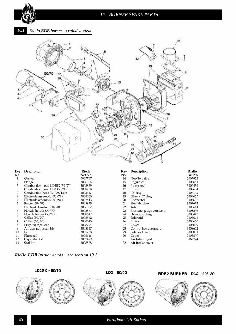
10.1 Riello RDB burner - exploded view
Riello RDB burner heads - see section 10.1
Key Description Riello GrantNo. Part No. Part No.1 Gasket 3005787 RBS1052 Flange 3006384 RBS1103 Combustion head LD2SX (50/70) 3008859 RBS1323 Combustion head LD3 (50/90) 3008768 RBS1273 Combustion head T3 (90/120) 3002447 RBS1444 Electrode assembly (50/70) 3008860 RBS1334 Electrode assembly (50/90) 3007513 RBS1085 Screw (50/70) 3008875 RBS1375 Electrode bracket (50/90) 3006552 RBS296 Nozzle holder (50/70) 3008861 RBS1346 Nozzle holder (50/90) 3008642 RBS1117 Collar (50/70) 3008862 RBS1357 Collar (50/90) 3008643 RBS1128 High voltage lead 3008794 RBS1299 Air damper assembly 3008647 RBS11610 Fan 3005708 RBS3911 Photocell 3008646 RBS11512 Capacitor 4µF 3007479 RBS10713 Seal kit 3008878 RBS140
Key Description Riello GrantNo. Part No. Part No.14 Needle valve 3007852 RBS10915 Regulator 3008651 RBS12016 Pump seal 3000439 RBS1417 Pump 3008654 RBS10118 ‘O’ ring 3007162 RBS0819 Filter - ‘O’ ring 3008653 RBS12220 Connector 3003602 RBS3521 Flexible pipe 3007672 RBS3622 Tube 3008644 RBS11323 Pressure gauge connector 3008876 RBS13824 Drive coupling 3000443 RBS1625 Solenoid 3008648 RBS11726 Motor 3008650 RBS10227 Cover 3008649 RBS11828 Control box assembly 3008652 RBS10329 Solenoid lead 3008851 RBS13930 Cover 3008879 RBS14131 Air tube spigot 3062774 RBS12332 Air intake cover RBS142
LD2SX - 50/70 LD3 - 50/90 RDB2 BURNER LD3A - 90/120
41Euroflame Oil Boilers
11 – HEALTH AND SAFETY INFORMATION
When installing any appliance care should be taken to avoid injury from panel edges or other items associated with theappliance.Under the Consumer Protection Act 1987 and Section 6 of the Health & Safety at Work Act 1974, we are required to provideinformation on substances hazardous to health (COSHH Regulations 1988).Adhesives, sealants and paints used in the manufacture of the product are cured and present no known hazards whenused in the manner for which they are intended.The following other materials are present in the product:
Insulation materialsMaterial Types: Ceramic fibre board, mineral wool.Description: Rigid board, slabs, sleeves, gaskets, ropes.Known Hazards: May cause temporary irritation or rash to skin. High dust levels may irritate eyes and upper
respiratory system.Precautions: Avoid unnecessary or rough handling, or harsh abrasion of boards. Normal handling and use of
material should not produce high dust levels.Avoid inhalation, and contact with skin and eyes.After handling always follow normal good hygiene practices.
Protection: Use disposable gloves, face mask and eye protection.First Aid: Eyes – If irritation occurs, wash eyes with copious amounts of water. If symptoms persist, seek
immediate medical advice.Skin – If irritation occurs, wash under running water before washing with soap and water.Inhalation – Remove to fresh air, drink water to clear throat and blow nose to removedust/fibres.Ingestion – Drink plenty of water.
SealantsMaterial Types: Silicone elastomer.Description: Sealant and adhesive.Known Hazards: Irritation to eyes.Precautions: Avoid inhalation of vapour, contact with eyes and prolonged or repeated contact with skin.
After handling always follow normal good hygiene practices.Protection: Use eye protection. Rubber or plastic gloves should be worn where repeated contact occurs and
a face mask worn when working in confined spaces.First Aid: Eyes – Flush eyes with water for 15 minutes. Seek immediate medical attention.
Skin – Wipe off and wash with soap and water.Inhalation – Remove to fresh air.
Kerosene and Gas oil fuels (Mineral oils)Known Hazards: The effect of mineral oils on the skin vary according to the duration of exposure and the type of
oilThe lighter fractions remove the protective grease naturally present on the skin, leaving it dry,liable to crack and more prone to damage by cuts, abrasions and irritant chemicals.Skin rashes (Oil acne) most often on arms, but also on any part of the body in contact with oil oroily clothing.Contact with fuel oils can cause dermatitis.
Precautions: Avoid as far as possible any skin contact with mineral oil or with clothing contaminated withmineral oil.The use of lanolin-based barrier cream is recommended, in conjunction with regular washingwith soap and rinsing with water to ensure all oil is removed from the skin.Take care to prevent clothing, especially underwear, from becoming contaminated with oil.Do not put oily rags or tools in pockets, especially trouser pockets.Have first-aid treatment at once for an injury, however slight.Do not inhale any vapours from mineral oils.

42 Euroflame Oil Boilers

43Euroflame Oil Boilers
We declare that the Euroflame range of Oil Boilers equipped with Riello RDB burner approved to EN 267: 1991satisfy the requirements of the following European Directives:
1. 89/336/EEC - Electromagnetic Compatibility DirectiveReferred to the generic standards EN 55014 : 1993 EN 50082 - 1 - 1992
2. 73/23/EEC - Electrical Equipment Safety Regulations DirectiveReferred to the generic standard No: 3260: The Electrical Equipment (Safety) Regulations: 1994
3. 92/42/EEC - Hot Water Boiler Efficiency DirectiveReferred to the generic standard - The Boiler (Efficiency) (Amendment) Regulations 1994(SI 1994/3083)
Signed:__________________________________
Managing DirectorGrant Engineering (Ireland) Ltd.,Crinkle, Birr, Co. Offaly, Ireland.
––––––––––––––––––––––––––––––––––––––––––––––––––––––––
TERMS OF GUARANTEE1. The company shall mean Grant Engineering (Ireland) Limited.2. The Boiler is guaranteed for a period of 12 months from the date of installation providing that any work
undertaken is authorised by the company and carried out by an approved service agent.3. The shell (heat-exchanger) of oil boilers supplied by Grant Engineering (Ireland) Limited are
guaranteed for a period of 5 years from the date of installation. All other boiler components, excludingconsumables (such as nozzles and filters), for 1 year from the date of installataion.
4. This guarantee does not cover breakdowns caused by incorrect installation, neglect, misuse, accident orfailure to operate this boiler in accordance with the manufacturers instructions.
5. This guarantee is not transferable unless sanctioned by the Company.6. The Company will endeavour to provide prompt service in the unlikely event of a problem occurring,
but cannot be held responsible for any consequence of delay however caused.7. This guarantee does not cover labour, handling or shipping.8. This guarantee applies to boilers installed on the island of Ireland both North and South. Provision of
the warranty cover elsewhere is subject to agreement with Grant Engineering (Ireland) Ltd.
44 Euroflame Oil Boilers
12 – EC DECLARATION OF CONFORMITY
GRANT ENGINEERING (IRELAND) LTD.,CRINKLE, BIRR, CO. OFFALY.
Telephone: (057) 9120352/9120089This manual is accurate at the date of printing but will be superseded and should bedisregarded if specifications and/or appearances are changed in the interests of continuedproduct improvement.All goods sold are subject to our official Conditions of Sale, a copy of which may be obtainedon application.© Grant Engineering (Ireland) Limited 2001. No part of this manual may be reproduced by anymeans without prior written consent.
GRANTENGINEERING LTD. 1169C