Embed Size (px)
Citation preview

European Aviation Safety Agency
Notice of Proposed Amendment 2016-04
TE.RPRO.00034-004 © European Aviation Safety Agency. All rights reserved. ISO 9001 certified. Proprietary document. Copies are not controlled. Confirm revision status through the EASA intranet/internet. Page 1 of 196
An agency o the European Union
Maintaining aerodrome rules
CS ADR-DSN — Issue 3 RMT.0591 — 14.6.2016
EXECUTIVE SUMMARY
The objective of this amendment is to update the certification specifications for aerodromes design in line with the ICAO developments and other technical improvements, and to maintain a high level of safety of aerodrome design. The Agency is proposing this re-issue of CS ADR-DSN in order to support and facilitate the aerodrome operators and airport industry together with the respective competent authorities that are currently performing a certification process following Commission Regulation (EU) No 139/2014. This certification process would need to take into account the envisaged changes.
The purpose of this amendment is to update the certification specifications (CSs) and guidance material (GM) for Aerodrome Design (CS-ADR-DSN — CS Issue 2) mainly in accordance with the respective ICAO standards and recommended practices (SARPs), incorporated in ICAO State Letter AN 4/1.2.24-13/20 which includes Amendments 11-A and 11-B to ICAO Annex 14, Volume I, Aerodromes. Amendment 11-A includes updates on some definitions, as for example: hot spot, instrument runway and non-instrument runway, characteristics of surface of runways and of runway turn pads, objects on runway strips, blast pad, runway end safety areas, surface of stopways and of taxiways, enhanced taxiway centre line marking, simple touchdown zone lights, alternate taxiway centre line lights, stop bars, runway guard lights, no-entry bar, etc. This amendment incorporates reformatting of Chapter 6 of Annex 14 ‘Visual aids for denoting obstacles’, as well as siting of equipment and installations on operational areas, runway pavement overlays and visual aids, including light emitting diodes (LEDs), colours for aeronautical ground lights, markings, signs and panels, including white colour for LED lights, aeronautical ground light characteristics, including no-entry bar, integrity classifications, as well characteristics of movement area and adjacent areas and runway end safety areas. Amendment 11-B concerns revised instrument and non-instrument approach runway definitions as a result of new approach classification definitions. This amendment also includes new requirements for the runway starter extension which is already in use in some member States, but not with harmonised requirements at EU level. Runway starter extension may be used for runways where additional distance is required for take-off.
This amendment also addresses some recommendations and comments received from stakeholders, and it encompasses corrections and some administrative changes for better clarity of the text, unification of references, etc. However, this amendment does not contain ICAO Amendments 12 and 13 to Annex 14, some technical proposals received in the meantime from stakeholders and individuals, and some other updates of the guidance material. They will be incorporated in the NPA for CS ADR-DSN Issue 4, which is foreseen for Q1/2017.
The changes to the design characteristics emerging from this amendment are of major significance to the aerodrome industry also in an economic sense and, besides the facilitating effect along the now on-going certification exercise, do provide better clarity and consistency with international standards. Additionally, this revision will enable aerodrome operators to further develop their facilities within the existing infrastructure or future aerodrome extensions and to reduce the overall costs.
Applicability Process map
Affected regulations and decisions:
Regulation (EU) No 139/2014
ED Decision 2015/001/R.’CS-ADR-DSN — Issue 2’
Concept Paper:
Terms of Reference:
Rulemaking group:
RIA type:
Technical consultation
during NPA drafting:
Duration of NPA consultation:
Review group:
Focused consultation:
Publication date of the Decision:
No
10.4.2014
No
None
Yes
1 month
TBD
Yes
Q3/2016
Affected stakeholders:
Aerodrome operators,
National Aviation Authorities
Driver/origin: Efficiency/Proportionality
Reference: N/A

European Aviation Safety Agency NPA 2016-04
Table of contents
TE.RPRO.00034-004 © European Aviation Safety Agency. All rights reserved. ISO 9001 certified. Proprietary document. Copies are not controlled. Confirm revision status through the EASA intranet/internet. Page 2 of 196
An agency of the European Union
Table of contents
1. Procedural information .............................................................................................................................. 4 The rule development procedure...................................................................................................... 4 1.1. The structure of this NPA and related documents ............................................................................ 4 1.2. How to comment on this NPA ........................................................................................................... 4 1.3. The next steps in the procedure ........................................................................................................ 4 1.4.
2. Explanatory Note ........................................................................................................................................ 5 Overview of the issues to be addressed ............................................................................................ 5 2.1. Objectives .......................................................................................................................................... 8 2.2. Regulatory Impact Assessment (RIA)................................................................................................. 8 2.3. Overview of the proposed amendments for CS ADR-DSN Issue 3 .................................................... 8 2.4.
3. Proposed amendments ............................................................................................................................ 41 Draft Certification Specifications ..................................................................................................... 41 3.1.
4. References .............................................................................................................................................. 196 Affected regulations ...................................................................................................................... 196 4.1. Affected decision ........................................................................................................................... 196 4.2. Reference documents.................................................................................................................... 196 4.3.
5. Appendices ............................................................................................................................................. 197

European Aviation Safety Agency NPA 2016-04
1. Procedural information
TE.RPRO.00034-004 © European Aviation Safety Agency. All rights reserved. ISO 9001 certified. Proprietary document. Copies are not controlled. Confirm revision status through the EASA intranet/internet. Page 4 of 196
An agency of the European Union
1. Procedural information
The rule development procedure 1.1.
The European Aviation Safety Agency (hereinafter referred to as the ‘Agency’) developed this Notice of
Proposed Amendment (NPA) in line with Regulation (EC) No 216/20081 (hereinafter referred to as the
‘Basic Regulation’) and the Rulemaking Procedure2.
This rulemaking activity is included in the Agency’s 5-year Rulemaking Programme under RMT.0591
‘Maintaining aerodromes rules’.
The text of this NPA has been developed by the Agency, based on the input of the stakeholders via
surveys and thematic meetings consultations. It is hereby submitted for consultation of all interested
parties3.
The process map on the title page contains the major milestones of this rulemaking activity to date and
provides an outlook of the timescale of the next steps.
The structure of this NPA and related documents 1.2.
Chapter 1 of this NPA contains the procedural information related to this task. Chapter 2 (Explanatory
Note) explains the core technical content. Chapter 3 contains the proposed text for the amendment of
CS ADR-DSN — Issue 2. This NPA does not require a regulatory impact assessment (RIA).
How to comment on this NPA 1.3.
Please submit your comments using the automated Comment-Response Tool (CRT) available at
http://hub.easa.europa.eu/crt/4.
The deadline for submission of comments is 14 July 2016.
The next steps in the procedure 1.4.
Following the closing of the NPA public consultation period, the Agency will review all comments. The
outcome of this consultation will be reflected in a comment-response document (CRD) which the
Agency will publish together with the Decision amending certification specifications (CS) and guidance
material (GM) for aerodrome design, CS-ADR-DSN — Issue 3.
1 Regulation (EC) No 216/2008 of the European Parliament and the Council of 20 February 2008 on common rules in the field of civil
aviation and establishing a European Aviation Safety Agency, and repealing Council Directive 91/670/EEC, Regulation (EC) No 1592/2002 and Directive 2004/36/EC (OJ L 79, 19.3.2008, p. 1), as last amended by Commission Regulation (EU) No 6/2013 of 8 January 2013 (OJ L 4, 9.1.2013, p. 34).
2 EASA is bound to follow a structured rulemaking process as required by Article 52(1) of the Basic Regulation. Such process has been
adopted by the EASA Management Board (MB) and is referred to as the ‘Rulemaking Procedure’. See MB Decision No 18-2015 of 15 December 2015 replacing Decision 01/2012 concerning the procedure to be applied by the Agency for the issuing of opinions, certification specifications and guidance material (‘Rulemaking Procedure’).
3 In accordance with Article 52 of the Basic Regulation and Articles 6(3) and 7 of the Rulemaking Procedure.
4 In case of technical problems, please contact the CRT webmaster ([email protected]).

European Aviation Safety Agency NPA 2016-04
2. Explanatory Note
TE.RPRO.00034-004 © European Aviation Safety Agency. All rights reserved. ISO 9001 certified. Proprietary document. Copies are not controlled. Confirm revision status through the EASA intranet/internet. Page 5 of 196
An agency of the European Union
2. Explanatory Note
Overview of the issues to be addressed 2.1.
CS ADR-DSN.A.002 Definitions
The Agency is proposing an update of the definitions on instrument/non-instrument ‘approach
runways’ in line with ICAO developments and incorporating some other definitions, such as
‘aerodrome traffic density’, ‘apron service road’, ‘hot spot’. Definitions, which are not used in CS ADR-
DSN are proposed to be deleted and also some typos are corrected.
CS ADR-DSN.B.055 Minimum distance between parallel instrument runways
CS ADR-DSN.B.090 Surface of runways
CS ADR-DSN.B.110 Surface of runway turn pads
CS ADR-DSN.B.165 Objects on runway strips
The proposed amendment of paragraph (b) is in line with Amendment 11 A & B of Annex 14, Volume I,
Aerodromes (Amendment 11) for the better clarification of the requirement. The Agency is proposing
the update of the particular CS and GM in order to leave more flexibility for the aerodrome operators
to comply with the requirement.
CS ADR-DSN.B.191 Drainage characteristics of the movement area and adjacent areas
CS ADR-DSN.B.200 Stopways
CS ADR-DSN.B.210 Runway end safety areas (RESA)
The proposed change for runway end safety area (RESA) at visual runways and the associated length
requirements, may, in certain cases, have a varying impact on aerodromes, which, however, is
considered to be outweighed by the clear safety benefit associated by the introduction of the
particular design feature.
CS ADR-DSN.B.215 Dimensions of runway end safety areas
Amendment 11 provides a requirement that a runway end safety area should extend from the end of a
runway strip to a distance of 30 m where the code number is 1 or 2 and the runway is a non-
instrument one.
CS ADR-DSN.B.235 Strength of runway end safety areas
CS ADR-DSN.C.236 Runway starter extension physical characteristics
This amendment also includes newly developed requirements for the runway starter extension which
may be used for runways where additional distance is required for take-off.
CS ADR-DSN.C.237 Runway starter extension shoulders
CS ADR-DSN.C.238 Runway starter extension strip
CS ADR-DSN.D.290 Surface of taxiways
CS ADR-DSN.D.335 Holding bays, runway-holding positions, intermediate holding positions, and
road-holding positions

European Aviation Safety Agency NPA 2016-04
2. Explanatory Note
TE.RPRO.00034-004 © European Aviation Safety Agency. All rights reserved. ISO 9001 certified. Proprietary document. Copies are not controlled. Confirm revision status through the EASA intranet/internet. Page 6 of 196
An agency of the European Union
CS ADR-DSN.D.340 Location of holding bays, runway-holding positions, intermediate holding
positions, and road-holding positions
Better clarification is needed for the possibility of infringement of obstacle limitation surfaces or
interference with the operation of radio navigation aids.
CS ADR-DSN.E.360 Slopes on aprons
CS ADR-DSN.E.365 Clearance distances on aircraft stands
The term ‘using the stand’ is changed with ‘entering or exiting the stand’ for better clarification,
indicating that the aircraft are in motion and not stationary.
CS ADR-DSN.H.420 Inner horizontal surface
CS ADR-DSN.H.445 Obstacle free zone (OFZ)
CS ADR-DSN.J.470 Non-instrument runways
CS ADR-DSN.J.475 Non-precision approach runways
CS ADR-DSN.J.480 Precision approach runways
CS ADR-DSN.J.485 Runways meant for take-off
CS ADR-DSN.J.487 Objects outside the obstacle limitation surfaces
CS ADR-DSN.L.567 Marking of runway starter extension
CS ADR-DSN.L.570 Enhanced taxiway centre line marking
CS ADR-DSN.L.575 Runway-holding position marking
CS ADR-DSN.L.580 Intermediate holding position marking
CS ADR-DSN.L.585 VOR aerodrome checkpoint marking
CS ADR-DSN.L.597 Apron service road marking
CS ADR-DSN.L.600 Road-holding position marking
CS ADR-DSN.L.605 Mandatory instruction marking
CS ADR-DSN.M.615 General
CS ADR-DSN.M.625 Approach lighting systems
CS ADR-DSN.M.630 Precision approach Category I lighting system
CS ADR-DSN.M.635 Precision approach Category II and III lighting system
CS ADR-DSN.M.645 Precision approach path indicator and Abbreviated precision approach path
indicator (PAPI and APAPI)
CS ADR-DSN.M.650 Approach slope and elevation setting of light units for PAPI and APAPI
CS ADR-DSN.M.675 Runway edge lights
CS ADR-DSN.M.680 Runway threshold and wing bar lights
CS ADR-DSN.M.685 Runway end lights

European Aviation Safety Agency NPA 2016-04
2. Explanatory Note
TE.RPRO.00034-004 © European Aviation Safety Agency. All rights reserved. ISO 9001 certified. Proprietary document. Copies are not controlled. Confirm revision status through the EASA intranet/internet. Page 7 of 196
An agency of the European Union
CS ADR-DSN.M.690 Runway centre line lights
CS ADR-DSN.M.695 Runway touchdown zone lights
CS ADR-DSN.M.696 Simple touchdown zone lights
CS ADR-DSN.M.705 Stopway lights
CS ADR-DSN.M.710 Taxiway centre line lights
CS ADR-DSN.M.715 Taxiway centre line lights on taxiways, runways, rapid exit taxiways, or on other
exit taxiways
CS ADR-DSN.M.720 Taxiway edge lights
CS ADR-DSN.M.725 Runway turn pad lights
CS ADR-DSN.M.727 Lights of the runway starter extension
CS ADR-DSN.M.730 Stop bars
CS ADR-DSN.M.735 Intermediate holding position lights
CS ADR-DSN.M.740 De-icing/anti-icing facility exit lights
CS ADR-DSN.M.745 Runway guard lights
CS ADR-DSN.M.750 Apron floodlighting
CS ADR-DSN.M.760 Advanced visual docking guidance system
CS ADR-DSN.M.770 Road-holding position light
CS ADR-DSN.M.771 No-entry bar
CS ADR-DSN.N.775 General
CS ADR-DSN.N.785 Information signs
CS ADR-DSN.Q.840 Objects to be marked and/or lighted within the lateral boundaries of the
obstacle limitation surfaces
CS ADR-DSN.Q.841 Objects to be marked and/or lighted outside the lateral boundaries of the
obstacle limitation surfaces
CS ADR-DSN.Q.845 Marking of fixed objects
CS ADR-DSN.Q.846 Lighting of fixed objects
CS ADR-DSN.Q.847 Lighting of fixed objects with a height less than 45 m above ground level
CS ADR-DSN.Q.848 Lighting of fixed objects with a height 45 m to a height less than 150 m above
ground level
CS ADR-DSN.Q.849 Lighting of fixed objects with a height 150 m or more above ground level
CS ADR-DSN.Q.850 Lighting of other objects
CS ADR-DSN.Q.851 Marking and lighting of wind turbines
CS ADR-DSN.Q.852 Marking and lighting of overhead wires, cables, supporting towers, etc.

European Aviation Safety Agency NPA 2016-04
2. Explanatory Note
TE.RPRO.00034-004 © European Aviation Safety Agency. All rights reserved. ISO 9001 certified. Proprietary document. Copies are not controlled. Confirm revision status through the EASA intranet/internet. Page 8 of 196
An agency of the European Union
CS ADR-DSN.R.855 Closed runways and taxiways, or parts thereof
CS ADR-DSN.S.880 Electrical power supply systems
CS ADR-DSN.S.890 Monitoring
CS ADR-DSN.T.900 Emergency access and service roads
CS ADR-DSN.T.915 Siting of equipment and installations on operational areas
CS ADR-DSN.U.930 Colours for aeronautical ground lights
CS ADR-DSN.U.940 Aeronautical ground light characteristics
Objectives 2.2.
The overall objectives of the EASA system are defined in Article 2 of the Basic Regulation. This proposal
will contribute to the achievement of the overall objectives by addressing the issues outlined in
Chapter 2 of this NPA.
The specific objective of this amendment is to propose an update of certification specifications for
aerodrome design (CS ADR-DSN). The changes are mainly based on ICAO Amendment 11 A & B to
Annex 14, Aerodromes, Volume I and addressing some comments and proposals on safety aspects and
to incorporate a selection of non-complex, non-controversial, and mature subjects. The ultimate goal is
to increase safety.
Regulatory Impact Assessment (RIA) 2.3.
N/A
This NPA does not create new requirements for applicants. Some new or updated requirements that
are proposed are mainly based on the already adopted ICAO Amendment 11 A & B to Annex 14,
Volume I, Aerodromes or are for the benefit of aerodrome operators, for example runway starter
extension, as well as some clarifications of existing certification specifications. Also some missing or
wrong cross references and typos are corrected.
Overview of the proposed amendments for CS ADR-DSN Issue 3 2.4.
The proposal will ensure that CS ADR-DSN — Issue 3 reflects the state of the art and provides better
harmonisation with ICAO. The ICAO State Letter with the amendments to Annex 14, which are
incorporated in this NPA contains a considerable number of proposed changes and additions to the
existing CS ADR-DSN Issue 2 provisions. The proposed amendments serve the general objective of
enhancing aerodrome safety and efficiency.
CS ADR-DSN.A.002 Definitions
The Agency is proposing an update of the definitions on instrument/non-instrument ‘approach
runways’ in line with ICAO developments. The former categorisation of runways on ‘non-instrument’,
‘non-precision’ and ‘precision’ approach runways was based on the type of the approach procedure.
During recent years, the technological advancements in the field of on-board aircraft systems as well as
the use of satellite navigation rendered the execution of approach procedures with vertical guidance

European Aviation Safety Agency NPA 2016-04
2. Explanatory Note
TE.RPRO.00034-004 © European Aviation Safety Agency. All rights reserved. ISO 9001 certified. Proprietary document. Copies are not controlled. Confirm revision status through the EASA intranet/internet. Page 9 of 196
An agency of the European Union
possible without solely depending on ground navigation aids. The former definitions, due to the fact
that they are associated with specific navigational aids, do not allow new concepts to be implemented.
For this reason, ICAO proposed revised definitions for the different types of runways. The new
definitions disassociate the type of the runway from the navigational aids used and consider only the
method used to fly the approach procedure as well as the decision altitude/decision height (DA/DH)
associated with that procedure. The proposed changes allows approach procedures with vertical
guidance to be executed at non-precision runways above a specific DA/DH without the need to
upgrade the runway infrastructure or to impose additional restrictions on the obstacle limitation
surfaces. Similarly, non-instrument runways can use instrument approach procedures up to a point
where the approach procedure will continue under visual meteorological conditions (VMC).
The new definitions are expected to provide significant benefits mainly to aerodromes having non-
instrument or non-precision approach runways, both in terms of safety and accessibility, especially
where operations are impaired by weather conditions or difficult surroundings. For non-instrument
runways, the use of instrument approach procedures up to a point where an approach procedure
continues under VMC ensures that a significant portion of the approach is flown safer under
instrument flight rules (IFR), even at deteriorating weather conditions. For non-precision approach
runways, approach procedures using vertical guidance are considered safer than approach procedures
using lateral guidance only, allowing also lower DA/DH.
The ICAO new approach classification is applicable as of November 2014. There is an urgent need to
include these revised definitions in Regulation (EU) No 139/2014 to allow the aerodrome operators to
benefit from the new concept and to facilitate Member States in the certification process of
aerodromes. The process of amending Regulation (EU) No 139/2014 is currently ongoing.
The Agency also received requests from Member States as well as industry stakeholders to proceed as
soon as possible with the adoption of the new definitions in order to facilitate the ongoing aerodrome
certification and the implementation of PBN approach operations with vertical guidance. Considering
the fact that the issue is not controversial, as already discussed and already applicable at ICAO level,
the Agency already developed an opinion to amend the definitions of ‘instrument’ and ‘non-
instrument’ runway. The identical changes on the definitions are incorporated in this amendment,
draft 'CS ADR-DSN — Issue 3’, and have been already consulted with the Advisory Bodies.
New definitions on ‘Aerodrome traffic density’, ‘Apron service road’ and ‘Hot spot’ are added to the list
of definitions for the better interpretation of some CS provisions. The definitions, which are not used in
CS ADR-DSN are proposed to be deleted and also some corrections of typos are provided.
GM1 ADR-DSN.A.002 Definitions
Additional information is given to the changes and implementation of new approach classifications.
CS ADR-DSN.A.005 Aerodrome reference code
Corrections of typos are provided.
GM1 ADR-DSN.A.005 Aerodrome reference code

European Aviation Safety Agency NPA 2016-04
2. Explanatory Note
TE.RPRO.00034-004 © European Aviation Safety Agency. All rights reserved. ISO 9001 certified. Proprietary document. Copies are not controlled. Confirm revision status through the EASA intranet/internet. Page 10 of 196
An agency of the European Union
‘Aircraft’ is changed with ‘aeroplane’ for better clarification, new paragraph (f) is provided for the
reference to ICAO documents and some corrections of typos are provided.
CS ADR-DSN.A.010
Corrections of typos are provided.
GM1 ADR-DSN.A.010
Corrections of typos are provided.
GM1 ADR-DSN.B.015 Number, siting and orientation of runways
Corrections to reference and typos are provided.
CS ADR-DSN.B.020 Choice of maximum permissible crosswind components
Corrections of typos are provided.
CS ADR-DSN.B.025 Data to be used
Corrections of typos are provided.
CS ADR-DSN.B.035 Length of runway and declared distances
Correction of the title is provided for better clarification.
GM1 ADR-DSN.B.035 Length of runway and declared distances
Corrections of title and typos are provided.
GM1 ADR-DSN.B.045 Width of runways
Corrections of typos are provided.
CS ADR-DSN.B.055 Minimum distance between parallel instrument runways
The possibility for decreasing the distance by 30 m for each 150 m for segregated parallel operations
that the arrival runway is staggered toward the arriving aircraft, to a minimum of 300 m is an option
and not the requirement, so the term ‘should’ is changed with ‘may’ for better clarification of the
requirement.
GM1 ADR-DSN.B.055 Minimum distance between parallel instrument runways
References to different ICAO documents are provided. The proposed change is also in line with ICAO
Annex 14.

European Aviation Safety Agency NPA 2016-04
2. Explanatory Note
TE.RPRO.00034-004 © European Aviation Safety Agency. All rights reserved. ISO 9001 certified. Proprietary document. Copies are not controlled. Confirm revision status through the EASA intranet/internet. Page 11 of 196
An agency of the European Union
CS ADR-DSN.B.060 Longitudinal slopes of runways
Corrections of typos are provided.
GM1 ADR-DSN.B.070 Sight distance for slopes of runways
Correction to the title is provided.
GM1 ADR-DSN.B.080 Transverse slopes on runways
Corrections of typos are provided.
GM1 ADR-DSN.B.085 Runway strength
Paragraph (d) and (e) are deleted, because they are purely operational and already contained in Part-
ADR.OPS.
CS ADR-DSN.B.090 Surface of runways
The proposed amendment of paragraph (a) and (b) is identical to ICAO Annex 14 (Amendment 11) and
is provided for better clarification of the requirements. The reference to ‘good’ friction
characteristics…’ is replaced with ‘surface friction characteristics at or above the minimum friction
level’, as defined in Part-ADR.OPS, Table 1, which will be kept until further agreed. In paragraph (d) the
term ‘If’ is changed with ‘When’ for better clarification.
GM1 ADR-DSN.B.090 Surface of runways
Reference is made to ‘good engineering practice’, also included in Annex 14, Attachment A. A new
paragraph (c) gives additional reference to ICAO manuals, while paragraph (d) is referring to
macrotexture and microtexture, which should be taken into consideration in order to provide the
required surface friction characteristics. Reference is also given to ICAO Doc 9157 for additional
information.
The title ‘SECTION 1 – RUNWAYS TURN PADS’ is deleted in both Book 1 and Book 2 since better
paragraph arrangements are provided and there is no need for additional paragraphs for sections.
‘Chapter B’ consists of requirements for runway physical characteristics, including requirements for
runway end safety area, which were before under ‘Chapter C’. A new ‘Chapter C’ is providing
requirements for the new term ‘runway starter extension’.
GM1 ADR-DSN.B.095 Runway turn pads
Corrections of typos are provided.

European Aviation Safety Agency NPA 2016-04
2. Explanatory Note
TE.RPRO.00034-004 © European Aviation Safety Agency. All rights reserved. ISO 9001 certified. Proprietary document. Copies are not controlled. Confirm revision status through the EASA intranet/internet. Page 12 of 196
An agency of the European Union
GM1 ADR-DSN.B.105 Strength of runway turn pads
Corrections of typos are provided.
CS ADR-DSN.B.110 Surface of runway turn pads
The proposed amendment of the CS is identical to ICAO Annex 14 (Amendment 11), the text is updated
for better clarification, but the meaning remains the same.
GM1 ADR-DSN.B.110 Surface of runway turn pads
Corrections of typos are provided.
GM1 ADR-DSN.B.120 Strength of shoulders for runway turn pads
Corrections of typos are provided.
The title ‘SECTION 2 — RUNWAY SHOULDERS’ is deleted in both Book 1 and Book 2 (see above for the
clarification).
GM1 ADR-DSN.B.125 Runway shoulders
Explanation to abbreviation ‘FOD’ is provided.
GM1 ADR-DSN.B.130 Slopes on runway shoulders
Corrections of typos are provided.
CS ADR-DSN.B.135 Width of runway shoulders
Corrections of typos are provided.
GM1 ADR-DSN.B.135 Width of runway shoulders
Corrections of typos are provided.
GM1 ADR-DSN.B.140 Strength of runway shoulders
Correction and reference is provided to ICAO documents.
The title ‘SECTION 3 — RUNWAY STRIP’ is deleted in both Book 1 and Book 2 (see above for the
clarification).

European Aviation Safety Agency NPA 2016-04
2. Explanatory Note
TE.RPRO.00034-004 © European Aviation Safety Agency. All rights reserved. ISO 9001 certified. Proprietary document. Copies are not controlled. Confirm revision status through the EASA intranet/internet. Page 13 of 196
An agency of the European Union
GM1 ADR-DSN.B.150 Runway strip to be provided
Corrections of typos are provided.
GM1 ADR-DSN.B.155 Length of runway strip
Corrections of typos are provided.
GM1 ADR-DSN.B.160 Width of runway strip
Corrections of typos are provided.
CS ADR-DSN.B.165 Objects on runway strips
The proposed amendment of paragraph (b) is in line with ICAO Annex 14 (Amendment 11) and better
clarifies the requirement. There are also some corrections of typos provided in the paragraph.
By substance paragraph (d) falls under paragraph (b), so the unchanged content of paragraph (d) is
moved under paragraph (b).
For the requirements of paragraph (c) the Agency recorded a number of concerns from stakeholders
reporting having difficulties of complying with the requirements which also create a high economic
impact, while no safety benefit has been confirmed.
Because of the possible economic or operational impact for the aerodrome operators, the Agency
performed a survey and a focused consultation with its Advisory Bodies, NAAs and industry. The
majority of the stakeholders do not apply the flush-mounting principle for objects in the runway strip
and do not consider the buried part of elevated structures and/or completely buried structures
relevant for the slope. In order to reach compliance in these cases, the amount of work and expenses
are considered to be ‘high’. Therefore, the Agency is proposing the update of the particular
requirements and related GM in order to leave more flexibility for the aerodrome operators in
complying with the requirement.
GM1 ADR-DSN.B.165 Objects on runway strips
The Agency received comments that the terms ‘general area’ and ‘adjacent, are not clear enough to
explicitly define the area to which the GM refers. After the thematic consultations with the
stakeholders it was agreed that the GM refers to the graded area of the runway strip. It also refers to
the requirements of ‘delethalised’ constructions, which should be within the graded area of the
runway strip. Other objects situated within the graded portion of the runway strip, which do not
require to be at surface level, should be buried to a depth of not less than 30 cm. As explained in the
CS above, the slope can be created by using a mixture of compacted gravel or asphalt, or crushed
aggregates and soil. The requirement ‘the slope should be no greater than 1:10’ is deleted.
CS ADR-DSN.B.170
Corrections of typos are provided.

European Aviation Safety Agency NPA 2016-04
2. Explanatory Note
TE.RPRO.00034-004 © European Aviation Safety Agency. All rights reserved. ISO 9001 certified. Proprietary document. Copies are not controlled. Confirm revision status through the EASA intranet/internet. Page 14 of 196
An agency of the European Union
GM1 ADR-DSN.B.170
Corrections of typos are provided.
GM1 ADR-DSN.B.175 Grading of runway strips
Simplification of the sentence is provided, but the meaning remains the same.
GM1 ADR-DSN.B.180 Longitudinal Slopes on runway strips
Corrections of typos are provided.
GM1 ADR-DSN.B.185 Transverse slopes on runway strips
Corrections of typos are provided.
GM1 ADR-DSN.B.190 Strength of runway strips
Based on the comments the Agency received and after the thematic consultation with the
stakeholders, it was agreed to make the text more clear by changing the requirement from ‘landing
gear’ to ‘nose’ gear which is also in line with wording of ICAO Annex 14. The GM in general should offer
more generic guidance, and for that reason the reference to ‘technical systems’ is changed to
‘methods’.
CS ADR-DSN.B.191 Drainage characteristics of the movement area and adjacent areas
A new CS is proposed to be in line with ICAO Annex 14 (Amendment 11), Attachment A, ‘Guidance
material supplementary to Annex 14, Volume 1’. The new CS contains the safety objective of drainage
characteristics of the movement area and adjacent areas.
GM1 ADR-DSN.B.191 Drainage characteristics of the movement area and adjacent areas
ICAO Annex 14 (Amendment 11) text is transposed into the GM and gives more guidance on the design
of drainage characteristics of the movement area and the adjacent areas.
The title ‘SECTION 4 — CLEARWAYS, STOPWAYS AND RADIO ALTIMETER OPERATING AREA’ is deleted
from both Book 1 and Book 2 (see above for the clarification).
CS ADR-DSN.B.195 Clearways
Corrections to the references are provided.
CS ADR-DSN.B.200 Stopways

European Aviation Safety Agency NPA 2016-04
2. Explanatory Note
TE.RPRO.00034-004 © European Aviation Safety Agency. All rights reserved. ISO 9001 certified. Proprietary document. Copies are not controlled. Confirm revision status through the EASA intranet/internet. Page 15 of 196
An agency of the European Union
In paragraph (a) correction to the reference is provided.
In paragraph (e) the proposed amendment is in line with ICAO Annex 14 (Amendment 11) and as
explained in CS B.110, the wording is changed for better clarification, but the meaning remains the
same. The surface characteristics of the stopway are linked to the associated runway.
GM1 ADR-DSN.B.200 Stopways
Corrections to the references are provided.
CS ADR-DSN.B.205 Radio altimeter operating area
Corrections of typos are provided.
GM1 ADR-DSN.B.205 Radio altimeter operating area
It is proposed to delete paragraph (b), because it is not in line the requirements.
Also corrections to typos are provided.
The title ‘CHAPTER C — RUNWAY END SAFETY AREA’ is deleted in both Book 1 and Book 2 (see above
for the clarification).
CS ADR-DSN.B.210 Runway end safety areas (RESA)
The CSs for runway end safety areas are merged with ‘Chapter B’ and the titles of the CS are changed
from ‘B’ to ‘C’ accordingly.
The proposed change for RESA at visual runways and the associated length requirements, may in
certain cases, have a varying impact on aerodromes which, however, is considered to be outweighed
by the clear safety benefits associated by the introduction of the particular design feature.
Moreover, the arresting systems, provide the necessary flexibility to introduce alternative solutions
and to reduce the length of the RESA, while additional information on the use of such arresting
systems is provided in the GM.
Implementation of ICAO Annex 14 (Amendment 11) recommendation that runway end safety areas
should be provided at each end of the runway strip where the code number is 1 or 2, and where the
runway is non-instrument one, allows simplifying the paragraph since runway end safety areas should
be provided at each end of the runway strip regardless of the code number or type of operation
Therefore, paragraph (1) and (2) are deleted.
GM1 ADR-DSN.B.210 Runway end safety areas (RESA)
In paragraph (a) (1) some corrections are provided in order to give better clarity of the text.
In paragraph (b) (2) (iii) a reference, in line with ICAO Annex 14 (Amendment 11), is given that when
fulfilling the requirements for RESA consideration is given for the possibility of reducing some of the
declared distances of the runway for the requirement of a runway end safety area and installation of
an arresting system.

European Aviation Safety Agency NPA 2016-04
2. Explanatory Note
TE.RPRO.00034-004 © European Aviation Safety Agency. All rights reserved. ISO 9001 certified. Proprietary document. Copies are not controlled. Confirm revision status through the EASA intranet/internet. Page 16 of 196
An agency of the European Union
The text in paragraph (c) is updated in order to refer to an engineered material and to the
performances of the arresting system in general.
Paragraph (c) (5) containing references to FAA material, as well as paragraph (c) (6) which relates to
operations are deleted.
A new Figure GM-C-1 is provided in line with ICAO Annex 14 (Amendment 11).
CS ADR-DSN.B.215 Dimensions of runway end safety areas
ICAO Annex 14 (Amendment 11) provides a requirement that a runway end safety area should extend
from the end of a runway strip to a distance of 30 m where the code number is 1 or 2 and the runway
is a non-instrument one.
Some corrections of typos are also provided.
GM1 ADR-DSN.B.215 Dimensions of runway end safety areas
Correction to the title is provided.
The titles of ADR-DSN.B.220, B.225, B.230 are changed from ‘C’ to ‘B’ in both Book 1 and Book 2. Also
some corrections of typos are provided.
CS ADR-DSN.B.235 Strength of runway end safety areas
In the title of the GM ‘C’ is changed to ‘B’.
After the consultation with the stakeholders during the thematic meetings it was agreed that the
provisions for the strength of runway end safety areas remain as GM, since there was no requirement
provided, a reference is made to the Essential Requirements of Regulation (EC) No 216/2008, and the
text is proposed as CS.
GM1 ADR-DSN.B.235 Strength of runway end safety areas
In the title of GM ‘C’ is changed to ‘B’.
Corrections of typos are provided.
CHAPTER C — RUNWAY STARTER EXTENSION
CS ADR-DSN.C.236 Runway starter extension physical characteristics
CS ADR-DSN.C.237 Runway starter extension shoulders
CS ADR-DSN.C.238 Runway starter extension strip
The whole of ‘Chapter C’ refers to runway starter extension characteristics, which is not part of the
ICAO Annex 14 SARPS, but, however, already in use in some Member States. The Agency firstly verified
the proposal of developing the requirements for the runway starter extension with its stakeholders,
with a positive reply. In addition, the Agency performed a survey on runway starter extension to gather
European Aviation Safety Agency NPA 2016-04
2. Explanatory Note
TE.RPRO.00034-004 © European Aviation Safety Agency. All rights reserved. ISO 9001 certified. Proprietary document. Copies are not controlled. Confirm revision status through the EASA intranet/internet. Page 17 of 196
An agency of the European Union
more information on the operational use and the possible economic impacts. None of the stakeholders
experienced any hazard/risk in operating the runway starter extensions and the majority sees
advantages and benefits in having the system of runway starter extension covered under the
aerodrome rules. It was discovered that the characteristics of the runway starter extension are
different among the Member States where it is already in use. With this amendment, the Agency
provides common requirements for the operations of runway starter extensions.
CHAPTER C — RUNWAY STARTER EXTENSION
GM1 ADR-DSN.C.236 Runway starter extension physical characteristics
GM1 ADR-DSN.C.237 Runway starter extension shoulders
GM1 ADR-DSN.C.238 Runway starter extension strip
As explained above, new GM is provided to the requirements on the runway starter extension.
GM1 ADR-DSN.D.240 Taxiways general
Corrections of typos are provided.
GM1 ADR-DSN.D.250 Taxiways curves
Corrections of typos are provided in the text as well as in Figure GM-D-1. Taxiway curve.
GM1 ADR-DSN.D.255 Junction and intersection of taxiways
Corrections of typos are provided.
GM1 ADR-DSN.D.260 Taxiway minimum separation distance
Corrections of typos are provided.
GM1 ADR-DSN.D.265 Longitudinal slopes on taxiways
Corrections of typos are provided.
GM1 ADR-DSN.D.270 Longitudinal slope changes on taxiways
Corrections of typos are provided.
GM1 ADR-DSN.D.275 Sight distance of taxiways
Corrections of typos are provided.
GM1 ADR-DSN.D.285 Strength of taxiways

European Aviation Safety Agency NPA 2016-04
2. Explanatory Note
TE.RPRO.00034-004 © European Aviation Safety Agency. All rights reserved. ISO 9001 certified. Proprietary document. Copies are not controlled. Confirm revision status through the EASA intranet/internet. Page 18 of 196
An agency of the European Union
Corrections of typos are provided.
CS ADR-DSN.D.290 Surface of taxiways
Paragraph (b) clarifies that the surface friction characteristics refer to paved taxiways.
GM1 ADR-DSN.D.290 Surface of taxiways
The text is updated in line with ICAO Annex 14 (Amendment 11) and explains that suitable surface
friction characteristics are those surface properties required on taxiways that assure safe operation of
aeroplanes.
GM1 ADR-DSN.D.295 Rapid exit taxiways
Corrections of typos are provided.
GM1 ADR-DSN.D.305 Taxiway shoulders
Corrections of typos are provided.
GM1 ADR-DSN.D.310 Taxiway Strip
Corrections of typos are provided.
CS ADR-DSN.D.315 Width of taxiway strips
Corrections of typos are provided.
GM1 ADR-DSN.D.315 Width of taxiway strips
Corrections of typos are provided.
GM1 ADR-DSN.D.325 Grading of taxiway strips
Corrections of typos are provided.
GM1 ADR-DSN.D.330 Slopes on taxiway strips
Corrections of typos are provided.
CS ADR-DSN.D.335 Holding bays, runway-holding positions, intermediate holding positions, and
road-holding positions
CS ADR-DSN.D.340 Location of holding bays, runway-holding positions, intermediate holding
positions, and road-holding positions

European Aviation Safety Agency NPA 2016-04
2. Explanatory Note
TE.RPRO.00034-004 © European Aviation Safety Agency. All rights reserved. ISO 9001 certified. Proprietary document. Copies are not controlled. Confirm revision status through the EASA intranet/internet. Page 19 of 196
An agency of the European Union
The Agency recorded concerns and misunderstanding of stakeholders in interpretation of
CS ADR-DSN.D.335 in combination with CS ADR-DSN.D.340, since it refers to a taxing aircraft and not to
a stationary aircraft at holding position. This could potentially lead to a scenario where an aircraft
could be at a holding position, clear of obstacle limitation surfaces, but subsequently can still taxi and
interfere with the operation of radio navigation aids. Moreover, CS ADR-DSN.D.340 does not explicitly
refer to a holding aircraft’s possible interference with obstacle limitation surfaces or with the operation
of radio navigation aids. To make both CSs more clear, the requirement that the location of a runway-
holding position should be such that a holding aircraft or vehicle will not infringe the obstacle
limitation surfaces or ILS/MLS critical/sensitive area or interfere with the operation of radio navigation
aids is incorporated in CS ADR-DSN.D.340.
GM1 ADR-DSN.D.335 Holding bays, runway-holding positions, intermediate holding positions, and
road-holding positions
Corrections of typos are provided.
GM1 ADR-DSN.D.340 Location of holding bays, runway-holding positions, intermediate holding
positions, and road-holding positions
Paragraph (c) is updated to give additional guidance on protecting critical and sensitive areas of ILS
systems.
Additionally paragraph (h) is added to state that in radiotelephony phraseologies, the expression
‘holding point’ is used to designate the runway-holding position.
GM1 ADR-DSN.E.345 General
Corrections of typos are provided.
CS ADR-DSN.E.350 Size of aprons
Corrections to the references are provided.
GM1 ADR-DSN.E.350 Size of aprons
In paragraph (b)(7) the word ‘apron’ is added before ‘service roads’ in order to clarify where the
service road is located, which is also in line with new CS requirements proposed for ‘apron service
roads’.
Corrections to the references are provided.
CS ADR-DSN.E.360 Slopes on aprons
The consultation on the requirement for slopes on aprons indicated that the aircraft stand taxilane
should be included in the requirement, to better describe the slopes of the entire apron. The text is
also in line with ICAO Annex 14 SARP.
GM1 ADR-DSN.E.360 Slopes on aprons
The term ‘service road’ is updated to read ‘apron service road’.

European Aviation Safety Agency NPA 2016-04
2. Explanatory Note
TE.RPRO.00034-004 © European Aviation Safety Agency. All rights reserved. ISO 9001 certified. Proprietary document. Copies are not controlled. Confirm revision status through the EASA intranet/internet. Page 20 of 196
An agency of the European Union
CS ADR-DSN.E.365 Clearance distances on aircraft stands
In paragraph (b) the term ‘using the stand’ is changed with ‘entering or exiting the stand’. The change
refers to the aircraft entering or exiting the stand and the clearance distance requirements to adjacent
building, aircraft on another stand, and other objects, and is in line with the ICAO Annex 14
(Amendment 13).
GM1 ADR-DSN.E.365 Clearance distances on aircraft stands
The guidance provided in paragraphs (a) and (b) refers to reduced clearance distances on the aircraft
stand, however, for better clarification a new paragraph(c), stating that any aircraft passing behind an
aircraft parked on an aircraft stand should keep the required clearance distances as defined in
Table D-1, is added.
GM1 ADR-DSN.G.380 Location
Corrections to the references are provided.
GM1 ADR-DSN.G.385 Size of de-icing/anti-icing pads
Corrections to the references are provided.
CS ADR-DSN.H.410 Outer horizontal surface
Corrections to the references are provided.
GM1 ADR-DSN.H.410 Outer horizontal surface
The word ‘significant’ is deleted as the purpose of the GM is to explain the requirement and not to
categorise the possible level of hazard. Correction of typos is also provided.
GM1 ADR-DSN.H.415 Conical surface
Corrections of typos are provided.
CS ADR-DSN.H.420 Inner horizontal surface
The Agency recorded some concerns from the stakeholders that the provisions in paragraph (c) on how
the outer limits of the inner horizontal surface are defined are incomprehensible and asked for
rewording to give better explanation. The updated text of paragraph (c), which was also coordinated
during focused consultations with the stakeholders, is provided in the CS.
GM1 ADR-DSN.H.420 Inner horizontal surface
In paragraph (c) a better clarification is provided that the inner horizontal surface ‘may be’ and not ‘is’
defined as a circle centred on the midpoint of the runway.

European Aviation Safety Agency NPA 2016-04
2. Explanatory Note
TE.RPRO.00034-004 © European Aviation Safety Agency. All rights reserved. ISO 9001 certified. Proprietary document. Copies are not controlled. Confirm revision status through the EASA intranet/internet. Page 21 of 196
An agency of the European Union
Paragraph (e) is updated with further guidance on the location of the elevation datum of the inner
horizontal surface for the runways where the threshold differs by more than 6 m, which refers to the
ICAO service manual on control of obstacles.
Corrections to the reference are provided.
GM1 ADR-DSN.H.425 Approach surface
Corrections of typos are provided.
GM1 ADR-DSN.H.435 Take-off climb surface
Corrections of typos are provided.
CS ADR-DSN.H.440 Slewed take-off climb surface
Corrections to the references are provided.
GM1 ADR-DSN.H.440 Slewed take-off climb surface
Corrections of typos are provided.
CS ADR-DSN.H.445 Obstacle free zone (OFZ)
Requirements of CS ADR-DSN.J.480 (a) for precision approach runway Category I state that the following obstacle limitation surfaces should be established: conical surface, inner horizontal surface, approach surface, and transitional surfaces. According to ICAO, Annex 14, the obstacle free zone (composed of inner approach surface, inner transitional surface and balked landing surface) is recommended to be established for a precision approach runway Category I, which is transposed into GM1 ADR-DSN.J.480. For this reason, and to be in line with ICAO Annex 14, it is proposed to delete term ‘Category I’ from paragraph (a). The Agency follows developments in that area, and, as soon they become mature, appropriate amendments to the certification specifications will be provided.
GM1 ADR-DSN.H.445 Obstacle free zone (OFZ)
Corrections of typos are provided.
GM1 ADR-DSN.H.450 Inner approach surface
Corrections of typos are provided.
GM1 ADR-DSN.H.460 Balked landing surface
Corrections of typos are provided.
CS ADR-DSN.J.470 Non-instrument runways
Corrections of typos are provided.

European Aviation Safety Agency NPA 2016-04
2. Explanatory Note
TE.RPRO.00034-004 © European Aviation Safety Agency. All rights reserved. ISO 9001 certified. Proprietary document. Copies are not controlled. Confirm revision status through the EASA intranet/internet. Page 22 of 196
An agency of the European Union
GM1 ADR-DSN.J.470 Non-instrument runways
Corrections of typos are provided.
CS ADR-DSN.J.475 Non-precision approach runways
Corrections of typos are provided.
GM1 ADR-DSN.J.475 Non-precision approach runways
Corrections of typos are provided.
CS ADR-DSN.J.480 Precision approach runways
Corrections of typos are provided.
GM1 ADR-DSN.J.480 Precision approach runways
Corrections of typos are provided.
CS ADR-DSN.J.485 Runways meant for take-off
Corrections to the references and typos are provided.
GM1 ADR-DSN.J.485 Runways meant for take-off
Corrections of typos are provided.
CS ADR-DSN.J.486 Other objects
Serial number of the CS is updated.
GM1 ADR-DSN.J.486 Other objects
Additional guidance, in line with ICAO Annex 14, is provided when, in certain circumstances, objects
that do not project above any of the obstacle limitation surfaces may constitute a hazard to
aeroplanes.
CS ADR-DSN.J.487 Objects outside the obstacle limitation surfaces
A new CS is created in order to define obstacles outside the obstacle limitation surfaces. This CS was
coordinated at the thematic meetings and applies only to the areas which are under control of the
aerodrome operator. The specifications are in line with the adequate ICAO Annex 14 SARP.
GM1 ADR-DSN.J.487 Objects outside the obstacle limitation surfaces
Additional guidance is provided in line with ICAO Annex 14 when, in order to protect safe operation of
aeroplanes, a safety assessment should be provided.
GM1 ADR-DSN.K.490 Wind direction indicator

European Aviation Safety Agency NPA 2016-04
2. Explanatory Note
TE.RPRO.00034-004 © European Aviation Safety Agency. All rights reserved. ISO 9001 certified. Proprietary document. Copies are not controlled. Confirm revision status through the EASA intranet/internet. Page 23 of 196
An agency of the European Union
Corrections of typos are provided.
CS ADR-DSN.K.505 Signal panels and signal area
Corrections of typos are provided.
CS ADR-DSN.K.510 Location of signal panels and signal area
Corrections of typos are provided.
CS ADR-DSN.K.515 Characteristics of signal panels and signal area
Corrections of typos are provided.
GM1 ADR-DSN.K.515 Characteristics of signal panels and signal area
Corrections of typos are provided.
GM1 ADR-DSN.L.520 General – Colour and conspicuity
Paragraph (c), (d), (e) and (f) refer to maintenance and operational purposes, are deleted from GM and
will be addressed in the requirements of Part-ADR.OPS.
GM1 ADR-DSN.L.525 Runway designation marking
Corrections of typos are provided.
CS ADR-DSN.L.530 Runway centre line marking
Corrections of typos are provided.
CS ADR-DSN.L.535 Threshold marking
Correction to the reference is provided.
GM1 ADR-DSN.L.535 Threshold marking
Corrections of typos are provided.
GM1 ADR-DSN.L.540 Aiming point marking
Corrections of typos are provided.
CS ADR-DSN.L.545 Touchdown zone marking

European Aviation Safety Agency NPA 2016-04
2. Explanatory Note
TE.RPRO.00034-004 © European Aviation Safety Agency. All rights reserved. ISO 9001 certified. Proprietary document. Copies are not controlled. Confirm revision status through the EASA intranet/internet. Page 24 of 196
An agency of the European Union
Corrections of typos are provided.
GM1 ADR-DSN.L.550 Runway side stripe marking
Corrections of typos are provided in Table GM-L-1
GM1 ADR-DSN.L.555 Taxiway centre line marking
The location of the GM is changed, but the meaning remains the same.
GM1 ADR-DSN.L.560 Interruption of runway markings
Corrections of typos are provided.
GM1 ADR-DSN.L.565 Runway turn pad marking
Corrections of typos are provided.
CS ADR-DSN.L.567 Marking of runway starter extension
New requirements for marking of runway starter extension are added. Where the end of the runway
starter extension is not associated with the taxiway, the centre line of the runway starter extension
should indicate the path for the aeroplane to make a turnaround. This requirement is not associated to
the ‘runway turn pad’ requirements as provided in CS ADR-DSN.B.095. The aerodrome operator is free
to design a turnaround for an aeroplane, however, taking into account all safety requirements,
particularly related to the clearances.
GM1 ADR-DSN.L.567 Marking of runway starter extension
GM for the dashed runway starter extension markings are provided.
CS ADR-DSN.L.570 Enhanced taxiway centre line marking
The requirements of enhanced taxiway centre line marking are updated in line with the ICAO Annex 14
(Amendment 11). The proposed amendments adopt a slightly different wording, but the meaning
remains the same. At the same time they correct the extend of the enhanced taxiway centre line (47 m
instead of 45 m due to mathematical errors) and the requirements concerning its location which
become more detailed, but without having any impact.
GM1 ADR-DSN.L.570 Enhanced taxiway centre line marking
In paragraph (b) a reference to the aerodrome operator/runway safety team is deleted, since this
requirement is dealing with organisational and operational issues, and, therefore, there is no need to
be referenced in the GM. Paragraph (c) is related to operational and not design, therefore it is deleted
and will be considered in the requirements of Part-ADR.OPS.

European Aviation Safety Agency NPA 2016-04
2. Explanatory Note
TE.RPRO.00034-004 © European Aviation Safety Agency. All rights reserved. ISO 9001 certified. Proprietary document. Copies are not controlled. Confirm revision status through the EASA intranet/internet. Page 25 of 196
An agency of the European Union
CS ADR-DSN.L.575 Runway-holding position marking
In paragraph (a)(2) corrections of typos are provided.
In the paragraph (a)(6) the location of the term ‘CAT II’ or ‘CAT III’ was not clear. The Agency received
several concerns from the stakeholders that the requirement for the marking location is not clear
enough and particularly the term ‘beyond’ could be misleading. After consultation with the
stakeholders it was proposed that the description of the marking location should be on the holding
side of the runway holding position marking. The paragraph is updated accordingly.
CS ADR-DSN.L.580 Intermediate holding position marking
Paragraph (b)(2) defines distances between an intermediate holding position marking at the exit
boundary of a remote de-icing/anti-icing facility and the centre line of the adjoining taxiway and refers
to the equal distances provided in column (11) of Table D-1. The values in the paragraph are changed
accordingly.
GM1 ADR-DSN.L.580 Intermediate holding position marking
Corrections of typos are provided.
CS ADR-DSN.L.585 VOR aerodrome checkpoint marking
The term ‘Applicability’ is added for paragraph (a) to be consistent with the entire text.
GM1 ADR-DSN.L.585 VOR aerodrome checkpoint marking
A reference to further guidance in the ICAO documents to the selection of sites for VOR aerodrome
checkpoints is provided
GM1 ADR-DSN.L.595 Apron safety lines
GM is supplemented with additional information on usage, location and characteristics of apron safety
lines to support the requirements provided in the CS.
CS ADR-DSN.L.597 Apron service road marking
Markings of the service road at an apron was not defined. The new CS provides applicability, location
and characteristics of the apron service roads. A new CS is proposed for the consistency purposes.
GM1 ADR-DSN.L.597 Apron service road marking
The GM is supplemented with additional explanation of the term ‘apron service road’ and recommends
when an apron service road crosses a taxiway to use a separate road traffic sign in order to indicate
that vehicles on the apron service road are required to stop.
European Aviation Safety Agency NPA 2016-04
2. Explanatory Note
TE.RPRO.00034-004 © European Aviation Safety Agency. All rights reserved. ISO 9001 certified. Proprietary document. Copies are not controlled. Confirm revision status through the EASA intranet/internet. Page 26 of 196
An agency of the European Union
CS ADR-DSN.L.600 Road-holding position marking
Paragraph (a) defines that the road-holding position marking should be provided at all roads entrances
to a runway, however it doesn’t require such markings to be established when the road intersects a
taxiway. Characteristics of the road-holding position marking should be in accordance with the local
traffic regulations, which are referred in paragraph (c)(2). The text is updated accordingly.
GM1 ADR-DSN.L.600 Road-holding position marking
Similar to explanation provided in the CS that a road-holding position marking should be provided at all
roads that intersect a taxiway, the GM is supplemented with guidance for when a road that accesses a
taxiway is unpaved, road-holding position signs and/or lights should be installed and combined with
appropriate instructions on how the driver of a vehicle should proceed.
CS ADR-DSN.L.605 Mandatory instruction marking
The unchanged Figure L-9 is moved to the appropriate position.
CS ADR-DSN.L.610 Information marking
The unchanged Figure L-9 is removed to the appropriate position.
CS ADR-DSN.M.615 General
Paragraphs (b), (c) and (d) are updated with the requirements for the runway starter extension.
GM1 ADR-DSN.M.620 Aeronautical beacons
Corrections of typos are provided.
The title ‘SECTION 1 — APPROACH LIGHTING SYSTEMS’ is deleted in both Book 1 and Book 2 (see
above for clarification).
CS ADR-DSN.M.625 Approach lighting systems
The wording ‘general and applicability’ is deleted from the CS title and added in paragraph (a) to be in
line with the entire text.
Paragraph (a) is amended to provide better clarification for approach lighting system purposes.
Corrections of typos are provided.
GM1 ADR-DSN.M.625 Approach lighting systems
To be in line with full text, the wording ‘general and applicability’ is deleted from the title and
introduced in the text.

European Aviation Safety Agency NPA 2016-04
2. Explanatory Note
TE.RPRO.00034-004 © European Aviation Safety Agency. All rights reserved. ISO 9001 certified. Proprietary document. Copies are not controlled. Confirm revision status through the EASA intranet/internet. Page 27 of 196
An agency of the European Union
In paragraph (a)(2) references to the characteristics of the lights are corrected and a reference to the
chromaticity specifications of lights is provided.
Corrections of typos are provided in paragraphs and in Figure GM-M-2.
CS ADR-DSN.M.626 Simple approach lighting systems
Reference to Figure M-1 is provided for better explanation of the lights composition.
GM1 ADR-DSN.M.626 Simple approach lighting systems
Corrections of typos are provided.
CS ADR-DSN.M.630 Precision approach Category I lighting system
Paragraph (a) is amended providing better clarification of the precision approach lighting system
purposes.
For better clarification, in paragraph (b) (1) the reference to the Figure M-2 and corrections of typos
are provided.
In paragraph (c)(1) a correction of a typo is provided.
In paragraph (c)(3) corrections to the references are provided.
In paragraph (c)(5) clarification to the characteristics of the lights and new text with indication where
the chromaticity of lights is provided.
In paragraph (c)(6) a correction to the reference is provided.
In paragraph (c)(7) a correction to the reference is provided.
In the title of Figure M-2 correction of a typo is provided.
GM1 ADR-DSN.M.630 Precision approach Category I lighting system
Correction of a typo is provided in the GM title.
CS ADR-DSN.M.635 Precision approach Category II and III lighting system
In paragraph (a)(6) corrections to the references are provided.
In paragraph (b)(1) corrections to the references and to typos are provided.
In paragraph (b)(5) corrections to the references are provided.
In paragraph (b)(10) clarification to the characteristics of the lights are provided.
In paragraph (b)(11) indication where the chromaticity of lights are provided.
GM1 ADR-DSN.M.635 Precision approach Category II and III lighting system
Corrections of typos are provided.

European Aviation Safety Agency NPA 2016-04
2. Explanatory Note
TE.RPRO.00034-004 © European Aviation Safety Agency. All rights reserved. ISO 9001 certified. Proprietary document. Copies are not controlled. Confirm revision status through the EASA intranet/internet. Page 28 of 196
An agency of the European Union
The title ‘SECTION 2 — VISUAL APPROACH LIGHTING INDICATOR SYSTEMS’ is deleted in both Book 1
and Book 2 (see above for the clarification).
CS ADR-DSN.M.645 Precision approach path indicator and Abbreviated precision approach path
indicator (PAPI and APAPI)
In paragraph (a) better clarification of the text is provided, but the meaning remains the same.
In paragraph (b) ‘shall’ was changed with ‘should’ and some corrections of typos are provided.
In paragraph (b)(1) correction of a typo is provided.
In paragraph (c)(2)(ii) indication where the chromaticity of lights are provided.
In paragraph (c)(3)(i) the reference to the Figure is given.
A new Figure M-4 is provided with better quality, without any change to its content.
GM1 ADR-DSN.M.645 Precision approach path indicator and Abbreviated precision approach path
indicator (PAPI and APAPI)
Corrections of typos are provided.
CS ADR-DSN.M.650 Approach slope and elevation setting of light units for PAPI and APAPI
The title of CS is corrected. In paragraph (a) (1) better clarification to the requirement is provided, but
the meaning remains the same.
A new Figure M-5 is provided with better quality, without any change to its content.
GM1 ADR-DSN.M.650 Approach slope and elevation setting of light units for PAPI and APAPI
Corrections of typos are provided.
CS ADR-DSN.M.655 Obstacle protection surface for PAPI and APAPI
Corrections of typos are provided.
GM1 ADR-DSN.M.655 Obstacle protection surface for PAPI and APAPI
Corrections of typos are provided.
CS ADR-DSN.M.660 Circling guidance lights
Corrections of typos are provided.
GM1 ADR-DSN.M.660 Circling guidance lights
Corrections of typos are provided.

European Aviation Safety Agency NPA 2016-04
2. Explanatory Note
TE.RPRO.00034-004 © European Aviation Safety Agency. All rights reserved. ISO 9001 certified. Proprietary document. Copies are not controlled. Confirm revision status through the EASA intranet/internet. Page 29 of 196
An agency of the European Union
The title ‘SECTION 3 — RUNWAY & TAXIWAY LIGHTS’ is deleted in both Book 1 and Book 2 (see above
for the clarification).
CS ADR-DSN.M.675 Runway edge lights
In paragraph (d) the word ‘paragraph’ is provided for the better clarification to the reference.
Paragraph (e) defines runway edge lights characteristics and reference to the adequate figures.
In paragraph (f) is added to indicate where the chromaticity of lights are provided.
GM1 ADR-DSN.M.675 Runway edge lights
Corrections of typos are provided.
CS ADR-DSN.M.680 Runway threshold and wing bar lights
In paragraphs (b)(3)(ii) and (iii) corrections of typos are provided.
In paragraph (b)(4) reference to the paragraph is given.
In paragraphs (e)(2) and (e)(3) references to figures are provided.
In paragraph (e)(4) indication where the chromaticity of lights are provided.
GM1 ADR-DSN.M.680 Runway threshold and wing bar lights
Corrections of typos are provided.
CS ADR-DSN.M.685 Runway end lights
In paragraph (b) (3) correction of a typo is provided
Paragraph (c) provides in three subparagraphs characteristics, references and chromaticity of the
runway end lights.
CS ADR-DSN.M.690 Runway centre line lights
In paragraph (b)(1) correction of a typo is provided.
In paragraph (d) references to the characteristics of the lights are corrected and paragraph (d)(3)
indicates where the chromaticity of lights is provided.
In paragraph (e) word ‘paragraph’ is provided for the better reference clarification.
GM1 ADR-DSN.M.690 Runway centre line lights
Corrections of typos are provided.
CS ADR-DSN.M.695 Runway touchdown zone lights
In paragraphs (a) correction of a typo is provided.

European Aviation Safety Agency NPA 2016-04
2. Explanatory Note
TE.RPRO.00034-004 © European Aviation Safety Agency. All rights reserved. ISO 9001 certified. Proprietary document. Copies are not controlled. Confirm revision status through the EASA intranet/internet. Page 30 of 196
An agency of the European Union
In paragraph (c)(4) references to the characteristics of the lights are corrected and paragraph (c)(5)
indicates where the chromaticity of lights is provided.
CS ADR-DSN.M.696 Simple touchdown zone lights
The proposed new CS introduces the use of simple touchdown zone lights at aerodromes where the
approach angle is greater than 3.5 degrees and/or the landing distance available combined with other
factors increases the risk of an overrun. These lights have already been installed at some aerodromes
resulting into the reduction of runway overrun risk. The proposal has a clear safety benefit.
A new Figure M-8(C). ‘Simple touchdown zone lighting’ is added into the text.
GM1 ADR-DSN.M.696 Simple Touchdown Zone Lights
ICAO Annex 14 (Amendment 11) refers to a good practice that simple touchdown zone lights are
supplied with power on a separate circuit to other runway lighting so that they may be used when
other lighting is switched off, which was added in the GM.
CS ADR-DSN.M.700 Rapid exit taxiway indicator lights
The term ‘intentionally left blank’ is added in the text.
GM1 ADR-DSN.M.700 Rapid exit taxiway indicator lights
The paragraph is complemented with the references to the characteristics and chromaticity of the
lights.
CS ADR-DSN.M.705 Stopway lights
The wording ‘and purposes’ is deleted to be consistent with entire text.
Paragraph (b) is split into two subparagraphs. Based on the received proposals and comments from the
stakeholders and after focused consultation it was agreed to update the first paragraph with the
requirement for the spacing between the lights which refers to the CS on runway edge lights. The CS
defines that the stopway lights placed along the edge of the stopway should consist of at least one pair
of lights and that also at least four uni-directional stopway lights equally spaced across the width of the
stopway should be provided across the end of a stopway.
Paragraph (c) defines that chromaticity of stopway lights should be in accordance with the adequate CS
and Figure.
GM1 ADR-DSN.M.705 Stopway lights
Corrections of typos are provided.
CS ADR-DSN.M.710 Taxiway centre line lights
Paragraph (b): Based on the comments received from the NAAs and aerodrome operators during a
dedicated thematic meeting on CS ADR-DSN.M.710, M.715, M.720 and M.725 it was concluded that

European Aviation Safety Agency NPA 2016-04
2. Explanatory Note
TE.RPRO.00034-004 © European Aviation Safety Agency. All rights reserved. ISO 9001 certified. Proprietary document. Copies are not controlled. Confirm revision status through the EASA intranet/internet. Page 31 of 196
An agency of the European Union
these requirements are not clear and consistent when taxiway centre line lights should be provided,
namely when a taxiway is intended for use at night in runway visual range conditions of 350 m or
greater, on complex taxiway intersections and exit taxiways, and where the traffic density is light and
taxiway edge lights and centre line marking provide adequate guidance. A combination of these
requirements could lead to a situation that every taxiway that is used at night at an aerodrome with
some more traffic than what is defined as ‘light density’ needs to be equipped with taxiway centre line
lights. Many aerodromes have no taxiway centre line lights on that part of taxiways which are not used
during RVR conditions of less than 350 m and/or on taxiways which are serving runways without CAT
II/III approaches. During the focused consultation it was agreed that possible inconsistence could be
solved by deleting the wording ‘the traffic density is light’, without any safety impact. The paragraph
was updated accordingly.
Paragraph (c) was updated in line with identical ICAO Annex 14 (Amendment 11) and gives better
clarification of the taxiway centre line lights characteristics. The paragraph is also updated with
references to the characteristics of the lights and with an indication where the chromaticity of lights
are provided.
GM1 ADR-DSN.M.710 Taxiway centre line lights
The GM is supplemented in line with ICAO Annex 14 (Amendment 11) with a note that care should be
taken to limit the light distribution of green lights on or near a runway so as to avoid possible confusion
with threshold lights, and a note that requirements of CS ADR-DSN.M.710(c)(3) can form part of
effective runway incursion prevention measures, which is also considered to be a design input.
CS ADR-DSN.M.715 Taxiway centre line lights on taxiways, runways, rapid exit taxiways, or on other
exit taxiways
Table M-3. ‘taxiway centre line lights’ was created with merging values from paragraph (b)(3) and (f)
and gives a more transparent overview, but the meaning remains the same.
GM1 ADR-DSN.M.715 Taxiway centre line lights on taxiways, runways, rapid exit taxiways, or on
other exit taxiways
Corrections of typos are provided.
CS ADR-DSN.M.720 Taxiway edge lights
New paragraph (c)(4) gives an indication where the chromaticity of lights are provided.
GM1 ADR-DSN.M.720 Taxiway edge lights
Corrections of typos are provided.
CS ADR-DSN.M.725 Runway turn pad lights
The paragraph is corrected in order to better clarify the safety objective of the requirement. The term
‘reduce visibility’ is not typical and could be misinterpreted.

European Aviation Safety Agency NPA 2016-04
2. Explanatory Note
TE.RPRO.00034-004 © European Aviation Safety Agency. All rights reserved. ISO 9001 certified. Proprietary document. Copies are not controlled. Confirm revision status through the EASA intranet/internet. Page 32 of 196
An agency of the European Union
Paragraph (b)(2) is updated to be consistent the requirements of CS ADR-DSN.M.710, M.715 and
M.720. For explanation, please refer to CS M.710, above.
In paragraph (d) the reference is corrected and the requirements for the runway turn pad lights
chromaticity is provided.
GM1 ADR-DSN.M.725 Runway turn pad lights
Corrections of typos are provided.
CS ADR-DSN.M.727 Lights of the runway starter extension
New requirements are provided for the lights of runway starter extension where the end of the runway
starter extension is not associated with the taxiway (A) and where it is (B). Where runway starter
extension is associated with the taxiway, for an aircraft exiting the runway, standard taxiway centre
line lights are provided.
GM1 ADR-DSN.M.727 Lights of the runway starter extension
A new GM title, in accordance with the title of the CS, is provided.
CS ADR-DSN.M.730 Stop bars
The title of the CS is changed in line with ICAO Annex 14.
Other changes provided in the CS are in accordance with ICAO Annex 14 (Amendment 11). Paragraph
(c)(6) does not provide requirements and was moved into the GM.
In paragraph (c)(7) requirements for stop bar lights chromaticity are provided.
Corrections of typos are provided.
GM1 ADR-DSN.M.730 Stop bars
The GM is rephrased and complemented in accordance with ICAO Annex 14 (Amendment 11). New
recommendations that a stop bar is intended to be controlled either manually or automatically by air
traffic services, and, where necessary, to install extra lights to enhance conspicuity and to use high-
intensity lights only in absolute necessity, are provided
Corrections of typos are provided.
CS ADR-DSN.M.735 Intermediate holding position lights
New paragraph (c)(3) is provided for intermediate holding position lights chromaticity.
GM1 ADR-DSN.M.735 Intermediate holding position lights
Corrections of typos are provided.
CS ADR-DSN.M.740 De-icing/anti-icing facility exit lights
New paragraph (d) is provided for de-icing/anti-icing facility exit lights chromaticity.

European Aviation Safety Agency NPA 2016-04
2. Explanatory Note
TE.RPRO.00034-004 © European Aviation Safety Agency. All rights reserved. ISO 9001 certified. Proprietary document. Copies are not controlled. Confirm revision status through the EASA intranet/internet. Page 33 of 196
An agency of the European Union
GM1 ADR-DSN.M.740 De-icing/anti-icing facility exit lights
Corrections of typos are provided.
CS ADR-DSN.M.745 Runway guard lights
The provided changes in CS are identical to ICAO Annex 14 (Amendment 11). No new values or
requirements are provided and the meaning remains the same.
A new paragraph (d)(13) is provided for runway guard lights chromaticity.
GM1 ADR-DSN.M.745 Runway guard lights
Clarification on active runway(s) is provided.
The title ‘SECTION 4 — APRON LIGHTING’ is deleted in both Book 1 and Book 2 (see above for
clarification).
CS ADR-DSN.M.750 Apron floodlighting
The paragraph is corrected in order better clarify the purpose of the CS. The term ‘reduced visibility
conditions’ is contradictory to the term ‘night’. The term ‘reduced visibility conditions’ is not used in
ICAO Annex 14.
CS ADR-DSN.M.760 Advanced visual docking guidance system
The abbreviation ‘A-VDGS’ is added in paragraph (a)(1) and the correction of references are provided in
paragraph (b)(4) and in Table M-4.
GM1 ADR-DSN.M.765 Aircraft stand manoeuvring guidance lights
Corrections of typos are provided.
CS ADR-DSN.M.770 Road-holding position light
In paragraph (c)(2) a correction of the reference is provided.
CS ADR-DSN.M.771 No-entry bar
The provisions for ‘no-entry bar’ are provided in line with ICAO Annex 14 (Amendment 11). No-entry
bars are an additional measure to prevent runway incursions. They follow the same logic with the stop
bars and their aim is to prevent aircraft from entering taxiways which are used only for exiting the
runway. This is a provision which can have considerable safety benefits.
GM1 ADR-DSN.M.771 No-entry bar

European Aviation Safety Agency NPA 2016-04
2. Explanatory Note
TE.RPRO.00034-004 © European Aviation Safety Agency. All rights reserved. ISO 9001 certified. Proprietary document. Copies are not controlled. Confirm revision status through the EASA intranet/internet. Page 34 of 196
An agency of the European Union
GM to the new CS is prepared in accordance with ICAO Annex 14 (Amendment 11). The Agency
consulted the draft proposal for ‘no-entry bar’ recommendations with the stakeholders at the thematic
meeting, and the text was agreed and supported. Also, it was agreed to add new a recommendation
that a no-entry bar is intended to be controlled either manually or automatically by air traffic services,
as also provided in the GM for the stop bars.
CS ADR-DSN.N.775 General
Paragraph (b) is updated with the reference to SMGCS in line with the wording of ICAO Annex 14.
Paragraph (c)(10)(iii) is changed to a ‘note’. In ICAO Annex 14 this provision is also a note and a warning that ‘In runway visual range conditions less than a value of 400 m, there will be some degradation in the performance of signs’ is transposed into a CS and the term ‘will’ is changed to ‘should’ which could have led to misinterpretation. The text is updated accordingly.
GM1 ADR-DSN.N.775 General
Corrections of typos are provided.
CS ADR-DSN.N.780 Mandatory instruction signs
Corrections of typos are provided.
GM1 ADR-DSN.N.780 Mandatory instruction signs
Corrections of typos are provided.
CS ADR-DSN.N.785 Information signs
The Agency received concerns on paragraph (c)(13) not being in line with ICAO Annex 14 and not
realistic as well. Annex 14 refers to the use of numbers alone only on the information signs for the
designation of runways and does not refer to markings. The Agency proposes is to delete the wording
‘or to indicate the location of aircraft stands’.
Corrections of typos are provided.
GM1 ADR-DSN.N.785 Information signs
Additional guidance is provided for installation of information signs, when the installation of
information signs on the left-hand side is not possible and in case of ‘T’ intersections.
GM1 ADR-DSN.N.790 VOR aerodrome checkpoint sign
Corrections of typos are provided.
GM1 ADR-DSN.N.795 Aircraft stand identification signs
Corrections of typos are provided.

European Aviation Safety Agency NPA 2016-04
2. Explanatory Note
TE.RPRO.00034-004 © European Aviation Safety Agency. All rights reserved. ISO 9001 certified. Proprietary document. Copies are not controlled. Confirm revision status through the EASA intranet/internet. Page 35 of 196
An agency of the European Union
GM1 ADR-DSN.N.800 Road-holding position sign
Corrections of typos are provided.
GM1 ADR-DSN.P.805 General
Corrections of typos are provided.
GM1 ADR-DSN.P.810 Unpaved runway edge markers
Corrections of typos are provided.
GM1 ADR-DSN.P.815 Stopway edge markers
Corrections of typos are provided.
GM1 ADR-DSN.P.820 Edge markers for snow-covered runways
Corrections of typos are provided.
GM1 ADR-DSN.P.825 Taxiway edge markers
Reference to additional guidance and some corrections of typos are provided.
GM1 ADR-DSN.P.830 Taxiway centre line markers
Corrections of typos are provided.
GM1 ADR-DSN.P.835 Unpaved taxiway edge markers
Corrections of typos are provided.
CHAPTER Q — VISUAL AIDS FOR DENOTING OBSTACLES:
CS ADR-DSN.Q.840 Objects to be marked and/or lighted within the lateral boundaries of the
obstacle limitation surfaces
GM1 ADR-DSN.Q.840 Objects to be marked and/or lighted within the lateral boundaries of the
obstacle limitation surfaces
CS ADR-DSN.Q.841 Objects to be marked and/or lighted outside the lateral boundaries of the
obstacle limitation surfaces
GM1 ADR-DSN.Q.841 Objects to be marked and/or lighted outside the lateral boundaries of the
obstacle limitation surfaces

European Aviation Safety Agency NPA 2016-04
2. Explanatory Note
TE.RPRO.00034-004 © European Aviation Safety Agency. All rights reserved. ISO 9001 certified. Proprietary document. Copies are not controlled. Confirm revision status through the EASA intranet/internet. Page 36 of 196
An agency of the European Union
CS ADR-DSN.Q.845 Marking of fixed objects
GM1 ADR-DSN.Q.845 Marking of fixed objects
CS ADR-DSN.Q.846 Lighting of fixed objects
GM1 ADR-DSN.Q.846 Lighting of fixed objects
CS ADR-DSN.Q.847 Lighting of fixed objects with a height less than 45 m above ground level
GM1 ADR-DSN.Q.847 Lighting of fixed objects with a height less than 45 m above ground level
CS ADR-DSN.Q.848 Lighting of fixed objects with a height 45 m to a height less than 150 m above
ground level
GM1 ADR-DSN.Q.848 Lighting of fixed objects with a height 45 m to a height less than 150 m above
ground level
CS ADR-DSN.Q.849 Lighting of fixed objects with a height 150 m or more above ground level
GM1 ADR-DSN.Q.849 Lighting of fixed objects with a height 150 m or more above ground level
CS ADR-DSN.Q.850 Lighting of other objects
GM1 ADR-DSN.Q.850 Lighting of other objects
CS ADR-DSN.Q.851 Marking and lighting of wind turbines
GM1 ADR-DSN.Q.851 Marking and lighting of wind turbines
CS ADR-DSN.Q.852 Marking and lighting of overhead wires, cables, supporting towers, etc.
GM1 ADR-DSN.Q.852 Marking and lighting of overhead wires, cables, supporting towers, etc.
The explanation of the proposed changes in Chapter Q is provided for the entire chapter in order to
present a general overview of the changes. All changes are in accordance with ICAO Annex 14
(Amendment 11).
Chapter Q ‘Visual aids for denoting obstacles’ endured a major change, however, mostly on
restructuring the paragraph and to improve readability. The chapter contains requirements for marking
and lighting of wind turbines and for marking and lighting of overhead wires, cables, supporting
towers, etc. These amendments are proposed in order to better align with ICAO Annex 14 and also to
explain users where to find the characteristics for marking and lighting of objects, if needed, outside
the lateral boundaries of the obstacle limitation surfaces, but under control of the aerodrome
operator.
The grouping of the objects into different categories (object within the lateral boundaries of obstacle
limitation surfaces (OLS), outside the OLS, etc.) improves the readability of the requirements without
any impact. After the thematic consultation with the stakeholders it was agreed to propose changes to
the chapter in line with ICAO Annex 14. CS ADR-DSN.Q.840 deals with objects to be marked and/or
lighted within the lateral boundaries of the obstacle limitation surfaces, while CS ADR-DSN.Q.841 deals
with objects to be marked and/or lighted outside the lateral boundaries of the obstacle limitation
surfaces. Each CS contains a paragraph explaining that specifications for objects to be marked and/or
lighted outside the lateral boundaries of the obstacle limitation surfaces apply only to the area which is

European Aviation Safety Agency NPA 2016-04
2. Explanatory Note
TE.RPRO.00034-004 © European Aviation Safety Agency. All rights reserved. ISO 9001 certified. Proprietary document. Copies are not controlled. Confirm revision status through the EASA intranet/internet. Page 37 of 196
An agency of the European Union
under control of the aerodrome operator. There are examples, where the objects are located outside
the lateral boundaries of the obstacle limitations surfaces, but still under the control of aerodrome
operator.
The changes in the wording are considered to enhance safety, the meaning of the original text remains
the same. Proposed amendments to the objects to be marked and/or lighted outside the lateral
boundaries of the obstacle limitation surfaces are considered to enhance safety, because they address
the need to mark and/or light object(s) outside the OLS of an aerodrome, if an aeronautical study
indicates that it/they could be a hazard to aircraft. Some of the proposed changes intend to improve
the readability of the text and to rationalise the application of obstacle lighting. Especially with regard
to the proposed amendment, Type A obstacle lights may be used in the vicinity of an aerodrome only if
they do not dazzle pilots or do not cause significant environmental concerns. CSs in this chapter more
clearly define the requirements for marking and lighting of fixed objects, separately for the objects
with a height less than 45 m above ground level, with a height of 45 m to a height less than 150 m
above ground level, and lighting of fixed objects with a height of 150 m or more above ground level.
CS ADR-DSN.Q.850 defines requirements for lighting of other objects, such as vehicles and other
mobile objects excluding aircraft. Although mobile objects seem not to be part of the certification
basis, the requirements are proposed in order to be in line with ICAO Annex 14, since Part-ADR.OPS
has no adequate reference for such requirements. Requirements in CS ADR-DSN.Q.851 and in CS ADR-
DSN.Q.852 are proposed to be in line with ICAO Annex 14.
The proposed amendments and changes have an associated safety benefit, while some of them reflect
the result of the restructuring/rewording of the relevant requirements, without having an associated
impact.
The proposed changes to the tables are understood not to be safety related but rather facilitate the
use of the tables. Therefore, it has been proposed to change the tables in this chapter in line with ICAO
Annex 14 (Amendment 11).
CS ADR-DSN.R.855 Closed runways and taxiways, or parts thereof
Paragraph (a)(2) and (d) refer to temporarily closed markings and operational requirements. They are
deleted from the CS and will be added in the requirements of Part-ADR.OPS.
‘Closed taxiway marking’ is coloured yellow for clarity.
Corrections of typos are provided.
GM1 ADR-DSN.R.855 Closed runways and taxiways, or parts thereof
Corrections of typos are provided.
CS ADR-DSN.R.860 Non-load-bearing surfaces
Corrections of typos are provided.
GM1 ADR-DSN.R.860 Non-load-bearing surfaces
The text of the GM is split into separate paragraphs.

European Aviation Safety Agency NPA 2016-04
2. Explanatory Note
TE.RPRO.00034-004 © European Aviation Safety Agency. All rights reserved. ISO 9001 certified. Proprietary document. Copies are not controlled. Confirm revision status through the EASA intranet/internet. Page 38 of 196
An agency of the European Union
Corrections of typos are provided.
GM1 ADR-DSN.S.875 Electrical power supply systems for air navigation facilities
As an outcome of the thematic meeting it was agreed to supplement the GM with a recommendation
to measure the switch-over time by measuring and evaluating the photometric parameters. The GM is
updated accordingly.
Corrections of typos are provided.
CS ADR-DSN.S.880 Electrical power supply systems
The wording ‘for visual aids’ is deleted from the title, because the requirements in the CS do not refer
only to visual aids.
Table S-1. Secondary power supply requirements, is moved to the adequate CS.
GM1 ADR-DSN.S.880 Electrical power supply
Corrections of typos are provided.
GM1 ADR-DSN.S.885 System design
Corrections of typos are provided.
CS ADR-DSN.S.890 Monitoring
Paragraphs (d) and (e) are inconsistent. Paragraph (d) recommends the lighting systems, as detailed in
Table S-1, to be monitored automatically so as to provide an indication when the serviceability level of
any element falls below a minimum serviceability level specified in CS ADR-DSN.S.895. Paragraph (e)
recommends that the lighting systems detailed in Table S-1 should be monitored automatically to
provide an indication when the serviceability level of any element falls below a minimum level
specified in CS ADR-DSN.S.895, below which operations should not continue. The Table S-1 defines
serviceability levels and requirements for secondary power supply as a preventive maintenance
objective. Paragraphs (d) and (e) correspond to ICAO Annex 14, recommendations 8.3.4 and 8.3.5.
Recommendation 8.3.5 refers to the minimum level specified by the appropriate authority and not to
the table of minimum serviceability level requirements. The issue was discussed at the thematic
meeting with the stakeholders, where it was concluded that paragraph (e) should refer to the specified
minimum level. However, since the issue of defining the minimum level of lighting system is still under
development at international and Agency’s level, the proposed solution for paragraph (e) is to delete
the reference to the CS and to Table S-1, and leave the remaining text to refer to ‘minimum level,
below which operations should not continue’. The corresponding GM is supplemented with a
recommendation which corresponds to the ‘minimum level, which is normally set up by the
appropriate authority’.
GM1 ADR-DSN.S.890 Monitoring
European Aviation Safety Agency NPA 2016-04
2. Explanatory Note
TE.RPRO.00034-004 © European Aviation Safety Agency. All rights reserved. ISO 9001 certified. Proprietary document. Copies are not controlled. Confirm revision status through the EASA intranet/internet. Page 39 of 196
An agency of the European Union
See above for the explanation. A recommendation referring to the ‘minimum level, which is normally
set up by the appropriate authority’ is added in the GM.
Corrections of typos are provided.
CS ADR-DSN.S.895 Serviceability levels
Corrections of typos are provided.
GM1 ADR-DSN.S.895 Serviceability levels
The recommendation ‘They are not intended to define whether the lighting system is operationally out
of service’ is not in line with the CS, therefore it has been deleted.
CS ADR-DSN.T.900 Emergency access and service roads
References are provided for cases when emergency access roads and service roads should be equipped
with a road-holding position. For clarity, requirements are provided also for service roads.
GM1 ADR-DSN.T.900 Emergency access and service roads
Paragraph (d) is supplemented with a recommendation that emergency access roads should be
provided at an aerodrome where terrain conditions permit their construction in order to facilitate
achieving minimum response times.
Corrections of typos are provided.
GM1 ADR-DSN.T.905 Fire stations
Corrections of typos are provided.
GM1 ADR-DSN.T.910 Equipment frangibility requirements
Corrections of typos are provided.
CS ADR-DSN.T.915 Siting of equipment and installations on operational areas
Corrections of typos are provided.
GM1 ADR-DSN.T.915 Siting of equipment and installations on operational areas
Corrections of typos are provided.
GM1 ADR-DSN.T.920 Fencing
Corrections of typos are provided.
CS ADR-DSN.U.930 Colours for aeronautical ground lights

European Aviation Safety Agency NPA 2016-04
2. Explanatory Note
TE.RPRO.00034-004 © European Aviation Safety Agency. All rights reserved. ISO 9001 certified. Proprietary document. Copies are not controlled. Confirm revision status through the EASA intranet/internet. Page 40 of 196
An agency of the European Union
Figure U-1. ‘Colours for aeronautical ground lights’ is moved to a clearer position in the CS.
GM1 ADR-DSN.U.930 Colours for aeronautical ground lights
Reference to chromaticity changes resulting from the effect of temperature on filtering elements is
provided.
GM1 ADR-DSN.U.935 Colours for markings, signs and panels
Corrections of typos are provided.
CS ADR-DSN.U.940 Aeronautical ground light characteristics
Reference to the ‘no-entry bar’ is added in the title of Figure U-16, U-17, U-18, U-19, U-20, U-21, U-22
and U-23.
GM1 ADR-DSN.U.940 Aeronautical ground light characteristics
Corrections of typos are provided.

European Aviation Safety Agency NPA 2016-04
3. Proposed amendments
TE.RPRO.00034-004 © European Aviation Safety Agency. All rights reserved. ISO 9001 certified. Proprietary document. Copies are not controlled. Confirm revision status through the EASA intranet/internet. Page 41 of 196
An agency of the European Union
3. Proposed amendments
The text of the amendment is arranged to show deleted text, new or amended text as shown below:
(a) deleted text is marked with strike through;
(b) new or amended text is highlighted in grey;
(c) an ellipsis (…) indicates that the remaining text is unchanged in front of or following the reflected amendment.
Draft Certification Specifications 3.1.
Amend Contents of CS-ADS-DSN as follows :
CONTENTS
CS–ADR-DSN — AERODROMES DESIGN
BOOK 1 — CERTIFICATION SPECIFICATIONS
(...)
CHAPTER B — RUNWAYS
CHAPTER C — RUNWAY END SAFETY AREA
CHAPTER C — RUNWAY STARTER EXTENSION
CHAPTER D — TAXIWAYS
(...)
BOOK 2 — GUIDANCE MATERIAL
(...)
CHAPTER B — RUNWAYS
CHAPTER C — RUNWAY END SAFETY AREA
CHAPTER C — RUNWAY STARTER EXTENSION
CHAPTER D — TAXIWAYS
(...)
BOOK 1 –CERTIFICATION SPECIFICATIONS FOR AERODROMES
Amend CS ADR-DSN.002 as follows:
CS ADR-DSN.A.002 Definitions
(...) ‘Aerodrome identification sign’ means a sign placed on an aerodrome to aid in identifying the aerodrome from the air.
‘Aerodrome operator’ means any legal or natural person, operating or proposing to operate one or more aerodromes.

European Aviation Safety Agency NPA 2016-04
3. Proposed amendments
TE.RPRO.00034-004 © European Aviation Safety Agency. All rights reserved. ISO 9001 certified. Proprietary document. Copies are not controlled. Confirm revision status through the EASA intranet/internet. Page 42 of 196
An agency of the European Union
‘Aerodrome reference point’ means the designated geographical location of an aerodrome.
‘Aerodrome traffic density’ means the number of movements in the mean busy hour and is the arithmetic
mean over the year of the number of movements in the daily busiest hour. Movement is either a take-off or a
landing:
(a) — Light. Where the number of movements in the mean busy hour is not greater than 15 per runway
or typically less than 20 total aerodrome movements.
(b) — Medium. Where the number of movements in the mean busy hour is of the order of 16 to 25 per
runway or typically between 20 to 35 total aerodrome movements.
(c) — Heavy. Where the number of movements in the mean busy hour is of the order of 26 or more per
runway or typically more than 35 total aerodrome movements.
(...)
‘Apron service road’ means a road located on or adjacent to an apron, intended for the exclusive use of
vehicles.
(...)
‘Hot spot’ means a location on an aerodrome movement area with a history or potential risk of collision or
runway incursion, and where heightened attention by pilots/drivers is necessary.
(...)
‘Instrument runway’ means one of the following types of runways intended for the operation of aircraft using instrument approach procedures:
1. ‘Non-precision approach runway’: an instrument A runway served by visual aids and a non-visual aid(s)
providing at least directional guidance adequate for a straight-in approach intended for landing
operations following an instrument approach operation type A and a visibility of not less than 1 000 m.
2. ‘Precision approach runway, cCategory I’: an instrument A runway served by visual aids and non-visual
aid(s)and visual aids, intended for operations landing operations following an instrument approach
operation type B with a decision height (DH) not lower than 60 m (200 ft) and either a visibility of not
less than 800 m or a runway visual range (RVR) not less than 550 m.
3. ‘Precision approach runway, cCategory II’: an instrument A runway served by visual aids and non-visual
aid(s) and visual aids intended for landing operations following an instrument approach operation type
B with a decision height (DH) lower than 60 m (200 ft) but not lower than 30 m (100 ft) and a runway
visual range (RVR) of not less than 300 m.
4. ‘Precision approach runway, cCategory III’: an instrument A runway served by visual aids and non-visual
aid(s) and visual aids intended for landing operations following an instrument approach operation type
B to and along the surface of the runway and:
A — intended for operations with a decision height (DH) lower than 30 m (100 ft), or no decision height and a runway visual range (RVR) not less than 175 m;
B — intended for operations with a decision height (DH) lower than 15 m (50 ft), or no decision height and a runway visual range (RVR less than 175 m but not less than 50 m; and
C — intended for operations with no decision height (DH) and no runway visual range (RVR) limitations.

European Aviation Safety Agency NPA 2016-04
3. Proposed amendments
TE.RPRO.00034-004 © European Aviation Safety Agency. All rights reserved. ISO 9001 certified. Proprietary document. Copies are not controlled. Confirm revision status through the EASA intranet/internet. Page 43 of 196
An agency of the European Union
‘Intermediate holding position’ means a designated position intended for traffic control at which taxiing aircraft and vehicles should stop and hold until further cleared to proceed when so instructed by the appropriate control unitaerodrome control tower.
(...)
‘Non-instrument runway’ means a runway intended for the operation of aircraft using visual approach procedures or an instrument approach procedure to a point beyond which the approach may continue in visual meteorological conditions.
(...)
‘Sensitive Aarea’ means an area extending beyond the Critical Area where the parking and/or movement of aircraft or vehicles will affect the guidance signal to the extent that it may be rendered unacceptable to aircraft using the signal.
Amend CS ADR-DSN.A.005 as follows:
CS ADR-DSN.A.005 Aerodrome reference code
(...)
(c) The code number for element 1 should be determined from Table A-1, column (1), selecting the code
number corresponding to the highest value of the aeroplane reference field lengths of the aeroplanes
for which the runway is intended. The determination of the aeroplane reference field length is solely for
the selection of a code number and is not intended to influence the actual runway length provided.
(d) The code letter for element 2 should be determined from Table A-1, column (3), by selecting the code
letter which corresponds to the greatest wingspan, or the greatest outer main gear wheel span
whichever gives the more demanding code letter of the aeroplanes for which the facility is intended.
Amend CS ADR-DSN.A.010 as follows:
CS ADR-DSN.A.010
iIntentionally left blank
Amend CS ADR-DSN.B.020 as follows:
CS ADR-DSN.B.020 Choice of maximum permissible crosswind components
iIntentionally left blank
Amend CS ADR-DSN.B.025 as follows:

European Aviation Safety Agency NPA 2016-04
3. Proposed amendments
TE.RPRO.00034-004 © European Aviation Safety Agency. All rights reserved. ISO 9001 certified. Proprietary document. Copies are not controlled. Confirm revision status through the EASA intranet/internet. Page 44 of 196
An agency of the European Union
CS ADR-DSN.B.025 Data to be used
iIntentionally left blank
Amend CS ADR-DSN.B.035 as follows:
CS ADR-DSN.B.035 Actual lLength of runway and declared distances
(...)
Amend CS ADR-DSN.B.055 as follows:
CS ADR-DSN.B.055 Minimum distance between parallel instrument runways
(...)
(b) Apart from provided in (a) above, for segregated parallel operations the specified minimum distance:
(1) may should be decreased by 30 m for each 150 m that the arrival runway is staggered toward the
arriving aircraft, to a minimum of 300 m; and
(2) should be increased by 30 m for each 150 m that the arrival runway is staggered away from the
arriving aircraft.
(...)
Amend CS ADR-DSN.B.060 as follows:
CS ADR-DSN.B.060 Longitudinal slopes of runways
(...)
(c) Along no portion of a runway should the longitudinal slope exceed:
(1) 1.25 % where the code number is 4, except that for the first and last quarter of the length of the
runway where the longitudinal slope should not exceed 0.8 %;
(2) 1.5 % where the code number is 3, except that for the first and last quarter of the length of a
precision approach runway cCategory II or III where the longitudinal slope should not exceed
0.8 %; and
(3) 2 % where the code number is 1 or 2.
Amend CS ADR-DSN.B.090 as follows:
CS ADR-DSN.B.090 Surface of runways

European Aviation Safety Agency NPA 2016-04
3. Proposed amendments
TE.RPRO.00034-004 © European Aviation Safety Agency. All rights reserved. ISO 9001 certified. Proprietary document. Copies are not controlled. Confirm revision status through the EASA intranet/internet. Page 45 of 196
An agency of the European Union
(a) The surface of a runway should be constructed without irregularities that would result in loss in impair
the runway surface friction characteristics or otherwise adversely affect the take-off or landing of an
aeroplane.
(b) The surface of aA paved runway should be so constructed or resurfaced so as to provide good surface
friction characteristics when the runway is wet at or above the minimum friction level.
(c) The average surface texture depth of a new surface should be not less than 1.0 mm.
(d) When If the surface is grooved or scored, the grooves or scorings should be either perpendicular to the
runway centre line or parallel to non-perpendicular transverse joints where applicable.
Delete SECTION 1 as follows:
SECTION 1 — RUNWAY TURN PADS
Amend CS ADR-DSN.B.110 as follows:
CS ADR-DSN.B.110 Surface of runway turn pads
(...)
(b) The surface of a runway turn pad should be so constructed or resurfaced as to provide surface friction
characteristics compatible with the runway friction characteristics at least equal to that of the adjoining
runway.
Delete SECTION 2 as follows:
SECTION 2 — RUNWAY SHOULDERS
Amend CS ADR-DSN.B.135 as follows:
CS ADR-DSN.B.135 Width of runway shoulders
(a) The runway shoulders should extend symmetrically on each side of the runway so that the overall width of the runway and its shoulders is not less than:
(1)(a) 60 m where the code letter is D or E; and
(2)(b) 75 m where the code letter is F.
Delete SECTION 3 as follows:
SECTION 3 — RUNWAY STRIP

European Aviation Safety Agency NPA 2016-04
3. Proposed amendments
TE.RPRO.00034-004 © European Aviation Safety Agency. All rights reserved. ISO 9001 certified. Proprietary document. Copies are not controlled. Confirm revision status through the EASA intranet/internet. Page 46 of 196
An agency of the European Union
Amend CS ADR-DSN.B.165 as follows:
CS ADR-DSN.B.165 Objects on runway strips
(a) An object situated on a runway strip which may endanger aeroplanes should be regarded as an obstacle
and should, as far as practicable, be removed.
(b) No fixed object, other than visual aids required for air navigation or those required for aircraft safety
purposes and which must be sited on the runway strip, and satisfying the relevant frangibility
requirement in Chapter T, should be permitted on a runway strip:
(1) within 77.5 m of the runway centre line of a precision approach runway cCategory I, II or III where
the code number is 4 and the code letter is F; or
(2) within 60 m of the runway centre line of a precision approach runway cCategory I, II or III where
the code number is 3 or 4;or
(3) within 45 m of the runway centre line of a precision approach runway cCategory I where the code
number is 1 or 2.
No mobile object should be permitted on this part of the runway strip during the use of the runway for
landing or take-off.
(c) To eliminate a buried vertical surface on objects situated on a graded portion of the runway strip, a
slope should be provided to minimise hazards to aeroplanes running off the runway. which extends
from the top of the construction to not less than 0.3 m below ground level. The slope should be no
greater than 1:10.
(d) No mobile object should be permitted on this part of the runway strip during the use of the runway for
landing or take-off.
Amend CS ADR-DSN.B.170 as follows:
CS ADR-DSN.B.170
iIntentionally left blank
Insert new CS ADR-DSN.B.191 as follows:
CS ADR-DSN.B.191 Drainage characteristics of the movement area and adjacent areas
The safety objective of the drainage systems of the movement area and adjacent areas is to minimise water
depth on the surface by draining surface water off the runway in the shortest path possible and particularly
out of the area of the wheel path.
Delete SECTION 4 as follows:
SECTION 4 — CLEARWAYS, STOPWAYS AND RADIO ALTIMETER OPERATING AREA

European Aviation Safety Agency NPA 2016-04
3. Proposed amendments
TE.RPRO.00034-004 © European Aviation Safety Agency. All rights reserved. ISO 9001 certified. Proprietary document. Copies are not controlled. Confirm revision status through the EASA intranet/internet. Page 47 of 196
An agency of the European Union
Amend CS ADR-DSN.B.195 as follows:
CS ADR-DSN.B.195 Clearways
(a) The inclusion of detailed specifications for clearways below in this section is not intended to imply that a
clearway has to be provided.
(...)
Amend CS ADR-DSN.B.200 as follows:
CS ADR-DSN.B.200 Stopways
(a) The inclusion of detailed specifications for stopways below in this section is not intended to imply that a
stopway has to be provided.
(...)
(e) Surface of stopways:
The surface of a paved stopway should be so constructed soor resurfaced as to provide a good coefficient of friction surface friction characteristics to be compatible with that at or above those of the associated runway when the stopway is wet.
Amend CS ADR-DSN.B.205 as follows:
CS ADR-DSN.B.205 Radio altimeter operating area
(a) A radio altimeter operating area should be established in the pre-threshold area of a precision approach
runway cCategory II and III, and where practicable, in the pre-threshold area of a precision approach
runway cCategory I.
(...)
Delete CHAPTER C title as follows:
CHAPTER C — RUNWAY END SAFETY AREA
Amend CS ADR-DSN.C.210 as follows:
CS ADR-DSN.CB.210 Runway Eend Ssafety Aareas (RESA)
(...)
(a) A runway end safety area should be provided at each end of a runway strip. where:
(a) the code number is 3 or 4; and210

European Aviation Safety Agency NPA 2016-04
3. Proposed amendments
TE.RPRO.00034-004 © European Aviation Safety Agency. All rights reserved. ISO 9001 certified. Proprietary document. Copies are not controlled. Confirm revision status through the EASA intranet/internet. Page 48 of 196
An agency of the European Union
(b) the code number is 1 or 2 and the runway is an instrument one.
Amend CS ADR-DSN.C.215 as follows:
CS ADR-DSN.CB.215 Dimensions of runway end safety areas
(a) Length of runway end safety area RESA
(1) A runway end safety area should extend from the end of a runway strip to a distance of at least 90 m and, as far as practicable, extend to a distance of:
(1)(i) 240 m where the code number is 3 or 4 and
(2)(ii) 120 m where the code number is 1 or 2 and the runway is an instrument one; and
(2) A runway end safety area should extend from the end of a runway strip to a distance of 30 m where the code number is 1 or 2 and the runway is a non-instrument one.
(b) Notwithstanding the provisions in (a) above, the length of the runway end safety area may be reduced where an arresting system is installed, based on the design specifications in the system.
(c) Width of runway end safety area RESA
The width of a runway end safety area should be at least twice that of the associated runway and, wherever practicable, be equal to that of the graded portion of the associated runway strip.
Amend CS ADR-DSN.C.220 as follows:
CS ADR-DSN.CB.220 Objects on runway end safety areas
(...)
Amend CS ADR-DSN.C.225 as follows:
CS ADR-DSN.CB.225 Clearing and grading of runway end safety areas
(...)
Amend CS ADR-DSN.C.230 as follows:
CS ADR-DSN.CB.230 Slopes on runway end safety areas
(...)

European Aviation Safety Agency NPA 2016-04
3. Proposed amendments
TE.RPRO.00034-004 © European Aviation Safety Agency. All rights reserved. ISO 9001 certified. Proprietary document. Copies are not controlled. Confirm revision status through the EASA intranet/internet. Page 49 of 196
An agency of the European Union
Amend CS ADR-DSN.C.235 as follows:
CS ADR-DSN.CB.235 Strength of runway end safety areas
A runway end safety area should have a bearing strength sufficient to serve its primary purpose. Intentionally blank
Insert new CHAPTER C as follows: CHAPTER C — RUNWAY STARTER EXTENSION
The Agency proposes a new requirements for runway starter extension, which is already in use in
some States. Regulations for runway starter extension among the states are different, some states on
another hand allow use of ‘runway starter extension’, however without particular regulation. The
Agency’s intention is to develop consistent requirements for runway starter extension in order to
avoid discrepancies in different regulations and to give aerodrome operators and airlines more
flexibility in operations. The Advisory Bodies, in general, agreed on the proposed changes and gave
some advice in order to improve the requirements.
Insert new CS ADR-DSN.C.236 as follows:
CS ADR-DSN.C.236 Runway starter extension physical characteristics
(a) Applicability:
(1) A runway starter extension is intended where additional runway distance is required for take-off, by adding a starter extension to the beginning of the runway, but where there may be insufficient runway strip available in the pre-runway area or where the full load bearing runway width is not possible. It relates to runways only.
(2) A runway starter extension may be used when a safety assessment indicates it would not adversely affect the safety of operations of aeroplanes.
(b) Characteristics:
(1) Maximum length of the runway starter extension should not exceed 150 m.
(2) The width of the runway starter extension should be of the same width as the associated runway and may be reduced to not less than two-thirds of the associated runway when a safety assessment indicates that the reduced width would not adversely affect the safety of operations of aeroplanes.
(3) Slopes and slope changes of the runway starter extension, and the transition from a runway to the runway starter extension, should comply with the specifications in CS ADR-DSN.B.060 to CS ADR-DSN.B.080 for the runway with which the runway starter extension is associated.
(4) Strength of the runway starter extension should be prepared or constructed so as to be suitable for expected number of movements of aircraft intended to serve and compatible with the associated runway.
(5) Surface of the runway starter extension should be prepared or constructed so as to provide surface friction characteristics at least equal to those of the associated runway.

European Aviation Safety Agency NPA 2016-04
3. Proposed amendments
TE.RPRO.00034-004 © European Aviation Safety Agency. All rights reserved. ISO 9001 certified. Proprietary document. Copies are not controlled. Confirm revision status through the EASA intranet/internet. Page 50 of 196
An agency of the European Union
Insert new CS ADR-DSN.C.237 as follows:
CS ADR-DSN.C.237 Runway starter extension shoulders
(a) Applicability:
(1) Runway starter extension shoulders should be provided where the width of the runway starter
extension is less than the width of associated runway and the code letter of associated runway is
A, B or C;
(2) Runway starter extension shoulders should be provided where the code letter of associated
runway is D or E, and the runway width is less than 60 m;
(3) Runway starter extension shoulders should be provided where the code letter of associated
runway is F.
(b) Characteristics:
(1) Transverse slopes of the runway starter extension shoulders comply with CS ADR-DSN.B.130;
(2) Width of the runway starter extension shoulders should extend symmetrically on each side of the
runway starter extension so that the overall width of the runway starter extension and its
shoulders is not less than the width of the associated runway,
(i) where the code letter is A, B or C;
(ii) 60 m where the code letter is D or E; and
(iii) 75 m where the code letter is F.
(3) Strength of the runway starter extension shoulders should comply with the specifications in CS
ADR-DSN.B.140, as appropriate.
(4) Surface of the runway starter extension shoulders should comply with the specifications in CS
ADR-DSN.B.145, as appropriate.
Insert new CS ADR-DSN.C.238 as follows:
CS ADR-DSN.C.238 Runway starter extension strip
(a) Applicability: A runway starter extension should be included in a runway starter extension strip.
(b) Characteristics:
(1) Length of the runway starter extension strip should be provided to cover wing overhang of the largest aeroplane plus a safety margin of 7.5 m or 20 % of wingspan of the largest aeroplane, whichever is greater (see Figure C-1).
(2) Width of the runway starter extension strip should be the same as associated runway strip on its inner edge and may be reduced towards its outer edge to provide a distance from each edge of the runway starter extension to cover wing overhang of the critical aeroplane plus 7.5 m or 20 %
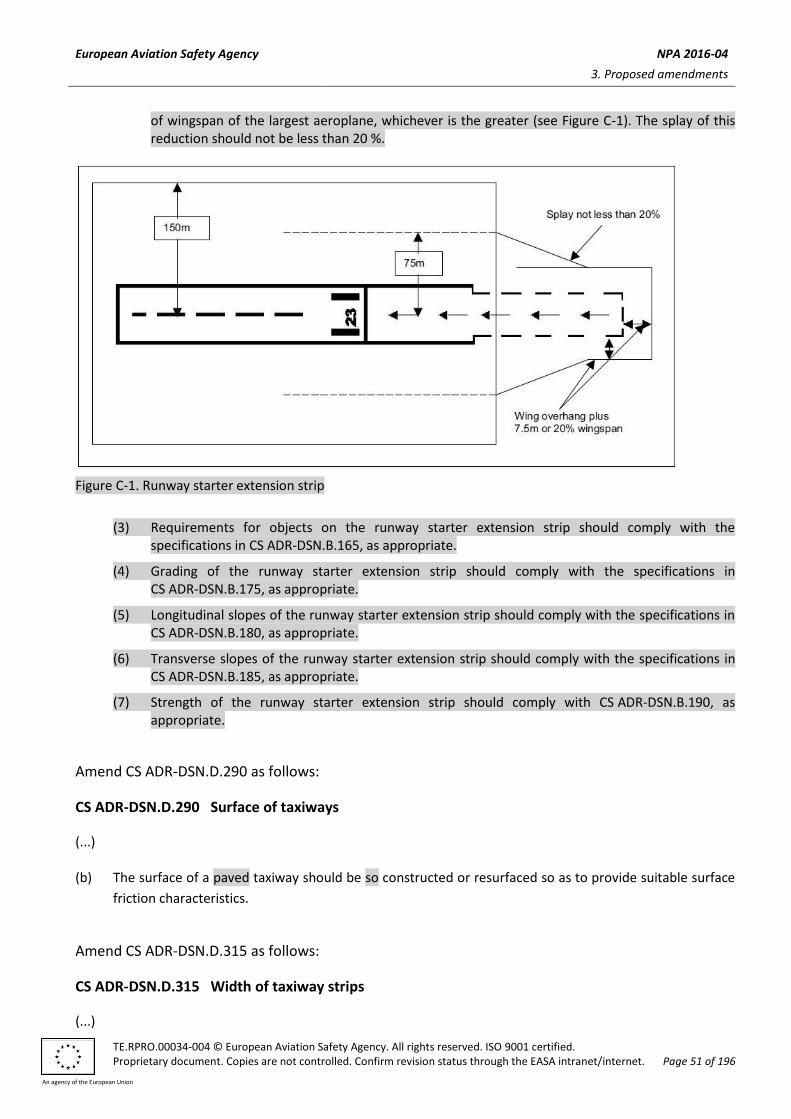
European Aviation Safety Agency NPA 2016-04
3. Proposed amendments
TE.RPRO.00034-004 © European Aviation Safety Agency. All rights reserved. ISO 9001 certified. Proprietary document. Copies are not controlled. Confirm revision status through the EASA intranet/internet. Page 51 of 196
An agency of the European Union
of wingspan of the largest aeroplane, whichever is the greater (see Figure C-1). The splay of this reduction should not be less than 20 %.
Figure C-1. Runway starter extension strip
(3) Requirements for objects on the runway starter extension strip should comply with the specifications in CS ADR-DSN.B.165, as appropriate.
(4) Grading of the runway starter extension strip should comply with the specifications in CS ADR-DSN.B.175, as appropriate.
(5) Longitudinal slopes of the runway starter extension strip should comply with the specifications in CS ADR-DSN.B.180, as appropriate.
(6) Transverse slopes of the runway starter extension strip should comply with the specifications in CS ADR-DSN.B.185, as appropriate.
(7) Strength of the runway starter extension strip should comply with CS ADR-DSN.B.190, as appropriate.
Amend CS ADR-DSN.D.290 as follows:
CS ADR-DSN.D.290 Surface of taxiways
(...) (b) The surface of a paved taxiway should be so constructed or resurfaced so as to provide suitable surface
friction characteristics.
Amend CS ADR-DSN.D.315 as follows:
CS ADR-DSN.D.315 Width of taxiway strips
(...)

European Aviation Safety Agency NPA 2016-04
3. Proposed amendments
TE.RPRO.00034-004 © European Aviation Safety Agency. All rights reserved. ISO 9001 certified. Proprietary document. Copies are not controlled. Confirm revision status through the EASA intranet/internet. Page 52 of 196
An agency of the European Union
(b) A taxiway strip should extend symmetrically on each side of the centre line of the taxiway throughout
the length of the taxiway to at least the distance from the centre line given in Table D-1, column (11).
Amend CS ADR-DSN.D.335 as follows:
CS ADR-DSN.D.335 Holding bays, runway-holding positions, intermediate holding positions, and
road-holding positions
(...)
(b) A runway-holding position or positions should be established:
(1) on the taxiway, if the location or alignment of the taxiway is such that a taxiing/holding aircraft or
vehicle can infringe an obstacle limitation surface or ILS/MLS critical/sensitive area or interfere
with the operation of radio navigation aids;
(2) on the taxiway, at the intersection of a taxiway and a runway; and
(3) at an intersection of a runway with another runway when the former runway is part of a standard
taxi-route.
(...)
Amend CS ADR-DSN.D.340 as follows:
CS ADR-DSN.D.340 Location of holding bays, runway-holding positions, intermediate holding
positions, and road-holding positions
(...)
(c) The location of a runway-holding position es350tablished in accordance with CS ADR-DSN.D.335 should be such that a holding aircraft or vehicle will not infringe the obstacle limitation surfaces or ILS/MLS critical/ sensitive area or interfere with the operation of radio navigation aids.
Code numberd
Type of runway 1 2 3 4
Non-instrument 30 m 40 m 75 m 75 m
Non-precision approach 40 m 40 m 75 m 75 m
Precision approach cCategory I 60 mb 60 mb 90 ma,b 90 ma,b,c
Precision approach categories II and III — — 90 ma,b 90 ma,b,c
Take-off runway 30 m 40 m 75 m 75 m
a. If a holding bay, runway-holding position, or road-holding position is at a lower elevation compared to

European Aviation Safety Agency NPA 2016-04
3. Proposed amendments
TE.RPRO.00034-004 © European Aviation Safety Agency. All rights reserved. ISO 9001 certified. Proprietary document. Copies are not controlled. Confirm revision status through the EASA intranet/internet. Page 53 of 196
An agency of the European Union
the threshold, the distance may be decreased 5 m for every metre the bay or holding position is lower
than the threshold, contingent upon not infringing the inner transitional surface.
b. This distance may need to be increased to avoid interference with radio navigation aids, particularly the
glide path and localiser facilities (see CS ADR-DSN.D.340).
Note 1:.— The distance of 90 m for code number 3 or 4 is based on an aircraft with a tail height of 20 m, a distance from the nose to the highest part of the tail of 52.7 m and a nose height of 10 m holding at an angle of 45° or more with respect to the runway centre line, being clear of the obstacle free zone and not accountable for the calculation of OCA/H.
Note 2:.— The distance of 60 m for code number 2 is based on an aircraft with a tail height of 8 m, a distance from the nose to the highest part of the tail of 24.6 m and a nose height of 5.2 m holding at an angle of 45° or more with respect to the runway centre line, being clear of the obstacle free zone.
c. Where the code letter is F, this distance should be 107.5 m.
Note:.— The distance of 107.5 m for code number 4 where the code letter is F is based on an aircraft with a tail height of 24 m, a distance from the nose to the highest part of the tail of 62.2 m and a nose height of 10 m holding at an angle of 45° or more with respect to the runway centre line, being clear of the obstacle free zone.
d. Elevation of taxiway should be taken into account for possible increase of the distances indicated in this
table.
Table D-2. — Minimum distance from the runway centre line to a holding bay, runway-holding position, or road-holding position
Amend CS ADR-DSN.D.350 as follows:
CS ADR-DSN.E.350 Size of aprons
iIntentionally left blank
Amend CS ADR-DSN.E.360 as follows:
CS ADR-DSN.E.360 Slopes on aprons
(a) Slopes on an apron, including those on an aircraft stand taxilane, should be sufficient to prevent
accumulation of water on the surface of the apron but should be kept to the minimum required to
facilitate effective drainage.
(...)
Amend CS ADR-DSN.E.365 as follows:
CS ADR-DSN.E.365 Clearance distances on aircraft stands
(...)
(b) An aircraft stand should provide the following minimum clearances between an aircraft entering or
exiting using the stand and any adjacent building, aircraft on another stand and other objects:

European Aviation Safety Agency NPA 2016-04
3. Proposed amendments
TE.RPRO.00034-004 © European Aviation Safety Agency. All rights reserved. ISO 9001 certified. Proprietary document. Copies are not controlled. Confirm revision status through the EASA intranet/internet. Page 54 of 196
An agency of the European Union
Code Letter Clearance
A 3 m
B 3 m
C 4.5 m
D 7.5 m
E 7.5 m
F 7.5 m
Amend CS ADR-DSN.H.410 as follows:
CS ADR-DSN.H.410 Outer horizontal surface
iIntentionally left blank
Amend CS ADR-DSN.H.420 as follows:
CS ADR-DSN.H.420 Inner horizontal surface
(...)
(c) Characteristics: The outer limits of the inner horizontal surface are defined by a circle circular arcs
centred on the geometric centre of the runway, by a circular arcs centred on the intersections of the
extended RWY centre line with the end of the RWY strip, joined tangentially by straight lines, as shown
in Figure H-1, or on other points established for such purpose.as in Figure H-1.
Amend CS ADR-DSN.H.440 as follows:
CS ADR-DSN.H.440 Slewed take-off climb surface
iIntentionally left blank
Amend CS ADR-DSN.H.445 as follows:
CS ADR-DSN.H.445 Obstacle Ffree Zzone (OFZ)
(a) An OFZ is intended to protect aeroplanes from fixed and mobile obstacles during Category I, II, or and III
operations when approaches are continued below decision height, and during any subsequent missed
approach or balked landing with all engines operating normally. It is not intended to supplant the
requirement of other surfaces or areas where these are more demanding.
(...)

European Aviation Safety Agency NPA 2016-04
3. Proposed amendments
TE.RPRO.00034-004 © European Aviation Safety Agency. All rights reserved. ISO 9001 certified. Proprietary document. Copies are not controlled. Confirm revision status through the EASA intranet/internet. Page 55 of 196
An agency of the European Union
Amend CS ADR-DSN.J.470 as follows:
CS ADR-DSN.J.470 Non-instrument runways
(...)
(d) New objects or extensions of existing objects should not be permitted above the conical surface or inner
horizontal surface except when the object would be shielded by an existing immovable object, or if after
safety assessment, it is determined that the object would not adversely affect the safety or significantly
affect the regularity of operations of aeroplanes.
(e) Existing objects above any of the conical surface, inner horizontal surface, approach surface and
transitional surfaces should, as far as practicable, be removed except when the object is shielded by an
existing immovable object, or if after safety assessment, it is determined that the object would not
adversely affect the safety or significantly affect the regularity of operations of aeroplanes.
(...)
Amend CS ADR-DSN.J.475 as follows:
CS ADR-DSN.J.475 Non-precision approach runways
(...)
(f) Existing objects above any of the surfaces required by paragraph (a) should as far as practicable be
removed except when the object would be shielded by an existing immovable object, or if after safety
assessment, it is determined that the object would not adversely affect the safety or significantly affect
the regularity of operations of aeroplanes.
Amend CS ADR-DSN.J.480 as follows:
CS ADR-DSN.J.480 Precision approach runways
(a) The following obstacle limitation surfaces should be established for a precision approach runway
cCategory I:
(1) conical surface;
(2) inner horizontal surface;
(3) approach surface; and
(4) transitional surfaces.
(b) The following obstacle limitation surfaces should be established for a precision approach runway
cCategory II or III:

European Aviation Safety Agency NPA 2016-04
3. Proposed amendments
TE.RPRO.00034-004 © European Aviation Safety Agency. All rights reserved. ISO 9001 certified. Proprietary document. Copies are not controlled. Confirm revision status through the EASA intranet/internet. Page 56 of 196
An agency of the European Union
(1) conical surface;
(2) inner horizontal surface;
(3) approach surface and inner approach surface;
(4) transitional surfaces and inner transitional surfaces; and
(5) balked landing surface.
(...)
(g) New objects or extensions of existing objects should not be permitted above the conical surface and the
inner horizontal surface except when an object would be shielded by an existing immovable object, or if
after safety assessment , it is determined that the object would not adversely affect the safety or
significantly affect the regularity of operations of aeroplanes.
(h) Existing objects above an approach surface, a transitional surface, the conical surface and inner
horizontal surface should, as far as practicable, be removed except when an object would be shielded by
an existing immovable object, or if after safety assessment, it is determined that the object would not
adversely affect the safety or significantly affect the regularity of operations of aeroplanes.
Amend CS ADR-DSN.J.485 as follows:
CS ADR-DSN.J.485 Runways meant for take-off (...)
(e) Existing objects that extend above a take-off climb surface should as far as practicable be removed
except when an object is shielded by an existing immovable object, or if after safety assessment, it is
determined that the object would not adversely affect the safety or significantly affect the regularity of
operations of aeroplanes.
RUNWAYS MEANT FOR TAKE-OFF
Code number
Surface and dimensionsa 1 2 3 or 4
(1) (2) (3) (4)
TAKE-OFF CLIMB
Length of inner edge 60e m 80e m 180 m
Distance from runway endb 30 m 60 m 60 m
Divergence (each side) 10 % 10 % 12.5 %
Final width 380 m 580 m 1 200 m 1 800 mc

European Aviation Safety Agency NPA 2016-04
3. Proposed amendments
TE.RPRO.00034-004 © European Aviation Safety Agency. All rights reserved. ISO 9001 certified. Proprietary document. Copies are not controlled. Confirm revision status through the EASA intranet/internet. Page 57 of 196
An agency of the European Union
Length 1 600 m 2 500 m 15 000 m
Slope 5 % 4 % 2 %d
a All dimensions are measured horizontally unless specified otherwise. b The take-off climb surface starts at the end of the clearway if the clearway length exceeds the specified
distance. c 1 800 m when the intended track includes changes of heading greater than 15° for operations conducted
in IMC, VMC by night. d See GM1CS ADR-DSN.J.485 (ac) and (e). e Where clearway is provided the length of the inner edge should be 150 m.
Table J-2. Dimensions and slopes of obstacle limitation surfaces — Runways meant for take-off
Amend CS ADR-DSN.J.490 as follows:
CS ADR-DSN.J.48690 Other objects
(...)
Insert new CS ADR-DSN.J.487 as follows:
CS ADR-DSN.J.487 Objects outside the obstacle limitation surfaces
(a) Applicability: The specifications in paragraph (b) below apply only to the area under control of the
aerodrome operator.
(b) In areas beyond the limits of the obstacle limitation surfaces, at least those objects which extend to a
height of 150 m or more above ground elevation should be regarded as obstacles, unless a safety
assessment indicates that they do not constitute a hazard to aeroplanes.
Amend CS ADR-DSN.K.505 as follows:
CS ADR-DSN.K.505 Signal panels and signal area
iIntentionally left blank
Amend CS ADR-DSN.K.510 as follows:
CS ADR-DSN.K.510 Location of signal panels and signal area
iIntentionally left blank

European Aviation Safety Agency NPA 2016-04
3. Proposed amendments
TE.RPRO.00034-004 © European Aviation Safety Agency. All rights reserved. ISO 9001 certified. Proprietary document. Copies are not controlled. Confirm revision status through the EASA intranet/internet. Page 58 of 196
An agency of the European Union
Amend CS ADR-DSN.K.515 as follows:
CS ADR-DSN.K.515 Characteristics of signal panels and signal area
iIntentionally left blank
Amend CS ADR-DSN.L.530 as follows:
CS ADR-DSN.L.530 Runway centre line marking
(...)
(c) Characteristics:
(...)
(2) The width of the stripes should be not less than:
(i) 0.90 m on precision approach cCategory II and III runways;
(ii) 0.45 m on non-precision approach runways where the code number is 3 or 4, and precision
approach cCategory I runways; and
(iii) 0.30 m on non-precision approach runways where the code number is 1 or 2, and on non-
instrument runways.
Amend CS ADR-DSN.L.535 as follows:
CS ADR-DSN.L.535 Threshold marking
(1) Applicability and location: A threshold marking should be provided at the threshold of a runway.
(...)
Amend CS ADR-DSN.L.545 as follows:
CS ADR-DSN.L.545 Touchdown zone marking
(...)
(c) Characteristics:
(...)
(2) The lateral spacing between the inner sides of the rectangles should be equal to that of the
aiming point marking where provided. Where an aiming point marking is not provided, the lateral
spacing between the inner sides of the rectangles should correspond to the lateral spacing
specified for the aiming point marking in Table L-1 (columns (2), (3), (4), or (5), as appropriate).

European Aviation Safety Agency NPA 2016-04
3. Proposed amendments
TE.RPRO.00034-004 © European Aviation Safety Agency. All rights reserved. ISO 9001 certified. Proprietary document. Copies are not controlled. Confirm revision status through the EASA intranet/internet. Page 59 of 196
An agency of the European Union
The pairs of markings should be provided at longitudinal spacings of 150 m beginning from the
threshold except that where pairs of touchdown zone markings are coincident with or located
within 50 m of an aiming point, marking should be deleted from the pattern.
(...)
Insert new CS ADR-DSN.L.567 as follows:
CS ADR-DSN.L.567 Marking of runway starter extension
(a) Applicability: A marking of the runway starter extension should comply with the specifications in CS ADR-DSN.L.550.
(b) Location: (1) Edge marking of the runway starter extension should be placed along each edge and transverse
side at the start of the runway starter extension, with the outer edge approximately on the edge of the pavement.
(2) Centre line marking of the runway starter extension should be placed along the centre line. When the end of the runway starter extension is not associated with the taxiway and the aeroplane is assumed to backtrack to the start position for take-off, the runway centre line marking of starter extension should indicate the safe turnaround path of the aeroplane.
(c) Characteristics: (1) Edge marking of the runway starter extension should be dashed white line (see Figure L-5A).
(2) Centre line marking of the runway starter extension should be yellow and be at least 15 cm in width.
(3) Where the end of the runway starter extension is not associated with the taxiway, the centre line of the runway starter extension should indicate the path for the aeroplane to make a turnaround.
(4 The runway starter extension should be provided with arrows conforming to Figure L-3(B) showing in the direction of take-off.

European Aviation Safety Agency NPA 2016-04
3. Proposed amendments
TE.RPRO.00034-004 © European Aviation Safety Agency. All rights reserved. ISO 9001 certified. Proprietary document. Copies are not controlled. Confirm revision status through the EASA intranet/internet. Page 60 of 196
An agency of the European Union
Figure L-5A. Marking of the runway starter extension
Amend CS ADR-DSN.L.570 as follows:
CS ADR-DSN.L.570 Enhanced taxiway centre line marking
(a) Applicability: Where provided, Aan enhanced taxiway centre line marking should be installed at each taxiway/runway intersection. extend from the runway holding position Pattern A (as defined in Figure L-5. Taxiway markings) to a distance of up to 47 m (a minimum of three (3) dashed lines) in the direction of travel away from the runway or to the next runway holding position if within 47 m distance.
(b) Characteristics:
(1) Enhanced taxiway centre line marking should be as shown in Figure L-6. An enhanced taxiway
centre line marking should extend from the runway-holding position Pattern A (as defined in
Figure L-5) to a distance of up to 47 m in the direction of travel away from the runway (see Figure
L-6(a)).
(2) If the enhanced taxiway centre line marking intersects another runway-holding position
marking, such as for a precision approach Category II or III runway, that is located within 47 m of
the first runway-holding position marking, the enhanced taxiway centre line marking should be
interrupted 0.9 m prior to and after the intersected runway-holding position marking. The
enhanced taxiway centre line marking should continue beyond the intersected runway-holding

European Aviation Safety Agency NPA 2016-04
3. Proposed amendments
TE.RPRO.00034-004 © European Aviation Safety Agency. All rights reserved. ISO 9001 certified. Proprietary document. Copies are not controlled. Confirm revision status through the EASA intranet/internet. Page 61 of 196
An agency of the European Union
position marking for at least three dashed line segments or 47 m from start to finish,
whichever is greater (see Figure L-6(b)).
(3) If the enhanced taxiway centre line marking continues through a taxiway/taxiway intersection
that is located within 47 m of the runway-holding position marking, the enhanced taxiway centre
line marking should be interrupted 1.5 m prior to and after the point where the intersected
taxiway centre line crosses the enhanced taxiway centre line. The enhanced taxiway centre line
marking should continue beyond the taxiway/taxiway intersection for at least three dashed line
segments or 47 m from start to finish, whichever is greater (see Figure L-6(c)).
[Editorial Note: Remove exiting Figure L-6]

European Aviation Safety Agency NPA 2016-04
3. Proposed amendments
TE.RPRO.00034-004 © European Aviation Safety Agency. All rights reserved. ISO 9001 certified. Proprietary document. Copies are not controlled. Confirm revision status through the EASA intranet/internet. Page 62 of 196
An agency of the European Union
[Editorial Note: Insert new Figure L-6]
Figure L-6. Enhanced taxiway centre line marking
Amend CS ADR-DSN.L.575 as follows:
CS ADR-DSN.L.575 Runway-holding position marking
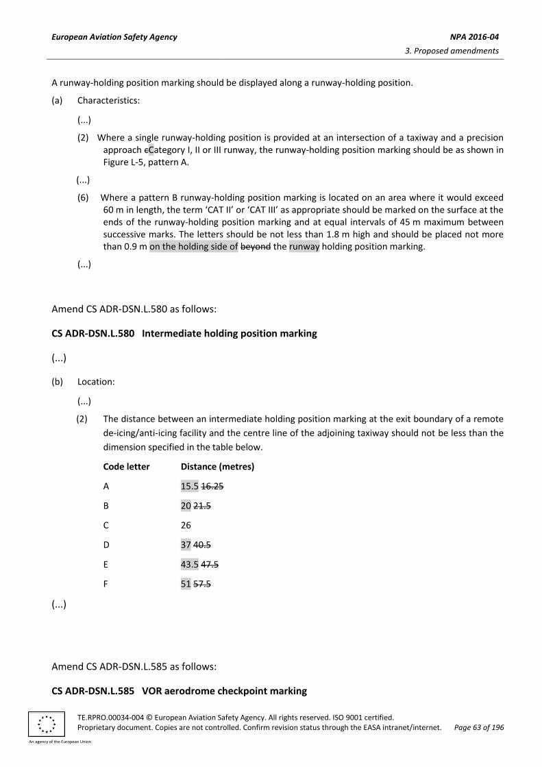
European Aviation Safety Agency NPA 2016-04
3. Proposed amendments
TE.RPRO.00034-004 © European Aviation Safety Agency. All rights reserved. ISO 9001 certified. Proprietary document. Copies are not controlled. Confirm revision status through the EASA intranet/internet. Page 63 of 196
An agency of the European Union
A runway-holding position marking should be displayed along a runway-holding position.
(a) Characteristics:
(...)
(2) Where a single runway-holding position is provided at an intersection of a taxiway and a precision approach cCategory I, II or III runway, the runway-holding position marking should be as shown in Figure L-5, pattern A.
(...)
(6) Where a pattern B runway-holding position marking is located on an area where it would exceed 60 m in length, the term ‘CAT II’ or ‘CAT III’ as appropriate should be marked on the surface at the ends of the runway-holding position marking and at equal intervals of 45 m maximum between successive marks. The letters should be not less than 1.8 m high and should be placed not more than 0.9 m on the holding side of beyond the runway holding position marking.
(...)
Amend CS ADR-DSN.L.580 as follows:
CS ADR-DSN.L.580 Intermediate holding position marking
(...)
(b) Location:
(...)
(2) The distance between an intermediate holding position marking at the exit boundary of a remote
de-icing/anti-icing facility and the centre line of the adjoining taxiway should not be less than the
dimension specified in the table below.
Code letter Distance (metres)
A 15.5 16.25
B 20 21.5
C 26
D 37 40.5
E 43.5 47.5
F 51 57.5
(...)
Amend CS ADR-DSN.L.585 as follows:
CS ADR-DSN.L.585 VOR aerodrome checkpoint marking

European Aviation Safety Agency NPA 2016-04
3. Proposed amendments
TE.RPRO.00034-004 © European Aviation Safety Agency. All rights reserved. ISO 9001 certified. Proprietary document. Copies are not controlled. Confirm revision status through the EASA intranet/internet. Page 64 of 196
An agency of the European Union
(a) Applicability: When a VOR aerodrome check-point is established, it should be indicated by a VOR
aerodrome check-point marking and sign.
(...)
Insert new CS ADR-DSN.L.597 as follows:
CS ADR-DSN.L.597 Apron service road marking
(a) Applicability: The limits of an apron service road, should be defined by service road markings.
(b) Location: Apron service road markings should define the areas intended for use by ground vehicles and other aircraft servicing equipment to provide safe separation from aircraft.
(c) Characteristics:
(1) Apron service road markings should be white.
(2) Apron service road markings should be continuous in length on the edges, continuous or broken in the middle, as appropriate, and at least 10 cm in width.
(3) Apron service road marking should be laterally dashed on edges when apron service road crosses a taxiway or aircraft stand taxilane. Dimensions of the stripes are 1.0 m x 0.1 m.
(d) Apron service road markings should be interrupted when they intersect with other markings on an apron.
Amend CS ADR-DSN.L.600 as follows:
CS ADR-DSN.L.600 Road-holding position marking
(a) Applicability: A road-holding position marking should be provided at all road entrances to a runway or
where a road intersects a taxiway.
(...)
(c) Characteristics:
(1) The road-holding position marking should be in accordance with the local road traffic regulations.
(2) The road-holding position marking at the intersection of a road with a taxiway should be in
accordance with the local road traffic regulations for a yield right-of-way.
Amend CS ADR-DSN.L.605 as follows:
CS ADR-DSN.L.605 Mandatory instruction marking
(...)

European Aviation Safety Agency NPA 2016-04
3. Proposed amendments
TE.RPRO.00034-004 © European Aviation Safety Agency. All rights reserved. ISO 9001 certified. Proprietary document. Copies are not controlled. Confirm revision status through the EASA intranet/internet. Page 65 of 196
An agency of the European Union
Figure L-9. Mandatory instruction marking

European Aviation Safety Agency NPA 2016-04
3. Proposed amendments
TE.RPRO.00034-004 © European Aviation Safety Agency. All rights reserved. ISO 9001 certified. Proprietary document. Copies are not controlled. Confirm revision status through the EASA intranet/internet. Page 66 of 196
An agency of the European Union
Amend CS ADR-DSN.L.610 as follows:
CS ADR-DSN.L.610 Information marking
(...)
Figure L-9. Mandatory instruction marking
Amend CS ADR-DSN.M.615 as follows:
CS ADR-DSN.M.615 General
(...)
(b) Elevated lights:
Elevated runway, stopway, runway starter extension and taxiway lights should be frangible. Their height
should be sufficiently low to preserve clearance for propellers and for the engine pods of jet aircraft.
(c) Surface lights:
(1) Light fixtures inset in the surface of runways, stopways, runway starter extension, taxiways, and
aprons should be so designed and fitted as to withstand being run over by the wheels of an
aircraft without damage either to the aircraft or to the lights themselves.
(...)

European Aviation Safety Agency NPA 2016-04
3. Proposed amendments
TE.RPRO.00034-004 © European Aviation Safety Agency. All rights reserved. ISO 9001 certified. Proprietary document. Copies are not controlled. Confirm revision status through the EASA intranet/internet. Page 67 of 196
An agency of the European Union
(d) Light intensity and control:
(1) The intensity of runway lighting and runway starter extension lighting should be adequate for the
minimum conditions of visibility and ambient light in which use of the runway is intended, and
compatible with that of the nearest section of the approach lighting system when provided.
(2) Where a high-intensity lighting system is provided, a suitable intensity control should be
incorporated to allow for adjustment of the light intensity to meet the prevailing conditions.
Separate intensity controls or other suitable methods should be provided to ensure that the
following systems when installed, can be operated at compatible intensities:
(i) approach lighting system;
(ii) runway edge lights;
(iii) runway threshold lights;
(iv) runway end lights;
(v) runway centre line lights;
(vi) runway touchdown zone lights; and
(vii) taxiway centre line lights; and
(viii) runway starter extension lighting.
(...)
Delete SECTION 1 as follows:
SECTION 1 – APPROACH LIGHTING SYSTEM
Amend CS ADR-DSN.M.625 as follows:
CS ADR-DSN.M.625 Approach lighting systems, general and applicability
(a) The safety objective of the approach lighting system is to provide visual guidance for alignment and roll
guidance, and limited distance-to-go information to enable safe approach to a runway.
(b) Non-instrument runway
Applicability: Where physically practicable, a simple approach lighting system as specified in CS ADR-DSN.M.626 should be provided to serve a non-instrument runway where the code number is 3 or 4, and intended for use at night, except when the runway is used only in conditions of good visibility, and sufficient guidance is provided by other visual aids.
(c) Non-precision approach runway
Applicability: Where physically practicable, a simple approach lighting system specified in CS ADR-DSN.M.626 should be provided to serve a non-precision approach runway, except when the runway is used only in conditions of good visibility or sufficient guidance is provided by other visual aids.

European Aviation Safety Agency NPA 2016-04
3. Proposed amendments
TE.RPRO.00034-004 © European Aviation Safety Agency. All rights reserved. ISO 9001 certified. Proprietary document. Copies are not controlled. Confirm revision status through the EASA intranet/internet. Page 68 of 196
An agency of the European Union
(d) Precision approach runway cCategory I
Applicability: Where physically practicable, a precision approach cCategory I lighting system as specified in CS ADR-DSN.M.630 should be provided to serve a precision approach runway cCategory I.
(e) Precision approach runway categories II and III
Applicability: A precision approach cCategory II and III lighting system as specified in CS ADR-DSN.M.635 should be provided to serve a precision approach runway cCategory II or III.
Amend CS ADR-DSN.M.626 as follows:
CS ADR-DSN.M.626 Simple approach lighting systems
(a) Location and composition:
(i) A simple approach lighting system should consist of a row of lights on the extended centre line of
the runway extending whenever possible, over a distance of not less than 420 m from the
threshold with a row of lights forming a crossbar 18 m or 30 m in length at a distance of 300 m
from the threshold (see Figure M-1).
(ii) The certification specifications, as prescribed in Book 1 provide for the basic characteristics for
simple approach lighting systems. For certain aspects of these systems, some latitude is
permitted, for example, in the spacing between centre line lights and crossbars.
(...)
Amend CS ADR-DSN.M.630 as follows:
CS ADR-DSN.M.630 Precision approach cCategory I lighting system
(a) The safety objective of the approach lighting system is to provide visual guidance for alignment and roll
guidance, and limited distance-to-go information to enable safe approach to a runway.
(b) Location and composition
(1) General: A precision approach cCategory I lighting system should consist of a row of lights on the
extended centre line of the runway extending wherever possible, over a distance of 900 m from
the runway threshold with a row of lights forming a crossbar 30 m in length at a distance of 300 m
from the runway threshold (see Figure M-2).
(...)
(c) Characteristics:
(1) The centre line and crossbar lights of a precision approach cCategory I lighting system should be
fixed lights showing variable white. Each centre line light position should consist of either:
(...)
(3) If the centre line consists of lights as described in paragraph M.630(c)(1)(i) or M.630(c)(2)(i)
above, additional crossbars of lights to the crossbar provided at 300 m from the threshold should

European Aviation Safety Agency NPA 2016-04
3. Proposed amendments
TE.RPRO.00034-004 © European Aviation Safety Agency. All rights reserved. ISO 9001 certified. Proprietary document. Copies are not controlled. Confirm revision status through the EASA intranet/internet. Page 69 of 196
An agency of the European Union
be provided at 150 m, 450 m, 600 m and 750 m from the threshold. The lights forming each
crossbar should be as nearly as practicable in a horizontal straight line at right angles to, and
bisected by, the line of the centre line lights. The lights should be spaced so as to produce a linear
effect, except that gaps may be left on each side of the centre line. These gaps should be kept to a
minimum to meet local requirements and each should not exceed 6 m.
(...)
(5) The chromaticity and characteristics of lights should be in accordance with the specifications in CS
ADR-DSN.U.930 and CS ADR-DSN.U.940, Figure U-5. The chromaticity of lights should be in
accordance with the specifications in CS ADR-DSN.U.930 and Figure U-1.
(6) If the centre line consists of barrettes as described in paragraph M.630(c)(1)(ii) or M.630(c)(2)(ii)
above, each barrette should be supplemented by a capacitor discharge light, except where such
lighting is considered unnecessary taking into account the characteristics of the system, and the
nature of the meteorological conditions.
(7) Each capacitor discharge light as described in paragraph M.630(c)(6) should be flashed twice a
second in sequence, beginning with the outermost light and progressing toward the threshold to
the innermost light of the system. The design of the electrical circuit should be such that these
lights can be operated independently of the other lights of the approach lighting system.
Figure M-2. Precision approach cCategory I lighting systems
Amend CS ADR-DSN.M.635 as follows:
CS ADR-DSN.M.635 Precision approach cCategory II and III lighting system
(a) Location and composition:

European Aviation Safety Agency NPA 2016-04
3. Proposed amendments
TE.RPRO.00034-004 © European Aviation Safety Agency. All rights reserved. ISO 9001 certified. Proprietary document. Copies are not controlled. Confirm revision status through the EASA intranet/internet. Page 70 of 196
An agency of the European Union
(...)
(6) If the centre line beyond a distance of 300 m from the threshold consists of lights as described in
paragraphs M.635(b)(2)(ii) and M.635(b)(32)(ii) below, additional crossbars of lights should be
provided at 450 m, 600 m and 750 m from the threshold. Where such additional crossbars are
incorporated in the system, the outer ends of these crossbars should lie on two straight lines that
either are parallel to the centre line or converge to meet the runway centre line 300 m from the
threshold.
(...)
(b) Characteristics:
(1) The centre line of a precision approach cCategory II and III lighting system for the first 300 m from
the threshold should consist of barrettes showing variable white, except that where the threshold
is displaced 300 m or more, the centre line may consist of single light sources showing variable
white. Where the serviceability level of the approach lights specified in CS ADR.DSN.S.895 can be
demonstrated, the centre line of a precision approach cCategory II and III lighting system for the
first 300 m from the threshold may consist of:
(i) barrettes where the centre line beyond 300 m from the threshold consists of barrettes as
described in paragraph M.635(b)(3)(i) below; or
(ii) alternate single light sources and barrettes, where the centre line beyond 300 m from the
threshold consists of single light sources as described in paragraph M.635(b)(3)(ii) below,
with the innermost single light source located 30 m and the innermost barrette located
60 m from the threshold; or
(iii) single light sources where the threshold is displaced 300 m or more;
all of which should show variable white.
(...)
(5) If the centre line beyond 300 m from the threshold consists of barrettes as described in
paragraphs M.635(b)(2)(i) and M.635(b)(3)(i), each barrette beyond 300 m should be
supplemented by a capacitor discharge light, except where such lighting is considered
unnecessary taking into account the characteristics of the system and the nature of the
meteorological conditions.
(...)
(10) The characteristics of lights should be in accordance with the specifications in CS ADR-DSN.U.940,
Figures U-5 and or U-6, as appropriate.
(11) The chromaticity of lights should be in accordance with the specifications in CS ADR-DSN.U.930 and Figure U-1.
Delete SECTION 2 as follows:
SECTION 2– VISUAL APPROACH SLOPE INDICATOR SYSTEM
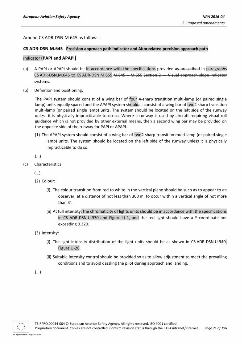
European Aviation Safety Agency NPA 2016-04
3. Proposed amendments
TE.RPRO.00034-004 © European Aviation Safety Agency. All rights reserved. ISO 9001 certified. Proprietary document. Copies are not controlled. Confirm revision status through the EASA intranet/internet. Page 71 of 196
An agency of the European Union
Amend CS ADR-DSN.M.645 as follows:
CS ADR-DSN.M.645 Precision approach path indicator and Abbreviated precision approach path
indicator (PAPI and APAPI)
(a) A PAPI or APAPI should be in accordance with the specifications provided as prescribed in paragraphs
CS ADR-DSN.M.645 to CS ADR-DSN.M.655.M.645 – M.655.Section 2 — Visual approach slope indicator
systems.
(b) Definition and positioning:
The PAPI system should consist of a wing bar of four 4 sharp transition multi-lamp (or paired single lamp) units equally spaced and the APAPI system shouldall consist of a wing bar of two2 sharp transition multi-lamp (or paired single lamp) units. The system should be located on the left side of the runway unless it is physically impracticable to do so. Where a runway is used by aircraft requiring visual roll guidance which is not provided by other external means, then a second wing bar may be provided on the opposite side of the runway for PAPI or APAPI.
(1) The APAPI system should consist of a wing bar of two2 sharp transition multi-lamp (or paired single
lamp) units. The system should be located on the left side of the runway unless it is physically
impracticable to do so.
(...)
(c) Characteristics:
(...)
(2) Colour:
(i) The colour transition from red to white in the vertical plane should be such as to appear to an
observer, at a distance of not less than 300 m, to occur within a vertical angle of not more
than 3´.
(ii) At full intensity, the chromaticity of lights units should be in accordance with the specifications
in CS ADR-DSN.U.930 and Figure U-1, and the red light should have a Y coordinate not
exceeding 0.320.
(3) Intensity:
(i) The light intensity distribution of the light units should be as shown in CS ADR-DSN.U.940,
Figure U-26.
(ii) Suitable intensity control should be provided so as to allow adjustment to meet the prevailing
conditions and to avoid dazzling the pilot during approach and landing.
(...)

European Aviation Safety Agency NPA 2016-04
3. Proposed amendments
TE.RPRO.00034-004 © European Aviation Safety Agency. All rights reserved. ISO 9001 certified. Proprietary document. Copies are not controlled. Confirm revision status through the EASA intranet/internet. Page 72 of 196
An agency of the European Union
[Editorial Note: Insert new Figure M-4]
INSTALLATION TOLERANCES
a) Where a PAPI or APAPI is installed on a runway not equipped with an ILS or MLS, the distance D1 should be calculated to ensure that the lowest height at which a pilot will see a correct approach path indication (Figure M-5, angle B for a PAPI and angle A for an APAPI) provides the wheel clearance over the threshold specified in Table M-1 for the most demanding amongst aeroplanes regularly using the runway.
b) Where a PAPI or APAPI is installed on a runway equipped with an ILS and/or MLS, the distance D1 should be calculated to provide the optimum compatibility between the visual and non-visual aids for the range of eye-to-antenna heights of the aeroplanes regularly using the runway. The distance should be equal to that between the threshold and the effective origin of the ILS glide path or MLS minimum glide path, as appropriate, plus a correction factor for the variation of eye-to-antenna heights of the aeroplanes concerned. The correction factor is obtained by multiplying the average eye-to-antenna height of those aeroplanes by the cotangent of the approach angle. However, the distance should be such that in no case will the wheel clearance over the threshold be lower than that specified in column (3) of Table M-1.
Note: See CS ADR-DSN.L.540 for specifications on aiming point marking. Further guidance on the harmonisation of PAPI, ILS and/or MLS signals is contained in ICAO Doc 9157, Aerodrome Design Manual, Part 4, Visual Aids.
c) If a wheel clearance, greater than that specified in a) above is required for specific aircraft, this can be achieved by increasing D1.
d) Distance D1 should be adjusted to compensate for differences in elevation between the lens centres of the light units and the threshold.
e) To ensure that units are mounted as low as possible and to allow for any transverse slope, small height adjustments of up to 5 cm between units are acceptable. A lateral gradient not greater than 1.25 per cent can be accepted provided it is uniformly applied across the units.
f) A spacing of 6 m (±1 m) between PAPI units should be used on code numbers 1 and 2. In such an event, the inner PAPI unit should be located not less than 10 m (±1 m) from the runway edge.
Note: Reducing the spacing between light units results in a reduction in usable range of the system.
g) The lateral spacing between APAPI units may be increased to 9 m (±1 m) if greater range is required or later conversion to a full PAPI is anticipated. In the latter case, the inner APAPI unit should be located 15 m (±1 m) from the runway edge.
Figure M-4. Siting of PAPI and APAPI
Runway Runway
D1 D1
D
C
B
A
B
A
15 m(±1m)
9 m( 1m)±
9 m( 1m)±
9 m( 1m)±
Thr
esho
ld
Thr
esho
ld
Typical PAPI wing bar Typical APAPI wing bar
10 m( 1m)±
6 m( 1m)±

European Aviation Safety Agency NPA 2016-04
3. Proposed amendments
TE.RPRO.00034-004 © European Aviation Safety Agency. All rights reserved. ISO 9001 certified. Proprietary document. Copies are not controlled. Confirm revision status through the EASA intranet/internet. Page 73 of 196
An agency of the European Union
[Editorial Note: Remove existing Figure M-4]
Figure M-4. Siting of PAPI and APAPI

European Aviation Safety Agency NPA 2016-04
3. Proposed amendments
TE.RPRO.00034-004 © European Aviation Safety Agency. All rights reserved. ISO 9001 certified. Proprietary document. Copies are not controlled. Confirm revision status through the EASA intranet/internet. Page 74 of 196
An agency of the European Union
Amend CS ADR-DSN.M.650 as follows:
CS ADR-DSN.M.650 Approach slope and elevation setting of light units for PAPI and APAPI
(a) Approach slope:
(1) The approach slope as defined in Figure M-5, should be so designed to be appropriate for used by
the aeroplanes in the approach.
(2) When the runway is equipped with an ILS and/or MLS, the siting and the angle of elevation of the
light units should be such that the visual approach slope conforms as closely as possible with the
glide path of the ILS and/or the minimum glide path of the MLS, as appropriate.
(...)

European Aviation Safety Agency NPA 2016-04
3. Proposed amendments
TE.RPRO.00034-004 © European Aviation Safety Agency. All rights reserved. ISO 9001 certified. Proprietary document. Copies are not controlled. Confirm revision status through the EASA intranet/internet. Page 75 of 196
An agency of the European Union
[Editorial Note: Insert new Figure M-5]
Figure M-5. Light beams and angle of elevation setting of PAPI and APAPI
WHITE
WHITE
WHITE
WHITE
RED
RED
RED
RED
3°30
3°10
PAPI approach slope = B + C
2
2°50
2°30
THRESHOLDPAPI WING BAR
The height of the pilot’s eye above the aircraft’s ILS glide path/MLS antenna varies with the type of
aeroplane and approach attitude. Harmonization of the PAPI signal and ILS glide path and/or MLS
minimum glide path to a point closer to the threshold may be achieved by increasing the on-course
sector from 20 to 30 . The setting angles for a 3° glide slope would then be 2°25 , 2°45, 3°15 and
3°35 .
A — 3° PAPI ILLUSTRATED
D
C
B
A
THRESHOLDAPAPI WING BAR
3°15
2°45APAPI approach slope =A + B
2
B — 3° APAPI ILLUSTRATED
B
A
WHITE
WHITE
RED
RED

European Aviation Safety Agency NPA 2016-04
3. Proposed amendments
TE.RPRO.00034-004 © European Aviation Safety Agency. All rights reserved. ISO 9001 certified. Proprietary document. Copies are not controlled. Confirm revision status through the EASA intranet/internet. Page 76 of 196
An agency of the European Union
[Editorial Note: Remove exiting Figure M-5]
Figure M-5. Light beams and angle of elevation setting of PAPI and APAPI

European Aviation Safety Agency NPA 2016-04
3. Proposed amendments
TE.RPRO.00034-004 © European Aviation Safety Agency. All rights reserved. ISO 9001 certified. Proprietary document. Copies are not controlled. Confirm revision status through the EASA intranet/internet. Page 77 of 196
An agency of the European Union
Amend CS ADR-DSN.M.655 as follows:
CS ADR-DSN.M.655 Obstacle protection surface for PAPI and APAPI
(...)
(c) New objects or extensions of existing objects should not be permitted above an obstacle protection
surface except when the new object or extension would be shielded by an existing immovable object, or
if after safety assessment, it is determined that the object would not adversely affect the safety of
operations of aeroplanes.
(...)
Amend CS ADR-DSN.M.660 as follows:
CS ADR-DSN.M.660 Circling guidance lights
(a) Applicability: Circling guidance lights should be provided when existing approach and runway lighting
systems do not satisfactorily permit identification of the runway and/or approach area to a circling
aircraft that are intending to carry out circling approaches.
(...)
Delete SECTION 3 as follows :
SECTION 3 – RUNWAY&TAXIWAY LIGHTS
Amend CS ADR-DSN.M.675 as follows:
CS ADR-DSN.M.675 Runway edge lights
(...)
(d) In all angles of azimuth, as prescribed in paragraph (c)(2) above, runway edge lights should show at
angles up to 15° above the horizontal with intensity adequate for the conditions of visibility and ambient
light in which use of the runway for take-off or landing is intended. In any case, the intensity should be at
least 50 cd except that at an aerodrome without extraneous lighting the intensity of the lights may be
reduced to not less than 25 cd to avoid dazzling the pilot.
(e) Runway edge lights characteristics on a precision approach runway should be in accordance with the
specifications in CS ADR-DSN.U.940, Figure U-13 or Figure U-14, as appropriate.
(f) The chromaticity of lights should be in accordance with the specifications in CS ADR-DSN.U.930 and in Figure U-1.

European Aviation Safety Agency NPA 2016-04
3. Proposed amendments
TE.RPRO.00034-004 © European Aviation Safety Agency. All rights reserved. ISO 9001 certified. Proprietary document. Copies are not controlled. Confirm revision status through the EASA intranet/internet. Page 78 of 196
An agency of the European Union
Amend CS ADR-DSN.M.680 as follows:
CS ADR-DSN.M.680 Runway threshold and wing bar lights
(...)
(b) Location and positioning of runway threshold:
(...)
(3) Threshold lighting should consist of:
(i) on a non-instrument or non-precision approach runway, at least six lights;
(ii) on a precision approach runway cCategory I, at least the number of lights that would be
required if the lights were uniformly spaced at intervals of 3 m between the rows of runway
edge lights; and
(iii) on a precision approach runway cCategory II or III, lights uniformly spaced between the rows
of runway edge lights at intervals of not more than 3 m.
(4) The lights prescribed in paragraphs (b)(3)(i) and (b)(3)(ii) above should be either:
(i) equally spaced between the rows of runway edge lights, or
(ii) symmetrically disposed about the runway centre line in two groups, with the lights uniformly
spaced in each group and with a gap between the groups equal to the gauge of the touchdown
zone marking or lighting, where such is provided, or otherwise not more than half the distance
between the rows of runway edge lights.
(...)
(e) Characteristics of runway threshold and wing bar lights:
(1) Runway threshold and wing bar lights should be fixed unidirectional lights showing green in the
direction of approach to the runway. The intensity and beam spread of the lights should be
adequate for the conditions of visibility and ambient light in which use of the runway is intended.
(2) Runway threshold lights on a precision approach runway should be in accordance with the
specifications in CS ADR-DSN.U.940, Figure U-7.
(3) Threshold wing bar lights on a precision approach runway should be in accordance with the specifications in CS ADR-DSN.U.940, Figure U-8.
(4) The chromaticity of lights should be in accordance with the specifications in CS ADR-DSN.U.930 and Figure U-1.
Amend CS ADR-DSN.M.685 as follows:
CS ADR-DSN.M.685 Runway end lights
(...)
(b) Location and positioning:
(...)

European Aviation Safety Agency NPA 2016-04
3. Proposed amendments
TE.RPRO.00034-004 © European Aviation Safety Agency. All rights reserved. ISO 9001 certified. Proprietary document. Copies are not controlled. Confirm revision status through the EASA intranet/internet. Page 79 of 196
An agency of the European Union
(3) For a precision approach runway cCategory III, the spacing between runway end lights, except
between the two innermost lights if a gap is used, should not exceed 6 m.
(c) Characteristics of runway end lights:
(1) Runway end lights should be fixed unidirectional lights showing red in the direction of the runway. The intensity and beam spread of the lights should be adequate for the conditions of visibility and ambient light in which use of the runway is intended.
(2) Runway end lights characteristics on a precision approach runway should be in accordance with the chromaticity and characteristics specifications in CS ADR-DSN.U.930 and CS ADR-DSN.U.940, Figure U-12.
(3) Runway end lights on a precision approach runway should be in accordance with the chromaticity specifications in CS ADR-DSN.U.930 and Figure U-1.
Amend CS ADR-DSN.M.690 as follows:
CS ADR-DSN.M.690 Runway centre line lights
(...)
(b) Applicability:
(1) Runway centre line lights should be provided on a precision approach runway cCategory II or III.
(2) Runway centre line lights should be provided on a runway intended to be used for take-off with
an operating minimum below an RVR of the order of 400 m.
(...)
(d) Characteristics:
(1) Runway centre line lights should be fixed lights showing variable white from the threshold to the
point 900 m from the runway end; alternate red and variable white from 900 m to 300 m from
the runway end; and red from 300 m to the runway end, except that for runways less than
1 800 m in length, the alternate red and variable white lights should extend from the midpoint of
the runway usable for landing to 300 m from the runway end.
(2) Runway centre line lights characteristics should be in accordance with the specifications inCS
ADR-DSN.U.930 and CS ADR-DSN.U.940, Figure U-10 or Figure U-11, as appropriate.
(3) Runway centre line lights chromaticity should be in accordance with the specifications in CS ADR-DSN.U.930 and Figure U-1.
(e) Centre line guidance for take-off from the beginning of a runway to a displaced threshold should be
provided by:
(1) an approach lighting system if its characteristics and intensity settings afford the guidance
required during take-off, and it does not dazzle the pilot of an aircraft taking off; or
(2) runway centre line lights; or

European Aviation Safety Agency NPA 2016-04
3. Proposed amendments
TE.RPRO.00034-004 © European Aviation Safety Agency. All rights reserved. ISO 9001 certified. Proprietary document. Copies are not controlled. Confirm revision status through the EASA intranet/internet. Page 80 of 196
An agency of the European Union
(3) barrettes of at least 3 m length, and spaced at uniform intervals of 30 m, as shown in Figure M-8,
designed so that their photometric characteristics and intensity setting afford the guidance
required during take-off without dazzling the pilot of an aircraft taking off.
Where necessary, provision should be made to extinguish those centre line lights, as prescribed in paragraph (2) above or reset the intensity of the approach lighting system or barrettes when the runway is being used for landing. In no case should only the single source runway centre line lights show from the beginning of the runway to a displaced threshold when the runway is being used for landing.
Amend CS ADR-DSN.M.695 as follows:
CS ADR-DSN.M.695 Runway touchdown zone lights
(a) Applicability: Touchdown zone lights should be provided in the touchdown zone of a precision approach
runway cCategory II or III.
(...)
(c) Characteristics:
(1) A barrette should be composed of at least three lights with spacing between the lights of not
more than 1.5 m.
(2) A barrette should be not less than 3 m or more than 4.5 m in length.
(3) Touchdown zone lights should be fixed unidirectional lights showing variable white.
(4) Touchdown zone lights characteristics should be in accordance with the chromaticity and
characteristics specifications in in CS ADR-DSN.U.930 and CS ADR-DSN.U.940, Figure U-9.
(5) Touchdown zone lights chromaticity should be in accordance with the specifications in CS ADR-DSN.U.930 and Figure U-1.
Insert new CS ADR-DSN.M.696 as follows:
CS ADR-DSN.M.696 Simple touchdown zone lights
(a) The safety objective of simple touchdown zone lights is to provide pilots with enhanced situational
awareness in all visibility conditions and to help enable pilots to decide whether to commence a go
around if the aircraft has not landed by a certain point on the runway.
(b) Applicability: Except where touchdown zone lights are provided in accordance with CS ADR-DSN.M.695,
at a runway where the approach angle is greater than 3.5 degrees and/or the Landing Distance Available
combined with other factors increases the risk of an overrun, simple touchdown zone lights should be
provided.
(c) Location and positioning:
(1) Simple touchdown zone lights should be a pair of lights located on each side of the runway centre
line 0.3 metres beyond the upwind edge of the final touchdown zone marking.

European Aviation Safety Agency NPA 2016-04
3. Proposed amendments
TE.RPRO.00034-004 © European Aviation Safety Agency. All rights reserved. ISO 9001 certified. Proprietary document. Copies are not controlled. Confirm revision status through the EASA intranet/internet. Page 81 of 196
An agency of the European Union
(2) The lateral spacing between the inner lights of the two pairs of lights should be equal to the
lateral spacing selected for the touchdown zone marking.
(3) The spacing between the lights of the same pair should not be more than 1.5 m or half the width
of the touchdown zone marking, whichever is greater (see Figure M-8(C)).
(4) Where provided on a runway without touchdown zone markings, simple touchdown zone lights
should be installed in such a position that provides the equivalent touchdown zone information.
(d) Characteristics:
(1) Simple touchdown zone lights should be fixed unidirectional lights showing variable white and
aligned so as to be visible to the pilot of a landing aeroplane in the direction of approach to the
runway.
(2) Simple touchdown zone lights characteristics should be in accordance with the specifications in
CS ADR-DSN.U.940, Figure U-9.
(3) Simple touchdown zone lights chromaticity should be in accordance with the specifications in CS
ADR-DSN.U.930 and Figure U-1.
Figure M-8(C). Simple touchdown zone lighting
Amend CS ADR-DSN.M.700 as follows:
CS ADR-DSN.M.700 Rapid exit taxiway indicator lights
intentionally left blank

European Aviation Safety Agency NPA 2016-04
3. Proposed amendments
TE.RPRO.00034-004 © European Aviation Safety Agency. All rights reserved. ISO 9001 certified. Proprietary document. Copies are not controlled. Confirm revision status through the EASA intranet/internet. Page 82 of 196
An agency of the European Union
Amend CS ADR-DSN.M.705 as follows:
CS ADR-DSN.M.705 Stopway lights
(a) Applicability and purpose: Stopway lights should be provided for a stopway intended for use at night.
(b) Location:
(1) Stopway lights should be placed along the full length of the stopway and should be in two parallel rows that are equidistant from the centre line and coincident with the rows of the runway edge
lights. The spacing between the lights should be in accordance with CS ADR-DSN.M.675((b)(4). Stopway lights placed along the edge of the stopway should consist of at least one pair of lights.
(2) At least four uni-directional stopway lights equally spaced across the width of the Sstopway should also be provided across the end of a stopway on a line at right angles to the stopway axis as near to the end of the stopway as possible and, in any case, not more than 3 m outside the end.
(c) Characteristics:
(1) Stopway lights should be fixed unidirectional lights showing red in the direction of the runway.
(2) Stopway lights chromaticity should be in accordance with the specifications in CS ADR-DSN.U.9340
and Figure U-1.
Amend CS ADR-DSN.M.710 as follows:
CS ADR-DSN.M.710 Taxiway centre line lights
(...)
(b) Applicability:
(1) Taxiway centre line lights should be provided on an exit taxiway, taxiway, de-icing/anti-icing
facility, and apron intended for use in runway visual range conditions less than a value of 350 m in
such a manner as to provide continuous guidance between the runway centre line and aircraft
stands, except that these lights need not be provided where the traffic density is light and taxiway
edge lights, and centre line marking provide adequate guidance.
(2) Taxiway centre line lights should be provided on a taxiway intended for use at night in runway
visual range conditions of 350 m or greater, and particularly on complex taxiway intersections and
exit taxiways, except that these lights need not be provided where the traffic density is light and
taxiway edge lights, and centre line marking provide adequate guidance.
(3) Taxiway centre line lights should be provided on an exit taxiway, taxiway, de-icing/anti icing
facility, and apron in all visibility conditions where specified as components of an advanced
surface movement guidance and control system in such a manner as to provide continuous
guidance between the runway centre line and aircraft stands.
(4) Taxiway centre line lights should be provided on a runway forming part of a standard taxi-route
and intended for taxiing in runway visual range conditions less than a value of 350 m, except that

European Aviation Safety Agency NPA 2016-04
3. Proposed amendments
TE.RPRO.00034-004 © European Aviation Safety Agency. All rights reserved. ISO 9001 certified. Proprietary document. Copies are not controlled. Confirm revision status through the EASA intranet/internet. Page 83 of 196
An agency of the European Union
these lights need not be provided where the traffic density is light and taxiway edge lights, and
centre line marking provide adequate guidance.
(...)
(c) Characteristics:
(1) Except as provided for in paragraph (c)(3) below, Ttaxiway centre line lights on a taxiway other
than an exit taxiway and on a runway forming part of a standard taxi-route should be fixed lights
showing green with beam dimensions such that the light is visible only from aeroplanes on, or in
the vicinity of the taxiway.
(2) Taxiway centre line lights on an exit taxiway should be fixed lights. Alternate taxiway centre line
lights should show green and yellow from their beginning near the runway centre line to the
perimeter of the ILS/MLS critical/sensitive area, or the lower edge of the inner transitional
surface, whichever is farthest from the runway; and thereafter all lights should show green, as
shown in Figure M-10. The first light in the exit centre line should always show green and Tthe
light nearest to the perimeter should always show yellow.
Where aircraft follow the same centre line in both directions, the centre line lights should show
green to aircraft approaching the runway.
(3) Where necessary to denote the proximity to a runway, taxiway centre line lights should be fixed
lights showing alternating green and yellow from the perimeter of the ILS/MLS critical/sensitive
area or the lower edge of the inner transitional surface, whichever is farthest from the runway, to
the runway and continue alternating green and yellow until:
(i) their end point near the runway centre line; or
(ii) in the case of the taxiway centre line lights crossing the runway, to the opposite perimeter
of the ILS/MLS critical/sensitive area or the lower edge of the inner transitional surface,
whichever is farthest from the runway.
(4) Taxiway centre line lights should be in accordance with the specifications in CS ADR-DSN.U.940,
Figure U-16, U-17, or U-18, as appropriate, for taxiways intended for use in runway visual range
conditions of less than a value of 350 m; Figure U-19 or Figure U-20, as appropriate, for other
taxiways.
(5) Where higher intensities are required, from an operational point of view, taxiway centre line
lights on rapid exit taxiways intended for use in runway visual range conditions less than a value
of 350 m should be in accordance with the specifications in CS ADR-DSN.U.940, Figure U-16. The
number of levels of brilliancy settings for these lights should be the same as that for the runway
centre line lights.
(6) Where taxiway centre line lights are specified as components of an advanced surface movement
guidance and control system and where, from an operational point of view, higher intensities are
required to maintain ground movements at a certain speed in very low visibilities or in bright
daytime conditions, taxiway centre line lights should be in accordance with the specifications in
CS ADR-DSN.U.940, Figure U-21, U-22, or U-23, as appropriate.
(7) High intensity centre line lights should only be used in case of an absolute necessity and following
a specific study.

European Aviation Safety Agency NPA 2016-04
3. Proposed amendments
TE.RPRO.00034-004 © European Aviation Safety Agency. All rights reserved. ISO 9001 certified. Proprietary document. Copies are not controlled. Confirm revision status through the EASA intranet/internet. Page 84 of 196
An agency of the European Union
(8) Taxiway centre line lights chromaticity should be in accordance with the specifications in CS ADR-DSN.U.930 and Figure U1.
(...)
Amend CS ADR-DSN.M.715 as follows:
CS ADR-DSN.M.715 Taxiway centre line lights on taxiways, runways, rapid exit taxiways, or on
other exit taxiways
(...)
(b) Taxiway centre line lights on taxiways:
(...)
(3) On a taxiway curve the spacing of taxiway centre line lights should be as specified in the Table M-3. intended for use in RVR conditions of less than a value of 350 m, the lights on a curve should not exceed spacing of 15 m, and on a curve of less than 400 m radius the lights should be spaced at intervals of not greater than 7.5 m. This spacing should extend for 60 m before and after the curve.
RVR Radius of taxiway curve Taxiway centre line lights spacing on taxiway curves
< 350 m < 400 m Max. 7.5 m, including 60 m before and after the curve
400 m Max. 15 m
350 m
< 400 m Max. 7.5 m
401 m to 899 m Max. 15 m
> 900 m Max. 30 m
Table M-3. Taxiway centre line lights spacing on taxiway curves
(c) Taxiway centre line lights on other exit taxiways:
(1) Taxiway centre line lights on exit taxiways other than rapid exit taxiways should commence at the
point where the taxiway centre line marking begins to curve from the runway centre line, and
follow the curved taxiway centre line marking at least to the point where the marking leaves the
runway. The first light should be at least 60 cm from any row of runway centre line lights, as
shown in Figure M-9.Arrangement of runway threshold and runway end lights.
(2) The lights should be spaced at longitudinal intervals of not more than 7.5 m.
(...)
(f) Positioning of taxiway centre line lights on taxiway:

European Aviation Safety Agency NPA 2016-04
3. Proposed amendments
TE.RPRO.00034-004 © European Aviation Safety Agency. All rights reserved. ISO 9001 certified. Proprietary document. Copies are not controlled. Confirm revision status through the EASA intranet/internet. Page 85 of 196
An agency of the European Union
(i) The spacing on a particular section of taxiway centre line lighting (straight or curved section) should be such that a clear indication of the taxiway centre line is provided, particularly on a curved section.
(ii) Where a taxiway is only intended for use in RVR conditions of 350 m or greater, the spacing of taxiway centre line lights on curves should not exceed the table below:
Curve radius Light spacing
up to 400 m 7.5 m
401 m to 899 m 15 m
900 m or greater 30 m
(...)
Amend CS ADR-DSN.M.720 as follows:
CS ADR-DSN.M.720 Taxiway edge lights
(...)
(c) Characteristics:
(...)
(4) Taxiway edge lights chromaticity should be in accordance with the specifications in CS ADR-DSN.U.930 and Figure U-1.
Amend CS ADR-DSN.M.725 as follows:
CS ADR-DSN.M.725 Runway turn pad lights
(a) The safety objective of runway turn pad lights is to provide additional guidance on a runway turn pad
intended for use in reduced visibility conditions and at night to enable an aeroplane to complete a safe
180-degree turn, and align with the runway centre line.
(b) Applicability:
(1) Runway turn pad lights should be provided for continuous guidance on a runway turn pad intended for use in runway visual range conditions less than a value of 350 m to enable an aeroplane to complete a 180-degree turn, and align with the runway centre line.
(2) Runway turn pad lights should be provided on a runway turn pad intended for use at night, except that these lights need not be provided where taxiway edge lights and runway turn pad marking provide adequate guidance.
(...)
(d) Characteristics:
(1) Runway turn pad lights should be unidirectional fixed lights showing green with beam dimensions
such that the light is visible only from aeroplanes on or approaching the runway turn pad.

European Aviation Safety Agency NPA 2016-04
3. Proposed amendments
TE.RPRO.00034-004 © European Aviation Safety Agency. All rights reserved. ISO 9001 certified. Proprietary document. Copies are not controlled. Confirm revision status through the EASA intranet/internet. Page 86 of 196
An agency of the European Union
(2) Runway turn pad lights should be in accordance with the specifications in CS ADR-DSN.U.940,
Figure U-17 and or Figure U-18, as appropriate.
(3) Runway turn pad lights chromaticity should be in accordance with the specifications in
CS ADR-DSN.U.930 and Figure U-1.
Insert new CS ADR-DSN.M.727 as follows:
CS ADR-DSN.M.727 Lights of the runway starter extension
(a) Applicability:
(1) Edge lights of the runway starter extension should be provided in accordance with the specifications in CS ADR-DSN.M.675(a), as appropriate;
(2) Centre line lights of the runway starter extension should be provided in accordance with the specifications in CS ADR-DSN.M.690(b), as appropriate.
(b) Location:
(1) Edge lights of the runway starter extension should be placed along the full length of the runway starter extension and should be in two parallel rows that are equidistant from the centre line and coincident with the rows of the runway edge lights or with the edge of the pavement of the runway starter extension. Edge lights of the runway starter extension should be spaced at uniform longitudinal intervals of not more than 60 m. When the beginning of the runway starter extension is not associated with the taxiway at least five edge lights of the runway starter extension should be placed across the transverse side.
(2) Centre line lights of the runway starter extension should be spaced at uniform longitudinal intervals corresponding to the ones of the runway centre line lights, but in any case not more than 30 m.
(3) When the end of the runway starter extension is not associated with the taxiway and the aeroplane is assumed to backtrack to the start position for take-off, the lights should indicate the safe turnaround path of the aeroplane.
(c) Characteristics:
(1) Edge lights of the runway starter extension should be fixed lights showing red in the direction of take-off and blue in the opposite direction (see Figure M-10A).
(2) Red edge lights of the runway starter extension characteristics should be in accordance with the specifications in CS ADR-DSN.M.675, as appropriate, and blue edge lights of the runway starter extension characteristics should be in accordance with the specifications in CS ADR-DSN.M.720, as appropriate.
(3) Red and blue edge lights of the runway starter extension chromaticity should be in accordance with the specifications in CS ADR-DSN.U.930 and Figure U-1, as appropriate.
(4) When the runway starter extension is not associated with the taxiway the centre line lights of the runway starter extension should be fixed uni-directional lights showing white in the direction of take-off (see Figure M-10A(A)).
(5) When the runway starter extension is associated with the taxiway, the centre line lights of the runway starter extension should be fixed lights showing white in the direction of take-off. In the opposite direction of take-off uni-directional taxiway centre line lights should be provided showing alternately green and yellow (first and last light of the runway starter extension should show green), (see Figure M-10A(B)).

European Aviation Safety Agency NPA 2016-04
3. Proposed amendments
TE.RPRO.00034-004 © European Aviation Safety Agency. All rights reserved. ISO 9001 certified. Proprietary document. Copies are not controlled. Confirm revision status through the EASA intranet/internet. Page 87 of 196
An agency of the European Union
(6) White centre line lights of the runway starter extension characteristics should be in accordance with the specifications in CS ADR-DSN.M.690, as appropriate. Green and yellow lights on the runway starter extension centre line should be in accordance with the specifications in CS ADR-DSN.M.715, as appropriate.
(7) White centre line lights of the runway starter extension chromaticity should be in accordance with the specifications in CS ADR-DSN.U.930 and Figure U-1. Green and yellow centre line lights of the runway starter extension chromaticity should be in accordance with the specifications in CS ADR-DSN.U.930 and Figure U-1.
Figure M-10A. Runway starter extension lighting when the aircraft is assumed to backtrack (A) and when associated taxiway is used (B)
Amend CS ADR-DSN.M.730 as follows:
CS ADR-DSN.M.730 Stop bars lights
(a) Applicability:
(1) A stop bar should be provided at every runway-holding position serving a runway when it is
intended that the runway should be used in runway visual range conditions less than a value of
550 m, except where:
(i) appropriate aids and procedures are available to assist in preventing inadvertent incursions
of aircraft and vehicles traffic onto the runway; or
(ii) operational procedures exist to limit, in runway visual range conditions less than a value of
550 m, the number of:
A B

European Aviation Safety Agency NPA 2016-04
3. Proposed amendments
TE.RPRO.00034-004 © European Aviation Safety Agency. All rights reserved. ISO 9001 certified. Proprietary document. Copies are not controlled. Confirm revision status through the EASA intranet/internet. Page 88 of 196
An agency of the European Union
(A) aircraft on the manoeuvring area to one at a time; and
(B) vehicles on the manoeuvring area to the essential minimum.
(2) Where there is more than one stop bar associated with a taxiway/runway intersection, only one should be illuminated at any given time.
(3)(2) A stop bar should be provided at an intermediate holding position when it is desired to supplement markings with lights, and to provide traffic control by visual means.
(...)
(c) Characteristics:
(1) Stop bars should consist of lights spaced at uniform intervals of not more than 3 m across the
taxiway, showing red in the intended direction(s) of approach to the intersection or runway-
holding position.
(2) Stop bars installed at a runway-holding position should be unidirectional, and should show red in
the direction of approach to the runway.
(3) Selectively switchable stop bars should be installed in conjunction with at least three taxiway
centre line lights (extending for a distance of at least 90 m from the stop bar) in the direction that
it is intended for an aircraft to proceed from the stop bar.
(3) The intensity in red light and beam spreads of stop bar lights should be in accordance with the specifications in CS ADR-DSN.U.940, Figures U-16 to U-20, as appropriate.
(4) Where stop bars are specified as components of an advanced surface movement guidance and control system, and where, from an operational point of view, higher intensities are required to maintain ground movements at a certain speed in very low visibilities or in bright daytime conditions, the intensity in red light and beam spreads of stop bar lights should be in accordance with the specifications in CS ADR-DSN.U.940, Figures U-21, U-22 or U-23, as appropriate.
(6) High-intensity stop bars should only be used in case of an absolute necessity and following a specific study.
(5) Where a wide beam fixture is required, the intensity in red light and beam spreads of stop bar lights should be in accordance with the specifications in CS ADR-DSN.U.940, Figure U-21 or Figure U-23, as appropriate.
(6) The lighting circuit should be designed so that:
(i) stop bars located across entrance taxiways are selectively switchable;
(ii) stop bars located across taxiways intended to be used only as exit taxiways are switchable
selectively or in groups;
(iii) when a stop bar is illuminated, any taxiway centre line lights installed beyond the stop bar
should be extinguished for a distance of at least 90 m; and
(iv) stop bars are should be interlocked with the taxiway centre line lights so that when the
centre line lights beyond the stop bar are illuminated, the stop bar is extinguished and vice
versa.
(7) Stop bar lights chromaticity should be in accordance with the specifications in CS ADR-DSN.U.930 and Figure U-1.

European Aviation Safety Agency NPA 2016-04
3. Proposed amendments
TE.RPRO.00034-004 © European Aviation Safety Agency. All rights reserved. ISO 9001 certified. Proprietary document. Copies are not controlled. Confirm revision status through the EASA intranet/internet. Page 89 of 196
An agency of the European Union
Amend CS ADR-DSN.M.735 as follows:
CS ADR-DSN.M.735 Intermediate holding position lights
(...)
(c) Characteristics of intermediate holding position lights:
(1) Intermediate holding position lights should consist of three fixed unidirectional lights showing yellow in the direction of approach to the intermediate holding position with a light distribution similar to taxiway centre line lights if provided.
(2) The lights should be disposed symmetrically about and at right angle to the taxiway centre line, with individual lights spaced 1.5 m apart.
(3) Intermediate holding position lights chromaticity should be in accordance with the specifications in CS ADR-DSN.U.930 and in Figure U1.
Amend CS ADR-DSN.M.740 as follows:
CS ADR-DSN.M.740 De-icing/anti-icing facility exit lights
(...)
(c) Characteristics: Where provided, de-icing/anti-icing facility exit lights should consist of in-pavement fixed
unidirectional lights spaced at intervals of 6 m showing yellow in the direction of the approach to the
exit boundary with a light distribution similar to taxiway centre line lights (see Figure M-11G-1).
(d) De-icing/anti-icing facility exit lights chromaticity should be in accordance with the specifications in CS ADR-DSN.U.930 and Figure U1.
Amend CS ADR-DSN.M.745 as follows:
CS ADR-DSN.M.745 Runway guard lights
(a) The purpose of runway guard lights is to warn pilots and drivers of vehicles when they are operating on
taxiways, that they are about to enter an active runway. There are two standard configurations of
runway guard lights as illustrated in Figure M-12.
(b) Applicability:
(1) Runway guard lights, Configuration A, should be provided at each taxiway/runway intersection
associated with a runway intended for use in:
(i) runway visual range conditions less than a value of 550 m where regardless of whether or
not a stop bar is not installed; and

European Aviation Safety Agency NPA 2016-04
3. Proposed amendments
TE.RPRO.00034-004 © European Aviation Safety Agency. All rights reserved. ISO 9001 certified. Proprietary document. Copies are not controlled. Confirm revision status through the EASA intranet/internet. Page 90 of 196
An agency of the European Union
(ii) runway visual range conditions of values between 550 m and 1 200 m where the traffic
density is heavy.
(2) As part of runway incursion measures, Rrunway guard lights, Configuration A or B, Configuration B,
or both, should be provided at each taxiway/runway intersection where runway incursion hot spots
have been identified, and used under all weather conditions during day and night. enhanced
conspicuity of the taxiway/runway intersection is needed, such as on a wide-throat taxiway, except
that
(3) Configuration B runway guard lights should not be collocated with a stop bar.
(...)
(d) Characteristics:
(...)
(13) Runway guard lights chromaticity should be in accordance with the specifications in CS ADR-DSN.U.930 and Figure U-1.
Delete SECTION 4 as follows :
SECTION 4 — APRON LIGHTING
Amend CS ADR-DSN.M.750 as follows:
CS ADR-DSN.M.750 Apron floodlighting
(a) The purpose of apron floodlighting is to facilitate safe operations on an apron, on a de-icing/anti-icing
facility, and on a designated isolated aircraft parking position intended to be used in reduced visibility
conditions and at night.
(...)
Amend CS ADR-DSN.M.760 as follows:
CS ADR-DSN.M.760 Advanced visual docking guidance system
(a) Application:
(1) Advanced visual docking guidance system (A-VDGS) should be provided where it is operationally
desirable to confirm the correct aircraft type for which guidance is being provided, and/or to
indicate the stand centre line in use, where more than one is provided for.
(...)
(b) Characteristics:
(...)

European Aviation Safety Agency NPA 2016-04
3. Proposed amendments
TE.RPRO.00034-004 © European Aviation Safety Agency. All rights reserved. ISO 9001 certified. Proprietary document. Copies are not controlled. Confirm revision status through the EASA intranet/internet. Page 91 of 196
An agency of the European Union
(4) The information on displacement of the aircraft relative to the stand centre line and distance to
the stopping position, when displayed, should be provided with the accuracy specified in Table M-
43. Symbols and graphics used to depict guidance information should be intuitively representative
of the type of information provided.
(...)
Guidance information
Maximum deviation at stop
position (stop area)
Maximum deviation at 9 m
from stop position
Maximum deviation at 15 m
from stop position
Maximum deviation at 25 m from stop
position
Azimuth ±250 mm ±340 mm ±400 mm ±500 mm
Distance ±500 mm ±1 000 mm ±1 300 mm Not specified
Table M-43. A-VDGS recommended displacement accuracy
Amend CS ADR-DSN.M.770 as follows:
CS ADR-DSN.M.770 Road-holding position light
(...)
(c) Characteristics:
(1) The road-holding position light should comprise:
(i) a controllable red (stop)/green (go) traffic light; or
(ii) a flashing-red light
(2) Provisions for control of the lights in paragraph (1)(i) above should be installed in the positions for
the air traffic services.
(...)
Insert new CS ADR-DSN.M.771 as follows:
CS ADR-DSN.M.771 No-entry bar
(a) Applicability: A no-entry bar should be provided across a taxiway which is intended to be used as an exit
only taxiway. The purpose of a no-entry bar is to assist in preventing inadvertent access of traffic to that
taxiway.
(b) Location: A no-entry bar should be located across the taxiway at the end of an exit only taxiway where it
is desired to prevent traffic from entering the taxiway in the wrong direction.
(c) Characteristics:

European Aviation Safety Agency NPA 2016-04
3. Proposed amendments
TE.RPRO.00034-004 © European Aviation Safety Agency. All rights reserved. ISO 9001 certified. Proprietary document. Copies are not controlled. Confirm revision status through the EASA intranet/internet. Page 92 of 196
An agency of the European Union
(1) A no-entry bar should consist of unidirectional lights spaced at uniform intervals of no more than
3 m showing red in the intended direction(s) of approach to the runway.
(2) A pair of elevated lights should be added to each end of the no-entry bar where the in-pavement
no-entry bar lights might be obscured from a pilot’s view, for example, by snow or rain, or where
a pilot may be required to stop the aircraft in a position so close to the lights that they are
blocked from view by the structure of the aircraft.
(3) The lighting circuit should be so designed that:
(i) no-entry bars are switchable selectively or in groups;
(ii) when a no-entry bar is illuminated, any taxiway centre line lights installed beyond the no-
entry bar, when viewed towards the runway, should be extinguished for a distance of at
least 90 m; and
(iii) when a no-entry bar is illuminated, any stop bar installed between the no-entry bar and the
runway should be extinguished.
(4) The intensity in red light and beam spreads of no-entry bar lights should be in accordance with
the specifications in CS ADR-DSN.U.940, Figures U-16 to U-20, as appropriate.
(5) No-entry bar lights chromaticity should be in accordance with the specifications in CS ADR-DSN.U.930 and Figure U-1.
Amend CS ADR-DSN.N.775 as follows:
CS ADR-DSN.N.775 General
(...)
(b) Application:
(1) Signs should be provided to convey a mandatory instruction, information on a specific location, or
destination on a movement area or to provide other information necessary for the
implementation of SMGCS at an aerodrome.
(2) A variable message sign should be provided where:
(a) the instruction or information displayed on the sign is relevant only during a certain period
of time; and/or
(b) there is a need for variable predetermined information to be displayed to meet the
requirements of the implementation surface movement guidance and control system
(SMGCS) at an aerodrome.
(c) Characteristics:
(...)
(10) Sign luminance should be as follows:

European Aviation Safety Agency NPA 2016-04
3. Proposed amendments
TE.RPRO.00034-004 © European Aviation Safety Agency. All rights reserved. ISO 9001 certified. Proprietary document. Copies are not controlled. Confirm revision status through the EASA intranet/internet. Page 93 of 196
An agency of the European Union
(i) Where operations are conducted in runway visual range conditions less than a value of
800 m, average sign luminance should be at least:
Red 30 cd/m2
Yellow 150 cd/m2
White 300 cd/m2
(ii) Where operations are conducted in accordance with CS ADR-DSN.N.775(c)(5)(ii) and (c)(6), average sign luminance should be at least:
Red 10 cd/m2
Yellow 50 cd/m2
White 100 cd/m2
Note: (iii) In runway visual range conditions less than a value of 400 m, there will should be
some degradation in the performance of signs.
(...)
Note 1:.— The average luminance of a sign is calculated by establishing grid points on a sign face showing typical inscriptions and a background of the appropriate colour (red for mandatory instruction signs and yellow for direction and destination signs) as follows:
(a) Starting at the top left corner of the sign face, establish a reference grid point at 7.5 cm from the left
edge and the top of the sign face.
(b) Create a grid of 15 cm spacing horizontally and vertically from the reference grid point. Grid points
within 7.5 cm of the edge of the sign face should be excluded.
(c) Where the last point in a row/column of grid points is located between 22.5 cm and 15 cm from the
edge of the sign face (but not inclusive), an additional point should be added 7.5 cm from this point.

European Aviation Safety Agency NPA 2016-04
3. Proposed amendments
TE.RPRO.00034-004 © European Aviation Safety Agency. All rights reserved. ISO 9001 certified. Proprietary document. Copies are not controlled. Confirm revision status through the EASA intranet/internet. Page 94 of 196
An agency of the European Union
(d) Where a grid point falls on the boundary of a character and the background, the grid point should be
slightly shifted to be completely outside the character.
Note 2:.— Additional grid points may be required to ensure that each character includes at least five evenly spaced grid points.
Note 3:.— Where one unit includes two types of signs, a separate grid should be established for each type.
Figure N-1. Grid points for calculating average luminance of a sign
Amend CS ADR-DSN.N.780 as follows:
CS ADR-DSN.N.780 Mandatory instruction signs
(a) Application:
(1) A mandatory instruction sign should be provided to identify a location beyond which an aircraft
taxiing or vehicle should not proceed unless authorised by the aerodrome control tower.
(2) Mandatory instruction signs should include runway designation signs, cCategory I, II, or III holding
position signs, runway-holding position signs, road-holding position signs, and NO ENTRY signs.
(3) A pattern ‘A’ runway-holding position marking should be supplemented at a taxiway/runway
intersection or a runway/runway intersection with a runway designation sign.
(4) A pattern ‘B’ runway-holding position marking should be supplemented with a cCategory I, II, or III
holding position sign.
(...)
(b) Location:
(...)
(2) A cCategory I, II, or III holding position sign should be located on each side of the runway-holding
position marking facing the direction of the approach to the critical area.
(...)
(c) Characteristics:
(...)
(3) The inscription on a cCategory I, II, III, or joint II/III holding position sign should consist of the
runway designator followed by CAT I, CAT II, CAT III, or CAT II/III as appropriate.
(...)
(d) Where appropriate, the following inscriptions/symbol should be used
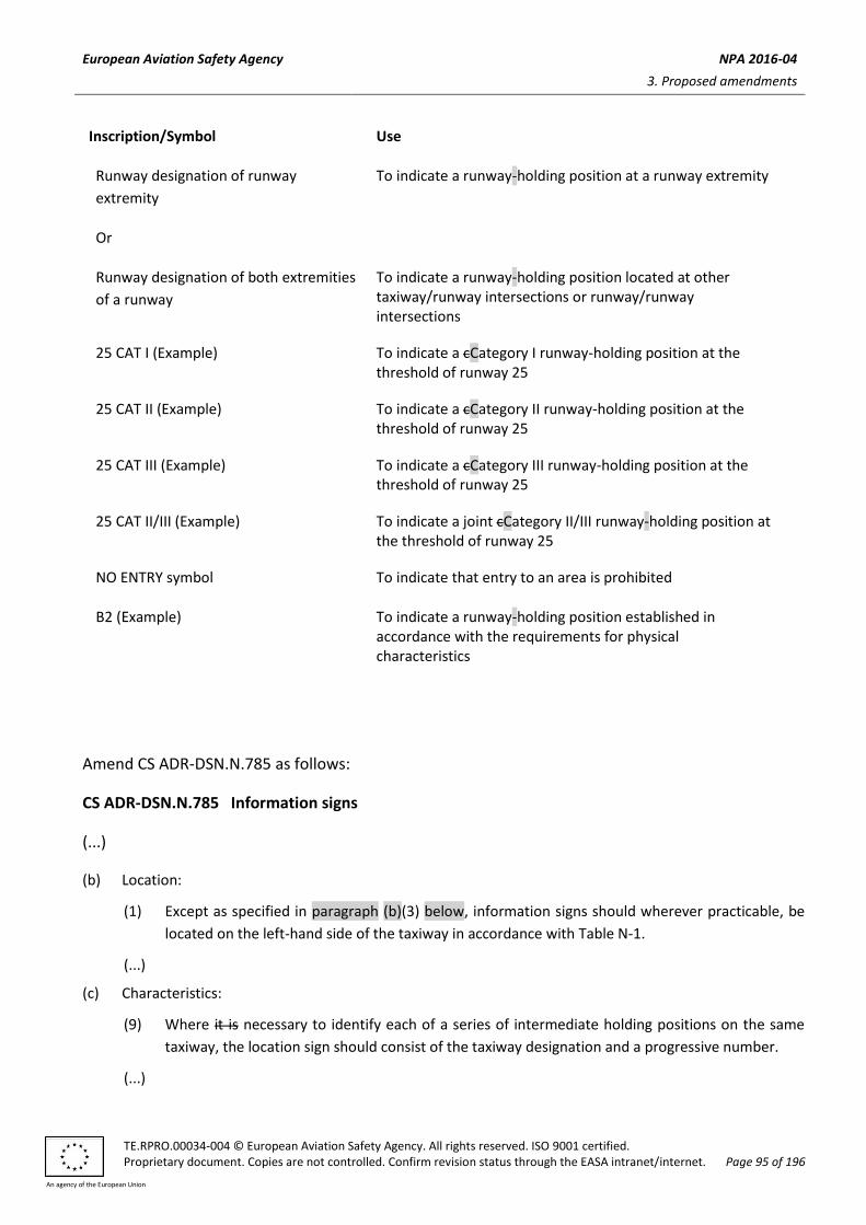
European Aviation Safety Agency NPA 2016-04
3. Proposed amendments
TE.RPRO.00034-004 © European Aviation Safety Agency. All rights reserved. ISO 9001 certified. Proprietary document. Copies are not controlled. Confirm revision status through the EASA intranet/internet. Page 95 of 196
An agency of the European Union
Inscription/Symbol Use
Runway designation of runway
extremity
To indicate a runway-holding position at a runway extremity
Or
Runway designation of both extremities
of a runway
To indicate a runway-holding position located at other taxiway/runway intersections or runway/runway intersections
25 CAT I (Example) To indicate a cCategory I runway-holding position at the threshold of runway 25
25 CAT II (Example) To indicate a cCategory II runway-holding position at the threshold of runway 25
25 CAT III (Example) To indicate a cCategory III runway-holding position at the threshold of runway 25
25 CAT II/III (Example) To indicate a joint cCategory II/III runway-holding position at the threshold of runway 25
NO ENTRY symbol To indicate that entry to an area is prohibited
B2 (Example) To indicate a runway-holding position established in accordance with the requirements for physical characteristics
Amend CS ADR-DSN.N.785 as follows:
CS ADR-DSN.N.785 Information signs
(...)
(b) Location:
(1) Except as specified in paragraph (b)(3) below, information signs should wherever practicable, be
located on the left-hand side of the taxiway in accordance with Table N-1.
(...)
(c) Characteristics:
(9) Where it is necessary to identify each of a series of intermediate holding positions on the same
taxiway, the location sign should consist of the taxiway designation and a progressive number.
(...)
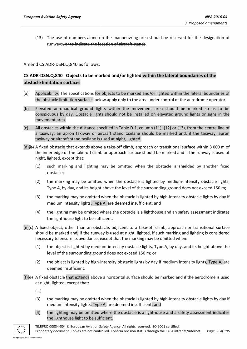
European Aviation Safety Agency NPA 2016-04
3. Proposed amendments
TE.RPRO.00034-004 © European Aviation Safety Agency. All rights reserved. ISO 9001 certified. Proprietary document. Copies are not controlled. Confirm revision status through the EASA intranet/internet. Page 96 of 196
An agency of the European Union
(13) The use of numbers alone on the manoeuvring area should be reserved for the designation of
runways, or to indicate the location of aircraft stands.
Amend CS ADR-DSN.Q.840 as follows:
CS ADR-DSN.Q.840 Objects to be marked and/or lighted within the lateral boundaries of the
obstacle limitation surfaces
(a) Applicability: The specifications for objects to be marked and/or lighted within the lateral boundaries of
the obstacle limitation surfaces below apply only to the area under control of the aerodrome operator.
(b) Elevated aeronautical ground lights within the movement area should be marked so as to be conspicuous by day. Obstacle lights should not be installed on elevated ground lights or signs in the movement area.
(c) All obstacles within the distance specified in Table D-1, column (11), (12) or (13), from the centre line of a taxiway, an apron taxiway or aircraft stand taxilane should be marked and, if the taxiway, apron taxiway or aircraft stand taxilane is used at night, lighted.
(d)(b) A fixed obstacle that extends above a take-off climb, approach or transitional surface within 3 000 m of the inner edge of the take-off climb or approach surface should be marked and if the runway is used at night, lighted, except that:
(1) such marking and lighting may be omitted when the obstacle is shielded by another fixed
obstacle;
(2) the marking may be omitted when the obstacle is lighted by medium-intensity obstacle lights,
Type A, by day, and its height above the level of the surrounding ground does not exceed 150 m;
(3) the marking may be omitted when the obstacle is lighted by high-intensity obstacle lights by day if
medium intensity lights, Type A, are deemed insufficient; and
(4) the lighting may be omitted where the obstacle is a lighthouse and an safety assessment indicates
the lighthouse light to be sufficient.
(e)(c) A fixed object, other than an obstacle, adjacent to a take-off climb, approach or transitional surface should be marked and, if the runway is used at night, lighted, if such marking and lighting is considered necessary to ensure its avoidance, except that the marking may be omitted when:
(1) the object is lighted by medium-intensity obstacle lights, Type A, by day, and its height above the
level of the surrounding ground does not exceed 150 m; or
(2) the object is lighted by high-intensity obstacle lights by day if medium intensity lights, Type A, are
deemed insufficient.
(f)(d) A fixed obstacle that extends above a horizontal surface should be marked and if the aerodrome is used at night, lighted, except that:
(...)
(3) the marking may be omitted when the obstacle is lighted by high-intensity obstacle lights by day if medium intensity lights, Type A, are deemed insufficient; and
(4) the lighting may be omitted where the obstacle is a lighthouse and a safety assessment indicates the lighthouse light to be sufficient.

European Aviation Safety Agency NPA 2016-04
3. Proposed amendments
TE.RPRO.00034-004 © European Aviation Safety Agency. All rights reserved. ISO 9001 certified. Proprietary document. Copies are not controlled. Confirm revision status through the EASA intranet/internet. Page 97 of 196
An agency of the European Union
(g)(e) A fixed object that extends above an obstacle protection surface should be marked and, if the runway is used at night, lighted, except that such marking and lighting may be omitted when the obstacle is shielded by another fixed obstacle.
(f) Elevated aeronautical ground lights within the movement area should be marked so as to be conspicuous by day. Obstacle lights should not be installed on elevated ground lights or signs in the movement area.
(g) All obstacles within the distance specified in Table D-1, from the centre line of a taxiway, an apron
taxiway, or aircraft stand taxilane should be marked and if the taxiway, apron taxiway or aircraft stand
taxilane is used at night, lighted.
Insert new CS ADR-DSN.Q.841 as follows:
CS ADR-DSN.Q.841 Objects to be marked and/or lighted outside the lateral boundaries of the
obstacle limitation surfaces
(a) Applicability: The specifications for objects to be marked and/or lighted outside the lateral boundaries
of the obstacle limitation surfaces apply only to the area under control of the aerodrome operator.
(b) Obstacles in accordance with CS ADR-DSN.J.487 should be marked and lighted, except that the marking
may be omitted when the obstacle is lighted by high-intensity obstacle lights by day.
(c) When considered as an obstacle, other objects outside the obstacle limitation surfaces should be
marked and/or lighted.
Amend CS ADR-DSN.Q.845 as follows:
CS ADR-DSN.Q.845 Marking of fixed objects
(a) General: All fixed objects to be marked should, whenever practicable, be coloured but if this is not practicable, markers or flags should be displayed on or above them, except those objects that are sufficiently conspicuous by their shape, size, or colour need not be otherwise marked.
(b) Marking by colour
(1) An object should be coloured to show a chequered pattern if it has essentially unbroken surfaces, and its projection on any vertical plane equals or exceeds 4.5 m in both dimensions. The pattern should consist of rectangles of not less than 1.5 m and not more than 3 m on a side, the corners being of the darker colour. The colours of the pattern should contrast with each other and with the background against which they should be seen.
(2) An object should be coloured to show alternating contrasting bands if:
(i) it has essentially unbroken surfaces, and has one dimension, horizontal or vertical, greater than 1.5 m, and the other dimension, horizontal or vertical, less than 4.5 m; or
(ii) it is of skeletal type with either a vertical or a horizontal dimension greater than 1.5 m.
(3) The bands should be perpendicular to the longest dimension and have a width approximately 1/7 of the longest dimension or 30 m, whichever is less. The colours of the bands should contrast with the background against which they should be seen. Orange and white should be used, except

European Aviation Safety Agency NPA 2016-04
3. Proposed amendments
TE.RPRO.00034-004 © European Aviation Safety Agency. All rights reserved. ISO 9001 certified. Proprietary document. Copies are not controlled. Confirm revision status through the EASA intranet/internet. Page 98 of 196
An agency of the European Union
where such colours are not conspicuous when viewed against the background. The bands on the extremities of the object should be of the darker colour (see Figures Q-1 and Q-2). The dimensions of the marking band widths are shown in Table Q-4.
(4) An object should be coloured in a single conspicuous colour if its projection on any vertical plane has both dimensions less than 1.5 m. Orange or red should be used, except where such colours merge with the background.
(c) Marking by flags
(1) Flags used to mark fixed objects should be displayed around, on top of, or around the highest edge of the object. When flags are used to mark extensive objects or groups of closely spaced objects, they should be displayed at least every 15 m. Flags should not increase the hazard presented by the object they mark.
(2) Flags used to mark fixed objects should not be less than 0.6 m on each side.
(3) Flags used to mark fixed objects should be orange in colour or a combination of two triangular sections, one orange and the other white, or one red and the other white. Except where such colours merge with the background, other conspicuous colours should be used.
(d) Marking by markers
(1) Markers displayed on or adjacent to objects should be located in conspicuous positions so as to retain the general definition of the object and should be recognisable in clear weather from a distance of at least 1 000 m for an object to be viewed from the air and 300 m for an object to be viewed from the ground in all directions in which an aircraft is likely to approach the object. The shape of markers should be distinctive to the extent necessary to ensure that they are not mistaken for markers employed to convey other information, and they should be such that the hazard presented by the object they mark is not increased.
(2) A marker should be of one colour. When more than one markers are installed, white and red, or white and orange markers should be displayed alternately. The colour selected should contrast with the background against which it should be seen.
(a) The specifications below apply only to the area under control of the aerodrome operator.
(b) All fixed objects to be marked should whenever practicable, be coloured but if this is not practicable, markers or flags should be displayed on or above them, except that objects that are sufficiently conspicuous by their shape, size, or colour need not be otherwise marked.
(c) Use of colours
(1) An object should be coloured to show a chequered pattern if it has essentially unbroken surfaces,
and its projection on any vertical plane equals or exceeds 4.5 m in both dimensions. The pattern
should consist of rectangles of not less than 1.5 m and not more than 3 m on a side, the corners
being of the darker colour. The colours of the pattern should contrast with each other and with
the background against which they should be seen.
(2) An object should be coloured to show alternating contrasting bands if:
(i) it has essentially unbroken surfaces, and has one dimension, horizontal or vertical, greater
than 1.5 m, and the other dimension, horizontal or vertical, less than 4.5 m; or
(ii) it is of skeletal type with either a vertical or a horizontal dimension greater than 1.5 m.
(3) The bands should be perpendicular to the longest dimension and have a width approximately 1/7
of the longest dimension or 30 m, whichever is less. The colours of the bands should contrast with

European Aviation Safety Agency NPA 2016-04
3. Proposed amendments
TE.RPRO.00034-004 © European Aviation Safety Agency. All rights reserved. ISO 9001 certified. Proprietary document. Copies are not controlled. Confirm revision status through the EASA intranet/internet. Page 99 of 196
An agency of the European Union
the background against which they should be seen. Orange and white should be used, except
where such colours are not conspicuous when viewed against the background. The bands on the
extremities of the object should be of the darker colour (see Figures Q-1 and Q-2). The dimensions
of the marking band widths are shown in Table Q-3.
(4) An object should be coloured in a single conspicuous colour if its projection on any vertical plane
has both dimensions less than 1.5 m. Orange or red should be used, except where such colours
merge with the background.
(d) Use of markers:
(1) Markers displayed on or adjacent to objects should be located in conspicuous positions so as to retain the general definition of the object and should be recognisable in clear weather from a distance of at least 1 000 m for an object to be viewed from the air and 300 m for an object to be viewed from the ground in all directions in which an aircraft is likely to approach the object. The shape of markers should be distinctive to the extent necessary to ensure that they are not mistaken for markers employed to convey other information, and they should be such that the hazard presented by the object they mark is not increased.
(2) Marker displayed on an overhead wire, cable, etc., should be spherical and have a diameter of not
less than 60 cm.
(3) The spacing between two consecutive markers, or between a marker and a supporting tower
should be appropriate to the diameter of the marker. The spacing should normally not exceed:
(i) 30 m where the marker diameter is 60 cm, increasing progressively with increase of the
marker diameter to:
(A) 35 m where the marker diameter is 80 cm; and
(B) further progressive increases to a maximum of 40 m where the marker diameter is of at least 130 cm.
Where multiple wires, cables, etc., are involved, a marker should be located not lower than the
level of the highest wire at the point marked.
(4) A marker should be of one colour. When installed, white and red, or white and orange markers should be displayed alternately. The colour selected should contrast with the background against which it should be seen.
(e) Use of flags
(1) Flags used to mark objects should be displayed around, on top of, or around the highest edge of,
the object. When flags are used to mark extensive objects or groups of closely spaced objects,
they should be displayed at least every 15 m. Flags should not increase the hazard presented by
the object they mark.
(2) Flags used to mark fixed objects should not be less than 0.6 m square.
(3) Flags used to mark fixed objects should be orange in colour or a combination of two triangular
sections, one orange and the other white, or one red and the other white, except that where such
colours merge with the background, other conspicuous colours should be used.
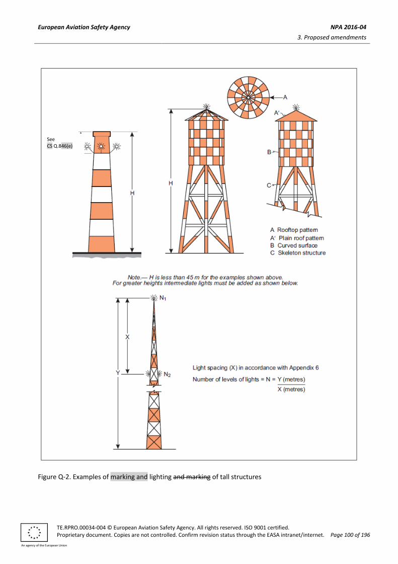
European Aviation Safety Agency NPA 2016-04
3. Proposed amendments
TE.RPRO.00034-004 © European Aviation Safety Agency. All rights reserved. ISO 9001 certified. Proprietary document. Copies are not controlled. Confirm revision status through the EASA intranet/internet. Page 100 of 196
An agency of the European Union
Figure Q-2. Examples of marking and lighting and marking of tall structures
See CS Q.846(e)

European Aviation Safety Agency NPA 2016-04
3. Proposed amendments
TE.RPRO.00034-004 © European Aviation Safety Agency. All rights reserved. ISO 9001 certified. Proprietary document. Copies are not controlled. Confirm revision status through the EASA intranet/internet. Page 101 of 196
An agency of the European Union
Insert new CS ADR-DSN.Q.846 as follows:
CS ADR-DSN.Q.846 Lighting of fixed objects
(a) The presence of objects which should be lighted, as specified in CS ADR-DSN.Q.840 and CS ADR-DSN.Q.841 should be indicated by low-, medium- or high-intensity obstacle lights, or a combination of such lights.
(b) Low-intensity obstacle lights, Types A, B, C and D, medium-intensity obstacle lights, Types A, B and C and high-intensity obstacle lights Types A and B, should be in accordance with the specifications in Table Q-1, CS ADR-DSN.U.930 and Figure U-1.
(c) The number and arrangement of low-, medium- or high-intensity obstacle lights at each level to be marked should be such that the object is indicated from every angle in azimuth. Where a light is shielded in any direction by another part of the object or by an adjacent object, additional lights should be provided on that adjacent object, or the part of the object that is shielding the light, in such a way as to retain the general definition of the object to be lighted. If the shielded light does not contribute to the definition of the object to be lighted, it may be omitted.
(d) In case of an object to be lighted one or more low-, medium- or high-intensity obstacle lights should be located as close as practicable to the top of the object.
(e) In the case of chimney or other structure of like function, the top lights should be placed sufficiently below the top so as to minimise contamination by smoke, etc. (see Figure Q-2).
(f) In the case of a tower or antenna structure indicated by high-intensity obstacle lights by day with an appurtenance such as a rod or an antenna greater than 12 m where it is not practicable to locate a high-intensity obstacle light on the top of the appurtenance, such a light should be located at the highest practicable point, and, if practicable, a medium-intensity obstacle light, Type A, mounted on the top.
(g) In the case of an extensive object or of a group of closely spaced objects to be lighted that are:
(1) Penetrating a horizontal obstacle limitation surface (OLS) or located outside an OLS, the top lights should be so arranged as to at least indicate the points or edges of the object highest in relation to OLS or above the ground, and so as to indicate the general definition and the extent of the objects; and
(2) Penetrating a sloping OLS, the top lights should be so arranged as to at least indicate the points or edges of the object highest in relation to the OLS, and so as to indicate the general definition and the extent of the objects. If two or more edges are of the same height, the edge nearest the landing area should be marked.
(h) When the obstacle limitation surface concerned is sloping and the highest point above the obstacle limitation surface is not the highest point of the object, additional obstacle lights should be placed on the highest point of the object.
(i) Where lights are applied to display the general definition of an extensive object or a group of closely spaced objects, and
(1) Low-intensity lights are used, they should be spaced at longitudinal intervals not exceeding 45 m.
(2) Medium-intensity lights are used, they should be spaced at longitudinal intervals not exceeding 900 m.
(j) High-intensity obstacle lights, Type A, and medium-intensity obstacle lights, Types A and B, located on an object should flash simultaneously.

European Aviation Safety Agency NPA 2016-04
3. Proposed amendments
TE.RPRO.00034-004 © European Aviation Safety Agency. All rights reserved. ISO 9001 certified. Proprietary document. Copies are not controlled. Confirm revision status through the EASA intranet/internet. Page 102 of 196
An agency of the European Union
(k) The installation setting angles for high-intensity obstacle lights, Type A, should be in accordance with
Table Q-5.
Insert new CS ADR-DSN.Q.847 as follows:
CS ADR-DSN.Q.847 Lighting of fixed objects with a height less than 45 m above ground level
(a) Low-intensity obstacle lights, Type A or B, should be used where the object is a less extensive one and its height above the surrounding ground is less than 45 m.
(b) Where the use of low-intensity obstacle lights, Type A or B, would be inadequate, or an early special warning is required, then medium- or high-intensity obstacle lights should be used.
(c) Low-intensity obstacle lights, Type B, should be used either alone or in combination with medium-intensity obstacle lights, Type B, in accordance with subparagraph (d), below.
(d) Medium-intensity obstacle lights, Type A, B, or C, should be used where the object is an extensive one. Medium-intensity obstacle lights, Types A and C, should be used alone, whereas medium-intensity obstacle lights, Type B, should be used either alone or in combination with low-intensity obstacle lights, Type B.
Insert new CS ADR-DSN.Q.848 as follows:
CS ADR-DSN.Q.848 Lighting of fixed objects with a height 45 m to a height less than 150 m above
ground level
(a) Medium-intensity obstacle lights, Type A, B, or C, should be used where the object is an extensive one.
Medium-intensity obstacle lights, Types A and C, should be used alone, whereas medium-intensity
obstacle lights, Type B, should be used either alone or in combination with low-intensity obstacle lights,
Type B.
(b) Where an object is indicated by medium-intensity obstacle lights, Type A, and the top of the object is
more than 105 m above the level of the surrounding ground, or the elevation of tops of nearby buildings
(when the object to be marked is surrounded by buildings), additional lights should be provided at
intermediate levels. These additional intermediate lights should be spaced, as equally as practicable,
between the top lights and ground level or the level of tops of nearby buildings as appropriate, with the
spacing not exceeding 105 m.
(c) Where an object is indicated by medium-intensity obstacle lights, Type B, and the top of the object is more than 45 m above the level of the surrounding ground or the elevation of tops of nearby buildings (when the object to be marked is surrounded by buildings), additional lights should be provided at intermediate levels. These additional intermediate lights should be alternately low-intensity obstacle lights, Type B, and medium-intensity obstacle lights, Type B, and should be spaced as equally as practicable, between the top lights and ground level or the level of tops of nearby buildings as appropriate, with the spacing not exceeding 52 m.
(d) Where an object is indicated by medium-intensity obstacle lights, Type C, and the top of the object is more than 45 m above the level of the surrounding ground or the elevation of tops of nearby buildings (when the object to be marked is surrounded by buildings), additional lights should be provided at intermediate levels. These additional intermediate lights should be spaced as equally as practicable,

European Aviation Safety Agency NPA 2016-04
3. Proposed amendments
TE.RPRO.00034-004 © European Aviation Safety Agency. All rights reserved. ISO 9001 certified. Proprietary document. Copies are not controlled. Confirm revision status through the EASA intranet/internet. Page 103 of 196
An agency of the European Union
between the top lights and ground level or the level of tops of nearby buildings, as appropriate, with the spacing not exceeding 52 m.
(e) Where high-intensity obstacle lights, Type A, are used, they should be spaced at uniform intervals not exceeding 105 m between the ground level and the top light(s) specified in paragraph CS ADR-DSN.Q.846(d), except that where an object to be marked is surrounded by buildings, the elevation of the tops of the buildings may be used as the equivalent of the ground level when determining the number of light levels.
Insert new CS ADR-DSN.Q.849 as follows:
CS ADR-DSN.Q.849 Lighting of fixed objects with a height 150 m or more above ground level
(a) High-intensity obstacle lights, Type A, should be used to indicate the presence of an object if its height above the level of the surrounding ground exceeds 150 m and a safety assessment indicates such lights to be essential for the recognition of the object by day.
(b) Where high-intensity obstacle lights, Type A, are used, they should be spaced at uniform intervals not exceeding 105 m between the ground level and the top light(s) specified in CS ADR-DSN.Q.846(d), except where an object to be marked is surrounded by buildings, the elevation of the tops of the buildings may be used as the equivalent of the ground level when determining the number of light levels.
(c) Where an object is indicated by medium-intensity obstacle lights, Type A, additional lights should be provided at intermediate levels. These additional intermediate lights should be spaced, as equally as practicable, between the top lights and ground level or the level of tops of nearby buildings, as appropriate, with the spacing not exceeding 105 m.
(d) Where an object is indicated by medium-intensity obstacle lights, Type B, additional lights should be provided at intermediate levels. These additional intermediate lights should be alternately low-intensity obstacle lights, Type B, and medium-intensity obstacle lights, Type B, and should be spaced, as equally as practicable, between the top lights and ground level or the level of tops of nearby buildings, as appropriate, with the spacing not exceeding 52 m.
(e) Where an object is indicated by medium-intensity obstacle lights, Type C, additional lights should be provided at intermediate levels. These additional intermediate lights should be spaced, as equally as practicable, between the top lights and ground level or the level of tops of nearby buildings, as appropriate, with the spacing not exceeding 52 m.

European Aviation Safety Agency NPA 2016-04
3. Proposed amendments
TE.RPRO.00034-004 © European Aviation Safety Agency. All rights reserved. ISO 9001 certified. Proprietary document. Copies are not controlled. Confirm revision status through the EASA intranet/internet. Page 104 of 196
An agency of the European Union
Figure Q-3. Lighting of buildings
Amend CS ADR-DSN.Q.850 as follows:
CS ADR-DSN.Q.850 Lighting of other objects
(a) Low-intensity obstacle lights, Type C, shall be displayed on vehicles and other mobile objects excluding aircraft.
(b)(3) Low-intensity obstacle lights, Type C, displayed on vehicles associated with emergency or security shall be flashing-blue and those displayed on other vehicles shall be flashing-yellow.
(c)(4) Low-intensity obstacle lights, Type D, shall be displayed on follow-me vehicles. (d)(6) Low-intensity obstacle lights on objects with limited mobility such as aerobridges shall be fixed-red, and,
as a minimum, be in accordance with the specifications for low-intensity obstacle lights, Type A, in Table Q-1. The intensity of the lights shall be sufficient to ensure conspicuity considering the intensity of the adjacent lights and the general levels of illumination against which they would normally be viewed.
(a) The specifications below apply only to the area under control of the aerodrome operator.
(b) Use of obstacle lights:
(1) The presence of objects which should be lighted, should be indicated by low-, medium- or high-
intensity obstacle lights, or a combination of such lights.
(2) Low-intensity obstacle lights, Type A or B, should be used where the object is a less extensive one
and its height above the surrounding ground is less than 45 m.
(3) Where the use of low-intensity obstacle lights, Type A or B would be inadequate, or an early
special warning is required, then medium- or high-intensity obstacle lights should be used.
(4) Low-intensity obstacle lights, Type B, should be used either alone or in combination with medium-
intensity obstacle lights, Type B, in accordance with subparagraph (d) below.

European Aviation Safety Agency NPA 2016-04
3. Proposed amendments
TE.RPRO.00034-004 © European Aviation Safety Agency. All rights reserved. ISO 9001 certified. Proprietary document. Copies are not controlled. Confirm revision status through the EASA intranet/internet. Page 105 of 196
An agency of the European Union
(5) Medium-intensity obstacle lights, Type A, B, or C, should be used where the object is an extensive
oneor its height above the level of the surrounding ground is greater than 45 m. Medium-
intensity obstacle lights, Types A and C, should be used alone, whereas medium-intensity obstacle
lights, Type B, should be used either alone or in combination with low-intensity obstacle lights,
Type B.
(6) High-intensity obstacle lights, Type A, should be used to indicate the presence of an object if its
height above the level of the surrounding ground exceeds 150 m and an safety assessment
indicates such lights to be essential for the recognition of the object by day.
(7) When a dual obstacle lighting system is provided, the system should be composed of high-
intensity obstacle lights, Type A, or B, or medium-intensity obstacle lights, Type A, as appropriate,
for daytime and twilight use and medium-intensity obstacle lights, Type B or C, for night-time use.
(c) Location of obstacle lights:
(1) One or more low-, medium- or high-intensity obstacle lights should be located as close as
practicable to the top of the object. The top lights should be so arranged as to at least indicate the
points or edges of the object highest in relation to the obstacle limitation surface.
(2) In the case of chimney or other structure of like function, the top lights should be placed
sufficiently below the top so as to minimise contamination by smoke, etc. (see Figures Q-2 and Q-
3).
(3) In the case of a tower or antenna structure indicated by high-intensity obstacle lights by day with
an appurtenance, such as a rod or an antenna, greater than 12 m where it is not practicable to
locate a high-intensity obstacle light on the top of the appurtenance, such a light should be
located at the highest practicable point, and if practicable, a medium-intensity obstacle light, Type
A, mounted on the top.
(4) In the case of an extensive object or of a group of closely spaced objects, top lights should be
displayed at least on the points or edges of the objects highest in relation to the obstacle
limitation surface so as to indicate the general definition and the extent of the objects. If two or
more edges are of the same height, the edge nearest the landing area should be marked. Where
low-intensity lights are used, they should be spaced at longitudinal intervals not exceeding 45 m.
Where medium-intensity lights are used, they should be spaced at longitudinal intervals not
exceeding 900 m.
(5) When the obstacle limitation surface concerned is sloping and the highest point above the
obstacle limitation surface is not the highest point of the object, additional obstacle lights should
be placed on the highest point of the object.
(6) Where an object is indicated by medium-intensity obstacle lights, Type A, and the top of the
object is more than 105 m above the level of the surrounding ground, or the elevation of tops of
nearby buildings (when the object to be marked is surrounded by buildings), additional lights
should be provided at intermediate levels. These additional intermediate lights should be spaced
as equally as practicable, between the top lights and ground level or the level of tops of nearby
buildings as appropriate, with the spacing not exceeding 105 m (see subparagraph (b)(5) above).
(7) Where an object is indicated by medium-intensity obstacle lights, Type B, and the top of the
object is more than 45 m above the level of the surrounding ground or the elevation of tops of

European Aviation Safety Agency NPA 2016-04
3. Proposed amendments
TE.RPRO.00034-004 © European Aviation Safety Agency. All rights reserved. ISO 9001 certified. Proprietary document. Copies are not controlled. Confirm revision status through the EASA intranet/internet. Page 106 of 196
An agency of the European Union
nearby buildings (when the object to be marked is surrounded by buildings), additional lights
should be provided at intermediate levels. These additional intermediate lights should be
alternately low-intensity obstacle lights, Type B, and medium-intensity obstacle lights, Type B, and
should be spaced as equally as practicable, between the top lights and ground level or the level of
tops of nearby buildings as appropriate, with the spacing not exceeding 52 m.
(8) Where an object is indicated by medium-intensity obstacle lights, Type C, and the top of the
object is more than 45 m above the level of the surrounding ground or the elevation of tops of
nearby buildings (when the object to be marked is surrounded by buildings), additional lights
should be provided at intermediate levels. These additional intermediate lights should be spaced
as equally as practicable, between the top lights and ground level or the level of tops of nearby
buildings as appropriate, with the spacing not exceeding 52 m.
(9) Where high-intensity obstacle lights, Type A, are used, they should be spaced at uniform intervals
not exceeding 105 m between the ground level and the top light(s) specified in paragraph (c)(1)
above, except that where an object to be marked is surrounded by buildings, the elevation of the
tops of the buildings may be used as the equivalent of the ground level when determining the
number of light levels.
(10) Where high-intensity obstacle lights, Type B, are used, they should be located at three levels:
(i) at the top of the tower;
(ii) at the lowest level of the catenary of the wires or cables; and
(iii) at approximately midway between these two levels.
(11) The installation setting angles for high-intensity obstacle lights, Types A and B, should be in accordance with Table Q-1.
(12) The number and arrangement of low-, medium- or high-intensity obstacle lights at each level to be marked should be such that the object is indicated from every angle in azimuth. Where a light is shielded in any direction by another part of the object, or by an adjacent object, additional lights should be provided on that object in such a way as to retain the general definition of the object to be lighted. If the shielded light does not contribute to the definition of the object to be lighted, it may be omitted.
(d) Low-intensity obstacle lights — Characteristics:
(1) Low-intensity obstacle lights on fixed objects, Types A and B, should be fixed-red lights.
(2) Low-intensity obstacle lights, Types A and B, should be in accordance with the specifications in
Table Q-2.
(3) (3) Low-intensity obstacle lights, Types C and D, should be in accordance with the specifications in
Table Q-2.
(5) Low-intensity obstacle lights on objects with limited mobility should as a minimum be in accordance with the specifications for low-intensity obstacle lights, Type A, in Table Q-2.
(e) Medium-intensity obstacle lights — Characteristics:
(1) Medium-intensity obstacle lights, Type A, should be flashing-white lights, Type B should be
flashing-red lights, and Type C should be fixed-red lights.

European Aviation Safety Agency NPA 2016-04
3. Proposed amendments
TE.RPRO.00034-004 © European Aviation Safety Agency. All rights reserved. ISO 9001 certified. Proprietary document. Copies are not controlled. Confirm revision status through the EASA intranet/internet. Page 107 of 196
An agency of the European Union
(2) Medium-intensity obstacle lights, Types A, B and C, should be in accordance with the
specifications in Table Q-2.
(3) Medium-intensity obstacle lights, Types A and B, located on an object should flash simultaneously.
(f) High-intensity obstacle lights — Characteristics:
(1) High-intensity obstacle lights, Types A and B, should be flashing-white lights.
(2) High-intensity obstacle lights, Types A and B, should be in accordance with the specifications in
Table Q-2.
(3) High-intensity obstacle lights, Type A, located on an object should flash simultaneously.
(4) High-intensity obstacle lights, Type B, indicating the presence of a tower supporting overhead wires, cables, etc., should flash sequentially; first the middle light, second the top light, and last the bottom light. The intervals between flashes of the lights should approximate the following ratios:
Flash interval between Ratio of cycle time
Middle and top light 1:13
Top and bottom light 2:13
Bottom and middle light 10:13
Insert new CS ADR-DSN.Q.851 as follows:
CS ADR-DSN.Q.851 Marking and lighting of wind turbines
(1) Applicability: When considered as an obstacle a wind turbine should be marked and/or lighted.
(2) Marking: The rotor blades, nacelle and upper 2/3 of the supporting mast of wind turbines should be
painted white, or if after safety assessment, it is determined that other colour will improve safety.
(3) Lighting:
(1) Where lighting is deemed necessary for a single wind turbine or short line of wind turbines, the
installation should be in accordance with paragraph (c)(2)(v) below, or as determined by a safety
assessment.
(2) When lighting is deemed necessary in the case of a wind farm (i.e. a group of two or more wind
turbines), the wind farm should be regarded as an extensive object and lights should be installed:
(i) to identify the perimeter of the wind farm;
(ii) respecting the maximum spacing, in accordance with CS ADR-DSN.Q.846(i), between the
lights along the perimeter, or if after safety assessment, it is determined that a greater
spacing can be used;
(iii) so that, where flashing lights are used, they flash simultaneously throughout the wind farm;
(iv) so that, within a wind farm, any wind turbines of significantly higher elevation are also
identified wherever they are located; and
(v) at locations prescribed in (i), (ii) and (iv):

European Aviation Safety Agency NPA 2016-04
3. Proposed amendments
TE.RPRO.00034-004 © European Aviation Safety Agency. All rights reserved. ISO 9001 certified. Proprietary document. Copies are not controlled. Confirm revision status through the EASA intranet/internet. Page 108 of 196
An agency of the European Union
(A) for wind turbines of less than 150 m in overall height (hub height plus vertical blade
height), medium intensity lighting on the nacelle;
(B) for wind turbines from 150 m to 315 m in overall height, in addition to the medium
intensity light installed on the nacelle, a second light serving as an alternate should
be provided in case of failure of the operating light; the lights should be installed to
assure that the output of either light is not blocked by the other;
(C) in addition, for wind turbines from 150 m to 315 m in overall height, an intermediate
level at half the nacelle height of at least three low intensity Type E lights, as
specified in CS ADR-DSN.Q.846(c), that are configured to flash at the same rate as the
light on the nacelle; low-intensity Type A or B lights may be used if an safety
assessment shows that low intensity Type E lights are not suitable.
(3) The obstacle lights should be installed on the nacelle in such a manner as to provide an
unobstructed view for aircraft approaching from any direction.
Insert new CS ADR-DSN.Q.852 as follows:
CS ADR-DSN.Q.852 Marking and lighting of overhead wires, cables, supporting towers, etc.
(a) Marking: The wires, cables, etc. to be marked should be equipped with markers; the supporting tower should be coloured.
(b) Marking by colours: The supporting towers of overhead wires, cables, etc. that require marking should be marked in accordance with CS ADR-DSN.Q.845(b), except that the marking of the supporting towers may be omitted when they are lighted by high-intensity obstacle lights by day.
(c) Marking by markers:
(1) Markers displayed on or adjacent to objects should be located in conspicuous positions so as to retain the general definition of the object and should be recognisable in clear weather from a distance of at least 1 000 m for an object to be viewed from the air and 300 m for an object to be viewed from the ground in all directions in which an aircraft is likely to approach the object. The shape of markers should be distinctive to the extent necessary to ensure that they are not mistaken for markers employed to convey other information, and they should be such that the hazard presented by the object they mark is not increased.
(2) A marker displayed on an overhead wire, cable, etc., should be spherical and have a diameter of not less than 60 cm.
(3) The spacing between two consecutive markers, or between a marker and a supporting tower, should be appropriate to the diameter of the marker. The spacing should normally not exceed:
(i) 30 m where the marker diameter is 60 cm, increasing progressively with increase of the marker diameter to:
(ii) 35 m where the marker diameter is 80 cm; and
(iii) further progressive increases to a maximum of 40 m where the marker diameter is of at least 130 cm.
Where multiple wires, cables, etc., are involved, a marker should be located not lower than the level of the highest wire at the point marked.

European Aviation Safety Agency NPA 2016-04
3. Proposed amendments
TE.RPRO.00034-004 © European Aviation Safety Agency. All rights reserved. ISO 9001 certified. Proprietary document. Copies are not controlled. Confirm revision status through the EASA intranet/internet. Page 109 of 196
An agency of the European Union
(4) A marker should be of one colour. When installed, white and red, or white and orange, markers should be displayed alternately. The colour selected should contrast with the background against which it should be seen.
(5) When it has been determined that an overhead wire, cable, etc., needs to be marked but it is not practicable to install markers on the wire, cable, etc., then high-intensity obstacle lights, Type B, should be provided on their supporting towers.
(d) Lighting:
(1) High-intensity obstacle lights, Type B, should be used to indicate the presence of the tower supporting overhead wires, cables, etc. where:
(i) a safety assessment indicates such light to be essential for the recognition of the presence of wires, cables, etc.; or
(ii) it has not been found practicable to install marker on the wires, cables, etc.
(2) Where high-intensity obstacle lights, Type B, are used, they should be located at three levels:
(i) at the top of the tower;
(ii) at the lowest level of the catenary of the wires or cables; and
(iii) at approximately midway between these two levels.
(3) High-intensity obstacle lights, Type B, indicating the presence of a tower supporting overhead wires, cables, etc., should flash sequentially; first the middle light, second the top light, and last the bottom light. The intervals between flashes of the lights should approximate the following ratios:
Flash interval between Ratio of cycle time
Middle and top light 1/13
Top and bottom light 2/13
Bottom and middle light 10/13
(4) The installation setting angles for high-intensity obstacle lights, Types B, should be in accordance
with Table Q-5.
[Editorial Note: Insert new Table Q-1]
1 2 3 4 5 6 7
Light type Colour
Signal type/
(Flash Rate)
Peak intensity (cd) at given Background
Luminance (b)
Light
Distribution
Table
Day (Above
500 cd/m2)
Twilight (50-
500 cd/m2)
Night
(Below 50
cd/m2)
Low-intensity
Type A (fixed
obstacle)
Red Fixed N/A N/A 10 Table Q-2
Low-intensity
Type B (fixed
obstacle)
Red Fixed N/A N/A 32 Table Q-2
Low-intensity
Type C
(mobile
Yellow/
Blue
(a)
Flashing
(60-90
fpm)
N/A 40 40 Table Q-2

European Aviation Safety Agency NPA 2016-04
3. Proposed amendments
TE.RPRO.00034-004 © European Aviation Safety Agency. All rights reserved. ISO 9001 certified. Proprietary document. Copies are not controlled. Confirm revision status through the EASA intranet/internet. Page 110 of 196
An agency of the European Union
obstacle)
Low-intensity
Type D
(follow-me
vehicle)
Yellow
Flashing
(60-90
fpm)
N/A 200 200 Table Q-2
Medium-
intensity Type
A
White
Flashing
(20-60
fpm)
20 000 20 000 2 000 Table Q-3
Medium-
intensity Type
B
Red
Flashing
(20-60
fpm)
N/A N/A 2 000 Table Q-3
Medium-
intensity Type
C
Red Fixed N/A N/A 2 000 Table Q-3
High-intensity
Type A White
Flashing
(40-60
fpm)
200 000 20 000 2 000 Table Q-3
High-intensity
Type B White
Flashing
(40-60
fpm)
100 000 20 000 2 000 Table Q-3
(a) CS ADR-DSN.Q.850(b)
(b) For flashing lights, effective intensity as determined in accordance with ICAO Doc 9157,
Aerodrome Design Manual, Part 4, Visual Aids.
(c) For wind turbine application, to flash at the same rate as the lighting on the nacelle.
Table Q-1. Characteristics of obstacle lights [Editorial Note: Insert new Table Q-2]
Minimum intensity
(a)
Maximum intensity
(a)
Vertical beam spread
(f)
Minimum beam spread
Intensity
Type A 10 cd (b) N/A 10° 5 cd
Type B 32 cd (b) N/A 10° 16 cd
Type C 40 cd (b) 400 cd 12(d) 20 cd
Type D 200 cd (c) 400 cd N/A(e) N/A
Note: This table does not include recommended horizontal beam spreads. CS ADR-DSN.Q.846(c) requires 360° coverage around an obstacle. Therefore, the number of lights needed to meet this requirement will depend on the horizontal beam spreads of each light as well as the shape of the obstacle. Thus, with narrower beam spreads, more lights will be required.
(a) 360° horizontal. For flashing lights, the intensity is read into effective intensity, as determined in
accordance with ICAO, Aerodrome Design Manual, Part 4, Visual Aids.
(b) Between 2 and 10° vertical. Elevation vertical angles are referenced to the horizontal when the light is
levelled.
(c) Between 2 and 20° vertical. Elevation vertical angles are referenced to the horizontal when the light is

European Aviation Safety Agency NPA 2016-04
3. Proposed amendments
TE.RPRO.00034-004 © European Aviation Safety Agency. All rights reserved. ISO 9001 certified. Proprietary document. Copies are not controlled. Confirm revision status through the EASA intranet/internet. Page 111 of 196
An agency of the European Union
levelled.
(d) Peak intensity should be located at approximately 2.5° vertical.
(e) Peak intensity should be located at approximately 17° vertical.
(f) Beam spread is defined as the angle between the horizontal plan and the directions for which the
intensity exceeds that mentioned in the ‘intensity’ column.
Table Q-2. Light distribution for low-intensity obstacle lights
[Editorial Note: Insert new Table Q-3] Benchmark
intensity
Minimum requirements Recommendations
Vertical elevation angle (b) Vertical beam
spread (c)
Vertical elevation angle (b) Vertical beam
spread (c) 0° -1° 0° -1° -10°
Minimum
average
intensity
(a)
Minimum
intensity
(a)
Minimum
intensity
(a)
Minimum
beam
spread
Intensity
(a)
Maximum
intensity
(a)
Maximum
intensity
(a)
Maximum
intensity
(a)
Maximum
beam
spread
Intensity
(a)
200 000 200 000 150 000 75 000 3° 75 000 250 000 112 500 7 500 7° 75 000
100 000 100 000 75 000 37 500 3° 37 500 125 000 56 250 3 750 7° 37 500
20 000 20 000 15 000 7 500 3° 7 500 25 000 11 250 750 N/A N/A
2 000 2 000 1 500 750 3° 750 2 500 1 25 75 N/A N/A
Note: This table does not include recommended horizontal beam spreads. CS ADR-DSN.Q.846(c) requires 360°
coverage around an obstacle. Therefore, the number of lights needed to meet this requirement will depend on the
horizontal beam spreads of each light as well as the shape of the obstacle. Thus, with narrower beam spreads, more
lights will be required.
(a) 360° horizontal. All intensities are expressed in Candela. For flashing lights, the intensity is read into effective
intensity, as determined in accordance with ICAO Doc 9157, Aerodrome Design Manual, Part 4, Visual Aids.
(b) Elevation vertical angles are referenced to the horizontal when the light unit is levelled.
(c) Beam spread is defined as the angle between the horizontal plan and the directions for which the intensity
exceeds that mentioned in the ‘intensity’ column.
Note: an extended beam spread may be necessary under specific configuration and justified by an aeronautical study.
Table Q-3. Light distribution for medium- and high-intensity obstacle lights according to benchmark intensities of Table Q-1
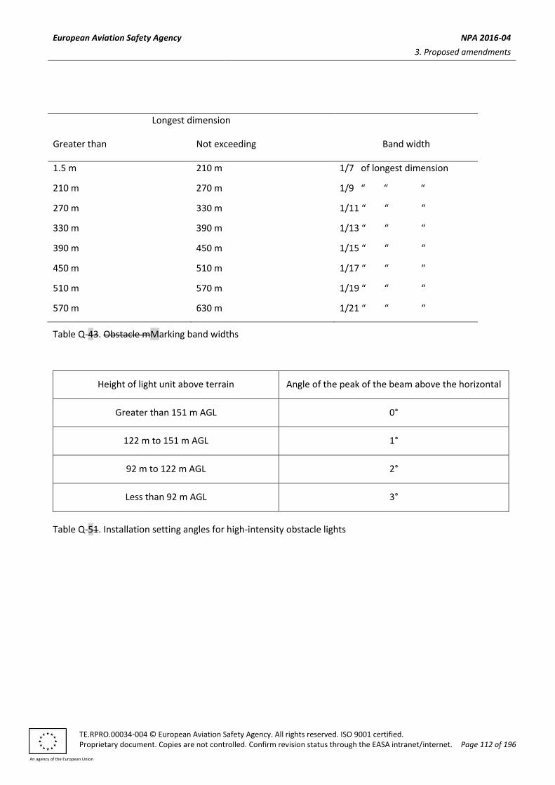
European Aviation Safety Agency NPA 2016-04
3. Proposed amendments
TE.RPRO.00034-004 © European Aviation Safety Agency. All rights reserved. ISO 9001 certified. Proprietary document. Copies are not controlled. Confirm revision status through the EASA intranet/internet. Page 112 of 196
An agency of the European Union
Longest dimension
Greater than Not exceeding Band width
1.5 m 210 m 1/7 of longest dimension
210 m 270 m 1/9 “ “ “
270 m 330 m 1/11 “ “ “
330 m 390 m 1/13 “ “ “
390 m 450 m 1/15 “ “ “
450 m 510 m 1/17 “ “ “
510 m 570 m 1/19 “ “ “
570 m 630 m 1/21 “ “ “
Table Q-43. Obstacle mMarking band widths
Height of light unit above terrain Angle of the peak of the beam above the horizontal
Greater than 151 m AGL 0°
122 m to 151 m AGL 1°
92 m to 122 m AGL 2°
Less than 92 m AGL 3°
Table Q-51. Installation setting angles for high-intensity obstacle lights

European Aviation Safety Agency NPA 2016-04
3. Proposed amendments
TE.RPRO.00034-004 © European Aviation Safety Agency. All rights reserved. ISO 9001 certified. Proprietary document. Copies are not controlled. Confirm revision status through the EASA intranet/internet. Page 113 of 196
An agency of the European Union
1 2 3 4 5 6 7 8 9 10 11 12
Light type Colour Signal type/flash rate
Peak intensity (cd) at given background luminance Vertical
beam spread
a
Intensity (cd) at given elevation angles when the light unit is levelled
d
Above 500 cd/m
2
50-500 cd/m2
Below 50 cd/m
2 -10°
e -1°
f ±0°
f +6° +10°
Low-intensity Type A (fixed obstacle)
Red Fixed N/A 10 mnm 10 mnm 10° ― ― ― 10 mnm g 10 mnm
g
Low-intensity Type B (fixed obstacle)
Red Fixed N/A 32 mnm 32 mnm 10° ― ― ― 32 mnm g 32 mnm
g
Low-intensity Type C (mobile obstacle)
Yellow/blue a
Flashing (60-90 fpm) N/A 40 mnm
b
400 max 40 mnm
b
400 max 12°
h ― ― ― ― ―
Low-intensity Type D (follow-me vehicle)
Yellow Flashing (60-90 fpm) N/A 200 mnm
b
400 max
200 mnm b
400 max 12°
i ― ― ― ― ―
Medium-intensity Type A White Flashing (20-60 fpm) 20 000
b
±25 % 20 000
b
±25 % 2 000
b
±25 % 3° mnm 3°% max
50 % mnm
75 % max
100 % mnm
― ―
Medium-intensity Type B Red Flashing (20-60 fpm) N/A N/A 2 000
b
±25% 3° mnm ―
50 % mnm
75 % max
100 % mnm
― ―
Medium-intensity Type C Red Fixed N/A N/A 2 000
b
±25% 3° mnm ―
50 % mnm
75 % max
100 % mnm
― ―
High-intensity Type A White Flashing (40-60 fpm) 200 000
b
±25% 20 000
b
±25% 2 000
b
±25% 3°-7° 3°% max
50 % mnm
75 % max
100 % mnm
― ―

European Aviation Safety Agency NPA 2016-04
3. Proposed amendments
TE.RPRO.00034-004 © European Aviation Safety Agency. All rights reserved. ISO 9001 certified. Proprietary document. Copies are not controlled. Confirm revision status through the EASA intranet/internet. Page 114 of 196
An agency of the European Union
High-intensity Type B White Flashing (40-60 fpm) 100 000
b
±25% 20 000
b
±25% 2 000
b
±25% 3°-7° 3°% max
50 % mnm
75 % max
100 % mnm
― ―
a CS ADR.DSN.Q.850, (d) (3)
b Effective intensity as determined in accordance with the ICAO Doc 9157, Aerodrome Design Manual, Part 4, Visual Aids.
c Beam spread is defined as the angle between two directions in a plane for which the intensity is equal to 50 % of the lower tolerance value of the intensity shown in columns 4,
5, and 6. The beam pattern is not necessarily symmetrical about the elevation angle at which the peak intensity occurs. d Elevation (vertical) angles are referenced to the horizontal.
e Intensity at any specified horizontal radial as a percentage of the actual peak intensity at the same radial when operated at each of the intensities shown columns 4, 5, and 6.
f Intensity at any specified horizontal radial as a percentage of the lower tolerance value of the intensity shown in columns 4, 5, and 6.
g In addition to specified values, lights should have sufficient intensity to ensure conspicuity at elevation angles between ±0° and 50°.
h Peak intensity should be located at approximately 2.5° vertical.
i Peak intensity should be located at approximately 17° vertical.
fpm = flashes per minute; N/A = not applicable
Table Q-2. Characteristics of obstacle lights
[Editorial Note: Delete existing Table Q-2]

European Aviation Safety Agency NPA 2016-04
3. Proposed amendments
TE.RPRO.00034-004 © European Aviation Safety Agency. All rights reserved. ISO 9001 certified. Proprietary document. Copies are not controlled. Confirm revision status through the EASA intranet/internet. Page 115 of 196
An agency of the European Union
Amend CS ADR-DSN.R.855 as follows:
CS ADR-DSN.R.855 Closed runways and taxiways, or parts thereof
(a) Applicability of closed marking:
(1) A closed marking should be displayed on a runway, or taxiway, or portion thereof which is permanently closed to the use of all aircraft.
(2) A closed marking should be displayed on a temporarily closed runway, or taxiway, or portion thereof, except that such marking may be omitted when the closing is of short duration, and adequate warning by air traffic services is provided.
(...)
(c) Characteristics of closed markings: (1)The closed marking should be of the form and proportions as detailed in Figure R-1, Illustration (a), when displayed on a runway, and should be of the form and proportions as detailed in Figure R-1, Illustration (b), when displayed on a taxiway. The marking should be white when displayed on a runway and should be yellow when displayed on a taxiway.
(d)(2) When a runway, or taxiway, or portion thereof is permanently closed, all normal runway and taxiway markings should be obliterated.
(d) Lighting on a closed runway, or taxiway, or portion thereof should not be operated, except as required for maintenance purposes.
(...)
Amend CS ADR-DSN.R.860 as follows:
CS ADR-DSN.R.860 Non-load-bearing surfaces
(a) Shoulders for taxiways, runway turn pads, holding bays and aprons, and other non-load-bearing surfaces which cannot readily be distinguished from load-bearing surfaces and which, if used by aircraft, might result in damage to the aircraft, should have the boundary between such areas and the load-bearing surface marked by a taxi side stripe marking (specifications for markings are in CS ADR-DSN.L.550).
(...)
Amend CS ADR-DSN.S.880 as follows:
CS ADR-DSN.S.880 Electrical power supply systems for visual aids
(...)
(c) At an aerodrome where the primary runway is a non-precision approach runway, a secondary power supply capable of meeting the requirements of Table S-1 should be provided except that a secondary power supply for visual aids need not be provided for more than one non-precision approach runway.
(...)
[Editorial Note: Insert new Table S-1]

European Aviation Safety Agency NPA 2016-04
3. Proposed amendments
TE.RPRO.00034-004 © European Aviation Safety Agency. All rights reserved. ISO 9001 certified. Proprietary document. Copies are not controlled. Confirm revision status through the EASA intranet/internet. Page 116 of 196
An agency of the European Union
Runway Lighting aids requiring power Maximum switc-hover time
Non-instrument
Visual approach slope indicatorsa
Runway edgeb
Runway thresholdb
Runway endb
Obstaclea
See
CS ADR-DSN.M.875(d) and
CS ADR-DSN.M.880(d)
Non-precision approach
Approach lighting system
Visual approach slope indicatorsa, d
Runway edged
Runway thresholdd
Runway endd
Obstaclea
15 seconds
15 seconds
15 seconds
15 seconds
15 seconds
15 seconds
Precision approach Category I
Approach lighting system
Runway edged
Visual approach slope indicatorsa, d
Runway thresholdd
Runway end
Essential taxiwaya
Obstaclea
15 seconds
15 seconds
15 seconds
15 seconds
15 seconds
15 seconds
15 seconds
Precision approach Category II/III
Inner 300 m of the approach lighting system
Other parts of the approach lighting system
Obstaclea
Runway edge
Runway threshold
Runway end
Runway centre line
Runway touchdown zone
All stop bars
Essential taxiway
1 second
15 seconds
15 seconds
15 seconds
1 second
1 second
1 second
1 second
1 second
15 seconds
Runway meant for take-off in runway visual range
conditions less than a value of 800 m
Runway edge
Runway end
Runway centre line
All stop bars
Essential taxiwaya
Obstaclea
15 seconds
1 second
1 second
1 second
15 seconds
15 seconds

European Aviation Safety Agency NPA 2016-04
3. Proposed amendments
TE.RPRO.00034-004 © European Aviation Safety Agency. All rights reserved. ISO 9001 certified. Proprietary document. Copies are not controlled. Confirm revision status through the EASA intranet/internet. Page 117 of 196
An agency of the European Union
Table S-1. Secondary power supply requirements
Amend CS ADR-DSN.S.890 as follows:
CS ADR-DSN.S.890 Monitoring
(...)
(d) For a runway meant for use in runway visual range conditions less than a value of 550 m, the lighting
systems detailed in Table S-1 should be monitored automatically so as to provide an indication when
the serviceability level of any element falls below a minimum serviceability level specified in
CS ADR-DSN.S.895(c) to (g). This information should be automatically relayed to the maintenance
crew.
(e) For a runway meant for use in runway visual range conditions less than a value of 550 m, the lighting
systems detailed in Table S-1 should be monitored automatically to provide an indication when the
serviceability level of any element falls below a minimum level specified in CS ADR-DSN.S.895, below
which operations should not continue. This information should be automatically relayed to the air
traffic services unit and displayed in a prominent position.
Amend CS ADR-DSN.S.895 as follows:
CS ADR-DSN.S.895 Serviceability levels
(...)
(c) The system of preventive maintenance employed for a precision approach runway cCategory II or III
should have as its objective that, during any period of cCategory II or III operations, all approach and
runway lights are serviceable and that, in any event, at least:
(1) 95 % of the lights are serviceable in each of the following particular significant elements:
(i) precision approach cCategory II and III lighting system, the inner 450 m;
(ii) runway centre line lights;
(iii) runway threshold lights; and
(iv) runway edge lights.
(...)
(...)
a. Supplied with secondary power when their operation is essential to the safety of flight operation.
b. The use of emergency lighting should be in accordance with any procedures established.
c. One second where no runway centre line lights are provided. d. One second where approaches are over hazardous or precipitous terrain.

European Aviation Safety Agency NPA 2016-04
3. Proposed amendments
TE.RPRO.00034-004 © European Aviation Safety Agency. All rights reserved. ISO 9001 certified. Proprietary document. Copies are not controlled. Confirm revision status through the EASA intranet/internet. Page 118 of 196
An agency of the European Union
(f) The system of preventive maintenance employed for a precision approach runway cCategory I should
have as its objective that, during any period of cCategory I operations, all approach and runway lights
are serviceable and that, in any event, at least 85 % of the lights are serviceable in each of the
following:
(1) precision approach cCategory I lighting system;
(2) runway threshold lights;
(3) runway edge lights; and
(4) runway end lights.
In order to provide continuity of guidance an unserviceable light should not be permitted adjacent to another unserviceable light unless the light spacing is significantly less than that specified.
(...)

European Aviation Safety Agency NPA 2016-04
3. Proposed amendments
TE.RPRO.00034-004 © European Aviation Safety Agency. All rights reserved. ISO 9001 certified. Proprietary document. Copies are not controlled. Confirm revision status through the EASA intranet/internet. Page 119 of 196
An agency of the European Union
Runway Lighting aids requiring power Maximum switch-over
time
Non-instrument
Visual approach slope indicatorsa
Runway edgeb
Runway thresholdb
Runway endb
Obstaclea
See CS ADR-DSN.M.875(d) and CS ADR-DSN.M.880(d)
Non-precision approach
Approach lighting system
Visual approach slope indicatorsa, d
Runway edged
Runway thresholdd
Runway endd
Obstaclea
15 seconds
15 seconds
15 seconds
15 seconds
15 seconds
15 seconds
Precision approach category I
Approach lighting system
Runway edged
Visual approach slope indicatorsa, d
Runway thresholdd
Runway end
Essential taxiwaya
Obstaclea
15 seconds
15 seconds
15 seconds
15 seconds
15 seconds
15 seconds
15 seconds
Precision approach category II/III
Inner 300 m of the approach lighting system
Other parts of the approach lighting system
Obstaclea
Runway edge
Runway threshold
Runway end
Runway centre line
Runway touchdown zone
All stop bars
Essential taxiway
1 second
15 seconds
15 seconds
15 seconds
1 second
1 second
1 second
1 second
1 second
15 seconds
Runway meant for take-off in runway visual range conditions less than a value of 800 m
Runway edge
Runway end
Runway centre line
All stop bars
Essential taxiwaya
Obstaclea
15 seconds
1 second
1 second
1 second
15 seconds
15 seconds
European Aviation Safety Agency NPA 2016-04
3. Proposed amendments
TE.RPRO.00034-004 © European Aviation Safety Agency. All rights reserved. ISO 9001 certified. Proprietary document. Copies are not controlled. Confirm revision status through the EASA intranet/internet. Page 120 of 196
An agency of the European Union
Table S-1. Secondary power supply requirements
(...)
Amend CS ADR-DSN.T.900 as follows:
CS ADR-DSN.T.900 Emergency access and service roads
Emergency access roads and service roads should be equipped with a road-holding position, in accordance with CS ADR-DSN.L.600, CS ADR-DSN.M.770 and CS ADR-DSN.N.800, as appropriate, at all intersections with runway and taxiways.
Amend CS ADR-DSN.T.915 as follows:
CS ADR-DSN.T.915 Siting of equipment and installations on operational areas
(...)
(d) Unless its function requires it to be there for air navigation or for aircraft safety purposes, or if after safety assessment, it is determined that it would not adversely affect the safety or significantly affect the regularity of operations of aeroplanes, no equipment or installation should be located within 240 m from the end of the strip and within:
(1) 60 m of the extended centre line where the code number is 3 or 4; or
(2) 45 m of the extended centre line where the code number is 1 or 2;
of a precision approach runway cCategory I, II or III.
(e) Any equipment or installation required for air navigation or for aircraft safety purposes which should be located on or near a strip of a precision approach runway cCategory I, II, or III and which:
(...)
(...)
Amend CS ADR-DSN.U.930 as follows:
CS ADR-DSN.U.930 Colours for aeronautical ground lights
(...)
a. Supplied with secondary power when their operation is essential to the safety of flight operation.
b. The use of emergency lighting should be in accordance with any procedures established.
c. One second where no runway centre line lights are provided. d. One second where approaches are over hazardous or precipitous terrain.

European Aviation Safety Agency NPA 2016-04
3. Proposed amendments
TE.RPRO.00034-004 © European Aviation Safety Agency. All rights reserved. ISO 9001 certified. Proprietary document. Copies are not controlled. Confirm revision status through the EASA intranet/internet. Page 121 of 196
An agency of the European Union
Figure U-1. Colours for aeronautical ground lights
Amend CS ADR-DSN.U.935 as follows:
CS ADR-DSN.U.935 Colours for markings, signs and panels
(...)

European Aviation Safety Agency NPA 2016-04
3. Proposed amendments
TE.RPRO.00034-004 © European Aviation Safety Agency. All rights reserved. ISO 9001 certified. Proprietary document. Copies are not controlled. Confirm revision status through the EASA intranet/internet. Page 122 of 196
An agency of the European Union
Figure U-1. Colors for aeronautical ground lights
Amend CS ADR-DSN.U.940 as follows:
CS ADR-DSN.U.940 Aeronautical ground light characteristics
(...)

European Aviation Safety Agency NPA 2016-04
3. Proposed amendments
TE.RPRO.00034-004 © European Aviation Safety Agency. All rights reserved. ISO 9001 certified. Proprietary document. Copies are not controlled. Confirm revision status through the EASA intranet/internet. Page 123 of 196
An agency of the European Union
Figure U-16. Isocandela diagram for taxiway centre line (15 m spacing), no-entry bar, and stop bar lights in straight sections intended for use in runway visual range conditions of less than a value of 350 m where large offsets can occur and for low-intensity runway guard lights, Configuration B
Notes:
(a) These beam coverages allow for displacement of the cockpit from the centre line up to distances of
the order of 12 m and are intended for use before and after curves.
(b) See collective notes for Figures U-16 to U-25.
(c) Increased intensities for enhanced rapid exit taxiway centre line lights are four times the respective
intensities in the figure (i.e. 800 cd for minimum average main beam).
Figure U-17. Isocandela diagram for taxiway centre line (15 m spacing), no-entry bar, and stop bar lights in straight sections intended for use in runway visual range conditions of less than a value of 350 m

European Aviation Safety Agency NPA 2016-04
3. Proposed amendments
TE.RPRO.00034-004 © European Aviation Safety Agency. All rights reserved. ISO 9001 certified. Proprietary document. Copies are not controlled. Confirm revision status through the EASA intranet/internet. Page 124 of 196
An agency of the European Union
Notes:
(a) These beam coverages are generally satisfactory and cater for a normal displacement of the cockpit
from the centre line of approximately 3 m.
(b) See collective notes for Figures U-16 to U-25.
Figure U-18. Isocandela diagram for taxiway centre line (7.5 m spacing), no-entry bar, and stop bar lights in curved sections intended for use in runway visual range conditions of less than a value of 350 m
Notes:
(a) Lights on curves to be toed-in 15.75 degrees with respect to the tangent of the curve.
(b) See collective notes for Figures U-16 to U-25.

European Aviation Safety Agency NPA 2016-04
3. Proposed amendments
TE.RPRO.00034-004 © European Aviation Safety Agency. All rights reserved. ISO 9001 certified. Proprietary document. Copies are not controlled. Confirm revision status through the EASA intranet/internet. Page 125 of 196
An agency of the European Union
Figure U-19. Isocandela diagram for taxiway centre line (30 m, 60 m spacing), no-entry bar, and stop bar lights in straight sections intended for use in runway visual range conditions of 350 m or greater
Notes:
(a) At locations where high background luminance is usual, and where deterioration of light output
resulting from dust, snow, and local contamination is a significant factor, the cd-values should be
multiplied by 2.5.
(b) Where omnidirectional lights are used they should comply with the vertical beam requirements in
this Figure.
(c) See collective notes for Figures U-16 to U-25.
Figure U-20. Isocandela diagram for taxiway centre line (7.5 m, 15 m, 30 m spacing), no-entry bar, and stop bar lights in curved sections intended for use in runway visual range conditions of 350 m or greater
Notes:
(a) Lights on curves to be toed-in 15.75 degrees with respect to the tangent of the curve.
(b) At locations where high background luminance is usual and where deterioration of light output
resulting from dust, snow and, local contamination is a significant factor, the cd-values should be
multiplied by 2.5.
(c) These beam coverages allow for displacement of the cockpit from the centre line up to distances of
the order of 12 m as could occur at the end of curves.
(d) See collective notes for Figures U-16 to U-25.
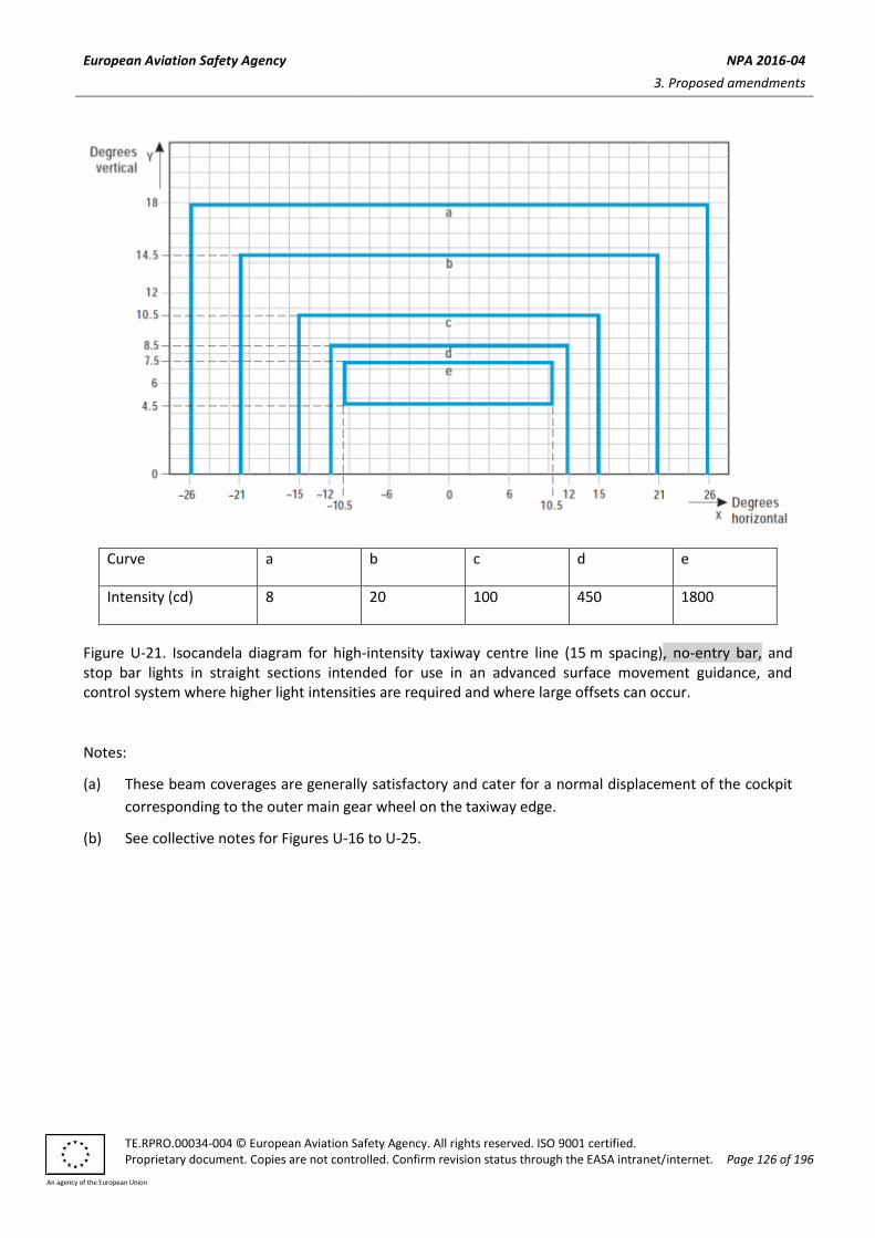
European Aviation Safety Agency NPA 2016-04
3. Proposed amendments
TE.RPRO.00034-004 © European Aviation Safety Agency. All rights reserved. ISO 9001 certified. Proprietary document. Copies are not controlled. Confirm revision status through the EASA intranet/internet. Page 126 of 196
An agency of the European Union
Curve a b c d e
Intensity (cd) 8 20 100 450 1800
Figure U-21. Isocandela diagram for high-intensity taxiway centre line (15 m spacing), no-entry bar, and stop bar lights in straight sections intended for use in an advanced surface movement guidance, and control system where higher light intensities are required and where large offsets can occur.
Notes:
(a) These beam coverages are generally satisfactory and cater for a normal displacement of the cockpit
corresponding to the outer main gear wheel on the taxiway edge.
(b) See collective notes for Figures U-16 to U-25.

European Aviation Safety Agency NPA 2016-04
3. Proposed amendments
TE.RPRO.00034-004 © European Aviation Safety Agency. All rights reserved. ISO 9001 certified. Proprietary document. Copies are not controlled. Confirm revision status through the EASA intranet/internet. Page 127 of 196
An agency of the European Union
Curve a b c d e
Intensity (cd) 8 20 100 450 1800
Figure U-22. Isocandela diagram for high-intensity taxiway centre line (15 m spacing), no-entry bar, and stop bar lights in straight sections intended for use in an advanced surface movement guidance, and control system where higher light intensities are required
Notes:
(a) These beam coverages are generally satisfactory and cater for a normal displacement of the cockpit
corresponding to the outer main gear wheel on the taxiway edge.
(b) See collective notes for Figures U-16 to U-25.

European Aviation Safety Agency NPA 2016-04
3. Proposed amendments
TE.RPRO.00034-004 © European Aviation Safety Agency. All rights reserved. ISO 9001 certified. Proprietary document. Copies are not controlled. Confirm revision status through the EASA intranet/internet. Page 128 of 196
An agency of the European Union
Curve a b c d
Intensity (cd) 8 100 200 400
Figure U-23. Isocandela diagram for high-intensity taxiway centre line (7.5 m spacing), no-entry bar, and stop bar lights in curved sections intended for use in an advanced surface movement guidance, and control system where higher light intensities are required
Notes:
(a) Lights on curves to be toed-in 17 degrees with respect to the tangent of the curve.
(b) See collective notes for Figures U-16 to U-25.
BOOK 2 – GUIDANCE MATERIAL FOR AERODROMES
Amend GM1 ADR-DSN.A.002 as follows:
GM1 ADR-DSN.A.002 Definitions
Clarification on instrument approach operations classifications based on the designed lowest operating
minima, Type A and Type B is given in ICAO Annex 6, Chapter 4.Intentionally blank

European Aviation Safety Agency NPA 2016-04
3. Proposed amendments
TE.RPRO.00034-004 © European Aviation Safety Agency. All rights reserved. ISO 9001 certified. Proprietary document. Copies are not controlled. Confirm revision status through the EASA intranet/internet. Page 129 of 196
An agency of the European Union
Amend GM1 ADR-DSN.A.005 as follows:
GM1 ADR-DSN.A.005 Aerodrome Reference Code
(...)
(c) In addition to the reference code, other aeroplane aircraft characteristics, such as aeroplane aircraft
length and tail height, may also have an impact on the design of an aerodrome. Additionally, some
characteristics of a piece of infrastructure are directly related to one element of the code (wingspan
or wheel span) but are not impacted by other. The art of the aerodrome designer should be to
consider all the relationships between aircraft characteristics and aerodromes and piece of
infrastructures characteristics.
(...)
(e) It is recognised that not all areas of the aerodrome should need to correspond to the critical
aeroplane aircraft that determines the Aerodrome Reference Code. Elements of the aerodrome
infrastructure that do not meet the requirements of the Aerodrome Reference Code for the design
aeroplane aircraft should be designated with an appropriate code letter for its dimensions.
Limitations should be identified to aircraft a/c size permitted or operating limitations. ICAO, Annex
14 does not provide sufficient flexibility for infrastructure intended for different sizes of aircraft. It
addresses only the ‘design aeroplane’ aircraft’. This enables all areas of the aerodrome to reflect the
aerodrome reference code.
(f) Further guidance is given in ICAO Doc 9157, Aerodrome Design Manual, Part 1, Runways.
Amend GM1 ADR-DSN.A.010 as follows:
GM1 ADR-DSN.A.010
iIntentionally left blank
Amend GM1 ADR-DSN.B.015 as follows:
GM1 ADR-DSN.B.015 Number, siting, and orientation of runways
(...)
(e) One important factor is the usability factor, as determined by the wind distribution which is specified
hereunder. Another important factor is the alignment of the runway to facilitate the provision of
approaches conforming to the approach surface specifications in CS1 ADR-DSN.H.425. Further
guidance on these and other factors is given Iin ICAO Annex 14, Attachment A, Section 1, information
is given concerning these and other factors. When a new instrument runway is being located,
particular attention needs to be given to areas over which aeroplanes should be required to fly when
following instrument approach and missed approach procedures so as to ensure that obstacles in
these areas or other factors should not restrict the operation of the aeroplanes for which the runway
is intended.
European Aviation Safety Agency NPA 2016-04
3. Proposed amendments
TE.RPRO.00034-004 © European Aviation Safety Agency. All rights reserved. ISO 9001 certified. Proprietary document. Copies are not controlled. Confirm revision status through the EASA intranet/internet. Page 130 of 196
An agency of the European Union
Amend GM1 ADR-DSN.B.035 as follows:
GM1 ADR-DSN.B.035 Actual Llength of the runway and declared distances
(a) Length of the runway:
(...)
(4) When performance data on aeroplanes for which the runway is intended, are not known,
guidance on the determination of the actual length of a primary runway by application of
general correction factors is given in theICAO Doc 9157, Aerodrome Design Manual, Part 1,
Runways.
(...)
Amend GM1 ADR-DSN.B.045 as follows:
GM1 ADR-DSN.B.045 Width of runways
(...)
(b) Factors affecting runway width are given in theICAO Doc 9157, Aerodrome Design Manual, Part 1,
Runways.
Amend GM1 ADR-DSN.B.055 as follows:
GM1 ADR-DSN.B.055 Minimum distance between parallel instrument runways
Guidance on procedures and facilities requirements for simultaneous operations on parallel or near-parallel instrument runways are contained in ICAO, PANS-ATM, Doc 4444, Chapter 6 and ICAO, PANS-OPS, Doc 8168, Volume I, Part III, Section 2, and Volume II, Part I, Section 3; Part II, Section 1; and Part III, Section 3, and relevant guidance is contained in ICAO Doc, 9643, Manual on Simultaneous Operations on Parallel or Near-Parallel Instrument Runways (SOIR).Intentionally blank
Amend GM1 ADR-DSN.B.070 as follows:
GM1 ADR-DSN.B.070 Sight distance for slopes of runways
Runway longitudinal slopes and slopes changes are so designed that the pilot in the aircraft has an unobstructed line of sight over all or as much of the runway as possible, thereby enabling him to see aircraft or vehicles on the runway, and to be able to manoeuvre and take avoiding action.
Amend GM1 ADR-DSN.B.080 as follows:
GM1 ADR-DSN.B.080 Transverse slopes on runways

European Aviation Safety Agency NPA 2016-04
3. Proposed amendments
TE.RPRO.00034-004 © European Aviation Safety Agency. All rights reserved. ISO 9001 certified. Proprietary document. Copies are not controlled. Confirm revision status through the EASA intranet/internet. Page 131 of 196
An agency of the European Union
iIntentionally left blank
Amend GM1 ADR-DSN.B.085 as follows:
GM1 ADR-DSN.B.085 Runway strength
(...)
(d) Overload operations
(1) Overloading of pavements can result either from loads too large, or from a substantially
increased application rate, or both. Loads larger than the defined (design or evaluation) load
shorten the design life, whilst smaller loads extend it. With the exception of massive
overloading, pavements in their structural behaviour are not subject to a particular limiting
load above which they suddenly or catastrophically fail. Behaviour is such that a pavement can
sustain a definable load for an expected number of repetitions during its design life. As a
result, occasional minor overloading is acceptable, when expedient, with only limited loss in
pavement life expectancy and relatively small acceleration of pavement deterioration. For
those operations in which magnitude of overload and/or the frequency of use do not justify a
detailed analysis, the following criteria are suggested:
(i) for flexible pavements, occasional movements by aircraft with ACN not exceeding 10 %
above the reported PCN should not adversely affect the pavement;
(ii) for rigid or composite pavements in which a rigid pavement layer provides a primary
element of the structure, occasional movements by aircraft with ACN not exceeding 5 %
above the reported PCN should not adversely affect the pavement, and
(iii) if the pavement structure is unknown, the 5 % limitation should apply; and
(iv) the annual number of overload movements should not exceed approximately 5 % of the
total annual aircraft movements.
(e) Such overload movements should not normally be permitted on pavements exhibiting signs of
distress or failure. Furthermore, overloading should be avoided during any periods of thaw following
frost penetration, or when the strength of the pavement or its subgrade could be weakened by
water. Where overload operations are conducted, the relevant pavement condition should be
reviewed regularly. Also the criteria for overload operations should be reviewed periodically since
excessive repetition of overloads can cause severe shortening of pavement life or require major
rehabilitation of pavement. Further information is contained in the ICAO Doc 9157, Aerodrome
Design Manual, Part 3, Pavements.
Amend GM1 ADR-DSN.B.090 as follows:
GM1 ADR-DSN.B.090 Surface of runways

European Aviation Safety Agency NPA 2016-04
3. Proposed amendments
TE.RPRO.00034-004 © European Aviation Safety Agency. All rights reserved. ISO 9001 certified. Proprietary document. Copies are not controlled. Confirm revision status through the EASA intranet/internet. Page 132 of 196
An agency of the European Union
(a) In adopting tolerances for runway surface irregularities, the following standard of construction is
achievable for short distances of 3 m and conform to a good engineering practice is that: except
across the crown of a camber or across drainage channels, the finished surface of the wearing course
is to be of such regularity that when tested with a 3 m straight-edge placed anywhere in any
direction on the surface, there is no deviation greater than 3 mm between the bottom of the
straight-edge and the surface of the pavement anywhere along the straight-edge.
(...)
(c) Additional guidance on surface of runways is given in ICAO Doc 9157, Aerodrome Design Manual, Part 3, Pavements.
(d) Macrotexture and microtexture should be taken into consideration in order to provide the required surface friction characteristics. Additional guidance is given in GM1 ADR-DSN.B.191. Additional guidance on design and methods for improving runway surface texture is given in ICAO Doc 9157, Aerodrome Design Manual, Part 3, Pavements.
Delete SECTION 1 as follows:
SECTION 1 — RUNWAY TURN PADS
Amend GM1 ADR-DSN.B.095 as follows:
GM1 ADR-DSN.B.095 Runway turn pads
(...)
Figure GM-B-3. Typical turn pad layout
Amend GM1 ADR-DSN.B.105 as follows:
GM1 ADR-DSN.B.105 Strength of runway turn pads
European Aviation Safety Agency NPA 2016-04
3. Proposed amendments
TE.RPRO.00034-004 © European Aviation Safety Agency. All rights reserved. ISO 9001 certified. Proprietary document. Copies are not controlled. Confirm revision status through the EASA intranet/internet. Page 133 of 196
An agency of the European Union
iIntentionally left blank
Amend GM1 ADR-DSN.B.110 as follows:
GM1 ADR-DSN.B.110 Surface of runway turn pads
iIntentionally left blank
Amend GM1 ADR-DSN.B.120 as follows:
GM1 ADR-DSN.B.120 Strength of shoulders for runway turn pads
iIntentionally left blank
Delete SECTION 2 as follows:
SECTION 2 — RUNWAY SHOULDERS
Amend GM1 ADR-DSN.B.125 as follows:
GM1 ADR-DSN.B.125 Runway shoulders
(...)
(c) However, for runways where the code letter is D, there may be circumstances where the shoulder need not be paved. Where the runway is not used by 4-engined aircraft, it may be possible to contain the risk from erosion or the ingestion of debris in the absence of paved shoulders. In such cases:
(a) The ground should be prepared so that there is full grass coverage with no loose gravel or other material. This may include additional materials if the bearing strength and surface of the ground are not sufficient.
(b) A programme of inspections of the shoulders and runway may be implemented to confirm its continuing serviceability, and ensure that there is no deterioration that could create a risk of foreign object debris (FOD), or otherwise hazard aircraft operations.
(...)
The runway shoulder width may be reduced if the width of the runway and the configuration of the aircraft so permit, and confirmed by safety assessment. Further guidance is given in ICAO Doc 9157, Aerodrome Design Manual, Part 1, Runways).
Amend GM1 ADR-DSN.B.130 as follows:

European Aviation Safety Agency NPA 2016-04
3. Proposed amendments
TE.RPRO.00034-004 © European Aviation Safety Agency. All rights reserved. ISO 9001 certified. Proprietary document. Copies are not controlled. Confirm revision status through the EASA intranet/internet. Page 134 of 196
An agency of the European Union
GM1 ADR-DSN.B.130 Slopes on runway shoulders
iIntentionally left blank
Amend GM1 ADR-DSN.B.135 as follows:
GM1 ADR-DSN.B.135 Width of runway shoulders
iIntentionally left blank
Amend GM1 ADR-DSN.B.140 as follows:
GM1 ADR-DSN.B.140 Strength of runway shoulders
Additional Gguidance on strength of runway shoulders is given in the ICAO, Doc 9157, Aerodrome Design Manual Part 1, Runways.
(b) Additional guidance on strength of runway shoulders is given in ICAO Doc 9157, Aerodrome Design Manual, Part 1, Runways.
Delete SECTION 3 as follows:
SECTION 3 — RUNWAY STRIP
Amend GM1 ADR-DSN.B.150 as follows:
GM1 ADR-DSN.B.150 Runway strip to be provided
iIntentionally left blank
Amend GM1 ADR-DSN.B.155 as follows:
GM1 ADR-DSN.B.155 Length of runway strip
iIntentionally left blank
Amend GM1 ADR-DSN.B.160 as follows:
GM1 ADR-DSN.B.160 Width of runway strip
iIntentionally left blank

European Aviation Safety Agency NPA 2016-04
3. Proposed amendments
TE.RPRO.00034-004 © European Aviation Safety Agency. All rights reserved. ISO 9001 certified. Proprietary document. Copies are not controlled. Confirm revision status through the EASA intranet/internet. Page 135 of 196
An agency of the European Union
Amend GM1 ADR-DSN.B.165 as follows:
GM1 ADR-DSN.B.165 Objects on runway strips
Within the graded general area of the runway strip adjacent to the runway, measures should be taken to prevent an aeroplane’s wheel when sinking into the ground, from striking a hard vertical face. Special problems may arise for runway light fittings or other objects mounted in the strip or at the intersection with a taxiway or another runway. In the case of constructions within the graded area of the runway strip, such as intersecting runways or taxiways, where the surface should also be flush with the strip surface, they should be delethalised, that is, so constructed as to avoid presenting a buried vertical face to aircraft wheels in soft ground conditions in any direction from which an aircraft is likely to approach. Aa vertical face can be eliminated by chamfering from the top of those constructions to not less than 30 cm below the strip surface level. Other objects situated within the graded portion of the runway strip, the functions of which do not require them to be at surface level, should be buried to a depth of not less than 30 cm. Where this is not feasible, to eliminate a buried vertical surface, a slope should be provided which extends from the top of the construction to not less than 30 cm below ground level. The slope can be created by using a mixture of compacted gravel or asphalt or crushed aggregates and soil. The slope should be no greater than 1:10.
Amend GM1 ADR-DSN.B.170 as follows:
GM1 ADR-DSN.B.170
iIntentionally left blank
Amend GM1 ADR-DSN.B.175 as follows:
GM1 ADR-DSN.B.175 Grading of runway strips
(a) For a precision approach runway, where the code number is 3 or 4, it may be desirable to adopt a greater width of that portion of a strip to be graded should be considered. where the code number is 3 or 4. Figure GM-B-4 shows the shape and dimensions of a wider strip that may be considered for such a runway. This strip has been designed using information on aircraft running off runways. The portion to be graded extends to a distance of 105 m from the centre line, except that the distance is gradually reduced to 75 m from the centre line at both ends of the strip, for a length of 150 m from the runway end.

European Aviation Safety Agency NPA 2016-04
3. Proposed amendments
TE.RPRO.00034-004 © European Aviation Safety Agency. All rights reserved. ISO 9001 certified. Proprietary document. Copies are not controlled. Confirm revision status through the EASA intranet/internet. Page 136 of 196
An agency of the European Union
Figure GM-B-4. Graded portion of a strip including a precision approach runway where the code number is 3 or 4
(b) Where the areas in paragraph (a) above have paved surface, they should be able to withstand the occasional passage of the critical aeroplane for runway pavement design.
(c) The area adjacent to the end of a runway may be referred to as a blast pad.
Amend GM1 ADR-DSN.B.180 as follows:
GM1 ADR-DSN.B.180 Longitudinal Slopes on runway strips
iIntentionally left blank
Amend GM1 ADR-DSN.B.185 as follows:
GM1 ADR-DSN.B.185 Transverse slopes on runway strips
iIntentionally left blank
Amend GM1 ADR-DSN.B.190 as follows:
GM1 ADR-DSN.B.190 Strength of runway strips
Since the graded portion of a strip is provided to minimise the hazard to an aircraft running off the runway, it should be graded grant sufficient strength in such a manner as to prevent the collapse of the landing nose gear of the aircraft. The surface should be prepared in such a manner as to provide drag to an aircraft and below the surface, it should have sufficient bearing strength to avoid damage to the aircraft. To meet these divergent needs, the following guidelines are provided for preparing the strip. It is noted, that a depth of 15 cm is a depth to which the nose gear may sink without collapsing. Therefore, it is recommended that the soil at a depth of 15 cm below the finished strip surface should be prepared to have a sufficient stability, demonstrated by bearing strength of California Bearing Ratio (CBR) value of 15 to 20. The intention of this is to prevent the nose gear from damage. The top 15 cm may be of lesser strength which would facilitate deceleration of aircraft. There are also other methods technical systems for soil investigation. In case of a deeper sinking than 15 cm, the maximum wheel sinking without collapsing should be examined by using

European Aviation Safety Agency NPA 2016-04
3. Proposed amendments
TE.RPRO.00034-004 © European Aviation Safety Agency. All rights reserved. ISO 9001 certified. Proprietary document. Copies are not controlled. Confirm revision status through the EASA intranet/internet. Page 137 of 196
An agency of the European Union
different technical systems methods of soil investigation. The intention of this is to prevent the nose gear from damage. The top 15 cm may be of lesser strength which would facilitate deceleration of aircraft.
Insert new GM1 ADR-DSN.B.191 as follows:
GM1 ADR-DSN.B.191 Drainage characteristics of the movement area and adjacent areas
(a) Rapid drainage of surface water is a primary safety consideration in the design, construction and
maintenance of movement area and adjacent areas.
(b) There are two distinct drainage processes:
(1) natural drainage of the surface water from the top of the pavement surface until it reaches the
final recipient such as rivers or other water bodies; and
(2) dynamic drainage of the surface water trapped under a moving tire until it reaches outside the
tire-to-ground contact area.
Both drainage processes can be controlled through design, construction and maintenance of the
pavements in order to prevent accumulation of water on the pavement surface.
(c) Surface drainage is a basic requirement and serves to minimise water depth on the surface.
Adequate surface drainage is provided primarily by an appropriately sloped surface (in both the
longitudinal and transverse directions). The resulting combined longitudinal and transverse slope is
the path for the drainage runoff. This path can be shortened by adding transverse grooves.
(d) Dynamic drainage is achieved through built-in texture in the pavement surface. The rolling tire builds
up water pressure and squeezes the water out the escape channels provided by the texture. The
dynamic drainage of the tire-to-ground contact area may be improved by adding transverse grooves
provided that they are subject to rigorous maintenance.
(e) Through construction, the drainage characteristics of the surface are built into the pavement. These
surface characteristics are:
(1) Slopes;
(2) Texture:
(i) Microtexture;
(ii) Macrotexture.
(f) Slopes for the various parts of the movement area and adjacent parts are described in Chapters B to
G and figures are given as per cent. Further guidance is given in ICAO Doc 9157, Aerodrome Design
Manual, Part 1, Runways, Chapter 5.
(g) Texture in the literature is described as microtexture or macrotexture. These terms are understood
differently in various part of the aviation industry.
(h) Microtexture is the texture of the individual stones and is hardly detectable by the eye. Microtexture
is considered a primary component in skid resistance at slow speeds. On a wet surface at higher
speeds a water film may prevent direct contact between the surface asperities and the tire due to

European Aviation Safety Agency NPA 2016-04
3. Proposed amendments
TE.RPRO.00034-004 © European Aviation Safety Agency. All rights reserved. ISO 9001 certified. Proprietary document. Copies are not controlled. Confirm revision status through the EASA intranet/internet. Page 138 of 196
An agency of the European Union
insufficient drainage from the tire-to-ground contact area. Microtexture is a built-in quality of the
pavement surface. By specifying crushed material that will withstand polishing microtexture,
drainage of thin water films are ensured for a longer period of time. Resistance against polishing is
expressed in terms of the polished stone values (PSV) which is in principle a value obtained from a
friction measurement in accordance with international standards. These standards define the PSV
minima that will enable a material with a good microtexture to be selected. A major problem with
microtexture is that it can change within short time periods without being easily detected. A typical
example of this is the accumulation of rubber deposits in the touchdown area which will largely mask
microtexture without necessarily reducing macrotexture.
(k) Macrotexture is the texture among the individual stones. This scale of texture may be judged
approximately by the eye. Macrotexture is primarily created by the size of aggregate used or by
surface treatment of the pavement and is the major factor influencing drainage capacity at high
speeds. Materials shall be selected so as to achieve good macrotexture.
(l) The primary purpose of grooving a runway surface is to enhance surface drainage. Natural drainage
can be slowed down by surface texture, but grooving can speed up the drainage by providing a
shorter drainage path and increasing the drainage rate.
(m) For measurement of macrotexture, simple methods such as the ‘sand and grease patch’ methods
described in ICAO Doc 9137, Airport Services Manual, Part 2, Pavement Surface Conditions were
developed. These methods were used for the early research on which current airworthiness
requirements are based and which refer to a classification categorising macrotexture from A to E.
This classification was developed, using sand or grease patch measuring techniques, and issued in
1971 by the Engineering Sciences Data Unit (ESDU).
Runway classification based on texture information from ESDU 71026:
Classification Texture depths (mm)
A 0.10 – 0.14
B 0.15 – 0.24
C 0.25 – 0.50
D 0.51 – 1.00
E 1.01 – 2.54
(n) Using this classification, the threshold value between microtexture and macrotexture is 0.1 mm
mean texture depth (MTD). Related to this scale, the normal wet runway aircraft performance is
based upon texture giving drainage and friction qualities midway between classification B and C
(0.25 mm). Improved drainage through better texture might qualify for a better aircraft performance
class. However, such credit must be in accordance with aeroplane manufacturers’ documentation.
Presently credit is given to grooved or porous friction course runways following design, construction
and maintenance criteria. The harmonised certification standards of some States refer to texture
giving drainage and friction qualities midway between classification D and E (1.0 mm).
European Aviation Safety Agency NPA 2016-04
3. Proposed amendments
TE.RPRO.00034-004 © European Aviation Safety Agency. All rights reserved. ISO 9001 certified. Proprietary document. Copies are not controlled. Confirm revision status through the EASA intranet/internet. Page 139 of 196
An agency of the European Union
(o) For construction, design and maintenance, various international standards are used. Currently ISO 13473-1: ‘Characterization of pavement texture by use of surface profiles — Part 1: Determination of Mean Profile Depth’ links the volumetric measuring technique with non-contact profile measuring techniques giving comparable texture values. These standards describe the threshold value between microtexture and macrotexture as 0.5 mm. The volumetric method has a validity range from 0.25 to 5 mm MTD. The profilometry method has a validity range from 0 to 5 mm mean profile depth (MPD). The values of MPD and MTD differ due to the finite size of the glass spheres used in the volumetric technique and because the MPD is derived from a two-dimensional profile rather than a three-dimensional surface. Therefore, a transformation equation must be established for the measuring equipment used to relate MPD to MTD.
(p) The ESDU scale groups runway surfaces based on macrotexture from A through E, where E represents the surface with best dynamic drainage capacity. The ESDU scale thus reflects the dynamic drainage characteristics of the pavement. Grooving any of these surfaces enhances the dynamic drainage capacity. The resulting drainage capacity of the surface is thus a function of the texture (A through E) and grooving. The contribution from grooving is a function of the size of the grooves and the spacing between the grooves. Aerodromes exposed to heavy or torrential rainfall must ensure that the pavement and adjacent areas have drainage capability to withstand these rainfalls or put limitations on the use of the pavements under such extreme situations. These airports should seek to have the maximum allowable slopes and the use of aggregates providing good drainage characteristics. They should also consider grooved pavements in the E classification to ensure that safety is not impaired.
Delete SECTION 4 as follows:
SECTION 4 — CLEARWAYS, STOPWAYS AND RADIO ALTIMETER OPERATING AREA
Amend GM1 ADR-DSN.B.200 as follows:
GM1 ADR-DSN.B.200 Stopways
(...)
(c) The economy of a stopway can be entirely lost if, after each usage, it should be regraded and compacted. Therefore, it should be designed to withstand at least a certain number of loadings of the aeroplane which the stopway is intended to serve without inducing structural damage to the aeroplane. Notwithstanding that a stopway may have a paved surface, it is not intended that PCN Figures need to be developed for a stopway. Further guidance is given may be found in ICAO Doc 4444, PANS-OPS.
Amend GM1 ADR-DSN.B.205 as follows:
GM1 ADR-DSN.B.205 Radio altimeter operating area
(...)
European Aviation Safety Agency NPA 2016-04
3. Proposed amendments
TE.RPRO.00034-004 © European Aviation Safety Agency. All rights reserved. ISO 9001 certified. Proprietary document. Copies are not controlled. Confirm revision status through the EASA intranet/internet. Page 140 of 196
An agency of the European Union
(b) The inclusion of detailed specifications for radio altimeter operating area in this GM is not intended to imply that a radio altimeter operating area has to be provided.
(b)(c) With a radio altimeter operating area in the pre-threshold area of a precision approach runway the margin to calculate the decision altitude should be smaller and the usability of the adjacent runway may be enhanced.
(c)(d) Further guidance on radio altimeter operating area is given in ICAO Doc 9365, Manual of All-Weather Operations, (ICAO, Doc 9365, Section 5.2). Guidance on the use of radio altimeter is given in the ICAO, PANS-OPS, Volume II, Part II, Section 1.
Delete CHAPTER C as follows:
CHAPTER C — RUNWAY END SAFETY AREA
Amend GM1 ADR-DSN.C.210 as follows:
GM1 ADR-DSN.BC.210 Runway end safety areas (RESA)
(a) General
(1) A runway end safety area should provide an area long and wide enough, and suitable to contain overruns and undershoots resulting from a reasonably probable combination of adverse operational factors. On a precision approach runway, the ILS localiser is normally the first upstanding obstacle, and the runway end safety area should extend up to this facility. In other circumstances and on a non-precision approach runway, the first upstanding obstacle may be a road, a railroad, or other constructed or natural feature. In such circumstances, tThe provisions of a runway end safety area should extend as far as the obstacle take such obstacle into consideration.
(...)
(b) Assessment of runway end safety areas
(...)
(2) Combined with this, measures may be considered that would reduce the severity of the consequences should an event occur. Wherever practicable, aerodrome operators should seek to optimise the RESA. This may be achieved through a combination of:
(...)
(iii) reducing runway declared distances in order to provide the necessary RESA may be a viable option where the existing runway length exceeds that required for the existing or projected design aircraft. If the take-off distance required for the critical aircraft operating at the aerodrome is less than the take-off distance available, there may be an opportunity to reduce the relevant runway declared distances. Where provision of a runway end safety area would be particularly prohibitive to implement consideration would have to be given to reducing some of the declared distances of the runway for the provision of a runway end safety area and installation of an arresting system;
(...)
(...)

European Aviation Safety Agency NPA 2016-04
3. Proposed amendments
TE.RPRO.00034-004 © European Aviation Safety Agency. All rights reserved. ISO 9001 certified. Proprietary document. Copies are not controlled. Confirm revision status through the EASA intranet/internet. Page 141 of 196
An agency of the European Union
(c) Arresting systems on runway end safety areas
(1) In recent years, recognising the difficulties associated with achieving a standard runway end safety area (RESA) at all aerodromes, research programmes have been undertaken on the use of various materials for arresting systems. Furthermore, research programmes have been undertaken to evaluate and develop arrestor systems using engineered materials (EMAS). This research was driven by the recognition that many runways where natural obstacles, local development, and/or environmental constraints inhibit the provision of RESA (as required by changes to ICAO SARPS in 1999) lead to limited dimension RESAs. Additionally, there had been accidents at some aerodromes where the ability to stop an overrunning aeroplane within the RESA would have prevented major damage to aeroplane and/or injuries to passengers.
(2) The research programmes, as well as evaluation of actual aeroplane overruns into arresting system, an EMAS installation, have demonstrated that the performance of some arresting EMAS systems can be predictable and are effective in arresting aeroplane overruns.
(3) EMAS or other aArresting system designs should be supported by a validated design method that can predict the performance of the system. The design method should be derived from field or laboratory tests. Testing may be based either on passage of an actual aircraft or an equivalent single wheel load through a test bed. The design should consider multiple aircraft parameters, including but not limited to allowable aircraft gear loads, gear configuration, tire contact pressure, aircraft centre of gravity, and aircraft speed. The model should calculate imposed aircraft gear loads, g-forces on aircraft occupants, deceleration rates, and stopping distances within the arresting system. Any rebound of the crushed material that may lessen its effectiveness, should also be considered.
(4) Demonstrated performance of an arresting system can be achieved by a validated design method which can predict the performance of the system. The design and performance should be based on the type of aeroplane aircraft anticipated to use the associated runway that imposes the greatest demand upon the arresting system. The system design of an arresting system should be based on a critical (or design) aircraft which is defined as aircraft using the associated runway that imposes the greatest demand upon the arresting system. This is usually but not always, the heaviest/largest aircraft that regularly uses the runway. Arresting system performance is dependent not only on aircraft weight but allowable aeroplane landing gear loads, gear configuration,and tire contact pressure, aeroplane centre of gravity and aeroplane speed. Accommodating undershoots should also be addressed. All configurations should be considered in optimising the arresting system design. The aerodrome operator and arresting system manufacturer should consult regarding the selection of the design aeroplane aircraft that should optimise the arresting system for a particular aerodrome. Additionally, the design should allow the safe operation of fully loaded rescue and fire fighting vehicles, including their ingress and egress.
(5) EASA considers that the FAA performance specifications and requirements which have been accepted by the ICAO Aerodromes Panel, provide suitable information for aerodromes considering the installation of arresting systemEMAS. Therefore, attention is drawn to the documents listed below which give guidance on the requirements and evaluation process used by the FAA:
(i) FAA Advisory Circular 150/5300-13 — ‘Airport Design’;
(ii) FAA Advisory Circular 150/5220-22BA — ‘Engineered Materials Arresting Systems(EMAS)
for Aeroplane Overruns’;
(iii) FAA Order 5200.8 — ‘Runway Safety Area Program’;

European Aviation Safety Agency NPA 2016-04
3. Proposed amendments
TE.RPRO.00034-004 © European Aviation Safety Agency. All rights reserved. ISO 9001 certified. Proprietary document. Copies are not controlled. Confirm revision status through the EASA intranet/internet. Page 142 of 196
An agency of the European Union
(iv) FAA Order 5200.9 — ‘EMAS Financial Feasibility and Equivalency’.
(6) The presence of an arresting system should be published in the AIP entry and information/instructions promulgated to local runway safety teams and others to promote awareness in the pilot community.
(5)(7) Additional information is given in the ICAO Doc 9157, Aerodrome Design Manual, Part 1, Runways.
Figure GM-C-1. Runway end safety area for a runway where the code number is 3 or 4
Amend GM1 ADR-DSN.C.215 as follows:
GM1 ADR-DSN.CB.215 Dimensions of runway end safety areas
(...)
Amend GM1 ADR-DSN.C.220 as follows:
GM1 ADR-DSN.CB.220 Objects on runway end safety areas
(...)
Amend GM1 ADR-DSN.C.225 as follows:
GM1 ADR-DSN.CB.225 Clearing and grading of runway end safety areas

European Aviation Safety Agency NPA 2016-04
3. Proposed amendments
TE.RPRO.00034-004 © European Aviation Safety Agency. All rights reserved. ISO 9001 certified. Proprietary document. Copies are not controlled. Confirm revision status through the EASA intranet/internet. Page 143 of 196
An agency of the European Union
(...)
(b) Guidance on Cclearing and grading of runway end safety areas is given in the ICAO Doc 9157, Aerodrome Design Manual, Part 1, Runways).
Amend GM1 ADR-DSN.C.230 as follows:
GM1 ADR-DSN.CB.230 Slopes on runway end safety areas
(...)
Amend GM1 ADR-DSN.C.235 as follows:
GM1 ADR-DSN.CB.235 Strength of runway end safety areas
(...)
(b) Guidance on the strength of a runway end safety area is given in the GM1 ADR-DSN.B.190 Strength
of runway strips and in ICAO Doc 9157, Aerodrome Design Manual, Part 1, Runways).
Insert new CHAPTER C as follows:
CHAPTER C — RUNWAY STARTER EXTENSION
Insert new GM1 ADR-DSN.C.236 as follows:
GM1 ADR-DSN.C.236 Runway starter extension physical characteristics
(a) A runway starter extension gives an extra distance for take-offs, however, is not considered to be a part of the runway. It means that declared distances of the runway remain unaffected by installation of the runway starter extension. In certain cases, it may be needed to reconsider Obstacle Limitation Surfaces (OLS) and procedures for air navigation services – aircraft operations. (PANS-OPS) surfaces to correspond with requirements for higher aerodrome reference code.
(b) It may be necessary to provide runway extra width at the end of the runway starter extension to enable aeroplanes to turn around. Such extra width provided should comply with applicable requirements for runway turn pads.
Insert new GM1 ADR-DSN.C.237 as follows:
GM1 ADR-DSN.C.237 Runway starter extension shoulders
intentionally left blank

European Aviation Safety Agency NPA 2016-04
3. Proposed amendments
TE.RPRO.00034-004 © European Aviation Safety Agency. All rights reserved. ISO 9001 certified. Proprietary document. Copies are not controlled. Confirm revision status through the EASA intranet/internet. Page 144 of 196
An agency of the European Union
Insert new GM1 ADR-DSN.C.238 as follows:
GM1 ADR-DSN.C.238 Runway starter extension strip
The length of the runway starter extension strip may need to be increased for other factors, e.g. blast (see Figure C-1).
Amend GM1 ADR-DSN.D.240 as follows:
GM1 ADR-DSN.D.240 Taxiways general
(...) (e) A perimeter taxiway is ideally designed according to the following criteria:
(1) Sufficient space is required between the landing threshold and the taxiway centre line where it
crosses under the approach path, to enable the critical aeroplane aircraft to pass under the
approach without violating the approach surface.
(...)
(...)
(g) The runway/taxiway configuration should be ‘regular’, for example with single taxiway entrances;
this is especially important for taxiways across runways. Examples of good configuration include:
(h) The main design principles for entry and exit taxiways are :
(1) Taxiways should be perpendicular to the runway centre line if possible.
(...)
(i) Aerodrome infrastructure can also be used to support design, whether by the systems installed or by
their operating characteristics. Examples include:
(...)
(1) Avoid confusion between CAT I Cat 1 and CAT III Cat 3 holding positions. This may be achieved
in some circumstances by combining both holding positions.
(j) Guidance on layout of taxiways is given in the ICAO Doc 9157, Aerodrome Design Manual, Part 2, Taxiways, Aprons and Holding Bays).
Amend GM1 ADR-DSN.D.250 as follows:
GM1 ADR-DSN.D.250 Taxiways curves
(...)
(c) An example of widening taxiways to achieve the wheel clearance specified is illustrated in Figure GM-
D-1. Guidance on the values of suitable dimensions is given in the ICAO Doc 9157, Aerodrome Design
Manual, Part 2, Taxiways, Aprons and Holding Bays).

European Aviation Safety Agency NPA 2016-04
3. Proposed amendments
TE.RPRO.00034-004 © European Aviation Safety Agency. All rights reserved. ISO 9001 certified. Proprietary document. Copies are not controlled. Confirm revision status through the EASA intranet/internet. Page 145 of 196
An agency of the European Union
Figure GM-D-1. Taxiway curve
Amend GM1 ADR-DSN.D.255 as follows:
GM1 ADR-DSN.D.255 Junction and intersection of taxiways
Consideration should be given to the aeroplane datum length when designing fillets. Guidance on the design of fillets and the definition of the term aeroplane datum length are given in the ICAO Doc 9157, Aerodrome Design Manual, Part 2, Taxiways, Aprons and Holding Bays).
Amend GM1 ADR-DSN.D.260 as follows:
GM1 ADR-DSN.D.260 Taxiway minimum separation distance
(a) Guidance on factors which may be considered in the safety assessment is given in the ICAO Doc
9157, Aerodrome Design Manual, Part 2, Taxiways, Aprons and Holding Bays.
(...)
Taxiway width, (see CS D.245(a))
Location of taxiway centre line lights and markings (see CS M.710(d)(1) and L.555(b)(1), (b)(2))
The Figure shows an example of taxiway widening to achieve the specified wheel clearance on taxiway curves (see CS D.240(a)).
Minimum wheel clearance (see CS D.240(a))

European Aviation Safety Agency NPA 2016-04
3. Proposed amendments
TE.RPRO.00034-004 © European Aviation Safety Agency. All rights reserved. ISO 9001 certified. Proprietary document. Copies are not controlled. Confirm revision status through the EASA intranet/internet. Page 146 of 196
An agency of the European Union
(c) The separation distances, as prescribed in Table D-1, column (10), do not necessarily provide the
capability of making a normal turn from one taxiway to another parallel taxiway. Guidance for this
condition is given in the ICAO Doc 9157, Aerodrome Design Manual, Part 2, Taxiways, Aprons and
Holding Bays.
Amend GM1 ADR-DSN.D.265 as follows:
GM1 ADR-DSN.D.265 Longitudinal slopes on taxiways
iIntentionally left blank
Amend GM1 ADR-DSN.D.270 as follows:
GM1 ADR-DSN.D.270 Longitudinal slope changes on taxiways
iIntentionally left blank
Amend GM1 ADR-DSN.D.275 as follows:
GM1 ADR-DSN.D.275 Sight distance of taxiways
iIntentionally left blank
Amend GM1 ADR-DSN.D.285 as follows:
GM1 ADR-DSN.D.285 Strength of taxiways
Information regarding pavement bearing strength, including the ACN/PCN classification system may be found in GM1 -ADR-DSN.B.085.
Due consideration being given to the fact that a taxiway should be subjected to a greater density of traffic and as a result of slow moving and stationary aeroplanes, to higher stresses than the runway it serves.
Amend GM1 ADR-DSN.D.290 as follows:
GM1 ADR-DSN.D.290 Surface of taxiways
Suitable surface friction characteristics are those surface properties required on taxiways that assure safe operation of aeroplanes. Intentionally blank
Amend GM1 ADR-DSN.D.295 as follows:

European Aviation Safety Agency NPA 2016-04
3. Proposed amendments
TE.RPRO.00034-004 © European Aviation Safety Agency. All rights reserved. ISO 9001 certified. Proprietary document. Copies are not controlled. Confirm revision status through the EASA intranet/internet. Page 147 of 196
An agency of the European Union
GM1 ADR-DSN.D.295 Rapid exit taxiways
(a) The following guidance applies particularly to rapid exit taxiways (sSee Figure D-1). The general
requirements for taxiways, as prescribed in Book 1 are also applicable to rapid exit taxiways.
Guidance on the provision, location and design of rapid exit taxiways is included in the ICAO Doc
9157, Aerodrome Design Manual, Part 2, Taxiways, Aprons and Holding Bays).
(b) The locations of rapid exit taxiways along a runway are based on several criteria described in the
ICAO Doc 9157, Aerodrome Design Manual, Part 2, Taxiways, Aprons and Holding Bays), in addition
to different speed criteria.
Amend GM1 ADR-DSN.D.305 as follows:
GM1 ADR-DSN.D.305 Taxiway shoulders
Guidance on characteristics of taxiway shoulders and on shoulder treatment is given in the ICAO Doc 9157, Aerodrome Design Manual, Part 2, Taxiways, Aprons and Holding Bays).
Amend GM1 ADR-DSN.D.310 as follows:
GM1 ADR-DSN.D.310 Taxiway Strip
A taxiway strip should be so prepared or constructed as to minimise hazards arising from differences in load bearing capacity to aeroplanes which the taxiway is intended to serve in the event of an aeroplane accidentally running off the taxiway.
Guidance on characteristics of taxiway strips is given in the ICAO Doc 9157, Aerodrome Design Manual, Part 2, Taxiways, Aprons and Holding Bays).
Amend GM1 ADR-DSN.D.315 as follows:
GM1 ADR-DSN.D.315 Width of taxiway strips
iItentionally left blank
Amend GM1 ADR-DSN.D.325 as follows:
GM1 ADR-DSN.D.325 Grading of taxiway strips
iIntentionally left blank

European Aviation Safety Agency NPA 2016-04
3. Proposed amendments
TE.RPRO.00034-004 © European Aviation Safety Agency. All rights reserved. ISO 9001 certified. Proprietary document. Copies are not controlled. Confirm revision status through the EASA intranet/internet. Page 148 of 196
An agency of the European Union
Amend GM1 ADR-DSN.D.330 as follows:
GM1 ADR-DSN.D.330 Slopes on taxiway strips
iIntentionally left blank
Amend GM1 ADR-DSN.D.335 as follows:
GM1 ADR-DSN.D.335 Holding bays, runway-holding positions, intermediate holding positions,
and road-holding positions
(...)
(e) Further guidance is given in ICAO Doc 9157, Aerodrome Design Manual, Part 2, Taxiways, Aprons and Holding Bays) and ICAO Doc 4444, Procedures for Air Navigation Services — Air Traffic Management (ICAO, Doc 4444).
Amend GM1 ADR-DSN.D.340 as follows:
GM1 ADR-DSN.D.340 Location of holding bays, runway-holding positions, intermediate holding
positions, and road-holding positions
(...)
(c) An aircraft taxiing could endanger aircraft operations when the aircraft is too close to the runway during take-off and landings. It is so advised to check if the aircraft taking off or landing could be hinder. For this OLS and specially approach surfaces, take-off climb surfaces and OFZ are the first aspects to consider. An aircraft taxiing could also endanger aircraft operations when the aircraft location and orientation are so that the aircraft interfere with navigation aids. It is specific to instrument runways and especially important for precision approach runways. The non-penetration of critical/sensitive areas is the first check. The areas within which this degradable interference of course or path signals are possible need to be defined and recognised. For the purposes of developing protective zoning criteria for ILS, these areas are critical areas and sensitive areas. The ILS critical area is an area of defined dimensions about the localizer and glide path antennas where vehicles, including aircraft, are excluded during all ILS operations. The critical area is protected because the presence of vehicles and/or aircraft inside its boundaries will cause unacceptable disturbance to the ILS signal-in-space. The ILS sensitive area is an area extending beyond the critical area where the parking and/or movement of vehicles, including aircraft, is controlled to prevent the possibility of unacceptable interference to the ILS signal during ILS operations.
(...)
(e) If the affected runway is used under precision approach procedures, it should be also verified that the distance between a holding bay, runway-holding position established at a taxiway/runway intersection or road-holding position and the centre line of a runway is so that a holding aircraft or vehicle should not infringe the obstacle-free zone and the critical/sensitive areas of precision approach navigation aids (e.g. ILS/MLS).

European Aviation Safety Agency NPA 2016-04
3. Proposed amendments
TE.RPRO.00034-004 © European Aviation Safety Agency. All rights reserved. ISO 9001 certified. Proprietary document. Copies are not controlled. Confirm revision status through the EASA intranet/internet. Page 149 of 196
An agency of the European Union
(...)
(h) In radiotelephony phraseologies, the expression ‘holding point’ is used to designate the runway-holding position.
(i) Further guidance is given in ICAO Doc 9157, Aerodrome Design Manual, Part 2, Taxiways, Aprons and Holding Bays).
Amend GM1 ADR-DSN.E.345 as follows:
GM1 ADR-DSN.E.345 General
iIntentionally left blank
Amend GM1 ADR-DSN.E.350 as follows:
GM1 ADR-DSN.E.350 Size of aprons
(...)
(b) The amount of area required for a particular apron layout depends upon the following factors:
(1) the size and manoeuvrability characteristics of the aircraft using the apron;
(2) the volume of traffic using the apron;
(3) clearance requirements;
(4) type of ingress and egress to the aircraft stand;
(5) basic terminal layout or other aerodrome use;
(6) aircraft ground activity requirements; and
(7) taxiways and apron service roads.
(c) Passenger aircraft services that are carried out during the time the aircraft is parked in a stand position include: galley; toilet and potable water service; baggage handling; fuelling; provision of air conditioning, oxygen, electrical power supply and starting air; and aircraft towing. Most of these functions have a vehicle and/or equipment associated with them, or have some type of fixed installation established to conduct these services. Further guidance is given in (ICAO Doc 9157, Aerodrome Design Manual, Part 2, Taxiways, Aprons and Holding Bays, par. 3.4.6).
(d) Consideration should be given to providing sufficient area on the starboard side of the aircraft to support the level of activity that take place in the turnaround operation. Further guidance is given in (ICAO Doc 9157, Aerodrome Design Manual, Part 2, Taxiways, Aprons and Holding Bays, par. 3.4.6).
Amend GM1 ADR-DSN.E.360 as follows:
GM1 ADR-DSN.E.360 Slopes on aprons
(...)

European Aviation Safety Agency NPA 2016-04
3. Proposed amendments
TE.RPRO.00034-004 © European Aviation Safety Agency. All rights reserved. ISO 9001 certified. Proprietary document. Copies are not controlled. Confirm revision status through the EASA intranet/internet. Page 150 of 196
An agency of the European Union
(b) Slopes on apron have the same purpose as other pavement slopes, meaning to prevent the accumulation of water (or possible fluid contaminant) on the surface and to facilitate rapid drainage of surface water (or possible fluid contaminant). Nevertheless, the design of the apron, especially for the parts containing airplane stands, should specifically take into account the impact of the slopes on the airplane during its braking at the stand and during its start for departure (with push-back or with its own engines). The aims are, on the one hand, to avoid that an airplane passes its stop point and goes on the apron service road or to the closest building and on the other hand, to save fuel and optimise the manoeuvrability of the airplane or of the push-back device.
(...)
Amend GM1 ADR-DSN.E.365 as follows:
GM1 ADR-DSN.E.365 Clearance distances on aircraft stands
(...)
(c) Any aircraft passing behind an aircraft parked on an aircraft stand should keep the required
clearance distances defined in Table D-1.
Amend GM1 ADR-DSN.G.380 as follows:
GM1 ADR-DSN.G.380 Location
(...)
(2) To further maximise departure flow rates for all aeroplanes, the location and size of de-icing/anti-icing facilities should be such that they allow for bypass taxiing during de-icing/anti-icing operations. Additional guidance is given in (ICAO, Doc 9640, : — Manual of aircraft ground de-icing/anti-icing operations, paragraph 8.5(e).)
(...)
Amend GM1 ADR-DSN.G.385 as follows:
GM1 ADR-DSN.G.385 Size of de-icing/anti-icing pads
(a) It is recommended that the aerodrome have facilities with a de-icing/anti-icing capability equivalent to the maximum peak hour departure rate that can be managed by the ATC units during de-icing/anti-icing operations. Additional guidance is given in (ICAO, Doc 9640, : Manual of aircraft ground de-icing/anti-icing operations, paragraph 8.3.)
(...)
Amend GM1 ADR-DSN.H.410 as follows:

European Aviation Safety Agency NPA 2016-04
3. Proposed amendments
TE.RPRO.00034-004 © European Aviation Safety Agency. All rights reserved. ISO 9001 certified. Proprietary document. Copies are not controlled. Confirm revision status through the EASA intranet/internet. Page 151 of 196
An agency of the European Union
GM1 ADR-DSN.H.410 Outer horizontal surface
(...) (b) In the experience of some States, significant operational problems can arise from the erection of tall
structures in the vicinity of aerodromes beyond the areas currently recognised in these aerodrome regulations and ICAO Annex 14 as areas in which restriction of new construction may be necessary. Such problems may be addressed through the provision of an outer horizontal surface, which is a specified portion of a horizontal plane around an aerodrome beyond the limits of the conical surface. It represents the level above which consideration needs to be given to the control of new obstacles in order to facilitate practicable and efficient instrument approach procedures, and together with the conical and inner horizontal surfaces to ensure safe visual manoeuvring in the vicinity of an aerodrome.
(...)
(e) Guidance on Outer Horizontal Surface is included in the ICAO Doc 9137, Airport Services Manual, Part 6, Control of Obstacles.
Amend GM1 ADR-DSN.H.415 as follows:
GM1 ADR-DSN.H.415 Conical surface
iIntentionally left blank
Amend GM1 ADR-DSN.H.420 as follows:
GM1 ADR-DSN.H.420 Inner horizontal surface
(...)
(c) For runways less than 1 800 m in length, the inner horizontal surface may be is defined as a circle centred on the midpoint of the runway.
(...)
(e) For relatively level runways the selection of elevation datum location is not critical, but when the thresholds differ by more than 6 m, the location of the elevation datum should be considered and have particular regard to the factors as the elevation of the most frequent used altimeter setting datum points, minimum circling altitudes in use or required and the nature of operations at the aerodrome. For more complex inner horizontal surfaces, with runways on different levels, as shown in Figure GM-H-2, or runways where the thresholds differ more than 6 m, a common elevation is not essential, but where surfaces overlap, the lower surface should be regarded as dominant.
(f) Further guidance is given contained in the ICAO Doc 9137, Airport Services Manual, Part 6, Control of Obstacles.
Amend GM1 ADR-DSN.H.425 as follows:

European Aviation Safety Agency NPA 2016-04
3. Proposed amendments
TE.RPRO.00034-004 © European Aviation Safety Agency. All rights reserved. ISO 9001 certified. Proprietary document. Copies are not controlled. Confirm revision status through the EASA intranet/internet. Page 152 of 196
An agency of the European Union
GM1 ADR-DSN.H.425 Approach surface
iIntentionally left blank
Amend GM1 ADR-DSN.H.435 as follows:
GM1 ADR-DSN.H.435 Take-off climb surface
iIntentionally left blank
Amend GM1 ADR-DSN.H.440 as follows:
GM1 ADR-DSN.H.440 Slewed Ttake-off climb surface
The edge of a Take-off climb surface may be slewed in the direction of a turn away from the extended runway centre line up to a maximum of 15° splay. The portion of Ttake-off climb surface encompassing the new departure track should be the same shape and dimensions as the original Ttake-off climb surface measured relative to the new departure track. The opposite edge of the Ttake-off climb surface should remain unchanged unless there is another turning departure towards that side as well, in which case, the edge may be slewed in that direction too.
Amend GM1 ADR-DSN.H.445 as follows:
GM1 ADR-DSN.H.445 Obstacle-free zone (OFZ)
iIntentionally left blank
Amend GM1 ADR-DSN.H.450 as follows:
GM1 ADR-DSN.H.450 Inner approach surface
iIntentionally left blank
Amend GM1 ADR-DSN.H.460 as follows:
GM1 ADR-DSN.H.460 Balked landing surface
iIntentionally left blank
Amend GM1 ADR-DSN.J.470 as follows:

European Aviation Safety Agency NPA 2016-04
3. Proposed amendments
TE.RPRO.00034-004 © European Aviation Safety Agency. All rights reserved. ISO 9001 certified. Proprietary document. Copies are not controlled. Confirm revision status through the EASA intranet/internet. Page 153 of 196
An agency of the European Union
GM1 ADR-DSN.J.470 Non-instrument runways
(...)
(b) Because of transverse or longitudinal slopes on a strip, in certain cases the inner edge or portions of the inner edge of the approach surface may be below the corresponding elevation of the strip. It is not intended that the strip be graded to conform with the inner edge of the approach surface, nor is it intended that terrain or objects which are above the approach surface beyond the end of the strip, but below the level of the strip, be removed unless it is considered that they may endanger aeroplanes.
Amend GM1 ADR-DSN.J.475 as follows:
GM1 ADR-DSN.J.475 Non-precision approach runways
(...)
(b) Circumstances in which the shielding principle may reasonably be applied are described in the ICAO Doc 9137, Airport Services Manual, Part 6, Control of Obstacles.
(c) Because of transverse or longitudinal slopes on a strip, in certain cases the inner edge or portions of the inner edge of the approach surface may be below the corresponding elevation of the strip. It is not intended that the strip be graded to conform with the inner edge of the approach surface, nor is it intended that terrain or objects which are above the approach surface beyond the end of the strip, but below the level of the strip, be removed unless it is considered they may endanger aeroplanes.
Amend GM1 ADR-DSN.J.480 as follows:
GM1 ADR-DSN.J.480 Precision approach runways
(a) The following obstacle limitation surfaces should be established for a precision approach runway cCategory I:
(1) inner approach surface;
(2) inner transitional surfaces; and
(3) balked landing surface.
(...)
(c) Guidance on obstacle limitation surfaces for precision approach runways is given in the ICAO Doc 9137, Airport Services Manual, Part 6, Control of Obstacles.
(d) Circumstances in which the shielding principle may reasonably be applied are described in the ICAO Doc 9137, Airport Services Manual, Part 6, Control of Obstacles.
(...)
(f) For information on code letter F aeroplanes equipped with digital avionics that provide steering commands to maintain an established track during the go-around manoeuvre. Additional guidance is given in , see ICAO Circular, 301, New Larger Aeroplanes — Infringement of the Obstacle Free Zone.

European Aviation Safety Agency NPA 2016-04
3. Proposed amendments
TE.RPRO.00034-004 © European Aviation Safety Agency. All rights reserved. ISO 9001 certified. Proprietary document. Copies are not controlled. Confirm revision status through the EASA intranet/internet. Page 154 of 196
An agency of the European Union
Amend GM1 ADR-DSN.J.485 as follows:
GM1 ADR-DSN.J.485 Runways meant for take-off
(...)
(c) Circumstances in which the shielding principle may reasonably be applied are described in the ICAO Doc 9137, Airport Services Manual, Part 6, Control of Obstacles.
(d) Because of transverse slopes on a strip or clearway, in certain cases portions of the inner edge of the take-off climb surface may be below the corresponding elevation of the strip or clearway. It is not intended that the strip or clearway be graded to conform with the inner edge of the take-off climb surface, nor is it intended that terrain or objects which are above the take-off climb surface beyond the end of the strip or clearway, but below the level of the strip or clearway, be removed unless it is considered that they may endanger aeroplanes. Similar considerations apply at the junction of a clearway and strip where differences in transverse slopes exist.
(...)
Amend GM1 ADR-DSN.J.490 as follows:
GM1 ADR-DSN.J.48690 Other objects
Intentionally blankIn certain circumstances, objects that do not project above any of the obstacle limitation surfaces may constitute a hazard to aeroplanes as, for example, where there are one or more isolated objects in the vicinity of an aerodrome.
Insert new GM1 ADR-DSN.J.487 as follows:
GM1 ADR-DSN.J.487 Objects outside the obstacle limitation surfaces
(a) Beyond the limits of the obstacle limitation surfaces the safety assessment should be provided for the proposed constructions that extend above the established limits in order to protect safe operation of aeroplanes.
(b) The safety assessment may have regard to the nature of operations concerned and may distinguish between day and night operations.
Amend GM1 ADR-DSN.K.490 as follows:
GM1 ADR-DSN.K.490 Wind direction indicator
(a) Wind direction indicators are important visual aids for all runway ends. Large wind direction indicators are particularly important at aerodromes where landing information is not available through radio communications. On the other hand, landing direction indicators are seldom used due

European Aviation Safety Agency NPA 2016-04
3. Proposed amendments
TE.RPRO.00034-004 © European Aviation Safety Agency. All rights reserved. ISO 9001 certified. Proprietary document. Copies are not controlled. Confirm revision status through the EASA intranet/internet. Page 155 of 196
An agency of the European Union
to the necessity and, consequently, responsibility, of changing their direction as wind direction shifts. Visual ground signals for runway and taxiway serviceability are contained in ICAO Annex 2. Additional guidance is given in See also ICAO Doc 9157, Aerodrome Design Manual, Part 4, Visual Aids, Chapter 3).
(...)
Amend GM1 ADR-DSN.K.515 as follows:
GM1 ADR-DSN.K.515 Characteristics of signal panels and signal area
(...)
(b) The signal area should be constructed of cement concrete reinforced with an adequate quantity of steel to avoid cracks resulting from unequal settlement. The top surface should be finished smooth with a steel trowel and coated with paint of appropriate colour. The colour of the signal area should be chosen to contrast with the colours of the signal panels to be displayed thereon. (More guidance is given could be find in ICAO Doc 9157, Aerodrome Design Manual Part 4, Visual Aids, Chapter 3).
(...)
Amend GM1 ADR-DSN.L.520 as follows:
GM1 ADR-DSN.L.520 General – Colour and conspicuity
(a) Where there is insufficient contrast between the marking and the pavement surface, the marking should include an appropriate border.
(1) This border should be white or black;
(2) It is preferable that the risk of uneven friction characteristics on markings be reduced in so far as practicable by the use of a suitable kind of paint; and
(3) Markings should consist of solid areas or a series of longitudinal stripes providing an effect equivalent to the solid areas.
(4) Guidance on reflective materials is given in the ICAO, Doc 9157, Aerodrome Design Manual, Part 4, Visual Aids.
(...)
(c) Circumstances may occur when it is not practicable to install permanent markings, for example during runway resurfacing. So as to provide sufficient visual guidance to aircraft, the following markings should be considered:
(1) runway centre line – required for operations below PA Category I;
(2) taxiway centre line lead on/off;
(3) runway edge line;
(4) runway threshold; and
(5) touchdown zone and aiming point markings.

European Aviation Safety Agency NPA 2016-04
3. Proposed amendments
TE.RPRO.00034-004 © European Aviation Safety Agency. All rights reserved. ISO 9001 certified. Proprietary document. Copies are not controlled. Confirm revision status through the EASA intranet/internet. Page 156 of 196
An agency of the European Union
(d) Centre line and edge markings widths can be replaced by reduced width temporary markings and can reduce from 0.9 m to 0.6 m if required.
(e) Touchdown zone and aiming point markings need not be repainted during the same shift as the asphalting but should be done as soon as practicable.
(f) Threshold markings should be returned as soon as possible initially in temporary materials, then permanent materials.
Amend GM1 ADR-DSN.L.525 as follows:
GM1 ADR-DSN.L.525 Runway designation marking
iIntentionally left blank
Amend GM1 ADR-DSN.L.535 as follows:
GM1 ADR-DSN.L.535 Threshold marking
iIntentionally left blank
Amend GM1 ADR-DSN.L.540 as follows:
GM1 ADR-DSN.L.540 Aiming point marking
iIntentionally left blank
Delete GM1 ADR-DSN.L.555 as follows:
GM1 ADR-DSN.L.555 Taxiway centre line marking
The term ‘continuous guidance’ is not intended to require that taxiway centre line markings are provided onto aircraft stands. Instead, it is intended that the centre line marking be provided on taxiways leading to aircraft stands or other apron areas, from which visual cues or other means exist, such as lead-in arrows and stand number indicators, to enable aircrew to manoeuvre the aircraft onto a stand or other parking area.
[Editorial Note: Move GM-L-1 and Table GM-L-1 to GM1 ADR-DSN.L.550]

European Aviation Safety Agency NPA 2016-04
3. Proposed amendments
TE.RPRO.00034-004 © European Aviation Safety Agency. All rights reserved. ISO 9001 certified. Proprietary document. Copies are not controlled. Confirm revision status through the EASA intranet/internet. Page 157 of 196
An agency of the European Union
Figure GM-L-1. Dashed runway side stripe marking
Runway width (m) Single dash dimensions
Length (minimum m) Width (m)
60 15 0.45
45 15 0.45
30 10 0.45
23 6 0.25
18 4 0.25
Note: The length of the gap is as much as possible equal, but not longer, to the length of the corresponding
marking
Table GM-L-1. Dashed Rrunway side stripe dashed markings

European Aviation Safety Agency NPA 2016-04
3. Proposed amendments
TE.RPRO.00034-004 © European Aviation Safety Agency. All rights reserved. ISO 9001 certified. Proprietary document. Copies are not controlled. Confirm revision status through the EASA intranet/internet. Page 158 of 196
An agency of the European Union
Insert new GM1 ADR-DSN.L.555 as follows:
GM1 ADR-DSN.L.555 Taxiway centre line marking
The term ‘continuous guidance’ is not intended to require that taxiway centre line markings are provided onto aircraft stands. Instead, it is intended that the centre line marking be provided on taxiways leading to aircraft stands or other apron areas from which visual cues or other means exist, such as lead-in arrows and stand number indicators, to enable aircrew to manoeuvre the aircraft onto a stand or other parking area.
Amend GM1 ADR-DSN.L.560 as follows:
GM1 ADR-DSN.L.560 Interruption of runway markings
iIntentionally left blank
Amend GM1 ADR-DSN.L.565 as follows:
GM1 ADR-DSN.L.565 Runway turn pad marking
iIntentionally left blank
Insert new GM1 ADR-DSN.L.567 as follows:
GM1 ADR-DSN.L.567 Marking of runway starter extension
Dimensions of dashed white marking of the runway starter extension is given in Table GM-L-1 (see also Figure L-5A).
Amend GM1 ADR-DSN.L.570 as follows:
GM1 ADR-DSN.L.570 Enhanced taxiway centre line marking
(a) Enhanced taxiway centre line marking may be provided to denote the proximity of a runway-holding
position. The provision of enhanced taxiway centre line marking may form part of runway incursion
prevention measures.
(b) Enhanced taxiway centre line marking may be installed at taxiway/runway intersections at that
aerodrome as determined by the aerodrome operator/runway safety team as part of the
aerodrome’s runway incursion prevention programme.
(c) Those locations where enhanced taxiway centre lines are installed, should be promulgated to AIS and
included on the aerodrome chart if required.

European Aviation Safety Agency NPA 2016-04
3. Proposed amendments
TE.RPRO.00034-004 © European Aviation Safety Agency. All rights reserved. ISO 9001 certified. Proprietary document. Copies are not controlled. Confirm revision status through the EASA intranet/internet. Page 159 of 196
An agency of the European Union
Amend GM1 ADR-DSN.L.580 as follows:
GM1 ADR-DSN.L.580 Intermediate holding position marking
iIntentionally left blank
Amend GM1 ADR-DSN.L.585 as follows:
GM1 ADR-DSN.L.585 VOR aerodrome checkpoint marking
Further guidance on the selection of sites for VOR aerodrome checkpoints is given in ICAO Annex 10, Volume I, Attachment E. Intentionally blank
Amend GM1 ADR-DSN.L.595 as follows:
GM1 ADR-DSN.L.595 Apron safety lines
Intentionally blank
(a) Ground equipment and vehicles should be kept outside predetermined limits when aircraft are
manoeuvring or when the equipment is left unattended.
(b) Safety lines are required on an apron to mark the limits of parking areas for ground equipment, service roads and passengers’ paths, etc. These lines are narrower and of a different colour to differentiate them from the guidelines used for aircraft.
(1) Wing tip clearance lines. These lines should delineate the safety zone clear of the path of the critical aeroplane wing tip. The line should be drawn at appropriate distance outside the normal path of the wing tip of the critical aeroplane;
(2) Equipment limit lines. These lines are used to indicate the limits of areas which are intended for parking vehicles and aircraft servicing equipment when they are not in use.
(c) Several methods may be used to identify which side of a safety line is safe for storage of such vehicles and equipment:
(1) Spurs or an additional line (a discontinuous line of the same colour or a continuous line of a different conspicuous colour) may be provided on one side of the safety line. The side on which such spurs or an additional line is located is considered safe for parking vehicles and equipment;
(2) The words ‘Equipment Limit’ may be painted on the side used by ground equipment and readable from that side;
(3) Passenger path lines. These lines are used to indicate to passengers and escorting personnel
the route that needs to be followed, when walking on the apron, in order to be clear of
hazards. A pair of lines with zebra hatching between them may be used.
Insert new GM1 ADR-DSN.L.597 as follows:
European Aviation Safety Agency NPA 2016-04
3. Proposed amendments
TE.RPRO.00034-004 © European Aviation Safety Agency. All rights reserved. ISO 9001 certified. Proprietary document. Copies are not controlled. Confirm revision status through the EASA intranet/internet. Page 160 of 196
An agency of the European Union
GM1 ADR-DSN.L.597 Apron service road marking
(a) The term service road encompasses also other types of roads, such as the perimeter service roads,
which are used to provide access to security or maintenance services etc. of the aerodrome.
However, such types of service roads do not fall under the term ‘apron service road’.
(b) When an apron service road crosses a taxiway, a separate road traffic sign should indicate that
vehicles are required to stop.
(c) Markings located on an apron are prescribed in CS ADR-DSN.L.555, CS ADR-DSN.L.590 and
CS ADR-DSN.L.595.
Amend GM1 ADR-DSN.L.600 as follows:
GM1 ADR-DSN.L.600 Road-holding position marking
(a) Where a road that accesses a runway or a taxiway is unpaved, it may not be possible to install
markings. In such cases, a road-holding position signs and/or lights should be installed, combined
with appropriate instructions on how the driver of a vehicle should proceed.
(...)
Amend GM1 ADR-DSN.M.620 as follows:
GM1 ADR-DSN.M.620 Aeronautical beacons
iIntentionally left blank
Delete SECTION 1 as follows:
SECTION 1 — APPROACH LIGHTING SYSTEMS
Amend GM1 ADR-DSN.M.625 as follows:
GM1 ADR-DSN.M.625 Approach lighting systems, general and applicability
(a) Types and characteristics
(1) The approach lighting patterns that have been generally adopted are shown in Figures M-1
and M-2. A diagram of the inner 300 m of the precision approach cCategory II and III lighting
system is shown in Figures M-3A and M-3B.
(2) The approach lighting configuration is to be provided irrespective of the location of the
threshold, i.e. whether the threshold is at the extremity of the runway or displaced from the
runway extremity. In both cases, the approach lighting system should extend up to the
threshold. However, in the case of a displaced threshold, inset lights are used from the runway
extremity up to the threshold to obtain the specified configuration. These inset lights are

European Aviation Safety Agency NPA 2016-04
3. Proposed amendments
TE.RPRO.00034-004 © European Aviation Safety Agency. All rights reserved. ISO 9001 certified. Proprietary document. Copies are not controlled. Confirm revision status through the EASA intranet/internet. Page 161 of 196
An agency of the European Union
designed to satisfy the structural requirements specified in CS ADR.DSN.M.615(dc)(12). and
the chromaticity and The characteristics of these inset lights should be in accordance with the
specifications in CS ADR-DSN.U.940, Figures U-5 or U-6, as appropriate andspecified in CS ADR-
DSN.U.930 and CS ADR-DSN.U.940. the chromaticity should be in accordance with the
specifications in CS ADR-DSN.U.930 and Figure U-1.
(3) Examples of flight path envelopes used in designing the lighting are shown in Figure GM-M-2.
(...)
(c) Vertical installation tolerances:
(...)
(4) In order to avoid giving a misleading impression of the plane of the ground, the lights should
not be mounted below a gradient of 1 in 66 downwards from the threshold to a point 300 m
out, and below a gradient of 1 in 40 beyond the 300 m point. For a precision approach
cCategory II and III lighting system, more stringent criteria may be necessary, e.g. negative
slopes not permitted within 450 m of the threshold.
(...)
(...)
(...)
(e) Consideration of the effects of reduced lengths:
(...)
(3) In such cases, every effort should be made to provide as much approach lighting system as
possible. Restrictions on operations could be imposed on runways equipped with reduced
lengths of approach lighting. There are many factors which determine at what height the pilot
should have decided to continue the approach to land or execute a missed approach. It should
be understood that the pilot does not make an instantaneous judgement upon reaching a
specified height. The actual decision to continue the approach and landing sequence is an
accumulative process which is only concluded at the specified height. Unless lights are
available prior to reaching the decision point, the visual assessment process is impaired and
the likelihood of missed approaches should increase substantially. There are many operational
considerations which should be taken into account in deciding if any restrictions are necessary
to any precision approach and these are detailed in ICAO Annex 6 – Operation of Aircrafts.
(f) For Non precision approach runways it is advisable to give consideration to the installation of a
precision approach cCategory I lighting system or to the addition of a runway lead-in lighting system.

European Aviation Safety Agency NPA 2016-04
3. Proposed amendments
TE.RPRO.00034-004 © European Aviation Safety Agency. All rights reserved. ISO 9001 certified. Proprietary document. Copies are not controlled. Confirm revision status through the EASA intranet/internet. Page 162 of 196
An agency of the European Union
Figure GM-M-2. Flight path envelope examples for lighting design for cCategory I, II and III operations — Centre line lights
Amend GM1 ADR-DSN.M.626 as follows:
GM1 ADR-DSN.M.626 Simple approach lighting systems

European Aviation Safety Agency NPA 2016-04
3. Proposed amendments
TE.RPRO.00034-004 © European Aviation Safety Agency. All rights reserved. ISO 9001 certified. Proprietary document. Copies are not controlled. Confirm revision status through the EASA intranet/internet. Page 163 of 196
An agency of the European Union
iIntentionally left blank
Amend GM1 ADR-DSN.M.630 as follows:
GM1 ADR-DSN.M.630 Precision approach cCategory I lighting system
(...)
Amend GM1 ADR-DSN.M.635 as follows:
GM1 ADR-DSN.M.635 Precision approach cCategory II and III lighting system
The length of 900 m is based on providing guidance for operations under cCategory I, II and III conditions. Reduced lengths may support cCategory II and III operations but may impose limitations on cCategory I operations. Additional guidance is given in See ICAO Annex 14, Attachment A, Section 11.
Delete SECTION 2 as follows:
.SECTION 2 — Visual approach slope indicator systems
Amend GM1 ADR-DSN.M.645 as follows:
GM1 ADR-DSN.M.645 Precision approach path indicator and Abbreviated precision approach path
indicator (PAPI and APAPI)
iIntentionally left blank
Amend GM1 ADR-DSN.M.650 as follows:
GM1 ADR-DSN.M.650 Approach slope and elevation setting of light units (for PAPI and APAPI)
iIntentionally left blank
Amend GM1 ADR-DSN.M.655 as follows:
GM1 ADR-DSN.M.655 Obstacle protection surface for PAPI and APAPI
iIntentionally left blank

European Aviation Safety Agency NPA 2016-04
3. Proposed amendments
TE.RPRO.00034-004 © European Aviation Safety Agency. All rights reserved. ISO 9001 certified. Proprietary document. Copies are not controlled. Confirm revision status through the EASA intranet/internet. Page 164 of 196
An agency of the European Union
Amend GM1 ADR-DSN.M.660 as follows:
GM1 ADR-DSN.M.660 Circling guidance lights
iIntentionally left blank
Delete SECTION 3 as follows:
SECTION 3 — RUNWAY & TAXIWAY LIGHTS
Amend GM1 ADR-DSN.M.675 as follows:
GM1 ADR-DSN.M.675 Runway edge lights
iIntentionally left blank
Amend GM1 ADR-DSN.M.680 as follows:
GM1 ADR-DSN.M.680 Runway threshold and wing bar lights
iIntentionally left blank
Amend GM1 ADR-DSN.M.690 as follows:
GM1 ADR-DSN.M.690 Runway centre line lights
(a) Runway centre line lights should be provided on a precision approach runway cCategory I when the
runway is used by aircraft with high landing speeds or where the width between the runway edge
lights is greater than 50 m.
(...)
Insert new GM1 ADR-DSN.M.696 as follows:
GM1 ADR-DSN.M.696 Simple Touchdown Zone Lights
(a) Simple touchdown zone lights should be supplied with power on a separate circuit to other runway
lighting so that they may be used when other lighting is switched off.

European Aviation Safety Agency NPA 2016-04
3. Proposed amendments
TE.RPRO.00034-004 © European Aviation Safety Agency. All rights reserved. ISO 9001 certified. Proprietary document. Copies are not controlled. Confirm revision status through the EASA intranet/internet. Page 165 of 196
An agency of the European Union
Amend GM1 ADR-DSN.M.700 as follows:
GM1 ADR-DSN.M.700 Rapid exit taxiway indicator lights
(...)
(d) Characteristics:
(1) Rapid exit taxiway indicator lights are fixed lights and comprise a set of yellow unidirectional
lights installed in the runway adjacent to the centre line. The lights are positioned in a 3-2-1
sequence at 100 m intervals prior to the point of tangency of the rapid exit taxiway centre line.
(2) Rapid exit taxiway indicator lights should be supplied with power on a separate circuit to other
runway lighting so that they may be used when other lighting is switched off.
(3) Following a landing, runway occupancy time has a significant effect on achievable runway
capacity. Rapid exit taxiway indicator lights allow pilots to maintain a good roll-out speed until
it is necessary to decelerate to an appropriate speed for the turn into a rapid exit turn-off. A
roll-out speed of 60 kt until the first RETIL (three-light barrette) is reached is seen as the
optimum.
(4) Rapid exit taxiway indicator lights characteristics should be in accordance with the
specifications in CS ADR-DSN.U.940, Figure U-10 or U-11, Chapter U, as appropriate.
(5) Rapid exit taxiway indicator lights chromaticity should be in accordance with the specifications
in CS ADR-DSN.U.930 and Figure U-1.
Amend GM1 ADR-DSN.M.705 as follows:
GM1 ADR-DSN.M.705 Stopway lights
iIntentionally left blank
Amend GM1 ADR-DSN.M.710 as follows:
GM1 ADR-DSN.M.710 Taxiway centre line lights
(a) In the case where taxiway centre line lights are provided and where there may be a need to delineate
the edges of a taxiway, e.g. on a rapid exit taxiway, narrow taxiway, or in snow conditions, this may
be done with taxiway edge lights or markers. Care is necessary to limit the light distribution of green
lights on or near a runway so as to avoid possible confusion with threshold lights.
(b) Care should be taken to limit the light distribution of green lights on or near a runway so as to avoid possible confusion with threshold lights.
(c) The provisions of CS ADR-DSN.M.710(c)(3) can form part of effective runway incursion prevention measures.

European Aviation Safety Agency NPA 2016-04
3. Proposed amendments
TE.RPRO.00034-004 © European Aviation Safety Agency. All rights reserved. ISO 9001 certified. Proprietary document. Copies are not controlled. Confirm revision status through the EASA intranet/internet. Page 166 of 196
An agency of the European Union
Amend GM1 ADR-DSN.M.715 as follows:
GM1 ADR-DSN.M.715 Taxiway centre line lights on taxiways, runways, rapid exit taxiways, or
on other exit taxiways
iIntentionally left blank
Amend GM1 ADR-DSN.M.720 as follows:
GM1 ADR-DSN.M.720 Taxiway edge lights
iIntentionally left blank
Amend GM1 ADR-DSN.M.725 as follows:
GM1 ADR-DSN.M.725 Runway turn pad lights
iIntentionally left blank
Insert new GM1 ADR-DSN.M.727 as follows:
GM1 ADR-DSN.M.727 Lights of the runway starter extension
intentionally left blank
Amend GM1 ADR-DSN.M.730 as follows:
GM1 ADR-DSN.M.730 Stop bars lights
(a) A stop bar is intended to be controlled either manually or automatically by air traffic services.
(b) Runway incursions may take place in all visibility or weather conditions. The provision of stop bars at
runway-holding positions and their use at night and in visibility conditions greater than 550 m
runway visual range can form part of effective runway incursion prevention measures.
(c)(a) A pair of elevated lights should be added to each end of the stop bar where the in-pavement stop bar
lights might be obscured from a pilot’s view, for example by snow or rain, or where a pilot may be
required to stop the aircraft in a position so close to the lights that they are blocked from view by the
structure of the aircraft. Where the normal stop bar lights might be obscured from a pilot’s view, for
example, by snow or rain, or where a pilot may be required to stop the aircraft in a position so close
to the lights that they are blocked from view by the structure of the aircraft, then a pair of elevated
lights should be added to each end of the stop bar.

European Aviation Safety Agency NPA 2016-04
3. Proposed amendments
TE.RPRO.00034-004 © European Aviation Safety Agency. All rights reserved. ISO 9001 certified. Proprietary document. Copies are not controlled. Confirm revision status through the EASA intranet/internet. Page 167 of 196
An agency of the European Union
(d) Where necessary, to enhance conspicuity of an existing stop bar, extra lights are installed uniformly.
(e)(b)Where the additional lights specified in (c)(a) above are provided, these lights should be located not
less than 3 m from the taxiway edge.
(f)(c) Where the additional lights specified in (c)(a) above are provided, these lights should have the same
characteristics as the lights in the stop bar but should be visible to approaching aircraft up to the stop
bar position.
(g) High-intensity stop bars should only be used in case of an absolute necessity and following a specific
study.
(h) Care is required in the design of the electrical system to ensure that all of the lights of a stop bar will
not fail at the same time. Guidance on this issue is given in ICAO Doc 9157, Aerodrome Design
Manual, Part 5, Electrical Systems.
Amend GM1 ADR-DSN.M.735 as follows:
GM1 ADR-DSN.M.735 Intermediate holding position lights
iIntentionally left blank
Amend GM1 ADR-DSN.M.740 as follows:
GM1 ADR-DSN.M.740 De-icing/anti-icing facility exit lights
iIntentionally left blank
Amend GM1 ADR-DSN.M.745 as follows:
GM1 ADR-DSN.M.745 Runway guard lights
(...)
(e) Active runway is to consider any runway or runways currently being used for take-off or landing. When multiple runways are used, they are all considered active runways.
Delete SECTION 4 as follows:
SECTION 4 — APRON LIGHTING
Amend GM1 ADR-DSN.M.765 as follows:

European Aviation Safety Agency NPA 2016-04
3. Proposed amendments
TE.RPRO.00034-004 © European Aviation Safety Agency. All rights reserved. ISO 9001 certified. Proprietary document. Copies are not controlled. Confirm revision status through the EASA intranet/internet. Page 168 of 196
An agency of the European Union
GM1 ADR-DSN.M.765 Aircraft stand manoeuvring guidance lights
iIntentionally left blank
Insert new GM1 ADR-DSN.M.771 as follows:
GM1 ADR-DSN.M.771 No-entry bar
(a) A no-entry bar is intended to be controlled either manually or automatically by air traffic services.
(b) Runway incursions may take place in all visibility or weather conditions. The provision of no-entry
bars at taxiway/runway intersections and their use at night and in all visibility conditions can form
part of effective runway incursion prevention measures.
(c) Where necessary to enhance conspicuity, extra lights should be installed uniformly.
(d) Where no-entry bars are specified as components of an advanced surface movement guidance and
control system and where, from an operational point of view, higher intensities are required to
maintain ground movements at a certain speed in very low visibilities or in bright daytime conditions,
the intensity in red light and beam spreads of no-entry bar lights should be in accordance with the
specifications in CS ADR-DSN.U.940, Figures U-21, U-22 or U-23, as appropriate.
(e) High-intensity no-entry bars are typically used only in case of an absolute necessity and following a
safety assessment.
(f) Where a wide beam fixture is required, the intensity in red light and beam spreads of no-entry bar
lights should be in accordance with the specifications in CS ADR-DSN.U.940, Figures U-21 or U-23, as
appropriate.
(g) Care is required in the design of the electrical system to ensure that all of the lights of a no-entry bar
will not fail at the same time. No-entry bar lights should be supplied with power on a separate circuit
to other runway lighting so that they may be used when other lighting is switched off.
Amend GM1 ADR-DSN.N.775 as follows:
GM1 ADR-DSN.N.775 General
(...)
(c) Guidance on signs is contained in the ICAO Doc 9157, Aerodrome Design Manual, Part 4, Visual Aids,
Chapter 11.
(d) Guidance on frangibility is contained in the ICAO Doc 9157, Aerodrome Design Manual, Part 6,
Frangibility.
(e) Guidance on measuring the average luminance of a sign is contained in the ICAO Doc 9157,
Aerodrome Design Manual, Part 4, Visual Aids.

European Aviation Safety Agency NPA 2016-04
3. Proposed amendments
TE.RPRO.00034-004 © European Aviation Safety Agency. All rights reserved. ISO 9001 certified. Proprietary document. Copies are not controlled. Confirm revision status through the EASA intranet/internet. Page 169 of 196
An agency of the European Union
Amend GM1 ADR-DSN.N.780 as follows:
GM1 ADR-DSN.N.780 Mandatory instruction signs
iIntentionally left blank
Amend GM1 ADR-DSN.N.785 as follows:
GM1 ADR-DSN.N.785 Information signs
(a) When an installation of information sign on the left-hand side is not possible, e.g. due to
infrastructural or operational restrictions, an installation on the right-hand side of the taxiway in
accordance with the specifications given in Table N-1 may also be acceptable when a safety
assessment indicates that it would not adversely affect the safety of operations of aeroplanes.
(b) At a ‘T’ intersection, information signs may be located in the direction of the taxiway centre line to
the opposite side of the crossing taxiway when a safety assessment indicates that guidance could be
assured under all intended operating conditions and that it would not adversely affect the safety of
operations of aeroplanes.
Intentionally blank
Amend GM1 ADR-DSN.N.790 as follows:
GM1 ADR-DSN.N.790 VOR aerodrome checkpoint sign
iIntentionally left blank
Amend GM1 ADR-DSN.N.795 as follows:
GM1 ADR-DSN.N.795 Aircraft stand identification signs
iIntentionally left blank
Amend GM1 ADR-DSN.N.800 as follows:
GM1 ADR-DSN.N.800 Road-holding position sign
iIntentionally left blank

European Aviation Safety Agency NPA 2016-04
3. Proposed amendments
TE.RPRO.00034-004 © European Aviation Safety Agency. All rights reserved. ISO 9001 certified. Proprietary document. Copies are not controlled. Confirm revision status through the EASA intranet/internet. Page 170 of 196
An agency of the European Union
Amend GM1 ADR-DSN.P.805 as follows:
GM1 ADR-DSN.P.805 General
iIntentionally left blank
Amend GM1 ADR-DSN.P.810 as follows:
GM1 ADR-DSN.P.810 Unpaved runway edge markers
iIntentionally left blank
Amend GM1 ADR-DSN.P.815 as follows:
GM1 ADR-DSN.P.815 Stopway edge markers
iIntentionally left blank
Amend GM1 ADR-DSN.P.820 as follows:
GM1 ADR-DSN.P.820 Edge markers for snow-covered runways
(a) Characteristics: Runway lights could be used to indicate the limits.
Amend GM1 ADR-DSN.P.825 as follows:
GM1 ADR-DSN.P.825 Taxiway edge markers
(...)
(b) On a straight section of a taxiway, taxiway edge markers should be spaced at uniform longitudinal
intervals of not more than 60 m. On a curve the markers should be spaced at intervals less than 60 m
so that a clear indication of the curve is provided. The markers should be located as near as
practicable to the edges of the taxiway, or outside the edges at a distance of not more than 3 m.
Additional guidance is given in (ICAO Doc 9157, Aerodrome Design Manual, Part 4, Visual Aids,
Chapter 2, par. 2.4.2).
(c) The markers commonly used are cylindrical in shape. Ideally, the design of the marker should be such
that when installed properly, no portion should exceed 35 cm total height above the mounting
surface. However, where significant snow heights are possible, markers exceeding 35 cm in height
may be used but their total height should be sufficiently low to preserve clearance for propellers, and
for the engine pods of jet aircraft. Additional guidance is given is (ICAO Doc 9157, Aerodrome Design
Manual, Part 4, Visual Aids, Chapter 2, par. 2.4.4).

European Aviation Safety Agency NPA 2016-04
3. Proposed amendments
TE.RPRO.00034-004 © European Aviation Safety Agency. All rights reserved. ISO 9001 certified. Proprietary document. Copies are not controlled. Confirm revision status through the EASA intranet/internet. Page 171 of 196
An agency of the European Union
(d) A taxiway edge marker should be lightweight and frangible. One type of marker meeting these
requirements is detailed in Figure 2-10. The post is made up of flexible PVC and its colour is blue. The
sleeve which is retro-reflective, is also blue. Note that the area of the marked surface is 150 cm2.
Additional guidance is given in (ICAO Doc 9157, Aerodrome Design Manual, Part 4, Visual Aids,
Chapter 2, par. 2.4.5).
Amend GM1 ADR-DSN.P.830 as follows:
GM1 ADR-DSN.P.830 Taxiway centre line markers
iIntentionally left blank
Amend GM1 ADR-DSN.P.835 as follows:
GM1 ADR-DSN.P.835 Unpaved taxiway edge markers
iIntentionally left blank
Amend GM1 ADR-DSN.Q.840 as follows:
GM1 ADR-DSN.Q.840 Objects to be marked and/or lighted within the lateral boundaries of the
obstacle limitation surfaces
(a) The marking and/or lighting of obstacles is intended to reduce hazards to aircraft by indicating the presence of the obstacles. It does not necessarily reduce operating limitations which may be imposed by an obstacle.
(b) Other objects inside the obstacle limitation surfaces should be marked and/or lighted if a safety assessment indicates that the object could constitute a hazard to aircraft (this includes objects adjacent to visual routes e.g. waterway or highway).
(c) Overhead wires, cables, etc., crossing a river, waterway, valley or highway should be marked and their supporting towers marked and lighted if a safety assessment indicates that the wires or cables could constitute a hazard to aircraft.
Insert new GM1 ADR-DSN.Q.841 as follows:
GM1 ADR-DSN.Q.841 Objects to be marked and/or lighted outside the lateral boundaries of the
obstacle limitation surfaces
(a) Other objects outside the obstacle limitation surfaces should be marked and/or lighted if a safety assessment indicates that the object could constitute a hazard to aircraft (this includes objects adjacent to visual routes e.g. waterway, highway).

European Aviation Safety Agency NPA 2016-04
3. Proposed amendments
TE.RPRO.00034-004 © European Aviation Safety Agency. All rights reserved. ISO 9001 certified. Proprietary document. Copies are not controlled. Confirm revision status through the EASA intranet/internet. Page 172 of 196
An agency of the European Union
(b) Overhead wires, cables, etc., crossing a river, waterway, valley or highway should be marked and their supporting towers marked and lighted if a safety assessment indicates that the wires or cables could constitute a hazard to aircraft.
Amend GM1 ADR-DSN.Q.845 as follows:
GM1 ADR-DSN.Q.845 Marking of fixed objects
(a) Orange and white or alternatively red and white are preferably used, except where such colours
merge with the background.
(b) Table Q-43 shows a formula for determining band widths, and for having an odd number of bands,
thus permitting both the top and bottom bands to be of the darker colour.
(c) Against some backgrounds it may be found necessary to use a different colour from orange or red to
obtain sufficient contrast.
(d) A single colour, preferably red or yellowish green for emergency vehicles and yellow for service vehicles, is generally used.
(d)(e) Alternative spacing may be suitable; priority is to highlight the location and definition of the object.
Insert new GM1 ADR-DSN.Q.846 as follows:
GM1 ADR-DSN.Q.846 Lighting of fixed objects
(a) Guidance on how a combination of low-, medium-, and/or high-intensity lights on obstacles should be displayed is given in Figures GM-Q-1 to GM-Q-8.
(b) High-intensity obstacle lights are intended for day use as well as night use. Care should be taken to ensure that these lights do not create disconcerting dazzle or environmental concerns. Guidance on the design, location, and operation of high-intensity obstacle lights is given in ICAO Doc 9157, Aerodrome Design Manual, Part 4, Visual Aids.
(c) Where, the use of high-intensity obstacle lights, Type A, or medium-intensity obstacle lights, Type A, at night may dazzle pilots in the vicinity of an aerodrome (within approximately 10 000 m radius) or cause significant environmental concerns, a dual obstacle lighting system should be provided. This system should be composed of high-intensity obstacle lights, Type A, or medium intensity obstacle lights, Type A, as appropriate, for daytime and twilight use and medium-intensity obstacle light, Type B or C, for night-time use.

European Aviation Safety Agency NPA 2016-04
3. Proposed amendments
TE.RPRO.00034-004 © European Aviation Safety Agency. All rights reserved. ISO 9001 certified. Proprietary document. Copies are not controlled. Confirm revision status through the EASA intranet/internet. Page 173 of 196
An agency of the European Union
Figure GM-Q-1.Medium-intensity flashing-white obstacle lighting system, Type A
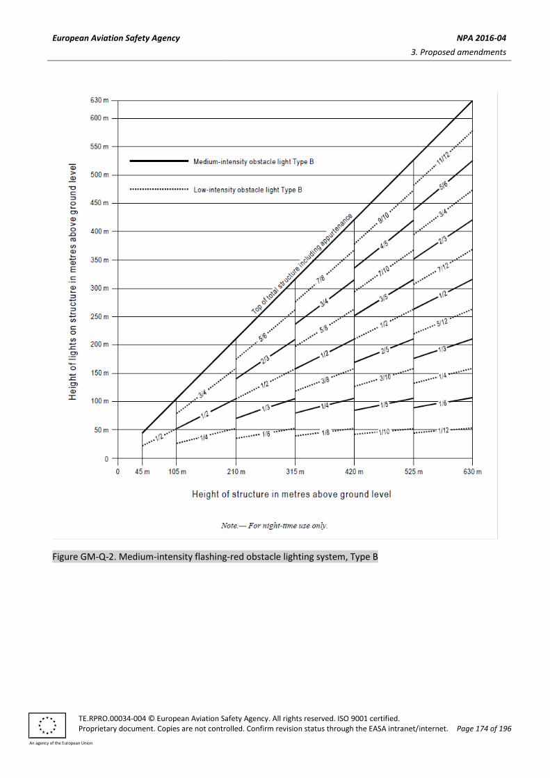
European Aviation Safety Agency NPA 2016-04
3. Proposed amendments
TE.RPRO.00034-004 © European Aviation Safety Agency. All rights reserved. ISO 9001 certified. Proprietary document. Copies are not controlled. Confirm revision status through the EASA intranet/internet. Page 174 of 196
An agency of the European Union
Figure GM-Q-2. Medium-intensity flashing-red obstacle lighting system, Type B

European Aviation Safety Agency NPA 2016-04
3. Proposed amendments
TE.RPRO.00034-004 © European Aviation Safety Agency. All rights reserved. ISO 9001 certified. Proprietary document. Copies are not controlled. Confirm revision status through the EASA intranet/internet. Page 175 of 196
An agency of the European Union
Figure GM-Q-3. Medium-intensity fixed-red obstacle lighting system, Type C

European Aviation Safety Agency NPA 2016-04
3. Proposed amendments
TE.RPRO.00034-004 © European Aviation Safety Agency. All rights reserved. ISO 9001 certified. Proprietary document. Copies are not controlled. Confirm revision status through the EASA intranet/internet. Page 176 of 196
An agency of the European Union
Figure GM-Q-4. Medium-intensity dual obstacle lighting system, Type A/Type B
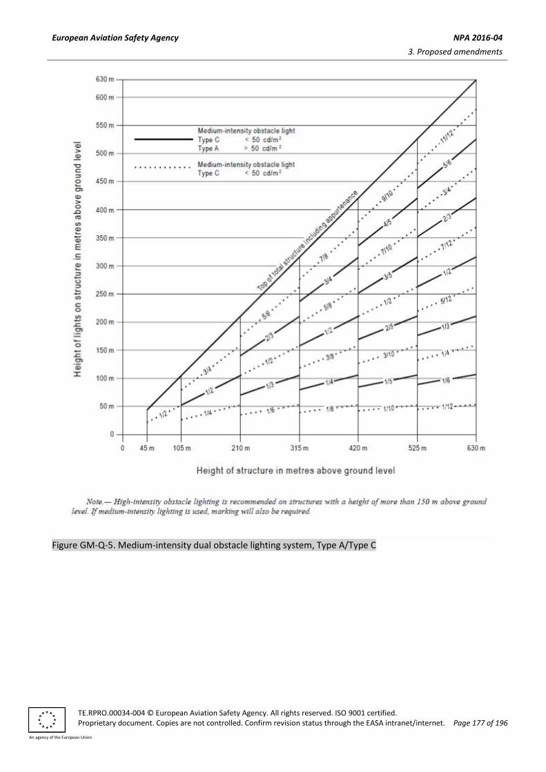
European Aviation Safety Agency NPA 2016-04
3. Proposed amendments
TE.RPRO.00034-004 © European Aviation Safety Agency. All rights reserved. ISO 9001 certified. Proprietary document. Copies are not controlled. Confirm revision status through the EASA intranet/internet. Page 177 of 196
An agency of the European Union
Figure GM-Q-5. Medium-intensity dual obstacle lighting system, Type A/Type C
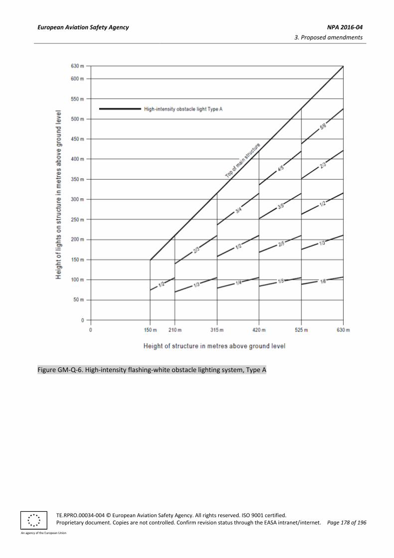
European Aviation Safety Agency NPA 2016-04
3. Proposed amendments
TE.RPRO.00034-004 © European Aviation Safety Agency. All rights reserved. ISO 9001 certified. Proprietary document. Copies are not controlled. Confirm revision status through the EASA intranet/internet. Page 178 of 196
An agency of the European Union
Figure GM-Q-6. High-intensity flashing-white obstacle lighting system, Type A

European Aviation Safety Agency NPA 2016-04
3. Proposed amendments
TE.RPRO.00034-004 © European Aviation Safety Agency. All rights reserved. ISO 9001 certified. Proprietary document. Copies are not controlled. Confirm revision status through the EASA intranet/internet. Page 179 of 196
An agency of the European Union
Figure GM-Q-7. High-/medium-intensity dual obstacle lighting system, Type A/Type B

European Aviation Safety Agency NPA 2016-04
3. Proposed amendments
TE.RPRO.00034-004 © European Aviation Safety Agency. All rights reserved. ISO 9001 certified. Proprietary document. Copies are not controlled. Confirm revision status through the EASA intranet/internet. Page 180 of 196
An agency of the European Union
Figure GM-Q-8. High-/medium-intensity dual obstacle lighting system, Type A/Type C
In the cases as stated in CS ADR-DSN.Q.848(c) and (d), normally the spacing would not exceed 52 m.
Insert new GM1 ADR-DSN.Q.847 as follows:
GM1 ADR-DSN.Q.847 Lighting of fixed objects with a height less than 45 m above ground level
A group of buildings is regarded as an extensive object.

European Aviation Safety Agency NPA 2016-04
3. Proposed amendments
TE.RPRO.00034-004 © European Aviation Safety Agency. All rights reserved. ISO 9001 certified. Proprietary document. Copies are not controlled. Confirm revision status through the EASA intranet/internet. Page 181 of 196
An agency of the European Union
Insert new GM1 ADR-DSN.Q.848 as follows:
GM1 ADR-DSN.Q.848 Lighting of fixed objects with a height 45 m to a height less than 150 m
above ground level
Low-intensity obstacle lights, Type A or B, may be used for obstacles higher than 45 m if it is determined to be sufficient.
Insert new GM1 ADR-DSN.Q.849 as follows:
GM1 ADR-DSN.Q.849 Lighting of fixed objects with a height 150 m or more above ground level
Where, the use of high-intensity obstacle lights, Type A, at night may dazzle pilots in the vicinity of an aerodrome (within approximately 10 000 m radius) or cause significant environmental concerns, medium-intensity obstacle lights, Type C, should be used alone, whereas medium-intensity obstacle lights, Type B, should be used either alone or in combination with low-intensity obstacle lights, Type B.
Amend GM1 ADR-DSN.Q.850 as follows:
GM1 ADR-DSN.Q.850 Lighting of other objects
intentionally left blank (a) High-intensity obstacle lights are intended for day use as well as night use. Care is needed to ensure
that these lights do not create disconcerting dazzle or environmental concerns. Guidance on the design, location, and operation of high-intensity obstacle lights is given in the ICAO Doc 9157, Aerodrome Design Manual, Part 4, Visual Aids.
(b) Low-intensity obstacle lights may be used, Type A or B for obstacles higher than 45 m if it is determined to be sufficient.
(a) A group of trees or buildings is regarded as an extensive object.
Note.— In some cases, this may require locating the lights off the tower.
(b) Guidance Material on how a combination of low, medium, and/or high-intensity lights on obstacles
should be displayed is given in the following Figures:
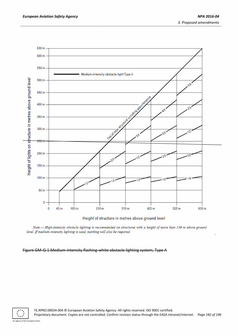
European Aviation Safety Agency NPA 2016-04
3. Proposed amendments
TE.RPRO.00034-004 © European Aviation Safety Agency. All rights reserved. ISO 9001 certified. Proprietary document. Copies are not controlled. Confirm revision status through the EASA intranet/internet. Page 182 of 196
An agency of the European Union
Figure GM-Q-1.Medium-intensity flashing-white obstacle lighting system, Type A

European Aviation Safety Agency NPA 2016-04
3. Proposed amendments
TE.RPRO.00034-004 © European Aviation Safety Agency. All rights reserved. ISO 9001 certified. Proprietary document. Copies are not controlled. Confirm revision status through the EASA intranet/internet. Page 183 of 196
An agency of the European Union
Figure GM-Q-2. Medium-intensity flashing-red obstacle lighting system, Type B

European Aviation Safety Agency NPA 2016-04
3. Proposed amendments
TE.RPRO.00034-004 © European Aviation Safety Agency. All rights reserved. ISO 9001 certified. Proprietary document. Copies are not controlled. Confirm revision status through the EASA intranet/internet. Page 184 of 196
An agency of the European Union
Figure GM-Q-3. Medium-intensity fixed-red obstacle lighting system, Type c

European Aviation Safety Agency NPA 2016-04
3. Proposed amendments
TE.RPRO.00034-004 © European Aviation Safety Agency. All rights reserved. ISO 9001 certified. Proprietary document. Copies are not controlled. Confirm revision status through the EASA intranet/internet. Page 185 of 196
An agency of the European Union
Figure GM-Q-4. Medium-intensity dual obstacle lighting system, Type A/Type B

European Aviation Safety Agency NPA 2016-04
3. Proposed amendments
TE.RPRO.00034-004 © European Aviation Safety Agency. All rights reserved. ISO 9001 certified. Proprietary document. Copies are not controlled. Confirm revision status through the EASA intranet/internet. Page 186 of 196
An agency of the European Union
Figure GM-Q-5. Medium-intensity dual obstacle lighting system, Type A/Type C

European Aviation Safety Agency NPA 2016-04
3. Proposed amendments
TE.RPRO.00034-004 © European Aviation Safety Agency. All rights reserved. ISO 9001 certified. Proprietary document. Copies are not controlled. Confirm revision status through the EASA intranet/internet. Page 187 of 196
An agency of the European Union
Figure GM-Q-6. High-intensity flashing-white obstacle lighting system, Type A

European Aviation Safety Agency NPA 2016-04
3. Proposed amendments
TE.RPRO.00034-004 © European Aviation Safety Agency. All rights reserved. ISO 9001 certified. Proprietary document. Copies are not controlled. Confirm revision status through the EASA intranet/internet. Page 188 of 196
An agency of the European Union
Figure GM-Q-7. High-/medium-intensity dual obstacle lighting system, Type A/Type B

European Aviation Safety Agency NPA 2016-04
3. Proposed amendments
TE.RPRO.00034-004 © European Aviation Safety Agency. All rights reserved. ISO 9001 certified. Proprietary document. Copies are not controlled. Confirm revision status through the EASA intranet/internet. Page 189 of 196
An agency of the European Union
Figure GM-Q-8. High-/medium-intensity dual obstacle lighting system, Type A/Type C
In the cases as stated in CS ADR-DSN.Q.850(c)(7) and (c)(8), normally the spacing would not exceed 52 m.
Insert new GM1 ADR-DSN.Q.851 as follows:
GM1 ADR-DSN.Q.851 Marking and lighting of wind turbines
(a) Additional markings and lighting may be provided to the wind turbines if indicated by a safety
assessment.
(b) Case by case studies for wind turbines of more than 315 m of overall height may conclude that
additional markings and lighting are required.

European Aviation Safety Agency NPA 2016-04
3. Proposed amendments
TE.RPRO.00034-004 © European Aviation Safety Agency. All rights reserved. ISO 9001 certified. Proprietary document. Copies are not controlled. Confirm revision status through the EASA intranet/internet. Page 190 of 196
An agency of the European Union
Insert new GM1 ADR-DSN.Q.852 as follows:
GM1 ADR-DSN.Q.852 Marking and lighting of overhead wires, cables, supporting towers, etc.
(a) Where high-intensity obstacle lights, Type B, are used, and it is not possible to locate them as
described in CS ADR-DSN.Q.852(d)(2), in some cases, this may require locating the lights off the
tower.
(b) High-intensity obstacle lights are intended for day use as well as night use. Care should be taken to
ensure that these lights do not create disconcerting dazzle or environmental concerns. Guidance on
the design, location, and operation of high-intensity obstacle lights is given in ICAO Doc 9157,
Aerodrome Design Manual, Part 4, Visual Aids.
(c) Where the use of high-intensity obstacle lights, Type B, at night may dazzle pilots in the vicinity of an aerodrome (within approximately 10 000 m radius) or cause significant environmental concerns, a dual obstacle lighting system should be provided. This system should be composed of high-intensity obstacle lights, Type B, for daytime and twilight use and medium-intensity obstacle lights, Type B, for night-time use. Where medium-intensity lights are used they should be installed at the same level as the high-intensity obstacle light Type B.
Amend GM1 ADR-DSN.R.855 as follows:
GM1 ADR-DSN.R.855 Closed runways and taxiways, or parts thereof
iIntentionally left blank
Amend GM1 ADR-DSN.R.860 as follows:
GM1 ADR-DSN.R.860 Non-load-bearing surfaces
The marking characteristics of runway sides is specified in CS ADR-DSN.L.550.
(a) A taxi side stripe marking could also be placed along the edge of the load-bearing pavement to emphasise the location of the taxiway edge, with the outer edge of the marking approximately on the edge of the load-bearing pavement.
(b) At intersections of taxiways and on other areas where, due to turning, the possibility for confusion between the side stripe markings and centre line markings may exist, or where the pilot may not be sure on which side of the edge marking the non-load bearing pavement is, the additional provision of transverse stripes on the non-load bearing surface has been found to be of assistance.
(c) As shown in Figure GM-R-1, the transverse stripes should be placed perpendicular to the side stripe marking.
(d) On curves, a stripe should be placed at each point of tangency of the curve and at intermediate points along the curve so that the interval between stripes does not exceed 15 m. If deemed desirable to place transverse stripes on small straight sections, the spacing should not exceed 30 m.

European Aviation Safety Agency NPA 2016-04
3. Proposed amendments
TE.RPRO.00034-004 © European Aviation Safety Agency. All rights reserved. ISO 9001 certified. Proprietary document. Copies are not controlled. Confirm revision status through the EASA intranet/internet. Page 191 of 196
An agency of the European Union
(e) The width of the marks should be 0.9 m, and they should extend to within 1.5 m of the outside edge of the stabilised paving or be 7.5 m long whichever is shorter. The colour of the transverse stripes should be the same as that of the edge stripes, i.e. yellow.
Figure GM-R-1. Marking of non-load bearing paved taxiway surface
More guidance on providing additional transverse stripes at an intersection or a small area on the apron is given in the ICAO Doc 9157, Aerodrome Design Manual, Part 4, Visual Aids).

European Aviation Safety Agency NPA 2016-04
3. Proposed amendments
TE.RPRO.00034-004 © European Aviation Safety Agency. All rights reserved. ISO 9001 certified. Proprietary document. Copies are not controlled. Confirm revision status through the EASA intranet/internet. Page 192 of 196
An agency of the European Union
Amend GM1 ADR-DSN.S.875 as follows:
GM1 ADR-DSN.S.875 Electrical power supply systems for air navigation facilities
(...)
(b) The design and installation of the electrical systems need to take into consideration factors that can lead
to malfunction, such as electromagnetic disturbances, line losses, power quality, etc. Additional
guidance is given in the ICAO Doc 9157, Aerodrome Design Manual, Part 5, Electrical Systems).
(c) Switch-over time is the time required for the actual intensity of a light measured in a given direction to
fall from 50 % and recover to 50 % during a power supply changeover, when the light is being operated
at intensities of 25 % or above.
(d) As a good practice, a measurement of the photometric parameters may be used for the evaluation of the switch-over time.
(1) If the switch-over time is greater than 1 second, the following corrective actions may be used to decrease the switch-over time:
(i) use of enhanced constant current regulators (CCR); or
(ii) use of uninterruptible power supply (UPS).
(2) If the photometric based switch-over time is below or equal 1 second, it is recommended to analyse the electrical system in order to find out an equivalent electrical switch-over time.
(e) For periodic measurement of the switch-over time a measurement of the equivalent electrical switch-over time at the feeding point of an aeronautical ground lights (AGL) system should be established.
Amend GM1 ADR-DSN.S.880 as follows:
GM1 ADR-DSN.S.880 Electrical power supply for visual aids
(a) At an aerodrome where the primary runway is a non-instrument runway, a secondary power supply capable of meeting the requirements of CS ADR-DSN.S.875(d) should be provided, except that a secondary power supply for visual aids need not be provided when an emergency lighting system is provided and capable of being deployed in 15 minutes.
(b)(a) Specifications for secondary power supply for radio navigation aids and ground elements of communications systems are given in ICAO Annex 10, Volume I, Aeronautical Telecommunications, Chapter 2.
(c)(b) Requirements for a secondary power supply should be met by either of the following:
(1) independent public power which is a source of power supplying the aerodrome service from a
substation other than the normal substation through a transmission line following a route
different from the normal power supply route and such that the possibility of a simultaneous
failure of the normal and independent public power supplies is extremely remote; or
(2) standby power unit(s) which are engine generators, batteries, etc. from which electric power can
be obtained.
(d)(c) Guidance on electrical systems is included in the ICAO Doc 9157, Aerodrome Design Manual, Part 5, Electrical Systems.

European Aviation Safety Agency NPA 2016-04
3. Proposed amendments
TE.RPRO.00034-004 © European Aviation Safety Agency. All rights reserved. ISO 9001 certified. Proprietary document. Copies are not controlled. Confirm revision status through the EASA intranet/internet. Page 193 of 196
An agency of the European Union
(e)(d) The requirement for minimum lighting may be met by other than electrical means.
Amend GM1 ADR-DSN.S.885 as follows:
GM1 ADR-DSN.S.885 System design
Guidance on means of providing this protection is given in the ICAO Doc 9157, Aerodrome Design Manual, Part 5, Electrical Systems.
Amend GM1 ADR-DSN.S.890 as follows:
GM1 ADR-DSN.S.890 Monitoring
(a) For a runway meant for use in runway visual range conditions less than a value of 550 m, the minimum
serviceability level of any element of the lighting system detailed in Table S-1, below which operations
should not continue, is normally set up by the appropriate authority.
(b) Additional gGuidance on this subject and on air traffic control interface and visual aids monitoring is
given included in the ICAO Doc 9157, Aerodrome Design Manual, Part 5, Electrical Systems.
Amend GM1 ADR-DSN.S.895 as follows:
GM1 ADR-DSN.S.895 Serviceability levels
(a) Serviceability levels are intended to define the maintenance performance level objectives. They are not
intended to define whether the lighting system is operationally out of service.
(b) Guidance on preventive maintenance of visual aids is given in the, ICAO Doc 9137, Airport Services
Manual, Part 96, Airport Maintenance Practices.
(...)
Amend GM1 ADR-DSN.T.900 as follows:
GM1 ADR-DSN.T.900 Emergency access and service access roads
(...)
(b) Some general considerations in the planning of roads are described as follows:
(...)
(2) The planning of the aerodrome road layout should take into account the need to provide
emergency access roads for use by rescue and firefighting vehicles to various areas on the
aerodrome, and, in particular, to the approach areas. Service roads to navigation aids should be
planned in such a manner as to present minimal interference to the function of the aids. If it is

European Aviation Safety Agency NPA 2016-04
3. Proposed amendments
TE.RPRO.00034-004 © European Aviation Safety Agency. All rights reserved. ISO 9001 certified. Proprietary document. Copies are not controlled. Confirm revision status through the EASA intranet/internet. Page 194 of 196
An agency of the European Union
necessary for an service road to cross an approach area, the road should be located so that
vehicles travelling on it are not obstacles to aircraft operations.
(...)
(...)
(d) Emergency access roads should be provided on an aerodrome where terrain conditions permit their
construction, so as to facilitate achieving minimum response times. Particular attention should be given
to the provision of ready access to approach areas up to 1 000 m from the threshold, or at least within
the aerodrome boundary.
(...)
Amend GM1 ADR-DSN.T.905 as follows:
GM1 ADR-DSN.T.905 Fire stations
iIntentionally left blank
Amend GM1 ADR-DSN.T.910 as follows:
GM1 ADR-DSN.T.910 Equipment frangibility requirements
(...)
(c) Guidance on design for frangibility is contained in the ICAO Doc 9157, Aerodrome Design Manual, Part 6,
Frangibility.
Amend GM1 ADR-DSN.T.915 as follows:
GM1 ADR-DSN.T.915 Siting of equipment and installations on operational areas
(...)
(b) Guidance on siting of equipment and installations on operational areas is given in ICAO Doc 9157,
Aerodrome Design Manuals, Part 2, Taxiways, Aprons and Holding Bays and Part 6, Frangibility).
(c) Guidance on the frangible design of visual and non-visual aids for navigation is given in the ICAO Ddoc
9157, Aerodrome Design Manual, Part 56, Electrical Systems).
(...)
Amend GM1 ADR-DSN.T.920 as follows:
GM1 ADR-DSN.T.920 Fencing

European Aviation Safety Agency NPA 2016-04
3. Proposed amendments
TE.RPRO.00034-004 © European Aviation Safety Agency. All rights reserved. ISO 9001 certified. Proprietary document. Copies are not controlled. Confirm revision status through the EASA intranet/internet. Page 195 of 196
An agency of the European Union
(...)
(e) Top and bottom selvages of the fence having a twisted and barbed finish. The bottom of the fence
installed to within 5 cm of hard surfacing or stabilised soil. However, in areas where unstable soil
conditions are prevalent, the fabric installed to extend at least 5 cm below the surface or imbedded in
concrete curbing. All fencing should be grounded. Care should be taken that metallic fencing is not
installed when it should interface with the operation of navigation aids. The fence itself should allow is
low maintenance, provides clear visibility and easy maintenance.
(...)
Amend GM1 ADR-DSN.U.930 as follows:
GM1 ADR-DSN.U.930 Colours for aeronautical ground lights
(...) (b) Guidance on chromaticity changes resulting from the effect of temperature on filtering elements is
given in ICAO Doc 9157, Aerodrome Design Manual, Part 4, Visual Aids.
Amend GM1 ADR-DSN.U.935 as follows:
GM1 ADR-DSN.U.935 Colours for markings, signs and panels
iIntentionally left blank
Amend GM1 ADR-DSN.U.940 as follows:
GM1 ADR-DSN.U.940 Aeronautical ground light characteristics
iIntentionally left blank

European Aviation Safety Agency NPA 2016-04
4. References
TE.RPRO.00034-004 © European Aviation Safety Agency. All rights reserved. ISO 9001 certified. Proprietary document. Copies are not controlled. Confirm revision status through the EASA intranet/internet. Page 196 of 196
An agency of the European Union
4. References
Affected regulations 4.1.
N/A
Affected decision 4.2.
Executive Director Decision 2015/001/R of 29 January 2015 amending Certification Specifications and
Guidance Material for Aerodrome Design (CS-ADR-DSN — Issue 2).
Reference documents 4.3.
ICAO Annex 14, Aerodromes, Volume I Aerodrome Design and Operations, Sixth edition, July 2013

European Aviation Safety Agency NPA 2016-XX
5. Appendices
TE.RPRO.00034-004 © European Aviation Safety Agency. All rights reserved. ISO 9001 certified. Proprietary document. Copies are not controlled. Confirm revision status through the EASA intranet/internet. Page 197 of 196
An agency of the European Union
5. Appendices
N/A