Embed Size (px)
Citation preview
New
pre
sent
atio
n -
see
His
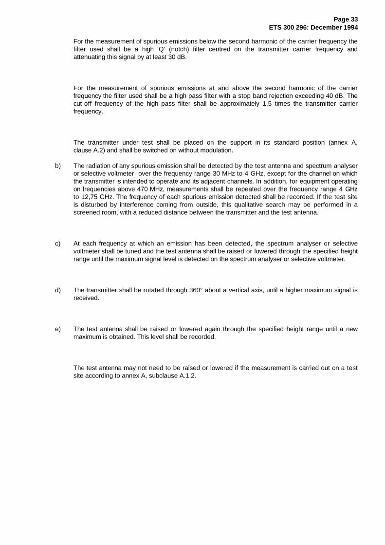
tory
box
EUROPEAN ETS 300 296
TELECOMMUNICATION December 1994
STANDARD
Source: ETSI TC-RES Reference: DE/RES-02-07
ICS: 33.060.20
Key words: Land Mobile radio, analogue speech, integral antenna, testing
Radio Equipment and Systems (RES);Land mobile service
Technical characteristics and test conditions forradio equipment using integral antennasintended primarily for analogue speech
ETSIEuropean Telecommunications Standards Institute
ETSI Secretariat
Postal address: F-06921 Sophia Antipolis CEDEX - FRANCEOffice address: 650 Route des Lucioles - Sophia Antipolis - Valbonne - FRANCEX.400: c=fr, a=atlas, p=etsi, s=secretariat - Internet: [email protected]
Tel.: +33 92 94 42 00 - Fax: +33 93 65 47 16
Copyright Notification: No part may be reproduced except as authorized by written permission. The copyright and theforegoing restriction extend to reproduction in all media.
© European Telecommunications Standards Institute 1994. All rights reserved.
Page 2ETS 300 296: December 1994
Whilst every care has been taken in the preparation and publication of this document, errors in content,typographical or otherwise, may occur. If you have comments concerning its accuracy, please write to"ETSI Editing and Committee Support Dept." at the address shown on the title page.
Page 3ETS 300 296: December 1994
Contents
Foreword ........................................................................................................................................... 7
Introduction ........................................................................................................................................ 7
1 Scope ...................................................................................................................................... 9
2 Normative references .............................................................................................................. 10
3 Definitions, abbreviations and symbols ...................................................................................... 103.1 Definitions................................................................................................................. 103.2 Abbreviations............................................................................................................ 11
3.3 Symbols ................................................................................................ 11
4 General .................................................................................................................................. 124.1 Presentation of equipment for testing purposes ........................................................... 12
4.1.1 Choice of model for type approval ........................................................... 124.1.2 Definitions of alignment range and switching range.................................... 124.1.3 Definition of the categories of the alignment range (AR1 and AR2)............. 124.1.4 Choice of frequencies ............................................................................. 124.1.5 Testing of single channel equipment of category AR1................................ 134.1.6 Testing of single channel equipment of category AR2................................ 134.1.7 Testing of two channel equipment of category AR1................................... 134.1.8 Testing of two channel equipment of category AR2................................... 134.1.9 Testing of multi-channel equipment (more than two channels) of category
AR1 ...................................................................................................... 144.1.10 Testing of multi-channel equipment (more than two channels) of category
AR2 (switching range less than alignment range) ...................................... 144.1.11 Testing of multi-channel equipment (more than two channels) of category
AR2 (switching range equals the alignment range) .................................... 144.2 Mechanical and electrical design ................................................................................ 14
4.2.1 General ................................................................................................. 144.2.2 Controls................................................................................................. 144.2.3 Transmitter shut-off facility ...................................................................... 154.2.4 Marking ................................................................................................. 15
4.3 Interpretation of the measurement results ................................................................... 15
5 Technical characteristics.......................................................................................................... 155.1 Transmitter parameter limits ...................................................................................... 15
5.1.1 Frequency error ..................................................................................... 155.1.2 Effective radiated power......................................................................... 165.1.3 Frequency deviation................................................................................ 17
5.1.3.1 Maximum permissible frequency deviation......................... 175.1.4 Adjacent channel power.......................................................................... 185.1.5 Spurious emissions................................................................................. 195.1.6 Transient frequency behaviour of the transmitter....................................... 19
5.2 Receiver parameter limits .......................................................................................... 195.2.1 Average usable sensitivity (field strength, speech) .................................... 195.2.2 Amplitude characteristic.......................................................................... 205.2.3 Co-channel rejection ............................................................................... 205.2.4 Adjacent channel selectivity..................................................................... 215.2.5 Spurious response rejection .................................................................... 215.2.6 Intermodulation response rejection........................................................... 215.2.7 Blocking or desensitisation ...................................................................... 21
Page 4ETS 300 296: December 1994
5.2.8 Spurious radiations ................................................................................. 22
6 Test conditions, power sources and ambient temperatures......................................................... 226.1 Normal and extreme test conditions ............................................................................ 226.2 Test power source .................................................................................................... 226.3 Normal test conditions ............................................................................................... 22
6.3.1 Normal temperature and humidity............................................................. 226.3.2 Normal test power source ....................................................................... 23
6.3.2.1 Mains voltage ................................................................. 236.3.2.2 Regulated lead-acid battery power sources used on
vehicles.......................................................................... 236.3.2.3 Other power sources ...................................................... 23
6.4 Extreme test conditions.............................................................................................. 236.4.1 Extreme temperatures ............................................................................ 236.4.2 Extreme test source voltages .................................................................. 23
6.4.2.1 Mains voltage ................................................................. 236.4.2.2 Regulated lead-acid battery power sources used on
vehicles.......................................................................... 236.4.2.3 Power sources using other types of batteries.................... 236.4.2.4 Other power sources ...................................................... 24
6.5 Procedure for tests at extreme temperatures .............................................................. 246.5.1 Procedure for equipment designed for continuous operation....................... 246.5.2 Procedure for equipment designed for intermittent operation...................... 24
7 General conditions................................................................................................................... 257.1 Test modulation......................................................................................................... 257.2 Artificial antenna........................................................................................................ 257.3 Test sites and general arrangements for radiated measurements.................................. 257.4 Transmitter automatic shut-off facility.......................................................................... 257.5 Arrangement for test signals at the input of the transmitter ........................................... 257.6 Arrangements for test signals at the input of the receiver via a test fixture or a test
antenna .................................................................................................................... 257.7 Receiver mute or squelch facility................................................................................. 257.8 Receiver rated audio output power ............................................................................. 26
8 Methods of measurement for transmitter parameters ................................................................. 268.1 Frequency error ........................................................................................................ 26
8.1.1 Definition................................................................................................ 268.1.2 Method of measurement ........................................................................ 26
8.2 Effective radiated power............................................................................................ 268.2.1 Definition................................................................................................ 268.2.2 Method of measurement ......................................................................... 27
8.2.2.1 Maximum effective radiated power under normal testconditions....................................................................... 27
8.2.2.2 Average effective radiated power under normal testconditions....................................................................... 28
8.2.3 Method of measurements of maximum and average effective radiatedpower under extreme test conditions........................................................ 29
8.3 Frequency deviation................................................................................................... 298.3.1 Maximum permissible frequency deviation ................................................ 29
8.3.1.1 Definition........................................................................ 298.3.1.2 Method of measurement.................................................. 308.3.1.3 Analogue signals within the audio bandwidth ..................... 308.3.1.4 Analogue signals above the audio bandwidth..................... 30
8.4 Adjacent channel power............................................................................................ 318.4.1 Definition................................................................................................ 318.4.2 Method of measurement ......................................................................... 31
8.5 Radiated spurious emissions ...................................................................................... 328.5.1 Definition................................................................................................ 328.5.2 Method of measurement ......................................................................... 32
Page 5ETS 300 296: December 1994
8.6 Transient frequency behaviour of the transmitter.......................................................... 358.6.1 Definitions.............................................................................................. 358.6.2 Method of measurement ......................................................................... 35
9 Methods of measurement for receiver parameters..................................................................... 399.1 Average usable sensitivity (field strength, speech) ....................................................... 39
9.1.1 Definition ............................................................................................... 399.1.2 Method of measurement under normal test conditions ............................... 399.1.3 Method of measurement under extreme test conditions ............................. 419.1.4 Reference for degradation measurements................................................ 41
9.1.4.1 Definition........................................................................ 419.1.4.2 Procedures for measurements using the test fixture .......... 419.1.4.3 Procedures for measurements using the test site .............. 42
9.2 Amplitude characteristic of receiver limiter................................................................... 429.2.1 Definition ............................................................................................... 429.2.2 Method of measurement ......................................................................... 42
9.3 Co-channel rejection.................................................................................................. 439.3.1 Definition ............................................................................................... 439.3.2 Method of measurement ......................................................................... 43
9.4 Adjacent channel selectivity........................................................................................ 449.4.1 Definition ............................................................................................... 449.4.2 Method of measurement ......................................................................... 44
9.5 Spurious response rejection ....................................................................................... 459.5.1 Definition ............................................................................................... 459.5.2 Introduction to the method of measurement .............................................. 459.5.3 Measurement arrangement ..................................................................... 479.5.4 Method of the search.............................................................................. 489.5.5 Method of measurement ......................................................................... 49
9.6 Intermodulation response rejection ............................................................................. 499.6.1 Definition ............................................................................................... 499.6.2 Method of measurement ......................................................................... 50
9.7 Blocking or desensitisation......................................................................................... 519.7.1 Definition ............................................................................................... 519.7.2 Method of measurement ......................................................................... 51
9.8 Spurious radiations.................................................................................................... 529.8.1 Definition ............................................................................................... 529.8.2 Method of measurement ......................................................................... 53
10 Measurement uncertainty ......................................................................................................... 55
Annex A (normative): Radiated measurements.............................................................................. 56
A.1 Test sites and general arrangements for measurements involving the use of radiated fields .......... 56A.1.1 Open air test site ...................................................................................................... 56
A.1.1.1 Description ............................................................................................ 56A.1.1.2 Establishment of a relationship between signal levels and field strength ...... 57
A.1.2 Anechoic chamber..................................................................................................... 57A.1.2.1 General ................................................................................................. 57A.1.2.2 Description ............................................................................................ 58A.1.2.3 Influence of parasitic reflections............................................................... 58A.1.2.4 Mode of use .......................................................................................... 58
A.1.3 Stripline arrangement ................................................................................................ 60A.1.3.1 General ................................................................................................. 60A.1.3.2 Description ............................................................................................ 60A.1.3.3 Calibration ............................................................................................. 60A.1.3.4 Mode of use .......................................................................................... 60
A.1.4 Indoor test site.......................................................................................................... 61A.1.4.1 Description ............................................................................................ 61A.1.4.2 Test for parasitic reflections.................................................................... 62
Page 6ETS 300 296: December 1994
A.1.4.3 Mode of use........................................................................................... 62
A.2 Standard position .................................................................................................................... 62
A.3 Acoustic coupler...................................................................................................................... 63A.3.1 General .................................................................................................................... 63A.3.2 Description ............................................................................................................... 63A.3.3 Calibration ................................................................................................................ 63
A.4 Test antenna........................................................................................................................... 65
A.5 Substitution antenna................................................................................................................. 65
A.6 Test fixture.............................................................................................................................. 65A.6.1 Description ............................................................................................................... 65A.6.2 Calibration ................................................................................................................ 66A.6.3 Mode of use ............................................................................................................. 66
A.7 Bibliography ............................................................................................................................ 67
Annex B (normative): Specifications for adjacent channel power measurement arrangements ........... 68
B.1 Power measuring receiver specification..................................................................................... 68B.1.1 General .................................................................................................................... 68B.1.2 IF filter ..................................................................................................................... 68B.1.3 Oscillator and amplifier .............................................................................................. 70B.1.4 Attenuation indicator .................................................................................................. 70B.1.5 Level indicators ......................................................................................................... 70
B.1.5.1 Rms level indicator ................................................................................. 70B.1.5.2 Peak level indicator................................................................................. 70
Annex C (normative): Graphic representation of the selection of equipment and frequencies fortesting........................................................................................................ 71
Annex D (normative): Test discriminator........................................................................................ 73
D.1 Characteristics of the test discriminator..................................................................................... 73
History ............................................................................................................................................. 74
Page 7ETS 300 296: December 1994
Foreword
This European Telecommunication Standard (ETS) has been prepared by the Radio Equipment andSystems (RES) Technical Committee of the European Telecommunications Standards Institute (ETSI).
Annex A provides additional information concerning radiated measurements.
Annex B contains normative specifications for adjacent channel power measurement arrangements.
Annex C is a graphic representation of the normative subclause 4.1, referring to the presentation ofequipment for testing purposes.
Annex D contains specifications for the test discriminator used in transient measurements.
Transposition datesDate of latest announcement of this ETS (doa):
Date of latest publication of new National Standard
or endorsement of this ETS (dop/e):
Date of withdrawal of any conflicting National Standard (dow):
31 March 1995
30 September 1995
30 September 1995
Introduction
This ETS was drafted on the assumption that:
- the type test measurements performed in an accredited test laboratory in one country would beaccepted by the Type Approval Authority in another country provided that the national regulatoryrequirements are met;
- if equipment available on the market is required to be checked it should be tested in accordancewith the methods of measurement specified in this ETS.

Page 8ETS 300 296: December 1994
Blank page
Page 9ETS 300 296: December 1994
1 Scope
This ETS is intended to specify the minimum performance and the methods of measurement of radioequipment for use in the land mobile service as specified in the Scope. Clause 5 provides thecorresponding limits. These limits have been chosen to ensure an acceptable grade of service and tominimise harmful interference to other equipment and services. They are based on the interpretation of themeasurement results described in subclause 4.3.
This ETS covers the minimum characteristics considered necessary in order to make the best use of theavailable frequencies. It does not necessarily include all the characteristics which may be required by auser, nor does it necessarily represent the optimum performance achievable. It applies to equipment withintegral antennas, used in angle modulation systems in the land mobile service, operating on radiofrequencies between 30 MHz and 1 000 MHz, with channel separations of 12,5 kHz, 20 kHz and 25 kHz,and is intended primarily for analogue speech.
This ETS is based upon CEPT Recommendation T/R 24-01 annex III [1], and is a general standard whichmay be superseded by specific standards covering specific applications.
In this ETS different requirements are given for the different radio frequency bands, channel separations,environmental conditions and types of equipment, where appropriate.
The measurement methods have been adapted from ETR 027 [3] where possible.
The type of equipment covered by this ETS is handportable stations with integral antennas.
This ETS covers angle modulation to be used for radio equipment, but individual national administrationsare free to choose the type of modulation. Channel separations, maximum transmitter outputpower/effective radiated power and the inclusion of automatic transmitter shut-off facility may all beconditions attaching to the issue of a licence by the appropriate administration.
This ETS is complementary to ETS 300 086 [2] which covers radio equipment with an internal or externalRF connector, for use in the land mobile service. It is primarily intended for omnidirectional applications.
Equipment which also includes an external or internal RF connector should be type tested to therequirements of ETS 300 086 [2] using this connector.
Additional standards or specifications may be required for equipment such as that intended for connectionto the Public Switched Telephone Network (PSTN).
This ETS does not cover requirements for radiated emissions below 30 MHz.
This ETS may also be used by accredited test laboratories for the assessment of the performance of theequipment. The performance of the equipment submitted for type testing should be representative for theperformance of the corresponding production model. In order to avoid any ambiguity in that assessment,this ETS contains instructions for the presentation of equipment for type testing purposes (clause 4),conditions (clause 6) and measurement methods (clauses 8 and 9).
Page 10ETS 300 296: December 1994
2 Normative references
This ETS incorporates by date or undated reference, provisions from other publications. These normativereferences are cited at the appropriate places in the text and the publications listed hereafter. For datedreferences, subsequent amendments to or revisions of any of these publications apply to this ETS onlywhen incorporated in it by amendment or revision. For undated references the latest edition of thepublication referred to applies.
[1] CEPT Recommendation T/R 24-01 annex III: "Technical characteristics and testconditions for radio equipment using integral antenna in the Land MobileService".
[2] ETS 300 086: "Radio Equipment and Systems; Land mobile service: Technicalcharacteristics and test conditions for radio equipment with an internal orexternal RF connector intended primarily for analogue speech".
[3] ETR 027: "Radio Equipment and Systems; Methods of measurement for mobileradio equipment".
[4] ETR 028: "Radio Equipment and Systems; Uncertainties in the measurement ofmobile radio equipment characteristics".
[5] CCITT Recommendation Blue Book O.41 (1988): "Psophometer for use ontelephone-type circuits".
3 Definitions, abbreviations and symbols
3.1 Definitions
For the purpose of this ETS, the following definitions apply:
angle modulation: Either phase modulation (G3) or frequency modulation (F3).
audio frequency load: The audio frequency load is normally a resistor of sufficient power rating to acceptthe maximum audio output power from the equipment under test. The value of this resistor should be thatstated by the manufacturer and equal to the impedance of the audio transducer at 1 000 Hz. In somecases it may be necessary to place an isolating transformer between the output terminals of the receiverunder test and the load.
audio frequency termination: The audio frequency termination is any connection other than the audiofrequency load which may be required for the purpose of testing the receiver. The termination deviceshould be agreed between the manufacturer and the testing laboratory and details included in the testreport. If special equipment is required then it should be provided by the manufacturer.
band -stop filter (for the SINAD meter): The characteristics of the band-stop filter used in the audiodistortion factor meter and SINAD meter should be such that at the output the 1 000 Hz tone will beattenuated by at least 40 dB and at 2 000 Hz the attenuation will not exceed 0,6 dB. The filtercharacteristic shall be flat within 0,6 dB over the ranges 20 Hz to 500 Hz and 2 000 Hz to 4 000 Hz. In theabsence of modulation the filter must not cause more than 1 dB attenuation of the total noise power of theaudio frequency output of the receiver under test.
integral antenna: An antenna designed to be connected to the equipment without the use of a 50 Ωexternal connector and considered to be part of the equipment. An integral antenna may be fitted internallyor externally to the equipment.
psophometric weighting network: The psophometric weighting network is described in CCITTRecommendation Blue Book O.41 [5].
Page 11ETS 300 296: December 1994
Types of measurements:
conducted measurements: Measurements which are made using a direct connection to theequipment under test.
radiated measurements: Measurements which involve the absolute measurement of a radiatedfield.
Types of station:
base station: Equipment fitted with an antenna socket, for use with an external antenna andintended for use in a fixed location.
handportable station: Equipment either fitted with an antenna socket or an integral antenna, orboth, normally used on a stand-alone basis, to be carried on a person or held in the hand.
mobile station: Mobile equipment fitted with an antenna socket, for use with an external antenna,normally used in a vehicle or as a transportable station.
Types of tests:
full tests: In all cases except where qualified as "limited", tests are performed according to thisETS.
limited tests : The limited tests, subclause 4.1, are as follows:
- receiver average usable sensitivity (field strength), subclause 9.1;- receiver adjacent channel selectivity, subclause 9.4;- transmitter frequency error, subclause 8.1;- transmitter effective radiated power, subclause 8.2;- transmitter adjacent channel power, subclause 8.4.
3.2 Abbreviations
AR1 (see subclause 4.1.3)AR2 (see subclause 4.1.3)dBc dB relative to the carrier poweremf electro-motive forceIF Intermediate FrequencyRF Radio FrequencyRx ReceiverSINAD (signal + noise + distortion)/(noise + distortion)Tx TransmitterVSWR Voltage Standing Wave Ratio
3.3 Symbols
Eo Reference field strength (see annex A)Ro Reference distance (see annex A)
Page 12ETS 300 296: December 1994
4 General
4.1 Presentation of equipment for testing purposes
Each equipment submitted for type testing shall fulfil the requirements of this ETS on all channels overwhich it is intended to operate.
To simplify and harmonise the type testing procedures between the different test laboratories,measurements shall be performed, according to this ETS, on samples of equipment defined in subclauses4.1.1 to 4.1.11.
These clauses are intended to give confidence that the requirements set out in this ETS have been metwithout the necessity of performing measurements on all channels.
4.1.1 Choice of model for type approval
The manufacturer shall provide one or more production model(s) of the equipment, as appropriate, for typeapproval testing.
If type approval is given on the basis of tests on a preliminary model, then the corresponding productionmodels shall be identical in all respects with the preliminary model tested.
4.1.2 Definitions of alignment range and switching range
The manufacturer shall, when submitting equipment for test, state the alignment ranges for the receiverand the transmitter.
The alignment range is defined as the frequency range over which the receiver and the transmitter can beprogrammed and/or realigned to operate, without any physical change of components other thanprogrammable read only memories or crystals (for the receiver and the transmitter).
The manufacturer shall also state the switching range of the receiver and the transmitter (which maydiffer).
The switching range is the maximum frequency range over which the receiver or the transmitter can beoperated without reprogramming or realignment.
For the purpose of all measurements, the receiver and transmitter shall be considered separately.
4.1.3 Definition of the categories of the alignment range (AR1 and AR2)
The alignment range falls into one of two categories.
The first category corresponds to a limit of the alignment range, of the receiver and the transmitter, whichis less than 10 % of the highest frequency of the alignment range for equipment operating on frequenciesup to 500 MHz, or less than 5 % for equipment operating above 500 MHz. This category is defined asAR1.
The second category corresponds to an alignment range of the receiver and transmitter which is greaterthan 10 % of the highest frequency of the alignment range for equipment on frequencies up to 500 MHz, orgreater than 5 % for equipment operating above 500 MHz. This category is defined as AR2.
4.1.4 Choice of frequencies
The frequencies for testing shall be chosen by the manufacturer in consultation with the appropriateauthority, in accordance with subclauses 4.1.5 to 4.1.11 and annex C. The manufacturer selects thefrequencies for testing and will ensure that the chosen frequencies are within one or more of the nationalbands for which type approval is required.
Page 13ETS 300 296: December 1994
4.1.5 Testing of single channel equipment of category AR1
In the case of single channel equipment of the category AR1, one sample of the equipment shall be tested.
Full tests shall be carried out on a channel within 100 kHz of the centre frequency of the alignment range.
4.1.6 Testing of single channel equipment of category AR2
In the case of single channel equipment of the category AR2, three samples of the equipment shall betested. Tests shall be carried out on a total of three channels.
The frequency of the channel of the first sample shall be within 100 kHz of the highest frequency of thealignment range.
The frequency of the channel of the second sample shall be within 100 kHz of the lowest frequency of thealignment range.
The frequency of the channel of the third sample shall be within 100 kHz of the centre frequency of thealignment range.
Full tests shall be carried out on all three channels.
4.1.7 Testing of two channel equipment of category AR1
In the case of two channel equipment of category AR1, one sample of the equipment shall be tested.Tests shall be carried out on the two channels.
The frequency of the upper channel shall be within 100 kHz of the highest frequency of the switching range.
The frequency of the lower channel shall be within 100 kHz of the lowest frequency of the switching range.In addition the average of the frequencies of the two channels shall be within 100 kHz of the centrefrequency of the alignment range.
Full tests shall be carried out on the upper channel and limited tests on the lower channel.
4.1.8 Testing of two channel equipment of category AR2
In the case of two channel equipment of the category AR2, three samples of the equipment shall betested.
Tests shall be carried out on a total of four channels.
The highest frequency of the switching range of one sample shall be within 100 kHz of the centre frequencyof the alignment range. The frequency of the upper channel shall be within 100 kHz of the highestfrequency of the switching range and the frequency of the lower channel shall be within 100 kHz of thelowest frequency of the switching range.
Full tests shall be carried out on the upper channel and limited tests on the lower channel.
The frequency of one of the channels of the second sample shall be within 100 kHz of the highestfrequency of the alignment range.
Full tests shall be carried out on this channel.
The frequency of one of the channels of the third sample shall be within 100 kHz of the lowest frequency ofthe alignment range.
Full tests shall be carried out on this channel.
Page 14ETS 300 296: December 1994
4.1.9 Testing of multi-channel equipment (more than two channels) of category AR1
In the case of multi-channel equipment of the category AR1, one sample of the equipment shall be tested.
The centre frequency of the switching range of the sample shall correspond to the centre frequency of thealignment range.
Full tests shall be carried out on a frequency within 100 kHz of the centre frequency of the switching range.Limited tests shall be carried out within 100 kHz of the lowest and also within 100 kHz of the highestfrequency of the switching range.
4.1.10 Testing of multi-channel equipment (more than two channels) of category AR2(switching range less than alignment range)
In the case of multi-channel equipment of the category AR2 with switching range less than the alignmentrange, three samples of the equipment shall be tested.
Tests shall be carried out on a total of five channels.
The centre frequency of the switching range of one sample shall be within 100 kHz of the centre frequencyof the alignment range. The frequency of the upper channel shall be within 100 kHz of the highestfrequency of the switching range and the frequency of the lower channel shall be within 100 kHz of thelowest frequency of the switching range.
Full tests shall be carried out on the centre channel and limited tests on the upper and lower channel.
The frequency of one of the channels of the second sample shall be within 100 kHz of the highestfrequency of the alignment range.
Full tests shall be carried out on this channel.
The frequency of one of the channels of the third sample shall be within 100 kHz of the lowest frequency ofthe alignment range.
Full tests shall be carried out on this channel.
4.1.11 Testing of multi-channel equipment (more than two channels) of category AR2(switching range equals the alignment range)
In the case of multi-channel equipment of the category AR2 with switching range equal to the alignmentrange, one sample of the equipment shall be tested.
The centre frequency of the switching range of the sample shall correspond to the centre frequency of thealignment range.
Full tests shall be carried out on a frequency within 100 kHz of the centre frequency of the switching rangeand within 100 kHz of the lowest and also within 100 kHz of the highest frequency of the switching range.
4.2 Mechanical and electrical design
4.2.1 General
The equipment submitted for type testing by the manufacturer, or his representative, shall be designed,constructed and manufactured in accordance with sound engineering practice, and with the aim ofminimising harmful interference to other equipment and services.
4.2.2 Controls
Those controls which if maladjusted might increase the interfering potentialities of the equipment shall notbe easily accessible to the user.
Page 15ETS 300 296: December 1994
4.2.3 Transmitter shut-off facility
When a timer for an automatic shut-off facility is operative, at the moment of the time-out the transmittershall automatically be switched off. The activation of the transmitter key shall reset the timer. A shut-offfacility shall be inoperative for the duration of the type test measurements unless it has to remain operativeto protect the equipment.
4.2.4 Marking
The equipment shall be marked in a visible place. This marking shall be legible, tamperproof and durable.
The marking shall be in accordance with the requirements of the National Regulatory Authority and shouldinclude:
- the name of the manufacturer or his trade mark;
- the type number of designation and serial number.
4.3 Interpretation of the measurement results
The interpretation of the results recorded in a test report for the measurements described in this ETS shallbe as follows:
- the measured value related to the corresponding limit will be used to decide whether an equipmentmeets the requirements of this ETS;
- the measurement uncertainty value for the measurement of each parameter shall be included in thetest report;
- the recorded value of the measurement uncertainty shall be, for each measurement, equal to orlower than the figures in clause 10 (table of measurement uncertainty).
5 Technical characteristics
This clause contains the limit values of the parameters defined in clauses 8 and 9.
5.1 Transmitter parameter limits
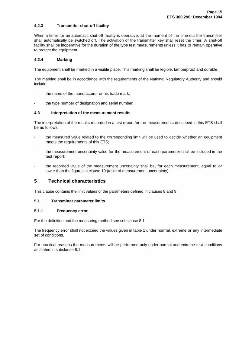
5.1.1 Frequency error
For the definition and the measuring method see subclause 8.1.
The frequency error shall not exceed the values given in table 1 under normal, extreme or any intermediateset of conditions.
For practical reasons the measurements will be performed only under normal and extreme test conditionsas stated in subclause 8.1.
Page 16ETS 300 296: December 1994
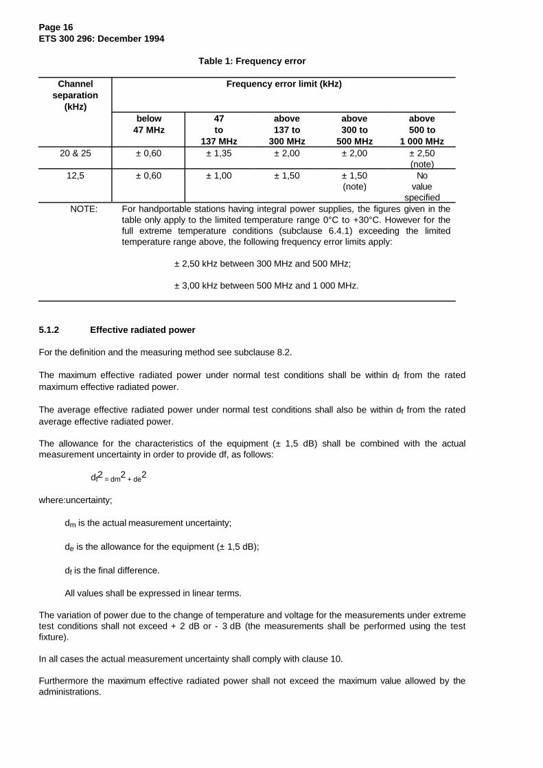
Table 1: Frequency error
Channelseparation
(kHz)
Frequency error limit (kHz)
below47 MHz
47to
137 MHz
above137 to
300 MHz
above300 to
500 MHz
above500 to
1 000 MHz20 & 25 ± 0,60 ± 1,35 ± 2,00 ± 2,00 ± 2,50
(note)12,5 ± 0,60 ± 1,00 ± 1,50 ± 1,50
(note)No
valuespecified
NOTE: For handportable stations having integral power supplies, the figures given in thetable only apply to the limited temperature range 0°C to +30°C. However for thefull extreme temperature conditions (subclause 6.4.1) exceeding the limitedtemperature range above, the following frequency error limits apply:
± 2,50 kHz between 300 MHz and 500 MHz;
± 3,00 kHz between 500 MHz and 1 000 MHz.
5.1.2 Effective radiated power
For the definition and the measuring method see subclause 8.2.
The maximum effective radiated power under normal test conditions shall be within df from the ratedmaximum effective radiated power.
The average effective radiated power under normal test conditions shall also be within df from the ratedaverage effective radiated power.
The allowance for the characteristics of the equipment (± 1,5 dB) shall be combined with the actualmeasurement uncertainty in order to provide df, as follows:
df2 = dm2 + de2
where:uncertainty;
dm is the actual measurement uncertainty;
de is the allowance for the equipment (± 1,5 dB);
df is the final difference.
All values shall be expressed in linear terms.
The variation of power due to the change of temperature and voltage for the measurements under extremetest conditions shall not exceed + 2 dB or - 3 dB (the measurements shall be performed using the testfixture).
In all cases the actual measurement uncertainty shall comply with clause 10.
Furthermore the maximum effective radiated power shall not exceed the maximum value allowed by theadministrations.
Page 17ETS 300 296: December 1994
Example of the calculation of df:
dm = 6 dB (value acceptable, as indicated in the table of maximum uncertainties)
= 3,98 in linear terms;
de = 1,5 dB (fixed value for all equipment fulfilling the requirements of this ETS);
= 1,41 in linear terms;
df2 = [3,98]2 + [1,41]2
Therefore df = 4,22 in linear terms, or 6,25 dB.
This calculation shows that in this case df is in excess of 0,25 dB compared to dm, the actualmeasurement uncertainty (6 dB).
5.1.3 Frequency deviation
For the definition and the measuring method see subclause 8.3.
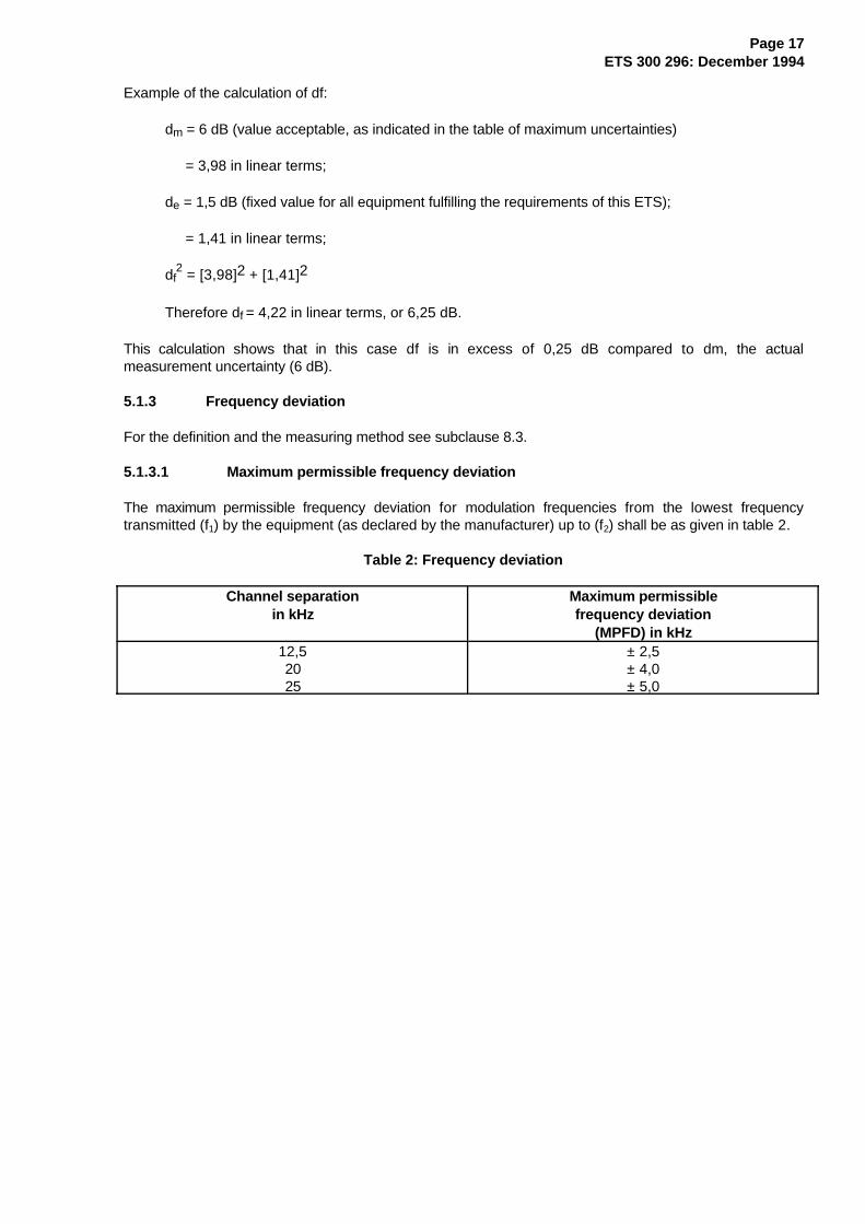
5.1.3.1 Maximum per missible frequency deviation
The maximum permissible frequency deviation for modulation frequencies from the lowest frequencytransmitted (f1) by the equipment (as declared by the manufacturer) up to (f2) shall be as given in table 2.
Table 2: Frequency deviation
Channel separationin kHz
Maximum permissiblefrequency deviation
(MPFD) in kHz12,52025
± 2,5± 4,0± 5,0
Page 18ETS 300 296: December 1994
MPFD
A
30%MPFD
f f 6 kHz f1 2 cs
Frequency deviation Audio frequency
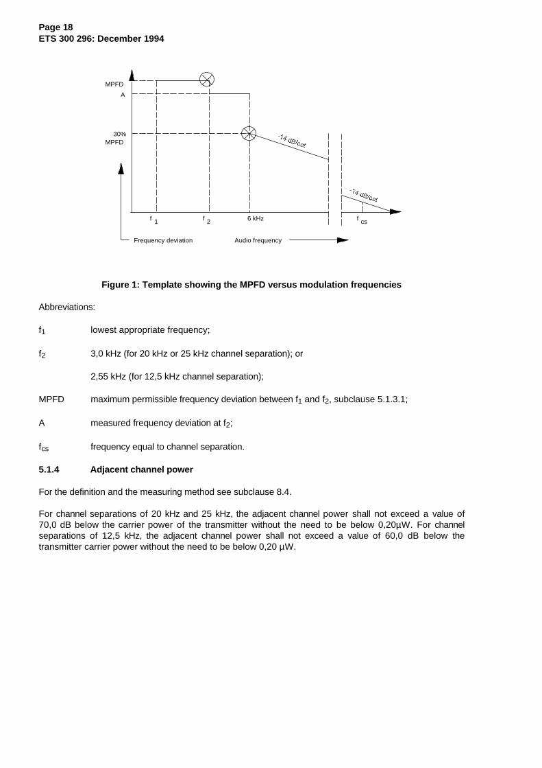
Figure 1: Template showing the MPFD versus modulation frequencies
Abbreviations:
f1 lowest appropriate frequency;
f2 3,0 kHz (for 20 kHz or 25 kHz channel separation); or
2,55 kHz (for 12,5 kHz channel separation);
MPFD maximum permissible frequency deviation between f1 and f2, subclause 5.1.3.1;
A measured frequency deviation at f2;
fcs frequency equal to channel separation.
5.1.4 Adjacent channel power
For the definition and the measuring method see subclause 8.4.
For channel separations of 20 kHz and 25 kHz, the adjacent channel power shall not exceed a value of70,0 dB below the carrier power of the transmitter without the need to be below 0,20µW. For channelseparations of 12,5 kHz, the adjacent channel power shall not exceed a value of 60,0 dB below thetransmitter carrier power without the need to be below 0,20 µW.
Page 19ETS 300 296: December 1994
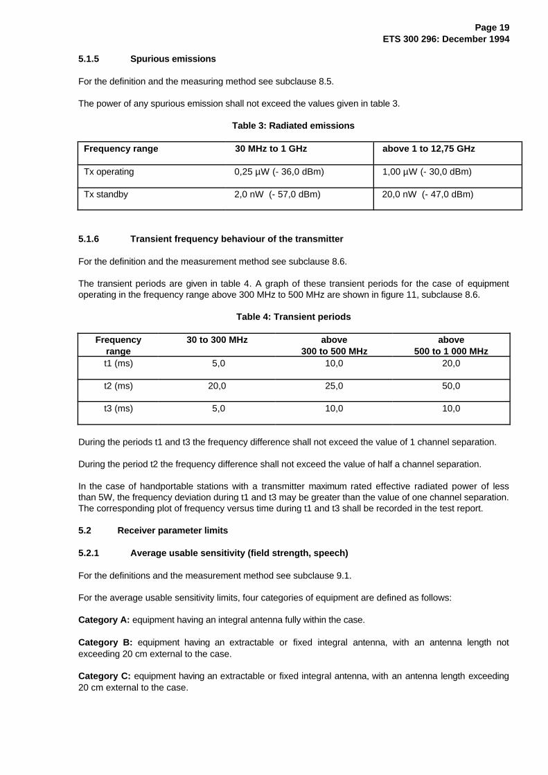
5.1.5 Spurious emissions
For the definition and the measuring method see subclause 8.5.
The power of any spurious emission shall not exceed the values given in table 3.
Table 3: Radiated emissions
Frequency range 30 MHz to 1 GHz above 1 to 12,75 GHz
Tx operating 0,25 µW (- 36,0 dBm) 1,00 µW (- 30,0 dBm)
Tx standby 2,0 nW (- 57,0 dBm) 20,0 nW (- 47,0 dBm)
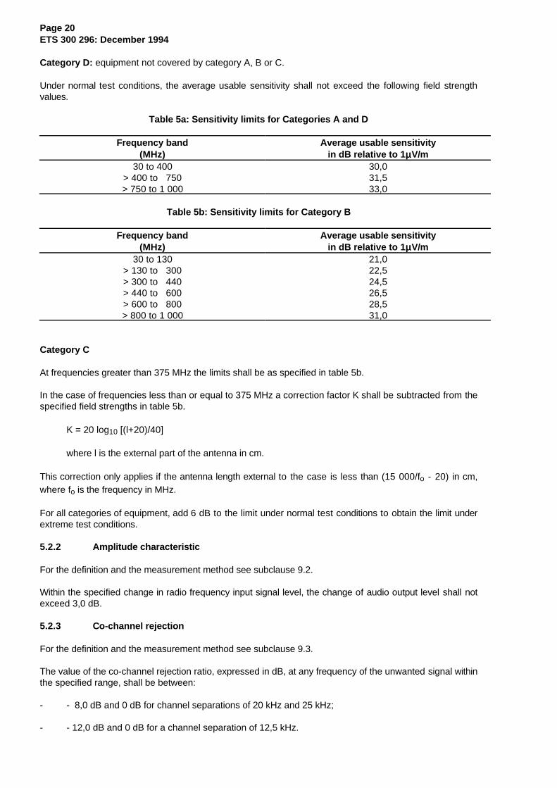
5.1.6 Transient frequency behaviour of the transmitter
For the definition and the measurement method see subclause 8.6.
The transient periods are given in table 4. A graph of these transient periods for the case of equipmentoperating in the frequency range above 300 MHz to 500 MHz are shown in figure 11, subclause 8.6.
Table 4: Transient periods
Frequencyrange
30 to 300 MHz above300 to 500 MHz
above500 to 1 000 MHz
t1 (ms) 5,0 10,0 20,0
t2 (ms) 20,0 25,0 50,0
t3 (ms) 5,0 10,0 10,0
During the periods t1 and t3 the frequency difference shall not exceed the value of 1 channel separation.
During the period t2 the frequency difference shall not exceed the value of half a channel separation.
In the case of handportable stations with a transmitter maximum rated effective radiated power of lessthan 5W, the frequency deviation during t1 and t3 may be greater than the value of one channel separation.The corresponding plot of frequency versus time during t1 and t3 shall be recorded in the test report.
5.2 Receiver parameter limits
5.2.1 Average usable sensitivity (field strength, speech)
For the definitions and the measurement method see subclause 9.1.
For the average usable sensitivity limits, four categories of equipment are defined as follows:
Category A: equipment having an integral antenna fully within the case.
Category B: equipment having an extractable or fixed integral antenna, with an antenna length notexceeding 20 cm external to the case.
Category C: equipment having an extractable or fixed integral antenna, with an antenna length exceeding20 cm external to the case.
Page 20ETS 300 296: December 1994
Category D: equipment not covered by category A, B or C.
Under normal test conditions, the average usable sensitivity shall not exceed the following field strengthvalues.
Table 5a: Sensitivity limits for Categories A and D
Frequency band(MHz)
Average usable sensitivityin dB relative to 1 µµV/m
30 to 400> 400 to 750> 750 to 1 000
30,031,533,0
Table 5b: Sensitivity limits for Category B
Frequency band(MHz)
Average usable sensitivityin dB relative to 1 µµV/m
30 to 130> 130 to 300> 300 to 440> 440 to 600> 600 to 800> 800 to 1 000
21,022,524,526,528,531,0
Category C
At frequencies greater than 375 MHz the limits shall be as specified in table 5b.
In the case of frequencies less than or equal to 375 MHz a correction factor K shall be subtracted from thespecified field strengths in table 5b.
K = 20 log10 [(l+20)/40]
where l is the external part of the antenna in cm.
This correction only applies if the antenna length external to the case is less than (15 000/fo - 20) in cm,where fo is the frequency in MHz.
For all categories of equipment, add 6 dB to the limit under normal test conditions to obtain the limit underextreme test conditions.
5.2.2 Amplitude characteristic
For the definition and the measurement method see subclause 9.2.
Within the specified change in radio frequency input signal level, the change of audio output level shall notexceed 3,0 dB.
5.2.3 Co-channel rejection
For the definition and the measurement method see subclause 9.3.
The value of the co-channel rejection ratio, expressed in dB, at any frequency of the unwanted signal withinthe specified range, shall be between:
- - 8,0 dB and 0 dB for channel separations of 20 kHz and 25 kHz;
- - 12,0 dB and 0 dB for a channel separation of 12,5 kHz.
Page 21ETS 300 296: December 1994
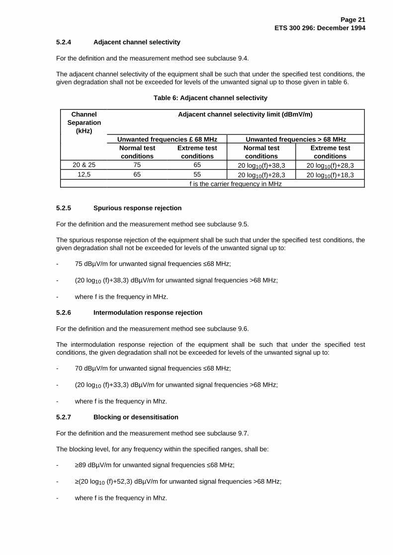
5.2.4 Adjacent channel selectivity
For the definition and the measurement method see subclause 9.4.
The adjacent channel selectivity of the equipment shall be such that under the specified test conditions, thegiven degradation shall not be exceeded for levels of the unwanted signal up to those given in table 6.
Table 6: Adjacent channel selectivity
ChannelSeparation
(kHz)
Adjacent channel selectivity limit (dBmV/m)
Unwanted frequencies £ 68 MHz Unwanted frequencies > 68 MHzNormal testconditions
Extreme testconditions
Normal testconditions
Extreme testconditions
20 & 25 75 65 20 log10(f)+38,3 20 log10(f)+28,312,5 65 55 20 log10(f)+28,3 20 log10(f)+18,3
f is the carrier frequency in MHz
5.2.5 Spurious response rejection
For the definition and the measurement method see subclause 9.5.
The spurious response rejection of the equipment shall be such that under the specified test conditions, thegiven degradation shall not be exceeded for levels of the unwanted signal up to:
- 75 dBµV/m for unwanted signal frequencies ≤68 MHz;
- (20 log10 (f)+38,3) dBµV/m for unwanted signal frequencies >68 MHz;
- where f is the frequency in MHz.
5.2.6 Intermodulation response rejection
For the definition and the measurement method see subclause 9.6.
The intermodulation response rejection of the equipment shall be such that under the specified testconditions, the given degradation shall not be exceeded for levels of the unwanted signal up to:
- 70 dBµV/m for unwanted signal frequencies ≤68 MHz;
- (20 log10 (f)+33,3) dBµV/m for unwanted signal frequencies >68 MHz;
- where f is the frequency in Mhz.
5.2.7 Blocking or desensitisation
For the definition and the measurement method see subclause 9.7.
The blocking level, for any frequency within the specified ranges, shall be:
- ≥89 dBµV/m for unwanted signal frequencies ≤68 MHz;
- ≥(20 log10 (f)+52,3) dBµV/m for unwanted signal frequencies >68 MHz;
- where f is the frequency in Mhz.
Page 22ETS 300 296: December 1994
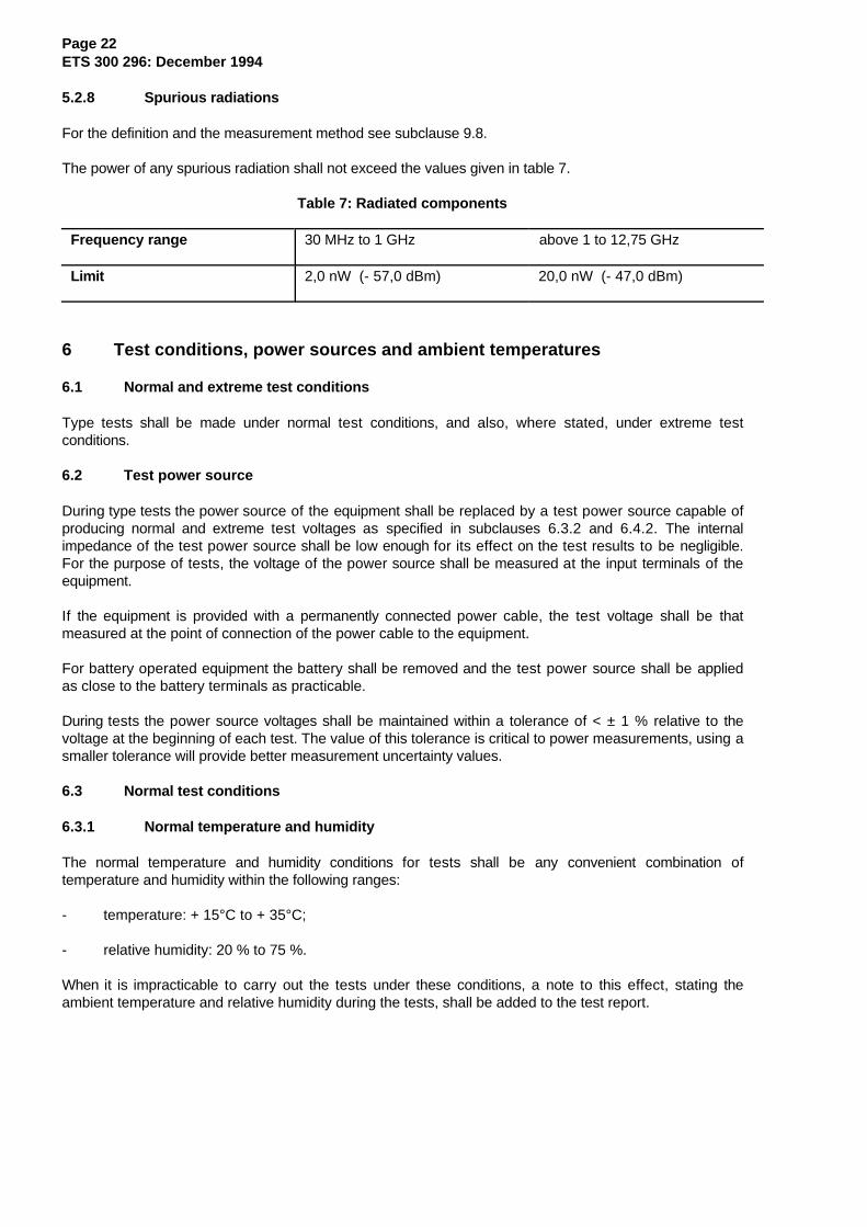
5.2.8 Spurious radiations
For the definition and the measurement method see subclause 9.8.
The power of any spurious radiation shall not exceed the values given in table 7.
Table 7: Radiated components
Frequency range 30 MHz to 1 GHz above 1 to 12,75 GHz
Limit 2,0 nW (- 57,0 dBm) 20,0 nW (- 47,0 dBm)
6 Test conditions, power sources and ambient temperatures
6.1 Normal and extreme test conditions
Type tests shall be made under normal test conditions, and also, where stated, under extreme testconditions.
6.2 Test power source
During type tests the power source of the equipment shall be replaced by a test power source capable ofproducing normal and extreme test voltages as specified in subclauses 6.3.2 and 6.4.2. The internalimpedance of the test power source shall be low enough for its effect on the test results to be negligible.For the purpose of tests, the voltage of the power source shall be measured at the input terminals of theequipment.
If the equipment is provided with a permanently connected power cable, the test voltage shall be thatmeasured at the point of connection of the power cable to the equipment.
For battery operated equipment the battery shall be removed and the test power source shall be appliedas close to the battery terminals as practicable.
During tests the power source voltages shall be maintained within a tolerance of < ± 1 % relative to thevoltage at the beginning of each test. The value of this tolerance is critical to power measurements, using asmaller tolerance will provide better measurement uncertainty values.
6.3 Normal test conditions
6.3.1 Normal temperature and humidity
The normal temperature and humidity conditions for tests shall be any convenient combination oftemperature and humidity within the following ranges:
- temperature: + 15°C to + 35°C;
- relative humidity: 20 % to 75 %.
When it is impracticable to carry out the tests under these conditions, a note to this effect, stating theambient temperature and relative humidity during the tests, shall be added to the test report.
Page 23ETS 300 296: December 1994
6.3.2 Normal test power source
6.3.2.1 Mains voltage
The normal test voltage for equipment to be connected to the mains shall be the nominal mains voltage.For the purpose of this ETS, the nominal voltage shall be the declared voltage or any of the declaredvoltages for which the equipment was designed.
The frequency of the test power source corresponding to the ac mains shall be between 49 and 51 Hz.
6.3.2.2 Regulated lead-acid battery power sources used on vehicles
When the radio equipment is intended for operation from the usual types of regulated lead-acid batterypower source used on vehicles, the normal test voltage shall be 1,1 times the nominal voltage of thebattery. For nominal voltages of 6V and 12V, these are 6,6V and 13,2V respectively.
6.3.2.3 Other power sources
For operation from other power sources or types of battery (primary or secondary), the normal testvoltage shall be that declared by the equipment manufacturer.
6.4 Extreme test conditions
6.4.1 Extreme temperatures
For tests at extreme temperatures, measurements shall be made in accordance with the proceduresspecified in subclause 6.5, at the upper and lower temperatures of the following range:
- 20°C to +55°C.
For the purpose of subclause 5.1.1 a) an additional extreme temperature range of 0°C to +30°C shall beused.
Type test reports shall state the temperature range used.
6.4.2 Extreme test source voltages
6.4.2.1 Mains voltage
The extreme test voltage for equipment to be connected to an ac mains source shall be the nominal mainsvoltage ± 10 %.
6.4.2.2 Regulated lead-acid battery power sources used on vehicles
When the equipment is intended for operation from the usual types of regulated lead-acid battery powersources used on vehicles the extreme test voltages shall be 1,3 and 0,9 times the nominal voltage of thebattery. For a nominal voltage of 6V, these are 7,8V and 5,4V respectively and for a nominal voltage of12V, these are 15,6V and 10,8V respectively.
6.4.2.3 Power sources using other types of batteries
The lower extreme test voltages for equipment with power sources using the following batteries shall be:
- for the Leclanché or the lithium type of battery: 0,85 times the nominal voltage of the battery;
- for the mercury or nickel-cadmium type of battery: 0,9 times the nominal voltage of the battery.
No upper extreme test voltages apply.
Page 24ETS 300 296: December 1994
6.4.2.4 Other power sources
For equipment using other power sources, or capable of being operated from a variety of power sources,the extreme test voltages shall be those agreed between the equipment manufacturer and the testinglaboratory and shall be recorded in the test report.
6.5 Procedure for tests at extreme temperatures
Before measurements are made the equipment shall have reached thermal balance in the test chamber.The equipment shall be switched off during the temperature stabilising period.
In the case of equipment containing temperature stabilisation circuits designed to operate continuously, thetemperature stabilisation circuits may be switched on for 15 minutes after thermal balance has beenobtained, and the equipment shall then meet the specified requirements. For such equipment themanufacturer shall provide for the power source circuit feeding the crystal oven to be independent of thepower source to the rest of the equipment.
If the thermal balance is not checked by measurements, a temperature stabilising period of at least onehour, or such period as may be decided by the testing laboratory, shall be allowed. The sequence ofmeasurements shall be chosen, and the humidity content in the test chamber shall be controlled so thatexcessive condensation does not occur.
6.5.1 Procedure for equipment designed for continuous operation
If the manufacturer states that the equipment is designed for continuous operation, the test procedure shallbe as follows.
Before tests at the upper extreme temperature the equipment shall be placed in the test chamber and leftuntil thermal balance is attained. The equipment shall then be switched on in the transmit conditions for aperiod of half an hour after which the equipment shall meet the specified requirements.
For tests at the lower extreme temperature the equipment shall be left in the test chamber until thermalbalance is attained, then switched to the standby or receive condition for a period of one minute afterwhich the equipment shall meet the specified requirements.
6.5.2 Procedure for equipment designed for intermittent operation
If the manufacturer states that the equipment is designed for intermittent operation, the test procedureshall be as follows.
Before tests at the upper extreme temperature the equipment shall be placed in the test chamber and leftuntil thermal balance is attained. The equipment shall then be switched on for one minute in the transmitcondition, followed by four minutes in the receive condition, after which the equipment shall meet thespecified requirements.
For tests at the lower extreme temperature the equipment shall be left in the test chamber until thermalbalance is attained, then switched to the standby or receive condition for one minute after which theequipment shall meet the specified requirements.
Page 25ETS 300 296: December 1994
7 General conditions
7.1 Test modulation
The test modulation signals are baseband signals that modulate a carrier or signal generator. They aredependent upon the type of equipment under test and also the measurement to be performed.
Test modulating signals are:
A-M1: a 1 000 Hz tone at a level which produces a deviation of 12 % of the channel separation;
A-M2: a 1 250 Hz tone at a level which produces a deviation of 12 % of the channel separation;
A-M3: a 400 Hz tone at a level which produces a deviation of 12 % of the channel separation. This signal is used as an unwanted signal.
7.2 Artificial antenna
Tests on the transmitter requiring the use of the test fixture shall be carried out with a substantiallynon-reactive non-radiating load of 50 Ω connected to the test fixture terminal.
7.3 Test sites and general arrangements for radiated measurements
For guidance on radiation test sites see annex A. Detailed descriptions of the radiated measurementarrangements are included in this annex.
7.4 Transmitter automatic shut-off facility
If the equipment is fitted with an automatic transmitter shut-off facility it shall be made inoperative for theduration of the type test unless it has to be left operative to protect the equipment. If the shut off facility isleft operative the status of the equipment shall be indicated.
7.5 Arrangement for test signals at the input of the transmitter
For the purpose of this ETS, the transmitter audio frequency modulation signal shall be applied to themicrophone input terminals with the internal microphone disconnected, unless otherwise stated.
7.6 Arrangements for test signals at the input of the receiver via a test fixture or a testantenna
Sources of test signals for application to the receiver via a test fixture (annex A, clause A.6), a stripline(annex A, subclause A.1.3) or a test antenna (annex A, clause A.4) shall be connected in such a way thatthe impedance presented to the test fixture, the stripline or the test antenna is 50 Ω. This requirement shallbe met irrespective whether one or more signals using a combining network are applied to the receiversimultaneously.
The levels of the test signals shall be expressed in terms of the emf at the output of the source prior toconnection to the receiver input connector.
The effects of any intermodulation products and noise produced in the test signal sources shall benegligible.
7.7 Receiver mute or squelch facility
If the receiver is equipped with a mute or squelch circuit, this shall be made inoperative for the duration ofthe type tests.
Page 26ETS 300 296: December 1994
7.8 Receiver rated audio output power
The rated audio output power shall be the maximum power, declared by the manufacturer, for which all therequirements of this ETS are met. With normal test modulation, subclause 7.1, the audio output powershall be measured in a resistive load simulating the load with which the receiver normally operates. Thevalue of this load shall be declared by the manufacturer.
8 Methods of measurement for transmitter parameters
When performing transmitter tests on equipment designed for intermittent operation, the specifiedmaximum transmit time shall not be exceeded.
8.1 Frequency error
8.1.1 Definition
The frequency error of the transmitter is the difference between the measured carrier frequency in theabsence of modulation and the nominal frequency of the transmitter.
8.1.2 Method of measurement
ÚÄÄÄÄÄÄÄÄÄÄÄÄÄÄÄÄÄÄÄÄÄÄ¿³ ³³ ÚÄÄÄÄÄÄÄÄÄÄÄÄÄÄÄÄ¿ ³ ÚÄÄÄÄÄÄÄÄÄÄÄÄÄÄÄ¿ ÚÄÄÄÄÄÄÄÄÄÄÄÄÄÄÄ¿³ ³ ³ ³ ³ ³ ³ ³³ ³ Transmitter ³ ³ ³ Artificial ³ ³ Frequency ³³ ³ under ³ ÃÄÄÄÄÄÄ>´ Antenna ÃÄÄÄÄÄÄ>´ Meter ³³ ³ test ³ ³ ³ ³ ³ ³³ ³ ³ ³ ³ ³ ³ ³³ ÀÄÄÄÄÄÄÄÄÄÄÄÄÄÄÄÄÙ ³ ÀÄÄÄÄÄÄÄÄÄÄÄÄÄÄÄÙ ÀÄÄÄÄÄÄÄÄÄÄÄÄÄÄÄÙ³ ³³ Test Fixture ³ÀÄÄÄÄÄÄÄÄÄÄÄÄÄÄÄÄÄÄÄÄÄÄÙ
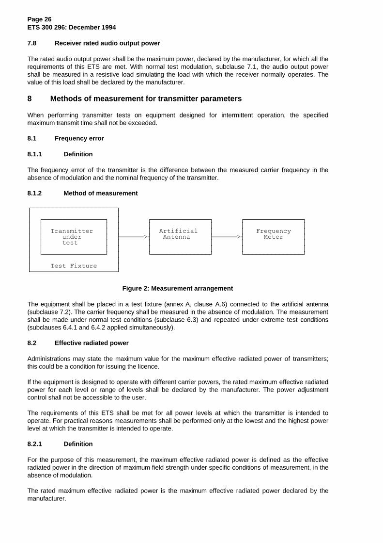
Figure 2: Measurement arrangement
The equipment shall be placed in a test fixture (annex A, clause A.6) connected to the artificial antenna(subclause 7.2). The carrier frequency shall be measured in the absence of modulation. The measurementshall be made under normal test conditions (subclause 6.3) and repeated under extreme test conditions(subclauses 6.4.1 and 6.4.2 applied simultaneously).
8.2 Effective radiated power
Administrations may state the maximum value for the maximum effective radiated power of transmitters;this could be a condition for issuing the licence.
If the equipment is designed to operate with different carrier powers, the rated maximum effective radiatedpower for each level or range of levels shall be declared by the manufacturer. The power adjustmentcontrol shall not be accessible to the user.
The requirements of this ETS shall be met for all power levels at which the transmitter is intended tooperate. For practical reasons measurements shall be performed only at the lowest and the highest powerlevel at which the transmitter is intended to operate.
8.2.1 Definition
For the purpose of this measurement, the maximum effective radiated power is defined as the effectiveradiated power in the direction of maximum field strength under specific conditions of measurement, in theabsence of modulation.
The rated maximum effective radiated power is the maximum effective radiated power declared by themanufacturer.
Page 27ETS 300 296: December 1994
The average effective radiated power is defined as the average of the effective radiated power measuredin 8 directions.
The rated average effective radiated power shall also be declared by the manufacturer.
8.2.2 Method of measurement
The measurements shall be made under normal test conditions, subclause 6.3, and extreme testconditions, subclauses 6.4.1 and 6.4.2 applied simultaneously.
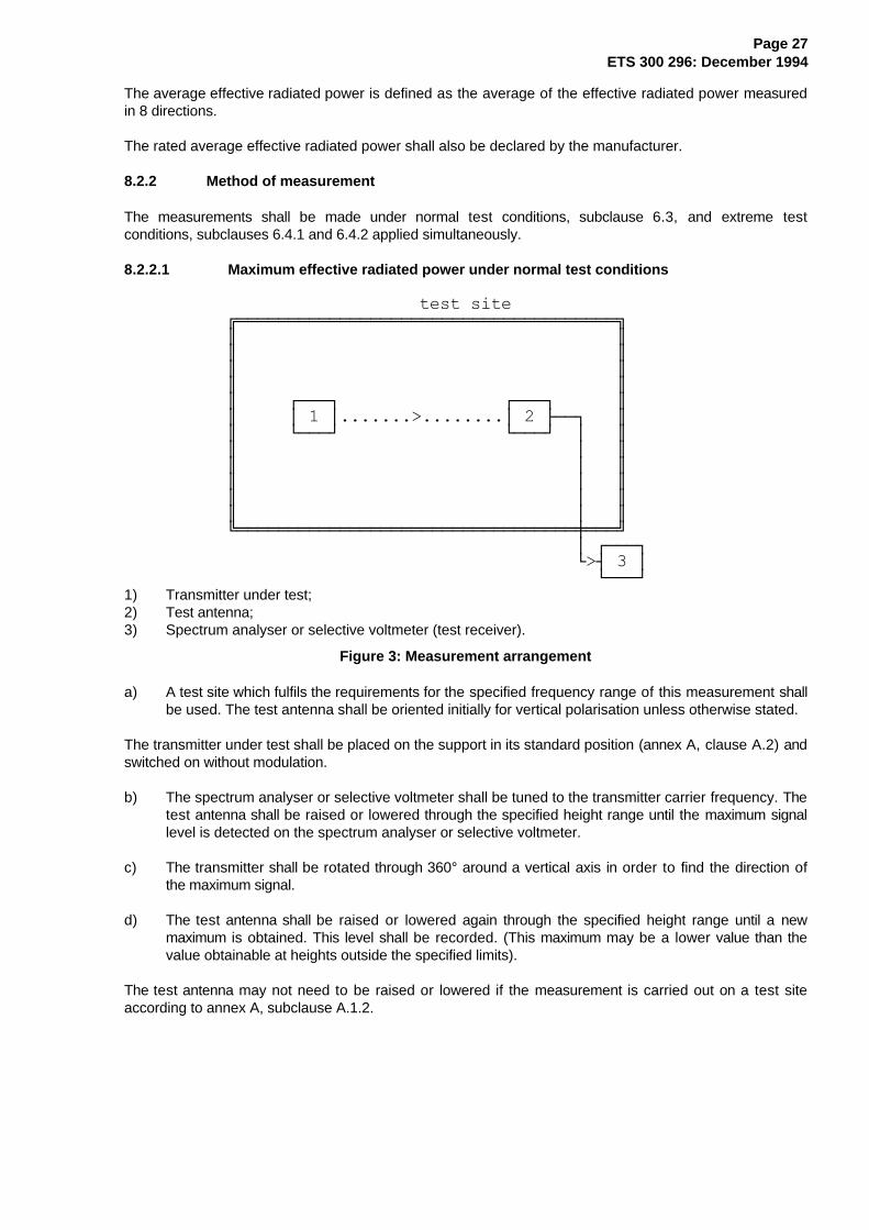
8.2.2.1 Maximum effective radiated power under normal test conditions
test site ÉÍÍÍÍÍÍÍÍÍÍÍÍÍÍÍÍÍÍÍÍÍÍÍÍÍÍÍÍÍÍÍÍÍÍÍÍÍ» º º º º º º º º º ÚÄÄÄ¿ ÚÄÄÄ¿ º º ³ 1 ³.......>........³ 2 ÃÄÄ¿ º º ÀÄÄÄÙ ÀÄÄÄÙ ³ º º ³ º º ³ º º ³ º º ³ º º ³ º ÈÍÍÍÍÍÍÍÍÍÍÍÍÍÍÍÍÍÍÍÍÍÍÍÍÍÍÍÍÍÍÍÍÍØÍÍͼ ³ ÚÄÄÄ¿ À>´ 3 ³ ÀÄÄÄÙ1) Transmitter under test;2) Test antenna;3) Spectrum analyser or selective voltmeter (test receiver).
Figure 3: Measurement arrangement
a) A test site which fulfils the requirements for the specified frequency range of this measurement shallbe used. The test antenna shall be oriented initially for vertical polarisation unless otherwise stated.
The transmitter under test shall be placed on the support in its standard position (annex A, clause A.2) andswitched on without modulation.
b) The spectrum analyser or selective voltmeter shall be tuned to the transmitter carrier frequency. Thetest antenna shall be raised or lowered through the specified height range until the maximum signallevel is detected on the spectrum analyser or selective voltmeter.
c) The transmitter shall be rotated through 360° around a vertical axis in order to find the direction ofthe maximum signal.
d) The test antenna shall be raised or lowered again through the specified height range until a newmaximum is obtained. This level shall be recorded. (This maximum may be a lower value than thevalue obtainable at heights outside the specified limits).
The test antenna may not need to be raised or lowered if the measurement is carried out on a test siteaccording to annex A, subclause A.1.2.
Page 28ETS 300 296: December 1994
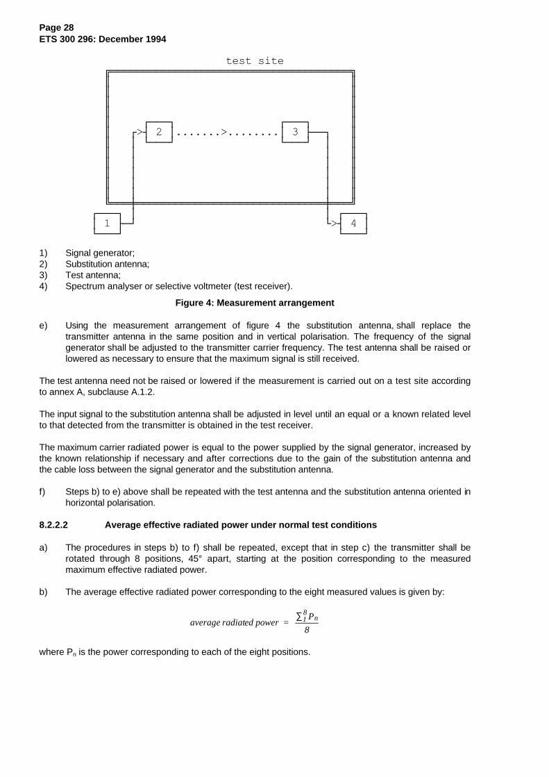
test site ÉÍÍÍÍÍÍÍÍÍÍÍÍÍÍÍÍÍÍÍÍÍÍÍÍÍÍÍÍÍÍÍÍÍÍÍÍÍ» º º º º º º º º º ÚÄÄÄ¿ ÚÄÄÄ¿ º º Ú>´ 2 ³.......>........³ 3 ÃÄÄ¿ º º ³ ÀÄÄÄÙ ÀÄÄÄÙ ³ º º ³ ³ º º ³ ³ º º ³ ³ º º ³ ³ º º ³ ³ º ÈÍÍÍØÍÍÍÍÍÍÍÍÍÍÍÍÍÍÍÍÍÍÍÍÍÍÍÍÍÍÍÍÍØÍÍͼ ÚÄÄÄ¿ ³ ³ ÚÄÄÄ¿ ³ 1 ÃÄÙ À>´ 4 ³ ÀÄÄÄÙ ÀÄÄÄÙ
1) Signal generator;2) Substitution antenna;3) Test antenna;4) Spectrum analyser or selective voltmeter (test receiver).
Figure 4: Measurement arrangement
e) Using the measurement arrangement of figure 4 the substitution antenna, shall replace thetransmitter antenna in the same position and in vertical polarisation. The frequency of the signalgenerator shall be adjusted to the transmitter carrier frequency. The test antenna shall be raised orlowered as necessary to ensure that the maximum signal is still received.
The test antenna need not be raised or lowered if the measurement is carried out on a test site accordingto annex A, subclause A.1.2.
The input signal to the substitution antenna shall be adjusted in level until an equal or a known related levelto that detected from the transmitter is obtained in the test receiver.
The maximum carrier radiated power is equal to the power supplied by the signal generator, increased bythe known relationship if necessary and after corrections due to the gain of the substitution antenna andthe cable loss between the signal generator and the substitution antenna.
f) Steps b) to e) above shall be repeated with the test antenna and the substitution antenna oriented inhorizontal polarisation.
8.2.2.2 Average effective radiated power under normal test conditions
a) The procedures in steps b) to f) shall be repeated, except that in step c) the transmitter shall berotated through 8 positions, 45° apart, starting at the position corresponding to the measuredmaximum effective radiated power.
b) The average effective radiated power corresponding to the eight measured values is given by:
average radiated power = P
818
n∑
where Pn is the power corresponding to each of the eight positions.

Page 29ETS 300 296: December 1994
8.2.3 Method of measurements of maximum and average effective radiated power underextreme test conditions
ÚÄÄÄÄÄÄÄÄÄÄÄÄÄÄÄ¿ ³ ÚÄÄÄÄÄÄÄÄÄÄÄ¿ ³ ÚÄÄÄÄÄÄÄÄ¿ ÚÄÄÄÄÄÄÄÄÄÄÄÄ¿ ³ ³Transmitter³ ³ ³ Test ³ ³ RF power ³ ³ ³ under ³ ÃÄÄÄ>´ ÃÄÄ>´ ³ ³ ³ test ³ ³ ³ load ³ ³ meter ³ ³ ÀÄÄÄÄÄÄÄÄÄÄÄÙ ³ ÀÄÄÄÄÄÄÄÄÙ ÀÄÄÄÄÄÄÄÄÄÄÄÄÙ ³ Test fixture ³ ÀÄÄÄÄÄÄÄÄÄÄÄÄÄÄÄÙ
Figure 5: Measurement arrangement
a) The measurement specified in subclause 8.2.2 shall also be performed under extreme testconditions. Due to the impossibility of repeating the measurement on a test site under extremetemperature conditions, a relative measurement is performed, using the test fixture (annex A,clause A.6) and the measurement arrangement of figure 5.
b) The power delivered to the test load is measured under normal test conditions (subclause 6.3) andextreme test conditions (subclauses 6.4.1 and 6.4.2 applied simultaneously), and the difference indB is noted. This difference is algebraically added to the average effective radiated power undernormal test conditions, in order to obtain the average effective radiated power under extreme testconditions.
c) A similar calculation will provide the maximum effective radiated power.
d) Additional uncertainties can occur under extreme test conditions due to the calibration of the testfixture.
8.3 Frequency deviation
The frequency deviation is the maximum difference between the instantaneous frequency of the modulatedradio frequency signal and the carrier frequency in the absence of modulation.
8.3.1 Maximum permissible frequency deviation
8.3.1.1 Definition
The maximum permissible frequency deviation is the maximum value of frequency deviation stated for therelevant channel separation.
Page 30ETS 300 296: December 1994
8.3.1.2 Method of measurement
ÚÄÄÄÄÄÄÄÄÄÄÄÄÄÄÄÄÄÄ¿³ ÚÄÄÄÄÄÄÄÄÄÄÄ¿ ³ ÚÄÄÄÄÄÄÄÄÄÄ¿ ÚÄÄÄÄÄÄÄÄÄÄÄÄÄ¿³ ³Transmitter³ ³ ³Artificial³ ³ Deviation ³³ ³ under ³ ÃÄÄÄÄÄÄÄ>´ ÃÄÄÄÄÄÄÄ>´ ³³ ³ test ³ ³ ³ antenna ³ ³ meter ³³ ÀÄÄÄÄÄÄÄÄÄÄÄÙ ³ ÀÄÄÄÄÄÄÄÄÄÄÙ ÀÄÄÄÄÄÄÄÄÄÄÄÄÄÙ³ Test Fixture ³ÀÄÄÄÄÄÄÄÄÄÂÄÄÄÄÄÄÄÄÙ ∧ ÚÄÄÄÄÄÁÄÄÄÄÄ¿ ³Modulating ³ ³ signal ³ ³ generator ³ ÀÄÄÄÄÄÄÄÄÄÄÄÙ
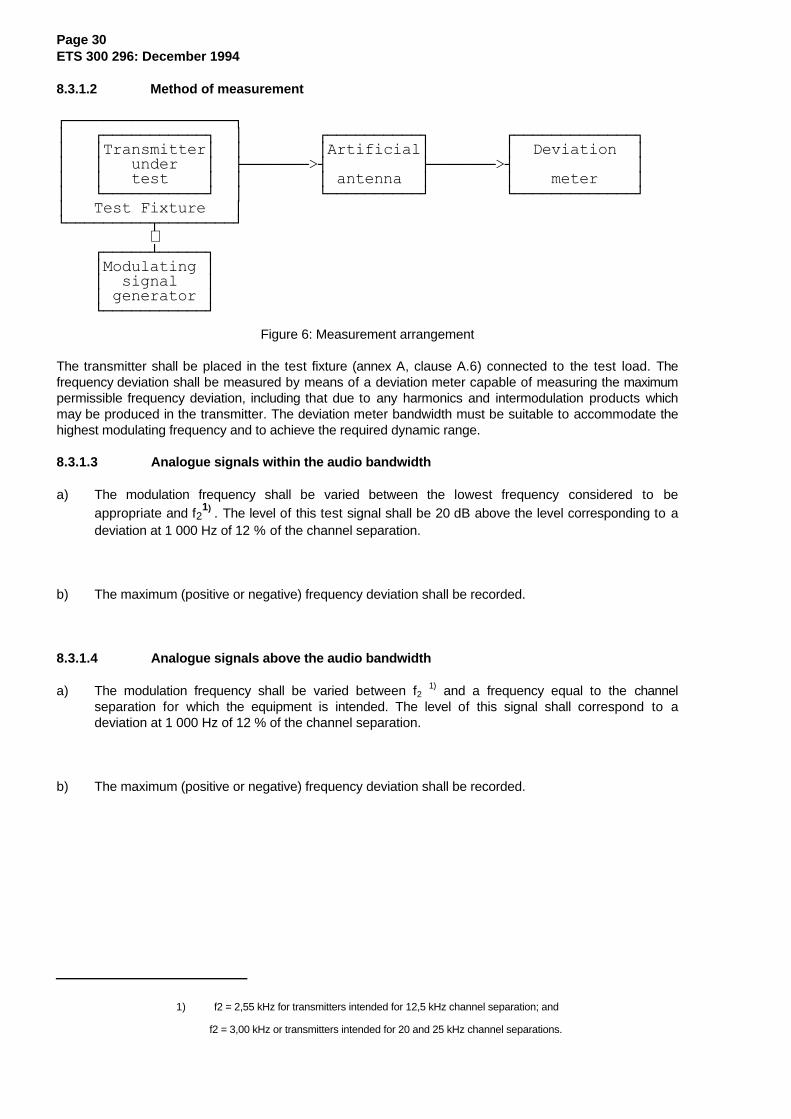
Figure 6: Measurement arrangement
The transmitter shall be placed in the test fixture (annex A, clause A.6) connected to the test load. Thefrequency deviation shall be measured by means of a deviation meter capable of measuring the maximumpermissible frequency deviation, including that due to any harmonics and intermodulation products whichmay be produced in the transmitter. The deviation meter bandwidth must be suitable to accommodate thehighest modulating frequency and to achieve the required dynamic range.
8.3.1.3 Analogue signals within the audio bandwidth
a) The modulation frequency shall be varied between the lowest frequency considered to beappropriate and f2
1) . The level of this test signal shall be 20 dB above the level corresponding to adeviation at 1 000 Hz of 12 % of the channel separation.
b) The maximum (positive or negative) frequency deviation shall be recorded.
8.3.1.4 Analogue signals above the audio bandwidth
a) The modulation frequency shall be varied between f2 1) and a frequency equal to the channel
separation for which the equipment is intended. The level of this signal shall correspond to adeviation at 1 000 Hz of 12 % of the channel separation.
b) The maximum (positive or negative) frequency deviation shall be recorded.
1) f2 = 2,55 kHz for transmitters intended for 12,5 kHz channel separation; and
f2 = 3,00 kHz or transmitters intended for 20 and 25 kHz channel separations.
Page 31ETS 300 296: December 1994
8.4 Adjacent channel power
8.4.1 Definition
The adjacent channel power is that part of the total power output of a transmitter under defined conditionsof modulation, which falls within a specified passband centred on the nominal frequency of either of theadjacent channels. This power is the sum of the mean power produced by the modulation, hum and noiseof the transmitter.
It is specified either as the ratio expressed in decibels of the carrier power to the adjacent channel poweror as an absolute value.
8.4.2 Method of measurement
The adjacent channel power may be measured with a power measuring receiver which conforms with therequirements given in annex B.
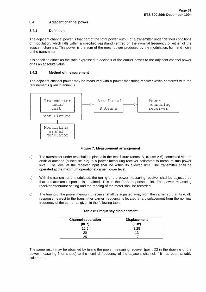
ÚÄÄÄÄÄÄÄÄÄÄÄÄÄÄÄÄÄÄÄÄ¿³ ÚÄÄÄÄÄÄÄÄÄÄÄÄÄ¿ ³ ÚÄÄÄÄÄÄÄÄÄÄÄ¿ ÚÄÄÄÄÄÄÄÄÄÄÄÄÄÄÄÄ¿³ ³ Transmitter ³ ³ ³ Artificial³ ³ Power ³³ ³ under ³ ÃÄÄÄ>´ ÃÄÄÄÄ>´ measuring ³³ ³ test ³ ³ ³ Antenna ³ ³ receiver ³³ ÀÄÄÄÄÄÄÄÄÄÄÄÄÄÙ ³ ÀÄÄÄÄÄÄÄÄÄÄÄÙ ÀÄÄÄÄÄÄÄÄÄÄÄÄÄÄÄÄÙ³ Test Fixture ³ÀÄÄÄÄÄÄÄÄÄÄÂÄÄÄÄÄÄÄÄÄÙ ÚÄÄÄÄÄÄÁÄÄÄÄÄÄ¿ ³ Modulating ³ ³ signal ³ ³ generator ³ ÀÄÄÄÄÄÄÄÄÄÄÄÄÄÙ
Figure 7: Measurement arrangement
a) The transmitter under test shall be placed in the test fixture (annex A, clause A.6) connected via theartificial antenna (subclause 7.2) to a power measuring receiver calibrated to measure rms powerlevel. The level at the receiver input shall be within its allowed limit. The transmitter shall beoperated at the maximum operational carrier power level.
b) With the transmitter unmodulated, the tuning of the power measuring receiver shall be adjusted sothat a maximum response is obtained. This is the 0 dB response point. The power measuringreceiver attenuator setting and the reading of the meter shall be recorded.
c) The tuning of the power measuring receiver shall be adjusted away from the carrier so that its -6 dBresponse nearest to the transmitter carrier frequency is located at a displacement from the nominalfrequency of the carrier as given in the following table.
Table 8: Frequency displacement
Channel separation(kHz)
Displacement(kHz)
12,52025
8,251317
The same result may be obtained by tuning the power measuring receiver (point D2 in the drawing of thepower measuring filter shape) to the nominal frequency of the adjacent channel, if it has been suitablycalibrated.
Page 32ETS 300 296: December 1994
d) The transmitter shall be modulated with a 1 250 Hz tone at a level which is 20 dB higher than thatrequired to produce normal deviation.
e) The power measuring receiver variable attenuator shall be adjusted to obtain the same meterreading as in step b) or a known relation to it. This value shall be recorded.
f) The ratio of adjacent channel power to carrier power is the difference between the attenuatorsettings in step b) and e), corrected for any differences in the reading of the meter. Alternatively theabsolute value of the adjacent channel power may be calculated from the above ratio and thetransmitter carrier power.
g) Steps c) to f) shall be repeated with the power measuring receiver tuned to the other side of thecarrier.
8.5 Radiated spurious emissions
8.5.1 Definition
Spurious emissions are emissions at frequencies, other than those of the carrier and sidebands associatedwith normal modulation, radiated by the antenna and by the cabinet of the transmitter.
They are specified as the radiated power of any discrete signal.
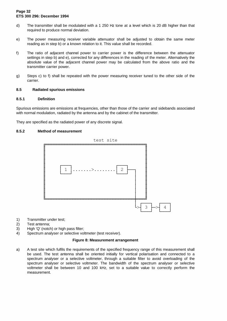
8.5.2 Method of measurement
test site ÉÍÍÍÍÍÍÍÍÍÍÍÍÍÍÍÍÍÍÍÍÍÍÍÍÍÍÍÍÍÍÍÍÍÍÍÍÍ» º º º º º º º º º ÚÄÄÄ¿ ÚÄÄÄ¿ º º ³ 1 ³.......>........³ 2 ÃÄÄ¿ º º ÀÄÄÄÙ ÀÄÄÄÙ ³ º º ³ º º ³ º º ³ º º ³ º º ³ º ÈÍÍÍÍÍÍÍÍÍÍÍÍÍÍÍÍÍÍÍÍÍÍÍÍÍÍÍÍÍÍÍÍÍØÍÍͼ ³ ÚÄÄÄ¿ ÚÄÄÄ¿ À>´ 3 ÃÄ>´ 4 ³ ÀÄÄÄÙ ÀÄÄÄÙ
1) Transmitter under test;2) Test antenna;3) High 'Q' (notch) or high pass filter;4) Spectrum analyser or selective voltmeter (test receiver).
Figure 8: Measurement arrangement
a) A test site which fulfils the requirements of the specified frequency range of this measurement shallbe used. The test antenna shall be oriented initially for vertical polarisation and connected to aspectrum analyser or a selective voltmeter, through a suitable filter to avoid overloading of thespectrum analyser or selective voltmeter. The bandwidth of the spectrum analyser or selectivevoltmeter shall be between 10 and 100 kHz, set to a suitable value to correctly perform themeasurement.
Page 33ETS 300 296: December 1994
For the measurement of spurious emissions below the second harmonic of the carrier frequency thefilter used shall be a high 'Q' (notch) filter centred on the transmitter carrier frequency andattenuating this signal by at least 30 dB.
For the measurement of spurious emissions at and above the second harmonic of the carrierfrequency the filter used shall be a high pass filter with a stop band rejection exceeding 40 dB. Thecut-off frequency of the high pass filter shall be approximately 1,5 times the transmitter carrierfrequency.
The transmitter under test shall be placed on the support in its standard position (annex A,clause A.2) and shall be switched on without modulation.
b) The radiation of any spurious emission shall be detected by the test antenna and spectrum analyseror selective voltmeter over the frequency range 30 MHz to 4 GHz, except for the channel on whichthe transmitter is intended to operate and its adjacent channels. In addition, for equipment operatingon frequencies above 470 MHz, measurements shall be repeated over the frequency range 4 GHzto 12,75 GHz. The frequency of each spurious emission detected shall be recorded. If the test siteis disturbed by interference coming from outside, this qualitative search may be performed in ascreened room, with a reduced distance between the transmitter and the test antenna.
c) At each frequency at which an emission has been detected, the spectrum analyser or selectivevoltmeter shall be tuned and the test antenna shall be raised or lowered through the specified heightrange until the maximum signal level is detected on the spectrum analyser or selective voltmeter.
d) The transmitter shall be rotated through 360° about a vertical axis, until a higher maximum signal isreceived.
e) The test antenna shall be raised or lowered again through the specified height range until a newmaximum is obtained. This level shall be recorded.
The test antenna may not need to be raised or lowered if the measurement is carried out on a testsite according to annex A, subclause A.1.2.
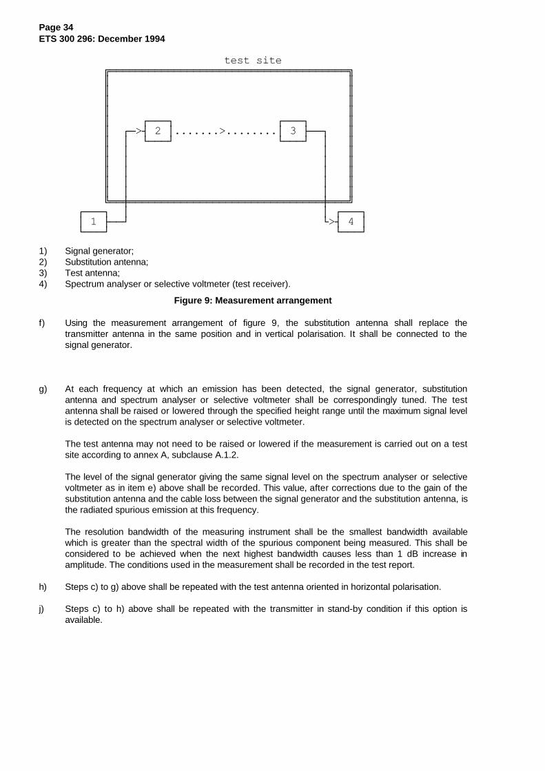
Page 34ETS 300 296: December 1994
test site ÉÍÍÍÍÍÍÍÍÍÍÍÍÍÍÍÍÍÍÍÍÍÍÍÍÍÍÍÍÍÍÍÍÍÍÍÍÍ» º º º º º º º º º ÚÄÄÄ¿ ÚÄÄÄ¿ º º ÚÄ>´ 2 ³.......>........³ 3 ÃÄÄ¿ º º ³ ÀÄÄÄÙ ÀÄÄÄÙ ³ º º ³ ³ º º ³ ³ º º ³ ³ º º ³ ³ º º ³ ³ º ÈÍÍØÍÍÍÍÍÍÍÍÍÍÍÍÍÍÍÍÍÍÍÍÍÍÍÍÍÍÍÍÍÍØÍÍͼ ÚÄÄÄ¿ ³ ³ ÚÄÄÄ¿ ³ 1 ÃÄÄÙ À>´ 4 ³ ÀÄÄÄÙ ÀÄÄÄÙ
1) Signal generator;2) Substitution antenna;3) Test antenna;4) Spectrum analyser or selective voltmeter (test receiver).
Figure 9: Measurement arrangement
f) Using the measurement arrangement of figure 9, the substitution antenna shall replace thetransmitter antenna in the same position and in vertical polarisation. It shall be connected to thesignal generator.
g) At each frequency at which an emission has been detected, the signal generator, substitutionantenna and spectrum analyser or selective voltmeter shall be correspondingly tuned. The testantenna shall be raised or lowered through the specified height range until the maximum signal levelis detected on the spectrum analyser or selective voltmeter.
The test antenna may not need to be raised or lowered if the measurement is carried out on a testsite according to annex A, subclause A.1.2.
The level of the signal generator giving the same signal level on the spectrum analyser or selectivevoltmeter as in item e) above shall be recorded. This value, after corrections due to the gain of thesubstitution antenna and the cable loss between the signal generator and the substitution antenna, isthe radiated spurious emission at this frequency.
The resolution bandwidth of the measuring instrument shall be the smallest bandwidth availablewhich is greater than the spectral width of the spurious component being measured. This shall beconsidered to be achieved when the next highest bandwidth causes less than 1 dB increase inamplitude. The conditions used in the measurement shall be recorded in the test report.
h) Steps c) to g) above shall be repeated with the test antenna oriented in horizontal polarisation.
j) Steps c) to h) above shall be repeated with the transmitter in stand-by condition if this option isavailable.
Page 35ETS 300 296: December 1994
8.6 Transient frequency behaviour of the transmitter
8.6.1 Definitions
Transient frequency behaviour of the transmitter: the variation in time of the transmitter frequencydifference from the nominal frequency of the transmitter when the RF output power is switched on and off.
ton : according to the method of measurement described in subclause 8.6.2 the switch-on instant ton of atransmitter is defined by the condition when the output power, measured at the antenna terminal,exceeds 0,1 % of the full output power (- 30 dBc).
t1: period of time starting at ton and finishing according to table 4, subclause 5.1.6.
t2: period of time starting at the end of t1 and finishing according to table 4, subclause 5.1.6.
toff : switch-off instant defined by the condition when the output power falls below 0,1 % of the full outputpower (- 30 dBc).
t3: period of time that finishing at toff and starting according to table 4, subclause 5.1.6.
8.6.2 Method of measurement
ÚÄÄÄÄÄÄÄÄÄÄÄÄÄÄÄ¿ 50 W power attenuator³ÚÄÄÄÄÄÄÄÄÄÄÄÄÄ¿³ ³ ÚÄÄÄÄ¿ ÚÄÄÄÄÄÄÄÄÄÄÄÄÄÄÄÄ¿ ÚÄÄÄÄÄÄÄÄÄ¿³³ ³³ ÚÅÄÄÄÄÄ¿ ³ ³ ³ ³ (ad) ³Ú¿ ³³³ Transmitter ³ÃÄ>´³ ÃÄ>´ ÃÄ>´ Test ÃÄÄÄÄÄ>´ÃÅÅÅÅÅÅ´ ³³ÀÄÄÄÄÄÄÄÄÄÄÄÄÄÙ³ ÀÄÄÄÄÄÄÙ ³ ³ ³ Discriminator ³ ³ÀÁÁÁÁÁÁÙ ³³ Test Fixture ³ ³ ³ ³ ÃÄÄÄÄÄ>´ Storage ³ÀÄÄÄÄÄÄÄÄÄÄÄÄÄÄÄÙ ÚÄÄ>´ ³ ÀÄÄÄÄÄÄÄÄÄÄÄÄÄÄÄÄÙ (fd) ³Oscillo- ³ ³ ÀÄÄÄÄÙ ³scope ³ÚÄÄÄÄÄÄÄÄÄÄÄÄÄÄÄÄÄÄÄ¿ ³ Combining network ÀÄÄÄÄÄÄÄÄÄÙ³ ³ ³³ Signal Generator ÃÄÄÄÄÙ³ ³ÀÄÄÄÄÄÄÄÄÄÄÄÄÄÄÄÄÄÄÄÙ
Figure 10: Measurement arrangement
The transmitter shall be placed in the test fixture (annex A, clause A.6) and the measurement arrangementshown in figure 10 shall be used.
Two signals shall be connected to the test discriminator (annex D) via a combining network, subclause 7.6.
The transmitter output from the test fixture shall be connected to a 50 Ω power attenuator.
The output of the power attenuator shall be connected to the test discriminator via one input of thecombining network.
A test signal generator shall be connected to the second input of the combining network.
The test signal shall be adjusted to the nominal frequency of the transmitter.
The test signal shall be modulated by a frequency of 1 kHz with a deviation equal to ± the value of therelevant channel separation.
The test signal level shall be adjusted to correspond to 0,1 % of the power of the transmitter under testmeasured at the input of the test discriminator. This level shall be maintained throughout the measurement.
The amplitude difference (ad) and the frequency difference (fd) output of the test discriminator shall beconnected to a storage oscilloscope.
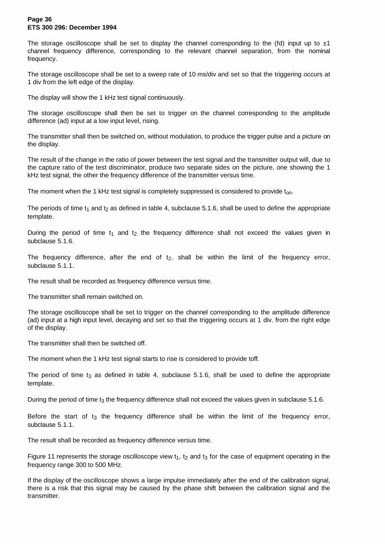
Page 36ETS 300 296: December 1994
The storage oscilloscope shall be set to display the channel corresponding to the (fd) input up to ±1channel frequency difference, corresponding to the relevant channel separation, from the nominalfrequency.
The storage oscilloscope shall be set to a sweep rate of 10 ms/div and set so that the triggering occurs at1 div from the left edge of the display.
The display will show the 1 kHz test signal continuously.
The storage oscilloscope shall then be set to trigger on the channel corresponding to the amplitudedifference (ad) input at a low input level, rising.
The transmitter shall then be switched on, without modulation, to produce the trigger pulse and a picture onthe display.
The result of the change in the ratio of power between the test signal and the transmitter output will, due tothe capture ratio of the test discriminator, produce two separate sides on the picture, one showing the 1kHz test signal, the other the frequency difference of the transmitter versus time.
The moment when the 1 kHz test signal is completely suppressed is considered to provide ton.
The periods of time t1 and t2 as defined in table 4, subclause 5.1.6, shall be used to define the appropriatetemplate.
During the period of time t1 and t2 the frequency difference shall not exceed the values given insubclause 5.1.6.
The frequency difference, after the end of t2, shall be within the limit of the frequency error,subclause 5.1.1.
The result shall be recorded as frequency difference versus time.
The transmitter shall remain switched on.
The storage oscilloscope shall be set to trigger on the channel corresponding to the amplitude difference(ad) input at a high input level, decaying and set so that the triggering occurs at 1 div. from the right edgeof the display.
The transmitter shall then be switched off.
The moment when the 1 kHz test signal starts to rise is considered to provide toff.
The period of time t3 as defined in table 4, subclause 5.1.6, shall be used to define the appropriatetemplate.
During the period of time t3 the frequency difference shall not exceed the values given in subclause 5.1.6.
Before the start of t3 the frequency difference shall be within the limit of the frequency error,subclause 5.1.1.
The result shall be recorded as frequency difference versus time.
Figure 11 represents the storage oscilloscope view t1, t2 and t3 for the case of equipment operating in thefrequency range 300 to 500 MHz.
If the display of the oscilloscope shows a large impulse immediately after the end of the calibration signal,there is a risk that this signal may be caused by the phase shift between the calibration signal and thetransmitter.

Page 37ETS 300 296: December 1994
To identify the source of the impulse, the following method can be used.
The impulse can be evaluated by repeating the test, e.g. for three times.
If the impulse remains constant in amplitude and exceeds the limit then the transmitter fails to meet thetest.
If the impulse changes amplitude it is a phase shift occurring from the method of testing and this impulseshall be disregarded in the assessment of the test results.
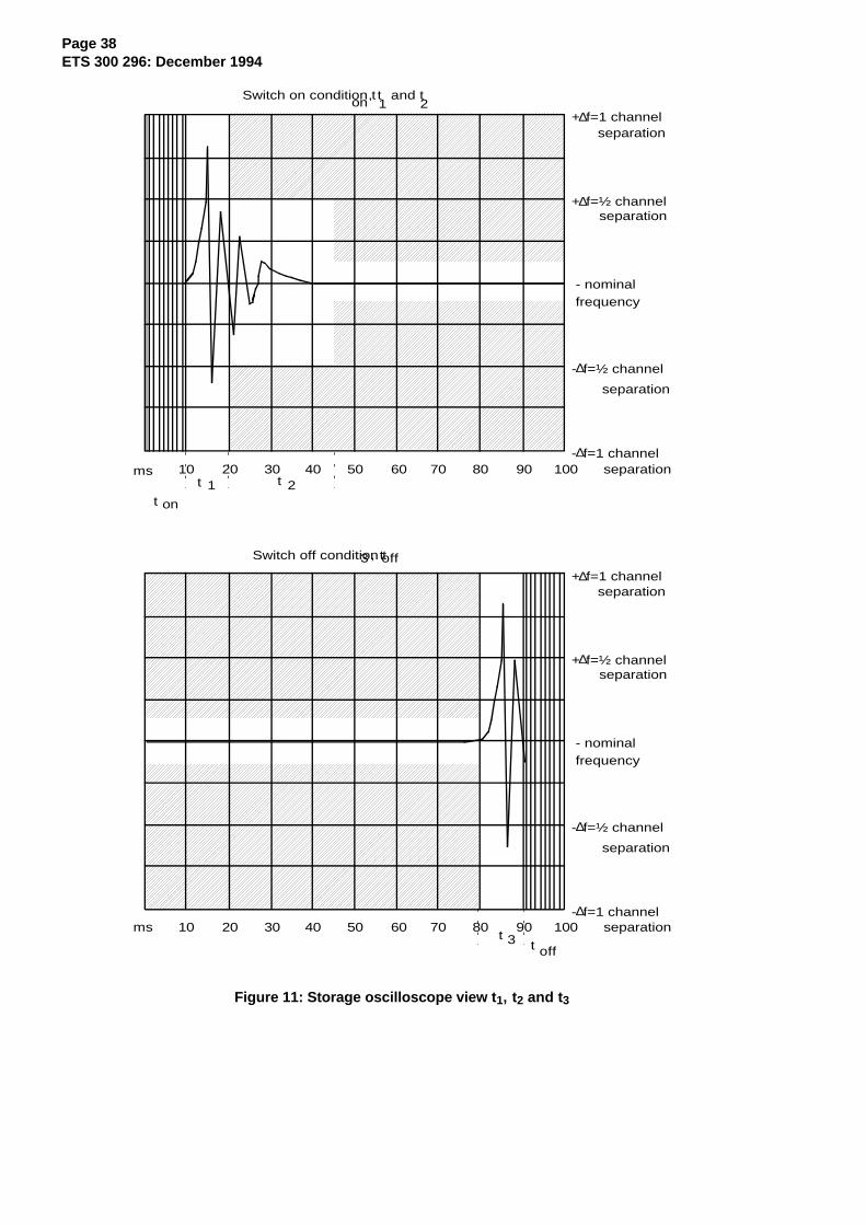
Page 38ETS 300 296: December 1994
+∆f=1 channelseparation
+∆f=½ channel separation
- nominal frequency
-∆f=½ channel
separation
-∆f=1 channelseparationms 10 20 30 40 50 60 70 80 90 100
+∆f=1 channelseparation
+∆f=½ channel separation
- nominal frequency
-∆f=½ channel
separation
-∆f=1 channelseparation10 20 30 40 50 60 70 80 90 100ms
Switch on condition ton
, t1
and t2
t t
t on
1 2
Switch off condition t, t3 off
t 3 t off
Figure 11: Storage oscilloscope view t 1, t2 and t 3
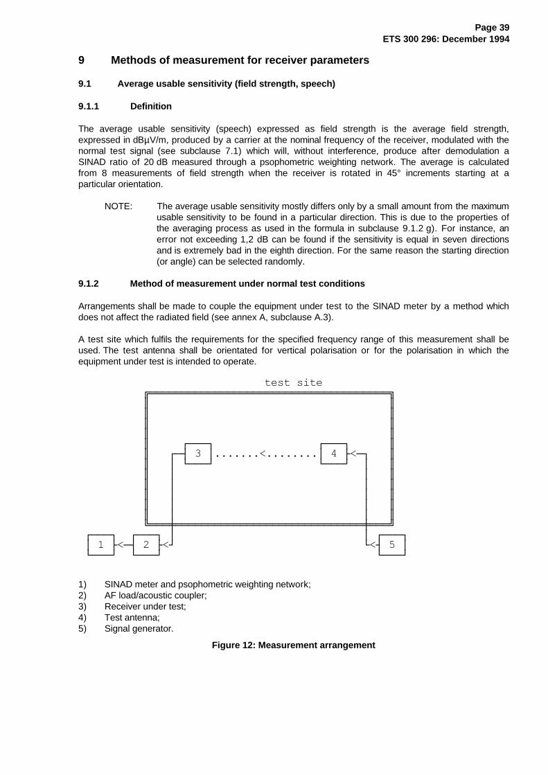
Page 39ETS 300 296: December 1994
9 Methods of measurement for receiver parameters
9.1 Average usable sensitivity (field strength, speech)
9.1.1 Definition
The average usable sensitivity (speech) expressed as field strength is the average field strength,expressed in dBµV/m, produced by a carrier at the nominal frequency of the receiver, modulated with thenormal test signal (see subclause 7.1) which will, without interference, produce after demodulation aSINAD ratio of 20 dB measured through a psophometric weighting network. The average is calculatedfrom 8 measurements of field strength when the receiver is rotated in 45° increments starting at aparticular orientation.
NOTE: The average usable sensitivity mostly differs only by a small amount from the maximumusable sensitivity to be found in a particular direction. This is due to the properties ofthe averaging process as used in the formula in subclause 9.1.2 g). For instance, anerror not exceeding 1,2 dB can be found if the sensitivity is equal in seven directionsand is extremely bad in the eighth direction. For the same reason the starting direction(or angle) can be selected randomly.
9.1.2 Method of measurement under normal test conditions
Arrangements shall be made to couple the equipment under test to the SINAD meter by a method whichdoes not affect the radiated field (see annex A, subclause A.3).
A test site which fulfils the requirements for the specified frequency range of this measurement shall beused. The test antenna shall be orientated for vertical polarisation or for the polarisation in which theequipment under test is intended to operate.
test site ÉÍÍÍÍÍÍÍÍÍÍÍÍÍÍÍÍÍÍÍÍÍÍÍÍÍÍÍÍÍÍÍÍÍÍÍÍÍ» º º º º º º º º º ÚÄÄÄ¿ ÚÄÄÄ¿ º º ÚÄ´ 3 ³.......<........³ 4 Ã<Ä¿ º º ³ ÀÄÄÄÙ ÀÄÄÄÙ ³ º º ³ ³ º º ³ ³ º º ³ ³ º º ³ ³ º º ³ ³ º ÈÍÍÍØÍÍÍÍÍÍÍÍÍÍÍÍÍÍÍÍÍÍÍÍÍÍÍÍÍÍÍÍÍØÍÍͼ ÚÄÄÄ¿ ÚÄÄÄ¿ ³ ³ ÚÄÄÄ¿ ³ 1 Ã<Ä´ 2 Ã<Ù À<´ 5 ³ ÀÄÄÄÙ ÀÄÄÄÙ ÀÄÄÄÙ
1) SINAD meter and psophometric weighting network;2) AF load/acoustic coupler;3) Receiver under test;4) Test antenna;5) Signal generator.
Figure 12: Measurement arrangement
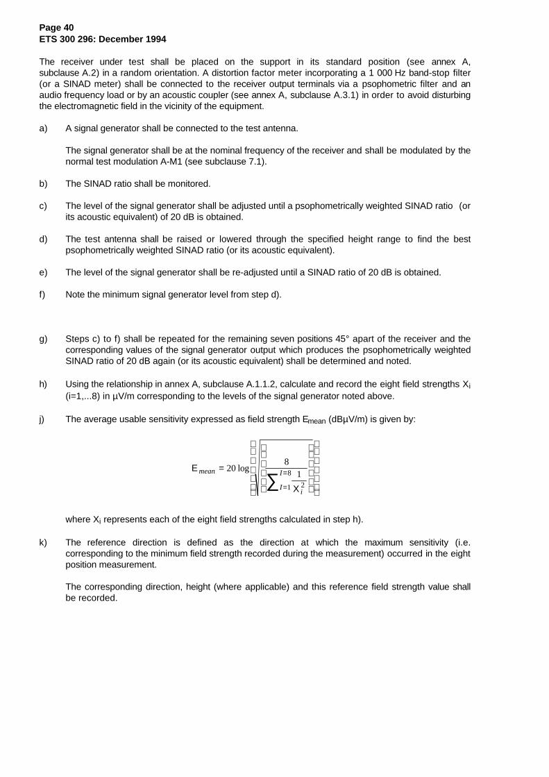
Page 40ETS 300 296: December 1994
The receiver under test shall be placed on the support in its standard position (see annex A,subclause A.2) in a random orientation. A distortion factor meter incorporating a 1 000 Hz band-stop filter(or a SINAD meter) shall be connected to the receiver output terminals via a psophometric filter and anaudio frequency load or by an acoustic coupler (see annex A, subclause A.3.1) in order to avoid disturbingthe electromagnetic field in the vicinity of the equipment.
a) A signal generator shall be connected to the test antenna.
The signal generator shall be at the nominal frequency of the receiver and shall be modulated by thenormal test modulation A-M1 (see subclause 7.1).
b) The SINAD ratio shall be monitored.
c) The level of the signal generator shall be adjusted until a psophometrically weighted SINAD ratio (orits acoustic equivalent) of 20 dB is obtained.
d) The test antenna shall be raised or lowered through the specified height range to find the bestpsophometrically weighted SINAD ratio (or its acoustic equivalent).
e) The level of the signal generator shall be re-adjusted until a SINAD ratio of 20 dB is obtained.
f) Note the minimum signal generator level from step d).
g) Steps c) to f) shall be repeated for the remaining seven positions 45° apart of the receiver and thecorresponding values of the signal generator output which produces the psophometrically weightedSINAD ratio of 20 dB again (or its acoustic equivalent) shall be determined and noted.
h) Using the relationship in annex A, subclause A.1.1.2, calculate and record the eight field strengths Xi(i=1,...8) in µV/m corresponding to the levels of the signal generator noted above.
j) The average usable sensitivity expressed as field strength Emean (dBµV/m) is given by:
Ε
Χ
mean
iI
I=
=
=∑20
81
21
8log
where Xi represents each of the eight field strengths calculated in step h).
k) The reference direction is defined as the direction at which the maximum sensitivity (i.e.corresponding to the minimum field strength recorded during the measurement) occurred in the eightposition measurement.
The corresponding direction, height (where applicable) and this reference field strength value shallbe recorded.
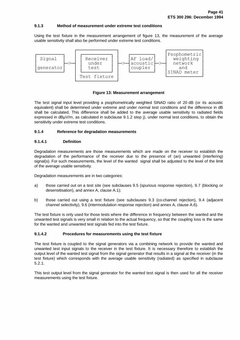
Page 41ETS 300 296: December 1994
9.1.3 Method of measurement under extreme test conditions
Using the test fixture in the measurement arrangement of figure 13, the measurement of the averageusable sensitivity shall also be performed under extreme test conditions.
ÚÄÄÄÄÄÄÄÄÄÄÄÄÄÄ¿ ÚÄÄÄÄÄÄÄÄÄÄÄÄ¿ÚÄÄÄÄÄÄÄÄÄ¿ ³ ÚÄÄÄÄÄÄÄÄÄÄ¿ ³ ÚÄÄÄÄÄÄÄÄ¿ ³Psophometric³³ Signal ³ ³ ³ Receiver ³ ³ ³AF load/³ ³ weighting ³³ ÃÄ>Ä´ ³ under ³ ÃÄ>Ä´acousticÃÄ>Ä´ network ³³generator³ ³ ³ test ³ ³ ³coupler ³ ³ and ³ÀÄÄÄÄÄÄÄÄÄÙ ³ ÀÄÄÄÄÄÄÄÄÄÄÙ ³ ÀÄÄÄÄÄÄÄÄÙ ³SINAD meter ³ ³ Test fixture ³ ÀÄÄÄÄÄÄÄÄÄÄÄÄÙ ÀÄÄÄÄÄÄÄÄÄÄÄÄÄÄÙ
Figure 13: Measurement arrangement
The test signal input level providing a psophometrically weighted SINAD ratio of 20 dB (or its acousticequivalent) shall be determined under extreme and under normal test conditions and the difference in dBshall be calculated. This difference shall be added to the average usable sensitivity to radiated fieldsexpressed in dBµV/m, as calculated in subclause 9.1.2 step j), under normal test conditions, to obtain thesensitivity under extreme test conditions.
9.1.4 Reference for degradation measurements
9.1.4.1 Definition
Degradation measurements are those measurements which are made on the receiver to establish thedegradation of the performance of the receiver due to the presence of (an) unwanted (interfering)signal(s). For such measurements, the level of the wanted signal shall be adjusted to the level of the limitof the average usable sensitivity.
Degradation measurements are in two categories:
a) those carried out on a test site (see subclauses 9.5 (spurious response rejection), 9.7 (blocking ordesensitisation), and annex A, clause A.1);
b) those carried out using a test fixture (see subclauses 9.3 (co-channel rejection), 9.4 (adjacentchannel selectivity), 9.6 (intermodulation response rejection) and annex A, clause A.6).
The test fixture is only used for those tests where the difference in frequency between the wanted and theunwanted test signals is very small in relation to the actual frequency, so that the coupling loss is the samefor the wanted and unwanted test signals fed into the test fixture.
9.1.4.2 Procedures for measurements using the test fixture
The test fixture is coupled to the signal generators via a combining network to provide the wanted andunwanted test input signals to the receiver in the test fixture. It is necessary therefore to establish theoutput level of the wanted test signal from the signal generator that results in a signal at the receiver (in thetest fixture) which corresponds with the average usable sensitivity (radiated) as specified in subclause5.2.1.
This test output level from the signal generator for the wanted test signal is then used for all the receivermeasurements using the test fixture.
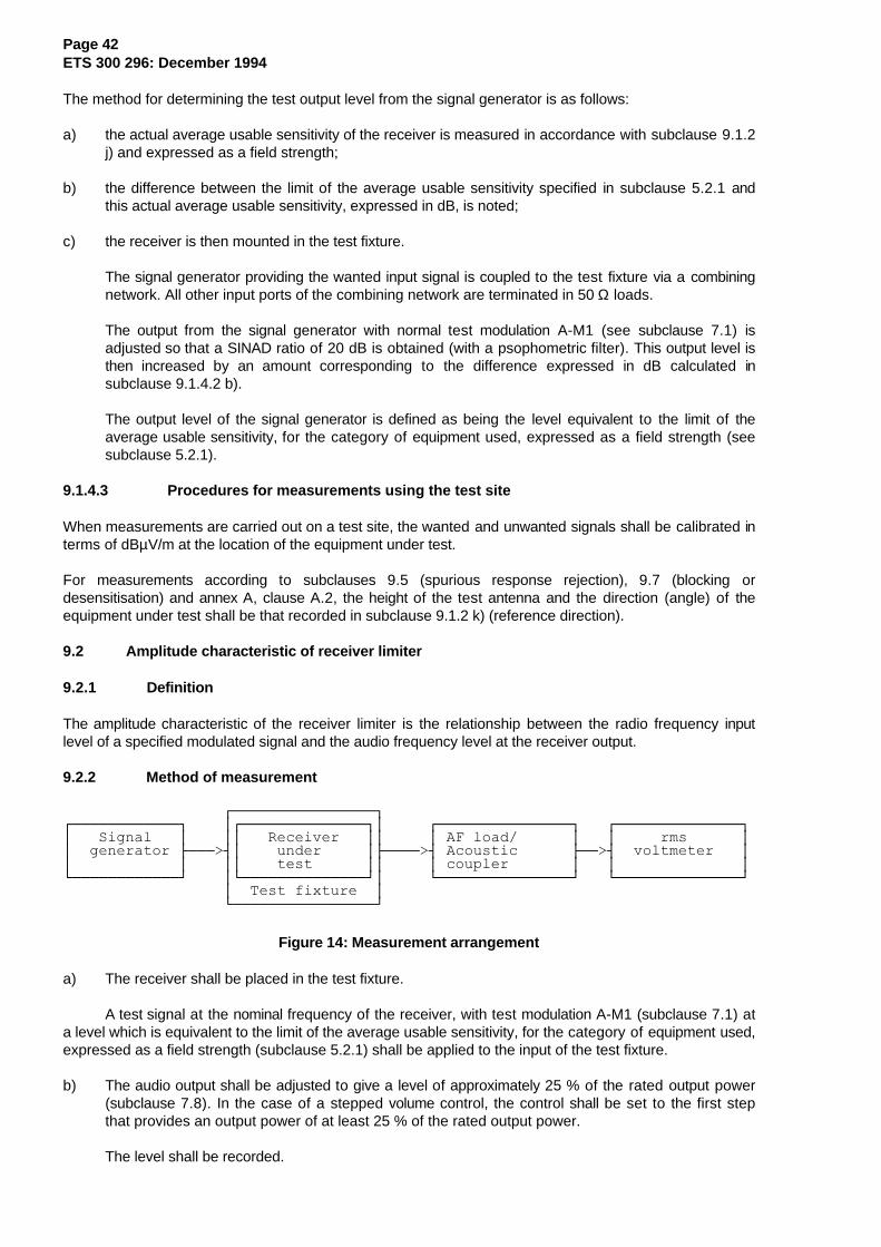
Page 42ETS 300 296: December 1994
The method for determining the test output level from the signal generator is as follows:
a) the actual average usable sensitivity of the receiver is measured in accordance with subclause 9.1.2j) and expressed as a field strength;
b) the difference between the limit of the average usable sensitivity specified in subclause 5.2.1 andthis actual average usable sensitivity, expressed in dB, is noted;
c) the receiver is then mounted in the test fixture.
The signal generator providing the wanted input signal is coupled to the test fixture via a combiningnetwork. All other input ports of the combining network are terminated in 50 Ω loads.
The output from the signal generator with normal test modulation A-M1 (see subclause 7.1) isadjusted so that a SINAD ratio of 20 dB is obtained (with a psophometric filter). This output level isthen increased by an amount corresponding to the difference expressed in dB calculated insubclause 9.1.4.2 b).
The output level of the signal generator is defined as being the level equivalent to the limit of theaverage usable sensitivity, for the category of equipment used, expressed as a field strength (seesubclause 5.2.1).
9.1.4.3 Procedures for measurements using the test site
When measurements are carried out on a test site, the wanted and unwanted signals shall be calibrated interms of dBµV/m at the location of the equipment under test.
For measurements according to subclauses 9.5 (spurious response rejection), 9.7 (blocking ordesensitisation) and annex A, clause A.2, the height of the test antenna and the direction (angle) of theequipment under test shall be that recorded in subclause 9.1.2 k) (reference direction).
9.2 Amplitude characteristic of receiver limiter
9.2.1 Definition
The amplitude characteristic of the receiver limiter is the relationship between the radio frequency inputlevel of a specified modulated signal and the audio frequency level at the receiver output.
9.2.2 Method of measurement
ÚÄÄÄÄÄÄÄÄÄÄÄÄÄÄÄÄ¿ÚÄÄÄÄÄÄÄÄÄÄÄÄ¿ ³ÚÄÄÄÄÄÄÄÄÄÄÄÄÄÄ¿³ ÚÄÄÄÄÄÄÄÄÄÄÄÄÄÄÄ¿ ÚÄÄÄÄÄÄÄÄÄÄÄÄÄÄ¿³ Signal ³ ³³ Receiver ³³ ³ AF load/ ³ ³ rms ³³ generator ÃÄÄÄ>´³ under ³ÃÄÄÄÄ>´ Acoustic ÃÄÄ>´ voltmeter ³³ ³ ³³ test ³³ ³ coupler ³ ³ ³ÀÄÄÄÄÄÄÄÄÄÄÄÄÙ ³ÀÄÄÄÄÄÄÄÄÄÄÄÄÄÄÙ³ ÀÄÄÄÄÄÄÄÄÄÄÄÄÄÄÄÙ ÀÄÄÄÄÄÄÄÄÄÄÄÄÄÄÙ ³ Test fixture ³ ÀÄÄÄÄÄÄÄÄÄÄÄÄÄÄÄÄÙ
Figure 14: Measurement arrangement
a) The receiver shall be placed in the test fixture.
A test signal at the nominal frequency of the receiver, with test modulation A-M1 (subclause 7.1) ata level which is equivalent to the limit of the average usable sensitivity, for the category of equipment used,expressed as a field strength (subclause 5.2.1) shall be applied to the input of the test fixture.
b) The audio output shall be adjusted to give a level of approximately 25 % of the rated output power(subclause 7.8). In the case of a stepped volume control, the control shall be set to the first stepthat provides an output power of at least 25 % of the rated output power.
The level shall be recorded.
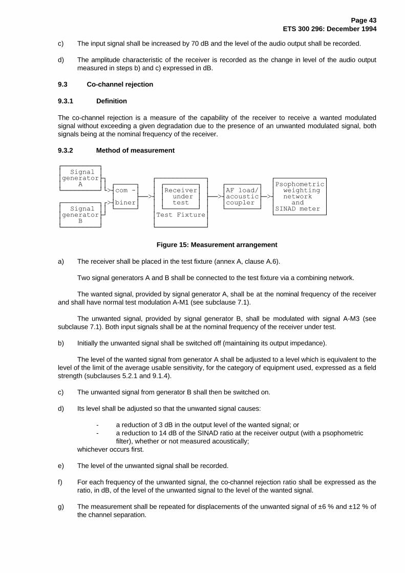
Page 43ETS 300 296: December 1994
c) The input signal shall be increased by 70 dB and the level of the audio output shall be recorded.
d) The amplitude characteristic of the receiver is recorded as the change in level of the audio outputmeasured in steps b) and c) expressed in dB.
9.3 Co-channel rejection
9.3.1 Definition
The co-channel rejection is a measure of the capability of the receiver to receive a wanted modulatedsignal without exceeding a given degradation due to the presence of an unwanted modulated signal, bothsignals being at the nominal frequency of the receiver.
9.3.2 Method of measurement
ÚÄÄÄÄÄÄÄÄÄ¿³ Signal ³³generatorÿ ÚÄÄÄÄÄÄÄÄÄÄÄÄ¿ ÚÄÄÄÄÄÄÄÄÄÄÄÄ¿³ A ³³ ÚÄÄÄÄÄ¿ ³ ÚÄÄÄÄÄÄÄÄ¿ ³ ÚÄÄÄÄÄÄÄÄ¿ ³Psophometric³ÀÄÄÄÄÄÄÄÄÄÙÀ>´com -³ ³ ³Receiver³ ³ ³AF load/³ ³ weighting ³ ³ ÃÄÄ>´ ³ under ³ ÃÄÄ>´acousticÃÄ>´ network ³ÚÄÄÄÄÄÄÄÄÄ¿Ú>´biner³ ³ ³ test ³ ³ ³coupler ³ ³ and ³³ Signal ³³ ÀÄÄÄÄÄÙ ³ ÀÄÄÄÄÄÄÄÄÙ ³ ÀÄÄÄÄÄÄÄÄÙ ³SINAD meter ³³generatorÃÙ ³Test Fixture³ ÀÄÄÄÄÄÄÄÄÄÄÄÄÙ³ B ³ ³ ³ÀÄÄÄÄÄÄÄÄÄÙ ÀÄÄÄÄÄÄÄÄÄÄÄÄÙ
Figure 15: Measurement arrangement
a) The receiver shall be placed in the test fixture (annex A, clause A.6).
Two signal generators A and B shall be connected to the test fixture via a combining network.
The wanted signal, provided by signal generator A, shall be at the nominal frequency of the receiverand shall have normal test modulation A-M1 (see subclause 7.1).
The unwanted signal, provided by signal generator B, shall be modulated with signal A-M3 (seesubclause 7.1). Both input signals shall be at the nominal frequency of the receiver under test.
b) Initially the unwanted signal shall be switched off (maintaining its output impedance).
The level of the wanted signal from generator A shall be adjusted to a level which is equivalent to thelevel of the limit of the average usable sensitivity, for the category of equipment used, expressed as a fieldstrength (subclauses 5.2.1 and 9.1.4).
c) The unwanted signal from generator B shall then be switched on.
d) Its level shall be adjusted so that the unwanted signal causes:
- a reduction of 3 dB in the output level of the wanted signal; or- a reduction to 14 dB of the SINAD ratio at the receiver output (with a psophometric
filter), whether or not measured acoustically;whichever occurs first.
e) The level of the unwanted signal shall be recorded.
f) For each frequency of the unwanted signal, the co-channel rejection ratio shall be expressed as theratio, in dB, of the level of the unwanted signal to the level of the wanted signal.
g) The measurement shall be repeated for displacements of the unwanted signal of ±6 % and ±12 % ofthe channel separation.
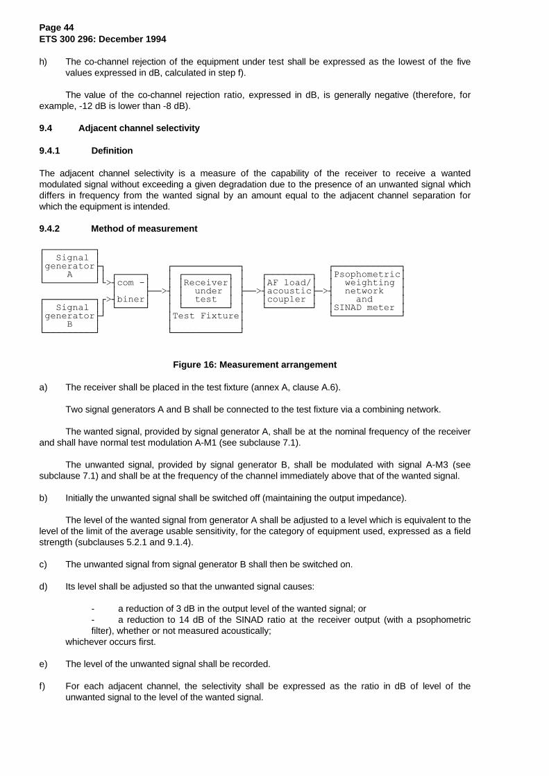
Page 44ETS 300 296: December 1994
h) The co-channel rejection of the equipment under test shall be expressed as the lowest of the fivevalues expressed in dB, calculated in step f).
The value of the co-channel rejection ratio, expressed in dB, is generally negative (therefore, forexample, -12 dB is lower than -8 dB).
9.4 Adjacent channel selectivity
9.4.1 Definition
The adjacent channel selectivity is a measure of the capability of the receiver to receive a wantedmodulated signal without exceeding a given degradation due to the presence of an unwanted signal whichdiffers in frequency from the wanted signal by an amount equal to the adjacent channel separation forwhich the equipment is intended.
9.4.2 Method of measurement
ÚÄÄÄÄÄÄÄÄÄ¿³ Signal ³³generatorÿ ÚÄÄÄÄÄÄÄÄÄÄÄÄ¿ ÚÄÄÄÄÄÄÄÄÄÄÄÄ¿³ A ³³ ÚÄÄÄÄÄ¿ ³ ÚÄÄÄÄÄÄÄÄ¿ ³ ÚÄÄÄÄÄÄÄÄ¿ ³Psophometric³ÀÄÄÄÄÄÄÄÄÄÙÀ>´com -³ ³ ³Receiver³ ³ ³AF load/³ ³ weighting ³ ³ ÃÄÄ>´ ³ under ³ ÃÄÄ>´acousticÃÄ>´ network ³ÚÄÄÄÄÄÄÄÄÄ¿Ú>´biner³ ³ ³ test ³ ³ ³coupler ³ ³ and ³³ Signal ³³ ÀÄÄÄÄÄÙ ³ ÀÄÄÄÄÄÄÄÄÙ ³ ÀÄÄÄÄÄÄÄÄÙ ³SINAD meter ³³generatorÃÙ ³Test Fixture³ ÀÄÄÄÄÄÄÄÄÄÄÄÄÙ³ B ³ ³ ³ÀÄÄÄÄÄÄÄÄÄÙ ÀÄÄÄÄÄÄÄÄÄÄÄÄÙ
Figure 16: Measurement arrangement
a) The receiver shall be placed in the test fixture (annex A, clause A.6).
Two signal generators A and B shall be connected to the test fixture via a combining network.
The wanted signal, provided by signal generator A, shall be at the nominal frequency of the receiverand shall have normal test modulation A-M1 (see subclause 7.1).
The unwanted signal, provided by signal generator B, shall be modulated with signal A-M3 (seesubclause 7.1) and shall be at the frequency of the channel immediately above that of the wanted signal.
b) Initially the unwanted signal shall be switched off (maintaining the output impedance).
The level of the wanted signal from generator A shall be adjusted to a level which is equivalent to thelevel of the limit of the average usable sensitivity, for the category of equipment used, expressed as a fieldstrength (subclauses 5.2.1 and 9.1.4).
c) The unwanted signal from signal generator B shall then be switched on.
d) Its level shall be adjusted so that the unwanted signal causes:
- a reduction of 3 dB in the output level of the wanted signal; or- a reduction to 14 dB of the SINAD ratio at the receiver output (with a psophometricfilter), whether or not measured acoustically;
whichever occurs first.
e) The level of the unwanted signal shall be recorded.
f) For each adjacent channel, the selectivity shall be expressed as the ratio in dB of level of theunwanted signal to the level of the wanted signal.
Page 45ETS 300 296: December 1994
It shall then be converted back into field strengths of the unwanted signals at the receiver location and expressed in dBµV/m.
g) The measurement shall be repeated with the unwanted signal at the frequency of the channel belowthat of the wanted signal.
h) The adjacent channel selectivity of the equipment under test shall be expressed as the lower of thetwo values calculated in step f) for the upper and lower channels nearest to the receiving channel.
j) The measurement shall be repeated under extreme test conditions (subclauses 6.4.1 and 6.4.2applied simultaneously), with the level of the wanted signal adjusted to a level which is equivalent tothe level of the limit of the average usable sensitivity (under extreme test conditions), for thecategory of equipment used, expressed as a field strength (see subclauses 5.2.1 and 9.1.4).
9.5 Spurious response rejection
Spurious responses may occur at all frequencies throughout the frequency spectrum and the requirementsof this ETS shall be met for all frequencies. However, for practical reasons the measurements for typetesting shall be performed as specified in this ETS. More specifically, this method of measurement is notintended to capture all spurious responses but selects those that have a high probability of being present.However, in a limited frequency range close to the nominal frequency of the receiver, it has beenconsidered impossible to determine the probability of a spurious response and therefore a search shall beperformed over this limited frequency range. This method provides a high degree of confidence that theequipment also meets the requirements at frequencies not being measured.
9.5.1 Definition
The spurious response rejection is a measure of the capability of the receiver to receive a wantedmodulated signal without exceeding a given degradation due to the presence of an unwanted modulatedsignal at any other frequency, at which a response is obtained.
9.5.2 Introduction to the method of measurement
To determine the frequencies at which spurious responses can occur the following calculations shall bemade:
a) calculation of the "limited frequency range".
The limited frequency range is defined as the frequency of the local oscillator signal (fLO) applied tothe 1st mixer of the receiver plus or minus the sum of the intermediate frequencies (fI1,...fIn) and ahalf the switching range (sr) of the receiver, see clause 4.
Hence, the frequency fl of the limited frequency range is
LO j=1j=n
Ij l LO j=1j=n
Ijf - f - sr
2 f f + f +
sr
2∑ ≤ ≤ ∑
Page 46ETS 300 296: December 1994
b) calculation of frequencies outside the limited frequency range.
A calculation of the frequencies at which spurious responses can occur outside the rangedetermined in a) is made for the remainder of the frequency range of interest, as appropriate, seesubclause 9.5.5 d).
The frequencies outside the limited frequency range are equal to the harmonics of the frequency ofthe local oscillator signal (fLO) applied to the 1st mixer of the receiver plus or minus the 1stintermediate frequency (fI1) of the receiver.
Hence, the frequencies of these spurious responses are:
nfLO ± fI1,
where n is an integer greater than or equal to 2.
The measurement of the first image response of the receiver shall initially be made to verify the calculationof spurious response frequencies.
For the calculations a) and b) above, the manufacturer shall state the frequency of the receiver, thefrequency of the local oscillator signal (fLO) applied to the 1st mixer of the receiver, the intermediatefrequencies (fI1, fI2 etc.), and the switching range (sr) of the receiver.
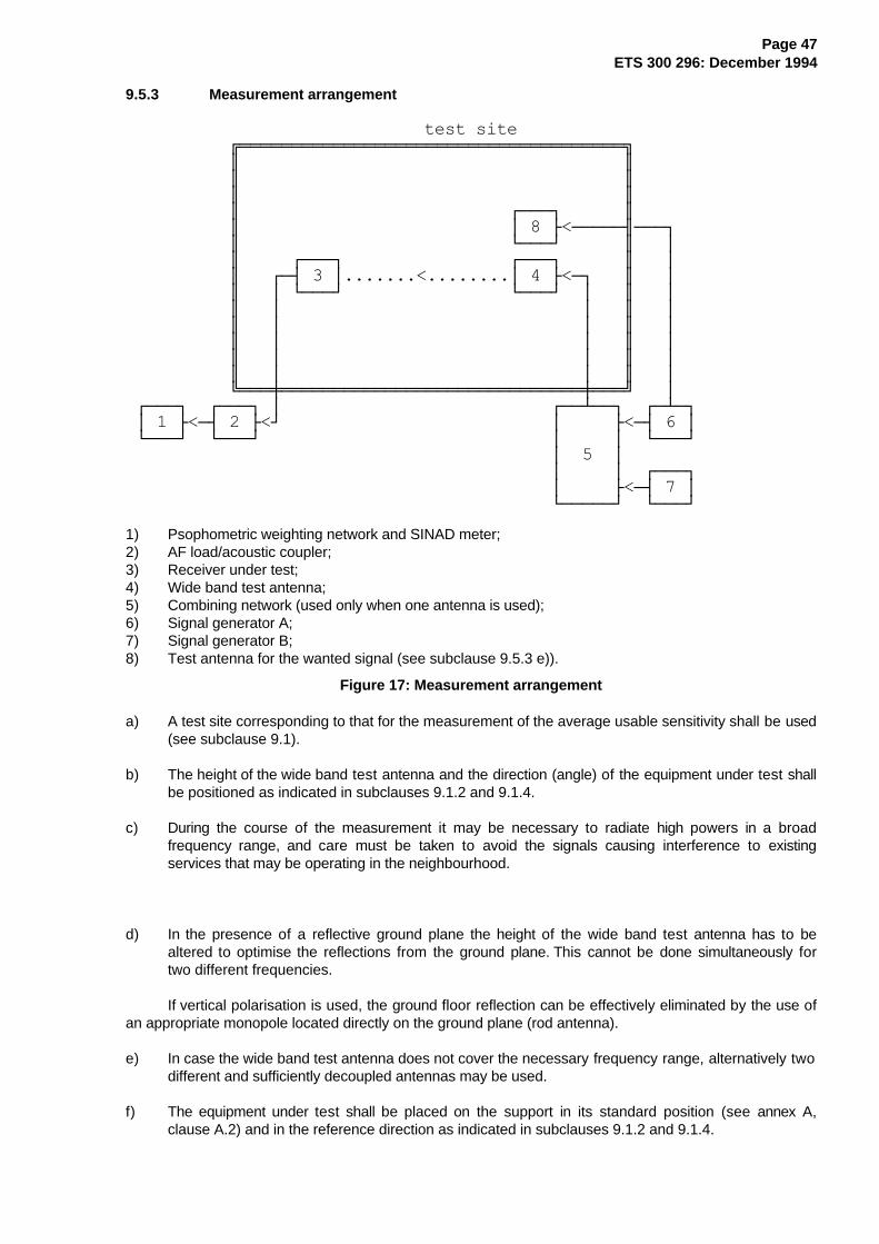
Page 47ETS 300 296: December 1994
9.5.3 Measurement arrangement
test site ÉÍÍÍÍÍÍÍÍÍÍÍÍÍÍÍÍÍÍÍÍÍÍÍÍÍÍÍÍÍÍÍÍÍÍÍÍÍ» º º º º º º º ÚÄÄÄ¿ º º ³ 8 Ã<ÄÄÄÄĶÄÄÄ¿ º ÀÄÄÄÙ º ³ º ÚÄÄÄ¿ ÚÄÄÄ¿ º ³ º ÚÄ´ 3 ³.......<........³ 4 Ã<Ä¿ º ³ º ³ ÀÄÄÄÙ ÀÄÄÄÙ ³ º ³ º ³ ³ º ³ º ³ ³ º ³ º ³ ³ º ³ º ³ ³ º ³ º ³ ³ º ³ ÈÍÍÍØÍÍÍÍÍÍÍÍÍÍÍÍÍÍÍÍÍÍÍÍÍÍÍÍÍÍÍÍÍØÍÍͼ ³ ÚÄÄÄ¿ ÚÄÄÄ¿ ³ ÚÄÄÁÄÄ¿ ÚÄÁÄ¿ ³ 1 Ã<Ä´ 2 Ã<Ù ³ Ã<Ä´ 6 ³ ÀÄÄÄÙ ÀÄÄÄÙ ³ ³ ÀÄÄÄÙ ³ 5 ³ ³ ³ ÚÄÄÄ¿ ³ Ã<Ä´ 7 ³ ÀÄÄÄÄÄÙ ÀÄÄÄÙ
1) Psophometric weighting network and SINAD meter;2) AF load/acoustic coupler;3) Receiver under test;4) Wide band test antenna;5) Combining network (used only when one antenna is used);6) Signal generator A;7) Signal generator B;8) Test antenna for the wanted signal (see subclause 9.5.3 e)).
Figure 17: Measurement arrangement
a) A test site corresponding to that for the measurement of the average usable sensitivity shall be used(see subclause 9.1).
b) The height of the wide band test antenna and the direction (angle) of the equipment under test shallbe positioned as indicated in subclauses 9.1.2 and 9.1.4.
c) During the course of the measurement it may be necessary to radiate high powers in a broadfrequency range, and care must be taken to avoid the signals causing interference to existingservices that may be operating in the neighbourhood.
d) In the presence of a reflective ground plane the height of the wide band test antenna has to bealtered to optimise the reflections from the ground plane. This cannot be done simultaneously fortwo different frequencies.
If vertical polarisation is used, the ground floor reflection can be effectively eliminated by the use ofan appropriate monopole located directly on the ground plane (rod antenna).
e) In case the wide band test antenna does not cover the necessary frequency range, alternatively twodifferent and sufficiently decoupled antennas may be used.
f) The equipment under test shall be placed on the support in its standard position (see annex A,clause A.2) and in the reference direction as indicated in subclauses 9.1.2 and 9.1.4.
Page 48ETS 300 296: December 1994
9.5.4 Method of the search
The measurement shall be performed as follows, using the measurement arrangement of subclause 9.5.3.
a) Two signal generators A and B shall be connected to the wide band test antenna via a combiningnetwork, where appropriate, or alternatively to two different antennas in accordance with subclause9.5.3 e).
The wanted signal, provided by signal generator A, shall be at the nominal frequency of the receiverand shall have normal test modulation A-M1 (see subclause 7.1).
The unwanted signal, provided by signal generator B, shall be modulated with a frequency of 400 Hzat a level producing a deviation of ±5 kHz.
b) Initially the unwanted signal shall be switched off (maintaining the output impedance).
The level of the wanted signal from generator A shall be adjusted to the level of the limit of theaverage usable sensitivity, for the category of equipment used, expressed as a field strength, and by usingthe calibration in the procedure of subclause 9.1.4.3 (see subclauses 5.2.1 and 9.1.4).
c) The unwanted signal from generator B shall then be switched on.
Its level shall be adjusted to provide a field strength which is at least 10 dB above the limit of thespurious response rejection (see subclause 5.2.5) measured at the receiver location, even when on sometypes of test sites the level of the unwanted signal varies considerably with the frequency due to groundreflections.
The frequency of the unwanted signal shall be varied in increments of 10 kHz over the limitedfrequency range (see subclause 9.5.2 a) and over the frequencies in accordance with the calculationsoutside of this frequency range (see subclause 9.5.2 b)).
d) The SINAD ratio shall be monitored.
e) If the SINAD ratio is better than 20 dB then no spurious response effects have been detected andthe measurement shall be continued on the next increment of frequency.
f) If the SINAD ratio is worse than 20 dB then the level of the unwanted signal shall be reduced insteps of 1 dB until a SINAD ratio of 20 dB or better is obtained.
g) In the case where a reflective ground floor is used the antenna height shall be varied as appropriate,at each change of unwanted signal level in an attempt to obtain a SINAD ratio of 20 dB or better.
The test antenna may not need to be raised or lowered if a test site according to annex A,subclause A.1.2 is used, or if the ground floor reflection can effectively be eliminated (see subclause9.5.3 d).
h) The frequency of any spurious response detected during the search, and the antenna position andits height shall be recorded for the use in measurements in accordance with subclause 9.5.5.
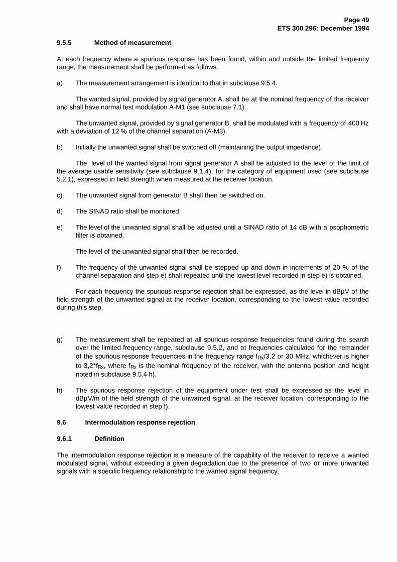
Page 49ETS 300 296: December 1994
9.5.5 Method of measurement
At each frequency where a spurious response has been found, within and outside the limited frequencyrange, the measurement shall be performed as follows.
a) The measurement arrangement is identical to that in subclause 9.5.4.
The wanted signal, provided by signal generator A, shall be at the nominal frequency of the receiverand shall have normal test modulation A-M1 (see subclause 7.1).
The unwanted signal, provided by signal generator B, shall be modulated with a frequency of 400 Hzwith a deviation of 12 % of the channel separation (A-M3).
b) Initially the unwanted signal shall be switched off (maintaining the output impedance).
The level of the wanted signal from signal generator A shall be adjusted to the level of the limit ofthe average usable sensitivity (see subclause 9.1.4), for the category of equipment used (see subclause5.2.1), expressed in field strength when measured at the receiver location.
c) The unwanted signal from generator B shall then be switched on.
d) The SINAD ratio shall be monitored.
e) The level of the unwanted signal shall be adjusted until a SINAD ratio of 14 dB with a psophometricfilter is obtained.
The level of the unwanted signal shall then be recorded.
f) The frequency of the unwanted signal shall be stepped up and down in increments of 20 % of thechannel separation and step e) shall repeated until the lowest level recorded in step e) is obtained.
For each frequency the spurious response rejection shall be expressed, as the level in dBµV of thefield strength of the unwanted signal at the receiver location, corresponding to the lowest value recordedduring this step.
g) The measurement shall be repeated at all spurious response frequencies found during the searchover the limited frequency range, subclause 9.5.2, and at frequencies calculated for the remainderof the spurious response frequencies in the frequency range fRx/3,2 or 30 MHz, whichever is higherto 3,2*fRx, where fRx is the nominal frequency of the receiver, with the antenna position and heightnoted in subclause 9.5.4 h).
h) The spurious response rejection of the equipment under test shall be expressed as the level indBµV/m of the field strength of the unwanted signal, at the receiver location, corresponding to thelowest value recorded in step f).
9.6 Intermodulation response rejection
9.6.1 Definition
The intermodulation response rejection is a measure of the capability of the receiver to receive a wantedmodulated signal, without exceeding a given degradation due to the presence of two or more unwantedsignals with a specific frequency relationship to the wanted signal frequency.
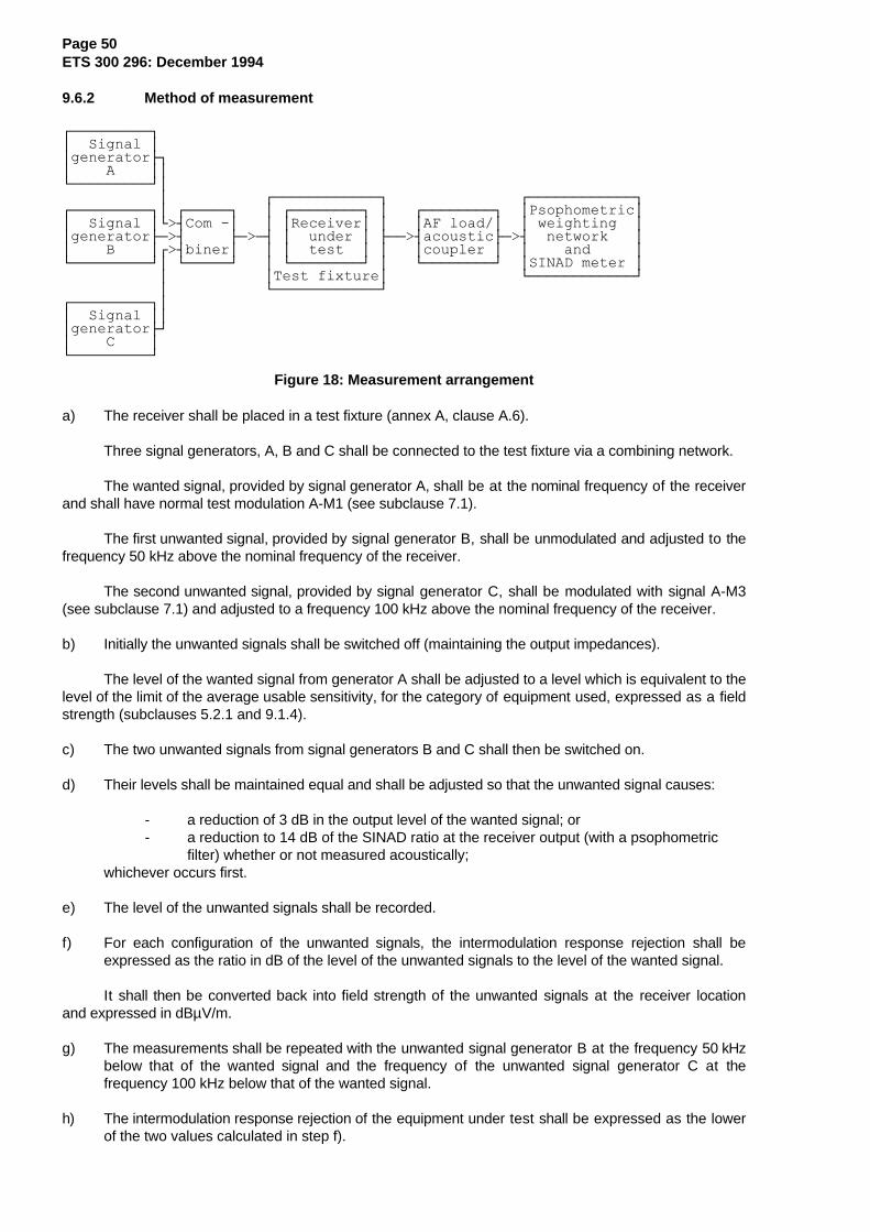
Page 50ETS 300 296: December 1994
9.6.2 Method of measurement
ÚÄÄÄÄÄÄÄÄÄ¿³ Signal ³³generatorÿ³ A ³³ÀÄÄÄÄÄÄÄÄÄÙ³ ³ ÚÄÄÄÄÄÄÄÄÄÄÄÄ¿ ÚÄÄÄÄÄÄÄÄÄÄÄÄ¿ÚÄÄÄÄÄÄÄÄÄ¿³ ÚÄÄÄÄÄ¿ ³ ÚÄÄÄÄÄÄÄÄ¿ ³ ÚÄÄÄÄÄÄÄÄ¿ ³Psophometric³³ Signal ³À>´Com -³ ³ ³Receiver³ ³ ³AF load/³ ³ weighting ³³generatorÃÄ>´ ÃÄ>Ä´ ³ under ³ ÃÄÄ>´acousticÃÄ>´ network ³³ B ³Ú>´biner³ ³ ³ test ³ ³ ³coupler ³ ³ and ³ÀÄÄÄÄÄÄÄÄÄÙ³ ÀÄÄÄÄÄÙ ³ ÀÄÄÄÄÄÄÄÄÙ ³ ÀÄÄÄÄÄÄÄÄÙ ³SINAD meter ³ ³ ³Test fixture³ ÀÄÄÄÄÄÄÄÄÄÄÄÄÙ ³ ÀÄÄÄÄÄÄÄÄÄÄÄÄÙÚÄÄÄÄÄÄÄÄÄ¿³³ Signal ³³³generatorÃÙ³ C ³ÀÄÄÄÄÄÄÄÄÄÙ
Figure 18: Measurement arrangement
a) The receiver shall be placed in a test fixture (annex A, clause A.6).
Three signal generators, A, B and C shall be connected to the test fixture via a combining network.
The wanted signal, provided by signal generator A, shall be at the nominal frequency of the receiverand shall have normal test modulation A-M1 (see subclause 7.1).
The first unwanted signal, provided by signal generator B, shall be unmodulated and adjusted to thefrequency 50 kHz above the nominal frequency of the receiver.
The second unwanted signal, provided by signal generator C, shall be modulated with signal A-M3(see subclause 7.1) and adjusted to a frequency 100 kHz above the nominal frequency of the receiver.
b) Initially the unwanted signals shall be switched off (maintaining the output impedances).
The level of the wanted signal from generator A shall be adjusted to a level which is equivalent to thelevel of the limit of the average usable sensitivity, for the category of equipment used, expressed as a fieldstrength (subclauses 5.2.1 and 9.1.4).
c) The two unwanted signals from signal generators B and C shall then be switched on.
d) Their levels shall be maintained equal and shall be adjusted so that the unwanted signal causes:
- a reduction of 3 dB in the output level of the wanted signal; or- a reduction to 14 dB of the SINAD ratio at the receiver output (with a psophometric
filter) whether or not measured acoustically;whichever occurs first.
e) The level of the unwanted signals shall be recorded.
f) For each configuration of the unwanted signals, the intermodulation response rejection shall beexpressed as the ratio in dB of the level of the unwanted signals to the level of the wanted signal.
It shall then be converted back into field strength of the unwanted signals at the receiver locationand expressed in dBµV/m.
g) The measurements shall be repeated with the unwanted signal generator B at the frequency 50 kHzbelow that of the wanted signal and the frequency of the unwanted signal generator C at thefrequency 100 kHz below that of the wanted signal.
h) The intermodulation response rejection of the equipment under test shall be expressed as the lowerof the two values calculated in step f).
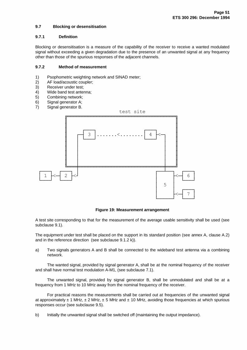
Page 51ETS 300 296: December 1994
9.7 Blocking or desensitisation
9.7.1 Definition
Blocking or desensitisation is a measure of the capability of the receiver to receive a wanted modulatedsignal without exceeding a given degradation due to the presence of an unwanted signal at any frequencyother than those of the spurious responses of the adjacent channels.
9.7.2 Method of measurement
1) Psophometric weighting network and SINAD meter;2) AF load/acoustic coupler;3) Receiver under test;4) Wide band test antenna;5) Combining network;6) Signal generator A;7) Signal generator B.
test site ÉÍÍÍÍÍÍÍÍÍÍÍÍÍÍÍÍÍÍÍÍÍÍÍÍÍÍÍÍÍÍÍÍÍÍÍÍÍ» º º º º º ÚÄÄÄ¿ ÚÄÄÄ¿ º º ÚÄ´ 3 ³.......<........³ 4 Ã<Ä¿ º º ³ ÀÄÄÄÙ ÀÄÄÄÙ ³ º º ³ ³ º º ³ ³ º º ³ ³ º º ³ ³ º º ³ ³ º ÈÍÍÍØÍÍÍÍÍÍÍÍÍÍÍÍÍÍÍÍÍÍÍÍÍÍÍÍÍÍÍÍÍØÍÍͼ ÚÄÄÄ¿ ÚÄÄÄ¿ ³ ÚÄÄÁÄÄ¿ ÚÄÄÄ¿ ³ 1 Ã<Ä´ 2 Ã<Ù ³ Ã<Ä´ 6 ³ ÀÄÄÄÙ ÀÄÄÄÙ ³ ³ ÀÄÄÄÙ ³ 5 ³ ³ ³ ÚÄÄÄ¿ ³ Ã<Ä´ 7 ³ ÀÄÄÄÄÄÙ ÀÄÄÄÙ
Figure 19: Measurement arrangement
A test site corresponding to that for the measurement of the average usable sensitivity shall be used (seesubclause 9.1).
The equipment under test shall be placed on the support in its standard position (see annex A, clause A.2)and in the reference direction (see subclause 9.1.2 k)).
a) Two signals generators A and B shall be connected to the wideband test antenna via a combiningnetwork.
The wanted signal, provided by signal generator A, shall be at the nominal frequency of the receiverand shall have normal test modulation A-M1, (see subclause 7.1).
The unwanted signal, provided by signal generator B, shall be unmodulated and shall be at afrequency from 1 MHz to 10 MHz away from the nominal frequency of the receiver.
For practical reasons the measurements shall be carried out at frequencies of the unwanted signalat approximately ± 1 MHz, ± 2 MHz, ± 5 MHz and ± 10 MHz, avoiding those frequencies at which spuriousresponses occur (see subclause 9.5).
b) Initially the unwanted signal shall be switched off (maintaining the output impedance).
Page 52ETS 300 296: December 1994
The level of the wanted signal from generator A shall be adjusted to the level of the limit of theaverage usable sensitivity expressed as a field strength (see subclauses 5.2.1 and 9.1.4).
Where possible, the receiver volume control shall be adjusted to give at least 50 % of the ratedoutput power, subclause 7.8, or, in the case of stepped volume controls, to the first step thatprovides an output power of at least 50 % of the rated output power. The obtained audio outputlevel shall be noted.
c) The unwanted signal from generator B shall then be switched on.
d) The level of generator B shall be adjusted so that the unwanted signal causes:
- a reduction of 3 dB in the output level of the wanted signal; or- a reduction to 14 dB of the SINAD ratio at the receiver output (with a psophometricfilter), whether or not measured acoustically;
whichever occurs first.
e) The level of the unwanted signal shall be recorded.
f) For each frequency, the blocking or desensitisation shall be expressed as the level in dBµV/m of thefield strength of the unwanted signal at the receiver location.
g) The measurement shall be repeated for all the frequencies defined in step a).
h) The blocking or desensitisation of the equipment under test shall be expressed as the level indBµV/m of the field strength of the unwanted signal, at the receiver location, corresponding to thelowest value recorded in step e).
9.8 Spurious radiations
9.8.1 Definition
Spurious radiations from the receiver are components at any frequency radiated by the equipment and itsantenna.
They are specified as the radiated power of any discrete signal.

Page 53ETS 300 296: December 1994
9.8.2 Method of measurement
test site ÉÍÍÍÍÍÍÍÍÍÍÍÍÍÍÍÍÍÍÍÍÍÍÍÍÍÍÍÍÍÍÍÍÍÍÍÍÍ» º º º º º º º º º ÚÄÄÄ¿ ÚÄÄÄ¿ º º ³ 1 ³.......>........³ 2 ÃÄÄ¿ º º ÀÄÄÄÙ ÀÄÄÄÙ ³ º º ³ º º ³ º º ³ º º ³ º º ³ º ÈÍÍÍÍÍÍÍÍÍÍÍÍÍÍÍÍÍÍÍÍÍÍÍÍÍÍÍÍÍÍÍÍÍØÍÍͼ ³ ÚÄÄÄ¿ ÀÄ>´ 3 ³ ÀÄÄÄÙ1) Receiver under test;2) Test antenna;3) Spectrum analyser or selective voltmeter (test receiver).
Figure 20: Measurement arrangement
a) A test site which fulfils the requirements of the specified frequency range of this measurement shallbe used. The test antenna shall be oriented for vertical polarisation and connected to a spectrumanalyser or a selective voltmeter. The resolution bandwidth of the spectrum analyser or selectivevoltmeter shall be the smallest bandwidth available which is greater than the spectral width of thespurious component being measured. This shall be considered to be achieved when the next highestbandwith causes less than 1 dB increase in amplitude. The conditions used in the measurement shallbe recorded in the test report.
b) The receiver under test shall be placed on the support in its standard position (see annex A,clause A.2). The radiation of any spurious component shall be detected by the test antenna andspectrum analyser or selective voltmeter over the frequency range 30 MHz to 4 GHz. In addition, forequipment operating on frequencies above 470 MHz, measurements shall be repeated over thefrequency range 4 GHz to 12,75 GHz.
The frequency of each spurious component shall be recorded. If the test site is disturbed byradiation coming from outside, this qualitative search may be performed in a screened room with reduceddistance between the receiver and the test antenna.
c) At each frequency at which a component has been detected, the spectrum analyser or selectivevoltmeter shall be tuned and the test antenna shall be raised or lowered through the specified heightrange until the maximum signal level is detected on the spectrum analyser or selective voltmeter.
d) The receiver shall be rotated through 360° around a vertical axis, until higher maximum signal isreceived.
e) The test antenna shall be raised or lowered again through the specified height range until amaximum is obtained. This level shall be recorded.
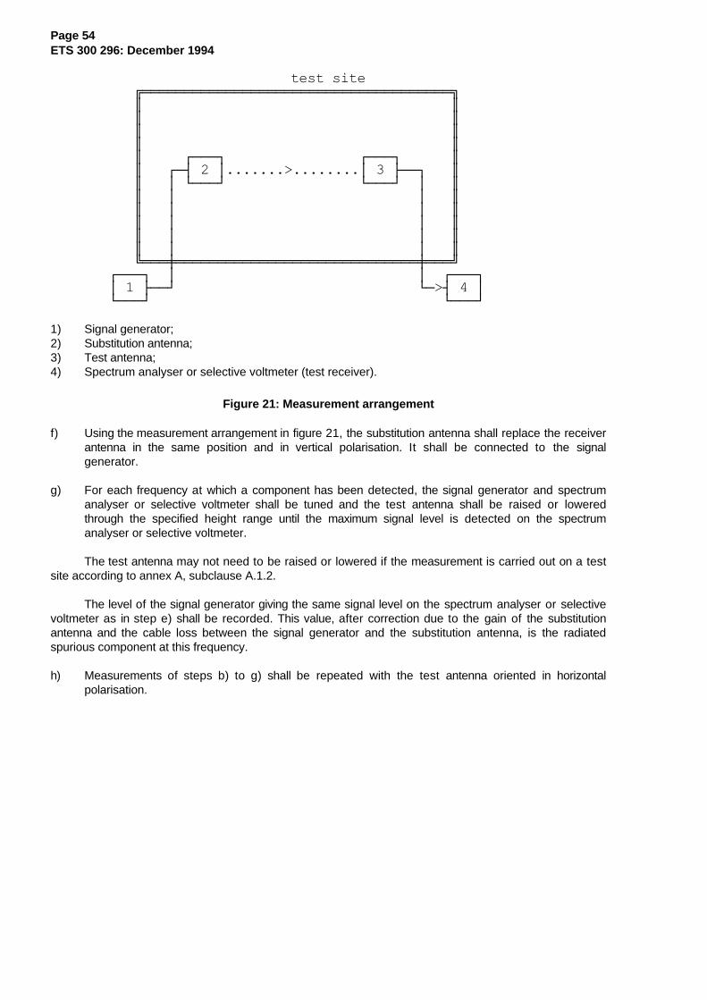
Page 54ETS 300 296: December 1994
test site ÉÍÍÍÍÍÍÍÍÍÍÍÍÍÍÍÍÍÍÍÍÍÍÍÍÍÍÍÍÍÍÍÍÍÍÍÍÍ» º º º º º º º º º ÚÄÄÄ¿ ÚÄÄÄ¿ º º ÚÄ´ 2 ³.......>........³ 3 ÃÄÄ¿ º º ³ ÀÄÄÄÙ ÀÄÄÄÙ ³ º º ³ ³ º º ³ ³ º º ³ ³ º º ³ ³ º º ³ ³ º ÈÍÍÍØÍÍÍÍÍÍÍÍÍÍÍÍÍÍÍÍÍÍÍÍÍÍÍÍÍÍÍÍÍØÍÍͼ ÚÄÄÄ¿ ³ ³ ÚÄÄÄ¿ ³ 1 ÃÄÄÙ ÀÄ>´ 4 ³ ÀÄÄÄÙ ÀÄÄÄÙ
1) Signal generator;2) Substitution antenna;3) Test antenna;4) Spectrum analyser or selective voltmeter (test receiver).
Figure 21: Measurement arrangement
f) Using the measurement arrangement in figure 21, the substitution antenna shall replace the receiverantenna in the same position and in vertical polarisation. It shall be connected to the signalgenerator.
g) For each frequency at which a component has been detected, the signal generator and spectrumanalyser or selective voltmeter shall be tuned and the test antenna shall be raised or loweredthrough the specified height range until the maximum signal level is detected on the spectrumanalyser or selective voltmeter.
The test antenna may not need to be raised or lowered if the measurement is carried out on a testsite according to annex A, subclause A.1.2.
The level of the signal generator giving the same signal level on the spectrum analyser or selectivevoltmeter as in step e) shall be recorded. This value, after correction due to the gain of the substitutionantenna and the cable loss between the signal generator and the substitution antenna, is the radiatedspurious component at this frequency.
h) Measurements of steps b) to g) shall be repeated with the test antenna oriented in horizontalpolarisation.
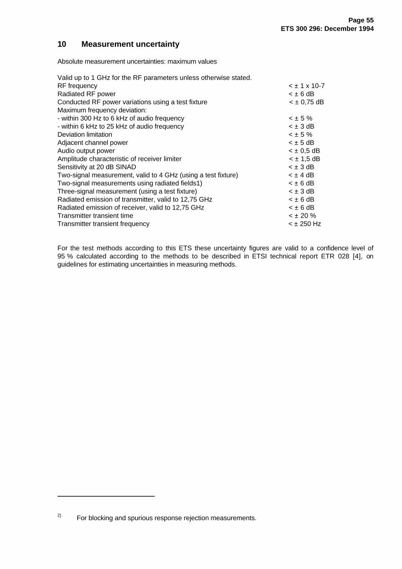
Page 55ETS 300 296: December 1994
10 Measurement uncertainty
Absolute measurement uncertainties: maximum values
Valid up to 1 GHz for the RF parameters unless otherwise stated.RF frequency < ± 1 x 10⁻⁷Radiated RF power < ± 6 dBConducted RF power variations using a test fixture < ± 0,75 dBMaximum frequency deviation:- within 300 Hz to 6 kHz of audio frequency < ± 5 %- within 6 kHz to 25 kHz of audio frequency < ± 3 dBDeviation limitation < ± 5 %Adjacent channel power < ± 5 dBAudio output power < ± 0,5 dBAmplitude characteristic of receiver limiter < ± 1,5 dBSensitivity at 20 dB SINAD < ± 3 dBTwo-signal measurement, valid to 4 GHz (using a test fixture) < ± 4 dBTwo-signal measurements using radiated fields1) < ± 6 dBThree-signal measurement (using a test fixture) < ± 3 dBRadiated emission of transmitter, valid to 12,75 GHz < ± 6 dBRadiated emission of receiver, valid to 12,75 GHz < ± 6 dBTransmitter transient time < ± 20 %Transmitter transient frequency < ± 250 Hz
For the test methods according to this ETS these uncertainty figures are valid to a confidence level of95 % calculated according to the methods to be described in ETSI technical report ETR 028 [4], onguidelines for estimating uncertainties in measuring methods.
2) For blocking and spurious response rejection measurements.

Page 56ETS 300 296: December 1994
Annex A (normative): Radiated measurements
A.1 Test sites and general arrangements for measurements involving the use ofradiated fields
Any of the following four test sites may be used.
A.1.1 Open air test site
A.1.1.1 Description
The term "open air" shall be understood from a electromagnetic point of view. Such a test site may bereally in open air or alternatively with walls and ceiling transparent to the radio waves at the frequenciesconsidered.
An open air test site can be used to perform the measurements using the radiated measurement methodsdescribed in clauses 8 and 9. Absolute or relative measurements can be performed on transmitters or onreceivers; absolute measurements of field strength require a calibration of the test site.
Sufficient precautions shall be taken to ensure that reflections from extraneous objects adjacent to the sitedo not degrade the measurement results, in particular:
- no extraneous conducting objects having any dimension in excess of a quarter wavelength of thehighest frequency tested shall be in the immediate vicinity of the site;
- all cables shall be as short as possible; as much of the cables as possible shall be on the groundplane or preferably below; and the low impedance cables shall be screened.
ÚÄÄÄ¿ ............³ 2 ÃÄÄ¿ . ÀÄÂÄÙ ³ . ³ ³ ÚÄÄÄ¿ . Specified ³ ³ ³ 1 ³ ..... height ³ ³ ÀÄÂÄÙ range ³ ³ ³ 1 to 4 m ³ ³ ³ ³ ³ ³ 1,5 m ³ ³ ³ ³ ³ ³ Ground plane ³ ³±±±±±±±±±±±±±±±±±±±±±±±±±±±±±±±±±±±±±±±±±±±±±³±±±±±±±±±±±±± ÚÄÄÄ¿ ³ ÚÄÄÄ¿ ³ 4 ³ ÀÄ´ 3 ³ ³ ÃÄÄÄÄ´ ³ ÀÄÄÄÙ ÀÄÄÄÙ
1) Equipment under test;2) Test antenna;3) High pass filter (necessary for strong fundamental Tx radiation);4) Spectrum analyser or measuring receiver.
Figure A.1: Measuring arrangement
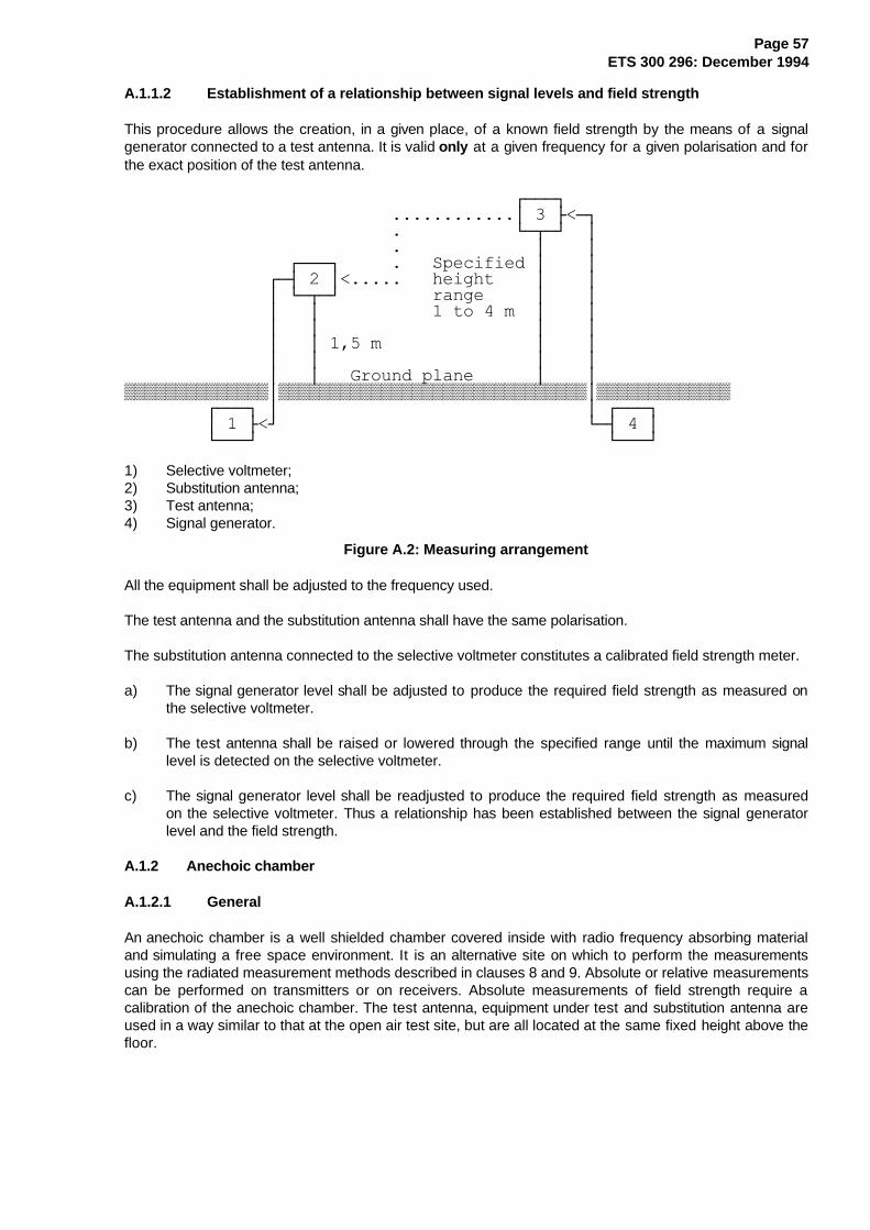
Page 57ETS 300 296: December 1994
A.1.1.2 Establishment of a relationship between signal levels and field strength
This procedure allows the creation, in a given place, of a known field strength by the means of a signalgenerator connected to a test antenna. It is valid only at a given frequency for a given polarisation and forthe exact position of the test antenna.
ÚÄÄÄ¿ ............³ 3 Ã<Ä¿ . ÀÄÂÄÙ ³ . ³ ³ ÚÄÄÄ¿ . Specified ³ ³ ÚÄ´ 2 ³<..... height ³ ³ ³ ÀÄÂÄÙ range ³ ³ ³ ³ 1 to 4 m ³ ³ ³ ³ ³ ³ ³ ³ 1,5 m ³ ³ ³ ³ ³ ³ ³ ³ Ground plane ³ ³±±±±±±±±±±±±±±³±±±±±±±±±±±±±±±±±±±±±±±±±±±±±±³±±±±±±±±±±±±± ÚÄÄÄ¿ ³ ³ ÚÄÄÄ¿ ³ 1 Ã<Ù ÀÄ´ 4 ³ ÀÄÄÄÙ ÀÄÄÄÙ
1) Selective voltmeter;2) Substitution antenna;3) Test antenna;4) Signal generator.
Figure A.2: Measuring arrangement
All the equipment shall be adjusted to the frequency used.
The test antenna and the substitution antenna shall have the same polarisation.
The substitution antenna connected to the selective voltmeter constitutes a calibrated field strength meter.
a) The signal generator level shall be adjusted to produce the required field strength as measured onthe selective voltmeter.
b) The test antenna shall be raised or lowered through the specified range until the maximum signallevel is detected on the selective voltmeter.
c) The signal generator level shall be readjusted to produce the required field strength as measuredon the selective voltmeter. Thus a relationship has been established between the signal generatorlevel and the field strength.
A.1.2 Anechoic chamber
A.1.2.1 General
An anechoic chamber is a well shielded chamber covered inside with radio frequency absorbing materialand simulating a free space environment. It is an alternative site on which to perform the measurementsusing the radiated measurement methods described in clauses 8 and 9. Absolute or relative measurementscan be performed on transmitters or on receivers. Absolute measurements of field strength require acalibration of the anechoic chamber. The test antenna, equipment under test and substitution antenna areused in a way similar to that at the open air test site, but are all located at the same fixed height above thefloor.

Page 58ETS 300 296: December 1994
A.1.2.2 Description
An anechoic chamber should meet the requirements for shielding loss and wall return loss as shown infigure A.3. Figure A.4 shows an example of the construction of an anechoic chamber having a base area of5 m by 10 m and a height of 5 m. The ceiling and walls are coated with pyramidally formed absorbersapproximately 1 m high. The base is covered with special absorbers which form the floor. The availableinternal dimensions of the chamber are 3 m x 8 m x 3 m, so that a maximum measuring distance of 5 m inthe middle axis of this chamber is available (see Bibliography). The floor absorbers reject floor reflectionsso that the antenna height need not be changed. Anechoic chambers of other dimensions may be used.
At 100 MHz the measuring distance can be extended up to a maximum of 2 wavelengths.
A.1.2.3 Influence of parasitic reflections
For free-space propagation in the far field the relationship of the field strength E and the distance R isgiven by E = Eo (Ro/R), where Eo is the reference field strength and Ro is the reference distance. Thisrelationship allows relative measurements to be made as all constants are eliminated within the ratio andneither cable attenuation nor antenna mismatch or antenna dimensions are of importance.
If the logarithm of the foregoing equation is used, the deviation from the ideal curve can be easily seenbecause the ideal correlation of field strength and distance appears as a straight line. The deviationsoccurring in practice are then clearly visible. This indirect method shows quickly and easily anydisturbances due to reflections and is far less difficult than the direct measurement of reflectionattenuation.
With an anechoic chamber of the dimensions given above at low frequencies below 100 MHz there are nofar field conditions, but the wall reflections are stronger, so that careful calibration is necessary. In themedium frequency range from 100 MHz to 1 GHz the dependence of the field strength to the distancemeets the expectations very well. Above 1 GHz, because more reflections will occur, the dependence ofthe field strength to the distance will not correlate so closely.
A.1.2.4 Mode of use
The mode of use is the same as for an open air test site, the only difference being that the test antennadoes not need to be raised and lowered whilst searching for a maximum, which simplifies the method ofmeasurement.
0
10
20
30
40
50
60
70
80
90
100
110
10 k 100 k 1 M 10 M 30 M 100 M 300 M 1 G 4 G 10 G f (Hz)
AAAAAAAAAAAAAAAAAAAAAAAAAAAAAAAAAAAA
AAAAAAAAAAAAAAAAAAAAAAAAAAAAAAAAAAAA
AAAAAAAAAAAAAAAAAAAAAAAAAAAAAAAAAAAA
AAAAAAAAAAAAAAAAAAAAAAAAAAAAAAAAAAAA
AAAAAAAAAAAAAAAAAAAAAAAAAAAAAAAAAAAA
AAAAAAAAAAAAAAAAAAAAAAAAAAAAAAAAAAAA
AAAAAAAAAAAAAAAAAAAAAAAAAAAAAAAAAAAA
AAAAAAAAAAAAAAAAAAAAAAAAAAAAAAAAAAAA
AAAAAAAAAAAAAAAAAAAAAAAAAAAAAAAAAAAA
AAAAAAAAA
AAAAAAAAAAAAAAAA
AAAAAAAAAAAAAAAAAAAA
AAAAAAAA
AAAA
a (dB)
Minimum limit for the sheilding loss
Limit of the return loss
Figure A.3: Specification for shielding and reflections
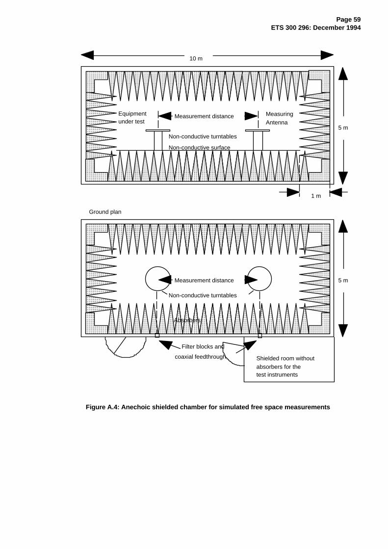
Page 59ETS 300 296: December 1994
AAAAAAAAAAAAAAAAAAAAA
AAAAAAAAAAAAAAAAAAAAA
AAAAAAAAAAAAAAAAAAAAA
AAAAAAAAAAAAAA
AAAAAAAAAAAAAAAAAAAAA
AAAAAAAAAAAAAAAAAAAAA
AAAAAAAAAAAAAA
AAAAAAAAAAAAAAAAAAAAA
AAAAAAAAAAAAAA
AAAAAAAAAAAAAAAAAAAAA
AAAAAAAAAAAAAAAAAAAAA
AAAAAAAAAAAAAAAAAAAAA
AAAAAAAAAAAAAAAAAAAAA
AAAAAAAAAAAAAA
AAAAAAAAAAAAAAAAAAAAA
AAAAAAAAAAAAAAAAAAAAA
AAAAAAAAAAAAAA
AAAAAAAAAAAAAAAAAAAAA
AAAAAAAAAAAAAAAAAAAAA
AAAAAAAAAAAAAAAAAAAAA
AAAAAAAAAAAAAAAAAAAAA
AAAAAAAAAAAAAA
AAAAAAAAAAAAAAAAAAAAA
AAAAAAAAAAAAAAAAAAAAA
AAAAAAAAAAAAAAAAAAAAA
AAAAAAAAAAAAAAAAAAAAA
AAAAAAAAAAAAAA
AAAAAAAAAAAAAAAAAAAAA
AAAAAAAAAAAAAAAAAAAAA
AAAAAAAAAAAAAA
AAAAAAAAAAAAAAAAAAAAA
AAAAAAAAAAAAAA
AAAAAAAA
AAAAAA
AAAAAAAAAAAA
AAAAAAAAA
AAAAAAAAAAAA
AAAAAAAAA
AAAAAAAAAAAA
AAAAAAAAA
AAAAAAAAAAAA
AAAAAAAAA
AAAAAAAA
AAAAAA
AAAAAAAAAAAA
AAAAAAAAA
AAAAAAAAAAAA
AAAAAAAAA
AAAAAAAA
AAAAAA
AAAAAAAAAAAA
AAAAAAAAA
AAAAAAAAAAAA
AAAAAAAAA
AAAAAAAAAAAA
AAAAAAAAA
AAAAAAAAAAAA
AAAAAAAAA
AAAAAAAA
AAAAAA
AAAAAAAAAAAA
AAAAAAAAA
AAAAAAAAAAAA
AAAAAAAAA
AAAAAAAAAAAAAA
AAAAAAAAAAAAAAAAAAAAA
AAAAAAAAAAAAAAAAAAAAA
AAAAAAAAAAAAAA
AAAAAAAAAAAAAAAAAAAAA
AAAAAAAAAAAAAAAAAAAAA
AAAAAAAAAAAAAA
AAAAAAAAAAAAAAAAAAAAA
AAAAAAAAAAAAAA
AAAAAAAAAAAAAAAAAAAAA
AAAAAAAAAAAAAAAAAAAAA
AAAAAAAAAAAAAAAAAAAAA
AAAAAAAAAAAAAAAAAAAAA
AAAAAAAAAAAAAA
AAAAAAAAAAAAAAAAAAAAA
AAAAAAAAAAAAAAAAAAAAA
AAAAAAAAAAAAAA
AAAAAAAAAAAAAAAAAAAAA
AAAAAAAAAAAAAAAAAAAAA
AAAAAAAAAAAAAAAAAAAAA
AAAAAAAAAAAAAAAAAAAAA
AAAAAAAAAAAAAA
AAAAAAAAAAAAAAAAAAAAA
AAAAAAAAAAAAAAAAAAAAA
AAAAAAAAAAAAAAAAAAAAA
AAAAAAAAAAAAAAAAAAAAA
AAAAAAAAAAAAAA
AAAAAAAAAAAAAAAAAAAAA
AAAAAAAAAAAAAAAAAAAAA
AAAAAAAAAAAAAAAAAAAAA
AAAAAAAAAAAAAAAAAAAAA
AAAAAAAAAAAAAA
AAAAAAAAAAAAAAAAAAAA
AAAAA
AAAAAAAAAAAAAAAAAAAA
AAAAA
AAAAAAAAAAAAAAAAAAAA
AAAAA
AAAAAAAAAAAAAAAAAAAA
AAAAA
AAAAAAAAAAAAAAAAAA
AAAAAAAAAAAAAAAAAA
AAAAAAAAAAAAAAAAAA
AAAAAAAAAAAA
AAAAAAAAAAAAAAAAAA
AAAAAAAAAAAAAAAAAA
AAAAAAAAAAAA
AAAAAAAAAAAAAAAAAA
AAAAAAAAAAAA
AAAAAAAAAAAAAAAAAA
AAAAAAAAAAAAAAAAAA
AAAAAAAAAAAAAAAAAA
AAAAAAAAAAAAAAAAAA
AAAAAAAAAAAA
AAAAAAAAAAAAAAAAAA
AAAAAAAAAAAAAAAAAA
AAAAAAAAAAAA
AAAAAAAAAAAAAAAAAA
AAAAAAAAAAAAAAAAAA
AAAAAAAAAAAAAAAAAA
AAAAAAAAAAAAAAAAAA
AAAAAAAAAAAA
AAAAAAAAAAAAAAAAAA
AAAAAAAAAAAAAAAAAA
AAAAAAAAAAAAAAAAAA
AAAAAAAAAAAAAAAAAA
AAAAAAAAAAAA
AAAAAAAAAAAAAAAAAA
AAAAAAAAAAAAAAAAAA
AAAAAAAAAAAA
AAAAAAAAAAAAAAAAAA
AAAAAAAAAAAA
AAAAAAAAAAAA
AAAAAAAAA
AAAAAAAAAAAA
AAAAAAAAA
AAAAAAAAAAAA
AAAAAAAAA
AAAAAAAA
AAAAAA
AAAAAAAAAAAA
AAAAAAAAA
AAAAAAAAAAAA
AAAAAAAAA
AAAAAAAA
AAAAAA
AAAAAAAAAAAA
AAAAAAAAA
AAAAAAAAAAAA
AAAAAAAAA
AAAAAAAAAAAA
AAAAAAAAA
AAAAAAAAAAAA
AAAAAAAAA
AAAAAAAA
AAAAAA
AAAAAAAAAAAA
AAAAAAAAA
AAAAAAAAAAAA
AAAAAAAAA
AAAAAAAA
AAAAAA
AAAAAAAAAAAA
AAAAAAAAA
AAAAAAAAAAAAAA
AAAAAAAAAAAAAAAAAAAAA
AAAAAAAAAAAAAAAAAAAAA
AAAAAAAAAAAAAA
AAAAAAAAAAAAAAAAAAAAA
AAAAAAAAAAAAAAAAAAAAA
AAAAAAAAAAAAAA
AAAAAAAAAAAAAAAAAAAAA
AAAAAAAAAAAAAA
AAAAAAAAAAAAAAAAAAAAA
AAAAAAAAAAAAAAAAAAAAA
AAAAAAAAAAAAAAAAAAAAA
AAAAAAAAAAAAAAAAAAAAA
AAAAAAAAAAAAAA
AAAAAAAAAAAAAAAAAAAAA
AAAAAAAAAAAAAAAAAAAAA
AAAAAAAAAAAAAA
AAAAAAAAAAAAAAAAAAAAA
AAAAAAAAAAAAAAAAAAAAA
AAAAAAAAAAAAAAAAAAAAA
AAAAAAAAAAAAAAAAAAAAA
AAAAAAAAAAAAAA
AAAAAAAAAAAAAAAAAAAAA
AAAAAAAAAAAAAAAAAAAAA
AAAAAAAAAAAAAAAAAAAAA
AAAAAAAAAAAAAAAAAAAAA
AAAAAAAAAAAAAA
AAAAAAAAAAAAAAAAAAAAA
AAAAAAAAAAAAAAAAAAAAA
AAAAAAAAAAAAAAAAAAAAA
AAAAAAAAAAAAAAAAAAAAA
AAAAAAAAAAAAAA
AAAAAAAAAAAAAAAAAAAA
AAAAA
AAAAAAAAAAAAAAAAAAAA
AAAAA
AAAAAAAAAAAAAAAAAAAA
AAAAA
AAAAAAAAAAAAAAAAAAAA
AAAAA
10 m
5 m
1 m
Equipmentunder test
Non-conductive turntables
Non-conductive surface
Measurement distance
Measurement distance
Non-conductive turntables
MeasuringAntenna
Filter blocks and
coaxial feedthrough Shielded room withoutabsorbers for thetest instruments
5 m
Ground plan
Absorbers
Figure A.4: Anechoic shielded chamber for simulated free space measurements
Page 60ETS 300 296: December 1994
A.1.3 Stripline arrangement
A.1.3.1 General
The stripline arrangement is a RF coupling device for coupling the integral antenna of an equipment to a50 Ω radio frequency terminal. This allows the radiated measurements to be performed without an openair test site but in a restricted frequency range. Absolute or relative measurements can be performed;absolute measurements require a calibration of the stripline arrangement.
A.1.3.2 Description
The stripline is made of three highly conductive sheets forming part of a transmission line which allows theequipment under test to be placed within a known electric field. They must be sufficiently rigid to supportthe equipment under test.
Two examples of stripline characteristics are given below:
IEC 489-3 App. J FTZ No 512 TB 9Useful frequency range: MHz 1 to 200 0,1 to 4 000Equipment size limits: length 200 mm 1 200 mm(antenna included): width 200 mm 1 200 mm
height 250 mm 400 mm
A.1.3.3 Calibration
The aim of calibration is to establish at any frequency a relationship between the voltage applied by thesignal generator and the field strength at the designated test area inside the stripline.
A.1.3.4 Mode of use
The stripline arrangement may be used for all radiated measurements within its calibrated frequencyrange.
The method of measurement is the same as the method using a open air test site with the followingchange. The stripline arrangement input socket is used instead of the test antenna.
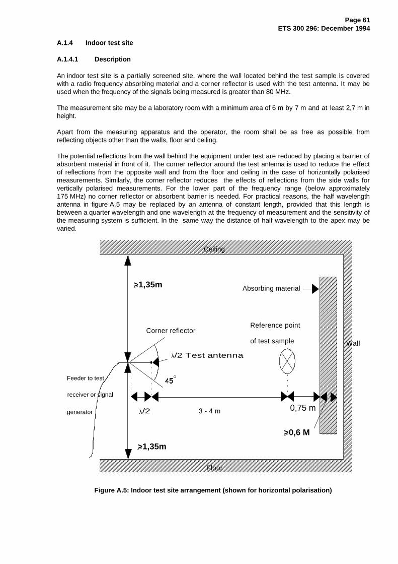
Page 61ETS 300 296: December 1994
A.1.4 Indoor test site
A.1.4.1 Description
An indoor test site is a partially screened site, where the wall located behind the test sample is coveredwith a radio frequency absorbing material and a corner reflector is used with the test antenna. It may beused when the frequency of the signals being measured is greater than 80 MHz.
The measurement site may be a laboratory room with a minimum area of 6 m by 7 m and at least 2,7 m inheight.
Apart from the measuring apparatus and the operator, the room shall be as free as possible fromreflecting objects other than the walls, floor and ceiling.
The potential reflections from the wall behind the equipment under test are reduced by placing a barrier ofabsorbent material in front of it. The corner reflector around the test antenna is used to reduce the effectof reflections from the opposite wall and from the floor and ceiling in the case of horizontally polarisedmeasurements. Similarly, the corner reflector reduces the effects of reflections from the side walls forvertically polarised measurements. For the lower part of the frequency range (below approximately175 MHz) no corner reflector or absorbent barrier is needed. For practical reasons, the half wavelengthantenna in figure A.5 may be replaced by an antenna of constant length, provided that this length isbetween a quarter wavelength and one wavelength at the frequency of measurement and the sensitivity ofthe measuring system is sufficient. In the same way the distance of half wavelength to the apex may bevaried.
AAAAAAAAAAAAAAAA
AAAAAAAAAAAAAAAA
AAAAAAAAAAAAAAAA
AAAAAAAAAAAAAAAA
AAAAAAAAAAAAAAAA
AAAAAAAAAAAAAAAA
AAAAAAAAAAAAAAAA
AAAAAAAAAAAAAAAA
AAAAAAAAAAAAAAAA
AAAAAAAAAAAAAAAA
AAAAAAAAAAAAAAAA
AAAAAAAAAAAA
AAAAAAAAAAAAAAAAAAAAAAAAAAAAAAAAAAAAAAAAAAAAAAAAAAAAAAAAAAAAAAAAAAAAAAAAAAAAAAAAAAAAAAAAAA
AAAAAAAAAAAAAAAA
AAAAAAAAAAAAAAAA
AAAAAAAAAAAAAAAA
AAAAAAAAAAAAAAAA
AAAAAAAAAAAAAAAA
AAAAAAAAAAAAAAAA
AAAAAAAAAAAAAAAA
AAAAAAAAAAAAAAAA
AAAAAAAAAAAAAAAA
AAAAAAAAAAAAAAAA
AAAAAAAAAAAAAAAA
AAAAAAAAAAAA
AAAAAAAAAAAAAAAAAAAAAAAAAAAAAAAAAAAAAAAAAAAAAAAAAAAAAAAAAAAAAAAAAAAAAAAAAAAAAAAAAAAAAAAAAAAAAAAAAAAAAAAAAAAAAAAAAAAAAAAA
Ceiling
Absorbing material
Reference point
of test sample
3 - 4 mλ/2
Corner reflector
Feeder to test
receiver or signal
generator
Floor
Wall
λ/2 Test antenna
>1,35m
>1,35m
>0,6 M
0,75 m
Figure A.5: Indoor test site arrangement (shown for horizontal polarisation)
Page 62ETS 300 296: December 1994
A.1.4.2 Test for parasitic reflections
To ensure that errors are not caused by the propagation path approaching the point at which phasecancellation between direct and the remaining reflected signals occurs, the substitution antenna shall bemoved through a distance of ± 10 cm in the direction of the test antenna as well as in the two directionsperpendicular to this first direction.
If these changes of distance cause a signal change of greater than 2 dB, the test sample should berepositioned until a change of less than 2 dB is obtained.
A.1.4.3 Mode of use
The mode of use is the same as for an open air test site, the only difference being that the test antennadoes not need to be raised and lowered whilst searching for a maximum, which simplifies the method ofmeasurement.
A.2 Standard position
The standard position in all test sites, except the stripline arrangement, for equipment which is not intendedto be worn on a person, including hand-held equipment, shall be on a non conducting support, height 1,5 m,capable of rotating about a vertical axis through the equipment. The standard position of the equipmentshall be the following:
a) for equipment with an internal antenna, it shall be placed in the position closest to normal use asdeclared by the manufacturer;
b) for equipment with a rigid external antenna, the antenna shall be vertical;
c) for equipment with a non-rigid external antenna, the antenna shall be extended vertically upwards bya non-conducting support.
Equipment which is intended to be worn on a person may be tested using a simulated man as support.
The simulated man comprises a rotatable acrylic tube filled with salt water, placed on the ground.
The container shall have the following dimensions:
- height 1,7 ± 0,1 m;
- inside diameter 300 ± 5 mm;
- sidewall thickness 5 ± 0,5 mm.
The container shall be filled with a salt (NaCl) solution of 1,5 g per litre of distilled water.
The equipment shall be fixed to the surface of the simulated man, at the appropriate height for theequipment.
NOTE: To reduce the weight of the simulated man it may be possible to use an alternative tubewhich has a hollow centre of 220 mm maximum diameter.
In the stripline arrangement the equipment under test or the substitution antenna is placed in thedesignated test area in the normal operational position, relative to the applied field, on a pedestal made ofa low dielectric material (dielectric constant less than 2).
Page 63ETS 300 296: December 1994
A.3 Acoustic coupler
A.3.1 General
When radiation measurements are performed, on the receiver, the audio output voltage should beconducted from the receiver to the measuring equipment, without perturbing the field near the receiver.
This perturbation can be minimized by using wires with high resistivity associated to a test equipment witha high input impedance (IEC 489-3 appendix F).
When this situation is not applicable, an acoustic coupler shall be used.
NOTE: When using this acoustic coupler care should be exercised that possible ambient noisedoes not influence the test result.
A.3.2 Description
The acoustic coupler comprises of, a plastic funnel, an acoustic pipe and a microphone with a suitableamplifier.
- The acoustic pipe shall be long enough (e.g. 2 m) to reach from the equipment under test to themicrophone which is located in a position that will not disturb the RF field. The acoustic pipe shallhave an inner diameter of about 6 mm and a wall thickness of about 1,5 mm and should besufficiently flexible to allow the platform to rotate.
- The plastic funnel shall have a diameter appropriate to the size of the loudspeaker in the equipmentunder test, with soft foam rubber glued to its edge, it shall be fitted to one end of the acoustic pipeand the microphone shall be fitted to the other end. It is very important to fix the centre of the funnelin a reproducible position relative to the equipment under test, since the position of the centre has astrong influence on the frequency response that will be measured. This can be achieved by placingthe equipment in a close fitting acoustic mounting jig, supplied by the manufacturer, of which thefunnel is an integral part.
- The microphone shall have a response characteristic flat within 1 dB over a frequency range of50 Hz to 20 kHz, a linear dynamic range of at least 50 dB. The sensitivity of the microphone and thereceiver audio output level shall be suitable to measure a signal to noise ratio of at least 40 dB atthe nominal audio output level of the equipment under test. Its size should be sufficiently small tocouple to the acoustic pipe.
- The frequency correcting network shall correct the frequency response of the acoustic coupler sothat the acoustic SINAD measurement is valid, IEC 489-3 appendix F.
A.3.3 Calibration
The aim of the calibration of the acoustic coupler is to determine the acoustic SINAD ratio which isequivalent to the SINAD ratio at the receiver output.
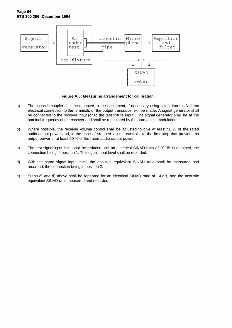
Page 64ETS 300 296: December 1994
ÚÄÄÄÄÄÄÄÄÄÄÄÄ¿ ³ ÚÄÄÄÄÄ¿ ³ ÚÄÄÄÄÄÄÄÄÄ¿ ³ ³ ³ ³ ÚÄÄÄÄÄ¿ ÚÄÄÄÄÄÄÄÄÄ¿ ³ Signal ³ ³ ³ Rx ÿ ³ acoustic ³Micro³ ³Amplifier³ ³ ÃÄ>´ ³under³ÆÍØÍÍÍÍÍÍÍÍÍÍ͵phoneÃÄÄ>´ and ³ ³generator³ ³ ³test ÃÙ ³ pipe ³ ³ ³ filter ³ ÀÄÄÄÄÄÄÄÄÄÙ ³ ³ ÃÄÄÅÄÄÄ¿ ÀÄÄÄÄÄÙ ÀÄÄÄÄÂÄÄÄÄÙ ³ ÀÄÄÄÄÄÙ ³ ³ ³ ³Test fixture³ ÀÄÄÄÄÄÄÄÄÄÄÄÄ> <ÄÄÄÄÄÄÄÙ ÀÄÄÄÄÄÄÄÄÄÄÄÄÙ 1 ³ 2 ÚÄÄÄÄÁÄÄÄÄ¿ ³ SINAD ³ ³ ³ ³ meter ³ ÀÄÄÄÄÄÄÄÄÄÙ
Figure A.6: Measuring arrangement for calibration
a) The acoustic coupler shall be mounted to the equipment, if necessary using a test fixture. A directelectrical connection to the terminals of the output transducer will be made. A signal generator shallbe connected to the receiver input (or to the test fixture input). The signal generator shall be at thenominal frequency of the receiver and shall be modulated by the normal test modulation.
b) Where possible, the receiver volume control shall be adjusted to give at least 50 % of the ratedaudio output power and, in the case of stepped volume controls, to the first step that provides anoutput power of at least 50 % of the rated audio output power.
c) The test signal input level shall be reduced until an electrical SINAD ratio of 20 dB is obtained, theconnection being in position 1. The signal input level shall be recorded.
d) With the same signal input level, the acoustic equivalent SINAD ratio shall be measured andrecorded, the connection being in position 2.
e) Steps c) and d) above shall be repeated for an electrical SINAD ratio of 14 dB, and the acousticequivalent SINAD ratio measured and recorded.

Page 65ETS 300 296: December 1994
A.4 Test antenna
When the test site is used for radiation measurements the test antenna is used to detect the field fromboth the test sample and the substitution antenna. When the test site is used for the measurement ofreceiver characteristics the antenna is used as a transmitting antenna. This antenna is mounted on asupport capable of allowing the antenna to be used in either horizontal or vertical polarisation and for theheight of its centre above the ground to be varied over the specified range. Preferably test antennas withpronounced directivity should be used. The size of the test antenna along the measurement axis shall notexceed 20 % of the measuring distance.
A.5 Substitution antenna
The substitution antenna is used to replace the equipment under test. For measurements below 1 GHz thesubstitution antenna shall be a half wavelength dipole resonant at the frequency under consideration, or ashortened dipole, calibrated to the half wavelength dipole. For measurements between 1 and 4 GHz eithera half wavelength dipole or a horn radiator may be used. For measurements above 4 GHz a horn radiatorshall be used. The centre of this antenna shall coincide with the reference point of the test sample it hasreplaced. This reference point shall be the volume centre of the sample when its antenna is mounted insidethe cabinet, or the point where an external antenna is connected to the cabinet.
The distance between the lower extremity of the dipole and the ground shall be at least 30 cm.
NOTE: The gain of a horn antenna is generally expressed relative to an isotropic radiator.
A.6 Test fixture
A.6.1 Description
The test fixture is a radio frequency coupling device associated with an integral antenna equipment forcoupling the integral antenna to a 50 Ω radio frequency terminal at the working frequencies of theequipment under test. This allows certain measurements to be performed using the conductedmeasurement methods. Only relative measurements may be performed and only those at or nearfrequencies for which the test fixture has been calibrated.
In addition, the test fixture shall provide:
a) a connection to an external power supply;b) an audio interface either by direct connection or by an acoustic coupler.
The test fixture normally shall be provided by the manufacturer.
The performance characteristics of the test fixture shall be approved by the testing laboratory and shallconform to the following basic parameters:
a) the coupling loss shall not be greater than 30 dB;b) a coupling loss variation over the frequency range used in the measurement which does
not exceed 2 dB;c) circuitry associated with the RF coupling shall contain no active or non linear devices;d) the VSWR at the 50 Ω socket shall not be greater than 1,5 over the frequency range of
the measurements;e) the coupling loss shall be independent of the position of the test fixture and be
unaffected by the proximity of surrounding objects or people. The coupling loss shall bereproducible when the equipment under test is removed and replaced;
f) the coupling loss shall remain substantially constant when the environmental conditions are varied.
The characteristics and calibration shall be included in the test report.

Page 66ETS 300 296: December 1994
A.6.2 Calibration
The calibration of the test fixture establishes a relationship between the output of the signal generator andthe field strength applied to the equipment inside the test fixture.
The calibration is valid only at a given frequency and for a given polarisation of the reference field.
1) AF load/acoustic coupler;2) Distortion factor/audio level meter and psophometric filter.
ÚÄÄÄÄÄÄÄÄÄÄÄÄÄÄ¿ÚÄÄÄÄÄÄÄÄÄÄ¿ ³ ÚÄÄÄÄÄÄÄÄÄÄ¿ ³ ÚÄÄÄÄÄÄÄÄ¿ ÚÄÄÄÄÄÄÄÄÄÄÄÄ¿³ Signal ³ ³ ³ Receiver ³ ³ ³ ³ ³ ³³ Ã>´ ³ under ³ Ã>´ 1 ÃÄÄ>´ 2 ³³ generator³ ³ ³ test ³ ³ ³ ³ ³ ³ÀÄÄÄÄÄÄÄÄÄÄÙ ³ ÀÄÄÄÄÄÄÄÄÄÄÙ ³ ÀÄÄÄÄÄÄÄÄÙ ÀÄÄÄÄÄÄÄÄÄÄÄÄÙ ³ Test fixture ³ ÀÄÄÄÄÄÄÄÄÄÄÄÄÄÄÙ
Figure A.7: Measuring arrangement for calibration
a) Using the method described in subclause 9.1, measure the sensitivity expressed as fieldstrength, and note the value of this field strength in dBmV/m and the polarisation used.
b) The receiver is now placed in the test fixture which is connected to the signal generator. Thelevel of the signal generator producing a SINAD of 20 dB shall be noted.
c) The calibration of the test fixture is thus the linear relationship between the field strength indBmV/m and the signal generator level in dBmV emf.
A.6.3 Mode of use
The test fixture may be used to facilitate some of the measurements in clauses 8 and 9 on equipment withan integral antenna.
It is used in the radiated carrier power and usable sensitivity expressed as a field strength measurementsin clauses 8 and 9 to enable a measurement to be made under extreme test conditions.
For the transmitter measurements calibration is not required.
For the receiver measurements calibration is necessary.
To apply the specified wanted signal level expressed in field strength, convert it into the signal generatorlevel (emf) using the calibration of the test fixture. Apply this value with the signal generator.

Page 67ETS 300 296: December 1994
A.7 Bibliography
1) IEC Publication 489-3 Second edition (1988) appendix F pages 130 to 133.
2) IEC Publication 489-3 Second edition (1988) appendix J pages 156 to 164.
3) Construction of a Stripline. Technical Report FTZ No 512 TB 9.
4) Ketterling, H-P: Verification of the performance of fully and semi-anechoicchambers for radiation measurements and susceptibility/immunity testing, 1991,Leatherhead/Surrey.
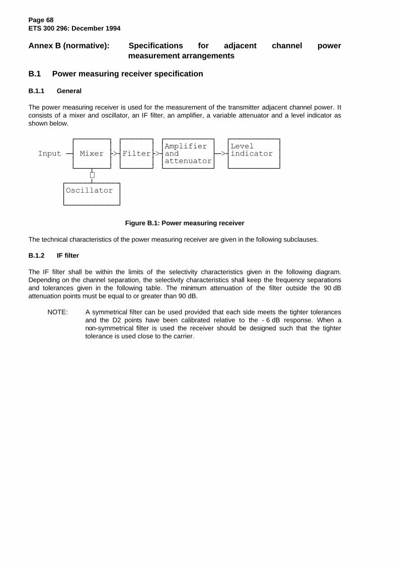
Page 68ETS 300 296: December 1994
Annex B (normative): Specifications for adjacent channel powermeasurement arrangements
B.1 Power measuring receiver specification
B.1.1 General
The power measuring receiver is used for the measurement of the transmitter adjacent channel power. Itconsists of a mixer and oscillator, an IF filter, an amplifier, a variable attenuator and a level indicator asshown below.
ÚÄÄÄÄÄÄÄ¿ ÚÄÄÄÄÄÄ¿ ÚÄÄÄÄÄÄÄÄÄÄ¿ ÚÄÄÄÄÄÄÄÄÄÄ¿ ³ ³ ³ ³ ³Amplifier ³ ³Level ³ Input Ä´ Mixer Ã>´FilterÃ>´and ÃÄ>´indicator ³ ³ ³ ³ ³ ³attenuator³ ³ ³ ÀÄÄÄÂÄÄÄÙ ÀÄÄÄÄÄÄÙ ÀÄÄÄÄÄÄÄÄÄÄÙ ÀÄÄÄÄÄÄÄÄÄÄÙ ∧ ÚÄÄÄÄÄÁÄÄÄÄÄ¿ ³Oscillator ³ ³ ³ ÀÄÄÄÄÄÄÄÄÄÄÄÙ
Figure B.1: Power measuring receiver
The technical characteristics of the power measuring receiver are given in the following subclauses.
B.1.2 IF filter
The IF filter shall be within the limits of the selectivity characteristics given in the following diagram.Depending on the channel separation, the selectivity characteristics shall keep the frequency separationsand tolerances given in the following table. The minimum attenuation of the filter outside the 90 dBattenuation points must be equal to or greater than 90 dB.
NOTE: A symmetrical filter can be used provided that each side meets the tighter tolerancesand the D2 points have been calibrated relative to the - 6 dB response. When anon-symmetrical filter is used the receiver should be designed such that the tightertolerance is used close to the carrier.
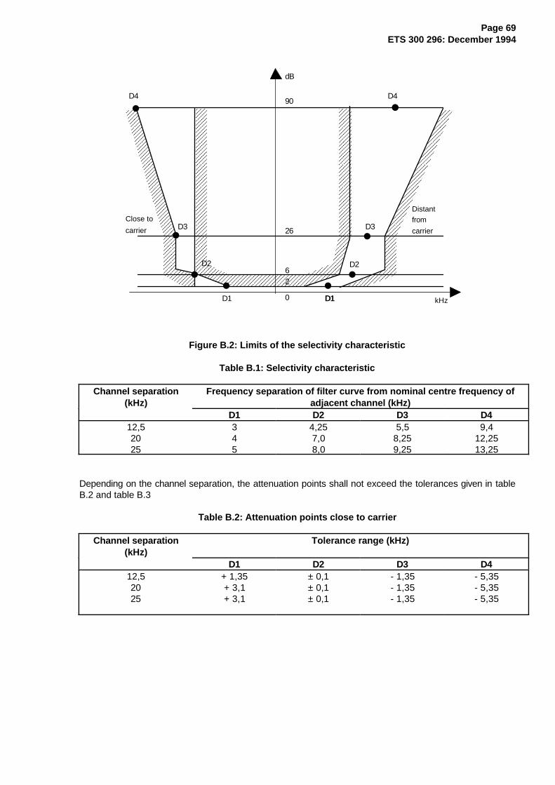
Page 69ETS 300 296: December 1994
AAAAAAAAAAAAAAAAAAAAAAAAAAAAAAAAAAAAAAAAAAAAAAAAAAAAAAAAAAAAAAAAAAAAAAAAAAAAAAAAAAAAAAAAAAAAAAAAAAAA
AAAAAAAAAAAAAAAAAAAAAAAAAAAAAAAAAAAAAAAAAAAAAAAAAAAAAAAAAAAAAAAAAAAAAAAAAAAAAAAAAAAAAAAAAAAAAAAAAAAA
AAAAAAAAAAAAAAAAAAAAAAAAAAAAAAAAAAAAAAAAAAAAAAAAAAAAAAAAAAAAAAAAAAAAAAAAAAAAAAAAAAAAAAAAAAAAAAAAAAAA
AAAAAAAAAAAAAAAAAAAAAAAAAAAAAAAAAAAAAAAAAAAAAAAAAAAAAAAAAAAAAAAAAAAAAAAAAAAAAAAAAAAAAAAAAAAAAAAAAAAA
AAAAAAAAAAAAAAAAAAAAAAAAAAAAAAAAAAAAAAAAAAAAAAAAAAAAAAAAAAAAAAAAAAAAAAAAAAAAAAAAAAAAAAAAAAAAAAAAAAAA
AAAAAAAAAAAAAAAAAAAAAAAAAAAAAAAAAAAAAAAAAAAAAAAAAA
AAAAAAAAAAAAAAAAAAAAAAAAAAAAAAAAAAAAAAAAAAAAAAAAAAAAAAAAAAAAAAAAAAAAAAAAAAAAAAAAAAAAAAAAAAAAAAAAAAAA
AAAAAAAAAAAAAAAAAAAAAAAAAAAAAAAAAAAAAAAAAAAAAAAAAAAAAAAAAAAAAAAAAAAAAAAAAAAAAAAAAAAAAAAAAAAAAAAAAAAA
AAAAAAAAAAAAAAAAAAAAAAAAAAAAAAAAAAAAAAAAAAAAAAAAAAAAAAAAAAAAAAAAAAAAAAAAAAA
AAAAAAAAAAAAAAAAAAAAAAAAAAAAAAAAAAAAAAAAAAAAAAAAAAAAAAAAAAAAAAAAAAAAAAAAAAAAAAAAAAAAAAAAAAAAAAAAAAAA
AAAAAAAAAAAAAAAAAAAAAAAAAAAAAAAAAAAAAAAAAAAAAAAAAAAAAAAAAAAAAAAAAAAAAAAAAAAAAAAAAAAAAAAAAAAAAAAAAAAA
AAAAAAAAAAAAAAAAAAAAAAAAAAAAAAAAAAAAAAAAAAAAAAAAAAAAAAAAAAAAAAAAAAAAAAAAAAAAAAAAAAAAAAAAAAAAAAAAAAAA
AAAAAAAAAAAAAAAAAAAAAAAAAAAAAAAAAAAAAAAAAAAAAAAAAAAAAAAAAAAAAAAAAAAAAAAAAAA
D4
D3
D2
D1D1 D1
D2
D3
dB
90
26
62
0
D4
Close to
carrier
Distantfrom
carrier
kHz
Figure B.2: Limits of the selectivity characteristic
Table B.1: Selectivity characteristic
Channel separation(kHz)
Frequency separation of filter curve from nominal centre frequency ofadjacent channel (kHz)
D1 D2 D3 D412,52025
345
4,257,08,0
5,58,259,25
9,412,2513,25
Depending on the channel separation, the attenuation points shall not exceed the tolerances given in tableB.2 and table B.3
Table B.2: Attenuation points close to carrier
Channel separation(kHz)
Tolerance range (kHz)
D1 D2 D3 D412,52025
+ 1,35+ 3,1+ 3,1
± 0,1± 0,1± 0,1
- 1,35- 1,35- 1,35
- 5,35- 5,35- 5,35
Page 70ETS 300 296: December 1994
Table B.3: Attenuation points distant from the carrier
Channel separation(kHz)
Tolerance range (kHz)
D1 D2 D3 D4
12,5 ± 2,0 ± 2,0 ± 2,0+ 2,0- 6,0
20 ± 3,0 ± 3,0 ± 3,0+ 3,0- 7,0
25 ± 3,5 ± 3,5 ± 3,5+ 3,5- 7,5
The minimum attenuation of the filter outside the 90 dB attenuation points shall be equal to or greater than90 dB.
Table B.4: Frequency displacement
Channel separation(kHz)
Specified necessary bandwidth (kHz)
Displacement from the - 6 dB point (kHz)
12,52025
8,51416
8,251317
The tuning of the power measuring receiver shall be adjusted away from the carrier so that the - 6 dBresponse nearest to the transmitter carrier frequency is located at a displacement from the nominal carrierfrequency as given in table B.4.
B.1.3 Oscillator and amplifier
The measurement of the reference frequencies and the setting of the local oscillator frequency shall bewithin ± 50 Hz.
The mixer, oscillator and the amplifier shall be designed in such a way that the measurement of theadjacent channel power of an unmodulated test signal source, whose noise has a negligible influence onthe measurement result, yields a measured value of ≤ - 90 dB for channel separation of 20 and 25 kHz andof ≤ - 80 dB for a channel separation of 12,5 kHz referred to the level of the test signal source.
The linearity of the amplifier shall be such that an error in the reading of no more than 1,5 dB will beobtained over an input level variation of 100 dB.
B.1.4 Attenuation indicator
The attenuation indicator shall have a minimum range of 80 dB and a resolution of 1 dB.
B.1.5 Level indicators
Two level indicators are required to cover the rms and the peak transient measurement.
B.1.5.1 Rms level indicator
The rms level indicator shall accurately indicate non-sinusoidal signals within a ratio of 10:1 between peakvalue and rms value.
B.1.5.2 Peak level indicator
The peak level indicator shall accurately indicate and store the peak power level. For the transient powermeasurement the indicator bandwidth shall be greater than twice the channel separation.
A storage oscilloscope or a spectrum analyser may be used as a peak level indicator.
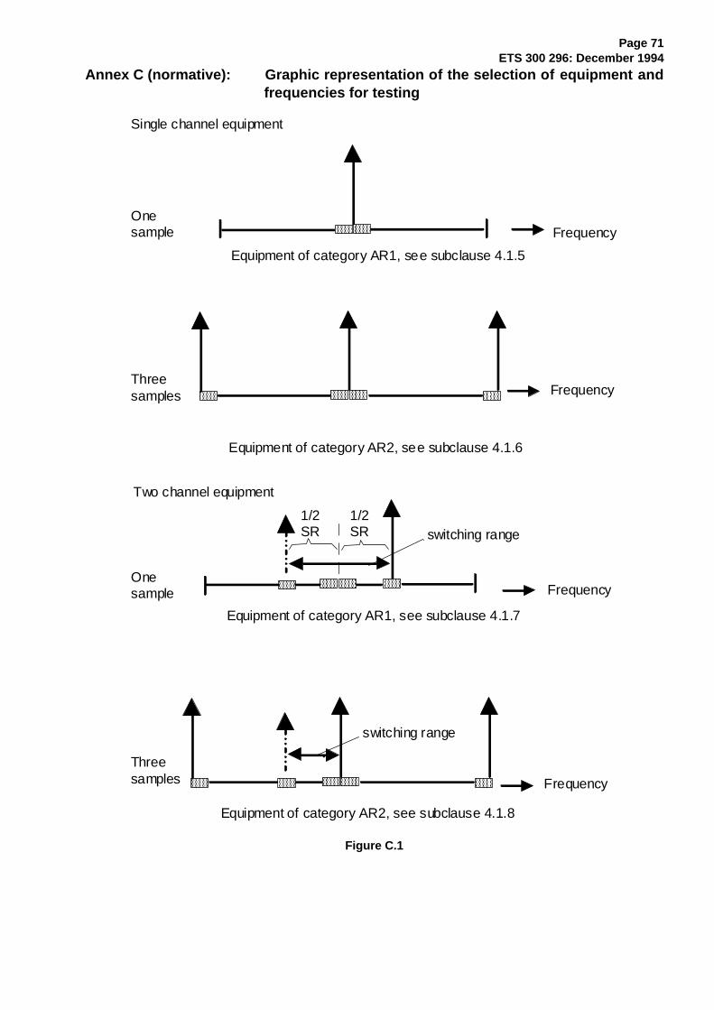
Page 71ETS 300 296: December 1994
Annex C (normative): Graphic representation of the selection of equipment andfrequencies for testing
AAAAAA
AAAAAA
AAAAAA
AAAAAA
AAAAAA
AAAAAA
AAAAAA
AAAAAA
AAAAAA
AAAAAA
AAAAAA
AAAAAA
AAAAAA
AAAAAA
AAAAAA
Single channel equipment
Onesample
Equipment of category AR1, see subclause 4.1.5
Frequency
FrequencyThreesamples
Equipment of category AR2, see subclause 4.1.6
Two channel equipment
Onesample Frequency
Equipment of category AR1, see subclause 4.1.7
switching range1/2SR
1/2SR
Frequency
Equipment of category AR2, see subclause 4.1.8
switching range
Threesamples
Figure C.1
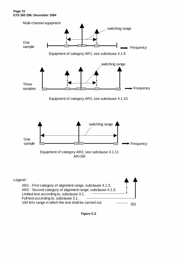
Page 72ETS 300 296: December 1994
AAAAAA
AAAAAA
AAAAAA
AAAAAA
AAAAAA
AAAAAA
AAAAAA
AAAAAA
AAAAAA
AAAAAA
AAAAAA
AAAAAA
AAAA
AAAAAA
AAAAAA
Onesample
Onesample
Threesamples
Frequency
Frequency
Frequency
switching range
switching range
switching range
Multi-channel equipment
Equipment of category AR1, see subclause 4.1.9
Equipment of category AR2, see subclause 4.1.10
Equipment of category AR2, see subclause 4.1.11AR=SR
Legend :
AR1 - First category of alignment range, subclause 4.1.3.AR2 - Second category of alignment range, subclause 4.1.3.Limited test according to, subclause 3.1.Full test according to, subclause 3.1.100 kHz range in which the test shall be carried out
Figure C.2
Page 73ETS 300 296: December 1994
Annex D (normative): Test discriminator
D.1 Characteristics of the test discriminator
The test discriminator consists of a mixer and local oscillator (auxiliary frequency) to convert the transmitterfrequency to be measured into the frequency of a broadband limiter amplifier and of a broadbanddiscriminator with the following characteristics:
- the discriminator shall be sensitive and accurate enough to cope with transmitter carrierpowers as low as 1 mW;
- the discriminator must be fast enough to display the frequency deviation (approx.100 kHz/100 µs);
- the discriminator output shall be dc coupled.

Page 74ETS 300 296: December 1994
History
Document history
December 1994 First Edition
December 1995 Converted into Adobe Acrobat Portable Document Format (PDF)
![WAC 296 - 46B CHAPTERlawfilesext.leg.wa.gov/law/WACArchive/2014/WAC 296... · (11/5/13) [ch. 296-46b wac p. 1] chapter 296-46b chapter 296-46b wac electrical safety standards, administration,](https://img.pdfslide.net/doc/110x75/5f937088d75d77697316c60c/wac-296-46b-296-11513-ch-296-46b-wac-p-1-chapter-296-46b-chapter.jpg)


![Chapter 296-19A Chapter 296-19A WAC VOCATIONAL …lawfilesext.leg.wa.gov/law/WACArchive/2012/WAC-296... · 296-19A-010 Vocational Rehabilitation [Ch. 296-19A WAC—p. 2] (11/15/11)](https://img.pdfslide.net/doc/110x75/6013de7783e2d5485a5626ed/chapter-296-19a-chapter-296-19a-wac-vocational-296-19a-010-vocational-rehabilitation.jpg)

![Chapter 296-841 Chapter 296-841 WAC AIRBORNE …lawfilesext.leg.wa.gov/law/WACArchive/2013/WAC-296-841-CHAPTE… · (2/20/07) [Ch. 296-841 WAC—p. 1] Chapter 296-841 Chapter 296-841](https://img.pdfslide.net/doc/110x75/605db1edd2831252ec0d5d41/chapter-296-841-chapter-296-841-wac-airborne-22007-ch-296-841-wacap-1.jpg)


![Chapter 296-52 WAC - leg.wa.govleg.wa.gov/CodeReviser/WACArchive/Documents/2018/WAC 296 - 52 CHAPTER.… · (8/1/17) [ch. 296-52 wac p. 1] chapter 296-52 chapter 296-52 wac safety](https://img.pdfslide.net/doc/110x75/5e1c55c238ed802015030b5e/chapter-296-52-wac-legwa-296-52-chapter-8117-ch-296-52-wac-p-1.jpg)