Embed Size (px)
Citation preview

EUROPEAN ETS 300 901
TELECOMMUNICATION December 1998
STANDARD Fifth Edition
Source: SMG Reference: RE/SMG-040340QR7
ICS: 33.020
Key words: Digital cellular telecommunications system, Global System for Mobile communications (GSM)
GLOBAL SYSTEM FOR MOBILE COMMUNICATIONS
R
Digital cellular telecommunications system (Phase 2+);Technical realization of the Short Message Service (SMS);
Point-to-Point (PP)(GSM 03.40 version 5.8.1 Release 1996)
ETSI
European Telecommunications Standards Institute
ETSI Secretariat
Postal address: F-06921 Sophia Antipolis CEDEX - FRANCEOffice address: 650 Route des Lucioles - Sophia Antipolis - Valbonne - FRANCEInternet: [email protected] - http://www.etsi.fr - http://www.etsi.org
Tel.: +33 4 92 94 42 00 - Fax: +33 4 93 65 47 16
Copyright Notification: No part may be reproduced except as authorized by written permission. The copyright and theforegoing restriction extend to reproduction in all media.
© European Telecommunications Standards Institute 1998. All rights reserved.

Page 2ETS 300 901 (GSM 03.40 version 5.8.1 Release 1996): December 1998
Whilst every care has been taken in the preparation and publication of this document, errors in content,typographical or otherwise, may occur. If you have comments concerning its accuracy, please write to"ETSI Standards Making Support Dept." at the address shown on the title page.

Page 3ETS 300 901 (GSM 03.40 version 5.8.1 Release 1996): December 1998
Contents
Foreword .......................................................................................................................................................7
Introduction....................................................................................................................................................7
1 Scope ..................................................................................................................................................9
2 Normative references..........................................................................................................................92.1 Definitions and abbreviations.............................................................................................11
2.1.1 Definitions......................................................................................................112.2.2 Abbreviations.................................................................................................13
3 Services and service elements .........................................................................................................133.1 Basic services....................................................................................................................133.2 Short Message Service elements ......................................................................................14
3.2.1 Validity-Period ...............................................................................................153.2.2 Service-Centre-Time-Stamp .........................................................................153.2.3 Protocol-Identifier ..........................................................................................153.2.4 More-Messages-to-Send...............................................................................153.2.5 Delivery of Priority and non-Priority Messages..............................................153.2.6 Messages-Waiting.........................................................................................153.2.7 Alert-SC.........................................................................................................173.2.8 Options concerning MNRF, MNRR, MCEF and MWD..................................183.2.9 Status report capabilities ...............................................................................193.2.10 Reply Path .....................................................................................................19
3.3 Unsuccessful short message TPDU transfer SC -> MS....................................................193.3.1 Errors occurring during transfer of TPDU to MS ...........................................193.3.2 Errors occurring after TPDU arrives at MS ...................................................19
3.4 Unsuccessful short message TPDU transfer MS -> SC....................................................213.4.1 Errors occurring during transfer of TPDU to SC............................................213.4.2 Errors occurring after TPDU arrives at SC....................................................21
3.5 Use of Supplementary Services in combination with the Short Message Service.............213.6 Applicability of Operator Determined Barring to the Short Message Service ....................213.7 Multiple short message transfer.........................................................................................213.8 SMS and Internet Electronic Mail interworking ..................................................................22
3.8.1 Basic Format .................................................................................................223.8.2 Optional Fields ..............................................................................................22
3.8.2.1 Subject.................................................................................233.8.2.2 Real Name...........................................................................233.8.2.3 Optional Control Flag...........................................................23
3.8.3 Text concatenation ........................................................................................233.8.4 Alternative characters for Internet email addresses in MO SMS. .................23
4 Network architecture .........................................................................................................................254.1 Basic network structure .....................................................................................................254.2 Transfer on link 3 ...............................................................................................................26
5 Service Centre and PLMN interconnection .......................................................................................265.1 Service centre connection..................................................................................................265.2 Routing requirements ........................................................................................................26
5.2.1 Mobile terminated short message .................................................................265.2.2 Mobile originated short message ..................................................................26
6 Service Centre functionality...............................................................................................................276.1 Service Centre capabilities ................................................................................................276.2 SC functional requirements ...............................................................................................27

Page 4ETS 300 901 (GSM 03.40 version 5.8.1 Release 1996): December 1998
7 MS functionality................................................................................................................................. 287.1 MS capabilities .................................................................................................................. 287.2 MS configuration ............................................................................................................... 28
8 MSC functionality .............................................................................................................................. 298.1 MSC functionality related to SM MT.................................................................................. 29
8.1.1 Functionality of the SMS-GMSC................................................................... 298.1.2 Functionality of the MSC............................................................................... 30
8.2 MSC functionality related to SM MO ................................................................................. 308.2.1 Functionality of the MSC............................................................................... 308.2.2 Functionality of the SMS-IWMSC ................................................................. 31
8.3 SMS-IWMSC functionality related to alerting .................................................................... 31
9 Protocols and protocol architecture .................................................................................................. 329.1 Protocol element features ................................................................................................. 32
9.1.1 Octet and Bit transmission order .................................................................. 329.1.2 Numeric and alphanumeric representation................................................... 32
9.1.2.1 Integer representation......................................................... 329.1.2.2 Octet representation ........................................................... 339.1.2.3 Semi-octet representation................................................... 339.1.2.4 Alphanumeric representation .............................................. 349.1.2.5 Address fields ..................................................................... 34
9.2 Service provided by the SM-TL ......................................................................................... 369.2.1 General ......................................................................................................... 369.2.2 PDU Type repertoire at SM-TL ..................................................................... 36
9.2.2.1 SMS-DELIVER type ............................................................ 379.2.2.1a SMS-DELIVER-REPORT type............................................ 389.2.2.2 SMS-SUBMIT type.............................................................. 409.2.2.2a SMS-SUBMIT-REPORT type.............................................. 419.2.2.3 SMS-STATUS-REPORT type............................................. 449.2.2.4 SMS-COMMAND type ........................................................ 46
9.2.3 Definition of the TPDU parameters............................................................... 479.2.3.1 TP-Message-Type-Indicator (TP-MTI) ................................ 479.2.3.2 TP-More-Messages-to-Send (TP-MMS)............................. 479.2.3.3 TP-Validity-Period-Format (TP-VPF) .................................. 489.2.3.4 TP-Status-Report-Indication (TP-SRI) ................................ 489.2.3.5 TP-Status-Report-Request (TP-SRR) ................................ 489.2.3.6 TP-Message-Reference (TP-MR)....................................... 489.2.3.7 TP-Originating-Address (TP-OA)........................................ 499.2.3.8 TP-Destination-Address (TP-DA)........................................ 499.2.3.9 TP-Protocol-Identifier (TP-PID)........................................... 499.2.3.10 TP-Data-Coding-Scheme (TP-DCS)................................... 519.2.3.11 TP-Service-Centre-Time-Stamp (TP-SCTS) ...................... 519.2.3.12 TP-Validity-Period (TP-VP) ................................................. 51
9.2.3.12.1 TP-VP (Relative format) ....................... 519.2.3.12.2 TP-VP (Absolute format ) ..................... 519.2.3.12.3 TP-VP ( Enhanced format ).................. 52
9.2.3.13 TP-Discharge-Time (TP-DT)............................................... 529.2.3.14 TP-Recipient-Address (TP-RA)........................................... 539.2.3.15 TP-Status (TP-ST) .............................................................. 539.2.3.16 TP-User-Data-Length (TP-UDL) ......................................... 549.2.3.17 TP-Reply-Path (TP-RP) ...................................................... 559.2.3.18 TP-Message-Number (TP-MN)........................................... 559.2.3.19 TP-Command-Type (TP-CT) .............................................. 559.2.3.20 TP-Command-Data-Length (TP-CDL) ................................ 559.2.3.21 TP-Command-Data (TP-CD) .............................................. 559.2.3.22 TP-Failure-Cause (TP-FCS) ............................................... 569.2.3.23 TP-User-Data-Header-Indicator (TP-UDHI)........................ 579.2.3.24 TP-User Data (TP-UD)........................................................ 57
9.2.3.24.1 Concatenated Short Messages............ 599.2.3.24.2 Special SMS Message Indication........ 619.2.3.24.3 Application Port Addressing 8 bit
address ................................................ 62

Page 5ETS 300 901 (GSM 03.40 version 5.8.1 Release 1996): December 1998
9.2.3.24.4 Application Port Addressing 16 bitaddress .................................................62
9.2.3.24.5 SMSC Control Parameters ..................639.2.3.24.6 UDH Source Indicator...........................64
9.2.3.25 TP-Reject-Duplicates (TP-RD) ............................................649.2.3.26 TP-Status-Report-Qualifier (TP-SRQ).................................649.2.3.27 TP-Parameter-Indicator (TP-PI) ........................................64
9.3 Service provided by the SM-RL .........................................................................................659.3.1 General..........................................................................................................659.3.2 Protocol element repertoire at SM-RL...........................................................65
9.3.2.1 RP-MO-DATA......................................................................669.3.2.2 RP-MT-DATA ......................................................................669.3.2.3 RP-ACK ...............................................................................669.3.2.4 RP-ERROR..........................................................................679.3.2.5 RP-ALERT-SC.....................................................................679.3.2.6 RP-SM-MEMORY-AVAILABLE ...........................................67
10 Fundamental procedures within the point-to-point SMS ...................................................................6810.1 Short message mobile terminated.....................................................................................6810.2 Short message mobile originated ......................................................................................7910.3 Alert transfer ......................................................................................................................84
11 Mapping of error causes between RP layers ....................................................................................8811.1 Mobile Terminated short message transfer .......................................................................8811.2 Memory available notification.............................................................................................8811.3 Mobile Originated short message transfer.........................................................................89
Annex A (informative): Protocol stacks for interconnecting SCs and MSCs...........................................90
Annex B (informative): Information now contained in GSM 03.38 ..........................................................91
Annex C (informative): Short message information flow.........................................................................92
Annex D (informative): Mobile Station reply procedures .......................................................................109
D.1 Introduction......................................................................................................................................109
D.2 The scope of applicability ................................................................................................................109
D.3 Terminology.....................................................................................................................................109
D.4 The reply path requesting procedure ..............................................................................................109
D.5 The reception of an original MT SM ................................................................................................110
D.6 The submission of the reply MO SM ...............................................................................................110
D.7 Usage of SCs for replying ...............................................................................................................110
D.8 Replying possibilities for Phase 1 mobile stations...........................................................................111
D.9 The resulting service for originating SMEs......................................................................................111
Annex E (informative): Change History.................................................................................................112
History........................................................................................................................................................113

Page 6ETS 300 901 (GSM 03.40 version 5.8.1 Release 1996): December 1998
Blank page

Page 7ETS 300 901 (GSM 03.40 version 5.8.1 Release 1996): December 1998
Foreword
This European Telecommunications Standard (ETS) has been produced by the Special Mobile Group(SMG) of the European Telecommunications Standards Institute (ETSI).
This ETS describes the point-to-point Short Message Service (SMS) of the digital cellulartelecommunications system.
The contents of this ETS is subject to continuing work within SMG and may change following formal SMGapproval. Should SMG modify the contents of this ETS, it will be resubmitted for OAP by ETSI with anidentifying change of release date and an increase in version number as follows:
Version 5.x.y
where:
5 indicates GSM Phase 2+ Release 1996
x the second digit is incremented for all other types of changes, i.e. technical enhancements,corrections, updates, etc.
y the third digit is incremented when editorial only changes have been incorporated in thespecification.
Transposition dates
Date of adoption of this ETS: 18 December 1998
Date of latest announcement of this ETS (doa): 31 March 1999
Date of latest publication of new National Standardor endorsement of this ETS (dop/e): 30 September 1999
Date of withdrawal of any conflicting National Standard (dow): 30 September 1999
Introduction
The Point-to-Point Short Message Service (SMS) provides a means of sending messages of limited sizeto and from GSM mobiles. The provision of SMS makes use of a Service Centre, which acts as a storeand forward centre for short messages. Thus a GSM PLMN needs to support the transfer of shortmessages between Service Centres and mobiles.
Two different point-to-point services have been defined: mobile originated and mobile terminated. Mobileoriginated messages will be transported from an MS to a Service Centre. These may be destined for othermobile users, or for subscribers on a fixed network. Mobile terminated messages will be transported froma Service Centre to an MS. These may be input to the Service Centre by other mobile users (via a mobileoriginated short message) or by a variety of other sources, e.g. speech, telex, or facsimile.

Page 8ETS 300 901 (GSM 03.40 version 5.8.1 Release 1996): December 1998
Blank page

Page 9ETS 300 901 (GSM 03.40 version 5.8.1 Release 1996): December 1998
1 Scope
This European Telecommunications Standard (ETS) describes the point-to-point Short Message Service(SMS) of the GSM PLMN system. It defines:
- the services and service elements;- the network architecture;- the Service Centre functionality;- the MSC functionality (with regard to the SMS);- the routing requirements;- the protocols and protocol layering;
for the Teleservices 21 and 22, as specified in the GSM 02.03 (ETS 300 905).
The use of radio resources for the transfer of short messages between the MS and the MSC is describedin GSM 04.11 (ETS 300 942) "Point-to-Point Short Message Service Support on Mobile Radio Interface",and is dealt with in that specification.
The network aspects of Short Message Service provision are outside the scope of this specification (i.e.the provision of network connectivity between the PLMN subsystems). There is no technical restrictionwithin this specification for the transfer of short messages between different PLMN's. Any such restrictionis likely to be subject to commercial arrangements and PLMN operators must make their own provision forinterworking or for preventing interworking with other PLMN’s as they see fit.
The required and assumed network service offered to the higher layers is defined in this specification.
The Cell Broadcast Short Message Service (Teleservice 23) is a separate service, and is described inGSM 03.41 (ETS 300 902) "Technical Realization of the Short Message Service - Cell Broadcast".
2 Normative references
This ETS incorporates by dated and undated references, provisions from other publications. Thesenormative references are cited at the appropriate places in the text and the publications are listedhereafter. For dated references, subsequent amendments to or revisions of any of these publicationsapply to this ETS only when incorporated in it by amendment or revision. For undated references, thelatest edition of the publication referred to applies.
[1] GSM 01.04 (ETR 350): "Digital cellular telecommunication system (Phase 2+);Abbreviations and acronyms".
[2] GSM 02.03 (ETS 300 905): "Digital cellular telecommunication system(Phase 2+); Teleservices supported by a GSM Public Land Mobile Network(PLMN)".
[3] GSM 02.04 (ETS 300 918): "Digital cellular telecommunication system(Phase 2+); General on supplementary services".
[4] GSM 02.41: "Digital cellular telecommunication system (Phase 2+); Operatordetermined barring".
[5] GSM 03.02: "Digital cellular telecommunication system (Phase 2+); Networkarchitecture".
[6] GSM 03.08: "Digital cellular telecommunication system (Phase 2+);Organization of subscriber data".
[7] GSM 03.11 (ETS 300 928): "Digital cellular telecommunication system(Phase 2+); Technical realization of supplementary services".
[8] GSM 03.15: "Digital cellular telecommunication system (Phase 2+); Technicalrealization of operator determined barring".

Page 10ETS 300 901 (GSM 03.40 version 5.8.1 Release 1996): December 1998
[9] GSM 03.38 (ETS 300 900): "Digital cellular telecommunication system(Phase 2+); Alphabets and language-specific information".
[10] GSM 03.41 (ETS 300 902): "Digital cellular telecommunication system(Phase 2+); Technical realization of Short Message Service Cell Broadcast(SMSCB)".
[11] GSM 03.47 (ETR 354): "Digital cellular telecommunication system (Phase 2+);Example protocol stacks for interconnecting Service Centre(s) (SC) andMobile-services Switching Centre(s) (MSC)".
[12] GSM 04.08 (ETS 300 557): "Digital cellular telecommunication system(Phase 2); Mobile radio interface layer 3 specification".
[13] GSM 04.11 (ETS 300 942): "Digital cellular telecommunication system(Phase 2+); Point-to-Point (PP) Short Message Service (SMS) support onmobile radio interface".
[14] GSM 07.05: "Digital cellular telecommunication system (Phase 2+); Use of DataTerminal Equipment - Data Circuit terminating Equipment (DTE - DCE) interfacefor Short Message Service (SMS) and Cell Broadcast Service (CBS)".
[15] GSM 09.02 (ETS 300 974): "Digital cellular telecommunication system(Phase 2+); Mobile Application Part (MAP) specification".
[16] GSM 11.11 (ETS 300 977): "Digital cellular telecommunication system(Phase 2+); Specification of the Subscriber Identity Module - Mobile Equipment(SIM - ME) interface".
[17] CCITT Recommendation E.164 (Blue Book): "Numbering plan for theISDN era".
[18] CCITT Recommendation E.163 (Blue Book): "Numbering plan for theinternational telephone service".
[19] CCITT Recommendation Q.771: "Specifications of Signalling System No.7;Functional description of transaction capabilities".
[20] CCITT Recommendation T.100 (Blue Book): "International informationexchange for interactive videotex".
[21] CCITT Recommendation T.101 (Blue Book): "International interworking forvideotex services".
[22] CCITT Recommendation X.121 (Blue Book): "International numbering plan forpublic data networks".
[23] CCITT Recommendation X.400 (Blue Book): "Message handling system andservice overview".
[24] ISO/IEC10646, "Universal Multiple-Octet Coded Character Set (USC); UCS2, 16bit coding".
[25] GSM 02.22: "Digital cellular telecommunication system (Phase 2+);Personalization of GSM Mobile Equipment (ME); Mobile functionalityspecification".
[26] GSM 03.42: "Digital cellular telecommunication system (Phase 2+);Compression Algorithm for Text Messaging Services”

Page 11ETS 300 901 (GSM 03.40 version 5.8.1 Release 1996): December 1998
2.1 Definitions and abbreviations
NOTE: Use of hyphens and full stops:
Care is needed when reading this specification as names containing words separatedby hyphens have different meaning than when separated with full stops. E.g.TS-Status-Report-Request is a parameter within a TS-Submit primitive, whilstTS-Status-Report. Request is a primitive in its own right.
2.1.1 Definitions
active MS: A switched-on mobile station with a SIM module attached.
alert-SC: Service element provided by a GSM PLMN to inform an SC which has previously initiatedunsuccessful short message delivery attempt(s) to a specific MS, that the MS is now recognized by thePLMN to have recovered operation.
status report: SC informing the originating MS of the outcome of a short message submitted to an SME.
Gateway MSC For Short Message Service (SMS-GMSC): A function of an MSC capable of receiving ashort message from an SC, interrogating an HLR for routing information and SMS info, and delivering theshort message to the VMSC of the recipient MS.
Interworking MSC For Short Message Service (SMS-IWMSC): A function of an MSC capable ofreceiving a short message from within the PLMN and submitting it to the recipient SC.
Messages-Waiting (MW): Service element that makes a PLMN store information(Messages-Waiting-Indication), listing those SCs that have made unsuccessful short message deliveryattempts to MSs in that PLMN.
Messages-Waiting-Indication (MWI): Data to be stored in the HLR and VLR with which an MS isassociated, indicating that there is one or more messages waiting in a set of SCs to be delivered to theMS (due to unsuccessful delivery attempt(s)).
Messages-Waiting-Data (MWD): A part of the MWI to be stored in the HLR. MWD consists of anaddress list of the SCs which have messages waiting to be delivered to the MS.
Mobile-Station-Memory-Capacity-Exceeded-Flag (MCEF): A part of the MWI to be stored in the HLR.MCEF is a Boolean parameter indicating if the address list of MWD contains one or more entries becausean attempt to deliver a short message to an MS has failed with a cause of MS Memory CapacityExceeded.
Mobile-Station-Not-Reachable-Flag (MNRF): The part of the MWI to be stored in the VLR and the HLR.MNRF is a Boolean parameter indicating if the address list of MWD contains one or more entries becausean attempt to deliver a short message to an MS has failed with a cause of Absent Subscriber.
Mobile-Station-Not-Reachable-Reason (MNRR): The part of the MWI in the HLR which stores thereason for an MS being absent when an attempt to deliver a short message to an MS fails at the MSC witha cause of Absent Subscriber.More-Messages-To-Send (MMS): Information element offering an MSreceiving a short message from an SC the information whether there are still more messages waiting tobe sent from that SC to the MS. The TP-MMS element (conveyed in the Transfer layer) is copied into theRP-MMS element (conveyed in the Relay layer). It is possible with Phase 2 and later versions of MAP(GSM TS 09.02) for the RP-MMS element to keep an SM transaction open between the GMSC and theMS in the case where there are more-messages-to-send. Earlier versions of MAP will support thetransport of the TP-MMS element.
priority: Service element enabling the SC or SME to request a short message delivery attempt to an MSirrespective of whether or not the MS has been identified as temporarily absent.
protocol-identifier: Information element by which the originator of a short message (either an SC or anMS) may refer to a higher layer protocol.

Page 12ETS 300 901 (GSM 03.40 version 5.8.1 Release 1996): December 1998
reply path procedure: A mechanism which allows an SME to request that an SC should be permitted tohandle a reply sent in response to a message previously sent from that SME to another SME. This mayhappen even though the SC may be unknown to the SME which received the initial message.
report: Response from either the network or the recipient upon a short message being sent from either anSC or an MS. A report may be a delivery report, which confirms the delivery of the short message to therecipient, or it may be a failure report, which informs the originator that the short message was neverdelivered and the reason why.
When issued by the Service Centre, the delivery report confirms the reception of the Short Messageby the SC, and not the delivery of the Short Message to the SME.
When issued by the Mobile Station, the delivery report confirms the reception of the Short Messageby the Mobile Station, and not the delivery of the Short Message to the user.
replace short message type: A range of values in the Protocol Identifier which allows an indication to besent with a short message (MT or MO) that the short message is of a particular type allowing the receivingMS or the SC to replace an existing message of the same type held in the SC, the ME or on the SIM,provided it comes:
- in MT cases: from the same SC and originating address;- in MO cases: from the same MS.
Service Centre (SC): Function responsible for the relaying and store-and-forwarding of a short messagebetween an SME and an MS. The SC is not a part of the GSM PLMN, however MSC and SC may beintegrated.
short message: Information that may be conveyed by means of the Short Message Service described inthis specification.
Short Message Entity (SME): An entity which may send or receive Short Messages. The SME may belocated in a fixed network, an MS, or an SC.
SMS-STATUS-REPORT: Short message transfer protocol data unit informing the receiving MS of thestatus of a mobile originated short message previously submitted by the MS, i.e. whether the SC was ableto forward the message or not, or whether the message was stored in the SC for later delivery.
SMS-COMMAND: Short message transfer protocol data unit which enables an MS to invoke an operationat the SC. An MS may then, for example, delete a short message, cancel a Status Report Request,enquire about the status of a short message or request another function to be performed by the SC.
The type of operation is indicated by the TP-Command-Type and the particular SM to operate on isindicated by the TP-Message-Number and the TP-Destination-Address. Receipt of an SMS-COMMAND isconfirmed by an RP-ACK or RP-ERROR. In the case of certain SMS-COMMANDs, anSMS-STATUS-REPORT may be sent, where the outcome of the SMS-COMMAND is passed in itsTP-Status field.
SMS-DELIVER: Short message transfer protocol data unit containing user data (the short message),being sent from an SC to an MS.
SMS-SUBMIT: Short message transfer protocol data unit containing user data (the short message), beingsent from an MS to an SC.
Service-Centre-Time-Stamp (SCTS): Information element offering the recipient of a short message theinformation of when the message arrived at the SM-TL entity of the SC. The time of arrival comprises theyear, month, day, hour, minute, second and time zone.
Validity-Period (VP): Information element enabling the originator MS to indicate the time period duringwhich the originator considers the short message to be valid.
Page 13ETS 300 901 (GSM 03.40 version 5.8.1 Release 1996): December 1998
2.2.2 Abbreviations
For the purposes of this ETS, the following abbreviations apply
E.163 CCITT Rec. E.163 (Blue Book)E.164 CCITT Rec. E.164 (Blue Book)
ACSE Association Control Service ElementSM MT Short Message Mobile Terminated Point-to-PointSM MO Short Message Mobile Originated Point-to-PointSM-AL Short Message Application LayerSM-TL Short Message Transfer LayerSM-RL Short Message Relay LayerSM-LL Short Message Lower LayersSM-TP Short Message Transfer Layer ProtocolSM-RP Short Message Relay Layer ProtocolSM-TS Short Message Transfer ServiceSM-RS Short Message Relay Service
T.100 CCITT Rec. T.100 (Blue Book)T.101 CCITT Rec. T.101 (Blue Book)TPDU Transfer protocol data unitX.121 CCITT Rec. X.121 (Blue Book)X.400 CCITT Rec. X.400 (Blue Book)
In addition to those above, definitions used in this ETS are listed in GSM 01.04.
3 Services and service elements
The SMS provides a means to transfer short messages between a GSM MS and an SME via an SC. TheSC serves as an interworking and relaying function of the message transfer between the MS and theSME.
This specification describes only the short message point-to-point services between the MS and SC. Itmay, however, refer to possible higher layer applications.
3.1 Basic services
The short message point-to-point services comprise two basic services:
SM MT (Short Message Mobile Terminated Point-to-Point);SM MO (Short Message Mobile Originated Point-to-Point).
SM MT denotes the capability of the GSM system to transfer a short message submitted from the SC toone MS, and to provide information about the delivery of the short message either by a delivery report or afailure report with a specific mechanism for later delivery; see figure 03.40/1.
SM MO denotes the capability of the GSM system to transfer a short message submitted by the MS to oneSME via an SC, and to provide information about the delivery of the short message either by a deliveryreport or a failure report. The message must include the address of that SME to which the SC shalleventually attempt to relay the short message; see figure 03.40/2.
The text messages to be transferred by means of the SM MT or SM MO contain up to 140 octets.

Page 14ETS 300 901 (GSM 03.40 version 5.8.1 Release 1996): December 1998
Short message delivery
>
<S C M S
Report
Figure 03.40/1: The Short Message Service mobile terminated, point-to-point
Short message submission
>
<S C M S
Report
Figure 03.40/2: The Short Message Service mobile originated, point-to-point
An active MS shall be able to receive a short message TPDU (SMS-DELIVER) at any time, independentlyof whether or not there is a speech or data call in progress. A report will always be returned to the SC;either confirming that the MS has received the short message, or informing the SC that it was impossibleto deliver the short message TPDU to the MS, including the reason why.
An active MS shall be able to submit a short message TPDU (SMS-SUBMIT) at any time, independentlyof whether or not there is a speech or data call in progress. A report will always be returned to the MS;either confirming that the SC has received the short message TPDU, or informing the MS that it wasimpossible to deliver the short message TPDU to the SC, including the reason why.
NOTE: When the transmission or reception of a short message coincide with a change ofstate in the MS, i.e. from busy to idle or from idle to busy, or during a handover, theshort message transfer might be aborted.
It is also possible for two short messages to be received in sequence having the sameoriginating address and identification, i.e. message reference number (MO) or SCTimestamp (MT). Such a situation may be due to errors at the RP or CP layers (e.g.during inter MSC handover) where it may be a duplicated message or otherwise it maybe a valid new message.
The receiving entity should therefore make provision to check other parameterscontained in the short message to decide whether the second short message is to bediscarded.
3.2 Short Message Service elements
The SMS comprises 7 elements particular to the submission and reception of messages:
Validity-Period;Service-Centre-Time-Stamp;Protocol-Identifier;More-Messages-to-Send;Priority;Messages-Waiting;Alert-SC.

Page 15ETS 300 901 (GSM 03.40 version 5.8.1 Release 1996): December 1998
3.2.1 Validity-Period
The Validity-Period is the information element which gives an MS submitting an SMS-SUBMIT to the SCthe possibility to include a specific time period value in the short message (TP-Validity-Period field, seeclause 9). The TP-Validity-Period parameter value indicates the time period for which the short messageis valid, i.e. for how long the SC shall guarantee its existence in the SC memory before delivery to therecipient has been carried out.
3.2.2 Service-Centre-Time-Stamp
The Service-Centre-Time-Stamp is the information element by which the SC informs the recipient MSabout the time of arrival of the short message at the SM-TL entity of the SC. The time value is included inevery SMS-DELIVER (TP-Service-Centre-Time-Stamp field, see clause 9) being delivered to the MS.
3.2.3 Protocol-Identifier
The Protocol-Identifier is the information element by which the SM-TL either refers to the higher layerprotocol being used, or indicates interworking with a certain type of telematic device.
The Protocol-Identifier information element makes use of a particular field in the message typesSMS-SUBMIT, SMS-DELIVER and SMS-COMMAND TP-Protocol-Identifier (TP-PID).
3.2.4 More-Messages-to-Send
The More-Messages-to-Send is the information element by which the SC informs the MS that there is oneor more messages waiting in that SC to be delivered to the MS. The More-Messages-to-Send informationelement makes use of a Boolean parameter in the message SMS-DELIVER, TP-More-Messages-to-Send(TP-MMS).
3.2.5 Delivery of Priority and non-Priority Messages
Priority is the information element provided by an SC or SME to indicate to the PLMN whether or not amessage is a priority message.
Delivery of a non-priority message will not be attempted if the MS has been identified as temporarilyabsent (see subclause 3.2.6).
Delivery of a non-priority message will be attempted if the MS has not been identified as temporarilyabsent irrespective of whether the MS has been identified as having no free memory capacity (seesubclause 3.2.6).
Delivery of a priority message will be attempted irrespective of whether or not the MS has been identifiedas temporarily absent, or having no free memory capacity.
3.2.6 Messages-Waiting
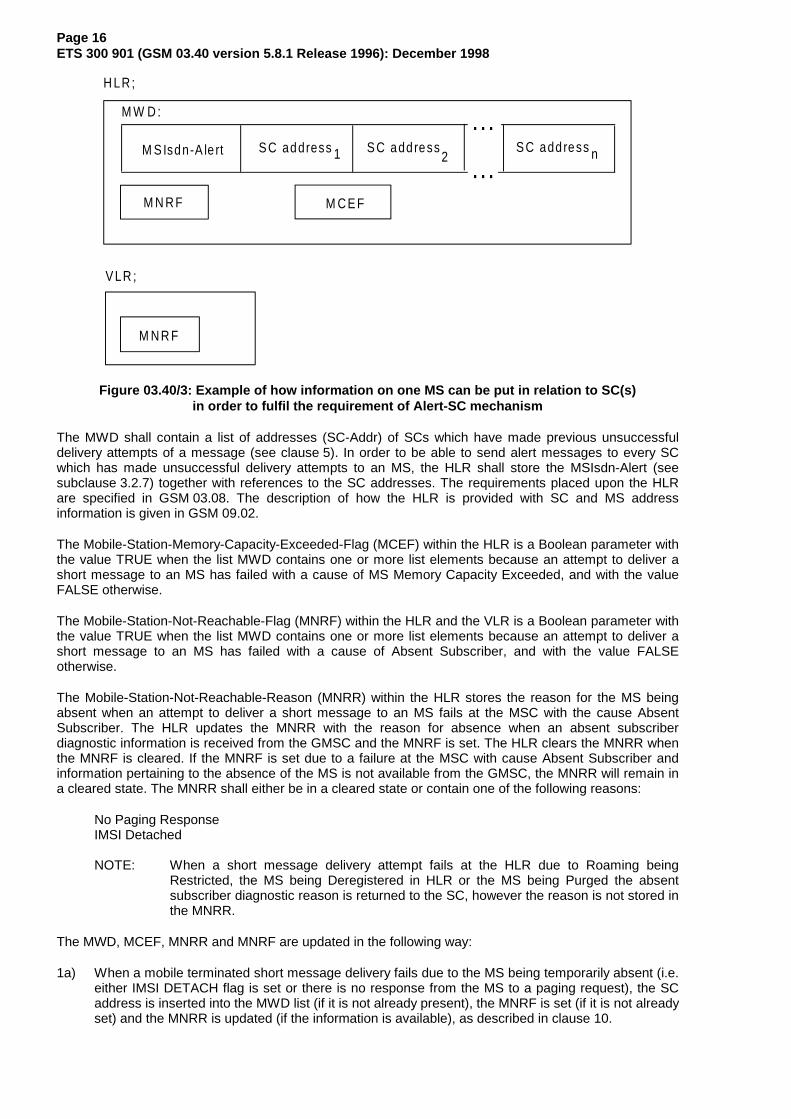
The Messages-Waiting is the service element that enables the PLMN to provide the HLR and VLR withwhich the recipient MS is associated with the information that there is a message in the originating SCwaiting to be delivered to the MS. The service element is only used in case of previous unsuccessfuldelivery attempt(s) due to temporarily absent mobile or MS memory capacity exceeded. This information,denoted the Messages-Waiting-Indication (MWI), consists of Messages-Waiting-Data (MWD), theMobile-Station-Not-Reachable-Flag (MNRF), the Mobile-Not-Reachable-Reason (MNRR) and theMobile-Station-Memory-Capacity-Exceeded-Flag (MCEF) located in the HLR, and theMobile-Station-Not-Reachable-Flag (MNRF) located in the VLR. figure 03.40/3 shows an example.
Page 16ETS 300 901 (GSM 03.40 version 5.8.1 Release 1996): December 1998
M S Isdn-A le rt S C address 1 S C address2
S C address n
M N R F M C E F
H LR ;
M W D :
M N R F
V LR ;
...
...
Figure 03.40/3: Example of how information on one MS can be put in relation to SC(s)in order to fulfil the requirement of Alert-SC mechanism
The MWD shall contain a list of addresses (SC-Addr) of SCs which have made previous unsuccessfuldelivery attempts of a message (see clause 5). In order to be able to send alert messages to every SCwhich has made unsuccessful delivery attempts to an MS, the HLR shall store the MSIsdn-Alert (seesubclause 3.2.7) together with references to the SC addresses. The requirements placed upon the HLRare specified in GSM 03.08. The description of how the HLR is provided with SC and MS addressinformation is given in GSM 09.02.
The Mobile-Station-Memory-Capacity-Exceeded-Flag (MCEF) within the HLR is a Boolean parameter withthe value TRUE when the list MWD contains one or more list elements because an attempt to deliver ashort message to an MS has failed with a cause of MS Memory Capacity Exceeded, and with the valueFALSE otherwise.
The Mobile-Station-Not-Reachable-Flag (MNRF) within the HLR and the VLR is a Boolean parameter withthe value TRUE when the list MWD contains one or more list elements because an attempt to deliver ashort message to an MS has failed with a cause of Absent Subscriber, and with the value FALSEotherwise.
The Mobile-Station-Not-Reachable-Reason (MNRR) within the HLR stores the reason for the MS beingabsent when an attempt to deliver a short message to an MS fails at the MSC with the cause AbsentSubscriber. The HLR updates the MNRR with the reason for absence when an absent subscriberdiagnostic information is received from the GMSC and the MNRF is set. The HLR clears the MNRR whenthe MNRF is cleared. If the MNRF is set due to a failure at the MSC with cause Absent Subscriber andinformation pertaining to the absence of the MS is not available from the GMSC, the MNRR will remain ina cleared state. The MNRR shall either be in a cleared state or contain one of the following reasons:
No Paging ResponseIMSI Detached
NOTE: When a short message delivery attempt fails at the HLR due to Roaming beingRestricted, the MS being Deregistered in HLR or the MS being Purged the absentsubscriber diagnostic reason is returned to the SC, however the reason is not stored inthe MNRR.
The MWD, MCEF, MNRR and MNRF are updated in the following way:
1a) When a mobile terminated short message delivery fails due to the MS being temporarily absent (i.e.either IMSI DETACH flag is set or there is no response from the MS to a paging request), the SCaddress is inserted into the MWD list (if it is not already present), the MNRF is set (if it is not alreadyset) and the MNRR is updated (if the information is available), as described in clause 10.

Page 17ETS 300 901 (GSM 03.40 version 5.8.1 Release 1996): December 1998
1b) When a mobile terminated short message delivery fails due to the MS memory capacity beingexceeded, the SC address is inserted into the MWD list (if it is not already present) and the MCEFis set (if it is not already set), as described in clause 10.
1c) If the MSIsdn used by the SC to address the recipient MS for alerting purposes is different from theMSIsdn-Alert of the MS (see subclause 3.2.7), the HLR returns the MSIsdn-Alert to the SC withinthe failure report, see "1c Failure report" in figures 03.40/15 and /16.
2a) When either the HLR or VLR detects that the MS (with a non-empty MWD and the MCEF clear inthe HLR and the MNRF set in the VLR) has recovered operation (e.g. has responded to a pagingrequest), the HLR directly or on request of the VLR will invoke operations to alert the SCs within theMWD (see subclause 3.2.7 and clause 10). Once the Alert SC operations have been invoked, theMNRF and MNRR are cleared. After each SC is alerted by the HLR, the address for that SC isdeleted from the MWD. If the MCEF is set in the HLR, the HLR clears the MNRF and MNRR, butdoes not invoke operations to alert the SCs within the MWD and data are not cleared from theMWD.
2b) When the HLR receives (via the MSC and the VLR) a notification that the MS (with a non-emptyMWD and the MCEF set in the HLR) has memory capacity available to receive one or more shortmessages, the HLR will invoke operations to alert the SCs within the MWD (see subclause 3.2.7and clause 10). Once the Alert SC operations have been invoked, the MNRF is cleared in the VLRand the MCEF, MNRF and MNRR are cleared in the HLR. After each SC is alerted by the HLR, theaddress for that SC is deleted from the MWD.
2c) When the HLR receives from the SMS-GMSC a notification that a short message has beensuccessfully delivered from an SC to an MS for which the MCEF is set and the MWD are not empty,the HLR will invoke operations to alert other SCs within the MWD (see subclause 3.2.7 andclause 10). Once the Alert SC operations have been invoked, the MCEF, MNRF and MNRR arecleared in the HLR. After each SC is alerted by the HLR, the address for that SC is deleted from theMWD. The SC which successfully delivered the message is also deleted from the MWD, if present.
2d) When the HLR receives (via the MSC and the VLR) a notification that the MS has memory capacityavailable to receive one or more short messages but the MCEF is not set and the MWD are empty,the HLR acknowledges the notification but does not alert any service centre.
3.2.7 Alert-SC
The Alert-SC is the service element, which may be provided by some GSM PLMNs, to inform the SC thatan MS
1) to which a delivery attempt has failed because the MS is not reachable or because the MS memorycapacity was exceeded;
and
2) which is now recognized by the PLMN:
a) to have resumed operation (e.g. to have responded to a paging request); or
b) to have memory newly available (which implies that the mobile is reachable).
is again ready to receive one or more short messages. The SC may - on reception of an Alert-SC - initiatethe delivery attempt procedure for the queued messages destined for this MS.
To each MS there may be allocated several MSIsdns. When the HLR is to alert an SC that an MS is againattainable it will use a specific MSIsdn value for this purpose; in this specification called MSIsdn-Alert.
NOTE: Repeated delivery attempts from the SC may be of two types:
i) A repeated delivery attempt because the SC has been informed that the MS isactive and available to receive short messages.
ii) An autonomous repeated delivery attempt by the SC.

Page 18ETS 300 901 (GSM 03.40 version 5.8.1 Release 1996): December 1998
The application of these two options is defined by the providers of the SC and thenetwork.
3.2.8 Options concerning MNRF, MNRR, MCEF and MWD
Setting the Mobile-Station-Not-Reachable-Flag (MNRF) in the VLR is mandatory. It is also mandatory forthe VLR to send the "MS Present" message (see clause 10) to the HLR when the MS has been detectedas becoming active and then to clear MWF.
The Messages-Waiting-Data (MWD, the Mobile-Station-Not-Reachable-Flag (MNRF), the Mobile-Station-Not-Reachable-Reason (MNRR) and the Mobile-Station-Memory-Capacity-Exceeded-Flag (MCEF)) withinthe HLR are optional, but if one is implemented all must be implemented. This is linked to thetransmission of the "Alert SC" message.
The following describes what happens when a delivery fails.
Case 1: MWD, MNRF, MNRR and MCEF are implemented in the HLR
In the case of a delivery failure (to an MS) with cause Absent Subscriber, the MSC requests theHLR to add, if needed, a new entry in the MWD with cause Absent Subscriber. This new entrycontains the SC address. The HLR sets its copy of the MNRF and updates the MNRR (if theinformation is available). The SC is notified of the failure, the reason for the MS being absent andalso of the MWD setting in the HLR within the Report message (see clause 10).
In the case of a delivery failure (to an MS) with cause Mobile Station Memory Capacity Exceeded,the MSC requests the HLR to add, if needed, a new entry in the MWD with cause Mobile StationMemory Capacity Exceeded. This new entry contains the SC address. The HLR sets the MCEF.The SC is notified of the failure and also of the MWD setting in the HLR within the Report message(see clause 10).
If the HLR indicates that it is able to store the SC address, then the SC will receive an Alert SCmessage when the MS becomes active.
If the HLR indicates that it is unable to store the SC address (e.g. because MWD is full), then theonly way to ensure delivery is for the SC to try to retransmit the message periodically.
When the HLR receives the MS Present message, if the MCEF is clear it sends an Alert SCmessage to the concerned SC and updates MWD.
When the HLR receives the MS Memory Capacity Available message, it sends an Alert SCmessage to the concerned SC, updates MWD and clears the MCEF.
Case 2: MWD, MNRF, MNRR and MCEF are not implemented in the HLR
In the case of a delivery failure, the SC is notified that the HLR is unable to store its address in theMWD. In case of a delivery failure (to a MS) with cause Absent Subscriber, the SC is notified of thereason for the MS being absent (if the information is available). The SC must retransmit the shortmessage periodically in order to ensure delivery.
The HLR discards the MS Present message received from the VLR without any failure or errorreport.
The HLR discards the MS Memory Capacity Available message received from the MS via the MSCand the VLR without any failure or error report.

Page 19ETS 300 901 (GSM 03.40 version 5.8.1 Release 1996): December 1998
3.2.9 Status report capabilities
The SMS also offers to the SC the capabilities of informing the MS of the status of a previously sentmobile originated short message. The status of the message can be:
- Successfully delivered to the SME;
- The SC was not able to forward the message to the SME. The reason can be an error of permanentor temporary nature. Permanent errors can be e.g. validity period expired, invalid SME address.Errors of temporary nature can be e.g. SC-SME connection being down, SME temporarilyunavailable.
This is achieved by the SC returning a status report TPDU (SMS-STATUS-REPORT) to the originatingMS when the SC has concluded the status of the short message. The status report may be initiated by astatus report request within the mobile originated short message. The status report TPDU is treated as anSMS-DELIVER TPDU by the SC when it comes to delivery procedures e.g. the alerting mechanism.
The SC may also return to a non-MS SME the status of a mobile terminated short message. This ishowever outside the scope of this specification.
The status report capabilities of the SMS are optional, i.e. the choice of whether to offer status report ornot is left to the SC operator.
3.2.10 Reply Path
Reply Path specified in this specification provides a way of both requesting and indicating a servicecentre's commitment to deliver a reply from the replying MS to the originating SME.
Annex D deals with MS procedures, which in general are outside the scope of GSM specifications.However, for advanced use of the SMS, including both application level protocols and human responses,it is of vital importance to guarantee that a reply-supporting MS is able to reply on every SM, to every SMEcapable of receiving such reply short messages.
3.3 Unsuccessful short message TPDU transfer SC -> MS
Unsuccessful message transfer SC -> MS may be caused by a variety of different errors. The descriptionof the occurrence of the different errors and how to handle and transfer the error indications is given inGSM 04.08, GSM 04.11 and GSM 09.02.
The different error indications which the SMS-GMSC shall be capable of returning to the SC following anunsuccessful short message TPDU transfer SC -> MS, are given in table 03.40/1. In some cases,additional diagnostic information may be provided.
3.3.1 Errors occurring during transfer of TPDU to MS
These errors are generally due to barring or unsupported service in the PLMN or MS. An error indication isreturned to the SC from the SMS-GMSC, but further diagnostic information from the MS will not beavailable.
3.3.2 Errors occurring after TPDU arrives at MS
These errors may occur due to the MS not supporting optional short message service features, or inconnection with a short message application. An error indication shall be returned to the SC from theSMS-GMSC. Additionally, a TPDU (SMS-DELIVER-REPORT) containing diagnostic information may beconveyed from the MS to the originating SC, transparently through the PLMN, by means defined inGSM 04.11 and GSM 09.02. The sending of the diagnostic information is optional at the MS, but when it issent, the PLMN shall convey the information to the SC, and the SC shall support reception of theinformation.

Page 20ETS 300 901 (GSM 03.40 version 5.8.1 Release 1996): December 1998
Table 03.40/1: Error indications related to mobile terminated short message transfer which may betransferred to the originating SC.
Error indication S 1) MeaningUnknown subscriber P The PLMN rejects the short message TPDU because there is not allocated
an IMSI or a directory number for the mobile subscriber in the HLR (seeGSM 09.02).
Teleservice not provisioned P The PLMN rejects the short message TPDU because the recipient MS hasno SMS subscription (see GSM 09.02).
Call barred T The PLMN rejects the short message TPDU due to barring of the MS (seeGSM 09.02, description of the Barring supplementary service, GSM 02.04and 03.11), and description of Operator Determined Barring, GSM 02.41and 03.15).
Facility not supported T The VPLMN rejects the short message TPDU due to no provision of theSMS in the VPLMN (see GSM 09.02).
Absent subscriber T The PLMN rejects the short message TPDU because- there was no paging response, (see GSM 04.08 & GMS 09.02)- the IMSI record is marked detached (see GSM 09.02),- the MS is subject to roaming restrictions (see "Roaming not allowed",GSM 09.02).- deregistered in the HLR. The HLR does not have an MSC number storedfor the target MS, (see GSM 09.02)- MS purged, (see GMS 09.02)
(The reasons for absence are assigned interger values in table 03.40/1a.The appropriate integer value is sent with the absent subscriber errorindication as defined in GSM 09.02)
MS busy for MT SMS T The PLMN rejects the short message TPDU because of congestionencountered at the visited MSC. Possible reasons include any of thefollowing events in progress:- short message delivery from another SC- IMSI detach- Location Update- paging- emergency call- call setup
SMS lower layerscapabilities not provisioned
T The PLMN rejects the short message TPDU due to MS not being able tosupport the Short Message Service.The short message transfer attempt is rejected either due to informationcontained in the class-mark, or the MSC not being able to establishconnection at SAPI = 3 (see GSM 04.08 and GSM 09.02).
Error in MS T The PLMN rejects the short message TPDU due to an error occurring withinthe MS at reception of a short message, e.g. lack of free memory capacity orprotocol error.
Illegal Subscriber P The PLMN rejects the short message TPDU because the MS failedauthentication
Illegal Equipment P The PLMN rejects the short message TPDU because the IMEI of the MSwas black-listed in the EIR
System failure T The PLMN rejects the short message TPDU due to network or protocolfailure others than those listed above (see GSM 09.02)
Memory Capacity Exceeded T The MS rejects the short message since it has no memory capacityavailable to store the message
1) : Status (Permanent or Temporary)
The relation between the two sets of error indications is given in the table 03.40/1. Each error is classifiedas either "Temporary" or "Permanent". This classification gives an indication of whether or not it isprobable that the MS becomes attainable within a reasonable period, and so provides the recommendedaction to be taken by the SC, i.e. either to store the message for later transfer, or to discard it.

Page 21ETS 300 901 (GSM 03.40 version 5.8.1 Release 1996): December 1998
Table 03.30/1a Assignment of integer values to reasons for absence (integer values must be inthe range of 0 to 255, see GSM 09.02)
Integer value Reason for absence0 - no paging response1 - IMSI detached2 - roaming restriction3 - deregistered in the HLR4 - MS purgedAll other integer values are reserved.
3.4 Unsuccessful short message TPDU transfer MS -> SC
The error indications related to mobile originated short message transfer which may be transferred to theoriginating MS are given in GSM 04.11. In some cases, additional diagnostic information may be provided.
3.4.1 Errors occurring during transfer of TPDU to SC
These errors are generally due to barring or unsupported service in the PLMN. An error indication isreturned to the MS from the MSC, but further diagnostic information from the SC will not be available.
3.4.2 Errors occurring after TPDU arrives at SC
These errors may occur due to the SC not supporting optional short message service features, or inconnection with a short message application. An error indication shall be returned to the MS from theMSC. Additionally, a TPDU (SMS-SUBMIT-REPORT) containing diagnostic information may be conveyedfrom the SC to the originating MS, transparently through the PLMN, as defined in GSM 09.02 andGSM 04.11. The sending of the diagnostic information is optional at the SC, but when it is sent, the PLMNshall convey the information to the MS, and the MS shall support reception of the information.
NOTE: The SMS-SUBMIT-REPORT is part of the negative acknowledgement to the mobileoriginated short message, and is not part of the status report capabilities described insubclause 3.2.9.
3.5 Use of Supplementary Services in combination with the Short Message Service
Only a sub-set of the Supplementary Services defined in GSM 02.04 and 03.11 may be used incombination with the Short Message Service. This sub-set comprises the following SupplementaryServices:
All the 5 Barring services
3.6 Applicability of Operator Determined Barring to the Short Message Service
The network feature Operator Determined Barring (see GSM 02.41) applies to the Short MessageService.
If a short message fails due to operator determined barring then an appropriate error cause is returned tothe originator.
3.7 Multiple short message transfer
To avoid the need for a mobile to be paged, authenticated etc. for each message waiting in the ServiceCentre, the SC may indicate to the GMSC that there are more messages to send. When this indication isgiven, MAP procedures are invoked such that this indication is passed to the VMSC, and the VMSC doesnot release the MS until all short messages waiting in the SC have been transferred.

Page 22ETS 300 901 (GSM 03.40 version 5.8.1 Release 1996): December 1998
3.8 SMS and Internet Electronic Mail interworking
The interworking between Internet electronic mail and SMS is offered in both directions which enablesnew and old mobiles to send/receive Internet electronic mails via SMS. The interworking is according tothe following procedures:
- An SMS message which is required to interwork with Internet email may have its TP-PID value setfor Internet electronic mail;
- Either single or concatenated SMS can be used to transport the email;
- Concatenation may be achieved by the TPUDH mechanism or text-based means described below;
- Email cc fields are not supported;
- Where multiple fields are present, additional spaces may be inserted by the sender to improvepresentation of the message. Spaces may not be inserted into the actual email address(e.g. [email protected]).
3.8.1 Basic Format
The basic format for transferring email in either direction consists of the following:
MT SMS:[<from-address><space>]<message>
MO SMS:[<to-address><space>]<message>
where [] denote optional fields and <> delimit fields.
The to-address or from address may take the form
User Name <[email protected]>
In the latter case the angle brackets <> are part of the address and are actually transmitted.
Depending on the nature of the gateway, the destination/origination address is either derived from thecontent of the SMS TP-OA or TP-DA field, or the TP-OA/TP-DA field contains a generic gateway addressand the to/from address is added at the beginning as shown above.
Multiple addresses may be identified in MO messages by separating each address by a comma like this:
address1,address2,address3<space><message>
It is optional for the receiving gateway to support this. If the receiving gateway does not support multiplemessages then it shall reject the original message by returning an appropriate error in a text message.
3.8.2 Optional Fields
The following further optional fields are supported. An email <-> SMS gateway may insert additionalspaces in the MT message for presentation to the user, and must accept additional spaces in the MOmessage from the user.

Page 23ETS 300 901 (GSM 03.40 version 5.8.1 Release 1996): December 1998
3.8.2.1 Subject
The subject is placed between the address and the message, delimited by round brackets () or precededby ##, for example:
[<to-address>](<subject>)<message>or
[<to-address>]##<subject>#<message>
An MO message may contain either format. An MT message may contain either format. Developersmust ensure that both forms are supported for full compatibility.
3.8.2.2 Real Name
The Real Name field contains the real name of the sender and is used only in MO messages. The SC oremail gateway will generate an email message according to standard email procedures containing RealName <[email protected]> (the angle brackets being part of the address and hence transmitted).If a subject is to be included with the Real Name then only the ## prefix is used.
The syntax is:
[<to-address>]#<real-name>[##<subject>]#<message>
3.8.2.3 Optional Control Flag
An optional control flag may be added to the start of the message in MO messages only. This consists ofa single character <CF> following a # symbol as follows:
[#<CF>#][<to-address>]<space><message>
This may also be used in combination with the above fields. It is intended for use where a particular SC oremail gateway specific function is required to be invoked. For example, the control flag #A# might add aparticular (pre-stored) signature to the end of the message or #R# might change the from-address to apre-stored value or #5# might add the text "Please phone me at the office". All of these functions areopen for definition by Service Centre or email gateway operators.
3.8.3 Text concatenation
If the GSM binary concatentation protocol is not supported by the transmitting or receiving entity, thefollowing textual concatenation mechanism may be used. The first message is ended with a + sign, andeach subsequent message start and end with + signs until the final message which starts with a + sign butdoes not end with a + sign.
<message1>++<message2>++<message3>
Any header fields placed on the front of an MO or MT message are not added to the second andsubsequent messages.
This provides a simple mechanism which is completely backward compatible. There is no indication ofthe number of messages and should a message be lost by the system or arrive out of sequence then theoriginal message cannot be reconstructed. Therefore, wherever possible the GSM binary concatenationmechanism specified in subclause 9.2.3.24.1 should be used instead.
3.8.4 Alternative characters for Internet email addresses in MO SMS.
It is difficult or impossible to generate some characters on a mobile phone and so the followingalternatives may be used:
@ may be replaced by *_ (underscore) may be replaced by $

Page 24ETS 300 901 (GSM 03.40 version 5.8.1 Release 1996): December 1998
3.9 SMS COMPRESSION
Short Messages may be compressed in accordance with the compression algorithm described in GSM03.42.
Compression and Decompression may take place between SME’s or between an SME and the SC.
The compression only applies to the TP-User-Data part of the TPDU and excludes any TP-User-Data-Header which may be present. The Compression Header ( see GSM TS 03.42 ) ust commence at the firstoctet of the TP-User-Data field immediately following any TP-User-Data-Header field which may bepresent.
The TP-UDL value must be set in accordance with that value defined for the compressed TP-User-Datacase in 9.2.3.16.
The TP-DCS parameter indicates whether or not a short message is compressed. If the TP-DCSparameter indicates that the short message is compressed then the alphabet encoding values ( bits 2 and3 in GSM 03.38 ) must be ignored by the receiving entity.
In the case where a short message after compression is greater than 140 octets (including theCompression Header and Footer ( see GSM TS 03.42 ) and any TP-User-Data-Header which may bepresent ) then the sending entity must concatenate the short message in the normal way as described in9.2.3.24.1 if it wishes to continue to send the short message. Only the first segment of the concatenatedshort message must contain the Compression Header defined in GSM TS 03.42. All segments other thanthe final segment must be 140 octets in length. Only the final segment contains the Compression Footer (see GSM 03.42 ).
For mobile terminated compressed messages, where the MMI or the Message Class indicated in the TP-DCS requires the message to be stored in the MS then the MS shall store the compressed message asreceived. In the case where the MS is capable of decompression then the MS may display thedecompressed message. Such an MS may optionally store the message in decompressed form subjectto the MS being configured to do this via MMI. However, prior to storing the message in decompressedform, the MS may have to create a concatenated SM and carry out component modification on the TP-UDL and TP-DCS values to indicate the correct length values and that the message is no longercompressed. Transfer of messages direct from the radio interface or those stored in the MS to a TE isaccording to the procedure defined in GSM TS 07.05 and is independent of whether the message iscompressed or uncompressed.
For mobile originated compressed messages, an MS capable of compression may compress a shortmessage generated within the MS itself prior to sending it to the radio interface. An MS capable ofcompression may optionally compress an uncompressed message received from a TE subject to the MSbeing configured to do this via MMI. In such a case the MS would have to carry out componentmodification on the TP-UDL and TP-DCS values to indicate the correct length values and that themessage is compressed. A TE may send a message ( compressed or uncompressed ) to the MS usingthe procedures defined in GSM TS 07.05. . The MS will store the compressed message as receivedand/or transfer it directly to the radio interface.

Page 25ETS 300 901 (GSM 03.40 version 5.8.1 Release 1996): December 1998
4 Network architecture
4.1 Basic network structure
The exchange of messages between an MS and an SME involves the entities shown in figure 03.40/4.
The basic network structure of the SMS is depicted in figure 03.40/5.
..S M E S C M S C M S
S M S -G M S C /S M S -IW M S C
*
O uts ide the scope o f the G S Mspec ifica tions
Ins ide the scope o f the G S Mspec ifica tions
> <
*) : SMS-GMSC when the short message is transferred from the SC to the MS, SMS-IWMSC whenthe short message is transferred from the MS to the SC. The SC may be integrated with theSMS-GMSC/SMS-IWMSC.
Figure 03.40/4: Entities involved in the provision of SM MT and SM MO: SC,SMS-GMSC/SMS-IWMSC, MSC and MS
The links of figure 03.40/5 support the short message transfer in the following way:
- message transfer on link 1 is described in clause 5;
- the operations performed on links 2 and 4 is described in GSM 09.02;
- message transfer on link 3 is described in subclause 4.2;
- message transfer on link 5 is supported by protocol described in GSM 04.11.
S C M S C M SS M S -G M S C /S M S -IW M S C
H LR V LR
↑ ↑
< >> >< <1. 3 . 5 .
2 . 4 .
< <
Figure 03.40/5: The main network structure serving as a basis for the short message transfer

Page 26ETS 300 901 (GSM 03.40 version 5.8.1 Release 1996): December 1998
4.2 Transfer on link 3
The link 3 is used to support communications between MSCs (MSC, SMS-GMSC, SMS-IWMSC). Twocases can be distinguished according to whether or not the MSCs are located in the same PLMN.
In the first case, the link definition is left to the operators. For example, this link may use:
- PSPDN or- CCITT SS no 7 (according to GSM 09.02).
In the second case, CCITT SS no 7 shall be used over link 3 according to GSM 09.02, unless otherwisebilaterally agreed.
5 Service Centre and PLMN interconnection
This specification deals with the SC only with regard to the interchange of messages between SC and MS.Only the requirements put upon the SC by the SMS functionality are specified in this specification.
5.1 Service centre connection
One SC may be connected to several PLMNs, and may be connected to several MSCs (SMS-GMSCs orSMS-IWMSCs) within one and the same PLMN.
The SC is addressed from the mobile by an E.164 number in the numbering plan of the PLMN to whichthe SC is connected. This E.164 number shall uniquely identify the SC to that PLMN.
There may be an intermediate network between the PLMN and the SC; in this case the PLMN mustautonomously make a connection to the SC using the SC address in this intermediate network.
No mandatory protocol between the SC and the MSC below the transfer layer is specified by GSM; this isa matter for agreement between SC and PLMN operators. However, annex A provides an exampleprotocol stack which could be used.
5.2 Routing requirements
5.2.1 Mobile terminated short message
The SC sends the short message to the SMS-GMSC. The SMS-GMSC interrogates the HLR to retrieverouting information necessary to forward the short message, and then sends the message to the relevantMSC, transiting other networks if necessary. The MSC then sends the short message to the MS.
5.2.2 Mobile originated short message
The MS sends the short message to the MSC. The MS will always address the required SC by an E.164address. The visited PLMN will route the message to the appropriate SMS-IWMSC in the SC's PLMN,transiting other networks if necessary.

Page 27ETS 300 901 (GSM 03.40 version 5.8.1 Release 1996): December 1998
6 Service Centre functionality
In this specification, only the SC functionality related to the short message point-to-point service betweenthe SC and the MS is specified.
6.1 Service Centre capabilities
The SC should be capable of
- submitting a short message to an MS, retaining the responsibility of the message until
1) the report has been received; or
2) the Validity-Period expires.
- receiving a report from the PLMN;
- receiving a short message from an MS;
- returning a report to the PLMN for a previously received short message.
6.2 SC functional requirements
The detailed functionality of the SC is outside the scope of this specification, and is for the SC operator todefine. However, the following functional requirements are mandatory for all SCs in order to support theSM-TP (see clause 9) towards the PLMN:
1) To identify each SMS-DELIVER sent to an MS in a unique way, a time stamp value is included inthe field TP-Service-Centre-Time-Stamp, TP-SCTS, of the SMS-DELIVER. The time stamp givesthe time when the message arrived at the SC with the accuracy of a second. If two or moremessages to the same MS arrive at the SC within one second, the SC shall modify the time stampof those messages in such a way that
a) all messages to the MS contain different time stamps;b) the modification of the time stamps is kept to a minimum.
2) The SC is only allowed to have one outstanding SMS-DELIVER (i.e. a message for which a reporthas not been received) to a specific MS at a given time.
3) The SC shall be able to initiate overwriting of short messages previously received by the SC ifrequested by the same originating address (MS or any other source) by use of the same messagetype.

Page 28ETS 300 901 (GSM 03.40 version 5.8.1 Release 1996): December 1998
7 MS functionality
In this specification, only the MS functionality related to the short message point-to-point service betweenthe SC and the MS is specified.
7.1 MS capabilities
The MS, when equipped for SMS, should be capable of
- submitting a short message TPDU to an SC, retaining the responsibility of the message until:
1) the report arrives from the network; or
2) a timer expires.
- receiving a short message TPDU from an SC;
- returning a delivery report to the network for a previously received short message;
- receiving a report from the network;
- notifying the network when it has memory capacity available to receive one or more short messageswhen it has previously rejected a short message because its memory capacity was exceeded;
- notifying the SC when a short message is intended to replace a short message the MS haspreviously submitted to the same destination address.
It is recommended that an MS supporting both replying and automatic SC selection (as specified inclause D.2 of annex D) follows procedures specified in annex D when replying to MT short messages withMO short messages.
It is recommended that an MS supporting a capability for requesting a reply path follows proceduresspecified in annex D.
7.2 MS configuration
The reference configuration is assumed as in figure 03.40/6, i.e. only the case where the terminal isintegrated in the MS is considered.
M TOUm
Figure 03.40/6: Reference configuration of the MS which apply to the SMS
NOTE: It is foreseen that a terminal interface may be offered, e.g. for higher layer protocols,memory capacity reasons or to be able to type in mobile originated messages. Thisterminal interface is regarded as an implementation option, although, where offered, itmust be based upon an R- or S-reference point. GSM 07.05 provides an examplebased on the R reference point.

Page 29ETS 300 901 (GSM 03.40 version 5.8.1 Release 1996): December 1998
8 MSC functionality
The overall requirements to the MSC with respect to handling of the Short Message Service point-to-pointis to cater for the routing and necessary intermediate buffering of the short messages.
8.1 MSC functionality related to SM MT
8.1.1 Functionality of the SMS-GMSC
When receiving a short message TPDU from the SC, the SMS-GMSC is responsible for the followingoperations:
- reception of the short message TPDU;- inspection of the parameters.
NOTE: The SMS-GMSC may be identical to the MSC.
if parameters are incorrect:
- returning the appropriate error information to the SC in a failure report (see clauses 9 and 10);
if errors are not found within parameters:
- interrogating the HLR ("sendRoutingInfoForShortMsg", see clause 10); retrieving routing informationor possible error information;
if HLR is returning error information:
- returning the appropriate error information to the SC in a failure report (see clauses 9 and 10);
if no errors are indicated by the HLR:
- transferring the short message TPDU to the MSC using the routing information obtained from theHLR ("forwardShortMessage", see clause 10).
When receiving the report associated with the short message from the MSC (positive or negative outcomeof "forwardShortMessage", see clause 10), the SMS-GMSC is responsible for the following operations:
if the report indicates successful delivery:
- notifying the HLR of the successful delivery, which will cause the HLR to alert any service centreswhose addresses are stored in the MWD for the MS;
if the report is a failure report indicating "absent subscriber" (see subclause 3.3):
- requesting the HLR to insert the address of the originating SC into the MWD (if implemented) withcause Absent Subscriber ("setMessageWaitingData", see clauses 9 and 10);
- informing the HLR of the reason for the MS being absent (if this information is available)- establishing, where necessary, a link with the addressed SC (see clause 5);- creating and sending the report to the SC which should include the reason for the MS being absent
(if this information is available) so that the SC may adjust any retry algorithm appropriately (seeclauses 9 and 10);
if the report is a failure report indicating "MS memory capacity exceeded" (see subclause 3.3):
- requesting the HLR to insert the address of the originating SC into the MWD (if implemented) withcause MS Memory Capacity Exceeded ("setMessageWaitingData", see clauses 9 and 10);
- establishing, where necessary, a link with the addressed SC (see clause 5);
- creating and sending the report to the SC (see clauses 9 and 10).

Page 30ETS 300 901 (GSM 03.40 version 5.8.1 Release 1996): December 1998
8.1.2 Functionality of the MSC
When receiving a short message TPDU from the SMS-GMSC ("forwardShortMessage", see clause 10),the MSC is responsible for the following operations:
- reception of the short message TPDU;
- retrieving information from the VLR ("sendInfoFor-MT-SMS", see clause 10); location area addressand, when appropriate, error information;
if errors are indicated by the VLR:
- returning the appropriate error information to the SMS-GMSC in a failure report (negative outcomeof "forwardShortMessage" see clauses 10 and 11);
if no errors are indicated by the VLR:
- transferring the short message to the MS (see GSM 04.11).
When receiving a confirmation that the message is received by the MS (see GSM 04.11):
- relaying the delivery confirmation to the SMS-GMSC in a delivery report (positive outcome of"forwardShortMessage", see clauses 10 and 11).
When receiving a failure report of the short message transfer to the MS (see GSM 04.11):
- returning the appropriate error information to the SMS-GMSC in a failure report (negative outcomeof "forwardShortMessage", see clause 10).
When receiving a notification from the MS that it has memory available to receive one or more shortmessages (see GSM 04.11):
- relaying the notification to the VLR ("mSMemoryCapacityAvailable", see clause 10);
if errors are indicated by the VLR:
- returning the appropriate error information to the MS in a failure report (negative outcome of"ReadyForSM", see clauses 10 and 11).
When there is an ongoing MT-SMS transfer to the MS (see GSM 04.11), or other busy condition for MT-SMS, the MSC has the option to store the TPDU in a queue for a short time (which must be shorter thanthe supervision timer defined in GSM 09.02). The maximum time that a message may be queued isrelated to the permitted delay for the MSC to respond to the SMS-GMSC. When the MS becomesavailable for MT-SMS transfer, the stored TPDUs are delivered to the MS on a first-in first-out basis. If amessage is not successfully transferred to the MS within the permitted time, the MSC returns anappropriate error to the SMS-GMSC.
8.2 MSC functionality related to SM MO
8.2.1 Functionality of the MSC
When receiving a short message TPDU from the MS, the MSC is responsible for the following operations:
- reception of the short message TPDU (see GSM 04.11);
- retrieving information from the VLR ("sendInfoForMO-SMS", see clause 10); the MSISDN of the MSand, when appropriate, error information. The retrieval of information from the VLR is followed bythe VLR investigating the MWF (to be used in the alerting procedure, see clause 10)
if errors are indicated by the VLR:

Page 31ETS 300 901 (GSM 03.40 version 5.8.1 Release 1996): December 1998
- returning the appropriate error information to the MS in a failure report (negative outcome of"sendInfoForMO-SMS" see clauses 10 and 11);
if no errors are indicated by the VLR:
- inspection of the TPDU parameters;
if parameters are incorrect:
- returning the appropriate error information to the MS in a failure report (see GSM 04.11);
if no parameter errors are found:
- examination of the destination address;
NOTE: The SMS-IWMSC may be identical to the MSC.
- transferring the short message TPDU to the SMS-IWMSC ("forwardShortMessage", see clause 10).
When receiving the report of the short message from the SMS-IWMSC (positive or negative outcome ofthe "forwardShortMessage", see clause 10), the MSC is responsible for the following operations:
- relaying the report to the MS (see GSM 04.11).
8.2.2 Functionality of the SMS-IWMSC
When receiving a short message TPDU from the MSC ("forwardShortMessage", see clause 10), theSMS-IWMSC is responsible for the following operations:
- reception of the short message TPDU;- establishing, where necessary, a link with the addressed SC (see clause 5);- transferring the short message TPDU to the SC (if the address is valid).
If a report associated with the short message is received from the SC, the SMS-IWMSC is responsible forthe following operations:
- relaying of the report to the MSC (positive or negative outcome of "forwardShortMessage", seeclause 10).
If a report associated with the short message is not received from the SC before a timer expires or if theSC address is invalid, the SMS-IWMSC is responsible for the following operations:
- returning the appropriate error information to the MSC in a failure report (negative outcome of"forwardShortMessage", see clause 10).
The value of the timer is dependent on the protocol between the SC and the SMS-IWMSC.
8.3 SMS-IWMSC functionality related to alerting
When receiving an alert from the HLR ("alertServiceCentre", see clause 10), the SMS-IWMSC isresponsible for the following operations:
- inspect the SC address;- generate an RP-Alert-SC (see clause 9);- transferring the RP-Alert-SC to the SC.
NOTE: If the SC address is not valid, then no further action will be taken.

Page 32ETS 300 901 (GSM 03.40 version 5.8.1 Release 1996): December 1998
9 Protocols and protocol architecture
The protocol layers of the SMS are structured as shown in figure 03.40/7.
>
>
>
>
>
>
>
>
>
<
<
<
<
<
<
<
<
<
S M E S CS M S -G M S C /S M S -IW M S C M S C M S
S M -A L
S M -T L
S M -R L
S M -LL
Figure 03.40/7: Protocol layer overview for the Short Message Service point-to-point
This specification specifies the protocol at the SM-TL, the service offered by the SM-TL at the MS and theSC, and the service offered by the SM-RL at the SC.
9.1 Protocol element features
9.1.1 Octet and Bit transmission order
The octets are transmitted according to their individual numbering; the octet with the lowest number beingtransmitted first. The bits within each octet are transmitted according to their individual numbering also;the bits with the lowest internal number being transmitted first.
9.1.2 Numeric and alphanumeric representation
For parameters within the TPDUs, there are four ways of numeric representation: Integer representation,octet, semi-octet and alphanumeric representation.
9.1.2.1 Integer representation
Wherever the bits from a number of octets, complete or in fractions, are to represent an integer, theinterpretation will be according to the following:
1) Between octets: The octets with the lowest octet numbers will contain the most significant bits.2) Within an octet: The bits with the highest bit numbers will be the most significant.
Below is given an example of octet and bit representation and transmission order of an integerrepresented field.
Let the 2 rightmost bits of octet no 5, the complete octet no 6 and 7, and the 3 leftmost bits of octet no 8represent an integer, as shown in figure 03.40/8.

Page 33ETS 300 901 (GSM 03.40 version 5.8.1 Release 1996): December 1998
.. . . . .O ct.no.7 6 5 4 3 2 1 0
..
.. . . . . ..
5
6
7
8
β)
α)
b1 b0
b7 b6 b5 b4 b3 b2 b1 b0
5 5
6 6 6 6 6 6 6 6
7 7 7 7 7 7 7 7b7 b6
b6
b5
b5
b4 b3 b2 b1 b08 b7 8 8
5b1
5b0
6b7
6b6 b1
6b0 7b7
7b6 b1 7b0 8 b7 8 b6 8 b5.... 6 .... 7
*)>
*)>
§)
5b0 5 b1 b2 5 b3 5b4 5b5 5b6 5b7 b0 6 b1 6b2 6b3 6b4 6 b5 6b6 6 b7 > 5 6
> 7b0 7b1
7b2 7b3 7b4 7b5 7b6 7b7 b0 8b1 8 b2 8 b3 8 b4 b5 8b6 8b78 8
*) : Bits not representing the integer.
Figure 03.40/8: 21 bits from the octets 5, 6, 7, and 8 in a short message α) will represent an integeras shown in β), and will be transmitted in an order as shown in Γ)
9.1.2.2 Octet representation
A field which is octet represented, will always consist of a number of complete octets. Each octet withinthe field represents one decimal digit. The octets with the lowest octet numbers will contain the mostsignificant decimal digits.
9.1.2.3 Semi-octet representation
A field which is semi-octet represented, will consist of a number of complete octets and - possibly - onehalf octet. Each half octet within the field represents one decimal digit. The octets with the lowest octetnumbers will contain the most significant decimal digits. Within one octet, the half octet containing the bitswith bit numbers 0 to 3, will represent the most significant digit.
In the case where a semi-octet represented field comprises an odd number of digits, the bits with bitnumbers 4 to 7 within the last octet are fill bits and shall always be set to "1111".
If a mobile receives an address field containing non-integer information in the semi-octets other than"1111" (e.g. 1110) it shall display the semi-octet as the representation given in GSM 04.08 under "calledBCD number", viz 1010="*", 1011="#", 1100="a", 1101="b", 1110="c". In the event of a discrepancybetween the values quoted here and the values specified in GSM 04.08 then GSM 04.08 shall takeprecedence. If a mobile receives "1111" in a position prior to the last semi-octet then processing shallcommence with the next semi-octet and the intervening semi-octet will be ignored.
Within each semi octet, the bits with the highest bit numbers will be the most significant.

Page 34ETS 300 901 (GSM 03.40 version 5.8.1 Release 1996): December 1998
Below is given an example:
Octet no:
D ig it 2 D ig it 1
D ig it 4 D ig it 3
D ig it 5
n+1
n+2
n+3 11 11
9.1.2.4 Alphanumeric representation
A field which uses alphanumeric representation will consist of a number of 7-bit characters represented asthe default alphabet defined in GSM 03.38.
9.1.2.5 Address fields
Address fields used by SM-RL are specified in GSM 04.11 and 09.02.
Each address field of the SM-TL consists of the following sub-fields: An Address-Length field of one octet,a Type-of-Address field of one octet, and one Address-Value field of variable length; as shown below:
A ddress-LengthT ype-of-A ddress
A ddress-V alueA ddr.
..
................................
1
2
3
4
5
µ
..The Address-Length field is an integer representation of the number of useful semi-octets within theAddress-Value field, i.e. excludes any semi octet containing only fill bits.

Page 35ETS 300 901 (GSM 03.40 version 5.8.1 Release 1996): December 1998
The Type-of-Address field format is as follows:
Type-of-num ber N um bering-p lan -iden tif ica tion1
Type-of-number:
Bits 6 5 4
0 0 0 Unknown 1)
0 0 1 International number 2)
0 1 0 National number 3)
0 1 1 Network specific number 4)
1 0 0 Subscriber number 5)
1 0 1 Alphanumeric, (coded according to GSM TS03.38 7-bit default alphabet)
1 1 0 Abbreviated number1 1 1 Reserved for extension
The MS will interpret reserved values as "Unknown" but will store them exactly as received.
The SC may reject messages with a type of number containing a reserved value or one which is notsupported.
1) "Unknown" is used when the user or network has no a priori information about the numbering plan.In this case, the Address-Value field is organized according to the network dialling plan, e.g. prefixor escape digits might be present.
2) The international format shall be accepted also when the message is destined to a recipient in thesame country as the MSC.
3) Prefix or escape digits shall not be included.4) "Network specific number" is used to indicate administration/service number specific to the serving
network, e.g. used to access an operator.5) "Subscriber number" is used when a specific short number representation is stored in one or more
SCs as part of a higher layer application. (Note that "Subscriber number" shall only be used inconnection with the proper PID referring to this application).
Numbering-plan-identification (applies for Type-of-number = 000,001,010)
Bits 3 2 1 0
0 0 0 0 Unknown0 0 0 1 ISDN/telephone numbering plan (E.164/E.163)0 0 1 1 Data numbering plan (X.121)0 1 0 0 Telex numbering plan1 0 0 0 National numbering plan1 0 0 1 Private numbering plan1 0 1 0 ERMES numbering plan (ETSI DE/PS 3 01-3)1 1 1 1 Reserved for extension
All other values are reserved.
For Type-of-number = 101 bits 3,2,1,0 are reserved and shall be transmitted as 0000. Note that foraddressing any of the entities SC, MSC or MS, Numbering-plan-identification = 0001 will always be used.However, for addressing the SME, any specified Numbering-plan-identification value may be used.
The MS will interpret reserved values as "Unknown" but will store them exactly as received.
The SC may reject messages with a type of number containing a reserved value or one which is notsupported.
Within the Address-Value field, either a semi-octet or an alphanumeric1) representation applies.

Page 36ETS 300 901 (GSM 03.40 version 5.8.1 Release 1996): December 1998
The maximum length of the full address field (Address-Length, Type-of-Address and Address-Value) is12 octets.
1) Applies only to addressing at the SM-TL.
9.2 Service provided by the SM-TL
9.2.1 General
The Short Message Transfer Layer (SM-TL) provides a service to the Short Message Application Layer(SM-AL). This service enables the SM-AL to transfer short messages to its peer entity, receive shortmessages from its peer entity and receive reports about earlier requests for short messages to betransferred.
In order to keep track of messages and reports about those messages, primitives between the SM-AL andSM-TL contain a Short Message Identifier (SMI), which is a reference number for the message associatedwith the primitive. This Short Message Identifier is mapped to and from the Short Message Identifier usedbetween the SM-TL and the Short Message Relay Layer (SM-RL). The Short Message Identifier is notcarried between entities and therefore a given message may have different SMIs at the MS and SC sides(see subclause 9.3.1 below).
The SM-TL communicates with its peer entity by the protocol described in the following sections.
9.2.2 PDU Type repertoire at SM-TL
The SM-TL comprises the following six PDUs:
SMS-DELIVER, conveying a short message from the SC to the MS;SMS-DELIVER-REPORT, conveying a failure cause (if necessary);SMS-SUBMIT, conveying a short message from the MS to the SC;SMS-SUBMIT-REPORT, conveying a failure cause (if necessary);SMS-STATUS-REPORT, conveying a status report from the SC to the MS;SMS-COMMAND, conveying a command from the MS to the SC.

Page 37ETS 300 901 (GSM 03.40 version 5.8.1 Release 1996): December 1998
9.2.2.1 SMS-DELIVER type
Basic elements of the SMS-DELIVER type:
Abbr. Reference P 1) R2) Description
TP-MTI TP-Message-Type-Indicator M 2b Parameter describing themessage type.
TP-MMS TP-More-Messages-to-Send M b Parameter indicating whether ornot there are more messages tosend
TP-RP TP-Reply-Path M b Parameter indicating that ReplyPath exists.
TP-UDHI TP-User-Data-Header-Indicator O b Parameter indicating that theTP-UD field contains a Header
TP-SRI TP-Status-Report-Indication O b Parameter indicating if the SMEhas requested a status report.
TP-OA TP-Originating-Address M 2-12o Address of the originating SME.
TP-PID TP-Protocol-Identifier M o Parameter identifying the abovelayer protocol, if any
TP-DCS TP-Data-Coding-Scheme M o Parameter identifying the codingscheme within the TP-User-Data.
TP-SCTS TP-Service-Centre-Time-Stamp M 7o Parameter identifying time whenthe SC received the message.
TP-UDL TP-User-Data-Length M I Parameter indicating the length ofthe TP-User-Data field to follow.
TP-UD TP-User-Data O 3)
1) Provision; Mandatory (M) or Optional (O).2) Representation; Integer (I), bit (b), 2 bits (2b), Octet (o), 7 octets (7o), 2-12 octets (2-12o)3) Dependent on the TP-DCS

Page 38ETS 300 901 (GSM 03.40 version 5.8.1 Release 1996): December 1998
Layout of SMS-DELIVER:
................................
. . . . . . . . . . . . .
B it no .
N um ber o focte ts
1
1
2
2 to 12
11
1
1
0 to 140
T P -M T I, TP -M M S ,T P -S R I, T P -U D H I, TP -R P
T P -O A
TP -P ID
T P -D C S
T P -S C TS
T P -U D L
T P -U D
7 6 5 4 3 2 1 0
NOTE: Any unused bits will be set to zero by the sending entity and will be ignored by thereceiving entity.
9.2.2.1a SMS-DELIVER-REPORT type
An SMS-DELIVER-REPORT TPDU is carried as a RP-User-Data element within an RP-ERROR PDU andis part of the negative acknowledgement to an SMS-DELIVER or SMS-STATUS-REPORT.
An SMS-DELIVER-REPORT TPDU is also carried as a RP-User-Data element within an RP-ACK PDUand is part of a positive acknowledgement to a SMS-DELIVER or SMS-STATUS REPORT
(i) SMS-DELIVER-REPORT for RP-ERROR
Basic elements of the SMS-DELIVER-REPORT type:
Abbr. Reference P 1) P2) Description
TP-MTI TP-Message-Type-Indicator M 2b Parameter describing the message type
TP-FCS TP-Failure-Cause M I Parameter indicating the reason forSMS-DELIVER failure
1) Provision: Mandatory (M) or Optional (O)2) Representation: Integer (I), bit (b), 2bits (2b), octet (o)

Page 39ETS 300 901 (GSM 03.40 version 5.8.1 Release 1996): December 1998
Layout of SMS-DELIVER-REPORT:
Number 1 TP-MTI
of octets 1 TP-FCS
Bits 7 - 2 in octet 1 are presently unused and the sender shall set them to zero. If any of these bits isnon-zero, the receiver shall not examine the other field and shall treat the TP-Failure-Cause as"Unspecified error cause".
(ii) SMS-DELIVER-REPORT for RP-ACK
Basic elements of the SMS-DELIVER-REPORT type:
Abbr Reference P 1) P2) Description
TP-MTI TP-Message Type Indicator M 2b Parameter describing the message type
TP-UDHI TP-User-Data-Header-Indication
O b Parameter indicating that the TP-UD fieldcontains a Header
TP-PI TP-Parameter-Indicator M o Parameter indicating the presence of any ofthe optional parameters which follow
TP-PID TP-Protocol-Identifier O o see subclause 9.2.3.9
TP-DCS TP-Data-Coding-Scheme O o see subclause 9.2.3.10
TP-UDL TP-User-Data-Length O o see subclause 9.2.3.16
TP-UD TP-User-Data O 3) 4) see subclause 9.2.3.24
1) Provision: Mandatory (M) or Optional (O)2) Representation: Integer (I), Bit (b), 2 bits (2b), octet (o)3) Dependent upon the TP-DCS4) The TP-User-Data field in the SMS-DELIVER-REPORT is only available for use by the MT.
Layout of SMS-DELIVER-REPORT:
Bit NumberNumber
ofOctets
6 5 4 3 2 1 0
1 TP-MTI, TP-UDH
1 TP-PI
0,1 TP-PID
0,1 TP-DCS
0,1 TP-UDL
0 to 159 TP-UD
Bits 7 - 2 in the TP-MTI are presently unused in the SMS-DELIVER-REPORT and the sender shall setthem to zero,. If any of these bits is non-zero, the receiver shall ignore them.

Page 40ETS 300 901 (GSM 03.40 version 5.8.1 Release 1996): December 1998
9.2.2.2 SMS-SUBMIT type
Basic elements of the SMS-SUBMIT type:
Abbr. Reference P 1) P2) Description
TP-MTI TP-Message-Type-Indicator M 2b Parameter describing the message type.
TP-RD TP-Reject-Duplicates M b Parameter indicating whether or not theSC shall accept an SMS-SUBMIT for anSM still held in the SC which has the samTP-MR and the same TP-DA as apreviously submitted SM from the sameOA
TP-VPF TP-Validity-Period-Format M 2b Parameter indicating whether or not theTP-VP field is present.
TP-RP TP-Reply-Path M b Parameter indicating the request for ReplyPath.
TP-UDHI TP-User-Data-Header-Indicator O b Parameter indicating that the TP-UD fieldcontains a Header.
TP-SRR TP-Status-Report-Request O b Parameter indicating if the MS isrequesting a status report.
TP-MR TP-Message-Reference M I Parameter identifying the SMS-SUBMIT.
TP-DA TP-Destination-Address M 2-12o Address of the destination SME.
TP-PID TP-Protocol-Identifier M o Parameter identifying the above layerprotocol, if any
TP-DCS TP-Data-Coding-Scheme M o Parameter identifying the coding schemewithin the TP-User-Data.
TP-VP TP-Validity-Period O o/7o Parameter identifying the time from wherethe message is no longer valid.
TP-UDL TP-User-Data-Length M I Parameter indicating the length of theTP-User-Data field to follow.
TP-UD TP-User-Data O 3)
1) Provision; Mandatory (M) or Optional (O).2) Representation; Integer (I), bit (b), 2 bits (2b), Octet (o), 7 octets (7o), 2-12 octets (2-12o).3) Dependent on the TP-DCS

Page 41ETS 300 901 (GSM 03.40 version 5.8.1 Release 1996): December 1998
Layout of SMS-SUBMIT:
................................
. . . . . . . . . . . . .
7 6 5 4 3 2 1 0B it no.
N um be r o focte ts
1
1
2 to 12
1
1
1
1
0 to 140
TP -P ID
T P -D C S
T P -U D L
T P-U D
1
2
TP -D A
T P -M T I, TP -R D , TP -V P F,T P -S R R , T P -U D H I, TP -R P
T P -M R
1
0, 1 o r 7 . . . . . . . . . . . . . TP -V P
NOTE: Any unused bits will be set to zero by the sending entity and will be ignored by thereceiving entity.
9.2.2.2a SMS-SUBMIT-REPORT type
An SMS-SUBMIT-REPORT TPDU is carried as a RP-User-Data element within an RP-ERROR PDU andis part of the negative acknowledgement to an SMS-SUBMIT or SMS-COMMAND.
An SMS-SUBMIT-REPORT TPDU is also carried as a RP-User-Data element with an RP-ACK PDU andis part of a positive acknowledgement to a SMS-SUBMIT or SMS-COMMAND.
(I) SMS-SUBMIT-REPORT for RP-ERROR
Basic elements of the SMS-SUBMIT-REPORT type:
Abbr. Reference P 1) P2) Description
TP-MTI TP-Message-Type-Indicator M 2b Parameter describing the message type
TP-FCS TP-Failure-Cause M I Parameter indicating the reason forSMS-SUBMIT failure
1) Provision: Mandatory (M) or Optional (O)2) Representation: Integer (I), bit (b), 2bits (2b), octet (o)

Page 42ETS 300 901 (GSM 03.40 version 5.8.1 Release 1996): December 1998
Layout of SMS-SUBMIT-REPORT:
Bit no. 7 6 5 4 3 2 1 0
Number 1 TP-MTI
of octets 1 TP-FCS
Bits 7 - 2 in octet 1 are presently unused and the sender shall set them to zero. If any of these bits isnon-zero, the receiver shall not examine the other field and shall treat the TP-Failure-Cause as"Unspecified error cause".
(ii) SMS-SUBMIT-REPORT for RP -ACK
Basic elements of the SMS-SUBMIT_REPORT type:
Abbr Reference P 1) P2) Description
TP-MTI TP-Message Type-Indicator M 2b Parameter describing the message type
TP-UDHI TP-User-Data-Header-Indication
O b Parameter indicating that the TP-UD fieldcontains a Header
TP-PI TP-Parameter-Indicator M o Parameter indicating the presence of any ofthe optional parameters which follow
TP-SCTS TP-Service-Centre-Time-Stamp
M 7o
5)
Parameter identifying the time when the SCreceived the SMS-SIBMIT
See sect 9.2.3.11
TP-PID TP-Protocol-Identifier O o See sect 9.2.3.9
TP-DCS TP-Data-Coding-Scheme O o see sect 9.2.3.10
TP-UDL TP-User-Data-Length O o see sect 9.2.3.16
TP-UD TP-User-Data O 3) 4) see sect 9.2.3.24
1) Provision: Mandatory (M) or Optional (O);
2) Representation: Integer (I), Bit (B), 2bits (2b), octet (o);
3) Dependent upon the TP-DCS;
4) The TP-User-Data field in the SMS-SUBMIT-REPORT is only available for use by the SC.;
5) This same time value will also be carried in the SMS-STATUS-REPORT relating to a particular SM.See subclause 9.2.2.3. This will allow the submitting SME to associate a particular SMS-SUBMITwith a subsequent SMS-STATUS-REPORT by correlating the TP-SCTS values.

Page 43ETS 300 901 (GSM 03.40 version 5.8.1 Release 1996): December 1998
Layout of SMS-SUBMIT REPORT
Bit Number
Numberof
Octets
7 6 5 4 3 2 1 0
1 TP-MTI, TP-UDHI
1 TP-PI
7 TP-SCTS
0,1 TP-PID
0,1 TP-DCS
0,1 TP-UDL
0 to 152 TP-UD
Bits 7 - 2 in the TP-MTI are presently unused in the SMS-SUBMIT-REPORT and the sender shall setthem to zero. If any of these bits is non-zero, the receiver shall ignore them.

Page 44ETS 300 901 (GSM 03.40 version 5.8.1 Release 1996): December 1998
9.2.2.3 SMS-STATUS-REPORT type
Basic elements of the SMS-STATUS-REPORT type:
Abbr. Reference P 1) R2) Description
TP-MTI TP-Message-Type-Indicator M 2b Parameter describing the message type
TP-UDHI TP-User-Data-Header-Indication O b Parameter indicating that the TP-UD fieldcontains a Header
TP-MMS TP-More-Messages-to-Send M b Parameter indicating whether or not thereare more messages to send
TP-SRQ TP-Status-Report-Qualifier M b Parameter indicating whether thepreviously submitted TPDU was anSMS_SUBMIT or an SMS-COMMAND
TP-MR TP-Message-Reference 3) M I Parameter identifying the previouslysubmitted SMS-SUBMIT orSMS-COMMAND
TP-RA TP-Recipient-Address M 2-12o Address of the recipient of the previouslysubmitted mobile originated shortmessage
TP-SCTS TP-Service-Centre-Time-Stamp M 7o Parameter identifying time when the SCreceived the previously sentSMS-SUBMIT
TP-DT TP-Discharge-Time M 7o Parameter identifying the time associatedwith a particular TP-ST outcome
TP-ST TP-Status M o Parameter identifying the status of thepreviously sent mobile originated shortmessage
TP-PI TP-Parameter-Indicator O
4)
o Parameter indicating the presence of anyof the optional parameters which follow
TP-PID TP-Protocol-Identifier O o see sect 9.2.3.9. TP-PID of original SMS-SUBMIT
TP-DCS TP-Data-Coding-Scheme O o see sect 9.2.3.10
TP-UDL TP-User-Data-Length O o see sect 9.2.3.16
TP-UD TP-User-Data O 5) see sect 9.2.3.24
1) Provision: Mandatory (M) or Optional (O).2) Representation: Integer (I), bit (b), 2 bits (2b), Octet (o), 7 octets (7o), 2-12 octets (2-12o)3) Where the SMS-STATUS-REPORT is the result of an SMS-COMMAND and the
TP-Command-Type was an Enquiry, the TP-MR returned in the SMS-STATUS-REPORT shall bethe TP-MN which was sent in the SMS-COMMAND (i.e. the TP-MR of the previously submitted SMto which the Enquiry refers).
4) Mandatory if any of the optional parameters following TP-PI is present, otherwise optional.5) TP-UD contains information related to a SMS-DELIVER; can contain information transported in the
TP-UD of SMS-DELIVER-REPORT, and information inserted by the SMSC. The length of the TP-UD field is limited and might not be long enough to fit information both from the original receivingterminal (as included into the SMS-DELIVER-REPORT) and information added by the SMSC. Inthese cases the former information has higher priority, and the latter will be truncated.

Page 45ETS 300 901 (GSM 03.40 version 5.8.1 Release 1996): December 1998
Layout of SMS-STATUS-REPORT:
B it no .
N um ber o f oc te ts TP -M TI, T P -M M S , TP -S R Q
TP -M R
TP -R A
TP -S C TS
TP -D T
T P -S T
1
7
7
2 to 12
2
1
1
1
7 6 5 4 3 2 1 0
................................
NOTE: Any unused bits will be set to zero by the sending entity and will be ignored by thereceiving entity.

Page 46ETS 300 901 (GSM 03.40 version 5.8.1 Release 1996): December 1998
9.2.2.4 SMS-COMMAND type
Basic elements of the SMS-COMMAND type:
Abbr. Reference P 1) R2) Description
TP-MTI TP-Message-Type-Indicator M 2b Parameter describing the type
TP-UDHI TP-User-Data-Header-Indication O b Parameter indicating that the TP-CD fieldcontains a Header
TP-SRR TP-Status-Report- Request O b Parameter indicating if the SMSCommand is requesting a status report.
TP-MR TP-Message Reference M I Parameter identifying theSMS-COMMAND
TP-PID TP-Protocol- Identifier M o Parameter identifying the above layerprotocol, if any
TP-CT TP-Command-Type M o Parameter specifying which operation isto be performed on a SM
TP-MN TP-Message-Number M3) o Parameter indicating which SM in the SCto operate on
TP-DA TP-Destination-Address M4) 2-12o Parameter indicating the DestinationAddress to which the TP-Commandrefers
TP-CDL TP-Command-Data-Length M o Parameter indicating the length of theTP-CD field in octets
TP-CD TP-Command-Data O o Parameter containing user data
1) Provision: Mandatory (M) or Optional (O).2) Representation: Integer (I), bit (b), 2bits (2b), octet (o)3) For TP-Command-Types which are not for a specific SM this field shall be ignored when received.
Its value is of no concern but the field must be present to maintain the structure.4) For certain TP-Command-Types which operate on a specific SM (e.g. Enquire, Delete etc.) the full
TP-DA must be specified. For TP-Command-Types which do not operate on a specific SM, theaddress length must be set to zero indicating that the Address-Value fields are not present. TheType-of-Address field must be present (see 9.1.2.5) and shall be set to zero and ignored.

Page 47ETS 300 901 (GSM 03.40 version 5.8.1 Release 1996): December 1998
Layout of SMS-COMMAND:
Bit no. 7 6 5 4 3 2 1 0Number 1 TP-MTI, TP-SRR,
TP-UDHIof octets 1 TP-MR
1 TP-PID
1 TP-CT
1 TP-MN
2 to 12 TP-DA
………….…………………….
1 TP-CDL
………….…………………….0 to 156 TP-CD
NOTE: The maximum guaranteed length of TP-CD is 146 octets. In order to achieve themaximum stated above (156 octets), the TP-DA field must have a length of 2 octets.
9.2.3 Definition of the TPDU parameters
9.2.3.1 TP-Message-Type-Indicator (TP -MTI)
The TP-Message-Type-Indicator is a 2-bit field, located within bits no 0 and 1 of the first octet ofall PDUs which can be given the following values:
bit1 bit0 Message type
0 0 SMS-DELIVER (in the direction SC to MS)0 0 SMS-DELIVER REPORT (in the direction MS to SC)1 0 SMS-STATUS-REPORT (in the direction SC to MS)1 0 SMS-COMMAND (in the direction MS to SC)0 1 SMS-SUBMIT (in the direction MS to SC)0 1 SMS-SUBMIT-REPORT (in the direction SC to MS)1 1 Reserved
If an MS receives a TPDU with a "Reserved" value in the TP-MTI it shall process the message as if it werean "SMS-DELIVER" but store the message exactly as received.
9.2.3.2 TP-More-Messages-to-Send (TP -MMS)
The TP-More-Messages-to-Send is a 1-bit field, located within bit no 2 of the first octet of SMS-DELIVERand SMS-STATUS-REPORT, and to be given the following values:
Bit no 2: 0 More messages are waiting for the MS in this SC1 No more messages are waiting for the MS in this SC
NOTE: In the case of SMS-STATUS-REPORT this parameter refers to messages waiting forthe mobile to which the status report is sent. The term message in this context refersto SMS-messages or status reports.

Page 48ETS 300 901 (GSM 03.40 version 5.8.1 Release 1996): December 1998
9.2.3.3 TP-Validity-Period-Format (TP-VPF)
The TP-Validity-Period-Format is a 2-bit field, located within bit no 3 and 4 of the first octet ofSMS-SUBMIT, and to be given the following values:
bit4 bit30 0 TP-VP field not present1 0 TP-VP field present - relative format0 1 TP-VP field present - enhanced format1 1 TP-VP field present - absoluteformat
Any unsupported value may be rejected by the SC by returning the ‘TP-VPF not supported’ TP-FCS valuein the SMS Submit Report for RP-Error.
9.2.3.4 TP-Status-Report-Indication (TP-SRI)
The TP-Status-Report-Indication is a 1-bit field, located within bit no. 5 of the first octet of SMS-DELIVER,and to be given the following values:
Bit no. 5: 0 A status report will not be returned to the SME1 A status report will be returned to the SME
9.2.3.5 TP-Status-Report-Request (TP-SRR)
The TP-Status-Report-Request is a 1-bit field, located within bit no. 5 of the first octet of SMS-SUBMITand SMS-COMMAND, and to be given the following values:
Bit no. 5: 0 A status report is not requested1 A status report is requested
9.2.3.6 TP-Message-Reference (TP-MR)
The TP-Message-Reference field gives an integer representation of a reference number of theSMS-SUBMIT or SMS-COMMAND submitted to the SC by the MS. The MS incrementsTP-Message-Reference by 1 for each SMS-SUBMIT or SMS-COMMAND being submitted. The value tobe used for each SMS-SUBMIT is obtained by reading the Last-Used-TP-MR value from the SMS Statusdata field in the SIM (see GSM 11.11) and incrementing this value by 1. After each SMS-SUBMIT hasbeen submitted to the network, the Last-Used-TP-MR value in the SIM is updated with the TP-MR thatwas used in the SMS-SUBMIT operation. The reference number may possess values in the range 0 to255. The value in the TP-MR assigned by the MS is the same value which is received at the SC.
In the case where no acknowledgement or an appropriate RP-Error is received in response to anSMS-SUBMIT or SMS-COMMAND, then the MS may automatically repeat the SMS-SUBMIT orSMS-COMMAND but must use the same TP-MR value. The number of times the MS may repeat theSMS-SUBMIT or SMS-COMMAND is an implementation matter.
If all automatic attempts fail (including the case where no automatic repeat is provided), the user shall beinformed. The failed message shall be stored in the mobile in such a way that the user can request aretransmission using the same TP-MR value, without needing to re-enter any information. Such storageneed only be provided for a single failed message, the one most recently attempted.
The SC may discard an SMS-SUBMIT or SMS-COMMAND which has the same TP-MR value as theprevious SMS-SUBMIT or SMS-COMMAND received from the same originating address.
A Phase 2 or later ME using a Phase 1 SIM cannot read or update the TP-Message-Reference from/to theSIM, and so the ME shall always retain the Last-Used-TP-MR value in its own memory, to be used only inthe case of a Phase 1 SIM.
The SMS-STATUS-REPORT also contains a TP-Message-Reference field. The value sent to the MS willbe the same as the TP-Message-Reference value generated by the MS in the earlier SMS-SUBMIT orSMS-COMMAND to which the status report relates.
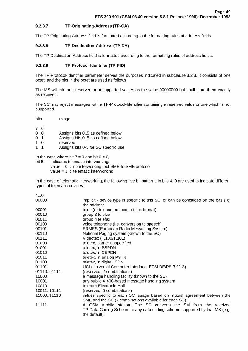
Page 49ETS 300 901 (GSM 03.40 version 5.8.1 Release 1996): December 1998
9.2.3.7 TP-Originating-Address (TP-OA)
The TP-Originating-Address field is formatted according to the formatting rules of address fields.
9.2.3.8 TP-Destination-Address (TP-DA)
The TP-Destination-Address field is formatted according to the formatting rules of address fields.
9.2.3.9 TP-Protocol-Identifier (TP-PID)
The TP-Protocol-Identifier parameter serves the purposes indicated in subclause 3.2.3. It consists of oneoctet, and the bits in the octet are used as follows:
The MS will interpret reserved or unsupported values as the value 00000000 but shall store them exactlyas received.
The SC may reject messages with a TP-Protocol-Identifier containing a reserved value or one which is notsupported.
bits usage
7 60 0 Assigns bits 0..5 as defined below0 1 Assigns bits 0..5 as defined below1 0 reserved1 1 Assigns bits 0-5 for SC specific use
In the case where bit 7 = 0 and bit 6 = 0,bit 5 indicates telematic interworking:
value = 0 : no interworking, but SME-to-SME protocolvalue = 1 : telematic interworking
In the case of telematic interworking, the following five bit patterns in bits 4..0 are used to indicate differenttypes of telematic devices:
4...000000 implicit - device type is specific to this SC, or can be concluded on the basis of
the address00001 telex (or teletex reduced to telex format)00010 group 3 telefax00011 group 4 telefax00100 voice telephone (i.e. conversion to speech)00101 ERMES (European Radio Messaging System)00110 National Paging system (known to the SC)00111 Videotex (T.100/T.101)01000 teletex, carrier unspecified01001 teletex, in PSPDN01010 teletex, in CSPDN01011 teletex, in analog PSTN01100 teletex, in digital ISDN01101 UCI (Universal Computer Interface, ETSI DE/PS 3 01-3)01110..01111 (reserved, 2 combinations)10000 a message handling facility (known to the SC)10001 any public X.400-based message handling system10010 Internet Electronic Mail10011..10111 (reserved, 5 combinations)11000..11110 values specific to each SC, usage based on mutual agreement between the
SME and the SC (7 combinations available for each SC)11111 A GSM mobile station. The SC converts the SM from the received
TP-Data-Coding-Scheme to any data coding scheme supported by that MS (e.g.the default).

Page 50ETS 300 901 (GSM 03.40 version 5.8.1 Release 1996): December 1998
If bit 5 has value 1 in an SMS-SUBMIT PDU, it indicates that the SME is a telematic device of a type whichis indicated in bits 4..0, and requests the SC to convert the SM into a form suited for that device type. Ifthe destination network is ISDN, the SC must also select the proper service indicators for connecting to adevice of that type.
If bit 5 has value 1 in an SMS-DELIVER PDU, it indicates that the SME is a telematic device of a typewhich is indicated in bits 4..0.
If bit 5 has value 0 in an SMS-DELIVER PDU, the value in bits 4..0 identifies the SM-AL protocol beingused between the SME and the MS.
Note that for the straightforward case of simple MS-to-SC short message transfer the Protocol Identifier isset to the value 0.
In the case where bit 7 = 0, bit 6 = 1, bits 5..0 are used as defined below
5....0000000 Short Message Type 0000001 Replace Short Message Type 1000010 Replace Short Message Type 2000011 Replace Short Message Type 3000100 Replace Short Message Type 4000101 Replace Short Message Type 5000110 Replace Short Message Type 6000111 Replace Short Message Type 7001000..011110 Reserved011111 Return Call Message100000..111101 Reserved111110 ME De-personalization Short Message111111 SIM Data download
A short message type 0 indicates that the ME must acknowledge receipt of the short message but maydiscard its contents.
The Replace Short Message feature is optional for the ME and the SIM but if implemented it shall beperformed as described here.
For MT short messages, on receipt of a short message from the SC, the MS shall check to see if theassociated Protocol Identifier contains a Replace Short Message Type code.
If such a code is present, then the MS will check the associated SC address and originating address andreplace any existing stored message having the same Protocol Identifier code, SC address and originatingaddress with the new short message and other parameter values. If there is no message to be replaced,the MS shall store the message in the normal way.
If a Replace Short Message Type code is not present then the MS will store the message in the normalway.
In MO short messages the SC reacts similarly but only the address of the originating MS or any othersource is checked.
A Return Call Message indicates to the MS to inform the user that a call (e.g. a telephone call) can beestablished to the address specified within the TP-OA. The RP-OA contains the address of the SC asusual. The message content (if present) gives displayable information (e.g. the number of waiting voicemessages). The message is handled in the same way as all other messages of the Replace ShortMessage Types.
The ME De-personalization Short Message is a ME-specific message which instructs the ME tode-personalities the ME (see GSM 02.22 [25]). The TP-DCS shall be set to Uncompressed, DefaultAlphabet, and Message Class 1 (ME-specific), which corresponds to a bit coding of 00010001. TheTP-UD field contains de-personalization information coded according to GSM 02.22 [25]. This informationshall not be displayed by an ME which supports the scheme. The acknowledgement to this message is aSMS-DELIVER-REPORT for RP-ACK in which the TP-User-Data shall be coded according to GSM 02.22.

Page 51ETS 300 901 (GSM 03.40 version 5.8.1 Release 1996): December 1998
SIM Data download is a facility whereby the ME must pass the short message in its entirety including allSMS elements contained in the SMS deliver to the SIM using the mechanism described in GSM 11.11.The DCS shall be set to 8 bit message class 2 (either bit coding 1111 0110 or 00010110). The entire userdata field is available for SIM Data download.
9.2.3.10 TP-Data-Coding-Scheme (TP-DCS)
The TP-Data-Coding-Scheme is defined in GSM 03.38.
9.2.3.11 TP-Service-Centre-Time-Stamp (TP-SCTS)
The TP-Service-Centre-Time-Stamp field is given in semi-octet representation, and represents the localtime in the following way:
Year: Month: Day: Hour: Minute: Second: Time ZoneDigits:(Semi-octets)
2 2 2 2 2 2 2
The Time Zone indicates the difference, expressed in quarters of an hour, between the local time andGMT. In the first of the two semi-octets, the first bit (bit 3 of the seventh octet of theTP-Service-Centre-Time-Stamp field) represents the algebraic sign of this difference (0 : positive,1 : negative).
The Service-Centre-Time-Stamp, and any other times coded in this format that are defined in thisspecification, represent the time local to the sending entity.
If the MS has knowledge of the local time zone, then any time received (e.g. Service-Centre-Time-Stamp)at the MS may be displayed in the local time rather than the time local to the sending entity. Messagesshall be stored as received without change to any time contained therein.
The Time Zone code enables the receiver to calculate the equivalent time in GMT from the othersemi-octets in the Service-Centre-Time-Stamp, or indicate the time zone (GMT, GMT+1H etc.), orperform other similar calculations as required by the implementation.
If the MS receives a non-integer value in the SCTS, it shall assume that the digit is set to 0 but shall storethe entire field exactly as received.
9.2.3.12 TP-Validity-Period (TP-VP)
9.2.3.12.1 TP-VP (Relative format)
The TP-Validity-Period comprises 1 octet in integer representation, giving the length of the validity period,counted from when the SMS-SUBMIT is received by the SC.
The representation of time is as follows:
TP-VP value Validity period value0 to 143 (TP-VP + 1) x 5 minutes (i.e. 5 minutes intervals up to 12 hours)144 to 167 12 hours + ((TP-VP -143) x 30 minutes)168 to 196 (TP-VP - 166) x 1 day197 to 255 (TP-VP - 192) x 1 week
9.2.3.12.2 TP-VP (Absolute format )
The TP-Validity Period comprises 7 octets in semi octet representation giving the absolute time of thevalidity period termination
The representation of time is identical to the representation of the TP-Service-Centre-Time-Stamp.

Page 52ETS 300 901 (GSM 03.40 version 5.8.1 Release 1996): December 1998
9.2.3.12.3 TP-VP ( Enhanced format )
The TP-Validity Period comprises 7 octets. The presence of all octets is mandatory although they may notall be used. The first octet indicates the way in which the following 6 octets are used. Any reserved/unusedbits or octets must be set to zero.
Octet 1 TP-VP functionality indicator
bit 7 Extension bitSet to 1 if the TP-VP functionality indicator is to be extended to another octet. A setting of 0indicates that there are no more TP-VP functionality indicator extension octets to follow.Any such extension octet will immediately follow the previous TP-VP functionality indicator.
bit 6 Single shot SM.Set to 1 if the SC is required to make up to one delivery attempt. The TP-Validity Period, wherepresent, will be applicable to the Single shot SM.
bits 5, 4, 3 Reserved
bits 2, 1, 0 Validity Period Format.
Value bits 2 1 0
0 0 0 No Validity Period specified
0 0 1 Validity Period is as specified for the relative case. The following octetcontains the TP-VP value as described in 9.2.3.12.1
0 1 0 Validity period is relative in integer representation and the following octetcontains the TP-VP value in the range 0 to 255 representing 0 to 255seconds. A TP-VP value of zero is undefined and reserved for future use.
0 1 1 Validity period is relative in semi-octet representation. The following 3 octetscontain the relative time in Hours Minutes and Seconds giving the length ofthe validity period counted from when the SMS SUBMIT is received by theSC. The representation of time uses the same representation as the Hours,Minutes and Seconds in the TP-Service-Centre-Time-Stamp.
1 0 0 Reserved1 0 1 Reserved1 1 0 Reserved1 1 1 Reserved
The SC will reject any Unsupported/ Reserved values received by returning the ‘TP-VP not supported’ TP-FCS value in the Submit SM Report for RP-Error
9.2.3.13 TP-Discharge-Time (TP-DT)
The TP-Discharge-Time field indicates the time at which a previously submitted SMS-SUBMIT wassuccessfully delivered to or attempted to deliver to the recipient SME or disposed of by the SC.
In the case of "transaction completed" the time shall be the time of the completion of the transaction. Inthe case of "SC still trying to transfer SM" the time shall be the time of the last transfer attempt. In thecase of "permanent or temporary error - SC not making any more transfer attempts" the time shall be thetime of either the last transfer attempt or the time at which the SC disposed of the SM according to theStatus outcome in TP-ST.
The TP-Discharge-Time is given in semi-octet representation in a format identical to the TP-SCTS.

Page 53ETS 300 901 (GSM 03.40 version 5.8.1 Release 1996): December 1998
9.2.3.14 TP-Recipient-Address (TP-RA)
The TP-Recipient-Address field indicates the address of the SME that was the destination of thepreviously submitted mobile originated short message being subject to the status report. The field isformatted according to the formatting rules of address fields.
9.2.3.15 TP-Status (TP-ST)
The TP-Status field indicates the status of a previously submitted SMS-SUBMIT and certain SMSCOMMANDS for which a Status -Report has been requested. It consists of one octet and the bits in theoctet are used as follows:
The MS will interpret any reserved values as "Service Rejected" (01100011) but shall store them exactlyas received.
bits value/usage
7 0 Bits 0..6 as defined below:
6....0 Indicate whether the previously submitted short message was successfullyforwarded to the SME, or whether an error condition has been encountered, asfollows:
Short message transaction completed0000000 Short message received by the SME0000001 Short message forwarded by the SC to the SME but the SC is
unable to confirm delivery0000010 Short message replaced by the SC
Reserved values
0000011..0001111 Reserved0010000..0011111 Values specific to each SC
Temporary error, SC still trying to transfer SM
0100000 Congestion0100001 SME busy0100010 No response from SME0100011 Service rejected0100100 Quality of service not available0100101 Error in SME0100110..0101111 Reserved0110000..0111111 Values specific to each SC

Page 54ETS 300 901 (GSM 03.40 version 5.8.1 Release 1996): December 1998
Permanent error, SC is not making any more transfer attempts
1000000 Remote procedure error1000001 Incompatible destination1000010 Connection rejected by SME1000011 Not obtainable1000100 Quality of service not available1000101 No interworking available1000110 SM Validity Period Expired1000111 SM Deleted by originating SME1001000 SM Deleted by SC Administration1001001 SM does not exist (The SM may have previously existed in
the SC but the SC no longer has knowledge of it or the SM may never have previously existed in the SC)
1001010..1001111 Reserved1010000..1011111 Values specific to each SC
Temporary error, SC is not making any more transfer attempts
1100000 Congestion1100001 SME busy1100010 No response from SME1100011 Service rejected1100100 Quality of service not available1100101 Error in SME1100110..1101001 Reserved1101010..1101111 Reserved1110000..1111111 Values specific to each SC
bits value/usage
7 1 Bits 0..6 reserved
9.2.3.16 TP-User-Data-Length (TP-UDL)
If the TP-User-Data is coded using the GSM 7 bit default alphabet, the TP-User-Data-Length field givesan integer representation of the number of characters (septets) within the TP-User-Data field to follow. If aTP-User-Data-Header field is present, then the TP-User-Data-Length value is the sum of the number ofseptets in the TP-User-Data-Header field (including any padding) and the number of septets in theTP-User-Data field which follows. See Fig. 9.2.3.24.(a).If the TP-User-Data is coded using 8-bit data, theTP-User-Data-Length field gives an integer representation of the number of octets within theTP-User-Data field to follow. If a TP-User-Data-Header field is present, then the TP-User-Data-Lengthvalue is the sum of the number of octets in the TP-User-Data-Header field and the number of octets in theTP-User-Data field which follows. See Fig. 9.2.3.24.(b).
If the TP-User-Data is coded using UCS2 [24] data, the TP-User-Data-Length field gives an integerrepresentation of the number of octets within the TP-User-Data field to follow. If a TP-User-Data-Headerfield is present, then the TP-User-Data-Length value is the sum of the number of octets in theTP-User-Data-Header field and the number of octets in the TP-User-Data field which follows.See Fig9.2.3.24.(b).
If the TP-User-Data is coded using compressed GSM 7 bit default alphabet or compressed 8 bit data orcompressed UCS2 [24] data, the TP-User-Data-Length field gives an integer representation of the numberof octets after compression within the TP-User-Data field to follow. If a TP-User-Data-Header field ispresent, then the TP-User-Data-Length value is the sum of the number of uncompressed octets in theTP-User-Data-Header field and the number of octets in the compressed TP-User-Data field whichfollows.See Fig. 9.2.3.24.(c)
For other Data Coding Schemes, see GSM 03.38.If this field is zero, the TP-User-Data field will not bepresent.

Page 55ETS 300 901 (GSM 03.40 version 5.8.1 Release 1996): December 1998
9.2.3.17 TP-Reply-Path (TP-RP)
The TP-Reply-Path is a 1-bit field, located within bit no 7 of the first octet of both SMS-DELIVER andSMS-SUBMIT, and to be given the following values:
Bit no 7: 0 TP-Reply-Path parameter is not set in this SMS-SUBMIT/DELIVER1 TP-Reply-Path parameter is set in this SMS-SUBMIT/DELIVER
Please refer to annex D for details about the Reply procedures.
9.2.3.18 TP-Message-Number (TP-MN)
The TP-Message-Number is an 8-bit field allowing an MS to refer uniquely to an SM in the SC which thatMS has previously submitted. The TP-MN value is the TP-MR value of a previously submitted SM.
9.2.3.19 TP-Command-Type (TP-CT)
The TP-Command-Type is an 8-bit field specifying the type of operation that the SC is to perform. It hasthe following values:
Value (bit 7 .. 0) Command Description Status ReportRequest Value
00000000 Enquiry relating to previously submitted shortmessage
1
00000001 Cancel Status Report Request relating to previouslysubmitted short message
0
00000010 Delete previously submitted Short Message 0
00000011 Enable Status Report Request relating to previouslysubmitted short message
0
00000100..00011111 Reserved unspecified
11100000..11111111 Values specific for each SC 1 or 0
The SC will return an RP-Error with an appropriate TP-Failure-Cause for any TP-Command value which isreserved, unsupported or invalid or the actioning of the command has failed.
The SC will return an RP-ACK if the actioning of the Command has succeeded.
A successful Enquiry will result in the SC sending a SMS-STATUS-REPORT for the SM to which theEnquiry refers. In the case where the SC has a number of SMs which have the same TP-MR, the sameTP-DA and have come from the same originating address the SC will send a SMS-STATUS-REPORT foreach SM.
In the case where a TP-Command is to Delete a previously submitted short message, the SC will send aStatus Report indicating that the SM has been deleted if the original Submit SM request requested astatus Report.
9.2.3.20 TP-Command-Data-Length (TP-CDL)
The TP-Command-Data-Length field is used to indicate the number of octets contained within theTP-Command-Data-field. If this field is set to zero, the TP-Command-Data field will not be present.
9.2.3.21 TP-Command-Data (TP-CD)
The TP-Command-Data field contains data relating to the operation requested by the MS which is to beperformed at the SC. The maximum length of this field is 157 octets. The usage and provision of theoptional TP-Command-Data field will be determined by the function selected by the TP-Command-Typefield.

Page 56ETS 300 901 (GSM 03.40 version 5.8.1 Release 1996): December 1998
9.2.3.22 TP-Failure-Cause (TP-FCS)
The TP-Failure-Cause field is used to report the reason for failure to transfer or process a short message.It consists of a single octet used as follows:
TP-FCSValue(Hex)
Meaning When used
MO MT00 - 7F Reserved
80 - 8F TP-PID errors80 Telematic interworking not supported x81 Short message Type 0 not supported x x82 Cannot replace short message x x83 - 8E Reserved8F Unspecified TP-PID error x x
90 - 9F TP-DCS errors90 Data coding scheme (alphabet) not supported x91 Message class not supported x92 - 9E Reserved9F Unspecified TP-DCS error x x
A0 - AF TP-Command ErrorsA0 Command cannot be actioned xA1 Command unsupported xA2 - AE ReservedAF Unspecified TP-Command error x
B0 TPDU not supported x xB1 - BF Reserved
C0 SC busy xC1 No SC subscription xC2 SC system failure xC3 Invalid SME address xC4 Destination SME barred xC5 SM Rejected-Duplicate SM xC6 TP-VPF not supported XC7 TP-VP not supported XC8 - CF Reserved
D0 SIM SMS storage full xD1 No SMS storage capability in SIM xD2 Error in MS xD3 Memory Capacity Exceeded XD4 SIM Application Toolkit Busy x xD5 - DF Reserved
E0 - FE Values specific to an application x x
FF Unspecified error cause x x
NOTE: Any reserved codes which are received should be treated as an unspecified errorcause.MT and MO refer to the overall mobile terminated and mobile originated services; notthe direction of transmission of TP-FCS.
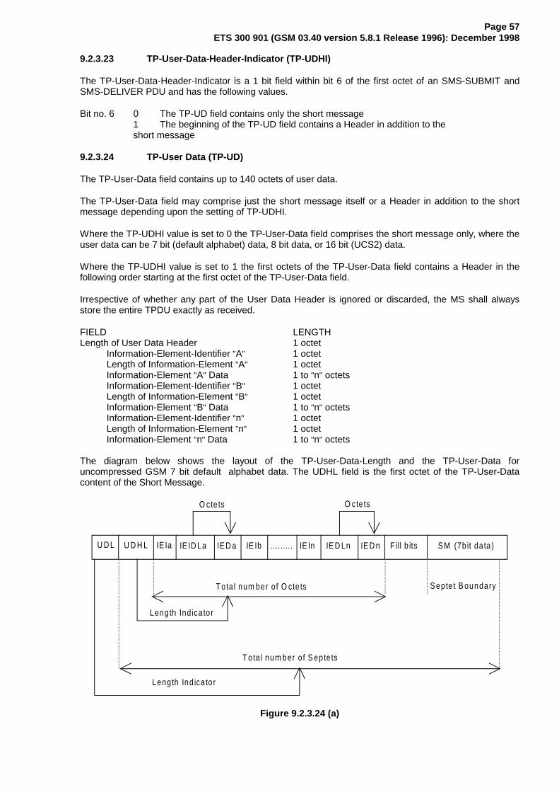
Page 57ETS 300 901 (GSM 03.40 version 5.8.1 Release 1996): December 1998
9.2.3.23 TP-User-Data-Header-Indicator (TP-UDHI)
The TP-User-Data-Header-Indicator is a 1 bit field within bit 6 of the first octet of an SMS-SUBMIT andSMS-DELIVER PDU and has the following values.
Bit no. 6 0 The TP-UD field contains only the short message1 The beginning of the TP-UD field contains a Header in addition to the short message
9.2.3.24 TP-User Data (TP-UD)
The TP-User-Data field contains up to 140 octets of user data.
The TP-User-Data field may comprise just the short message itself or a Header in addition to the shortmessage depending upon the setting of TP-UDHI.
Where the TP-UDHI value is set to 0 the TP-User-Data field comprises the short message only, where theuser data can be 7 bit (default alphabet) data, 8 bit data, or 16 bit (UCS2) data.
Where the TP-UDHI value is set to 1 the first octets of the TP-User-Data field contains a Header in thefollowing order starting at the first octet of the TP-User-Data field.
Irrespective of whether any part of the User Data Header is ignored or discarded, the MS shall alwaysstore the entire TPDU exactly as received.
FIELD LENGTHLength of User Data Header 1 octet
Information-Element-Identifier "A" 1 octetLength of Information-Element "A" 1 octetInformation-Element "A" Data 1 to "n" octetsInformation-Element-Identifier "B" 1 octetLength of Information-Element "B" 1 octetInformation-Element "B" Data 1 to "n" octetsInformation-Element-Identifier "n" 1 octetLength of Information-Element "n" 1 octetInformation-Element "n" Data 1 to "n" octets
The diagram below shows the layout of the TP-User-Data-Length and the TP-User-Data foruncompressed GSM 7 bit default alphabet data. The UDHL field is the first octet of the TP-User-Datacontent of the Short Message.
U D L U D H L IE Ia IE D a IE Ib ......... IE In IE D Ln IE D n F ill b its S M (7b it da ta )
S epte t B oundaryT ota l num ber of O cte ts
Length Ind ica to r
T ota l num ber o f S epte ts
Length Indica to r
O cte tsO cte ts
IE ID La
Figure 9.2.3.24 (a)

Page 58ETS 300 901 (GSM 03.40 version 5.8.1 Release 1996): December 1998
The diagram below shows the layout of the TP-User-Data-Length and the TP-User-Data foruncompressed 8 bit data or uncompressed UCS2 data. The UDHL field is the first octet of the TP-User-Data content of the Short Message.
U D L U D H L IE Ia IED a IE Ib . ....... . IE In IED Ln IE D n
O ctet B oundaryTo ta l num ber of O cte ts
Length Indica to r
T otal num ber of O ctets
Length Indica tor
O c te tsO cte ts
IE ID LaS M (8 b it data
or U C S -2 data)
Figure 9.2.3.24 (b)
The diagram below shows the layout of the TP-User-Data-Length and the TP-User-Data for compressedGSM 7 bit default alphabet data, compressed 8 bit data or compressed UCS2 data. The UDHL field is thefirst octet of the TP-User-Data content of the Short Message.
U D L U D H L IE Ia IED a IE Ib ...... .. . IE In IED Ln IED n
O ctet B oundaryTota l num ber of O cte ts
Length Indica to r
T otal num ber of O cte ts
Length Indica tor
O c te tsO cte ts
IE ID La C om pressed S M (oc te ts)
Figure 9.2.3.24 (c)
The definition of the TP-User-Data-Length field which immediately precedes the "Length of User DataHeader" is unchanged and will therefore be the total length of the TP-User-Data field including the Header,if present. (see 9.2.3.16)
The "Length-of-Information-Element" fields shall be the integer representation of the number of octetswithin its associated "Information-Element-Data" field which follows and shall not include itself in its countvalue.
The "Length-of-User-Data-Header" field shall be the integer representation of the number of octets withinthe "User-Data-Header" information fields which follow and shall not include itself in its count or any fill bitswhich may be present (see text below).

Page 59ETS 300 901 (GSM 03.40 version 5.8.1 Release 1996): December 1998
Information Elements may appear in any order and need not necessarily follow the order used in thisspecification. If Information Elements are duplicated (either with the same or different content) then thecontents of the last occurrence of the Information Element shall be used. If the length of the User DataHeader overall is such that there appear to be too few or too many octets in the final Information Elementthen the whole User Data Header shall be ignored.
If any reserved values are received within the content of any Information Element then that part of theInformation Element shall be ignored.
The Information Element Identifier octet shall be coded as follows:
VALUE (hex) MEANING00 Concatenated short messages01 Special SMS Message Indication02 Reserved03 Value not used to avoid misinterpretation as <LF> character04 Application port addressing scheme, 8 bit address05 Application port addressing scheme, 16 bit address06 SMSC Control Parameters07 UDH Source Indicator
08-7F Reserved for future use80 - 9F SME to SME specific useA0 - BF Reserved for future useC0 - DF SC specific useE0 - FF Reserved for future use
A receiving entity shall ignore (i.e. skip over and commence processing at the next information element)any information element where the IEI is Reserved or not supported. The receiving entity calculates thestart of the next information element by looking at the length of the current information element andskipping that number of octets.
The SM itself may be coded as 7, 8 or 16 bit data.
If 7 bit data is used and the TP-UD-Header does not finish on a septet boundary then fill bits are insertedafter the last Information Element Data octet so that there is an integral number of septets for the entireTP-UD header. This is to ensure that the SM itself starts on an septet boundary so that an earlierPhase mobile will be capable of displaying the SM itself although the TP-UD Header in the TP-UD fieldmay not be understood.
It is optional to make the first character of the SM itself a Carriage Return character encoded according tothe default 7 bit alphabet so that earlier Phase mobiles, which do not understand the TP-UD-Header, willover-write the displayed TP-UD-Header with the SM itself.
If 16 bit (USC2) data is used then padding octets are not necessary. The SM itself will start on an octetboundary.
If 8 bit data is used then padding is not necessary. An earlier Phase mobile will be able to display the SMitself although the TP-UD header may not be understood.
It is also possible for mobiles not wishing to support the TP-UD header to check the value of the TP-UDHIbit in the SMS-Deliver PDU and the first octet of the TP-UD field and skip to the start of the SM and ignorethe TP-UD header.
9.2.3.24.1 Concatenated Short Messages
This facility allows short messages to be concatenated to form a longer message.
In the case of uncompressed 8-bit data, the maximum length of the short message within the TP-UD fieldis 134 (140-6) octets.
In the case of uncompressed GSM Default 7 bit data, the maximum length of the short message withinthe TP-UD field is 153 (160-7) characters.

Page 60ETS 300 901 (GSM 03.40 version 5.8.1 Release 1996): December 1998
In the case of 16 bit uncompressed USC2 data, the maximum length of the short message within theTP-UD field is 67 ((140-6)/2) characters. A UCS2 character must not be split in the middle; if the length ofthe User Data Header is odd, the maximum length of the whole TP-UD field is 139 octets.
In the case of compressed GSM Default alphabet 7 bit data, 8 bit data or UCS2 the maximum length ofthe compressed short message within the TP-UD field is 134 ( 140-6) octets including the CompressionHeader and Compression Footer, both or either of which may be present ( See subclause 3.9).
The maximum length of an uncompressed concatenated short message is 39015 (255*153) defaultalphabet characters, 34170 (255*134) octets or 17085 (255*67) UCS2 characters.
The maximum length of a compressed concatenated message is 34170 (255*134) octets including theCompression Header and Compression Footer ( see subclause 3.9 and Fig 9.2.3.24.1(a) below.
Compression FooterCompressed Data (CD)Compression Header
CDCHTP-UDH CDTP-UDH CD CFTP-UDH
First segment Intermediate segments Final segment
Segmentation / De-segmentation
Figure 9.2.3.24.1.(a) Concatenation of a Compressed short message
The Information-Element-Data field contains information set by the application in the SMS-SUBMIT sothat the receiving entity is able to re-assemble the short messages in the correct order. Eachconcatenated short message contains a reference number which together with the originating addressand Service Centre address allows the receiving entity to discriminate between concatenated shortmessages sent from different originating SMEs and/or SCs.
The TP elements in the SMS-SUBMIT PDU, apart from TP-MR, TP-UDL and TP-UD, should remainunchanged for each SM which forms part of a concatenated SM, otherwise this may lead to irrationalbehaviour.
The Information-Element-Data octets shall be coded as follows.
Octet 1 Concatenated short message reference numberThis octet shall contain a modulo 256 counter indicating the reference number for aparticular concatenated short message. This reference number shall remain constantfor every short message which makes up a particular concatenated short message.
Octet 2 Maximum number of short messages in the concatenated short message.This octet shall contain a value in the range 0 to 255 indicating the total number ofshort messages within the concatenated short message. The value shall start at 1 andremain constant for every short message which makes up the concatenated shortmessage. If the value is zero then the receiving entity shall ignore the wholeInformation Element.

Page 61ETS 300 901 (GSM 03.40 version 5.8.1 Release 1996): December 1998
Octet 3 Sequence number of the current short message.This octet shall contain a value in the range 0 to 255 indicating the sequence numberof a particular short message within the concatenated short message. The value shallstart at 1 and increment by one for every short message sent within the concatenatedshort message. If the value is zero or the value is greater than the value in octet 2 thenthe receiving entity shall ignore the whole Information Element.
9.2.3.24.2 Special SMS Message Indication
There are three levels of "Message Waiting" indication provided within this specification. The first level isto set the Protocol Identifier to "Return Call message", which indicates that a message is waiting andrelies on the text of the message to supply the detail. The second level uses the Data Coding Schemewith or without Return Call Message (see GSM 03.38) to indicate the type of message waiting andwhether there are some messages or no messages. The third level is described here, and provides themaximum detail level for analysis by the mobile, i.e. an indication of the number and type of messageswaiting in systems connected to the PLMN. This third level is provided for future flexibility, as it cannotimmediately be used without compatibility problems with the earliest Phase mobiles. It is envisaged thatthis scheme can start to be used once mobiles supporting TP-UDH become widely available.
This information may be stored by the MS in a form other than an SMS message, for example an indicatormay be shown if the number of messages is non-zero or removed if the number of messages is zero. TheMS may also store actual number of messages waiting and provide some other MMI to access thisinformation. Text may be included by the SMS Service Centre for backward compatibility with the earliestPhase mobiles and the Data Coding Scheme may also be used to convey this information in parallel forbackward compatibility with "middle" Phase mobiles (which support the use of Data Coding Scheme forMessage Waiting Indication but not the use of TP-UDH for Message Waiting Indication).
The information-Element octets shall be coded as follows:
Octet 1 Message Indication type and Storage
Bit 7 Indicates whether or not the message shall be stored.
Bit 70 Discard message after updating indication1 Store message
In the event of a conflict between this setting and the setting of the Data Coding Scheme (seeGSM 03.38) then the message shall be stored if either the DCS indicates this, or Octet 1above indicates this.
Bits 6..0 show the message indication type
000 0000 Voice Message Waiting000 0001 Fax Message Waiting000 0010 Electronic Mail Message Waiting000 0011 Other Message Waiting (see GSM 03.38 for definition of "other")
Other values are reserved for future use
Octet 2 Message CountThis octet shall contain a value in the range 0 to 255 indicating the number of messages ofthe type specified in Octet 1 waiting. The value 255 shall be taken to mean 255 or greater. Inthe event of a conflict between this setting and the setting of the Data Coding Scheme (seeGSM 03.38) then the Message Count in the TP-UDH shall override the indication in theTP-DCS.

Page 62ETS 300 901 (GSM 03.40 version 5.8.1 Release 1996): December 1998
If more than one type of message is required to be indicated within one SMS message, then further octetsmust be used, as in the following example:
[00] TP-UDL [1E] (30 decimal septets)
[01] Length of TP-UDH [08]
[02] IEI = Special SMS Message Indication [01]
[03] Length = 02
[04] Octet 1 = Voice Mail, do not store [00]
[05] Octet 2 = 04 Messages
[06] IEI = Special SMS Message Indication [01]
[07] Length = 02
[08] Octet 1 = Fax Mail, Store [81]
[09] Octet 2 = 02 Messages
+ 5 Fill bits
+ 15 seven-bit character message text
The Total number of bits is 210.
9.2.3.24.3 Application Port Addressing 8 bit address
This facility allows short messages to be routed to one of multiple applications in the TE (terminalequipment), using a method similar to TCP/UDP ports in a TCP/IP network. An application entity isuniquely identified by the pair of TP-DA/TP-OA and the port address. The port addressing is transparent tothe transport, and also useful in Status Reports.
The total length of the IE is 2 octets
octet 1 Destination portThis octet contains a number indicating the receiving port, i.e. application, in thereceiving device.
octet 2 Originator portThis octet contains a number indicating the sending port, i.e. application, in thesending device.
The port range is up to 255 using 8 bit addressing space. The Integer value of the port number ispresented as in GSM 03.40 subclause 9.1.2.1.
VALUE (port number) MEANING0 - 239 Reserved240 - 255 Available for allocation by applications
A receiving entity shall ignore (i.e. skip over and commence processing at the next information element)any information element where the value of the Information-Element-Data is Reserved or not supported.
9.2.3.24.4 Application Port Addressing 16 bit address
This facility allows short messages to be routed to one of multiple applications in the TE (terminalequipment), using a method similar to TCP/UDP ports in a TCP/IP network. An application entity isuniquely identified by the pair of TP-DA/TP-OA and the port address. The port addressing is transparent tothe transport, and also useful in Status Reports.

Page 63ETS 300 901 (GSM 03.40 version 5.8.1 Release 1996): December 1998
The total length of the IE is 4 octets
octet 1,2 Destination port
These octets contain a number indicating the receiving port, i.e. application, in thereceiving device.
octet 3,4 Originator portThese octets contain a number indicating the sending port, i.e. application, in thesending device.
The port range is up to 65535 using 16 bit addressing space. The Integer value of the port number ispresented as in GSM 03.40 subclause 9.1.2.1.
VALUE (port number) MEANING0 - 15999 Reserved16000 - 16999 Available for allocation by applications17000 - 65535 Reserved
A receiving entity shall ignore (i.e. skip over and commence processing at the next information element)any information element where the value of the Information-Element-Data is Reserved or not supported.
9.2.3.24.5 SMSC Control Parameters
The facility enables the SMS protocol headers to be expanded using a flexible method. It may be used tocontrol the SMSC, but is also passed transparently to the receiving mobile. The Information Element mustbe present in every short message affected by it, i.e. in every short message in a concatenated message.
The Information Element data octets shall be coded as follows:
octet 1 Selective Status ReportThis facility is used to control the creation of Status Reports, depending on the errorcode of the particular message. It is also used by the sending entity to requestinclusion of the original UDH into the Status Report. In this case the original UDH mustbe separated from the rest of the UDH using the Source Indicator. The TP-SRR mustbe set in order for the Selective Status Report to be enabled. The bits are defined asfollows
bit 00 No Status Report for short message transaction completed1 Status Report for short message transaction completed
bit 10 No Status Report for permanent error when SC is not making any more transfer
attempts1 Status Report for permanent error when SC is not making any more transfer attempts
bit 20 No Status Report for temporary error when SC is not making any more transfer
attempts1 Status Report for temporary error when SC is not making any more transfer attempts
bit 30 No Status Report for temporary error when SC is still trying to transfer SM1 Status Report for temporary error when SC is still trying to transfer SM
bits 4 and 5reserved for future use.
bit 60 No activation1 A Status Report generated by this Short Message, due to a permanent error or last
temporary error, cancels the SRR of the rest of the Short Messages in a concatenated

Page 64ETS 300 901 (GSM 03.40 version 5.8.1 Release 1996): December 1998
message. This feature can only be used where a SC is aware of the segmentation of aconcatenated SM and is therefore an implementation matter.
bit 70 Do not include original UDH into the Status Report1 Include original UDH into the Status Report
9.2.3.24.6 UDH Source Indicator
The facility is used to separate the UDH of the original message, a UDH created by the SMSC, and aUDH provided by the original receiving entity. The Source Indicator is placed in front of the contentinserted by the source. The indicated content (one or more Information-Elements) ends at the next UDH-Source-Indicator, or at the end of the UDH. The Separator is intended to be used especially in StatusReports, but can also be used by the SMSC to add information into Short Message (for example Messagewaiting). The default content for a UDH in a SMS-DELIVERY is the headers inserted by the sendingdevice, and the default content for a UDH in a SMS-STATUS-REPORT is the headers copied from theSMS-DELIVERY-REPORT.
Values of octet:
01 The following part of the UDH is created by the original sender (valid in case of StatusReport)
02 The following part of the UDH is created by the original receiver (valid in case of StatusReport)
03 The following part of the UDH is created by the SMSC (can occur in any message or report)
9.2.3.25 TP-Reject-Duplicates (TP-RD)
The TP-Reject-Duplicates is a 1 bit field located within bit 2 of the first octet of SMS-SUBMIT and has thefollowing values.
Bit no. 2: 0 Instruct the SC to accept an SMS-SUBMIT for an SM still held in theSC which has the same TP-MR and the same TP-DA as a previously submitted SM from the same OA.
1 Instruct the SC to reject an SMS-SUBMIT for an SM still held in theSC which has the same TP-MR and the same TP-DA as the previously submitted SM from the same OA. In this case an appropriate TP-FCS value will be returned in the SMS-SUBMIT-REPORT.
9.2.3.26 TP-Status-Report-Qualifier (TP-SRQ)
The TP-Status-Report-Qualifier is a 1 bit field located within bit 5 of the first octet ofSMS-STATUS-REPORT and has the following values
Bit no. 5: 0 The SMS-STATUS-REPORT is the result of a SMS-SUBMIT.1 The SMS-STATUS-REPORT is the result of an SMS-COMMAND e.g.
an Enquiry.
9.2.3.27 TP-Parameter-Indicator (TP-PI)
The TP-Parameter-Indicator comprises a number of octets between 1 and n where each bit when set to a1 indicates that a particular optional parameter is present in the fields which follow. The TP-PI is presentas part of the RP-User-Data in the RP-ACK for both the SMS-DELIVER TPDU and the SMS-SUBMITTPDU.

Page 65ETS 300 901 (GSM 03.40 version 5.8.1 Release 1996): December 1998
The structure of the TP-PI is as follows:
Octet 1
bit 7 bit 6 bit 5 bit 4 bit 3 bit 2 bit 1 bit 0
Extensionbit
Reserved Reserved Reserved Reserved TP-UDL TP-DCS TP-PID
The most significant bit in octet 1 and any other TP-PI octets which may be added later is reserved as anextension bit which when set to a 1 will indicate that another TP-PI octet follows immediately afterwards.
If the TP-UDL bit is set to zero then by definition then neither the TP-UDL field or the TP-UD field can bepresent.If a Reserved bit is set to "1" then the receiving entity shall ignore the setting. The setting of this bit willmean that additional information will follow the TP-User-Data, so a receiving entity shall discard any octetsfollowing the TP-User-Data.
9.3 Service provided by the SM-RL
9.3.1 General
The Short Message Relay Layer (SM-RL) provides a service to the Short Message Transfer Layer(SM-TL). This service enables the SM-TL to send Transfer Protocol Data Units (TPDUs) to its peer entity,receive TPDUs from its peer entity and receive reports about earlier requests for TPDUs to be transferred.
In order to keep track of TPDUs and reports about those TPDUs, primitives between the SM-TL andSM-RL contain a Short Message Identifier (SMI), which is a reference number for the TPDU associatedwith the primitive. This Short Message Identifier is not carried via the SM-RL protocol of subclause 9.3.2. Itis carried via the relay layer service between the SC and GMSC. It is also carried by SM-RL ofGSM 04.11, between the visited MSC and MS. The parameter is not carried by MAP but is mapped to andfrom the TCAP dialogue Identifier (see CCITT recommendation Q.771, "Blue Book") at the GMSC and thevisited MSC (therefore the Message Identifier at the SC/GMSC interface is not the same as at the visitedMSC/MS interface).
The SM-RL communicates with its peer entity by the protocol described in the following sections.
9.3.2 Protocol element repertoire at SM-RL
Different protocols are required between different pairs of SM-RL entities. Those are described in otherGSM specifications. This subclause gives a survey of the different information elements which have to beconveyed between those entities. (Note that the notation of the protocol and information elements mayvary between different GSM specifications).
The SM-RL comprises the following 6 protocol elements:
RP-MO-DATA for transferring a TPDU from MS to SCRP-MT-DATA for transferring a TPDU from SC to MSRP-ACK for acknowledging an RP-MO-DATA, an RP-MT-DATA or an
RP-SM-MEMORY-AVAILABLERP-ERROR for informing of an unsuccessful RP-MO-DATA or an RP-MT-DATA
transfer attemptRP-ALERT-SC for alerting the SC that the MS has recovered operation (information
sent from the HLR to the SC)RP-SM-MEMORY-AVAILABLE for notifying the network that the MS has memory available to
accept one or more short messages (information sent from the MS tothe HLR)

Page 66ETS 300 901 (GSM 03.40 version 5.8.1 Release 1996): December 1998
9.3.2.1 RP-MO-DATA
Basic elements of the RP-MO-DATA type.
Abbr. Reference P 1) DescriptionRP-OA RP-Originating-Address ++- Address of the originating MS.
RP-DA RP-Destination-Address -++ Address of the destination SC.
RP-UD RP-User-Data +++ Parameter containing the TPDU
1) Provision on the links SC<->MSC, MSC<->MSC and MSC<->MS indicated by "xxx", where x maybe either "+" or "-", dependent on whether the parameter is mandatory or not on the respective link.
9.3.2.2 RP-MT-DATA
Basic elements of the RP-MT-DATA type.
Abbr. Reference P 1) DescriptionRP-PRI RP-Priority-Request +-- Parameter indicating whether or not the short
message transfer should be stopped if theoriginator SC address is already contained inthe MWD.
RP-MMS RP-More-Messages-To-Send OO- Parameter indicating that there are moremessages waiting in the SC
RP-OA RP-Originating-Address +++ Address of the originating SC.
RP-DA RP-Destination-Address ++- Address of the destination MS.
RP-UD RP-User-Data +++ Parameter containing the TPDU
1) Provision on the links SC<->MSC, MSC<->MSC and MSC<->MS indicated by "xxx", where x maybe "+", "-" or "O", dependent on whether the parameter is mandatory, not present or optional on therespective link.
9.3.2.3 RP-ACK
The RP-ACK contains the RP-User-Data which is a parameter containing the TPDU (see 9.2.2.1a and9.2.2.2a).

Page 67ETS 300 901 (GSM 03.40 version 5.8.1 Release 1996): December 1998
9.3.2.4 RP-ERROR
Basic elements of the RP-ERROR type.
Abbr. Reference P 1) DescriptionRP-MSI RP-MW-Set-Indication +-- Parameter indicating whether or not the MWI has
been up-dated. 2)
RP-CS RP-Cause +++ Parameter identifying the error type. TheRP-Cause parameter gives the reason why ashort message transfer attempt fails. In practicethree relay layer protocols are used - SC toGMSC/IWMSC (see GSM 03.47), MAP (seeGSM 09.02) and via the radio interface (seeGSM 04.11)
RP-MSIsdn RP-international--MS-ISDN-number
+-- MSIsdn-Alert of the MS, see subclause 3.2.7 3)
RP-UD RP-User-Data OO O Parameter containing a TPDU
1) Provision on the links SC<->MSC, MSC<->MSC and MSC<->MS indicated by "xxx",where x may be "+", "-" or "O" dependent on whether the parameter is mandatory, notpresent or optional on the respective link.
2) Only present when the RP-ERROR is transferred from the SMS-IWMSC to the SC.
3) Only present when the RP-MT-DATA transfer attempt failed because the MS is not reachable orbecause the MS memory capacity was exceeded and the MSIsdn-Alert is different from the MSIsdnused by the SC to address the recipient MS
9.3.2.5 RP-ALERT-SC
Basic elements of the RP-ALERT-SC type:
Abbr. Reference P 1) DescriptionRP-MSIsdn RP-International-MS-ISDN-Num
berM MSIsdn of the MS.
1) Provision; Mandatory (M).
9.3.2.6 RP-SM-MEMORY-AVAILABLE
Basic elements of the RP-SM-MEMORY-AVAILABLE type:
Abbr. Reference P 1) DescriptionRP-IMSI RP-International-Mobile-Subscri
ber-Identity++- IMSI of the MS.
1) Provision on the links HLR<->VLR, VLR<->MSC and MSC<->MS indicated by "xxx", where x maybe either "+" or "-", dependent on whether the parameter is mandatory or not present on therespective link.

Page 68ETS 300 901 (GSM 03.40 version 5.8.1 Release 1996): December 1998
10 Fundamental procedures within the point-to-point SMS
The point-to-point SMS comprises 3 fundamental procedures:
1) Short message mobile terminated. This procedure consists of all necessary operations to:
a) transfer a short message or status report from the SC to the MS;b) return a report to the SC, containing the result of the message transfer attempt.
2) Short message mobile originated. This procedure consists of all necessary operations to:
a) transfer a short message from the MS to the SC;b) return a report to the MS, containing the result of the message transfer attempt.
3) Transfer of an Alert. This procedure consists of all necessary operations for an HLR or a VLR toinitiate a transfer of an Alert to a specific SC, informing the SC that the MS has recoveredoperation.
GSM 09.02 defines operations necessary for the provision of the Short Message Service point-to-point.The operations defined in clause 10 describe the requirement that the Short Message Service puts uponthe network functionality. If discrepancies exist in nomenclature, it is the GSM 09.02 that will be thereference.
Annex C indicates the flow of primitives and parameters during the short message transfer between theSC and the MS. Both the Mobile terminated and the Mobile originated cases are covered.
10.1 Short message mobile terminated
The entities involved in this procedure are depicted in figure 03.40/14.
S C S M C -G M S C M S C M Sx
H LR V LR
NOTE: Since the short message mobile terminated procedure covers the functionality required atSM-RL for transferring TPDUs from SC to MS, the procedure described covers both shortmessage (SMS-DELIVER) and status report (SMS-STATUS-REPORT) transfer. The term"short message transfer" therefore, in this section, covers both cases.
Figure 03.40/14: Interfaces involved in the Short message mobile terminated procedure.GSM 03.02. X is the interface between an MSC and an SC as defined in clause 5.
In figure 03.40/15, sequence diagrams are shown for the following basic situations of short messagemobile terminated transfer attempt:
- Successful short message transfer;- Short message transfer attempt failing due to error at the SMS-GMSC;- Short message transfer attempt failing due to negative outcome of HLR information retrieval;- Short message transfer attempt failing due to error at the MSC;- Short message transfer attempt failing due to negative outcome of VLR information retrieval;- Short message transfer attempt failing due to erroneous message transfer on the radio path.
References to the relevant specifications of the different operations are given in clause 4.

Page 69ETS 300 901 (GSM 03.40 version 5.8.1 Release 1996): December 1998
S C S M S -G M S C H LR M S C V LR
1.a M essage
transfer
2. SendRoutingInfo
ForShortM sg
4a. ForewardShortM essage
5. sendInfoFor-
M T-S M S
6. M essage transfer
4b. D elivery
report
1b. D elivery
report
4b. Delivery report
O peration invocation o r m essage transfer.
S uccessfu l opera tion invoca tion o r m essage transfer inc lud ing repo rt.
M S
-
Figure 03.40/15a): Successful short message transfer attempt

Page 70ETS 300 901 (GSM 03.40 version 5.8.1 Release 1996): December 1998
S C S M S -G M S C H LR M S C V LR M S
1.a M essage
transfer
1c. Fa ilu re
report
O peration invoca tion or m essage transfer
E rror report
Figure 03.40/15b): Short message transfer attempt failing due to error at the SMS-GMSC
S C S M S -G M S C H LR M S C V LR M S
1.a M essage
transfer
2 . sendR outingInfo
ForS hortM sg
1c. Failure
report
In form SC
O pera tion invoca tion o r m essage trans fer.E rro r re po rt
-
U nsu ccess fu l op era tion invoca tion ro m essage tran s fer inc lud ing repo rt
Figure 03.40/15c): Short message transfer attempt failing due to negative outcome ofHLR information retrieval
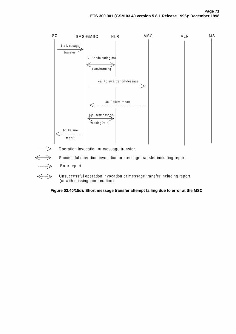
Page 71ETS 300 901 (GSM 03.40 version 5.8.1 Release 1996): December 1998
SC S M S-G M S C H LR M SC V LR M S
1.a M essage
trans fe r
2 . S endR outing In fo
F o rS ho rtM sg
4a. F o rew a rdS h ortM essage
1c . F a ilu re
rep ort
4c. F a ilu re repo rt
(3a . se tM essa ge-
W aitingD ata)
O pe ra tion invoca tion or m essage trans fe r.
Success fu l ope ra tion invocation o r m essage transfe r inc lud ing report.
U nsuccess fu l opera tion invoca tion or m essage trans fe r inc lud ing repo rt.
E rro r repo rt
(o r w ith m iss ing con firm ation )
-
Figure 03.40/15d): Short message transfer attempt failing due to error at the MSC

Page 72ETS 300 901 (GSM 03.40 version 5.8.1 Release 1996): December 1998
S C S M S -G M S C H LR M S C V LR M S
O pera tion invoca tion or m essage transfe r.
S uccessfu l ope ra tion invocation o r m essage transfe r inc lud ing report.
U nsuccessfu l opera tion invoca tion or m essage transfe r inc lud ing report.
E rro r report
(or w ith m iss ing confirm a tion )
1.a M essage
transfer
2 . S endR outingIn fo
ForS hortM sg
4a. Forew ardS hortM essage
5. sendIn foFor-
M T-S M S
4c. Fa ilu re report
(3a . se tM essage-
W aitingD ata)
1c. Fa ilu re
report
-
Figure 03.40/15e): Short message transfer attempt failing due to negative outcome ofVLR information retrieval

Page 73ETS 300 901 (GSM 03.40 version 5.8.1 Release 1996): December 1998
S C S M S -G M S C H LR M S C V LR M S
O peration invocation o r m essage transfer.
S uccessfu l ope ra tion invoca tion or m essage transfe r inc lud ing report.
U nsuccessfu l operation invoca tion o r m essage transfer inc lud ing report.
E rro r report
(o r w ith m iss ing confirm a tion )
1.a M essage
transfer
2 . S endR outingIn fo
ForS hortM sg
4a. Forew ardS hortM essage
4c. Fa ilu re report
(3a. se tM essage-
W aitingD ata)
1c. Fa ilu re
report
5 . sendIn foFor-
M T-S M S
6. M essage trans fer
-
Figure 03.40/15f): Short message transfer attempt failing due to erroneous message transferon the radio path
Operation 1: Message transfer SC -> SMS-GMSC
This operation is used to transfer a short message from an SC to an SMS-GMSC.
The operation consists of:
- the transfer of a message containing the TPDU from the SC to the SMS-GMSC (see "1a. Messagetransfer" in figure 03.40/15); and
- the return of either a "Failure report" (see 1c. in figure 03.40/15) or a "Delivery report" (see 1b. infigure 03.40/15).

Page 74ETS 300 901 (GSM 03.40 version 5.8.1 Release 1996): December 1998
"Failure report" is returned to the SC when the SMS-GMSC has received indication from another entity(MSC or HLR) the procedure was unsuccessful. The error indications which the SMS-GMSC may receivefrom the MSC, HLR, VLR or MS enable the SMS-GMSC to return one of the error indications given insubclause 3.3 back to the SC.
Operation 2: sendRoutingInfoForShortMsg
The operation is an interrogation of the HLR by the SMS-GMSC to retrieve information necessary toforward the short message.
Operation 3: setMessageWaitingData
The operation provides a means for the SMS-GMSC to request the HLR to add an SC address to theMWD, and is activated when the SMS-GMSC receives an absent subscriber indication from the MSC orwhen the SMS-GMSC receives a failure report for a short message transfer with cause MS MemoryCapacity Exceeded. The Return Result optionally contains the MSIsdn-Alert.
The operation consists of:
- the transfer of a message, containing the MSISDN of the MS to which the short message wasaddressed, the SC-address and the cause (Absent Subscriber or MS memory capacity exceeded)for setting the MWD, from the SMS-GMSC to the HLR (see 3. in figure 03.40/15).
Operation 4: forwardShortMessage
The operation provides a means for the SMS-GMSC to transfer a short message to the MSC at which theMS is currently located.
The operation works in tandem with the forwarding of the short message from the MSC to the MS. Thus,the outcome of the operation comprises either success, i.e. that the message has been delivered to theMS; or a failure that may be caused by several reasons, e.g. failure in the transfer SMS-GMSC -> MSC,MS being detached, or no paging response.
Operation 5: sendInfoForMT-SMS
The operation provides a means for the MSC to retrieve subscriber information from VLR for mobileterminated short message transfer. The operation may be associated with an authentication procedure, asshown in figure 03.40/16. Unsuccessful retrieval (e.g. absent subscriber) is indicated by a cause indicationto the SMS-GMSC.
An overall depiction of how operation 5 interacts with signalling on the radio path is given infigure 03.40/16.
It should be noted that the MNRF setting is implicitly carried out when the message transfer is denied dueto IMSI DETACH.
Operation 6: Message transfer MSC -> MS
The operation is used to transfer a short message from the MSC to the MS.
If the transfer is not successful, e.g. due to the MS losing radio coverage after having successfullyauthenticated, a failure report (RP-ERROR) is returned to the SMS-GMSC. In this case, MWD and MCEFwill be updated only for the case where the transfer fails with cause MS Memory Capacity Exceeded.
If the MS notifies the network that the MS has been unable to accept a short message because itsmemory capacity has been exceeded, then the ME will set the memory capacity Exceeded Notificationflag if present.

Page 75ETS 300 901 (GSM 03.40 version 5.8.1 Release 1996): December 1998
Operation 7: InformSC
The operation is used to transfer the MSIsdn-Alert from the HLR to the SMS-GMSC in case of the errorAbsent Subscriber given as an answer to the operation SendRoutingInfoForSM.
SC SMS-GMSC HLR MSC VLR MS
4a. forwardShortMessage −−−−−−−−−−−−−−−−−−−−−−−−−−−−−−−−−−−−> 5a. sendInfoFor- −−−−−−−−−−−−−−−−> MT-SMS Page 1) <−−−−−−−−−−−−−−−> Authent. 1) <−−−−−−−−−−−−−−−> 5b. sendInfoFor- <−−−−−−−−−−−−−−−− MT-SMS (Ack) 6. Message transfer (correct) <−−−−−−−−−−−−−−−−−−−−−−−−−−−−−−−−−> 4b. Delivery report <−−−−−−−−−−−−−−−−−−−−−−−−−−−−−−−−−−−−
−−−−−−−−−> : Operation invocation or message transfer<−−−−−−−−> : Successful operation invocation or message transfer incl. report
References:
1) : Described in GSM 04.08 and GSM 09.02
Figure 03.40/16a): "Send information for MT SMS " procedure; error free case

Page 76ETS 300 901 (GSM 03.40 version 5.8.1 Release 1996): December 1998
SC SMS-GMSC HLR MSC VLR MS
4a. forwardShortMessage −−−−−−−−−−−−−−−−−−−−−−−−−−−−−−−−−−−−> 5a. sendInfoFor- −−−−−−−−−−−−−−−−> MT-SMS 5c. Failure <- - - - - - - - report 4c. Failure report <- - - - - - - - - - - - - - - - - - 3a. setMessage- −−−−−−−−−−−−−−−−−> WaitingData
−−−−−−−−−> : Operation invocation or message transfer - - - -> : Error report
Figure 03.40/16b): "Send information for MT SMS " procedure;erroneous case: absent subscriber (e.g. IMSI DETACH)

Page 77ETS 300 901 (GSM 03.40 version 5.8.1 Release 1996): December 1998
SC SMS-GMSC HLR MSC VLR MS
4a. forwardShortMessage −−−−−−−−−−−−−−−−−−−−−−−−−−−−−−−−−−−−> 5a. sendInfoFor- −−−−−−−−−−−−−−−−> MT-SMS Page 1) −−−−−−−−−−−−−−−−> 5c. Paging or <- - - - - - - - auth. failure 4c. Failure report <- - - - - - - - - - - - - - - - - - 3a. setMessage- −−−−−−−−−−−−−−−−−> WaitingData
−−−−−−−−−> : Operation invocation or message transfer - - - -> : Error report
References:
1) : Described in GSM 04.08 and GSM 09.02
Figure 03.40/16c): "Send information for MT SMS " procedure;erroneous case: Absent subscriber (e.g. no paging response)

Page 78ETS 300 901 (GSM 03.40 version 5.8.1 Release 1996): December 1998
SC SMS-GMSC HLR MSC VLR MS
4a. forwardShortMessage −−−−−−−−−−−−−−−−−−−−−−−−−−−−−−−−−−−−> 5a. sendInfoFor- −−−−−−−−−−−−−−−−> MT-SMS Page 1) <−−−−−−−−−−−−−−−−> Authent. 1) <- - - - - - - -> (incorr. resp.) 5c. Paging or <- - - - - - - - auth. failure 4c. Failure report <- - - - - - - - - - - - - - - - - -
−−−−−−−−−> : Operation invocation or message transfer - - - -> : Error report<- - - -> : Unsuccessful operation invocation or message transfer including error report
(or with missing confirmation)
References:
1) : Described in GSM 04.08 and GSM 09.02
Figure 03.40/16d): "Send information for MT SMS " procedure; incorrect authentication

Page 79ETS 300 901 (GSM 03.40 version 5.8.1 Release 1996): December 1998
10.2 Short message mobile originated
The entities involved in this procedure is depicted in figure 03.40/17.
S C S M S -IW M S C M S C M Sx
V LR
Figure 03.40/17: Interfaces involved in the Short message mobile originated procedure.GSM 03.02. X is the interface between an MSC and an SC as defined in chapter 5
Note that since the short message mobile originated procedure covers the functionality required at SM-RLfor transferring TPDUs from SC to MS, the procedure described covers both short message(SMS-SUBMIT) and command (SMS-COMMAND) transfer. The term "short message transfer" thereforein this clause, covers both cases.
In figure 03.40/18, sequence diagrams for the following basic situations of short message mobileterminated transfer attempt:
- Successful short message transfer;- Short message transfer attempt failing due to error at the MSC;- Short message transfer attempt failing due to negative outcome of VLR information retrieval;- Short message transfer attempt failing due to error at the SMS-IWMSC;- Short message transfer attempt failing due to error at the SC.
References to the relevant specifications of the different operations are given in clause 4.

Page 80ETS 300 901 (GSM 03.40 version 5.8.1 Release 1996): December 1998
SC SMS-IWMSC HLR MSC VLR MS
Access request <−−−−−−−−−−−−−−−−> and possible authentication 1)
7a. Message transfer <−−−−−−−−−−−−−−−−−−−−−−−−−−−−−−−−−− 8a. sendInfoFor- <−−−−−−−−−−−− −−−> MO-SMS 9. forwardShortMessage <−−−−−−−−−−−−−−−−−−−−−−−−−−−−−−−−−−−− 10a. Message <−−−−−−−−−−−−−−−− transfer 10b. Delivery −−−−−−−−−−−−−−−−> report 9b. Delivery report −−−−−−−−−−−−−−−−−−−−−−−−−−−−−−−−−−−−> 7b. Delivery report −−−−−−−−−−−−−−−−−−−−−−−−−−−−−−−−−−>
−−−−−−−−−> : Operation invocation or message transfer<−−−−−−−−−> : Successful operation invocation or message transfer including report
References:
1) : Described in GSM 04.08 and GSM 09.02.
Figure 03.40/18a): Successful short message transfer attempt
SC SMS-IWMSC HLR MSC VLR MS
Access request <−−−−−−−−−−−−−−−> and possible authentication 1)
7a. Message transfer <−−−−−−−−−−−−−−−−−−−−−−−−−−−−−−−−−− 7c. Failure report - - - - - - - - - - - - - - - - ->
−−−−−−−−−> : Operation invocation or message transfer<−−−−−−−−−> : Successful operation invocation or message transfer including report - - - -> : Error report
References:
1) : Described in GSM 04.08 and GSM 09.02
Figure 03.40/18b): Short message transfer attempt failing due to error at the MSC

Page 81ETS 300 901 (GSM 03.40 version 5.8.1 Release 1996): December 1998
SC SMS-IWMSC HLR MSC VLR MS
Access request <−−−−−−−−−−−−−−−> and possible authentication 1)
7a. Message transfer <−−−−−−−−−−−−−−−−−−−−−−−−−−−−−−−−−− 8. sendInfoFor- <- - - - - - - -> MO-SMS 7c. Failure report - - - - - - - - - - - - - - - - ->
−−−−−−−−−> : Operation invocation or message transfer<−−−−−−−−−> : Successful operation invocation or message transfer including report - - - -> : Error report<- - - -> : Unsuccessful operation invocation or message transfer incl. error report (or with
missing confirmation)References:
1) : Described in GSM 04.08 and GSM 09.02
Figure 03.40/18c): Short message transfer attempt failing due to negative outcome ofVLR information retrieval

Page 82ETS 300 901 (GSM 03.40 version 5.8.1 Release 1996): December 1998
SC SMS-IWMSC HLR MSC VLR MS
Access request <−−−−−−−−−−−−−−−> and possible authentication 1)
7a. Message transfer <−−−−−−−−−−−−−−−−−−−−−−−−−−−−−−−−−− 8a. sendInfoFor- <−−−−−−−−−−−−−−−> MO-SMS 9. forwardShortMessage <−−−−−−−−−−−−−−−−−−−−−−−−−−−−−−−−−−−− 9c. Failure report - - - - - - - - - - - - - - - - - -> 7c. Failure report - - - - - - - - - - - - - - - - ->
−−−−−−−−−> : Operation invocation or message transfer<−−−−−−−−−> : Successful operation invocation or message transfer including report - - - -> : Error report
References:
1) : Described in GSM 04.08 and GSM 09.02
Figure 03.40/18d): Short message transfer attempt failing due to error at the SMS-IWMSC

Page 83ETS 300 901 (GSM 03.40 version 5.8.1 Release 1996): December 1998
SC SMS-IWMSC HLR MSC VLR MS
Access request <−−−−−−−−−−−−−−−> and possible authentication 1)
7a. Message transfer <−−−−−−−−−−−−−−−−−−−−−−−−−−−−−−−−−− 8a. sendInfoFor- <−−−−−−−−−−−−−−−> MO-SMS 9. forwardShortMessage <−−−−−−−−−−−−−−−−−−−−−−−−−−−−−−−−−−−− 10a. Message <−−−−−−−−−−−−−−−− transfer 10c. Failure - - - - - - - -> report 9c. Failure report - - - - - - - - - - - - - - - - - -> 7c. Failure report - - - - - - - - - - - - - - - - ->
−−−−−−−−−> : Operation invocation or message transfer<−−−−−−−−−> : Successful operation invocation or message transfer including report - - - -> : Error report
References:
1) : Described in GSM 04.08 and GSM 09.02.
Figure 03.40/18e): Short message transfer attempt failing due to error at the SC
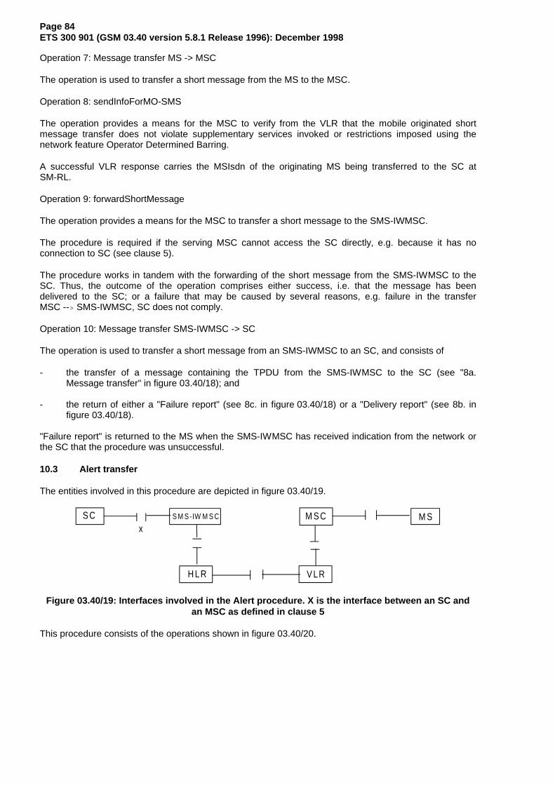
Page 84ETS 300 901 (GSM 03.40 version 5.8.1 Release 1996): December 1998
Operation 7: Message transfer MS -> MSC
The operation is used to transfer a short message from the MS to the MSC.
Operation 8: sendInfoForMO-SMS
The operation provides a means for the MSC to verify from the VLR that the mobile originated shortmessage transfer does not violate supplementary services invoked or restrictions imposed using thenetwork feature Operator Determined Barring.
A successful VLR response carries the MSIsdn of the originating MS being transferred to the SC atSM-RL.
Operation 9: forwardShortMessage
The operation provides a means for the MSC to transfer a short message to the SMS-IWMSC.
The procedure is required if the serving MSC cannot access the SC directly, e.g. because it has noconnection to SC (see clause 5).
The procedure works in tandem with the forwarding of the short message from the SMS-IWMSC to theSC. Thus, the outcome of the operation comprises either success, i.e. that the message has beendelivered to the SC; or a failure that may be caused by several reasons, e.g. failure in the transferMSC --> SMS-IWMSC, SC does not comply.
Operation 10: Message transfer SMS-IWMSC -> SC
The operation is used to transfer a short message from an SMS-IWMSC to an SC, and consists of
- the transfer of a message containing the TPDU from the SMS-IWMSC to the SC (see "8a.Message transfer" in figure 03.40/18); and
- the return of either a "Failure report" (see 8c. in figure 03.40/18) or a "Delivery report" (see 8b. infigure 03.40/18).
"Failure report" is returned to the MS when the SMS-IWMSC has received indication from the network orthe SC that the procedure was unsuccessful.
10.3 Alert transfer
The entities involved in this procedure are depicted in figure 03.40/19.
S C S M S -IW M S C M S C M Sx
V LRH LR
Figure 03.40/19: Interfaces involved in the Alert procedure. X is the interface between an SC andan MSC as defined in clause 5
This procedure consists of the operations shown in figure 03.40/20.

Page 85ETS 300 901 (GSM 03.40 version 5.8.1 Release 1996): December 1998
Three cases are distinguished:
- The MS becomes reachable when the MNRF is set but the MCEF is not set (figure 03.40/20a);- The MS becomes reachable when both the MNRF and the MCEF are set (figure 03.40/20b);- The MS notifies the network that it has memory available to receive one or more short messages
when the MCEF is set (figure 03.40/20c).
The operations between MSC and VLR, between HLR and VLR and between HLR and SMS-IWMSC arespecified in GSM 09.02. The operation between MS and MSC is specified in GSM 04.11. References tospecifications of other operations are given in clause 4.
SC SMS-IWMSC HLR MSC VLR MS
11. noteMsPresent <−−−−−−−−−−−−−−−−−−−−−−−−−−−−−−−−−−− 12. alertService- <−−−−−−−−−−−−−−−−− Centre 13. alertService- <−−−−−−−−−−−−−−−− Centre
−−−−−−−−−> : Operation invocation or message transfer
Figure 03.40/20a: The alert procedure when the MS becomes reachable,MNRF is set and MCEF is not set
SC SMS-IWMSC HLR MSC VLR MS
11. noteMsPresent <−−−−−−−−−−−−−−−−−−−−−−−−−−−−−−−−−−
−−−−−−−−−> : Operation invocation or message transfer
Figure 03.40/20b: The alert procedure when the MS becomes reachable,MNRF is set and MCEF is set

Page 86ETS 300 901 (GSM 03.40 version 5.8.1 Release 1996): December 1998
SC SMS-IWMSC HLR MSC VLR MS
14. smMemoryCapacityAvailable 1) <−−−−−−−−−−−−−−−−−−−−−−−−−−−−−−−−−−−−−−−−−−−−−−−−−−−−> 12. alertService- <−−−−−−−−−−−−−−−−− Centre 13. alertService- <−−−−−−−−−−−−−−−− Centre
−−−−−−−−−> : Operation invocation or message transfer<−−−−−−−−−> : Successful operation invocation or message transfer including report
References:1) : Described in GSM 04.11 and GSM 09.02
Figure 03.40/20c; The alert procedure when the MS notifies the network that it hasmemory available to receive one or more short messages and MCEF is set

Page 87ETS 300 901 (GSM 03.40 version 5.8.1 Release 1996): December 1998
Operation 11: noteMsPresent
The operation provides a means to transfer alert information from VLR to HLR.
The procedure is activated when the VLR detects that the MS is active, i.e. when the MS responds to apaging request.
Operation 12: alertServiceCentre
The operation provides a means to transfer alert information from HLR to MSC.
Operation 13: alertServiceCentre
The operation provides a means to transfer alert information from an SMS-IWMSC to an SC.
The operation consists of transfer of a message ("RP-ALERT-SC") from the SMS-IWMSC to the SC.
Operation 14: smMemoryCapacityAvailable
The operation provides a means for the MS to notify the network that it has memory available to receiveone or more short messages.
The following applies if the memory capacity available notification flag is implemented in the SIM.
The operation consists of transfer of a message ("RP-SM-MEMORY-AVAILABLE") from the MS to theHLR, and the return of an acknowledgement to the MS. When the MS rejects a short message due to lackof available memory capacity the need to transfer notification shall be stored in the SIM. After a attempt totransfer the RP-SM-Memory-Available message the following applies:
If the MS receives a positive acknowledgement it will unset the memory capacity exceeded notificationflag in the SIM and exit this procedure.
If the MS receives a negative acknowledgement indicating a permanent failure condition (as specified inGSM 04.11) it will unset the memory capacity exceeded notification flag in the SIM and exit the procedure.
If the MS receives a negative acknowledgement indicating a temporary failure condition (as specified inGSM 04.11) or receives no acknowledgement or an indication of failure by lower layers, it will repeat theattempt to transfer the message in accordance with procedures defined in GSM 04.11. If these repeatprocedures fail, the mobile will unset the memory capacity exceeded notification flag in the SIM and exitthis procedure.
If memory capacity has become available because memory is cleared, the value of the memory capacityexceeded notification flag is read. If the flag is set, the MS notifies the network that memory capacity isnow available as described above.
When the mobile is powered up or the SIM is inserted, the mobile shall check the memory capacityexceeded notification flag in the SIM; if the flag is set and the SIM has memory available to receive a shortmessage the mobile shall attempt to notify the network that it has memory available, as described above.

Page 88ETS 300 901 (GSM 03.40 version 5.8.1 Release 1996): December 1998
11 Mapping of error causes between RP layers
This clause describes the interworking between the relay layers on the radio interface (i.e. between theservicing MSC and the mobile station), and within the network (IE. between servicing MSC, and VLR,HLR, or GMSC).
11.1 Mobile Terminated short message transfer
If errors are indicated by the VLR after invocation of the "sendInfoFor-MT-SMS" operation, the appropriateerror information is returned to the SMS-GMSC in a failure report as specified in GSM 09.02 (negativeoutcome of "forwardShortMessage" see clause 10),
If errors are detected by the MSC during the transfer on the radio interface, the error cause returned in thereturn error of the MAP procedure ForwardShortMessage shall be set as follows:
Failure at the MSC Return error to be included in the MAP-procRP-ERROR message with error cause:
22 Memory capacity exceeded SM_DeliveryFailure withcause "MemoryCapacityExceeded"1)
Other error causes SM_DeliveryFailure withcause "equipmentProtocolError"1)
CP or lower layer error SM_DeliveryFailure with(e.g. RR, layer 2 failure)2) cause "equipmentProtocolError"1)
Mobile has no SM capability SM_DeliveryFailure withcause "equipmentNotSM-Equiped"1)0
TR1N timeout 2) SM_DeliveryFailure withMNSMS-error-ind (No SAPI 3) cause "equipmentProtocolError"1)
1) For definition of MAP error SM_DeliveryFailure and its parameter "cause" see GSM 09.02.2) The error causes of the RP-ERROR message, the CP layer and timer TR1N are defined in
GSM 04.11.
11.2 Memory available notification
If errors are indicated by the HLR (via the VLR) after invocation of the "ReadyForSM" operation, the MSCshall return the appropriate error information to the MS in a failure report (i.e. a RP-ERROR message)containing the following error cause:
Return error from ReadyForSM Cause value in the RP-ERROR message(Alert Reason is "memory available")DataMissing 38 Network out of orderUnexpectedDataValue 38 Network out of orderUnknownSubscriber 30 Unknown SubscriberFacilityNotSupported 69 Requested facility not implementedSystem Failure 38 Network out of order
NOTE: The coding and the use of the RP-ERROR message is specified in GSM 04.11.

Page 89ETS 300 901 (GSM 03.40 version 5.8.1 Release 1996): December 1998
11.3 Mobile Originated short message transfer
If errors are indicated by the VLR after invocation of the "sendInfoForMO-SMS" operation.(see clause 10),the MSC shall return the appropriate error information to the MS in a failure report (i.e. a RP-ERRORmessage) containing the following error cause:
Return error from SendInfoForMO-SMS Cause value in the RP-ERROR messageDataMissing 38 Network out of orderUnexpectedDataValue 38 Network out of orderTeleserviceNotProvisioned 50 Requested facility not subscribed
CallBarred - barringServiceActive 10 Call barred - operatorBarring 8 Operator determined barring
NOTE: The coding and the use of the RP-ERROR message is specified in GSM 04.11.
If errors are indicated by the SMS-IWMSC (negative outcome of the "forwardShortMessage),) the MSCshall send a failure report (i.e. a RP-ERROR message) to the MS, with the error cause coded as follows:
Return error from ForwardShortMessage Cause value in the RP-ERROR messageDataMissing 38 Network out of orderFacilityNotSupported 69 Requested facility not implemented
UnexpectedDataValue 38 Network out of order
SM-DeliveryFailure 1 Unassigned numbercause: unknownSC
SM-DeliveryFailure 42 Congestioncause: SC-Congestion
SM-DeliveryFailure 21 Short message transfer rejectedcause: invalidSME-Addr
SM-DeliveryFailure 28 Unidentified subscribercause: subscriberNotSC-Subscriber
Local or lower layer failure 38 Network out of order(e.g. reject condition,timer expired or transaction abort)
NOTE: The coding and the use of the RP-ERROR message is specified in GSM 04.11.

Page 90ETS 300 901 (GSM 03.40 version 5.8.1 Release 1996): December 1998
Annex A (informative): Protocol stacks for interconnecting SCs and MSCs
No mandatory protocol between the Service Centre (SC) and the Mobile Switching Centre (MSC) belowthe transfer layer is specified by GSM; this is a matter of agreement between SC and PLMN operators.
Some example protocols are provided in GSM 03.47 to assist SC and PLMN operators. These are basedon the following principles, which SC and PLMN operators are recommended to follow even if they choosenot to use one of the examples given in GSM 03.47:
The protocol(s) between SC and MSC below transfer layer should:
a) provide the service defined for SM-RL (see Subclause 9.3);
b) be based on widely accepted telecommunications protocols in the public domain;
c) permit open interconnection.

Page 91ETS 300 901 (GSM 03.40 version 5.8.1 Release 1996): December 1998
Annex B (informative): Information now contained in GSM 03.38
Annex B held information that is now contained in GSM 03.38.

Page 92ETS 300 901 (GSM 03.40 version 5.8.1 Release 1996): December 1998
Annex C (informative): Short message information flow
The diagrams in this annex describe the flow of primitives and parameters during the short messagetransfer. These diagrams refer to specifications GSM 03.40, 04.11 and 09.02. The parameters in dottedlines are optional. The abbreviations used in diagrams are listed below. The relevant specifications aregiven in parentheses. (*) stands for a common GSM abbreviations and (-) for a general abbreviation.
CM Call Management (*)CS CauSe (-)DA Destination Address (-)DCS Data Coding Scheme (03.40)DI Dialogue Identifier TCAPGMSCA Gateway MSC AddressHLR Home Location Register (*)IMSI International Mobile Subscriber Identity (*)MAL MSIsdn-Alert (03.40)MMS More Messages to Send (03.40)MR Message Reference (03.40)MS Mobile Station (*)MSC Mobile services Switching Centre (*)MSCA MSC AddressMSI Mobile waiting Set Indication (03.40)MSIsdn Mobile Station ISDN number (*)MSM More Short Messages (09.02)MSRN Mobile Station Roaming Number (*)MT Message Type (04.11)MTI Message Type Indicator (04.11)MWS Message Waiting Set (03.40)OA Originating Address (-)OC Operation Code (09.02)PCI Protocol Control Information (-)PDI Protocol DIscriminator (*)PRI PRIority (03.40)RCT ReCeption Time (03.40)REA REcipient Address (03.40)RL ReLay function (04.11)RP Reply Path (03.40)SC Service Centre (03.40)SCA Service Centre Address (03.40)SCTS Service Centre Time Stamp (03.40)SM Short Message (03.40)SM-AL Short Message Application Layer (03.40)SME Short Message Entity (03.40)SMI Short Message Identifier (03.40)SM-RL Short Message Relay Layer (03.40, 04.11)SMS-GMSC Short Message Service Gateway MSC (03.40)SMS-IWMSC Short Message Service Interworking MSC (03.40)SoR Status of Report (03.40)SM-TL Short Message Transfer Layer (03.40)SRI Status Report Indication (03.40)SRR Status Report Request (03.40)ST STatus (03.40)TCAP Transaction Capabilities Application Part (-)TID Transaction Identifier (*)UD User Data (-)UDL User Data Length (03.40)VLR Visitor Location Register (*)VP Validity Period (03.40)VPF Validity Period Format (03.40)

Page 93ETS 300 901 (GSM 03.40 version 5.8.1 Release 1996): December 1998
D C S
S E R V IC E C E N T R E
SMI D A O A PID S M
O A PID D C S S C T SM M S U D LMTI U D
SMI D A O A
PRI O AD A U D
S C A
U D
SM TL
S M R L
S M S - D E L I V E R
M S I S D N S C
PRI
PRI
S M E
R S - M T - D A T A . R E Q
T O T H E S M S - G M S C
SM AL
SMI
S R I
R P S R I
R P
M M S
M M S R P-M T -D A T A
T S -D E LIV E R .R E Q
NOTE: SMI is not carried via SM-RL of subclause 9.3.5 but is carried via the relay service between the SC and GMSC (see subclause 9.3.4.1).
Figure 1.1: Mobile terminated short message

Page 94ETS 300 901 (GSM 03.40 version 5.8.1 Release 1996): December 1998
SM RL
H L R
PRI
D A O A U DPRI O AD A
D A T C A P
M S I S D N
S M S - G M S C
O C MSISDN S C A
O C
F O R W A R D S H O R TMESSAGE (09 .02)
U D
TO THE MSC
SEND ROUTING INFO FOR SHORTMESSAGE (09 .02 )
S C A
S C A D A SMI DI
RP-MT-DATA
S C A
G M S C A DI
M S C A
SMI
F R O M S C
S H O R T M E S S A G E R O U T I N GINFORMATION MESSAGE (09 .02 )
M SMM M S UD
NOTE: A sequence of short messages will have MMS set to 1 in each RP-MT-DATA except the last (last will have MMS set to 0). Each RP-MT-DATA will be carried viaFORWARD SHORT MESSAGE via TCAP and will be assigned the same Dialogue Identifier as previous RP-MT-DATAS in the sequence.
Figure 1.2: Mobile terminated short message

Page 95ETS 300 901 (GSM 03.40 version 5.8.1 Release 1996): December 1998
O A PID D C S S C T SM M S U D LMTI U D
D A O A U D
S M S - D E L I V E R
MTI M R O A U D R P - D A T AU D L
R L
(04.11)
TO THE MS
S M E
+
SEND INFO FOR I /CCALL SET UP (09.02)
O C
(04.11)
M S C
MNSMS-EST-REQ (04 .11)
SM-RL-DATA-REQUEST
D A T C A PU DG M S C A DI
DI M R
F R O M G M S C
S C A
R P S R I
F O R W A R D S H O R TM E S S A G E (09.02)M S M
NOTE: MR is of local significance to the MSC/MS interface and is not the value supplied to the MSC
Figure 1.3: Mobile terminated short message

Page 96ETS 300 901 (GSM 03.40 version 5.8.1 Release 1996): December 1998
MTI M R O A
SMI O A U D
O A PID D C S S C T S U D L U D
D C SSMI O A PID M M S S MS C A
S M S - D E L I V E R
MOBILE STATION
S M - A L
SM-TL
SM-RL
C M
S CS M E
S C T S
R P - D A T APRI
(04.11)
TS-DELIVER. IND
(04.11)
MNSMS-EST- IND (04.11)
FROM THE MSC
SM-RL-DATA- IND (RS-MT-DATA. IND)
UDL + UD
S R I R P
MTI R P S R IM M S
Figure 1.4: Mobile terminated short message

Page 97ETS 300 901 (GSM 03.40 version 5.8.1 Release 1996): December 1998
S M - A L
SM-TL
SM-RL
MTI M RMTIM R
MOBILE STATION
C M
R P - A C K O R R P - E R R O R
C S
PDI TID M T U D
MNSMS-DATA-REQ (04 .11)
C P - D A T A(04.11)
R P - A C K(04.11)
RP-DATA (04.11)
RP-ERROR (04 .11)
TO THE MSC
U D
MTI F C S S M S -D E LIV E R -R E P O R T
Figure 2.1: Acknowledgement in the MT case

Page 98ETS 300 901 (GSM 03.40 version 5.8.1 Release 1996): December 1998
MTI M R M RMTI
M S C
SM-RL
R L
MTI M R M RMTI
R P - A C K O R R P - E R R O R
PDI TID M T U D
C S
C P - D A T A(04.11)
MNSMS-DATA- IND (04.11)
TO THE SMS-GMSC
SMRL-REPORT- IND(04.11)
RP-ERROR (04 .11)C SR P - A C K(04.11)
FROM THE MS
C M
M RDIDI DIU D U DT C A P
U D
U D
NOTE: The cause carried via UD of TCAP is not the cause supplied via RP-ERROR but is the cause resulting from application of the mapping specified by table 8.5 of04.11.
Figure 2.2: Acknowledgement in the MT case

Page 99ETS 300 901 (GSM 03.40 version 5.8.1 Release 1996): December 1998
S M S - G M S C
SMIR P - A C K
S M - R L
S C A D A SMI DI
DI U DT C A P
F R O M M S C
SMI C S M W S R P - E R R O R
R E S U L T
T O T H E S C
S E T M E S S A G E W A IT IN G D A T A (09 .02)
U DM A L
NOTE 1: The MAP operation "SetMessageWaitingData" is invoked only if a cause "Absent Subscriber" is carried in TCAP UD.
NOTE 2: The cause delivered to the SC is not necessarily the cause carried via TCAP but is one of the set specified by table 03.40/1.
Figure 2.3a: Acknowledgement in the MT case

Page 100ETS 300 901 (GSM 03.40 version 5.8.1 Release 1996): December 1998
SMI
R P - A C K SMI R P - E R R O R
S E R V I C E C E N T R E
SMI
SMI C SM W S
SMI M W S
SMI
S M - R L
F R O M S M S - G M S C
R S - R E P O R T
T S - R E P O R T
S M - T L
R S - E R R O R
T S - R E P O R TS o RS o R
C SM W S
U D
MTI F C S S M S -D E LIV E R -R E P O R T
U D
M A L
M A L
Figure 2.3b: Acknowledgement in the MT case

Page 101ETS 300 901 (GSM 03.40 version 5.8.1 Release 1996): December 1998
MOBILE STATION
D A PID D C S V P S M
M R D A PID D C S V P U D L U D
SMI D A U D
M R D A U D
S C
SMS-SUBMIT
SM-AL
SM-TL
SM-RL
C M
MTI
S C A
TO THE MSC
S M E
UDL +RP-DATA
(04.11)
S CRP-DATA
TS-SUBMIT .REQ
(04.11)
MNSMS-EST-REQ (04 .11)
RS-MO-DATA.REQ (SM-RL-DATA-REQ)
SMI S R I R P
MTI VPF R P S R I
NOTE: The mapping of SMI to MR by the MS is a local matter.
Figure 3.1: Mobile originated short message

Page 102ETS 300 901 (GSM 03.40 version 5.8.1 Release 1996): December 1998
M S C
MTI M R D A U DMNSMS-EST- IND
SM-RL
C MFROM THE MS
UDL +
O A U DD A
(04.11)
TO THE SMS- IWMSC
(RP-DATA)
SEND INFO FOR O/G CALL SET UP(09.02)
COMPLETE CALL (09 .02)
M S I S D N
V L R
F O R W A R DS H O R T M E S -SAGE (09.02)
O C
U D
M S I S D N
O A M R DI
S C A
O A G M S C A T C A PDI
M S C A
Figure 3.2: Mobile originated short message

Page 103ETS 300 901 (GSM 03.40 version 5.8.1 Release 1996): December 1998
SM-RL
FROM THE MSC
U D
S M S - I W M S C
TO THE SC
O A U D
O A
O A U D
M R DI
I W M S C A DI
M R
F O R W A R DS H O R T M E S S A G E(09.02)
M S I S D NS C A
O C
T C A P
TC-BEGIN
RP-DATA-MO
D A
NOTE: MR is of local significance to the IWMSC/SC interface and is not the value supplied by the MS via the MS/MSC interface
Figure 3.3: Mobile originated short message
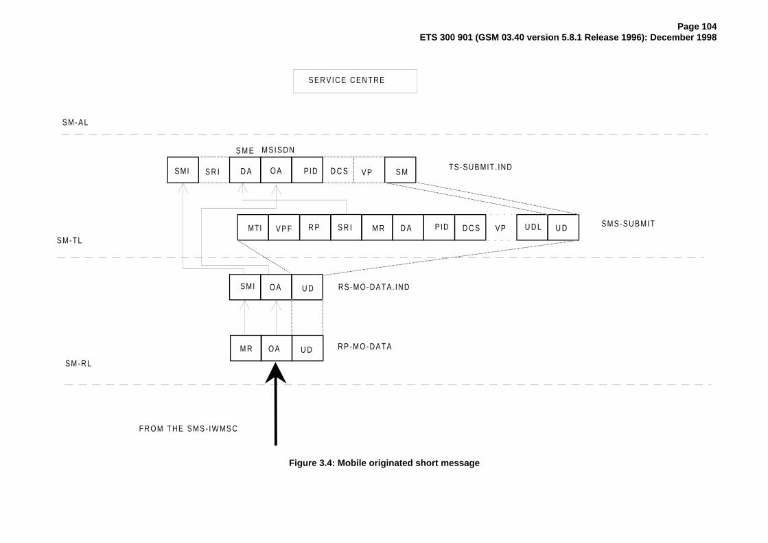
Page 104ETS 300 901 (GSM 03.40 version 5.8.1 Release 1996): December 1998
S E R V I C E C E N T R E
S M - A L
SM-TL
SM-RL
U D
SMI
MTI M R D A PID D C S VP U D L U D
D A O A PID D C S VP
M S I S D N
RP-MO-DATA
U D
S M
O A
O A
V P F
S M E
TS-SUBMIT. IND
RS-MO-DATA. IND
SMS-SUBMIT
FROM THE SMS- IWMSC
M R
SMI S R I
R P S R I
Figure 3.4: Mobile originated short message

Page 105ETS 300 901 (GSM 03.40 version 5.8.1 Release 1996): December 1998
S E R V I C E C E N T R E
M R M R C SR P - A C K R P - E R R O R
SM-RL
TO THE SMS- IWMSC
U D
MTI F C S S M S -S U B M IT -R E P O R T
Figure 4.1a: Acknowledgement in the MO case

Page 106ETS 300 901 (GSM 03.40 version 5.8.1 Release 1996): December 1998
M RR P - A C K R P - E R R O R
S M S - I W M S C
M R
M R C S
DI
FROM THE SC T O T H E M S C
T C A P T C A PDI DI U DU D
Figure 4.1b: Acknowledgement in the MO case
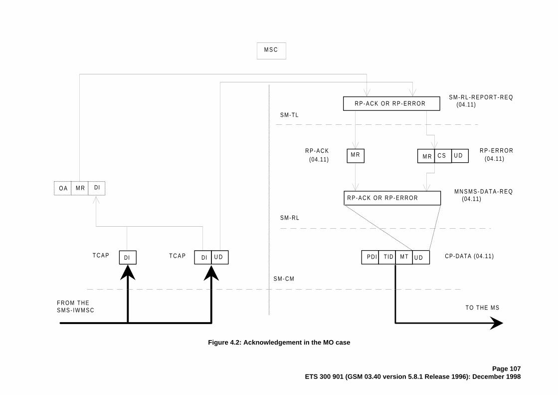
Page 107ETS 300 901 (GSM 03.40 version 5.8.1 Release 1996): December 1998
M S C
SM-RL
R P - A C K R P - E R R O R
R P - A C K O R R P - E R R O R
PDI TID M T U D CP-DATA (04.11)
M N S M S - D A T A - R E Q (04.11)
R P - A C K O R R P - E R R O R
M R M R C S(04.11) (04.11)
T C A P T C A PDI DI U D
FROM THES M S - I W M S C TO THE MS
O A M R DI
S M - C M
SM-TL
S M - R L - R E P O R T - R E Q (04.11)
U D
Figure 4.2: Acknowledgement in the MO case

Page 108ETS 300 901 (GSM 03.40 version 5.8.1 Release 1996): December 1998
MOBILE STATION
SM-RL
C M
SM-TL
R P - A C K R P - E R R O R
SMI
SMI S o R
SMI
SMI S o R
R P - A C K O R R P - E R R O R
C S
TS-REPORT. IND TS-REPORT. IND
MTI M R MTI M R
C S
MNSMS-DATA- IND (04.11)
CP-DATA (04 .11)
FROM THE MSC
SM-RL-REPORT- IND SM-RL-REPORT- INDU D
MTI F C S S M S -S U B M IT -R E P O R T
U D
Figure 4.3: Acknowledgement in the MO case

Page 109ETS 300 901 (GSM 03.40 version 5.8.1 Release 1996): December 1998
Annex D (informative): Mobile Station reply procedures
D.1 Introduction
The reply procedures specified in this annex should be followed by a mobile station when replying to ashort message, i.e. when generating a MO SM in response to a received MT SM, addressed to theoriginator of that MT SM. The main purpose of this annex is to specify how the MS selects the servicecentre for delivering that MO SM: an arbitrary SME may only be reached by submitting the reply SM to aspecific SC, known to be able of delivering to that SME.
D.2 The scope of applicability
The reply procedures in clauses 5 and 6 of this annex should be followed by every MS which fulfils thefollowing criteria:
1) The MS automatically selects the value for the RP-Destination-Address parameter inRP-MO-DATA, or the MS has the SC address within the SM-RL entity. (That is to say: the humanuser is not obliged to manually key in the SC address for every MO short message).
2) The MS or an application within it supports some form of replying to a MT SM with a MO SM. (Thatis to say: in the process of generating the reply MO SM, any reference whatsoever, implicit orexplicit, is made to the original MT SM.).
3) The replying support of (2) is to be equally available towards every SME.
When an SME submits an SM to an SC for delivery, it may request that the SC sets the TP-Reply-Pathparameter in the SM to be delivered. If the submitting SME is an MS, the reply path requesting procedure;in clause 4 of this annex may be applied. However, an SC may support the reply procedures withoutsupporting the reply path requesting procedure; in that case, the SC sets the TP-Reply-Path parameter onanother basis, which must be the case if the SM originates from an SME which is not an MS.
D.3 Terminology
An originating SME submits an original SM to an original SC, which delivers the original MT SM to areplying MS. The replying MS sends back a reply MO SM, a MO SM which is generated (automatically orby human operations) in response to the original MT SM, and which is addressed to the originating SME.
If the originating SME is an MS, the original MT SM is submitted within an SMS-SUBMIT PDU; we say thatreply path is requested if the TP-Reply-Path parameter is set in the SMS-SUBMIT PDU of the original MTSM.
We say that reply path exists if the TP-Reply-Path parameter was set in the SMS-DELIVER PDU of theoriginal MT SM; we say that reply path does not exist otherwise.
The replying MS may have a default SC which is normally used for delivering all the MO short messagesoriginated from the replying MS. Alternatively, a human user or automatic application may specify aselected SC for delivering a particular SM (thus the term selected SC refers to an SC address selected forone short message only).
D.4 The reply path requesting procedure
The discussion in this clause applies to cases when the originating SME is a mobile station only. The replyprocedures discussed in the sections to follow this one are independent of the type of the originating SME.
The reply path is requested by the originating SME (an MS) by setting the TP-Reply-Path parameter in theSMS SUBMIT PDU of the original SM. If the original SC supports reply path requesting for the originatingSME (an MS), it will take notice of the TP-Reply-Path parameter in the SMS-SUBMIT PDU and set theTP-Reply-Path parameter in the SMS-DELIVER PDU of the original MT SM towards the replying MS.Hence, reply path exists for the replying MS towards the originating SME (an MS).

Page 110ETS 300 901 (GSM 03.40 version 5.8.1 Release 1996): December 1998
D.5 The reception of an original MT SM
When a replying MS receives an original MT SM, it then has
1) originating SME = TP-Originating-Address in the SMS-DELIVER PDU,
2) original SC = RP-Originating-Address in RPS-MT-DATA, and
3) reply path exists / reply path does not exist = TP-Reply-Path in SMS-DELIVER PDU (set / not set).
D.6 The submission of the reply MO SM
According to clause 5, the replying MS knows if
a) reply path exists orb) reply path does not exist.
We then specify that when submitting the reply MO SM, the replying MS should use parameters asfollows:
1) TP-Destination-Address in SMS-SUBMIT PDU = originating SME,
2a) If reply path exists:RP-Destination-Address in RP-MO-DATA = original SC,
2b) If reply path does not exist:RP-Destination-Address in RS-MO-DATA = selected SC or default SC or original SC,
3a) If reply path exists:after submitting one reply MO SM, the reply path does not exist any more.
In case (2b), it is allowed to use the original SC or the default SC, but then there is no guarantee that theoriginal/default SC will deliver the reply MO SM. (The original SC may refuse to deliver, if the replying MSis not its subscriber; the default SC may be unable to deliver, if it has no access path to the originatingSME.)
Requirement (3a) states that the case (a), reply path exists, holds for one reply MO SM only (per originalMT SM).
D.7 Usage of SCs for replying
The specification in this annex supports the following way of replying.
The original MT SM and the reply MO SM are delivered by the same SC, the original SC. This principlemaximizes the probability that the SC can e.g. route the reply MO SM to the proper data network forreaching the originating SME; this principle is a must, if the originating SME is integrated within the originalSC.
If the original SC by any means whatsoever knows that it is both willing and able to deliver one (potential)reply MO SM, it may indicate this fact by setting the TP-Reply-Path parameter in the original MT SM. Theoriginal SC thus commits itself to delivering one reply MO SM; let us call this reply delivery commitment.
One reason for the SC to make the reply delivery commitment may be the reply path requesting procedurespecified in clause 4 on this annex.
The reply path commitment is not valid forever, but the original SC pay have e.g. a time limit formaintaining this commitment.

Page 111ETS 300 901 (GSM 03.40 version 5.8.1 Release 1996): December 1998
D.8 Replying possibilities for Phase 1 mobile stations
The Phase 2 mobile stations should support the procedures in this annex (if they fulfil the criteria inclause 2 of it). Yet, Phase 1 mobile stations, too, may apply steps (1) and (2a) in clause 6 of this annex,i.e. reply via the original SC, automatically or manually (by choosing selected SC = original SC), despitethe fact that the TP-Reply-Path parameter will be ignored by them. The delivery of the reply MO SMcannot be guarantied in this case, yet the possibility of delivery may be improved (especially if theoriginating SME is not an MS.)
D.9 The resulting service for originating SMEs
As the consequence of the replying procedures specified in this annex, all SMEs and applications withinthem may assume that replying from all mobile stations is always possible, provided that the mobilestations do support the proper replying mechanism itself (human response in context with the original MTSM, automatic replying by an application, application level protocols, etc.).

Page 112ETS 300 901 (GSM 03.40 version 5.8.1 Release 1996): December 1998
Annex E (informative): Change History
SMG# TDoc SPEC VERS CR REV
PHASE
CAT
SUBJECT NEW_VERS
S17 068/96 03.40 A021 1 2+ D TP-MR values on receipt of RP-error 5.1.0S17 068/96 03.40 A022 1 2+ D Bit order of TP-CT 5.1.0S17 068/96 03.40 A023 1 2+ D TP-RP incorrect definition 5.1.0S17 068/96 03.40 A024 1 2+ D Bit order convention 5.1.0S17 068/96 03.40 A025 1 2+ D TP-UDL value when TP-UD header is present 5.1.0S17 068/96 03.40 A026 1 2+ D TP element vlues in concatenated SMs 5.1.0S17 068/96 03.40 A027 2 2+ B User Data Header IEI values 5.1.0S17 073/96 03.40 A028 1 2+ B Universal Character Coding Scheme (UCS2), international
Alphabet5.1.0
S17 068/96 03.40 A029 1 2+ D Clarification of the use of TP-MMS 5.1.0S18 242/96 03.40 5.1.0 A002 2+ B SIM Data download 5.2.0S18 242/96 03.40 5.1.0 A031 2+ C Support of UCS2 for SMS 5.2.0S18 242/96 03.40 5.1.0 A032 2+ D Updated information flow diagram 5.2.0S18 242/96 03.40 5.1.0 A033 2+ F User data length 5.2.0S18 242/96 03.40 5.1.0 A035 2+ F MSISDN -Alert in RP error 5.2.0S18 242/96 03.40 5.1.0 A038 2+ A TP - User data header padding (phase 2+) 5.2.0S18 242/96 03.40 5.1.0 A039 2+ B Service Centre Time Stamp 5.2.0S19 394/96 03.40 5.2.0 A041 2+ B RP-Ack PDU 5.3.0S19 394/96 03.40 5.2.0 A042 2+ D Transfering SM between PLMNs 5.3.0S20 608/96 03.40 5.3.0 A043 2+ D Ambiguity in section 9.2.3.1 5.4.0S20 608/96 03.40 5.3.0 A044 2+ D Improper presentation of TP-DCS in section 9.2.2.2 5.4.0S20 607/96 03.40 5.3.0 A045 2+ B Over the air depersonalisation of the ME 5.4.0S20 608/96 03.40 5.3.0 A046 2+ F RP user data is an optional parameter in RP Error in the MSC-
MS case5.4.0
S20 607/96 03.40 5.3.0 A047 2+ B SMS - Internet Email interworking 5.4.0S20 608/96 03.40 5.3.0 A048 2+ D Table entries missing in section 9.2.2.3 5.4.0S20 607/96 03.40 5.3.0 A049 2+ C Fix upward compatibility 5.4.0S20 608/96 03.40 5.3.0 A050 2+ D Corrections to several editorial errors in tables 5.4.0s21 054/97 03.40 5.4.0 A011 4 2+ B Absent Subscriber diagnostic info and its storage in the HLR 5.5.0s21 180/97 03.40 5.4.0 A051 2+ B Application port addressing scheme 5.5.0s21 058/97 03.40 5.4.0 A052 2+ B SMS compression 5.5.0s22 413/97 03.40 5.5.0 A053 2+ F Concatenation of UCS2 5.6.0s22 413/97 03.40 5.5.0 A054 2+ B SIM application Toolkit, sent to SMG9 as LS 5.6.0s22 413/97 03.40 5.5.0 A055 R97 B SMS control characters 5.6.0s22 413/97 03.40 5.5.0 A056 2+ B SMS validity period 5.6.0s22 413/97 03.40 5.5.0 A057 R97 B Source Indicator in User Data Header 5.6.0s22 413/97 03.40 5.5.0 A058 R97 B Status report PDU Enhancements 5.6.0s22 413/97 03.40 5.5.0 A059 R97 B User Data Header 5.6.0s23 97-696 03.40 5.6.1 A061 R96 F Correction of numbers 5.7.0s26 98-291 03.40 5.7.0 A068 R96 F Queuing of MT SMS at the VMSC 5.8.0s26 98-291 03.40 5.7.0 A073 R96 F TP-User Data (TP-UD), SMSC Control Parameters 5.8.0
5.8.0 Version update for publication 5.8.1

Page 113ETS 300 901 (GSM 03.40 version 5.8.1 Release 1996): December 1998
History
Document history
December 1995 Publication of Version 5.0.0
March 1996 Publication of Version 5.1.0
May 1996 Publication of Version 5.2.0
July 1996 Publication of Version 5.3.0
November 1996 Unified Approval Procedure UAP 58: 1996-11-18 to 1997-03-14
April 1997 First Edition
May 1997 One-step Approval Procedure OAP 9735: 1997-05-02 to 1997-08-29(Second Edition)
August 1997 One-step Approval Procedure OAP 9752: 1997-08-29 to 1997-12-26(Third Edition)
January 1998 Third Edition
May 1998 One-step Approval Procedure OAP 9841: 1998-05-20 to 1998-10-16(Fourth Edition)
August 1998 One-step Approval Procedure OAP 9850: 1998-08-14 to 1998-12-11(Fifth Edition)
December 1998 Fifth Edition
ISBN 2-7437-2745-4Dépôt légal : Décembre 1998