Embed Size (px)
Citation preview
1
EUROPEAN FRICTION STIR WELDING SPECIALIST (EFSW-S) AND
ENGINEER (EFSW-E)
This project has been funded with support from the European Commission. This publication reflects the views only of the author, and the Commission cannot be held responsible for any use which may be made of the information contained therein - ERASMUS + KA2: 2017-1-SK01-KA202-035415 2
7. Quality
Scope:7.1 Destructive testing
7.2 Standards for destructive testing and acceptance criteria
7.3 Non-destructive testing (NDT)
7.4 Standards for non-destructive testing and acceptance criteria
7.5 Equipment calibration and reproducibility
EFSW-S, EFSW-E

7.1 Destructive testing
Destrictive testing of welded joints in FSW is connected with the qualification of welding procedures (WPQR). Because the majority of the commercial applications of FSW involve aluminium and aluminium alloys, existing standards deals only with this metal: ISO 25239-4:2011 Friction stir welding – Aluminium – Specification and qualification of welding procedures AWS D17.3/D17.3M:2016 Specification for Friction Stir Welding of Aluminum Alloys for Aerospace Applications
These two standards cover both butt and lap weld joints. Butt weld joints represent more than 85 % of all welds, produced by FSW process.
This project has been funded with support from the European Commission. This publication reflects the views only of the author, and the Commission cannot be held responsible for any use which may be made of the information contained therein - ERASMUS + KA2: 2017-1-SK01-KA202-035415 3
EFSW-S, EFSW-E
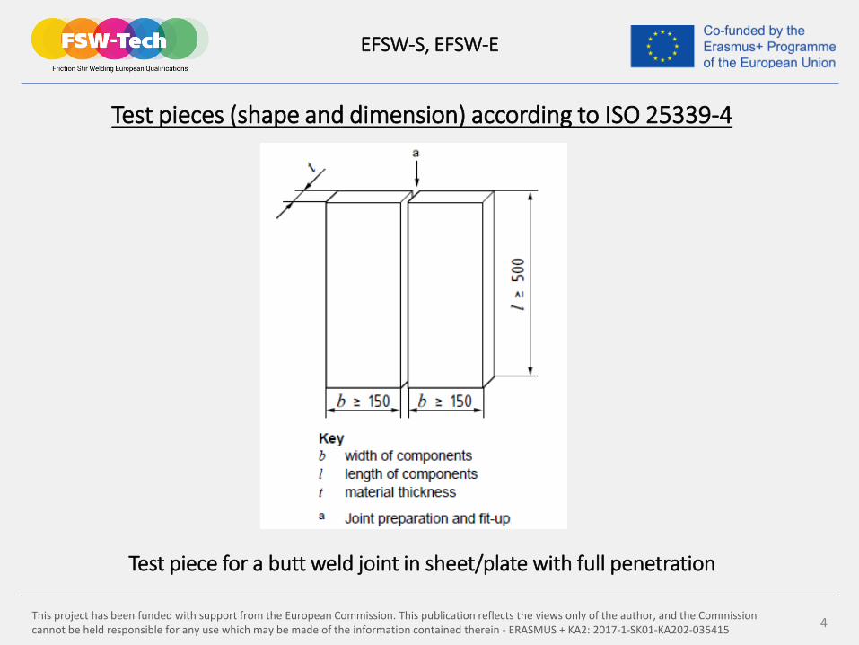
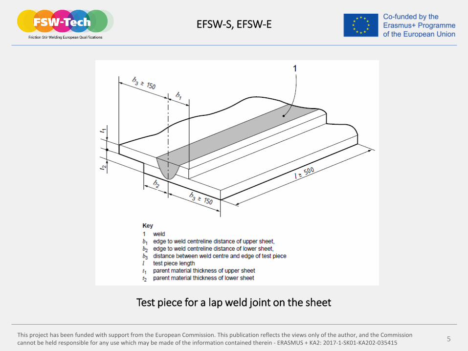
Test pieces (shape and dimension) according to ISO 25339-4
Test piece for a butt weld joint in sheet/plate with full penetration
This project has been funded with support from the European Commission. This publication reflects the views only of the author, and the Commission cannot be held responsible for any use which may be made of the information contained therein - ERASMUS + KA2: 2017-1-SK01-KA202-035415 4
EFSW-S, EFSW-E
This project has been funded with support from the European Commission. This publication reflects the views only of the author, and the Commission cannot be held responsible for any use which may be made of the information contained therein - ERASMUS + KA2: 2017-1-SK01-KA202-035415 5
EFSW-S, EFSW-E
Test piece for a lap weld joint on the sheet

This project has been funded with support from the European Commission. This publication reflects the views only of the author, and the Commission cannot be held responsible for any use which may be made of the information contained therein - ERASMUS + KA2: 2017-1-SK01-KA202-035415 6
Extent of destructive testings for butt weld joints in FSW
Special destructive tests in butt weld joints include: Fatigue testing Hardness and microhardness examinations
EFSW-S, EFSW-E
Type of testing ISO 25329-4 AWS D17.3
Transverse tensile test 2 specimens 4 specimens
Transverse bend test (wrought materials)
2 specimens (root)2 specimens (face) /
Fracture test (cast materials)
2 specimens (root)2 specimens (face) /
Macroscopic examination 1 specimen 2 specimens
Fracture toughness / if required
This project has been funded with support from the European Commission. This publication reflects the views only of the author, and the Commission cannot be held responsible for any use which may be made of the information contained therein - ERASMUS + KA2: 2017-1-SK01-KA202-035415 7
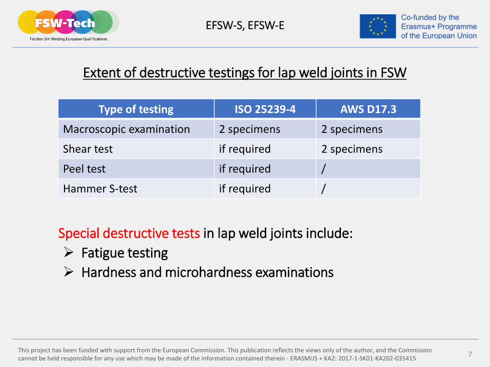
Extent of destructive testings for lap weld joints in FSW
Special destructive tests in lap weld joints include: Fatigue testing Hardness and microhardness examinations
EFSW-S, EFSW-E
Type of testing ISO 25239-4 AWS D17.3
Macroscopic examination 2 specimens 2 specimens
Shear test if required 2 specimens
Peel test if required /
Hammer S-test if required /
This project has been funded with support from the European Commission. This publication reflects the views only of the author, and the Commission cannot be held responsible for any use which may be made of the information contained therein - ERASMUS + KA2: 2017-1-SK01-KA202-035415 8
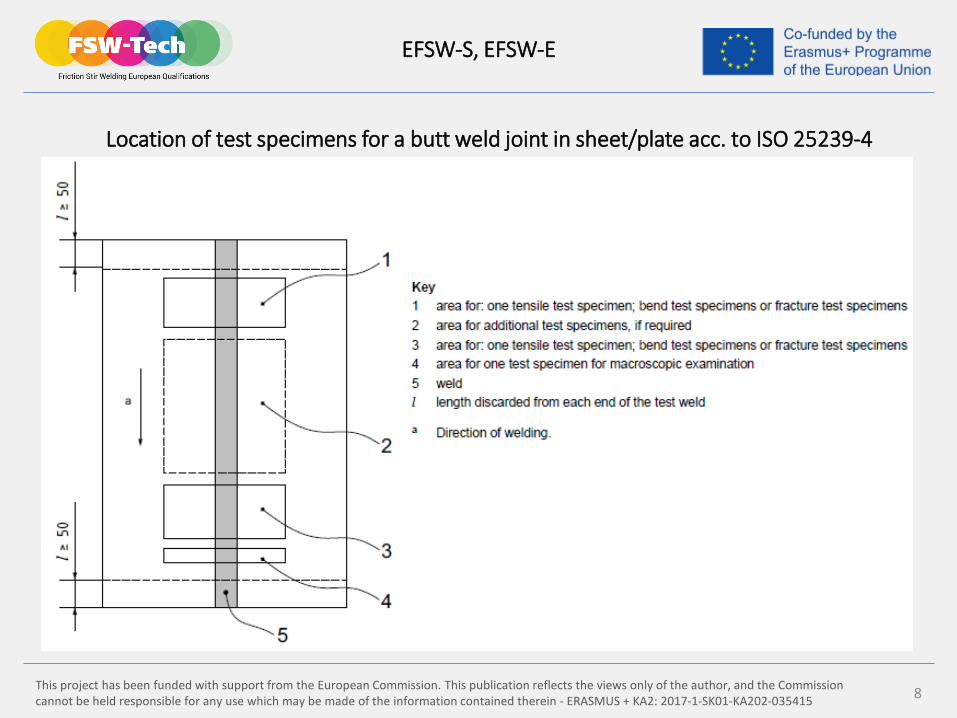
Location of test specimens for a butt weld joint in sheet/plate acc. to ISO 25239-4
EFSW-S, EFSW-E
This project has been funded with support from the European Commission. This publication reflects the views only of the author, and the Commission cannot be held responsible for any use which may be made of the information contained therein - ERASMUS + KA2: 2017-1-SK01-KA202-035415 9
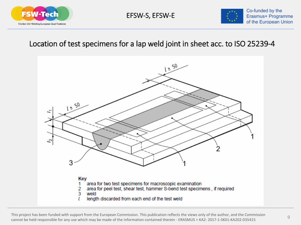
Location of test specimens for a lap weld joint in sheet acc. to ISO 25239-4
EFSW-S, EFSW-E
This project has been funded with support from the European Commission. This publication reflects the views only of the author, and the Commission cannot be held responsible for any use which may be made of the information contained therein - ERASMUS + KA2: 2017-1-SK01-KA202-035415 10
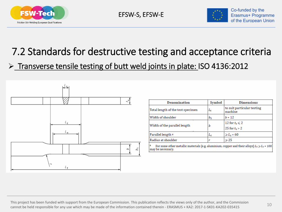
7.2 Standards for destructive testing and acceptance criteria Transverse tensile testing of butt weld joints in plate: ISO 4136:2012
EFSW-S, EFSW-E
This project has been funded with support from the European Commission. This publication reflects the views only of the author, and the Commission cannot be held responsible for any use which may be made of the information contained therein - ERASMUS + KA2: 2017-1-SK01-KA202-035415 11
EFSW-S, EFSW-E
This project has been funded with support from the European Commission. This publication reflects the views only of the author, and the Commission cannot be held responsible for any use which may be made of the information contained therein - ERASMUS + KA2: 2017-1-SK01-KA202-035415 12
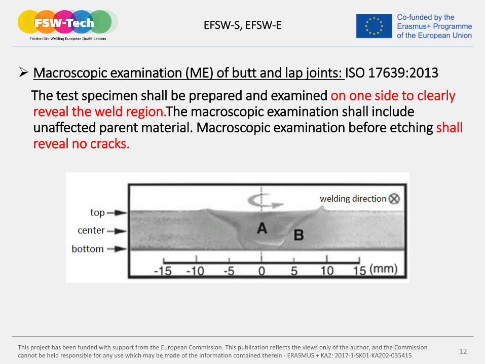
Macroscopic examination (ME) of butt and lap joints: ISO 17639:2013
The test specimen shall be prepared and examined on one side to clearlyreveal the weld region.The macroscopic examination shall include unaffected parent material. Macroscopic examination before etching shall reveal no cracks.
Macro examination of FSW butt weld on aluminium alloy AA6063-T5
EFSW-S, EFSW-E
This project has been funded with support from the European Commission. This publication reflects the views only of the author, and the Commission cannot be held responsible for any use which may be made of the information contained therein - ERASMUS + KA2: 2017-1-SK01-KA202-035415 13
Visual testing (VT) of butt and lap weld joints: ISO 17637:2016
This inspection is generally the first and simplest type of inspection. VT inspection on weld face and root shall be done in 100 % extenton finished FWS joints of the parts, welded with this proces.
For both tests (ME, VT), the acceptance levels of ISO 25239-5:2011,Annex A, shall apply. Other imperfections shall be within thespecified limits of the relevant requirements or the design specification.
EFSW-S, EFSW-E
This project has been funded with support from the European Commission. This publication reflects the views only of the author, and the Commission cannot be held responsible for any use which may be made of the information contained therein - ERASMUS + KA2: 2017-1-SK01-KA202-035415 14
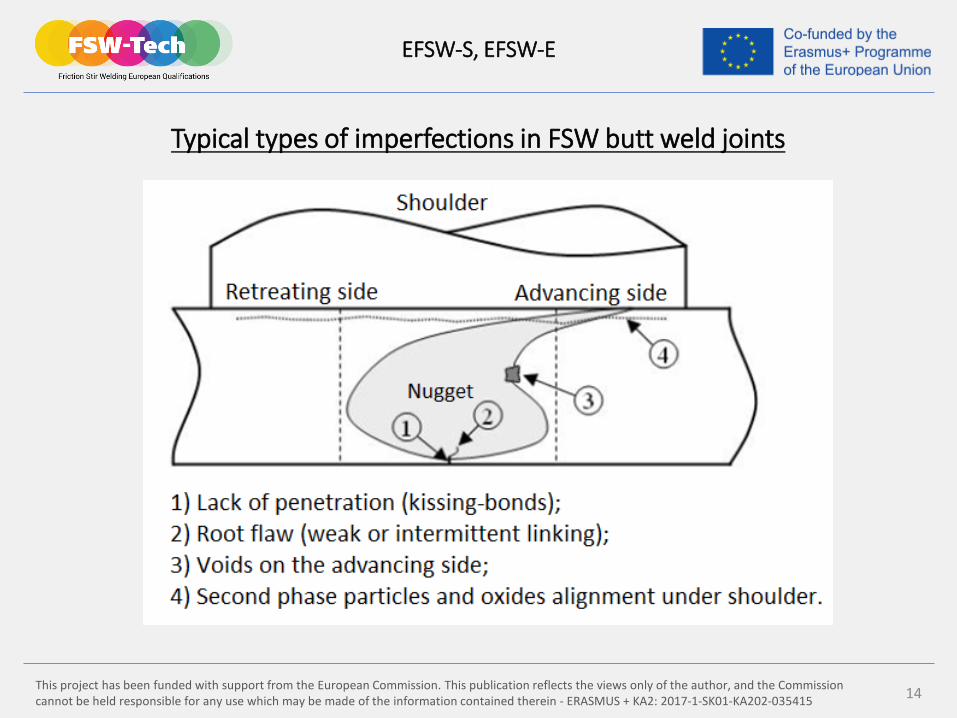
Typical types of imperfections in FSW butt weld joints
EFSW-S, EFSW-E
This project has been funded with support from the European Commission. This publication reflects the views only of the author, and the Commission cannot be held responsible for any use which may be made of the information contained therein - ERASMUS + KA2: 2017-1-SK01-KA202-035415 15
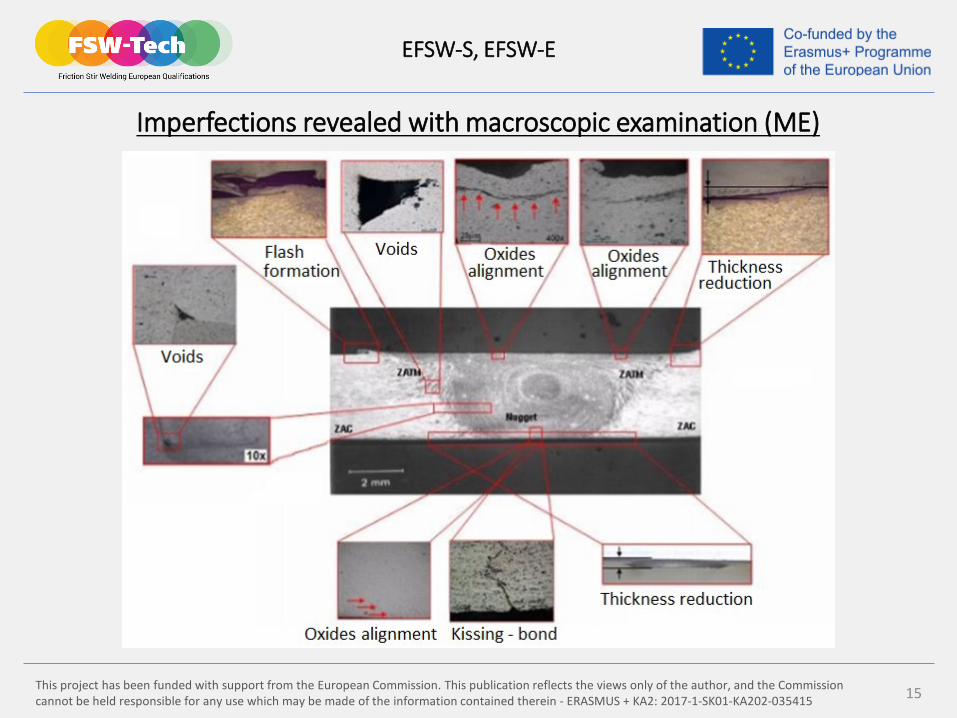
Imperfections revealed with macroscopic examination (ME)
EFSW-S, EFSW-E
This project has been funded with support from the European Commission. This publication reflects the views only of the author, and the Commission cannot be held responsible for any use which may be made of the information contained therein - ERASMUS + KA2: 2017-1-SK01-KA202-035415 16
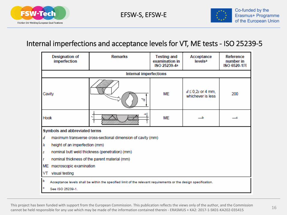
Internal imperfections and acceptance levels for VT, ME tests - ISO 25239-5
EFSW-S, EFSW-E
This project has been funded with support from the European Commission. This publication reflects the views only of the author, and the Commission cannot be held responsible for any use which may be made of the information contained therein - ERASMUS + KA2: 2017-1-SK01-KA202-035415 17
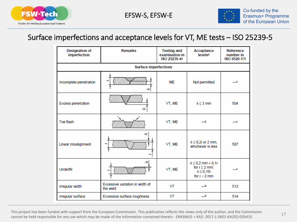
Surface imperfections and acceptance levels for VT, ME tests – ISO 25239-5
EFSW-S, EFSW-E
This project has been funded with support from the European Commission. This publication reflects the views only of the author, and the Commission cannot be held responsible for any use which may be made of the information contained therein - ERASMUS + KA2: 2017-1-SK01-KA202-035415 18
7.3 Non-destructive testing (NDT)
The NDT methods used to inspect FSW weld joints are fundamentallythe same as those used for other types of welds.
Mandatory NDT methods:
Liquid penetrant testing (PT)
Radiographic testing (RT)
Ultrasonic testing (UT)
Special NDT methods:
Eddy-current testing (ET)
EFSW-S, EFSW-E

This project has been funded with support from the European Commission. This publication reflects the views only of the author, and the Commission cannot be held responsible for any use which may be made of the information contained therein - ERASMUS + KA2: 2017-1-SK01-KA202-035415 19
Liquid penetrant testing (PT):
This is widely applied and low-cost inspection method used to locate surface breaking imperfections in all non-porous materials (metals, plastics, ceramics). PT is based upon the capillary action, where low surface tension fluid (dye) penetrates into clean and dry surface-breaking discontinuities.
EFSW-S, EFSW-E
This project has been funded with support from the European Commission. This publication reflects the views only of the author, and the Commission cannot be held responsible for any use which may be made of the information contained therein - ERASMUS + KA2: 2017-1-SK01-KA202-035415 20
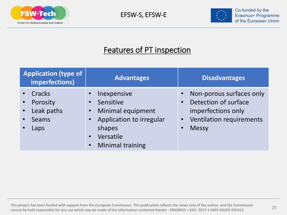
Features of PT inspection
EFSW-S, EFSW-E
Application (type ofimperfections) Advantages Disadvantages
• Cracks• Porosity• Leak paths• Seams• Laps
• Inexpensive• Sensitive• Minimal equipment• Application to irregular
shapes• Versatile• Minimal training
• Non-porous surfaces only• Detection of surface
imperfections only• Ventilation requirements• Messy
This project has been funded with support from the European Commission. This publication reflects the views only of the author, and the Commission cannot be held responsible for any use which may be made of the information contained therein - ERASMUS + KA2: 2017-1-SK01-KA202-035415 21
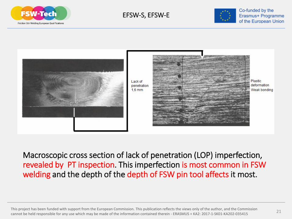
Macroscopic cross section of lack of penetration (LOP) imperfection, revealed by PT inspection. This imperfection is most common in FSW welding and the depth of the depth of FSW pin tool affects it most.
EFSW-S, EFSW-E
This project has been funded with support from the European Commission. This publication reflects the views only of the author, and the Commission cannot be held responsible for any use which may be made of the information contained therein - ERASMUS + KA2: 2017-1-SK01-KA202-035415 22
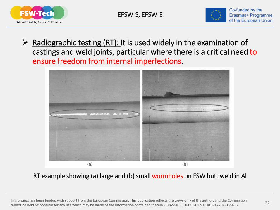
Radiographic testing (RT): It is used widely in the examination of castings and weld joints, particular where there is a critical need to ensure freedom from internal imperfections.
RT example showing (a) large and (b) small wormholes on FSW butt weld in Al
EFSW-S, EFSW-E

This project has been funded with support from the European Commission. This publication reflects the views only of the author, and the Commission cannot be held responsible for any use which may be made of the information contained therein - ERASMUS + KA2: 2017-1-SK01-KA202-035415 23
Some typical radiographs for FSW weld joints in Al-alloys
EFSW-S, EFSW-E
weld photo radiograph imperfections
Lack of penetration,wormhole
Lack of penetration, crack, voids
Lack of penetration, crack, incomplete fusion
Lack of penetration, crack, incomplete fusion
This project has been funded with support from the European Commission. This publication reflects the views only of the author, and the Commission cannot be held responsible for any use which may be made of the information contained therein - ERASMUS + KA2: 2017-1-SK01-KA202-035415 24
EFSW-S, EFSW-E
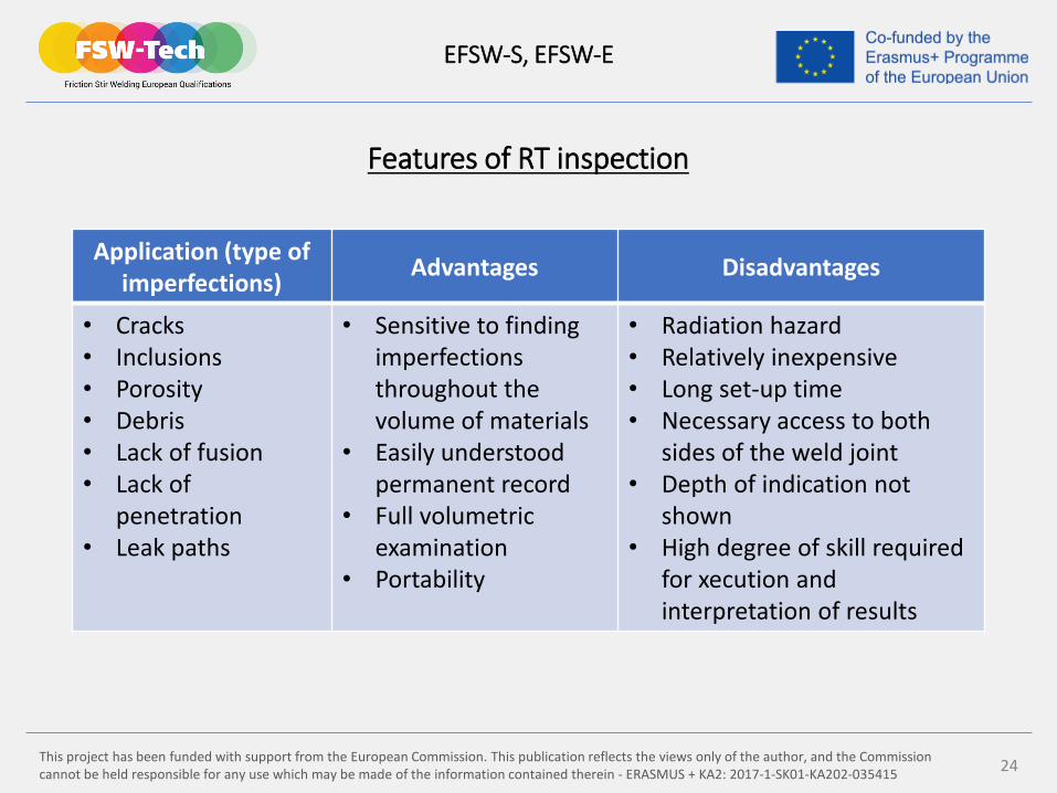
Features of RT inspection
Application (type ofimperfections) Advantages Disadvantages
• Cracks• Inclusions• Porosity• Debris• Lack of fusion• Lack of
penetration• Leak paths
• Sensitive to findingimperfectionsthroughout thevolume of materials
• Easily understoodpermanent record
• Full volumetricexamination
• Portability
• Radiation hazard• Relatively inexpensive• Long set-up time• Necessary access to both
sides of the weld joint• Depth of indication not
shown• High degree of skill required
for xecution andinterpretation of results
This project has been funded with support from the European Commission. This publication reflects the views only of the author, and the Commission cannot be held responsible for any use which may be made of the information contained therein - ERASMUS + KA2: 2017-1-SK01-KA202-035415 25
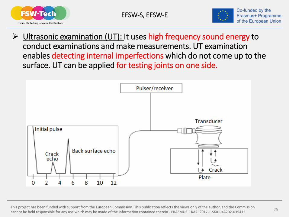
Ultrasonic examination (UT): It uses high frequency sound energy to conduct examinations and make measurements. UT examination enables detecting internal imperfections which do not come up to the surface. UT can be applied for testing joints on one side.
EFSW-S, EFSW-E
This project has been funded with support from the European Commission. This publication reflects the views only of the author, and the Commission cannot be held responsible for any use which may be made of the information contained therein - ERASMUS + KA2: 2017-1-SK01-KA202-035415 26
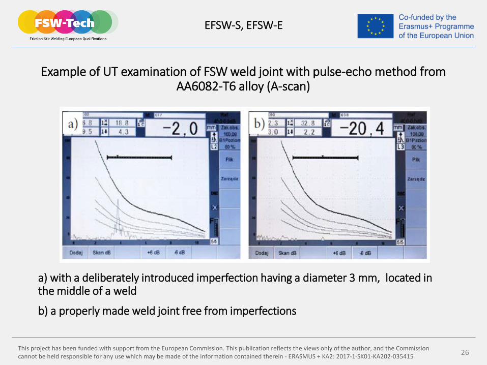
Example of UT examination of FSW weld joint with pulse-echo method from AA6082-T6 alloy (A-scan)
a) with a deliberately introduced imperfection having a diameter 3 mm, located in the middle of a weld
b) a properly made weld joint free from imperfections
EFSW-S, EFSW-E

This project has been funded with support from the European Commission. This publication reflects the views only of the author, and the Commission cannot be held responsible for any use which may be made of the information contained therein - ERASMUS + KA2: 2017-1-SK01-KA202-035415 27
Features of UT inspection
EFSW-S, EFSW-E
Application (type ofimperfections) Advantages Disadvantages
• Lack of penetration• Wormholes• Surface and
subsurfaceimperfections
• Thicknessmeasurement
• Fast method• Only single-sided access is required• Full volumetric examination• Minimal part preparation is required• Instanteneous results• Detailed images can be produced
automatically• Permanent record• Can be used for thickness
measurements
• Surface must be accessible andsmooth
• Test results depend on the operators experience
• Location of an imperfection in relation to a wave affects imperfection detectability
• Interpretation can be difficult• Need for reference standards
and calibration blocks• Difficulty with complex
geometries of weld joints• Mandatory use of couplant• Not allowed UT examination in
area of previous PT inspection

This project has been funded with support from the European Commission. This publication reflects the views only of the author, and the Commission cannot be held responsible for any use which may be made of the information contained therein - ERASMUS + KA2: 2017-1-SK01-KA202-035415 28
Eddy current testing (ET): This inspection use the principle ofelectromagnetism as the basis for conducting examinations, eddy currents are created through electromagnetic induction. When alternating current (AC) is applied to the conductor (copper wire), a magnetic field develops in and around conductor. If another conductor is brought into close proximity to changing magnetic field, current will be induced in this second conductor. In the presence of imperfection, the flow of eddy currents is disturbed, creating a perturbation in the magnetic field at the surface of the examined part.
The frequency of AC used to induce the eddy currents and the electrical conductivity of the material being inspected determines the depth and penetration of the eddy current field and the resulting depth of the examination. ET testing is a surface and near-surface method due to limited penetration of the eddy currents in the depth.
EFSW-S, EFSW-E
This project has been funded with support from the European Commission. This publication reflects the views only of the author, and the Commission cannot be held responsible for any use which may be made of the information contained therein - ERASMUS + KA2: 2017-1-SK01-KA202-035415 29
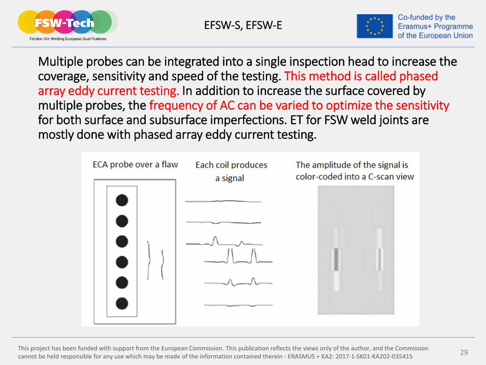
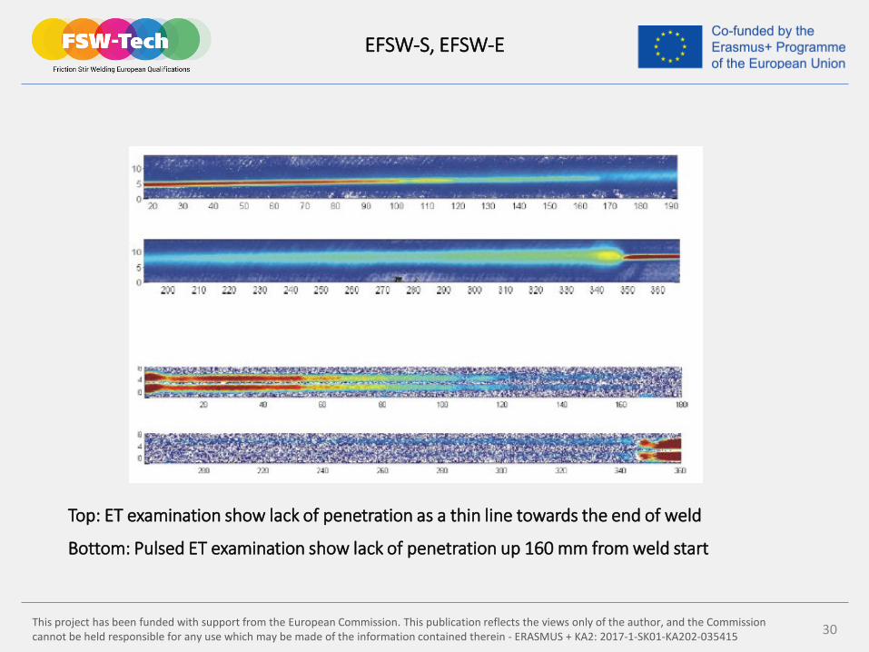
Multiple probes can be integrated into a single inspection head to increase the coverage, sensitivity and speed of the testing. This method is called phased array eddy current testing. In addition to increase the surface covered by multiple probes, the frequency of AC can be varied to optimize the sensitivityfor both surface and subsurface imperfections. ET for FSW weld joints are mostly done with phased array eddy current testing.
Phased array ET principle
EFSW-S, EFSW-E
This project has been funded with support from the European Commission. This publication reflects the views only of the author, and the Commission cannot be held responsible for any use which may be made of the information contained therein - ERASMUS + KA2: 2017-1-SK01-KA202-035415 30
Top: ET examination show lack of penetration as a thin line towards the end of weld
Bottom: Pulsed ET examination show lack of penetration up 160 mm from weld start
EFSW-S, EFSW-E
This project has been funded with support from the European Commission. This publication reflects the views only of the author, and the Commission cannot be held responsible for any use which may be made of the information contained therein - ERASMUS + KA2: 2017-1-SK01-KA202-035415 31
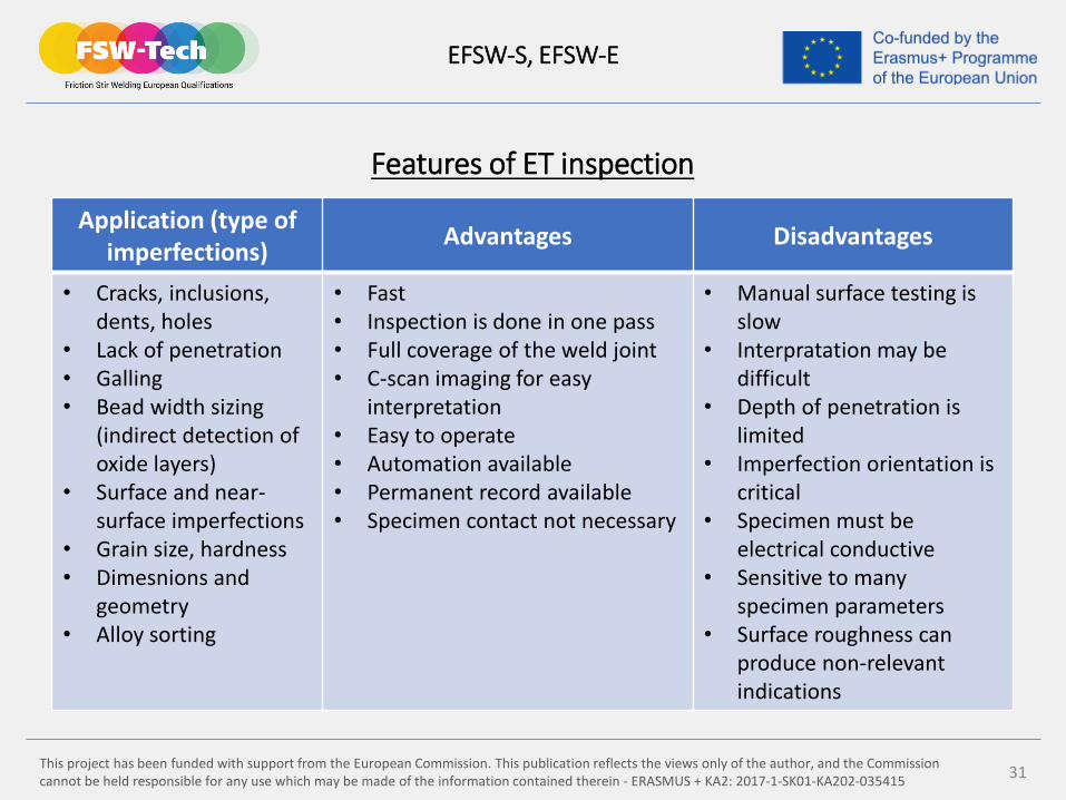
Features of ET inspection
EFSW-S, EFSW-E
Application (type ofimperfections) Advantages Disadvantages
• Cracks, inclusions, dents, holes
• Lack of penetration• Galling• Bead width sizing
(indirect detection ofoxide layers)
• Surface and near-surface imperfections
• Grain size, hardness• Dimesnions and
geometry• Alloy sorting
• Fast• Inspection is done in one pass• Full coverage of the weld joint• C-scan imaging for easy
interpretation• Easy to operate• Automation available• Permanent record available• Specimen contact not necessary
• Manual surface testing is slow
• Interpratation may be difficult
• Depth of penetration is limited
• Imperfection orientation is critical
• Specimen must be electrical conductive
• Sensitive to manyspecimen parameters
• Surface roughness canproduce non-relevantindications
This project has been funded with support from the European Commission. This publication reflects the views only of the author, and the Commission cannot be held responsible for any use which may be made of the information contained therein - ERASMUS + KA2: 2017-1-SK01-KA202-035415 32
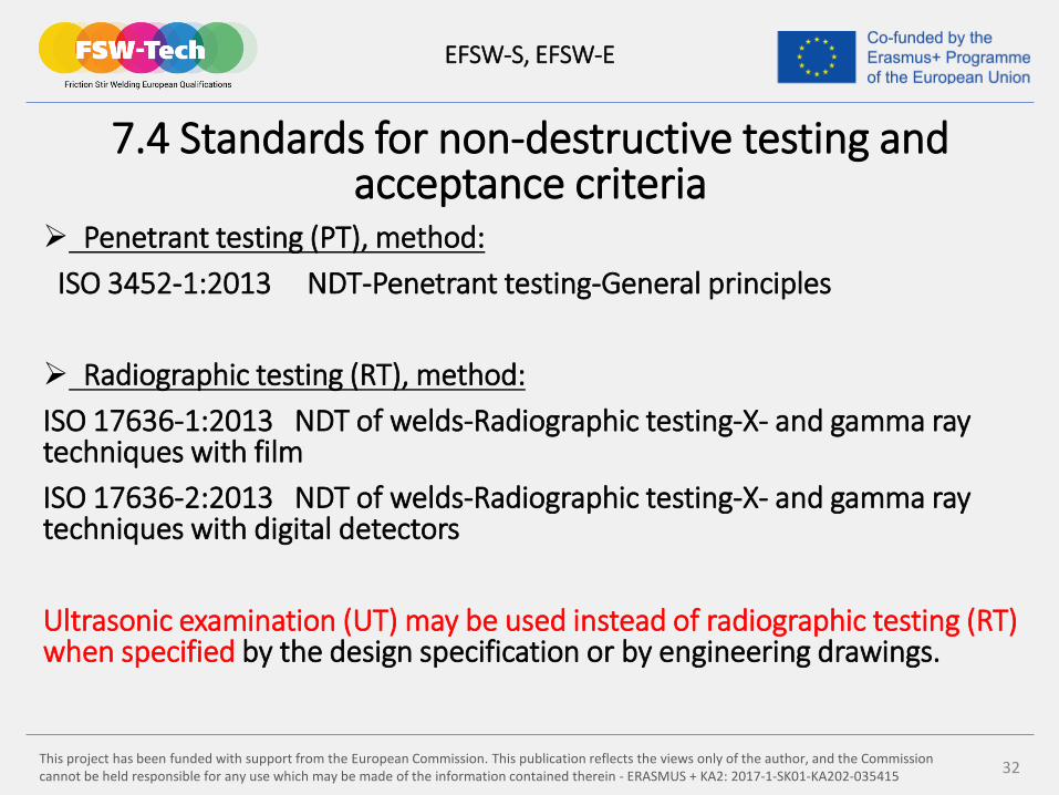
7.4 Standards for non-destructive testing andacceptance criteria
Penetrant testing (PT), method:ISO 3452-1:2013 NDT-Penetrant testing-General principles
Radiographic testing (RT), method:ISO 17636-1:2013 NDT of welds-Radiographic testing-X- and gamma raytechniques with filmISO 17636-2:2013 NDT of welds-Radiographic testing-X- and gamma raytechniques with digital detectors
Ultrasonic examination (UT) may be used instead of radiographic testing (RT) when specified by the design specification or by engineering drawings.
EFSW-S, EFSW-E
This project has been funded with support from the European Commission. This publication reflects the views only of the author, and the Commission cannot be held responsible for any use which may be made of the information contained therein - ERASMUS + KA2: 2017-1-SK01-KA202-035415 33
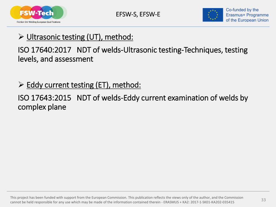
Ultrasonic testing (UT), method:
ISO 17640:2017 NDT of welds-Ultrasonic testing-Techniques, testing levels, and assessment
Eddy current testing (ET), method:
ISO 17643:2015 NDT of welds-Eddy current examination of welds bycomplex plane
EFSW-S, EFSW-E
This project has been funded with support from the European Commission. This publication reflects the views only of the author, and the Commission cannot be held responsible for any use which may be made of the information contained therein - ERASMUS + KA2: 2017-1-SK01-KA202-035415 34
Acceptance levels for all NDT methods:
ISO 23277:2015 NDT of welds-Penetrant testing-Acceptance levels
ISO 10675-2:2017 NDT of welds-Acceptance levels for radiographictesting-Aluminium and its alloys
ISO 11666:2018 NDT of welds-Ultrasonic testing-Acceptance levels
For ET examinations relevant requirements or design specificationsshall be used for determination of acceptance levels because thismethod is used when stringent requirements for weld integrity are required.
EFSW-S, EFSW-E
This project has been funded with support from the European Commission. This publication reflects the views only of the author, and the Commission cannot be held responsible for any use which may be made of the information contained therein - ERASMUS + KA2: 2017-1-SK01-KA202-035415 35
7.5 Equipment calibration and reproducibility
Calibration: Meters, gages, and dials installed on automatic, mechanized, or robotic welding apparatus shall be calibrated using an established procedure. The fabricator shall establish and document applicable calibration procedures.
Equipment capabilities and performance: Welding equipment (welding machines and FSW tools) shall be capable of producing welds that meet the acceptance criteria specified in ISO 25239-5 or AWS D17.3. The welding equipment shall be capable of maintaining weld quality and consistency.
EFSW-S, EFSW-E
This project has been funded with support from the European Commission. This publication reflects the views only of the author, and the Commission cannot be held responsible for any use which may be made of the information contained therein - ERASMUS + KA2: 2017-1-SK01-KA202-035415 36
Reproducibility tests for qualified machine welding settings: Shall be performed to demonstrate that the welding equipment can repeatedly produce welds that meet the acceptance levels in ISO 25239-5 or AWS D17.3.
Reproducibility tests shall be carried out when any of the followingoccurs:
- a critical component of the welding equipment is damaged, repaired, or replaced
- welding in an area within the working envelope of the machine where the fabricator determines a difference in machine stiffness from the location of the original qualification resulting in unacceptable welds
The reproducibility test shall be performed in accordance with a WPS that is used in production for that machine. A minimum of three test welds shall be made in succession.
EFSW-S, EFSW-E
This project has been funded with support from the European Commission. This publication reflects the views only of the author, and the Commission cannot be held responsible for any use which may be made of the information contained therein - ERASMUS + KA2: 2017-1-SK01-KA202-035415
Thank you for your attention!