Embed Size (px)
Citation preview

EUROPEAN NEW CAR ASSESSMENT PROGRAMME
(Euro NCAP)
ASSESSMENT PROTOCOL – ADULT OCCUPANT PROTECTION
Version 7.0.2
April 2015

Version 7.0.2
April 2015
Copyright 2015© Euro NCAP - This work is the intellectual property of Euro NCAP. Permission is
granted for this material to be shared for non-commercial, educational purposes, provided that this
copyright statement appears on the reproduced materials and notice is given that the copying is by
permission of Euro NCAP. To disseminate otherwise or to republish requires written permission from
Euro NCAP.

Version 7.0.2
April 2015
EUROPEAN NEW CAR ASSESSMENT PROGRAMME (Euro NCAP)
ASSESSMENT PROTOCOL – ADULT OCCUPANT PROTECTION
Table of Contents
1 INTRODUCTION .................................................................................................................... 1
2 METHOD OF ASSESSMENT ................................................................................................ 1
2.1 Points Calculation ........................................................................................................................ 2 2.1.1 Capping ................................................................................................................................................... 3
3 OFFSET DEFORMABLE BARRIER FRONTAL IMPACT ASSESSMENT ..................... 4
3.1 Criteria and Limit Values ........................................................................................................... 4 3.1.1 Head ........................................................................................................................................................ 4 3.1.2 Neck ........................................................................................................................................................ 5 3.1.3 Chest ....................................................................................................................................................... 5 3.1.4 Knee, Femur and Pelvis .......................................................................................................................... 6 3.1.5 Lower Leg ............................................................................................................................................... 6 3.1.6 Foot/Ankle .............................................................................................................................................. 6
3.2 Modifiers ...................................................................................................................................... 7 3.2.1 Driver ...................................................................................................................................................... 7 3.2.2 Passenger .............................................................................................................................................. 10 3.2.3 Door Opening during the Impact .......................................................................................................... 11 3.2.4 Door Opening Forces after the Impact .................................................................................................. 11
3.3 Scoring & Visualisation............................................................................................................. 11
4 FRONTAL FULL WIDTH IMPACT ASSESSMENT ......................................................... 13
4.1 Criteria and Limit Values ......................................................................................................... 13 4.1.1 Head ...................................................................................................................................................... 13 4.1.2 Neck ...................................................................................................................................................... 15 4.1.3 Chest ..................................................................................................................................................... 15 4.1.4 Knee, Femur and Pelvis ........................................................................................................................ 15 4.1.5 Lower Leg ............................................................................................................................................. 16
4.2 Modifiers .................................................................................................................................... 16 4.2.1 Head ...................................................................................................................................................... 16 4.2.2 Chest ..................................................................................................................................................... 18 4.2.3 Knee, Femur & Pelvis ........................................................................................................................... 18 4.2.4 Door Opening during the Impact .......................................................................................................... 18
4.3 Scoring & Visualisation............................................................................................................. 18
5 SIDE BARRIER AND POLE IMPACT ASSESSMENT ..................................................... 20
5.1 Criteria and Limit Values ......................................................................................................... 20 5.1.1 Head ...................................................................................................................................................... 20 5.1.2 Chest ..................................................................................................................................................... 20 5.1.3 Abdomen .............................................................................................................................................. 21 5.1.4 Pelvis .................................................................................................................................................... 21
5.2 Modifiers .................................................................................................................................... 21 5.2.1 Shoulder ................................................................................................................................................ 21 5.2.2 Chest & Abdomen ................................................................................................................................ 21 5.2.3 Side Head Protection Device (Pole Impact Only)................................................................................. 22

Version 7.0.2
April 2015
5.3 Scoring & Visualisation............................................................................................................. 23
6 WHIPLASH SEAT ASSESSMENT ...................................................................................... 25
6.1 Front Seat Whiplash Assessment ............................................................................................. 25 6.1.1 Criteria and Limit Values ..................................................................................................................... 25 6.1.2 Front Whiplash Modifiers ..................................................................................................................... 28
6.2 Rear Seat Whiplash Assessment .............................................................................................. 28 6.2.1 Prerequisite ........................................................................................................................................... 28 6.2.2 Criteria and Limit Values ..................................................................................................................... 29
6.3 Scoring ........................................................................................................................................ 30 6.3.1 Front Whiplash Score ........................................................................................................................... 30 6.3.2 Rear Whiplash Score ............................................................................................................................ 31
6.4 Visualisation ............................................................................................................................... 32 6.4.1 Front Whiplash Visualisation ............................................................................................................... 32 6.4.2 Rear Whiplash Visualisation................................................................................................................. 33
7 ASSESSMENT OF AEB CITY SYSTEMS .......................................................................... 34
7.1 Introduction ............................................................................................................................... 34
7.2 Definitions .................................................................................................................................. 34
7.3 Preconditions for Scoring AEB City ........................................................................................ 34
7.4 Criteria and Scoring .................................................................................................................. 34 7.4.1 Human Machine Interface (HMI) ......................................................................................................... 34 7.4.2 Autonomous Emergency Braking (AEB) ............................................................................................. 35 7.4.3 Total Score ............................................................................................................................................ 35
8 CONCEPTS BEHIND THE ASSESSMENTS ..................................................................... 37
8.1 Frontal Impact ........................................................................................................................... 37 8.1.1 Head ...................................................................................................................................................... 37 8.1.2 Neck ...................................................................................................................................................... 37 8.1.3 Chest ..................................................................................................................................................... 37 8.1.4 Abdomen .............................................................................................................................................. 38 8.1.5 Knee, Femur & Pelvis ........................................................................................................................... 38 8.1.6 Lower Leg ............................................................................................................................................. 38 8.1.7 Foot and Ankle ..................................................................................................................................... 39
8.2 Side and Pole Impact ................................................................................................................. 39
8.3 Door Opening (Front, Side, Pole Impact) ................................................................................ 39
8.4 Whiplash ..................................................................................................................................... 40 8.4.1 Geometry Assessment........................................................................................................................... 40 8.4.2 Worst Case Geometry ........................................................................................................................... 40 8.4.3 Seatback Dynamic Deflection............................................................................................................... 40 8.4.4 Dummy Artefact Loading ..................................................................................................................... 40
9 REFERENCES ...................................................................................................................... 41
APPENDIX I .................................................................................................................................. 42

Version 7.0.2
April 2015 1
EUROPEAN NEW CAR ASSESSMENT PROGRAMME (Euro NCAP)
ASSESSMENT PROTOCOL – ADULT OCCUPANT PROTECTION
1 INTRODUCTION
Euro NCAP’s original assessment protocol was developed jointly by TRL and Vehicle Safety
Consultants Ltd under contract to the UK Department of the Environment Transport and the
Regions and International Testing, respectively. Subsequent versions of the protocol have been
developed and released by the Euro NCAP Secretariat. Beginning with Version 5 important changes
have been included that have been brought about by the introduction of the overall rating scheme.
Individual documents are released for the four main areas of assessment:
Assessment Protocol – Adult Occupant Protection;
Assessment Protocol – Child Occupant Protection;
Assessment Protocol – Pedestrian Occupant Protection;
Assessment Protocol – Safety Assist;
In addition to these four assessment protocols, a separate document is provided describing the
method and criteria by which the overall safety rating is calculated on the basis of the car
performance in each of the above areas of assessment.
The following protocol deals with the assessments made in the area of Adult Occupant Protection,
in particular in the frontal offset deformable and full width impact tests, the side impact barrier test,
the pole test and the whiplash tests.
DISCLAIMER: Euro NCAP has taken all reasonable care to ensure that the information published
in this protocol is accurate and reflects the technical decisions taken by the organisation. In the
unlikely event that this protocol contains a typographical error or any other inaccuracy, Euro NCAP
reserves the right to make corrections and determine the assessment and subsequent result of the
affected requirement(s).
2 METHOD OF ASSESSMENT
The starting point for the assessment of adult occupant protection is the dummy response data
recorded in five different test configurations: frontal impact in offset and full overlap, side impact,
pole impact and (low speed) rear impact. All criteria used are calculated according to Technical
Bulletin 17. Initially, each relevant body area is given a score based on the measured dummy
parameters. These scores can be adjusted after the test based on supplementary requirements. E.g.
for frontal impact, consideration is given to whether the original score should be adjusted to reflect
occupant kinematics or sensitivity to small changes in contact location, which might influence the

Version 7.0.2
April 2015 2
protection of different sized occupants in different seating positions. The assessment also considers
the structural performance of the car by taking account of such aspects as steering wheel
displacement, pedal movement, foot well distortion and displacement of the A pillar. The
adjustments (or modifiers) based on both inspection and geometrical considerations are applied to
the body area assessments to which they are most relevant.
For frontal offset impact, the score for each body area is based on the driver data, unless part of the
passenger fared less well. It is stated that the judgement relates primarily to the driver. For frontal
full width, the score is based on driver and rear passenger. Side impact and pole impact results
relate to the struck-side occupant only, while Whiplash results cover front and rear occupants. No
attempt is made to rate the risk of life threatening injury any differently from the risk of disabling
injury. Similarly, no attempt is made to rate the risk of the more serious but less frequent injury any
differently from the risk of less serious but more frequent injury. Care has been taken to try to avoid
encouraging manufacturers from concentrating their attention on areas which would provide little
benefit in accidents.
From the information collected in the five test scenarios, individual test scores are computed for the
frontal tests, side and pole impact and whiplash protection. The adjusted score for the different body
regions is presented, in a visual format of coloured segments within a human body outline. This is
presented for the driver and front/rear seat passenger in frontal impact, for the driver in side and
pole impact and for all occupants in rear impact. Finally, for the complete area of adult occupant
protection assessment, the scores for frontal, side, pole and whiplash are summed. The resulting
Adult Occupant Protection Score is expressed as a percentage of the maximum achievable number
of points.
In addition to the basic Euro NCAP assessment, additional information is recorded and may be
reported. In future, some of these additional aspects may be added to the Euro NCAP assessment.
2.1 Points Calculation
From Phase 3, a sliding scale system of points scoring has been used to calculate points for each
measured criterion. This involves two limits for each parameter, a more demanding limit (higher
performance), below which a maximum score is obtained and a less demanding limit (lower
performance), beyond which no points are scored. In frontal, side, and pole impacts, the maximum
score for each body region is four points; for rear impact protection, it is three points*. Where a
value falls between the two limits, the score is calculated by linear interpolation.
* Neck only based on a combination of scores obtained in three individual test conditions.

Version 7.0.2
April 2015 3
2.1.1 Capping
For most tests that are part of the adult occupant protection assessment, capping limits are
maintained for criteria related to critical body regions. Exceeding a capping limit generally indicates
unacceptable high risk at injury or, in the case of the whiplash tests, an unacceptably high seat
design parameter. In all cases except for the Full Width test, this leads to loss of all points related
to the tests. In the Full Width test capping is applied only to the specific dummy where a capping
limit was exceeded. Capping limits can be equal to or higher than the lower performance limit,
depending on the test.

Version 7.0.2
April 2015 4
3 OFFSET DEFORMABLE BARRIER FRONTAL IMPACT ASSESSMENT
3.1 Criteria and Limit Values
The basic assessment criteria used for frontal impact, with the upper and lower performance limits
for each parameter, are summarised below. Where multiple criteria exist for an individual body
region, the lowest scoring parameter is used to determine the performance of that region. The lowest
scoring body region of driver or passenger is used to determine the score. For the frontal offset
deformable barrier impact, capping is applied on the critical body regions: head, neck and chest
(see 2.1.1).
3.1.1 Head
3.1.1.1 Drivers with Steering Wheel Airbags and Passengers
If a steering wheel airbag is fitted the following criteria are used to assess the protection of the head
for the driver. These criteria are always used for the passenger.
Note: HIC15 levels above 1000 have been recorded with airbags, where there is no hard contact
and no established risk of internal head injury. A hard contact is assumed if the peak resultant head
acceleration exceeds 80g or if there is other evidence of hard contact.
If there is no hard contact a score of 4 points is awarded. If there is hard contact, the following
limits are used:
Higher performance limit
HIC15 500
Resultant Acc. 3 msec exceedence 72g
Lower performance and capping limit
HIC15 700 (20% risk of injury AIS3 [1,2])
Resultant Acc. 3 msec exceedence 80g
3.1.1.2 Drivers with No Steering Wheel Airbag
If no steering wheel airbag is fitted, and the following requirements are met in the frontal impact
test:
HIC15 <700
Resultant Acc. 3 msec exceedence <80g,
then 6.8 kg spherical headform test specified in ECE Regulation 12 [3] are carried out on the
steering wheel. The tester attempts to choose the most aggressive sites to test and it is expected that

Version 7.0.2
April 2015 5
two tests will be required, one aimed at the hub and spoke junction and one at the rim and spoke
junction. The assessment is then based on the following criteria:
Higher performance limit
Resultant peak Acc. 80g
Resultant Acc. 3 msec exceedence 65g
Lower performance and capping limit
HIC15 700
Resultant peak Acc. 120g
Resultant Acc. 3 msec exceedence 80g
From the face form tests, a maximum of 2 points are awarded for performance better than the lower
limits. For values worse than the lower performance limit, no points are awarded.
The results from the worst performing test are used for the assessment. This means that for cars,
not equipped with a steering wheel airbag, the maximum score obtainable for the driver’s head is 2
points.
3.1.2 Neck
Higher performance limit
Shear 1.9kN @ 0 msec, 1.2kN @ 25 - 35msec, 1.1kN @ 45msec
Tension 2.7kN @ 0 msec, 2.3kN @ 35msec, 1.1kN @ 60msec
Extension 42Nm
Lower performance and capping limit
Shear 3.1kN @ 0msec, 1.5kN @ 25 - 35msec, 1.1kN @ 45msec*
Tension 3.3kN @ 0msec, 2.9kN @ 35msec, 1.1kN @ 60msec*
Extension 57Nm* (Significant risk of injury [4])
(*EEVC Limits)
Note: Neck Shear and Tension are assessed from cumulative exceedence plots, with the limits being
functions of time. By interpolation, a plot of points against time is computed. The minimum point
on this plot gives the score. Plots of the limits and colour rating boundaries are given in Appendix I.
3.1.3 Chest
Higher performance limit
Compression 22mm (5% risk of injury AIS3 [5])
Viscous Criterion 0.5m/sec (5% risk of injury AIS4)

Version 7.0.2
April 2015 6
Lower performance and capping limit
Compression 42mm
Viscous Criterion 1.0m/sec (25% risk of injury AIS4)
3.1.4 Knee, Femur and Pelvis
Higher performance limit
Femur compression 3.8kN (5% risk of pelvis injury [6])
Knee slider compressive displacement 6mm
Lower performance limit
Femur Compression 9.07kN @ 0msec,
7.56kN @ 10msec* (Femur fracture limit [4])
Knee slider compressive displacement 15mm* (Cruciate ligament failure limit [4,7])
(*EEVC Limit)
Note: Femur compression is assessed from a cumulative exceedence plot, with the limits being
functions of time. By interpolation, a plot of points against time is computed. The minimum point
on this plot gives the score. Plots of the limits and colour rating boundaries are given in Appendix I.
The Lumbar forces and moments are measured for monitoring purpose only.
3.1.5 Lower Leg
Higher performance limit
Tibia Index 0.4
Tibia Compression 2kN
Lower performance limit
Tibia Index 1.3*
Tibia Compression 8kN* (10% risk of fracture [4,8])
(*EEVC Limits)
3.1.6 Foot/Ankle
Higher performance limit
Pedal rearward displacement 100mm
Lower performance limit
Pedal rearward displacement 200mm

Version 7.0.2
April 2015 7
Notes:
1. Pedal displacement is measured for all pedals with no load applied to them.
2. If any of the pedals are designed to completely release from their mountings during the impact,
no account is taken of the pedal displacement provided that release occurred in the test and
that the pedal retains no significant resistance to movement.
3. If a mechanism is present to move the pedal forwards in an impact, the resulting position of the
pedal is used in the assessment.
4. The passenger’s foot/ankle protection is not currently assessed.
3.2 Modifiers
3.2.1 Driver
The score generated from driver dummy data may be modified where the protection for different
sized occupants or occupants in different seating positions, or accidents of slightly different
severity, can be expected to be worse than that indicated by the dummy readings or deformation
data alone. There is no limit to the number of modifiers that can be applied. The concepts behind
the modifiers are explained in Section 8.
3.2.1.1 Head
Unstable Contact on the Airbag
If during the forward movement of the head its centre of gravity moves further than the outside
edge of the airbag, head contact is deemed to be unstable. The score is reduced by one point. If for
any other reason head protection by the airbag is compromised, such as by detachment of the
steering wheel from the column, or bottoming-out of the airbag by the dummy head, the modifier
is also applied.
Note: Head bottoming-out is defined as follows: There is a definite rapid increase in the slope of
one or more of the head acceleration traces, at a time when the dummy head is deep within the
airbag. The acceleration spike associated with the bottoming out should last for more than 3ms.The
acceleration spike associated with the bottoming out should generate a peak value more than 5 g
above the likely level to have been reached if the spike had not occurred. This level will be
established by smooth extrapolation of the curve between the start and end of the bottoming out
spike.
Hazardous Airbag Deployment
If, within the head zone, the airbag unfolds in a manner in which a flap develops, which sweeps
across the face of an occupant vertically or horizontally the -1 point modifier for unstable airbag
contact will be applied to the head score. If the airbag material deploys rearward, within the “head
zone” at more than 90 m/s, the -1 point modifier will be applied to the head score. Further details
are contained in Euro NCAP Technical Bulletin TB 001.

Version 7.0.2
April 2015 8
Incorrect Airbag Deployment
Any airbag(s) which does not deploy fully in the designed manner will attract a -1 point modifier
applicable to each of the most relevant body part(s) for the affected occupant. For example, where
a steering wheel mounted airbag is deemed to have deployed incorrectly, the penalty will be applied
to the frontal impact driver’s head (-1). Where, a passenger knee airbag fails to deploy correctly,
the penalty will be applied to the frontal impact passenger left and right knee, femur and pelvis (-
1).
Where the incorrect deployment affects multiple body parts, the modifier will be applied to each
individual body part. For example, where a seat or door mounted side airbag, that is intended to
provide protection to the head as well as the thorax, abdomen or pelvis deploys incorrectly, the
penalty will be applied to two body regions, -1 to the head and -1 to the chest.
The modifier(s) will be applied to the scores of the impacts for which the airbag was intended to
offer protection, regardless of the impact in which it deployed incorrectly. For example, the penalty
will be applied to the side and pole impact scores if a side protection airbag deploys incorrectly
during the frontal crash. Where any frontal protection airbag deploys incorrectly, Euro NCAP will
not accept knee mapping data for that occupant.
Unstable Contact on a Steering Wheel without an Air Bag
If, during the forward movement of the head, its centre of gravity moves radially outwards further
than the outside edge of the steering wheel rim, head contact is deemed to be unstable. The score
is reduced by one point. If for any other reason head contact on the steering wheel is unstable, such
as detachment of the steering wheel from the column, the modifier is also applied.
Displacement of the Steering Column
The score is reduced for excessive rearward, lateral or upward static displacement of the top end of
the steering column. Up to 90 percent of the EEVC limits, there is no penalty. Beyond 110 percent
of the EEVC limits, there is a penalty of one point. Between these limits, the penalty is generated
by linear interpolation. The EEVC recommended limits are: 100mm rearwards, 80mm upwards and
100mm lateral movement. The modifier used in the assessment is based on the worst of the
rearward, lateral and upward penalties.
3.2.1.2 Chest
Displacement of the A Pillar
The score is reduced for excessive rearward displacement of the driver’s front door pillar, at a height
of 100mm below the lowest level of the side window aperture. Up to 100mm displacement there is
no penalty. Above 200mm there is a penalty of two points. Between these limits, the penalty is
generated by linear interpolation.
Version 7.0.2
April 2015 9
Integrity of the Passenger Compartment
Where the structural integrity of the passenger compartment is deemed to have been compromised,
a penalty of one point is applied. The loss of structural integrity may be indicated by characteristics
such as:
Door latch or hinge failure, unless the door is adequately retained by the door frame.
Buckling or other failure of the door resulting in severe loss of fore/aft compressive strength.
Separation or near separation of the cross facia rail to A pillar joint.
Severe loss of strength of the door aperture.
When this modifier is applied, Euro NCAP will not accept knee mapping data.
Steering Wheel Contact
Where there is obvious direct loading of the chest from the steering wheel, a one point penalty is
applied.
Shoulder belt load (Driver and Front Passenger)
Where the shoulder belt load measured, exceeds 6kN a two point penalty is applied.
3.2.1.3 Knee, Femur & Pelvis
Variable Contact
The position of the dummy’s knees is specified by the test protocol. Consequently, their point of
contact on the facia is pre-determined. This is not the case with human drivers, who may have their
knees in a variety of positions prior to impact. Different sized occupants and those seated in
different positions may also have different knee contact locations on the facia and their knees may
penetrate into the facia to a greater extent. In order to take some account of this, a larger area of
potential knee contact is considered. If contact at other points, within this greater area, would be
more aggressive penalties are applied.
The area considered extends vertically 50mm above and below the maximum height of the actual
knee impact location [8]. Vertically upwards, consideration is given to the region up to 50mm above
the maximum height of knee contact in the test. If the steering column has risen during the test it
may be repositioned to its lowest setting if possible. Horizontally, for the outboard leg, it extends
from the centre of the steering column to the end of the facia. For the inboard leg, it extends from
the centre of the steering column the same distance inboard, unless knee contact would be prevented
by some structure such as a centre console. Over the whole area, an additional penetration depth of
20mm is considered, beyond that identified as the maximum knee penetration in the test. The region
considered for each knee is generated independently. Where, over these areas and this depth, femur
loads greater that 3.8kN and/or knee slider displacements greater than 6mm would be expected, a
one point penalty is applied to the relevant leg.

Version 7.0.2
April 2015 10
Concentrated Loading
The biomechanical tests which provided the injury tolerance data were carried out using a padded
impactor which spread the load over the knee. Where there are structures in the knee impact area
which could concentrate forces on part of the knee a one point penalty is applied to the relevant leg.
Where a manufacturer is able to show, by means of acceptable test data, that the Variable Contact
and/or Concentrated Loading modifiers should not be applied, the penalties may be removed.
If the Concentrated load modifier is not applied to either of the driver's knees, the left and right
knee zones (defined above) will both be split into two further areas, a ‘column’ area and the rest of
the facia. The column area for each knee will extend 60mm from the centreline of the steering
column and the remainder of the facia will form the other area for each knee. As a result, the one
point penalty for Variable Contact will be divided into two with one half of a point being applied
to the column area and one half of a point to the remainder of the facia for each knee.
3.2.1.4 Lower Leg
Upward Displacement of the Worst Performing Pedal
The score is reduced for excessive upward static displacement of the pedals. Up to 90 percent of
the limit considered by EEVC, there is no penalty. Beyond 110 percent of the limit, there is a penalty
of one point. Between these limits, the penalty is generated by linear interpolation. The limit agreed
by EEVC was 80mm.
3.2.1.5 Foot & Ankle
Footwell Rupture
The score is reduced if there is significant rupture of the footwell area. This is usually due to
separation of spot welded seams. A one point penalty is applied for footwell rupture. The footwell
rupture may either pose a direct threat to the driver’s feet or be sufficiently extensive to threaten
the stability of footwell response. When this modifier is applied, Euro NCAP will not accept knee
mapping data.
Pedal Blocking
Where the rearward displacement of a ‘blocked’ pedal exceeds 175mm relative to the pre-test
measurement, a one point penalty is applied to the driver’s foot and ankle assessment. A pedal is
blocked when the forward movement of the intruded pedal under a load of 200N is <25mm.
Between 50mm and 175mm of rearward displacement the penalty is calculated using a sliding scale
between 0 to 1 points.
3.2.2 Passenger
The score generated from passenger dummy data may be modified where the protection for
different sized occupants or occupants in different seating positions, or accidents of slightly
different severity, can be expected to be worse than that indicated by the dummy readings alone.

Version 7.0.2
April 2015 11
There is no limit to the number of modifiers that can be applied. The concepts behind the modifiers
are explained in section 7. The modifiers applicable to the passenger are:
Unstable Contact on the airbag
Hazardous airbag deployment
Shoulder belt load
Incorrect airbag deployment
Knee, Femur & Pelvis, Variable Contact
Knee, Femur & Pelvis, Concentrated loading
The assessments airbag stability, head bottoming-out (where present) and the knee impact areas are
the same as for driver. For the outboard knee, the lateral range of the knee impact area extends from
the centre line of the passenger seat to the outboard end of the facia. For the inboard knee, the area
extends the same distance inboard of the seat centre line, unless knee contact is prevented by the
presence of some structure such as the centre console. The passenger knee zones and penalties will
not be divided into two areas even if the concentrated load modifier is not applied.
3.2.3 Door Opening during the Impact
When a door opens in the test, a minus one-point modifier will be applied to the score for that test.
The modifier will be applied to the frontal impact assessment for every door (including tailgates
and moveable roofs) that opens. The number of door opening modifiers that can be applied to the
vehicle score is not limited.
3.2.4 Door Opening Forces after the Impact
The force required to unlatch and open each side door to an angle of 45 degrees is measured after
the impact. A record is also made of any doors which unlatch or open in the impact. Currently, this
information is not used in the assessment but it may be referred to in the text of the published
reports.
Door opening forces are categorised as follows:
Opens normally Normal hand force is sufficient
Limited force 100N
Moderate force > 100N to < 500N
Extreme hand force 500N
Tools had to be used Tools necessary
3.3 Scoring & Visualisation
The protection provided for adults for each body region are presented visually, using coloured
segments within body outlines. The colour used is based on the points awarded for that body region
(rounded to three decimal places), as follows:

Version 7.0.2
April 2015 12
Green ‘Good’ 4.000 points
Yellow ‘Adequate’ 2.670 - 3.999 points
Orange ‘Marginal’ 1.330 - 2.669 points
Brown ‘Weak’ 0.001 - 1.329 points
Red ‘Poor’ 0.000 points
For frontal impact, the body regions are grouped together, with the score for the grouped body
region being that of the worst performing region or limb. The grouped regions are: Head and Neck
(4 points), Chest (4 points), Knee, Femur, Pelvis (i.e. left and right femur and knee slider) (4 points)
and Leg and Foot (i.e. left and right lower leg and foot and ankle) (4 points). Results are shown
separately for driver and passenger.
The contribution of the frontal impact test to the Adult Occupant Protection Score is calculated by
summing the body scores for the relevant body regions, taking the lower of the driver and passenger
scores for each region (16 points total). This score is halved with a total achievable score of 8 points.

Version 7.0.2
April 2015 13
4 FRONTAL FULL WIDTH IMPACT ASSESSMENT
4.1 Criteria and Limit Values
The basic assessment criteria used for the full width frontal impact test, with the upper and lower
performance limits for each parameter, are summarised below. Where multiple criteria exist for an
individual body region, the lowest scoring parameter is used to determine the performance of that
region. This does however not apply to the neck assessment for the rear passenger dummy. The
scoring for the rear passenger neck is detailed in section 4.1.2.
The full width test is performed with a driver and rear passenger dummy as standard. The OEM is
requested to provide data for the front passenger(s) from the same test set-up to demonstrate similar
protection levels for all occupants seated in the front row. In cases where the OEM is not willing or
able to provide this data, Euro NCAP may perform the full width test with an additional HIII-05F
dummy in the front passenger seat.
Note: The front passenger data needs to be provided to the Euro NCAP Secretariat at least
one week before the full width test is performed.
4.1.1 Head
4.1.1.1 Drivers with Steering Wheel Airbags and Passengers
If a steering wheel airbag is fitted the following criteria are used to assess the protection of the head
for the driver. These criteria are always used for the passenger.
Note: HIC15 levels above 700 have been recorded with airbags, where there is no hard
contact and no established risk of internal head injury. A hard contact is assumed, if the peak
resultant head acceleration exceeds 80g, or if there is other evidence of hard contact.
If there is no hard contact a score of 4 points is awarded. If there is hard contact, the following
limits are used:
Higher performance limit
HIC15 500
Resultant Acc. 3 msec exceedence 72g
Lower performance and capping limit
HIC15 700
Resultant Acc. 3 msec exceedence 80g
Version 7.0.2
April 2015 14
4.1.1.2 Drivers with No Steering Wheel Airbag
If no steering wheel airbag is fitted, and the following requirements are met in the frontal impact
test:
HIC15 <700
Resultant Acc. 3 msec exceedence <80g,
then 6.8 kg spherical headform test specified in ECE Regulation 12 [3] are carried out on the
steering wheel. The tester attempts to choose the most aggressive sites to test and it is expected that
two tests will be required, one aimed at the hub and spoke junction and one at the rim and spoke
junction. The assessment is then based on the following criteria:
Higher performance limit
Resultant peak Acc. 80g
Resultant Acc. 3 msec exceedence 65g
Lower performance and capping limit
HIC15 700
Resultant peak Acc. 120g
Resultant Acc. 3 msec exceedence 80g
From the face form tests, a maximum of 2 points are awarded for performance better than the lower
limits. For values worse than the lower performance limit, no points are awarded.
The results from the worst performing test are used for the assessment. This means that for cars,
not equipped with a steering wheel airbag, the maximum score obtainable for the driver’s head is 2
points.
4.1.1.3 Rear Passenger
If there is no hard contact seen on the high speed film, the score is based on the 3ms resultant
acceleration.
Higher performance limit
Resultant Acc. 3 msec exceedence 72g
Lower performance and capping limit
Resultant Acc. 3 msec exceedence 80g
If there is hard contact confirmed on the high speed film, the following limits are used:
Higher performance limit
HIC15 500

Version 7.0.2
April 2015 15
Resultant Acc. 3 msec exceedence 72g
Lower performance and capping limit
HIC15 700
Resultant Acc. 3 msec exceedence 80g
4.1.2 Neck
Higher performance limit
Shear 1.2kN
Tension 1.7kN
Extension 36Nm
Lower performance
Shear 1.95kN
Tension 2.62kN
Extension 49Nm
Capping limit (driver only)
Shear 2.7kN
Tension 2.9kN
Extension 57Nm
For the rear passenger dummy, the neck score is the sum of all three criteria, with the following
maximum score per criterion:
Shear 1 point
Tension 1 point
Extension 2 points
4.1.3 Chest
Higher performance limit
Compression 18mm
Viscous Criterion 0.5m/sec
Lower performance and Capping limit
Compression 42mm
Viscous Criterion 1.0m/sec
4.1.4 Knee, Femur and Pelvis
The knee, femur, pelvis region is assessed by the femur compression:

Version 7.0.2
April 2015 16
Higher performance limit
Femur compression 2.6kN
Lower performance limit
Femur Compression 6.2kN
The knee slider displacement and the Lumbar forces and moments are measured for monitoring
purpose only.
4.1.5 Lower Leg
The Lower Legs are measured for monitoring purpose only.
4.2 Modifiers
The score generated from dummy data may be modified where the protection for different sized
occupants or occupants in different seating positions, or accidents of slightly different severity, can
be expected to be worse than that indicated by the dummy readings or deformation data alone.
There is no limit to the number of modifiers that can be applied.
4.2.1 Head
Unstable Contact on the Airbag (Driver and Rear Passenger)
If during the forward movement of the head its centre of gravity moves further than the outside
edge of the airbag, head contact is deemed to be unstable. The score is reduced by one point. If for
any other reason head protection by the airbag is compromised, such as by detachment of the
steering wheel from the column, or bottoming-out of the airbag by the dummy head, the modifier
is also applied.
Note: Head bottoming-out is defined as follows: There is a definite rapid increase in the slope
of one or more of the head acceleration traces, at a time when the dummy head is deep within
the airbag. The acceleration spike associated with the bottoming out should last for more
than 3ms.The acceleration spike associated with the bottoming out should generate a peak
value more than 5 g above the likely level to have been reached if the spike had not occurred.
This level will be established by smooth extrapolation of the curve between the start and end
of the bottoming out spike.
Hazardous Airbag Deployment (Driver and Rear Passenger)
If, in the ODB test, the airbag was seen to unfold in a manner in which a flap develops, which
sweeps across the face of an occupant vertically or horizontally the -1 point modifier for unstable
airbag contact will be applied to the head score. Also, when the airbag material deployed rearward,
within the “head zone” at more than 90 m/s in the ODB test, the -1 point modifier will be applied
to the head score. Further details are contained in Euro NCAP Technical Bulletin TB 001.

Version 7.0.2
April 2015 17
Incorrect Airbag Deployment (Driver and Rear Passenger)
Any airbag(s) which does not deploy fully in the designed manner will attract a -1 point modifier
applicable to each of the most relevant body part(s) for the affected occupant. For example, where
a steering wheel mounted airbag is deemed to have deployed incorrectly, the penalty will be applied
to the frontal impact driver’s head (-1). Where, a passenger knee airbag fails to deploy correctly,
the penalty will be applied to the frontal impact passenger left and right knee, femur and pelvis (-
1).
Where the incorrect deployment affects multiple body parts, the modifier will be applied to each
individual body part. For example, where a seat or door mounted side airbag, that is intended to
provide protection to the head as well as the thorax, abdomen or pelvis deploys incorrectly, the
penalty will be applied to two body regions, -1 to the head and -1 to the chest.
The modifier(s) will be applied to the scores of the impacts for which the airbag was intended to
offer protection, regardless of the impact in which it deployed incorrectly. For example, the penalty
will be applied to the side and pole impact scores if a side protection airbag deploys incorrectly
during the frontal crash. Where any frontal protection airbag deploys incorrectly, Euro NCAP will
not accept knee mapping data for that occupant.
Unstable Contact on a Steering Wheel without an Airbag (Driver)
If, during the forward movement of the head, its centre of gravity moves radially outwards further
than the outside edge of the steering wheel rim, head contact is deemed to be unstable. The score
is reduced by one point. If for any other reason head contact on the steering wheel is unstable, such
as detachment of the steering wheel from the column, the modifier is also applied.
Displacement of the Steering Column (Driver)
The score is reduced for excessive rearward, lateral or upward static displacement of the top end of
the steering column. Up to 90 percent of the EEVC limits, there is no penalty. Beyond 110 percent
of the EEVC limits, there is a penalty of one point. Between these limits, the penalty is generated
by linear interpolation. The EEVC recommended limits are: 100mm rearwards, 80mm upwards and
100mm lateral movement. The modifier used in the assessment is based on the worst of the
rearward, lateral and upward penalties.
Exceeding forward excursion line (Rear Passenger)
The score is reduced for excessive forward excursion. Where the head of the Rear Passenger
exceeds the 450mm or 550mm forward excursion line as defined in the full width test protocol, a 2
or 4 point modifier respectively is applied. The modifier can be removed when it is shown by means
of numerical simulation or a sled test that the HIII-50M does not contact the front passenger seat
when in the 50M seating position, or when the HIC15 value is below 700 in case of contact with the
front passenger seat.

Version 7.0.2
April 2015 18
4.2.2 Chest
Steering Wheel Contact (Driver)
Where there is obvious direct loading of the chest from the steering wheel, a one point penalty is
applied.
Shoulder belt load (Driver and Rear Passenger)
Where the shoulder belt load measured, exceeds 6kN a two point penalty is applied.
4.2.3 Knee, Femur & Pelvis
Submarining (Driver and Rear Passenger)
The score for the Knee, Femur & Pelvis is reduced by 4 points when submarining occurs. The
modifier is applied when a 1kN drop in any of the two iliac forces measured is seen within 1 ms
and when the submarining is confirmed on the high speed film.
4.2.4 Door Opening during the Impact
When a door opens in the test, a minus one-point modifier will be applied to the score for that test.
The modifier will be applied to the frontal impact assessment for every door (including tailgates
and moveable roofs) that opens. The number of door opening modifiers that can be applied to the
vehicle score is not limited.
4.3 Scoring & Visualisation
The scores for the driver and rear passenger dummy are averaged. For the Full Width frontal impact,
capping is applied on the critical body regions: head, neck (driver only) and chest.
To ensure similar levels of protection for all occupants, the total dummy score (excluding modifiers)
of the front passenger (based on manufacturer provided data) may not be less than 90% of that of
total score of the driver. When this requirement is not met, the front row will be assessed using the
worst performing body region of the driver and front passenger.
The protection provided for adults for each body region are presented visually, using coloured
segments within body outlines. The colour used is based on the points awarded for that body region
(rounded to three decimal places), as follows:
Green ‘Good’ 4.000 points
Yellow ‘Adequate’ 2.670 - 3.999 points
Orange ‘Marginal’ 1.330 - 2.669 points
Brown ‘Weak’ 0.001 - 1.329 points
Red ‘Poor’ 0.000 points

Version 7.0.2
April 2015 19
For frontal impact, the body regions are grouped together, with the score for the grouped body
region being that of the worst performing region or limb. The grouped regions are: Head (4 points),
Neck (4 points), Chest (4 points) and Knee, Femur & Pelvis (i.e. left and right femur) (4 points).
Results are shown separately for driver and rear passenger.
To ensure similar levels of protection for all occupants, the dummy score of the front passenger
may not be less than 90% of that of the driver. The front passenger data needs to be provided to the
Euro NCAP Secretariat before the full width test is performed. When this requirement is not met,
the front row will be assessed using the worst performing body region of the driver and front
passenger.
The contribution of the frontal impact test to the Adult Occupant Protection Score is calculated by
summing the body scores for the relevant body regions and calculating the average of the driver
and rear passenger scores (total of 16 points each) and dividing it by two. The total achievable score
for the Full Width test is 8 points.

Version 7.0.2
April 2015 20
5 SIDE BARRIER AND POLE IMPACT ASSESSMENT
5.1 Criteria and Limit Values
The basic assessment criteria used for both side barrier and pole impacts, with the upper and lower
performance limits for each parameter, are summarised below. The assessments are divided into
four individual body regions, the head, chest, abdomen and pelvis. The criteria and limits are equal
for side barrier and pole test except for the head and chest. A maximum of four points are available
for each body region. Where multiple criteria exist for an individual body region, the lowest scoring
parameter is used to determine the performance of that region. There is no limit to the number of
modifiers that can be applied. The concepts behind the modifiers are explained in section 8.
For both side and pole impacts, capping is applied on the head, chest, abdomen and pelvis. Where
no head protection systems are present, the pole test will not be allowed and the points for that test
are set to zero.
Note: The requirement is for the fitment of a head protection system, meaning that the
manufacturer is free to use a solution other than an airbag. However, for technologies other
than conventional curtain or head airbags, the manufacturer is requested to provide
evidence that the system is effective, at least in principle, before a test can be allowed.
5.1.1 Head
5.1.1.1 Side impact
Higher performance limit
HIC15 500
Resultant Acc. 3 msec exceedence 72g
Lower performance and capping limit
HIC15 700 (20% risk of injury AIS3 [1,2])
Resultant Acc. 3 msec exceedence 80g
5.1.1.2 Pole impact
Capping limits
HIC15 <700
Peak Resultant Acc <80g
No direct head contact with the pole
5.1.2 Chest
The assessment is based on the worst performing individual rib lateral compression.

Version 7.0.2
April 2015 21
MDB and Pole Higher performance limit
Lateral Compression 28mm (5% risk of AIS3, 67YO)
MDB Lower performance and capping limit
Lateral Compression 50mm (30% risk of AIS3, 45YO)
Pole Lower performance limit
Lateral Compression 50mm (30% risk of AIS3, 45YO)
Pole Capping limit
Lateral Compression 55mm (50% risk of AIS3, 45YO)
5.1.3 Abdomen
Higher performance limit
Lateral Compression 47mm (33% risk of AIS3, 67YO)
Lower performance and capping limit
Lateral Compression 65mm
5.1.4 Pelvis
Higher performance limit
Pubic Symphysis Force 1.7kN (5% risk of AIS3, 67YO)
Lower performance and capping limit
Pubic Symphysis Force 2.8kN (20% risk of AIS3, 45YO)
5.2 Modifiers
5.2.1 Shoulder
Where the shoulder lateral force (Y direction) component is 3.0kN or above, no points will be
awarded for the chest assessment.
5.2.2 Chest & Abdomen
Where the viscous criterion (V*C) is 1.0m/s or above for the chest, abdomen or both, no points will
be awarded for the relevant body region assessment.

Version 7.0.2
April 2015 22
5.2.3 Side Head Protection Device (Pole Impact Only)
Vehicles equipped with head protection side airbags, curtain, seat mounted or any other, will have
the inflated energy absorbing areas evaluated by means of a geometric assessment. The airbags
must provide protection for a range of occupant sizes in both the front and the rear on both sides of
the vehicle. Where a vehicle does not offer sufficient protection, a penalty of -4 shall be applied to
the overall pole impact score. Any vehicle that does not provide a head protection device covering
the front and rear seat positions on both sides of the vehicle will also attract this modifier.
Where a vehicle is only equipped with separate head protecting devices for front and rear occupants,
on both sides of the vehicle, and is considered as having limited space in the rear seats†, the penalty
will be -2 points for each seat row (max -4 points).
5.2.3.1 Coverage areas
To ensure adequate head protection is offered, the head protection device coverage is assessed in
the geometric area, or the Head Protection Device (HPD) assessment zone, where the occupant
head would most likely impact side structures. If the vehicle is equipped with movable rear seats
the seat shall be set to the most rearward position. If there is a third row of fixed seats, these will
be included in the assessment unless they are per manufacturers’ recommendation not suitable for
adult occupation (handbook).
5.2.3.2 Application
Where the airbags differ between the left and right hand sides of the vehicle, the airbags on both
sides of the vehicle will be evaluated and the assessment will be based upon worst performing side.
All areas of the airbag, both front and rear, will be evaluated and the assessment will be based upon
the worst performing part of any of the airbags.
5.2.3.3 Exclusions
The head protecting airbags should cover all glazed areas within the defined zone up to the edge of
door daylight opening (FMVSS201) where it meets the roofline, B-pillar, C-pillar and door
waistline. Seams in the airbag will not be penalised provided that the un-inflated area is no wider
than 15mm. Any other areas where the airbag layers are connected will not be penalised provided
that the surrounding areas are inflated and any un-inflated areas are no larger than 50mm in diameter
or equivalent area or the sum of the major and minor axes of individual areas does not exceed
† Vehicles will be considered as having limited rear space when the normal CRSs recommended by the manufacturer
cannot be installed with the front seats in the test position. Where this is the case, the vehicle manufacturer should
provide evidence showing that the CRS and/or child cannot be installed without interference from the vehicle.
Version 7.0.2
April 2015 23
100mm. In the case that the un-inflated area would be larger than described above, the OEM shall
provide data to demonstrate sufficient energy absorption is guaranteed.
Where a vehicle is fitted with a third row of foldable or removable seats, the third row (only) will
be excluded from the assessment.
5.2.4 Incorrect Airbag Deployment
Any airbag(s) which does not deploy fully in the designed manner will attract a -1 point modifier
applicable to each of the most relevant body part(s) for the affected occupant. For example, where
a head curtain airbag is deemed to have deployed incorrectly, the penalty will be applied to the side
impact driver’s head (-1). Where the incorrect deployment affects multiple body parts, the modifier
will be applied to each individual body part. For example, where a seat or door mounted side airbag
fails to deploy correctly that is intended to provide protection to the head as well as the thorax,
abdomen and pelvis, the penalty will be applied to two body regions, the head (-1) and the chest (-
1). The two penalties would also be applicable to both the side and pole impacts, which are scaled
down in the final vehicle rating.
The modifier will be applied even if the airbag was not intended to offer protection in that particular
impact. For example, the penalty will be applied if a driver’s knee airbag deploys incorrectly in a
side or pole impact. In this case the modifier will be applied to both frontal impact driver knee,
femur and pelvis body parts. Where a frontal protection airbag deploys incorrectly, knee-mapping
is not permitted for the occupant whom the airbag was designed to protect.
5.2.5 Door Opening during the Impact
When a door opens in the test, a minus one-point modifier will be applied to the score for that test.
The modifier will be applied to the side impact assessment score for every door (including tailgates
and moveable roofs) that opens. The number of door opening modifiers that can be applied to the
vehicle score is not limited.
5.2.6 Door Opening Forces after the Impact
A check is made to ensure that the doors on the non-struck side can be opened. The doors on the
struck side are not opened.
5.3 Scoring & Visualisation
The protection provided for adults for each body region are presented visually, using coloured
segments within body outlines. The colour used is based on the points awarded for that body region
(rounded to three decimal places), as follows:

Version 7.0.2
April 2015 24
Green ‘Good’ 4.000 points
Yellow ‘Adequate’ 2.670 - 3.999 points
Orange ‘Marginal’ 1.330 - 2.669 points
Brown ‘Weak’ 0.001 - 1.329 points
Red ‘Poor’ 0.000 points
For the side barrier and pole impacts, all the individual regions are used. Results are shown
separately for side barrier and pole impact.
The contribution of the side and pole impact tests to the Adult Occupant Protection Score is
calculated by summing the body scores for the relevant body regions in each of the tests. The total
score in side barrier and pole tests together is limited to 16 points. This is achieved by adding up
the individual scores (after modifiers have been applied) for the side impact test (max. 16 points)
and the pole test (max. 16 points) and dividing the result by two.

Version 7.0.2
April 2015 25
6 WHIPLASH SEAT ASSESSMENT
Whiplash is assessed for both the front seats and the rear outboard seats. Front seats are tested
statically and dynamically according to Euro NCAP Whiplash Testing Protocol. Rear seats are
assessed according to the Euro NCAP Rear Whiplash Protocol. The details of the front seat(s) that
will be tested by Euro NCAP are contained in Section 3.2.5 of the Euro NCAP Vehicle
Specification, Sponsorship, Testing and Re-testing Protocol.
6.1 Front Seat Whiplash Assessment
6.1.1 Criteria and Limit Values
The basic assessment criteria used for front whiplash protection assessment, with the upper and
lower performance limits for each parameter, are summarised below.
6.1.1.1 Static Assessments
6.1.1.1.1 Head Restraint Geometry Assessment
The assessment is based on the worst performing parameter from either the height or backset:
Higher performance limit:
Height: 0mm below top height of HPM & HRMD
Backset: 40mm
Lower performance limit:
Height: 80mm below top height of HPM & HRMD
Backset: 100mm
The geometric assessment will be based on the average height and backset taken from at least 9
measurements obtained across all of the seats provided for assessment. A minimum of three drops
per seat shall be performed to ensure consistent measurements are obtained on each individual seat.
Where obvious outlying HRMD/HPM measurements occur, further installations shall be
undertaken on that seat to ascertain whether differences are due to the individual installation or seat
to seat variability. Where a seat has a non-reversible head restraint and qualifies for a geometric
assessment in the deployed position, additional seats shall be provided by the vehicle manufacturer
for measurement.
The geometry assessment has two points allocated to it ranging from plus one to minus one.

Version 7.0.2
April 2015 26
6.1.1.1.2 Worst Case Geometry‡
1/n points (where n = the number of front seats) will be available for each front seat scoring more
than 0 points in the worst case geometry assessment. For seats where the occupant must adjust the
head restraint, the worst case geometry shall be measured in the lowest and rearmost position
regardless of whether or not the seat is equipped with an active head restraint. The assessment will
be based on the average height and backset taken from at least 9 measurements in the down and
back position obtained across all of the seats provided for assessment. A minimum of 3 drops per
seat shall be performed to ensure consistent measurements are obtained on each individual seat.
Alternatively, a means of ensuring that the head restraint is correctly positioned for different sized
occupants without specific occupant action shall be offered. For these automatically adjusting head
restraints, the worst case geometry assessment shall be measured in the position as obtained in
Section 5.6 of the Euro NCAP Whiplash Testing Protocol. This credit will only be available to seats
performing well dynamically, with a raw score greater than 4.50 points after capping and all
modifiers have been applied.
For the dynamic test of self adjusting head restraints, the seat should be set in the position as
obtained in Section 5.6. of the Euro NCAP Whiplash Testing Protocol and the corresponding head
restraint height should be used irrespective of whether this is the mid height position of the head
restraint itself.
The individual front seats are scored separately for this feature as cars have been encountered in
which different provisions are made for the driver and front passenger seats and the system also
allows for cars with three front seats. Where the manufacturer can provide evidence that the front
seats are equivalent in terms of the worst case geometry assessment, the seats will be scored equally.
Where this is not the case, the manufacturer will be asked to provide an additional seat for
assessment.
6.1.1.2 Dynamic Assessments
A sliding scale system of points scoring shall be applied with two limits for each seat design
parameter, a more demanding higher performance limit, below which a maximum score is obtained
and a less demanding lower performance limit, beyond which no points are scored. Where a value
falls between the two limits, the score is calculated by linear interpolation.
The maximum score for each parameter is 0.50 points, with a maximum of 3 points available per
test. For each of the tests, the score for each of the seven parameters is calculated. The overall score
for a single dynamic test is the sum of the scores for NIC, Nkm, Head rebound velocity, neck shear
and neck tension, plus the maximum score from either T1 acceleration or head restraint contact
time (T-HRC-start). The high severity pulse will be subject to an additional seatback deflection
‡ Formerly referred to as “Ease of Adjustment”.

Version 7.0.2
April 2015 27
assessment where a three point penalty will be applied to seats with a rotation of 32.0° or greater.
In the medium term, seat translation may also need to be controlled but, for the interim solution,
only rotational control of the seat back is specified. The relevant performance criteria for each pulse
are detailed below.
6.1.1.2.1 Low Severity Pulse
Criterion* Higher
performance
Lower
performance
Capping
Limit
NIC 9.00 15.00 18.30
Nkm 0.12 0.35 0.50
Rebound velocity (m/s) 3.0 4.4 4.7
Upper Neck Shear Fx (N) 30 110 187
Upper Neck Tension Fz (N) 270 610 734
T1 acceleration (g) 9.40 12.00 14.10
T-HRC (s) 61 83 95
* All parameters calculated until T-HRC-end, except rebound velocity.
6.1.1.2.2 Medium Severity Pulse
Criterion* Higher
performance
Lower
performance
Capping
Limit
NIC 11.00 24.00 27.00
Nkm 0.15 0.55 0.69
Rebound velocity (m/s) 3.2 4.8 5.2
Upper Neck Shear Fx (N) 30 190 290
Upper Neck Tension Fz (N) 360 750 900
T1 acceleration* (g) 9.30 13.10 15.55
T-HRC 57 82 92
* All parameters calculated until THRC-end, except rebound velocity.
6.1.1.2.3 High Severity Pulse
Criterion* Higher
performance
Lower
performance
Capping
Limit
NIC 13.00 23.00 25.50
Nkm 0.22 0.47 0.78
Rebound velocity (m/s) 4.1 5.5 6.0
Upper Neck Shear Fx (N) 30 210 364
Upper Neck Tension Fz (N) 470 770 1024
T1 acceleration* (g) 12.50 15.90 17.80
T-HRC 53 80 92
Seatback Deflection assessment 32.0°
* All parameters calculated until THRC-end, except rebound velocity.

Version 7.0.2
April 2015 28
6.1.2 Front Whiplash Modifiers
6.1.2.1 Seatback Dynamic Deflection
The high severity pulse will be subject to an additional seatback deflection assessment where a
three point penalty will be applied to the overall score where seats have a rotation of 32.0° or greater.
6.1.2.2 Dummy Artefact Loading
A two point negative modifier would be applied as a means of penalising any seat that, by design,
places unfavourable loading on other body areas (e.g. preventing realistic ramping up) or exploits
a dummy artefact.
6.2 Rear Seat Whiplash Assessment
The assessment criteria used for rear seat whiplash protection assessment, with the points scored
for each parameter, are summarised below. Only outboard seating positions are assessed.
Manufacturers will be asked to provide theoretical design data for R point position and torso angle
of the two outboard seating positions. If these are the same to within the following tolerances,
R point position (vertical and horizontal): ±2.5mm
Torso angle: ±0.5°,
the two outboard seating positions will be considered symmetrical and only one position needs to
be measured. Otherwise, the two outboard seating positions will be separately assessed. However,
even in the case that manufacturer data indicates symmetry, the laboratory may assess the seating
positions separately if they have reason to believe that the seats are not symmetrical.
6.2.1 Prerequisite
For a seating row to score points in the rear whiplash assessment, any centre seating position in that
row needs to comply with the requirements of UN-ECE Regulation 17-08. This may be achieved
by use of a separate head restraint or otherwise but, in any case, all vehicles in the model range
must be equipped as standard with what is needed to ensure compliance. Manufacturers will be
asked for evidence (approval, technical service report) that the rear centre seat complies with the
requirements of UN-ECE Regulation 17-08. For example, a vehicle with 3 seating rows having a
restraint as standard in row 2 but not standard in row 3 can score points for row 2 only.
Cars which have no rear centre seating position (4 seaters for example) will automatically fulfil this
prerequisite.

Version 7.0.2
April 2015 29
6.2.2 Criteria and Limit Values
A maximum of four points is awarded for each seating position based on the Effective Height
measurements, backset (ΔCP X) and non-use position. One and a half points are awarded if the
height requirements are met. If the height requirements are met, an additional one point is awarded
if the backset requirement is met in the mid head restraint position; a further half point is awarded
if the backset is met in the worst-case position; and an additional point can be scored if the
requirements for non-use position are met.
6.2.2.1 Effective Height requirements
The seating position shall be deemed to have met the height requirements of this protocol if either
paragraph 6.2.2.1.1 or 6.2.2.1.2 is met.
6.2.2.1.1 The requirements of this paragraph are met if the effective height of the head restraint
meets the requirements of both the following:
- The effective height of the restraint is, in its lowest position, no less than 720mm
- The effective height of the restraint is, in its highest position, no less than 770mm§.
6.2.2.1.2 If the interior surface of the vehicle roofline, including the headliner or backlight,
physically prevents a head restraint located in the rear outboard designated seating
position from attaining the height required by paragraph 6.2.2.1.1 of this protocol, the
gap between the head restraint and interior surface of the roofline, including the
headliner or the backlight when measured as described below, shall not exceed 50mm
when the head restraint is adjusted to its highest position intended for occupant use:
- If adjustable, adjust the head restraint to its maximum height and measure the
clearance between the top of the head restraint or the seat back at all seat back angles
for intended use and the interior surface of the roofline or the rear backlight, by
attempting to pass a 50 ± 0.5mm sphere between them.
6.2.2.2 Backset Requirements
Using the torso angle, the calculated limit value of backset (ΔCP X)LIMIT is determined using the
following formula:
(∆𝑪𝑷 𝑿)𝑳𝑰𝑴𝑰𝑻 = 𝟕. 𝟏𝟐𝟖 ∙ 𝑻𝒐𝒓𝒔𝒐 𝒂𝒏𝒈𝒍𝒆 + 𝟏𝟓𝟑
This limit value is applied in both mid and worst case position.
§ Euro NCAP will monitor legislative requirements and may revise this figure in future years.

Version 7.0.2
April 2015 30
6.2.2.3 Non-Use Position Assessment
6.2.2.3.1 Automatic Return Head Restraints
The head restraint needs to automatically go to the use-position from the non-use position at ignition
on or when the engine is started.
6.2.2.3.2 60° Rotation Evaluation
The difference in head restraint angle needs to be larger than 60° between the in-use and non-use
position. Rearward rotation or retraction of the head restraint to set the non-use position is not
compliant with the requirements of this section.
6.2.2.3.3 10° Torso Line Change
The difference in torso angle between the in-use and non-use position needs to be larger than 10°.
6.2.2.3.4 Discomfort Metric
The lower edge of the head restraint (HLE) shall be not more than 460 mm, but not less than 250
mm from the R-Point and the thickness (S) shall not be less than 40 mm.
6.3 Scoring
6.3.1 Front Whiplash Score
6.3.1.1 Raw Score
The protocol allows for a maximum score of 11 points as a result of carrying out the three severities
of whiplash test, assuming no negative modifiers have been applied. This score is known as the
raw score and its components are explained below.
Each severity of whiplash test pulse results in a maximum of 3 points being awarded based on the
measured criteria. Half a point is awarded for each of NIC, Nkm, Head rebound velocity, Fx and
Fy. A further half point is awarded on the basis of the best score from either T1 acceleration or head
restraint contact time (T-HRC).
If any of NIC, Nkm, Head rebound velocity, neck shear or tension exceed the capping limit, no
score is given for that pulse. Additionally, if both T1 and head restraint contact time exceed the
lower performance limit and either one also exceeds the relevant capping limit, no score is given
for the pulse. The sum of the scores from the dynamic tests is then subject to the application of the
modifiers.

Version 7.0.2
April 2015 31
Points available
Static assessments
HR geometry -1 to +1 points
Worst case geometry 1 point
Dynamic assessments
Low severity pulse 3 points
Medium severity pulse 3 points
High severity pulse 3 points
Modifiers
Seatback deflection -3 points
Dummy artefact loading -2 points
Maximum points 11 points
6.3.1.2 Scaled Front Whiplash Score
The raw score is scaled to a maximum of 2 points by multiplication by a factor of 2/11. Scaled
scores less than zero are set to zero points.
6.3.2 Rear Whiplash Score
6.3.2.1 Raw Score
Seat rows having a rear centre seating position meeting the prerequisites of 6.2.1 can score points
for geometry and non-use position according to the following paragraphs.
The rear whiplash score for each seat is the sum of its geometry assessment score and its non-use
position assessment score. The rear whiplash score is the sum of the scores for the two rear outboard
seats (double the score for one seat in the case of symmetric seating positions).
For a vehicle with a third row the scores of the second and third row are added and scaled to a
maximum of 1 point. Vehicles with no subsequent seating positions after the front row are excluded
from the assessment.
6.3.2.1.1 Geometry Assessment Score
Parameter Score
(per seating position)
Effective Height 1.5
(ΔCP X)*mid
<= (ΔCP X)LIMIT 1
> (ΔCP X)LIMIT 0

Version 7.0.2
April 2015 32
Parameter Score
(per seating position)
(ΔCP X)*wc
<= (ΔCP X)LIMIT 0.5
> (ΔCP X)LIMIT 0
* Points can be scored for backset only if the Effective Height requirements are met.
6.3.2.1.2 Non-Use Position Score
As a prerequisite for scoring for the Non-Use Position, the height and backset assessment needs to
score more than 0 points.
If the head restraint is always in a use position, and scores more than 0 points for geometry, the
seating position scores 1 point. Seating positions with a non-use position compliant with one of the
procedures described in 6.2.2.3 and which score more than 0 points for geometry also score 1 point.
If no points are scored for geometry, no points can be scored for use/non-use positions.
6.3.2.2 Scaled Rear Whiplash Score
The raw score is scaled to one point by multiplication by a factor of 1/4n where n is the number of
rear outboard seating positions.
6.4 Visualisation
The front and rear whiplash scores are presented separately is using a coloured head and neck
graphic. The colours used are based on the front seat and rear seat scores respectively, rounded to
three decimal places.
6.4.1 Front Whiplash Visualisation
For whiplash, the protection provided for the neck of a front seat adult occupant is presented
visually using a coloured head and neck graphic. The colour used is based on the scaled points
(rounded to three decimal places), as follows:
Green ‘Good’ 1.500 - 2.000 points
Orange ‘Marginal’ 0.750 - 1.499 points
Red ‘Poor’ 0.000 - 0.749 points

Version 7.0.2
April 2015 33
6.4.2 Rear Whiplash Visualisation
The protection provided for the neck of the rear seat occupant is presented visually using a coloured
head and neck graphic. The colour used is based on the scaled points (rounded to three decimal
places), as follows:
Green ‘Good’ 0.750 – 1.000 points
Orange ‘Marginal’ 0.375 – 0.749 points
Red ‘Poor’ 0.000 – 0.374 points

Version 7.0.2
April 2015 34
7 ASSESSMENT OF AEB CITY SYSTEMS
7.1 Introduction
For the assessment of AEB City systems, two areas of assessment are considered; the
Autonomous Emergency Braking function and the Human Machine Interface. The AEB
function is assessed in one type of scenario. At this stage the HMI operation is assessed
in a general way as scientific evidence regarding quality of warning is lacking.
7.2 Definitions
Throughout this protocol the following terms are used:
Autonomous emergency braking (AEB) – braking that is applied automatically by the
vehicle in response to the detection of a likely collision to reduce the vehicle speed and
potentially avoid the collision.
Car-to-Car Rear Stationary (CCRs) – a collision in which a vehicle travels forwards
towards another stationary vehicle and the frontal structure of the vehicle strikes the rear
structure of the other.
Vehicle under test (VUT) – means the vehicle tested according to this protocol with a
pre-crash collision mitigation or avoidance system on board.
Euro NCAP Vehicle Target (EVT) – means the vehicle target used in this protocol as
specified in Annex A of the AEB test protocol.
Vrel_test – means the relative speed between the VUT and the EVT by subtracting the
velocity of the EVT from that of the VUT at the start of test.
Vimpact – means the speed at which the VUT hits the EVT.
Vrel_impact – means the relative speed at which the VUT hits the EVT by subtracting
the velocity of the EVT from Vimpact at the time of collision.
7.3 Preconditions for Scoring AEB City
AEB City points are awarded only when the Whiplash score for the front seat is at least
1.5 points or “Good” (from section 6.3.1.2). Additionally, full avoidance needs to be
achieved for test speeds up to and including 20 km/h.
7.4 Criteria and Scoring
7.4.1 Human Machine Interface (HMI)
To be eligible for scoring points for HMI, the AEB system needs to be default ON at the
start of every journey.

Version 7.0.2
April 2015 35
When the prerequisite mentioned above is met, points can be achieved for the following:
- Deactivating AEB system 2 points
De-activation of the AEB system should not be possible with a single push on a
button.
7.4.2 Autonomous Emergency Braking (AEB)
For the AEB function tests, the assessment criteria used is the relative impact speed
Vrel_impact. The available points per test speed are awarded based on the relative speed
reduction achieved at every test speed. Where there is no full avoidance a linear
interpolation is applied to calculate the score for every single test speed.
𝑆𝑐𝑜𝑟𝑒 𝑡𝑒𝑠𝑡 𝑠𝑝𝑒𝑒𝑑 = ((𝑉𝑟𝑒𝑙_𝑡𝑒𝑠𝑡 − 𝑉𝑟𝑒𝑙_𝑖𝑚𝑝𝑎𝑐𝑡)/𝑉𝑟𝑒𝑙_𝑡𝑒𝑠𝑡) × 𝑝𝑜𝑖𝑛𝑡𝑠𝑡𝑒𝑠𝑡 𝑠𝑝𝑒𝑒𝑑
The points available for the different test speeds for CCRs are detailed in the table
below:
Test speed Pointstest speed
10 km/h 1.000
15 km/h 2.000
20 km/h 2.000
25 km/h 2.000
30 km/h 2.000
35 km/h 2.000
40 km/h 1.000
45 km/h 1.000
50 km/h 1.000
Total 14.000
7.4.3 Total Score
The scoring is based on normalized scores of the AEB function. The test results are used
to calculate a normalised AEB score. This results in a single percentage for AEB.
The HMI score is the normalised score of the points achieved under section 7.4.1.
The total score in points is the weighted sum of the AEB score and HMI score as shown
below.
𝐴𝐸𝐵 𝐶𝑖𝑡𝑦 𝑡𝑜𝑡𝑎𝑙 𝑠𝑐𝑜𝑟𝑒 = (𝐴𝐸𝐵 𝑠𝑐𝑜𝑟𝑒 𝑥 2.5) + (𝐻𝑀𝐼 𝑠𝑐𝑜𝑟𝑒 𝑥 0.5)

Version 7.0.2
April 2015 36
Scoring Example of AEB City system:
a) AEB test results.
Test speed pointstest speed Vrel_impact Scoretest speed
10 km/h 1.000 0 km/h 1.000
15 km/h 2.000 0 km/h 2.000
20 km/h 2.000 0 km/h 2.000
25 km/h 2.000 0 km/h 2.000
30 km/h 2.000 10 km/h 1.333
35 km/h 2.000 25 km/h 0.571
40 km/h 1.000 35 km/h 0.125
45 km/h 1.000 - 0.000
50 km/h 1.000 - 0.000
Total 14.000 9.029
Normalised score 64.5%
b) HMI score. The system is always ON and could not be switched OFF. The HMI
score = 100%.
c) AEB City total score. Applying the formula above, the total score equals:
2.5x64.5% + 0.5x100% = 2.113 points.
Version 7.0.2
April 2015 37
8 CONCEPTS BEHIND THE ASSESSMENTS
8.1 Frontal Impact
8.1.1 Head
CONCEPT: The driver's head should be predictably restrained by the airbag, and should remain
protected by the airbag during the dummy's forward movement. There should be no bottoming out
of the airbag.
CONCEPT: Hazardous airbag deployment
The deployment mode of the airbag should not pose a risk of facial injury to occupants of any size.
CONCEPT: Incorrect airbag deployment
All airbags that deploy during an impact should do so fully and in the designed manner so as to
provide the maximum amount of protection to occupants available. It is expected that, where
required, all airbags should deploy in a robust manner regardless of the impact scenario.
CONCEPT: Geometric control of steering wheel movement is needed to ensure that the airbag
launch platform remains as close as possible to the design position, to protect a full range of
occupant sizes.
8.1.2 Neck
CONCEPT: Neck injuries are frequent, but relatively little is known about appropriate injury
criteria. The neck criteria recommended by EEVC are used to identify poorly designed restraint
systems. It is not expected that many cars will fail these requirements.
In addition to the EEVC recommended limits, additional ones have been added, at the request of
the car manufacturers. It is assumed that good restraint systems will have no problems meeting
these criteria.
8.1.3 Chest
CONCEPT: Rib compression is used as the main guide to injury risk. It is expected that the
Viscous Criterion will only identify cars with poorly performing restraint systems.
The injury risk data is relevant for seat belt only loading rather than combined seat belt and airbag
loading. No change is made in the event of combined seat belt and airbag restraint. This avoids
value judgements about the extent of airbag restraint on the chest and is in line with the EEVC
recommendation.
CONCEPT: There is an interrelationship between chest loading, as measured by the above dummy
criteria, and intrusion. To ensure that a good balance is struck, a geometric criterion on waist
level intrusion, as measured by door pillar movement at waist level, is used.

Version 7.0.2
April 2015 38
CONCEPT: When the passenger compartment becomes unstable, any additional load can result
in unpredictable excessive further collapse of the passenger compartment. When the passenger
compartment becomes unstable the repeatability of the car’s response in the test becomes poor and
confidence in the car’s performance is reduced.
CONCEPT: The chest performance criteria are developed for loads applied by a seat belt. The
more concentrated loading from a “stiff” steering wheel exposes the chest to direct loading injury.
8.1.4 Abdomen
Protection of the abdomen is important, but no criteria or assessment techniques are available at
present.
8.1.5 Knee, Femur & Pelvis
CONCEPT: Transmitting loads through the knee joint from the upper part of the tibia to the femur
can lead to cruciate ligament failure.
Zero knee slider displacement is both desirable and possible. The higher performance limit allows
for some possible movement due to forces transmitted axially up the tibia.
CONCEPT: The knee impact area should have uniformly good properties over a wide area of
potential impact sites. This is to account for people sitting with their knees in different positions
and slight variations in impact angle. The characteristics of the area should not change markedly
if knee penetration is slightly greater than that observed with the 50 percentile dummy in this test.
This takes into account the protection of different sized occupants or occupants in different seating
positions.
CONCEPT: Loading on the knee should be well distributed and avoid concentration that could
result in localised damage to the knee.
The injury tolerance work that supports the legislative femur criterion was conducted with padded
impactors that spread the load over the knee.
8.1.6 Lower Leg
CONCEPT: Loads resulting in fracture of the tibia produce bending moments and forces
measurable at the upper and lower ends of the tibia. These measurements on the tibia relate to risk
of tibia fracture.
At the request of the car manufacturers, further limits were added to those proposed for lower leg
protection. These limits can be expected to help protect the ankle joint.
CONCEPT: Pedal blocking

Version 7.0.2
April 2015 39
There should be no blocking of any foot operated pedals which have displaced rearward after the
impact; blocked pedals represent a greater hazard to the lower limbs of the driver than non-blocked
pedals.
8.1.7 Foot and Ankle
CONCEPT: Expert opinion suggests that a Tibia Index of less than 0.2 would be necessary to
prevent ankle joint failure. Until a biofidelic ankle and foot become available, the assessment will
be based on intrusion. Intrusion is highly correlated with the risk of injury.
CONCEPT: Rupture of the footwell exposes the occupant to additional dangers. Objects outside
the passenger compartment may enter, parts of the occupant may contact items outside the
passenger compartment, there is a risk from exposed edges and the structure may become unstable.
8.2 Side and Pole Impact
CONCEPT: Incorrect airbag deployment
All airbags that deploy during an impact should do so fully and in the designed manner so as to
provide the maximum amount of protection to occupants available. It is expected that, where
required, all airbags should deploy in a robust manner regardless of the impact scenario.
CONCEPT: Seat position in side impact
Effective side impact protection needs to consider all sizes of occupants. This concept is included
in the EU Directive. Currently, side impact tests are conducted with the seat in the design position.
In future, consideration may be given to the level of protection in other seating positions.
8.3 Door Opening (Front, Side, Pole Impact)
CONCEPT: The intention is to ensure that the structural integrity is maintained. The underlying
principle is to minimise the risks of occupant ejection occurring.
The ‘door opening’ modifier will be applied if any of the following have occurred:
the latch has fully released or shows significant partial release, either by release of its
components from one another, or effective separation of one part of the latch from its
supporting structure
the latch has moved away from the fully latched condition
if any hinge has released either from the door or bodyshell or due to internal hinge failure
if there is a loss of structure between the hinges and latches
if door or hinges fail whilst the door opening tests are being conducted post impact, as
loading from an occupant could have a similar effect.
if there was any potential risk of occupant ejection and/or partial ejection/entrapment from
openings such as sliding doors or moveable roofs. Dynamic opening during the impact of

Version 7.0.2
April 2015 40
any apertures, such as roofs, will also be considered even if the openings have closed post
test.
if both side doors latch together with no b-pillar or other form of restraint, the modifier may
apply to both the front and rear doors.
8.4 Whiplash
8.4.1 Geometry Assessment
CONCEPT: This is used to encourage front seats to have optimum geometry in terms of both
height and backset.
8.4.2 Worst Case Geometry
CONCEPT: The head restraint should be ideally placed for optimal dynamic performance without
occupants of different size taking any action other than simply adjusting the seat to suit their leg
length. This implies that the head restraint should either be fixed, automatically adjust to the
optimal position or should be an adjustable restraint that provides optimum position even in its
fully down (worst case) position.
8.4.3 Seatback Dynamic Deflection
CONCEPT: The seat distortion should be controlled so that a front occupant is not liable to
ejection from behind the seat belt in a rear impact and the risk of interaction between the front and
rear occupants is minimised.
8.4.4 Dummy Artefact Loading
CONCEPT: A two point negative modifier will be applied to any seat that, by design, places
unfavourable loading on other parts of the body as a result of the head restraint mechanism. This
modifier shall also penalise any design feature aimed at exploiting any dummy artefact. This is seen
as a clear incentive to avoid such design, and an essential feature to safeguard Euro NCAP’s
position for future designs.

Version 7.0.2
April 2015 41
9 REFERENCES
1 Prasad, P. and H. Mertz. The position of the US delegation to the ISO Working Group 6 on
the use of HIC in the automotive environment. SAE Paper 851246. 1985
2 Mertz, H., P. Prasad and G. Nusholtz. Head Injury Risk Assessment for forehead impacts.
SAE paper 960099 (also ISO WG6 document N447)
3 ECE Regulation 12 Revision 3 - Uniform Provisions Concerning the Approval of Vehicles
With Regard To the Protection of the Driver against the Steering Mechanism in the Event
of Impact. 1994.
4 Mertz, H. Anthropomorphic test devices. Accidental Injury - Biomechanics and Prevention,
Chapter 4. Ed. Alan Nahum and John Melvin. Pub. Springer-Verlag 1993.
5 Mertz, H., J. Horsch, G. Horn and R Lowne. Hybrid III sternal deflection associated with
thoracic injury severities on occupants restrained with force-limiting shoulder belts. SAE
paper 910812. 1991.
6 Wall, J., R. Lowne and J. Harris. The determination of tolerable loadings for car occupants
in impacts. Proc 6th ESV Conference. 1976
7 Viano, D., C. Culver, R. Haut, J. Melvin, M. Bender, R. Culver and R. Levine. Bolster
impacts to the knee and tibia of human cadavers and an anthropomorphic dummy. SAE
Paper 780896, Proc 22nd Stapp conference.
8 EEVC WG. The Validation of the EEVC Frontal Impact Test Procedure. Proc 15th ESV
Conference, Melbourne, 1996.
9 Schneider, L.W., Vogel, M. and Bosio, C.A. Locations of driver knees relative to knee
bolster design. The University of Michigan Transportation Research Institute, Ann Arbor,
Michigan. UMTRI-88-40. September 1988.
10 Lowne, R. and E. Janssen. Thorax injury probability estimation using production prototype
EUROSID. ISO/TC22/SC12/WG6 document N302.

Version 7.0.2
April 2015 42
APPENDIX I
GRAPHICAL LIMITS FOR CUMULATIVE EXCEEDENCE PARAMETERS
1 Upper Neck Shear FX - Positive
2 Upper Neck Shear FX - Negative
3 Upper Neck Tension FZ
4 Femur Compression
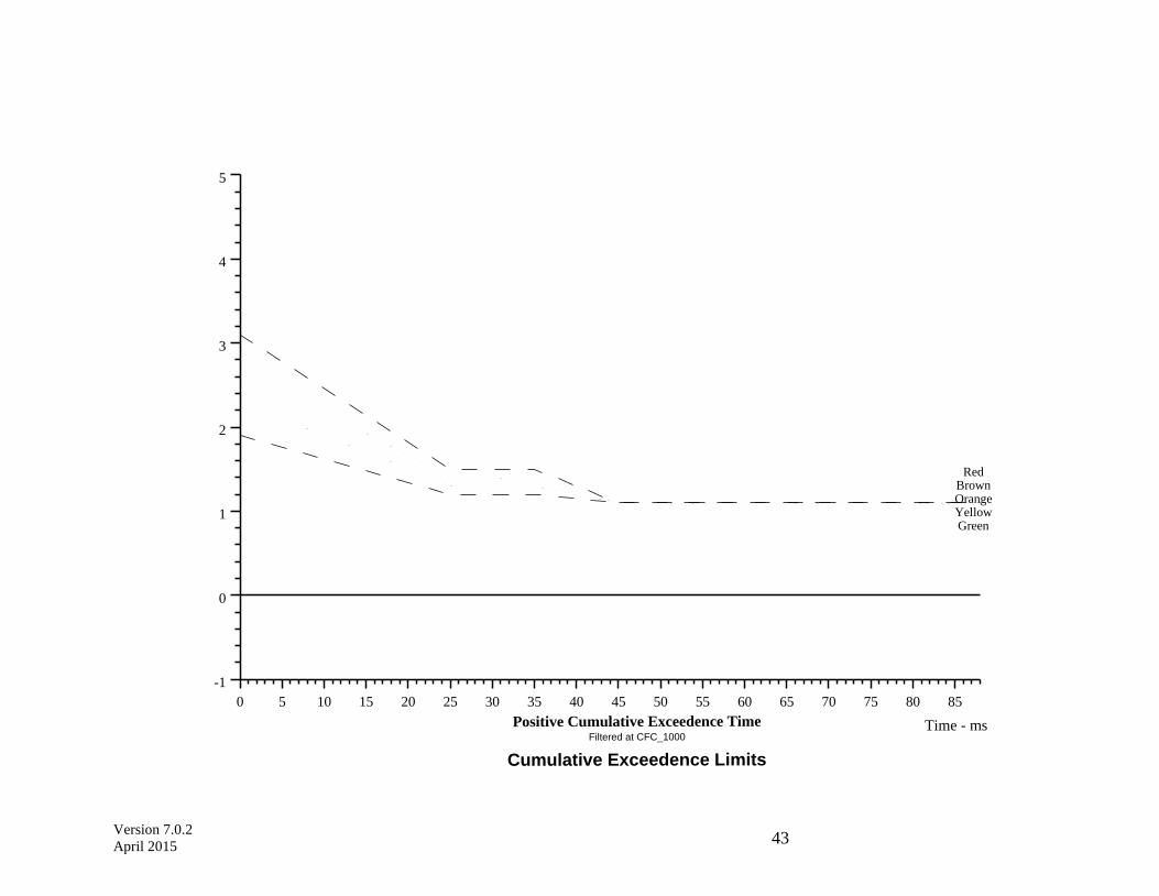
Version 7.0.2
April 2015 43
0 5 10 15 20 25 30 35 40 45 50 55 60 65 70 75 80 85
Time - ms
-1
0
1
2
3
4
5
Ex
ceed
en
ce V
alu
e:
Up
per
Neck
FX
- k
N
Cumulative Exceedence Limits
Filtered at CFC_1000
Positive Cumulative Exceedence Time
RedBrownOrangeYellowGreen

Version 7.0.2
April 2015
44
0 5 10 15 20 25 30 35 40 45 50 55 60 65 70 75 80 85
Time - ms
-5
-4
-3
-2
-1
0
1
Ex
ceed
en
ce V
alu
e:
Up
per
Neck
FX
- k
N
Cumulative Exceedence Limits
Filtered at CFC_1000
Negative Cumulative Exceedence Time
RedBrownOrangeYellowGreen

Version 7.0.2
April 2015
45
0 5 10 15 20 25 30 35 40 45 50 55 60 65 70 75 80 85
Time - ms
-1
0
1
2
3
4
5
Ex
ceed
nece V
alu
e:
Up
per
Neck
FZ
- k
N
Cumulative Exceedence Limits
Filtered at CFC_1000
Positive Cumulative Exceedence Time
Processed
on 29.01.2002
RedBrownOrangeYellowGreen
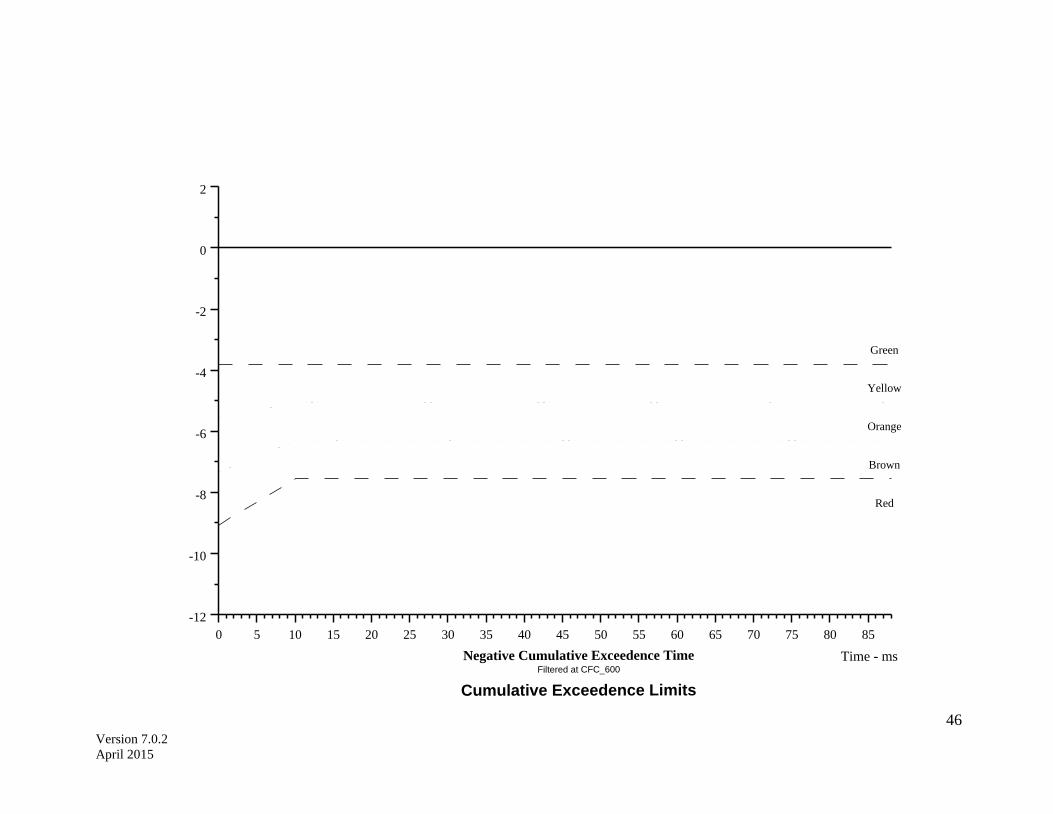
Version 7.0.2
April 2015
46
0 5 10 15 20 25 30 35 40 45 50 55 60 65 70 75 80 85
Time - ms
-12
-10
-8
-6
-4
-2
0
2
Ex
ceed
en
ce V
alu
e:
Fem
ur
- k
N
Cumulative Exceedence Limits
Filtered at CFC_600
Negative Cumulative Exceedence Time
Processed
on 01.02.2002
Red
Brown
Orange
Yellow
Green