Embed Size (px)
Citation preview
Authorisedand notified according
to Article 10 of the Council Directive 89/ 106/EEC of 21 December 1988 on the
approximation of laws, regulations and administrative provisions of Member States
relating to constructionproducts
Member of EOTAINSTITUT FÜR BAUTECHNIKÖSTERREICHISCHES
Österreichisches Institut für Bautechnik Schenkenstrasse 4 | 1010 Vienna | AustriaT +43 1 533 65 50 | F +43 1 533 64 23 [email protected] | www.oib.or.at
European Organisation for Technical ApprovalsEuropäische Organisation für Technische ZulassungenOrganisation Européenne pour l’ Agrément Technique
European technical approval ETA-13/0123(English language translation, the original version is in German language)
Handelsbezeichnung Trade name
Kabelabschottung
„System ZZ-Brandschutzsilikon NE” Cable penetration seal „System ZZ-Fire protection silicone NE “
Zulassungsinhaber Holder of approval
Karl Zimmermann Miltzstraße 29 51061 Köln Germany
Zulassungsgegenstand und Verwendungszweck
Kabelabschottung
Generic type and use of construction product
Cable penetration seal
Geltungsdauer vom Validity from
28.06.2013
bis to
27.06.2018
Herstellwerk Manufacturing plant
Karl Zimmermann GmbH Marconistraße 7-9 50769 Köln Germany
Diese Europäische technische Zulassung umfasst This European technical approval contains
17 Seiten inklusive 4 Anhängen 17 pages including 4 Annexes
Member of EOTAINSTITUT FÜR BAUTECHNIKÖSTERREICHISCHES
Page 2 of the European technical approval ETA-13/0123, with validity from 28.06.2013 to 27.06.2018
OIB-290-026/11-011
I LEGAL BASES AND GENERAL CONDITIONS
1 This European technical approval is issued by the Österreichisches Institut für Bautechnik in accordance with:
Council Directive 89/106/EEC of 21 December 1988 on the approximation of laws, regulations and administrative provisions of Member States relating to construction products1, modified by the Council Directive 93/68/EEC2
and Regulation (EC) no. 1882/2003 of the European Parliament and of the Council3;
Wiener Bauprodukte- und Akkreditierungsgesetz – WBAG. LGBl. Nr. 30/1996, zuletzt geändert durch das Gesetz LGBl. für Wien Nr. 36/2007;
Common Procedural Rules for Requesting, Preparing and the Granting of European technical approvals set out in the Annex to Commission Decision 94/23/EC4;
Guideline for European technical approval for “Fire Stopping and Fire Sealing Products - : Part 2: Penetration Seals” ETAG no. 026-Part 2, edition 2011.
2 The Österreichisches Institut für Bautechnik is authorised to check whether the provisions of this European technical approval are met. Checking may take place in the manufacturing plant. Nevertheless, the responsibility for the conformity of the products to the European technical approval and for their fitness for the intended use remains with the holder of the European technical approval.
3 This European technical approval is not to be transferred to manufacturers or agents of manufacturer other than those indicated on page 1; or manufacturing plants other than those laid down in the context of this European technical approval.
4 This European technical approval may be withdrawn by the Österreichisches Institut für Bautechnik, in particular pursuant to information by the Commission according to Article 5(1) of Council Directive 89/106/EEC.
5 Reproduction of this European technical approval including transmission by electronic means shall be in full. However, partial reproduction can be made with the written consent of the Österreichisches Institut für Bautechnik. In this case, partial reproduction has to be designated as such. Texts and drawings of advertising brochures shall not contradict or misuse the European technical approval.
6 The European technical approval is issued by the approval body in its official language. This version corresponds fully to the version circulated within EOTA. Translations into other languages have to be designated as such.
1 Official Journal of the European Communities no. L 40, 11.2.1989, p. 12 2 Official Journal of the European Communities no. L 220, 30.8.1993, p. 1 3 Official Journal of the European Union no. L 284, 31.10.2003, p. 1 4 Official Journal of the European Communities no. L 17, 20.1.1994, p. 34
Member of EOTAINSTITUT FÜR BAUTECHNIKÖSTERREICHISCHES
Page 3 of the European technical approval ETA-13/0123, with validity from 28.06.2013 to 27.06.2018
OIB-290-026/11-011
II SPECIFIC CONDITIONS OF THE EUROPEAN TECHNICAL APPROVAL
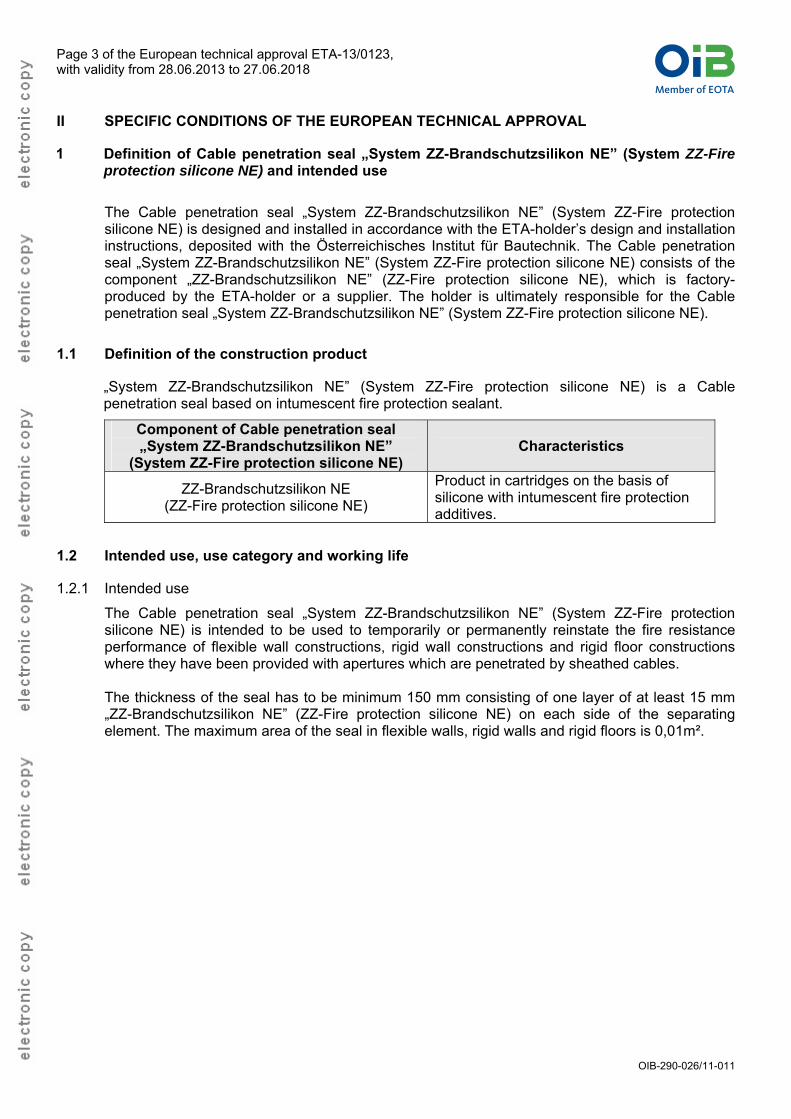
1 Definition of Cable penetration seal „System ZZ-Brandschutzsilikon NE” (System ZZ-Fire protection silicone NE) and intended use
The Cable penetration seal „System ZZ-Brandschutzsilikon NE” (System ZZ-Fire protection silicone NE) is designed and installed in accordance with the ETA-holder’s design and installation instructions, deposited with the Österreichisches Institut für Bautechnik. The Cable penetration seal „System ZZ-Brandschutzsilikon NE” (System ZZ-Fire protection silicone NE) consists of the component „ZZ-Brandschutzsilikon NE” (ZZ-Fire protection silicone NE), which is factory-produced by the ETA-holder or a supplier. The holder is ultimately responsible for the Cable penetration seal „System ZZ-Brandschutzsilikon NE” (System ZZ-Fire protection silicone NE).
1.1 Definition of the construction product
„System ZZ-Brandschutzsilikon NE” (System ZZ-Fire protection silicone NE) is a Cable penetration seal based on intumescent fire protection sealant.
Component of Cable penetration seal „System ZZ-Brandschutzsilikon NE”
(System ZZ-Fire protection silicone NE) Characteristics
ZZ-Brandschutzsilikon NE (ZZ-Fire protection silicone NE)
Product in cartridges on the basis of silicone with intumescent fire protection additives.
1.2 Intended use, use category and working life
1.2.1 Intended use
The Cable penetration seal „System ZZ-Brandschutzsilikon NE” (System ZZ-Fire protection silicone NE) is intended to be used to temporarily or permanently reinstate the fire resistance performance of flexible wall constructions, rigid wall constructions and rigid floor constructions where they have been provided with apertures which are penetrated by sheathed cables.
The thickness of the seal has to be minimum 150 mm consisting of one layer of at least 15 mm „ZZ-Brandschutzsilikon NE” (ZZ-Fire protection silicone NE) on each side of the separating element. The maximum area of the seal in flexible walls, rigid walls and rigid floors is 0,01m².
Member of EOTAINSTITUT FÜR BAUTECHNIKÖSTERREICHISCHES
Page 4 of the European technical approval ETA-13/0123, with validity from 28.06.2013 to 27.06.2018
OIB-290-026/11-011
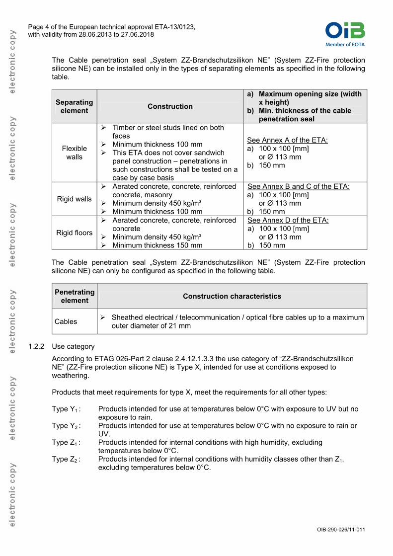
The Cable penetration seal „System ZZ-Brandschutzsilikon NE” (System ZZ-Fire protection silicone NE) can be installed only in the types of separating elements as specified in the following table.
Separating element
Construction
a) Maximum opening size (width x height)
b) Min. thickness of the cable penetration seal
Flexible walls
Timber or steel studs lined on both faces
Minimum thickness 100 mm This ETA does not cover sandwich
panel construction – penetrations in such constructions shall be tested on a case by case basis
See Annex A of the ETA: a) 100 x 100 [mm]
or Ø 113 mm b) 150 mm
Rigid walls
Aerated concrete, concrete, reinforced concrete, masonry
Minimum density 450 kg/m³ Minimum thickness 100 mm
See Annex B and C of the ETA: a) 100 x 100 [mm]
or Ø 113 mm b) 150 mm
Rigid floors
Aerated concrete, concrete, reinforced concrete
Minimum density 450 kg/m³ Minimum thickness 150 mm
See Annex D of the ETA: a) 100 x 100 [mm]
or Ø 113 mm b) 150 mm
The Cable penetration seal „System ZZ-Brandschutzsilikon NE” (System ZZ-Fire protection silicone NE) can only be configured as specified in the following table.
Penetrating element
Construction characteristics
Cables Sheathed electrical / telecommunication / optical fibre cables up to a maximum
outer diameter of 21 mm
1.2.2 Use category
According to ETAG 026-Part 2 clause 2.4.12.1.3.3 the use category of “ZZ-Brandschutzsilikon NE” (ZZ-Fire protection silicone NE) is Type X, intended for use at conditions exposed to weathering. Products that meet requirements for type X, meet the requirements for all other types: Type Y1 : Products intended for use at temperatures below 0°C with exposure to UV but no
exposure to rain. Type Y2 : Products intended for use at temperatures below 0°C with no exposure to rain or
UV. Type Z1 : Products intended for internal conditions with high humidity, excluding
temperatures below 0°C. Type Z2 : Products intended for internal conditions with humidity classes other than Z1,
excluding temperatures below 0°C.
Member of EOTAINSTITUT FÜR BAUTECHNIKÖSTERREICHISCHES
Page 5 of the European technical approval ETA-13/0123, with validity from 28.06.2013 to 27.06.2018
OIB-290-026/11-011
1.2.3 Working life
The provisions made in this ETA are based on an assumed intended working life of the product for the intended use of 10 years, provided that it is subject to appropriate use and maintenance. The indications given on the intended working life cannot be interpreted as a guarantee given by the producer or the approval body, but are to be used as a means for selecting the appropriate product in relation to the expected economically reasonable working life of the works. The real working life might be, in normal use conditions, considerably longer without major degradation affecting the Essential Requirements.
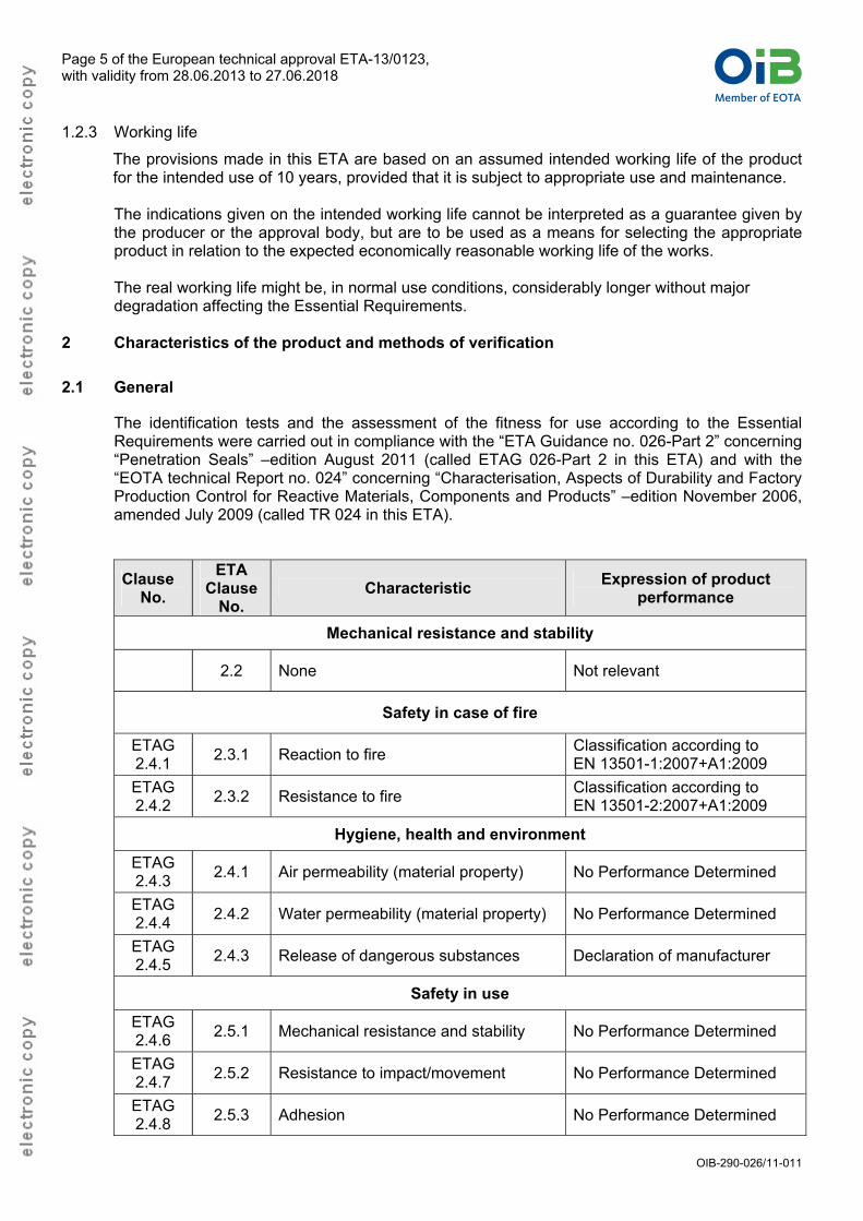
2 Characteristics of the product and methods of verification
2.1 General
The identification tests and the assessment of the fitness for use according to the Essential Requirements were carried out in compliance with the “ETA Guidance no. 026-Part 2” concerning “Penetration Seals” –edition August 2011 (called ETAG 026-Part 2 in this ETA) and with the “EOTA technical Report no. 024” concerning “Characterisation, Aspects of Durability and Factory Production Control for Reactive Materials, Components and Products” –edition November 2006, amended July 2009 (called TR 024 in this ETA).
Clause No.
ETA Clause
No. Characteristic
Expression of product performance
Mechanical resistance and stability
2.2 None Not relevant
Safety in case of fire
ETAG 2.4.1
2.3.1 Reaction to fire Classification according to EN 13501-1:2007+A1:2009
ETAG 2.4.2
2.3.2 Resistance to fire Classification according to EN 13501-2:2007+A1:2009
Hygiene, health and environment
ETAG 2.4.3
2.4.1 Air permeability (material property) No Performance Determined
ETAG 2.4.4
2.4.2 Water permeability (material property) No Performance Determined
ETAG 2.4.5
2.4.3 Release of dangerous substances Declaration of manufacturer
Safety in use
ETAG 2.4.6
2.5.1 Mechanical resistance and stability No Performance Determined
ETAG 2.4.7
2.5.2 Resistance to impact/movement No Performance Determined
ETAG 2.4.8
2.5.3 Adhesion No Performance Determined
Member of EOTAINSTITUT FÜR BAUTECHNIKÖSTERREICHISCHES
Page 6 of the European technical approval ETA-13/0123, with validity from 28.06.2013 to 27.06.2018
OIB-290-026/11-011
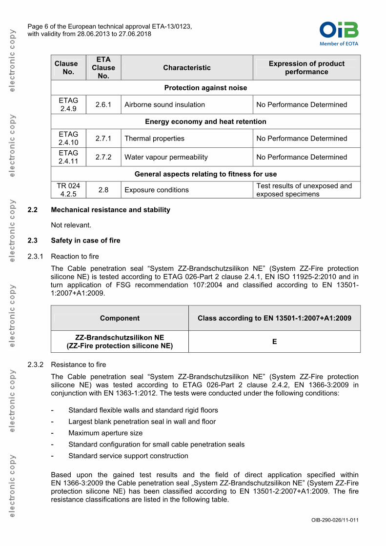
Clause No.
ETA Clause
No. Characteristic
Expression of product performance
Protection against noise
ETAG 2.4.9
2.6.1 Airborne sound insulation No Performance Determined
Energy economy and heat retention
ETAG 2.4.10
2.7.1 Thermal properties No Performance Determined
ETAG 2.4.11
2.7.2 Water vapour permeability No Performance Determined
General aspects relating to fitness for use
TR 024 4.2.5
2.8 Exposure conditions Test results of unexposed and exposed specimens
2.2 Mechanical resistance and stability
Not relevant.
2.3 Safety in case of fire
2.3.1 Reaction to fire
The Cable penetration seal “System ZZ-Brandschutzsilikon NE” (System ZZ-Fire protection silicone NE) is tested according to ETAG 026-Part 2 clause 2.4.1, EN ISO 11925-2:2010 and in turn application of FSG recommendation 107:2004 and classified according to EN 13501-1:2007+A1:2009.
Component Class according to EN 13501-1:2007+A1:2009
ZZ-Brandschutzsilikon NE (ZZ-Fire protection silicone NE)
E
2.3.2 Resistance to fire
The Cable penetration seal “System ZZ-Brandschutzsilikon NE” (System ZZ-Fire protection silicone NE) was tested according to ETAG 026-Part 2 clause 2.4.2, EN 1366-3:2009 in conjunction with EN 1363-1:2012. The tests were conducted under the following conditions: - Standard flexible walls and standard rigid floors
- Largest blank penetration seal in wall and floor
- Maximum aperture size
- Standard configuration for small cable penetration seals
- Standard service support construction
Based upon the gained test results and the field of direct application specified within EN 1366-3:2009 the Cable penetration seal „System ZZ-Brandschutzsilikon NE” (System ZZ-Fire protection silicone NE) has been classified according to EN 13501-2:2007+A1:2009. The fire resistance classifications are listed in the following table.
Member of EOTAINSTITUT FÜR BAUTECHNIKÖSTERREICHISCHES
Page 7 of the European technical approval ETA-13/0123, with validity from 28.06.2013 to 27.06.2018
OIB-290-026/11-011
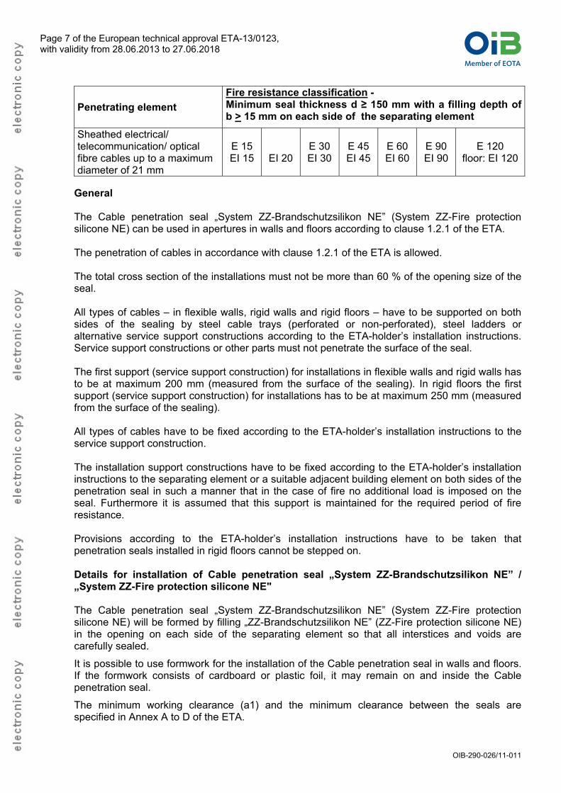
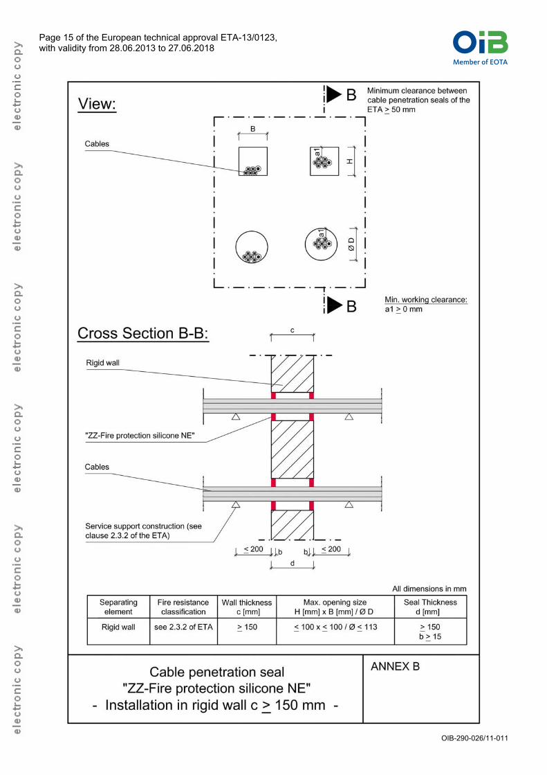
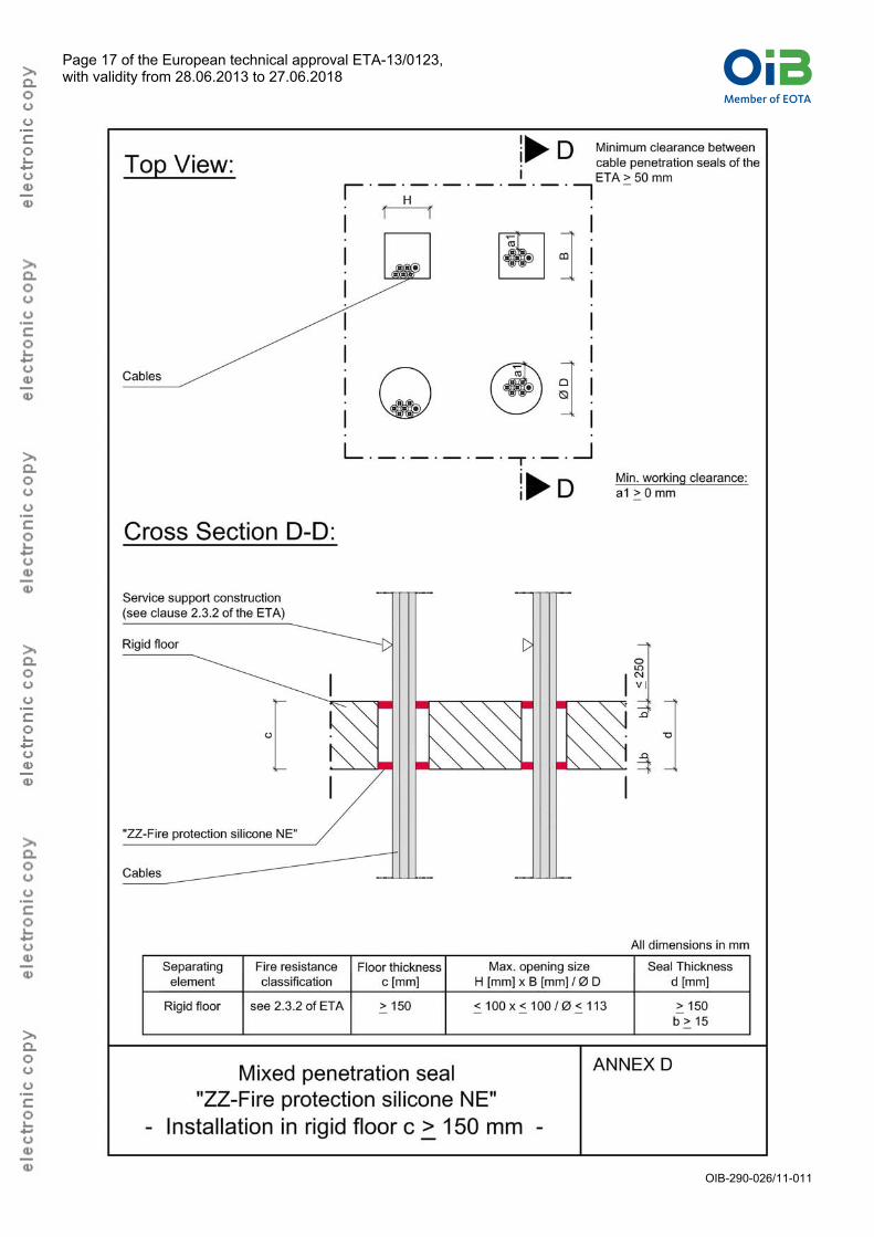
General The Cable penetration seal „System ZZ-Brandschutzsilikon NE” (System ZZ-Fire protection silicone NE) can be used in apertures in walls and floors according to clause 1.2.1 of the ETA. The penetration of cables in accordance with clause 1.2.1 of the ETA is allowed. The total cross section of the installations must not be more than 60 % of the opening size of the seal. All types of cables – in flexible walls, rigid walls and rigid floors – have to be supported on both sides of the sealing by steel cable trays (perforated or non-perforated), steel ladders or alternative service support constructions according to the ETA-holder’s installation instructions. Service support constructions or other parts must not penetrate the surface of the seal. The first support (service support construction) for installations in flexible walls and rigid walls has to be at maximum 200 mm (measured from the surface of the sealing). In rigid floors the first support (service support construction) for installations has to be at maximum 250 mm (measured from the surface of the sealing). All types of cables have to be fixed according to the ETA-holder’s installation instructions to the service support construction. The installation support constructions have to be fixed according to the ETA-holder’s installation instructions to the separating element or a suitable adjacent building element on both sides of the penetration seal in such a manner that in the case of fire no additional load is imposed on the seal. Furthermore it is assumed that this support is maintained for the required period of fire resistance. Provisions according to the ETA-holder’s installation instructions have to be taken that penetration seals installed in rigid floors cannot be stepped on. Details for installation of Cable penetration seal „System ZZ-Brandschutzsilikon NE” / „System ZZ-Fire protection silicone NE" The Cable penetration seal „System ZZ-Brandschutzsilikon NE” (System ZZ-Fire protection silicone NE) will be formed by filling „ZZ-Brandschutzsilikon NE” (ZZ-Fire protection silicone NE) in the opening on each side of the separating element so that all interstices and voids are carefully sealed.
It is possible to use formwork for the installation of the Cable penetration seal in walls and floors. If the formwork consists of cardboard or plastic foil, it may remain on and inside the Cable penetration seal.
The minimum working clearance (a1) and the minimum clearance between the seals are specified in Annex A to D of the ETA.
Penetrating element
Fire resistance classification - Minimum seal thickness d ≥ 150 mm with a filling depth of b > 15 mm on each side of the separating element
Sheathed electrical/ telecommunication/ optical fibre cables up to a maximum diameter of 21 mm
E 15 EI 15
EI 20
E 30 EI 30
E 45 EI 45
E 60 EI 60
E 90 EI 90
E 120 floor: EI 120
Member of EOTAINSTITUT FÜR BAUTECHNIKÖSTERREICHISCHES
Page 8 of the European technical approval ETA-13/0123, with validity from 28.06.2013 to 27.06.2018
OIB-290-026/11-011
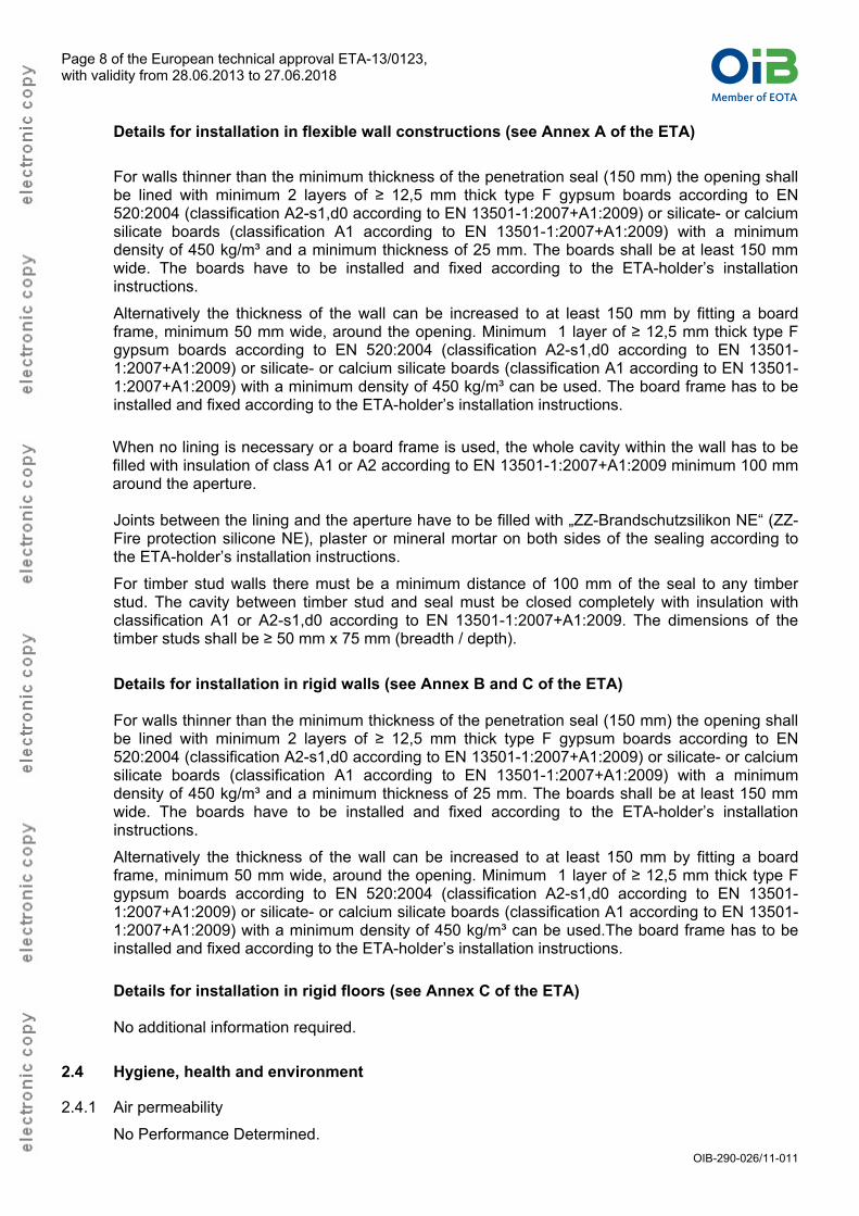
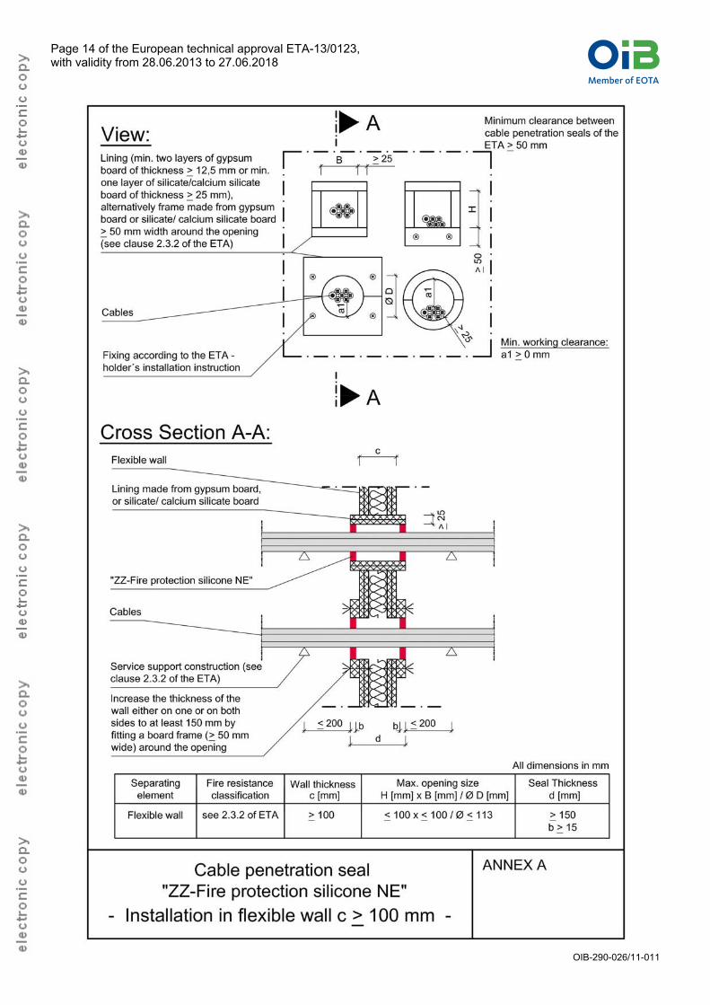
Details for installation in flexible wall constructions (see Annex A of the ETA)
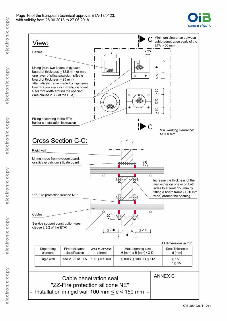
For walls thinner than the minimum thickness of the penetration seal (150 mm) the opening shall be lined with minimum 2 layers of ≥ 12,5 mm thick type F gypsum boards according to EN 520:2004 (classification A2-s1,d0 according to EN 13501-1:2007+A1:2009) or silicate- or calcium silicate boards (classification A1 according to EN 13501-1:2007+A1:2009) with a minimum density of 450 kg/m³ and a minimum thickness of 25 mm. The boards shall be at least 150 mm wide. The boards have to be installed and fixed according to the ETA-holder’s installation instructions.
Alternatively the thickness of the wall can be increased to at least 150 mm by fitting a board frame, minimum 50 mm wide, around the opening. Minimum 1 layer of ≥ 12,5 mm thick type F gypsum boards according to EN 520:2004 (classification A2-s1,d0 according to EN 13501-1:2007+A1:2009) or silicate- or calcium silicate boards (classification A1 according to EN 13501-1:2007+A1:2009) with a minimum density of 450 kg/m³ can be used. The board frame has to be installed and fixed according to the ETA-holder’s installation instructions.
When no lining is necessary or a board frame is used, the whole cavity within the wall has to be filled with insulation of class A1 or A2 according to EN 13501-1:2007+A1:2009 minimum 100 mm around the aperture.
Joints between the lining and the aperture have to be filled with „ZZ-Brandschutzsilikon NE“ (ZZ-Fire protection silicone NE), plaster or mineral mortar on both sides of the sealing according to the ETA-holder’s installation instructions.
For timber stud walls there must be a minimum distance of 100 mm of the seal to any timber stud. The cavity between timber stud and seal must be closed completely with insulation with classification A1 or A2-s1,d0 according to EN 13501-1:2007+A1:2009. The dimensions of the timber studs shall be ≥ 50 mm x 75 mm (breadth / depth).
Details for installation in rigid walls (see Annex B and C of the ETA) For walls thinner than the minimum thickness of the penetration seal (150 mm) the opening shall be lined with minimum 2 layers of ≥ 12,5 mm thick type F gypsum boards according to EN 520:2004 (classification A2-s1,d0 according to EN 13501-1:2007+A1:2009) or silicate- or calcium silicate boards (classification A1 according to EN 13501-1:2007+A1:2009) with a minimum density of 450 kg/m³ and a minimum thickness of 25 mm. The boards shall be at least 150 mm wide. The boards have to be installed and fixed according to the ETA-holder’s installation instructions.
Alternatively the thickness of the wall can be increased to at least 150 mm by fitting a board frame, minimum 50 mm wide, around the opening. Minimum 1 layer of ≥ 12,5 mm thick type F gypsum boards according to EN 520:2004 (classification A2-s1,d0 according to EN 13501-1:2007+A1:2009) or silicate- or calcium silicate boards (classification A1 according to EN 13501-1:2007+A1:2009) with a minimum density of 450 kg/m³ can be used.The board frame has to be installed and fixed according to the ETA-holder’s installation instructions.
Details for installation in rigid floors (see Annex C of the ETA) No additional information required.
2.4 Hygiene, health and environment
2.4.1 Air permeability
No Performance Determined.
Member of EOTAINSTITUT FÜR BAUTECHNIKÖSTERREICHISCHES
Page 9 of the European technical approval ETA-13/0123, with validity from 28.06.2013 to 27.06.2018
OIB-290-026/11-011
2.4.2 Water permeability
No Performance Determined.
2.4.3 Release of dangerous substances
According to the manufacturer’s declaration, the product specification has been compared with the list of dangerous substances of the European Commission to verify that it does not contain such substances above the acceptable limits. A written declaration in this respect was submitted by the ETA-holder. In addition to the specific clauses relating to dangerous substances contained in this ETA, there may be other requirements applicable to the products falling within its scope (e.g. transposed European legislation and national laws, regulations and administrative provisions). In order to meet the provisions of the Construction Products Directive, these requirements need also to be complied with, when and where they apply.
2.5 Safety in use
2.5.1 Mechanical resistance of stability
No Performance Determined.
2.5.2 Resistance to impact/movement
No Performance Determined.
2.5.3 Adhesion
No Performance Determined.
2.6 Protection against noise
2.6.1 Airborne sound insulation
No Performance Determined.
2.7 Energy economy and heat retention
2.7.1 Thermal properties
No Performance Determined.
2.7.2 Water vapour permeability
No Performance Determined.
2.8 General aspects relating to fitness for use
The Cable penetration seal „System ZZ-Brandschutzsilikon NE” (System ZZ-Fire protection silicone NE) was tested according to ETAG 026-Part 2 clause 2.4.12. The Cable penetration seal „System ZZ-Brandschutzsilikon NE” (System ZZ-Fire protection silicone NE) fulfil the requirements for the intended use category. According to ETAG 026-Part 2 clause 2.4.12.1.3.3 the use category of “ZZ-Brandschutzsilikon NE” (ZZ-Fire protection silicone NE) is Type X, intended for use at conditions exposed to weathering.
Member of EOTAINSTITUT FÜR BAUTECHNIKÖSTERREICHISCHES
Page 10 of the European technical approval ETA-13/0123, with validity from 28.06.2013 to 27.06.2018
OIB-290-026/11-011
3 Evaluation of Conformity and CE Marking
3.1 Attestation of Conformity system
According to the Decision 1999/454/EC of the European Commission5 system 1 of the attestation
of conformity applies for fire-resistance-performance. This system of attestation of conformity is to be described in the following:
System 1: Certification of the conformity of the product by a Notified Certification Body on the basis of:
a) Tasks of the manufacturer
1) Factory Production Control
2) Further testing of samples taken at the factory in accordance with a prescribed control plan
b) Tasks of the Notified Body
3) Initial type-testing of the product
4) Initial inspection of factory and of factory production control
5) Continuous surveillance, assessment and approval of factory production control
Additionally according to the Decision 2001/596/EC of the European Commission6 system 3 of
the attestation of conformity is to be used in relation to the reaction-to-fire performance. This system of attestation of conformity is to be described in the following:
System 3: Declaration of conformity of the product by the manufacturer:
a) Tasks of the manufacturer
1) Factory Production Control
b) Tasks of the Notified Body
2) Initial type-testing of the product
3.2 Responsibilities
3.2.1 Tasks of the manufacturer
3.2.1.1 Factory production control
The manufacturer shall exercise permanent internal control of production. All the elements, requirements and provisions adopted by the manufacturer shall be documented in a systematic manner in the form of written policies and procedures, including records of results performed. This production control system shall insure that the product is in conformity with this European technical approval.
The manufacturer shall draw up and keep up-to-date documents defining the factory production control that applies. The documentation to be carried out by the manufacturer and the applicable procedures shall be appropriate to the product and manufacturing process. The factory production control shall ensure the conformity of the product to an appropriate level. This involves:
a) the preparation of documented procedures and instructions relating to factory production control operations.
b) the effective implementation of these procedures and instructions.
5
Official Journal of the European Communities no. L 178, 14.7.1999, p. 52 6
Official Journal of the European Communities no. L 209, 2.8.2001, p. 33
Member of EOTAINSTITUT FÜR BAUTECHNIKÖSTERREICHISCHES
Page 11 of the European technical approval ETA-13/0123, with validity from 28.06.2013 to 27.06.2018
OIB-290-026/11-011
c) the recording of these procedures and their results.
d) the use of these results to correct any deviations, repair the effects of such deviations, treat any resulting instances of non-conformity and, if necessary, revise the factory production control to rectify the cause of non-conformity.
e) a procedure to ensure that both the approval Body and the Notified (Certification) Bodies are advised before any significant change to the product, its components or manufacturing process, is made.
f) a procedure to ensure that personnel involved in the production processes and the quality control procedures are qualified and adequately trained to carry out their required tasks.
g) that all testing and measuring equipment is maintained and up to date calibration records are documented.
h) maintenance of records to ensure every batch produced is clearly labelled with the batch number, which allows traceability to its production to be identified.
The manufacturer may only use components stated in the technical documentation of this European technical approval.
For the components which the ETA-holder does not manufacture by himself, he shall make sure that factory production control carried out by the other manufacturers gives the guaranty of the components compliance with the European technical approval.
The factory production control and the provisions taken by the ETA-holder for components not
produced by himself shall be in accordance with the control plan7 relating to this European
technical approval which is part of the technical documentation of this European technical approval. The control plan is laid down in the context of the factory production control system operated by the manufacturer and deposited at the Österreichisches Institut für Bautechnik.
The results of factory production control shall be recorded and evaluated in accordance with the provisions of the control plan.
3.2.1.2 Other tasks of the manufacturer
The manufacturer shall provide a technical data sheet and an installation instruction with the following minimum information:
technical data sheet:
a) Field of application:
1) Building elements for which the penetration seal is suitable, type and properties of the building elements like minimum thickness, density, and – in case of lightweight constructions – the construction requirements.
2) Services for which the penetration seal is suitable, type and properties of the services like material, diameter, thickness etc. in case of pipes including insulation materials; necessary/allowed supports/fixings (e.g. cable trays).
3) Limits in size, minimum thickness etc. of the penetration seal.
b) Construction of the penetration seal including the necessary components and additional products (e.g. backfilling material) with clear indication whether they are generic or specific.
Installation instruction:
a) Steps to be followed.
b) Procedure in case of retrofitting.
The manufacturer shall, on the basis of a contract, involve a body (bodies) which is (are) notified for the tasks referred to in section 3.1 in the field of approval product in order to undertake the actions laid down in section 3.3. For this purpose, the control plan
referred to in sections 3.2.1.1
7
The control plan is a confidential part of the European technical approval and only handed over to the Notified Body or Bodies involved in the procedure of conformity.
Member of EOTAINSTITUT FÜR BAUTECHNIKÖSTERREICHISCHES
Page 12 of the European technical approval ETA-13/0123, with validity from 28.06.2013 to 27.06.2018
OIB-290-026/11-011
and 3.2.2 shall be handed over by the manufacturer to the Notified Body or Bodies involved.
The manufacturer shall make a declaration of conformity, stating that the construction product is in conformity with the provisions of this European technical approval
3.2.2 Tasks of the Notified Bodies
The Notified Body (Bodies) shall perform the:
initial type-testing of the product The results of the tests performed as part of the assessment for the European technical approval can be used unless there are changes in the production line or plant. In such cases, the necessary initial type testing has to be agreed between the Österreichisches Institut für Bautechnik and the Notified Bodies involved.
initial inspection of factory and of factory production control The Notified Body (Bodies) shall ascertain that, in accordance with the control plan, the factory (in particular the employees and the equipment) and the factory production control are suitable to ensure continuous and orderly manufacturing of the components according to the specifications mentioned in clause 2 of this ETA.
continuous surveillance, assessment and approval of factory production control The Notified Body (Bodies) shall visit the factory at least once a year for surveillance of this manufacturer having a FPC system complying with a quality management system covering the manufacturing of the approval product components. It has to be verified that the system of factory production control and the specified automated manufacturing process are maintained taking into account the control plan
These tasks shall be performed in accordance with the provisions laid down in the control plan of
this European technical approval.
The Notified Body (Bodies) shall retain the essential points of its (their) actions referred to above and state the results obtained and conclusions drawn in written report.
In the case of Attestation of Conformity system 1: The Notified Body involved by the manufacturer shall issue an EC certificate of conformity of the product stating the conformity with the provisions of this European technical approval.
In cases where the provisions of the European technical approval and its control plan are no longer fulfilled, the Certification Body shall withdraw the certificate of conformity and inform the Österreichisches Institut für Bautechnik without delay.
3.3 CE marking
The CE marking shall be affixed either on the product itself, on a label attached to it, on its packaging or on the commercial documents accompanying the components of the product. The letters « CE » shall be followed by the identification number of the Notified Body involved and be accompanied by the following additional information:
- the name or identifying mark and address of the ETA-holder
- the last two digits of the year in which the CE marking was affixed
- the number of the EC certificate of conformity for the product
- the number of the European technical approval
- the number of the ETAG (ETAG N° 026 part 2)
- the designation of the product (trade name)
- the use category in accordance with the ETA section 1 and 2
- for other relevant characteristics (e.g. resistance to fire) see ETA-13/0123
Member of EOTAINSTITUT FÜR BAUTECHNIKÖSTERREICHISCHES
Page 13 of the European technical approval ETA-13/0123, with validity from 28.06.2013 to 27.06.2018
OIB-290-026/11-011
4 Assumptions under which the fitness of the product for the intended use was favourably assessed
4.1 Manufacturing
The European technical approval is issued for the product on the basis of agreed data/information, deposited with the Österreichisches Institut für Bautechnik, which identifies the product that has been assessed and judged. Changes to the product or production process, which could result in this deposited data/information being incorrect, should be notified to the Österreichisches Institut für Bautechnik before the changes are introduced. The Österreichisches Institut für Bautechnik will decide whether or not such changes affect the ETA and consequently the validity of the CE marking on the basis of the ETA and if so whether further assessment or alterations to the ETA, shall be necessary.
4.2 Installation
The ETA is issued under the assumption that the installation of the approval product shall be in accordance with the manufacturer’s technical literature.
5 Indications to the manufacturers
5.1 Packaging, transport and storage
In the accompanying document and/or on the packaging the manufacturer shall give information as to transport and storage.
At least the following shall be indicated: storing temperature, maximum duration of storage and required data related to minimum temperature for transport and storage.
5.2 Use, maintenance and repair
The product shall be installed and used as described in this ETA.
The assessment of the fitness for use is based on the assumption that necessary maintenance and repair if required is carried out in accordance with the manufacturer’s instructions during the assumed intended working life.
On behalf of Österreichisches Institut für Bautechnik
The original document is signed by:
Rainer Mikulits Managing Director
Member of EOTAINSTITUT FÜR BAUTECHNIKÖSTERREICHISCHES
Page 14 of the European technical approval ETA-13/0123, with validity from 28.06.2013 to 27.06.2018
OIB-290-026/11-011
Member of EOTAINSTITUT FÜR BAUTECHNIKÖSTERREICHISCHES
Page 15 of the European technical approval ETA-13/0123, with validity from 28.06.2013 to 27.06.2018
OIB-290-026/11-011
Member of EOTAINSTITUT FÜR BAUTECHNIKÖSTERREICHISCHES
Page 16 of the European technical approval ETA-13/0123, with validity from 28.06.2013 to 27.06.2018
OIB-290-026/11-011
Member of EOTAINSTITUT FÜR BAUTECHNIKÖSTERREICHISCHES
Page 17 of the European technical approval ETA-13/0123, with validity from 28.06.2013 to 27.06.2018
OIB-290-026/11-011


![28.06.2013. - Lipovica d.o.o., Popovača [PDF 3.23 MB]](https://img.pdfslide.net/doc/110x75/589c48681a28ab814a8b6810/28062013-lipovica-doo-popovaca-pdf-323-mb.jpg)