Embed Size (px)
Citation preview
ETA-Danmark A/S Göteborg Plads 1 DK-2150 Nordhavn Tel. +45 72 24 59 00 Fax +45 72 24 59 04 Internet www.etadanmark.dk
Authorised and notified according to Article 29 of the Regulation (EU) No 305/2011 of the European Parliament and of the Council of 9 March 2011
MEMBER OF EOTA
European Technical Assessment ETA-07/0285 of 2018/06/12
I General Part
Technical Assessment Body issuing the ETA and designated according to Article 29 of the Regulation (EU) No 305/2011: ETA-Danmark A/S
Trade name of the construction product:
Simpson Strong-Tie Hold Downs & Post Bases
Product family to which the above construction product belongs:
Three-dimensional nailing plate (timber to timber and timber to concrete/steel hold downs and post bases)
Manufacturer: SIMPSON STRONG-TIE Int. Ltd For local branch refer to www.strongtie.eu
Manufacturing plant:
SIMPSON STRONG-TIE Manufacturing facilities
This European Technical Assessment contains:
149 pages including 4 annexes which form an integral part of the document
This European Technical Assessment is issued in accordance with Regulation (EU) No 305/2011, on the basis of:
Guideline for European Technical Approval (ETAG) No. 015 Three Dimensional Nailing Plates, April 2013, used as European Assessment Document (EAD).
This version replaces:
The ETA with the same number and issued on 2015-12-03
Page 2 of 149 of European Technical Assessment no. ETA-07/0285 issued on 2018-06-12
INDEX
II SPECIFIC PART OF THE EUROPEAN TECHNICAL ASSESSMENT .................................................. 5
1 TECHNICAL DESCRIPTION OF PRODUCT AND INTENDED USE .................................................................................. 5 2 SPECIFICATION OF THE INTENDED USE IN ACCORDANCE WITH THE APPLICABLE EAD .......................................... 5 3 PERFORMANCE OF THE PRODUCT AND REFERENCES TO THE METHODS USED FOR ITS ASSESSMENT ...................... 7
3.1 Mechanical resistance and stability*) (BWR1) ............................................................................................... 7 3.2 Safety in case of fire (BWR2) ........................................................................................................................... 7 3.3 Hygiene, health and the environment (BWR3) ................................................................................................ 7 3.7 Sustainable use of natural resources (BWR7) ................................................................................................. 7 3.8 General aspects related to the performance of the product .......................................................................... 7 3.9 Safety principles and partial factors .................................................................................................................... 8 3.10 Mechanical resistance and stability ................................................................................................................... 8 3.11 Aspects related to the performance of the product ............................................................................................. 9 3.12 General aspects related to the fitness for use of the product ....................................................................... 9
4 ATTESTATION AND VERIFICATION OF CONSTANCY OF PERFORMANCE (AVCP) .................................................. 11 4.1 AVCP system ................................................................................................................................................. 11
5 TECHNICAL DETAILS NECESSARY FOR THE IMPLEMENTATION OF THE AVCP SYSTEM, AS FORESEEN IN THE
APPLICABLE EAD ......................................................................................................................................................... 11
ANNEX A: REVISION HISTORY ............................................................................................................... 12
TABLE WITH THE PRODUCT NAMES AND ALTERNATIVE NAMES .................................................................................. 14
ANNEX B TYPICAL INSTALLATION ........................................................................................................ 15
B1 TYPICAL INSTALLATION POST BASES ...................................................................................................................... 15 B2 TYPICAL INSTALLATION OF STEEL COLUMN ........................................................................................................... 16
ANNEX C BASIS OF DESIGN ................................................................................................................... 18
C0 SYMBOLS USED IN THE ETA-07/0285 ..................................................................................................................... 18 C1 DESIGN BASIS - GENERAL ....................................................................................................................................... 18 C2 DEFINITION OF FORCE DIRECTIONS......................................................................................................................... 20
C2a Force directions for post bases ......................................................................................................................... 20 C2b Forces directions for hold downs ..................................................................................................................... 21
C3 FASTENERS ............................................................................................................................................................. 23
ANNEX D PRODUCT DEFINITION AND CAPACITIES ............................................................................. 24
POST BASES ............................................................................................................................................ 24
D1: ABE ....................................................................................................................................................................... 24 D2: ABW ..................................................................................................................................................................... 25 D3: APB100-150 .......................................................................................................................................................... 27 D4: APB7090/100 ........................................................................................................................................................ 28 D5: APR110-150 .......................................................................................................................................................... 29 D6: CMR & CMS ......................................................................................................................................................... 30 D7: CPB & CPS ........................................................................................................................................................... 32 D8: CPT ....................................................................................................................................................................... 34 D9: FPB ........................................................................................................................................................................ 36 D10: PB3B PB3C ......................................................................................................................................................... 37 D11: PBH ..................................................................................................................................................................... 38 D12: PBLR ................................................................................................................................................................... 39 D13: PBP60 - 50 ........................................................................................................................................................... 40 D14: PBS ...................................................................................................................................................................... 41 D15: PGS ..................................................................................................................................................................... 42 D16: PI ......................................................................................................................................................................... 44 D17: PIBA .................................................................................................................................................................... 45 D18: PIL ....................................................................................................................................................................... 46 D19: PIS / PISB / PISMAXI / PISBMAXI ................................................................................................................... 47
Page 3 of 149 of European Technical Assessment no. ETA-07/0285 issued on 2018-06-12
D24: PJPS / PJPB / PJIS / PJIB ..................................................................................................................................... 49 D20: PL ........................................................................................................................................................................ 52 D21: PLPP180 .............................................................................................................................................................. 54 D22: PLS & PLB .......................................................................................................................................................... 55 D23: PP & PPL ............................................................................................................................................................. 57 D24: PPA & PBL ......................................................................................................................................................... 58 D25: PPB & PPS80 ...................................................................................................................................................... 59 D26: PPD ..................................................................................................................................................................... 60 D27: PPMINI ............................................................................................................................................................... 62 D28: PPR ...................................................................................................................................................................... 63 D29: PPRB ................................................................................................................................................................... 64 D30: PPRC ................................................................................................................................................................... 65 D31: PPRIX ................................................................................................................................................................. 66 D32: PPS & PPSDT ..................................................................................................................................................... 67 D33: PPSP .................................................................................................................................................................... 69 D34: PPSR320 ............................................................................................................................................................. 70 D35: PPUP ................................................................................................................................................................... 71 D36: PU / EMBU ......................................................................................................................................................... 72 D37: PUA ..................................................................................................................................................................... 73 D38: PVD / PVDB / PVI / PVIB .................................................................................................................................. 75 D39: TPB ..................................................................................................................................................................... 77
COLUMN ................................................................................................................................................... 79
D40: OSP & OSPS ....................................................................................................................................................... 79
HOLD DOWNS ........................................................................................................................................ 111
D60: AH ..................................................................................................................................................................... 111 D61: AKR .................................................................................................................................................................. 114 D62: BETA ................................................................................................................................................................ 125 D63: HD TENSION TIE ................................................................................................................................................ 127 D64: HD2P ................................................................................................................................................................. 130 D65: HD3B ................................................................................................................................................................ 135 D66: HD5A ................................................................................................................................................................ 136 D67: HE ..................................................................................................................................................................... 137 D68: HTT & LTT ....................................................................................................................................................... 139 D69: MAH ................................................................................................................................................................. 145 D70: PROFA .............................................................................................................................................................. 147 D71: SCMF ................................................................................................................................................................ 149

Page 4 of 149 of European Technical Assessment no. ETA-07/0285 issued on 2018-06-12
Translations of this European Technical Assessment in other languages shall fully correspond to the original issued document and should be identified as such. Communication of this European Technical Assessment, including transmission by electronic means, shall be in full (excepted the confidential Annex(es) referred to above). However, partial reproduction may be made, with the written consent of the issuing Technical Assessment Body. Any partial reproduction has to be identified as such.
Page 5 of 149 of European Technical Assessment no. ETA-07/0285 issued on 2018-06-12
II SPECIFIC PART OF THE EUROPEAN TECHNICAL ASSESSMENT
1 Technical description of product and intended use
Technical description of the product The hold downs are one or more pieces, non-welded hold downs. They are intended for timber to timber, timber to concrete or timber to steel connections fastened by a range of nails, screws or bolts. Post bases ABE, PBS and U-shoe are manufactured by pressing of galvanized steel plates. PBP60/50 is manufactured by pressing of raw steel. All other post bases are welded steel connectors. The upper part e.g. a plate, a U-shaped plate or a vertical plate for embedment into the timber is fastened to the timber member with nails, screws, bolts or dowels. The lower part of the post base is either a bar, a threaded rod, a tube or a plate for embedment into the support of concrete or a steel plate to be fastened by anchor bolts to the concrete support. Posts OSP and OSPS are steel column made of a circular hollow tube with a plate welded at each end. These plates can be selected among 8 different available plates. Steel quality, dimensions of the post bases, hole positions and corrosion protection are shown in Annex D. The post bases and hold downs can also be produced from stainless steel type 1.4401 or type 1.4404 according to EN 10088-2 or a stainless steel with a minimum characteristic yield stress of 235 N/mm² or a minimum ultimate tensile strength of 330 N/mm². Dimensions, hole positions, steel type and typical installations are shown in Annex B and D.
2 Specification of the intended use in accordance with the applicable EAD
The intended use of the post bases and the hold downs is to support timber structures or wood-based structural members to their support, where requirements for mechanical resistance and stability and safety in use in the sense of the Basic Works Requirements 1 and 4 of Regulation (EU)
305/2011 shall be fulfilled. Each connection shall be made with one post base. The static and kinematic behaviour of the timber members or the supports shall be as described in Annex D. The wood members can be of solid timber, glued laminated timber and similar glued members, or wood-based structural members with a characteristic density from 290 kg/m3 to 420 kg/m3. This requirement to the material of the wood members can be fulfilled by using the following materials:
• Solid timber classified to C14-C40 according to EN 338 / EN 14081
• Glued members of timber classified to C14-C40 according to EN 338 / EN 14081 when structural adhesives are used.
• Glued laminated timber classified to GL24c or better according to EN 1194 / EN 14080.
• Solid Wood Panels, SWP according to EN 13353.
• Laminated Veneer Lumber LVL according to EN 14374
• Plywood according to EN 636
• Oriented Strand Board, OSB according to EN 300
• Cross Laminated timber according to EN 16351
Annex C states formulas for the characteristic load-carrying capacity of the post bases and the hold down connections, which depend on the characteristic density of the timber employed. For some of the connectors Annex D states the load-carrying capacities of the post bases and the hold down connections for a characteristic density of 350 kg/m3. For timber or wood based material with a lower characteristic density than 350 kg/m3 the load-carrying capacities shall be reduced by the kdens factor:
350
k
densk
Where ρk is the characteristic density of the timber in kg/m3. For timber or wood based material with a higher characteristic density than 350 kg/m3 the load-carrying capacities shall be taken as that for 350 kg/m3 unless detailed analyses are conducted.
Page 6 of 149 of European Technical Assessment no. ETA-07/0285 issued on 2018-06-12
The post bases down-load bearing capacities are given for timber which grain is parallel to the load axis unless other grain direction is stated. The design of the connections shall be in accordance with Eurocode 5 or a similar national provision. The wood members shall have a thickness which is larger than the penetration depth of the nails into the members. The hold downs are primarily for use in timber structures subject to the dry, internal conditions defined by service class 1 and 2 of Eurocode 5 and for connections subject to static or quasi-static loading. The hold downs can also be used in outdoor timber structures, service class 3, when a corrosion protection in accordance with Eurocode 5 or coating ZM310 is applied, or when stainless steel with similar or better characteristic yield or ultimate strength is employed. The post bases with a zinc coating Z275 or ZM310 according to EN 10346 or G90 according to ASTM A-653 are intended for use in service class 1 and 2 according to EN 1995 (Eurocode 5). Post bases which are hot dipped galvanized according to EN ISO 1461:1999 with a zinc coating thickness of approximately 55 μm or made from stainless steel according to EN 10088:2005 or sherardized according to EN 13811:2003 or electroplated zinc according to EN 1403 and 12329:2000 allowing a use in external conditions are intended for use in service class 1,2 and 3 according to EN 1995 (Eurocode 5). The hold downs may also be used for connections
between a timber member and a support made from concrete blocks or similar. The provisions made in this European Technical Assessment are based on an assumed intended working life of the connectors of 50 years. The indications given on the working life cannot be interpreted as a guarantee given by the producer or Assessment Body, but are to be regarded only as a means for choosing the right products in relation to the expected economically reasonable working life of the works.
Page 7 of 149 of European Technical Assessment no. ETA-07/0285 issued on 2018-06-12
3 Performance of the product and references to the methods used for its assessment
Characteristic
Assessment of characteristic
3.1 Mechanical resistance and stability*) (BWR1)
Characteristic load-carrying capacity
See Annex D
Stiffness
No performance assessed
Ductility in cyclic testing
No performance assessed
3.2 Safety in case of fire (BWR2)
Reaction to fire
The post bases are made from steel classified as Euroclass A1 in accordance with EN 13501-1 and EC decision 96/603/EC, amended by EC Decision 2000/605/EC
3.3 Hygiene, health and the environment (BWR3)
Influence on air quality
The product does not contain/release dangerous substances specified in TR 034, dated March 2012**)
3.7 Sustainable use of natural resources (BWR7)
No Performance assessed
3.8 General aspects related to the performance of the product
The post bases have been assessed as having satisfactory durability and serviceability when used in timber structures using the timber species described in Eurocode 5 and subject to the conditions defined by service class 1, 2 and 3
Identification
See Annex A
*) See additional information in section 3.9 – 3.12. **) In addition to the specific clauses relating to dangerous substances contained in this European technical Assessment, there may be other requirements applicable to the products falling within its scope (e.g. transposed European legislation and national laws, regulations and administrative provisions). In order to meet the provisions of the Construction Products Regulation, these requirements need also to be complied with, when and where they apply.
Page 8 of 149 of European Technical Assessment no. ETA-07/0285 issued on 2018-06-12
3.9 Safety principles and partial factors The characteristic load-carrying capacities have been calculated considering different ratios between the partial factors for timber connections and steel cross sections. According to clause 6.3.5 of EN 1990 (Eurocode – Basis of structural design) the characteristic resistance for structural members that comprise more than one material acting in association should be calculated as
d
im
m
iikik
M
d aXXRR ;;1
,
1.
)1(,1,1
1,
where 1,M is the global partial factor for material 1
(in this case wood), 1,m is the partial factor on the
material and im, are material partial factors for the
other materials, i.e. the calculations are made with material parameters modified by multiplication by
kmodi = imm ,1,
The characteristic load-carrying capacities for all product except OSP have been calculated considering a ratio between the partial factor for timber connections and steel / concrete cross sections. kmodi = 1.18 for steel yield strength
(𝐸𝐶5: 𝑘𝑚𝑜𝑑𝑖.𝑦 = 1.30
1.10= 1.18)
kmodi = 1.04 for steel ultimate strength
(𝐸𝐶5: 𝑘𝑚𝑜𝑑𝑖.𝑢 = 1.30
1.25= 1.04)
87,0dimok for anchor bolt in concrete
(𝐸𝐶5: 𝑘𝑚𝑜𝑑𝑖.𝑐 = 1.30
1.5= 0.87)
For kmodi> 1.18 / 1.04 / 0.87 the load-carrying capacities stated in Annex B and D are valid (on the safe side). For kmodi<1.18 / 1.04 / 0.87 the load-carrying capacities stated in Annex B have to be multiplied by a factor
𝑘𝑠𝑎𝑓𝑒 = 𝑘𝑚𝑜𝑑𝑖.𝑦
1.18 𝑜𝑟
𝑘𝑚𝑜𝑑𝑖.𝑢1.04
𝑜𝑟 𝑘𝑚𝑜𝑑𝑖.𝑐0.87
3.10 Mechanical resistance and stability See annex D for characteristic load-carrying capacity in the different force directions F1 to F5. The characteristic capacities of the post bases and the hold downs are determined by calculation assisted by testing as described in the EOTA Guideline 015 clause 5.1.2. They should be used for designs in accordance with Eurocode 5 or a similar national Timber Code. Fastener Connector nails and screws in accordance with ETA-04/0013 The load-carrying capacities of the post bases and the hold downs have been determined based on the use of connector nails 4.0x35, 4.0x40, 4.0x50, 4.0x60 or 4.0x75 in accordance with ETA-04/0013. It is allowed to use connector screws 5.0x35, 5.0x40, 5.0x50, 5.0x80, or connector nails 4.2x35, 4.2x50 or 4.2x60 in accordance with ETA-04/0013 with the same or better performance as the 4.0 mm connector nails and still achieve the same load-carrying capacity of the connection. The capacity of a post base connection and a hold down connection with 4.0x50 connector nails in accordance with ETA-04/0013 can be calculated by linear interpolation between the capacities for 4.0x40 and 4.0x60 connector nails. Threaded nails in accordance with EN 14592 The design model also allows the use of threaded nails in accordance with EN 14592 with a diameter in the range 4.0 – 4.2 mm and a minimum length of 35 mm, assuming a thick steel plat when calculating the lateral nail load-carrying capacity. If no calculations are made a reduction factor equal to the ratio between the characteristic withdrawal capacity of the actual used threaded nail and the characteristic withdrawal capacity of the corresponding connector nail according to table B1 in ETA-04/0013 is applicable for all load-carrying capacities of the connection. Other fasteners Further, for most hold downs, anchor bolts are assumed as fasteners to a reinforced concrete structure. For such hold downs it is stated at the tables with load-carrying capacities (Annex B) which characteristic capacities have been assumed for the bolt connection. Bolts to a steel structure with at least the same capacities can also be used.
Page 9 of 149 of European Technical Assessment no. ETA-07/0285 issued on 2018-06-12
Stainless steel For the post bases and the hold downs produced from stainless steel type 1.4401 or type 1.4404 according to EN 10088-4:2005 or a stainless steel with a minimum characteristic 0.2% yield stress of 240 N/mm², a minimum 1.0% yield stress of 270 N/mm² and a minimum ultimate tensile strength of 530 N/mm² the characteristic load carrying capacities can be considered as the same as those published in this document subject to the use of stainless CNA connector nails or CSA connector screws covered by the ETA-04/0013 or stainless threaded nails or screws in accordance to the standard EN 14592 respecting the rules given in the paragraph "fasteners" above. 3.11 Aspects related to the performance of the product 3.11.1 Corrosion protection in service class 1 and 2 In accordance with ETAG 015 the hold downs shall have a zinc coating weight of min. Z275. The steel employed is S250GD (S350GD) with min. Z275 according to EN 10346 and G90 SS Grade 33 according to ASTM A-653. 3.11.2 Corrosion protection in service class 3 In accordance with Eurocode 5 the hold downs with a thickness of up to 3 mm shall be made from stainless steel. Hold downs with a thickness from 3 to 5 mm can be made from stainless steel or have a zinc coating of min. Fe/Zn 25c/Z350 according to ISO 2081/EN 10147. The nails or screws shall be produced from stainless steel or have a zinc coating of min. Fe/Zn 25c. This requirement is fulfilled by post bases with a corrosion protection hot-dip galvanized of approximately 55 μm according to EN ISO 1461:1999 or stainless steel according to EN10088:2005 or electroplated zinc coating according to EN12329:2000 allowing a use of the product in external conditions or sherardizing according to EN 13811:2003. Alternatively, ZM310 can be used as corrosion protection in service class 3 (applicable for all steel thicknesses). 3.12 General aspects related to the fitness for use of the product The post bases and the hold downs are manufactured in accordance with the provisions of the European Technical Assessment using the automated manufacturing process as identified during the inspection of the plant by notified
inspection body and laid down in the technical documentation. The execution of the connection shall be in accordance with the manufacturers installation guide. Hold downs A hold down connection is deemed fit for use provided:
• The forces shall act on the timber members as described in Annex C.
• The timber member shall be free from wane under the nails in the vertical flap.
• The support shall be restrained against rotation.
• Nail or screw types and sizes shall be those mentioned in the tables of Annex D.
• The nails or screws shall be inserted without pre-drilling of the holes.
• There shall be nails or screws in the holes as prescribed in Annex D.
• There shall be no gap between the hold down connector and the timber member or the support, unless otherwise described
• The bolts shall have a diameter not less than the hole diameter minus 2 mm.
• The bolts shall have washers as specified in Annex C
Post bases The stated type of fasteners for each post base has to be applied in applicable holes in the post base. The installation instructions provided by the manufacturer stipulate:
• The primary structural member – the post member shown in typical installation page 16 or a beam member - to which the post bases are fixed shall be:
– Restrained against rotation – Capable to transfer the force to the post
bases as assumed. – Free from wane in areas in contact with the
post base.
• The secondary structural member – the concrete support - to which the post bases are fixed shall be:
– Made from concrete of at least strength class C16/20, unless other strength class is indicated in annex C of this ETA.
• To ensure sufficient capacity the designer has to take into account splitting of the timber.
• The timber member shall be free from wane.

Page 10 of 149 of European Technical Assessment no. ETA-07/0285 issued on 2018-06-12
• The timber section sizes shall be equal or superior to the horizontal plate in contact with timber when contact is required (not appropriate for TPB).
• There shall be no gap between the timber and the horizontal contact area.
• Otherwise the gap between the timber member and the post base may not exceed 3 mm.
• There are no specific requirements relating to preparation of the timber members.
Page 11 of 149 of European Technical Assessment no. ETA-07/0285 issued on 2018-06-12
4 Attestation and verification of constancy of performance (AVCP)
4.1 AVCP system According to the decision 97/638/EC of the European Commission1, as amended, the system(s) of assessment and verification of constancy of performance (see Annex V to Regulation (EU) No 305/2011) is 2+.
5 Technical details necessary for the implementation of the AVCP system, as foreseen in the applicable EAD
Technical details necessary for the implementation of the AVCP system are laid down in the control plan deposited at ETA-Danmark prior to CE marking.
Issued in Copenhagen on 2018-06-12 by
Thomas Bruun Managing Director, ETA-Danmark

Page 12 of 149 of European Technical Assessment no. ETA-07/0285 issued on 2018-06-12
Annex A: Revision History
Modifications and additions to the previous versions of ETA-07/0285 (and ETA-07/0314 merged in v4.0)
Issue No. Update
ETA-07/0285 1.0 First release
ETA-07/0314 1.0 First release
ETA-07/0285 2.0
Update of the dimensions C for post base type D/PPD.
Update of the steel material of the tube for post bases PL, L and IL
Update of the steel thickness of the tube of PPA post bases
Add new post bases FPB, APB100/150, PBP60/50, CPB/CPS, PGS
Update of coating for PPRB, PPRC, PBLR and APB7090/100
Update of the steel material of the tube for PPRC and PBLR
Update of the dimensions E2 and E3 for PPS230
Add figures and ribbed bar diameter for PPSP post bases
Update of the steel thickness of the tube of PBL post bases
Add table 3 giving the factor to apply on characteristic values for use in service class 3
Reduction of the resistance capacities for uplift load FR2 next to the revision of the nails capacities according to the update of the ETA-04/0013 (valid from 2008-08-13 to 2013-08-13). Reduction occurs for the post bases D/PPD, L, LS, LB, vario D/PB, vario DB/PB, U-shoe, PPUP, PBS, ABE. Reduction occurs also for lateral load HR1 for PPUP for the same reasons.
Update of HR1 values for post base I next to mistakes
Reduction of the resistance capacities next to the revision of the steel properties of the tube for download FR1 for the post bases PL, L, IL and lateral load HR for PL and IL
Update of HR2 values for post base vario IB next to mistakes
Update of the resistance capacities table for download FR1 for PPR, PPRB and PPRC
Add characteristic resistance capacities for new post bases FPB, APB100/150, PBP60/50, CPB, CPS and PGS.
ETA-07/0285 3.0
Insert list with names and alternative names
Insert stainless steel
Insert PLPP180
Modification of hole size and hole position for PPRIX
Add steel quality for PPSP70 and PPSP90
Add post bases PPSR320
Add post base CMS
Modification the calculation for service class 3
Delete the size 90x60 and 100x60 in table for force direction HR1 and HR2
Modification of values F1 for PJPS;PJPB, PJIS; PJIB,
Modification of values F1 for PPSP70, PPSP90
Add type PPSP320
Add type CMS
Modification of the hole-Ø in the bottom plates for types: PISB, PISBMAXI, PLB, PVDB, PVIB, PPB, PJPB, PJIB, PPMINI, APB7090, CPB From Ø11 to 11/12mm, or from Ø13 to 13/14mm, or from Ø17 to 17/18mm
Rename the types
ETA-07/0314 3.0
Rename the index
Add the new components of HD2P
Add the characteristic capacities for the new components of HD2P
Page 13 of 149 of European Technical Assessment no. ETA-07/0285 issued on 2018-06-12
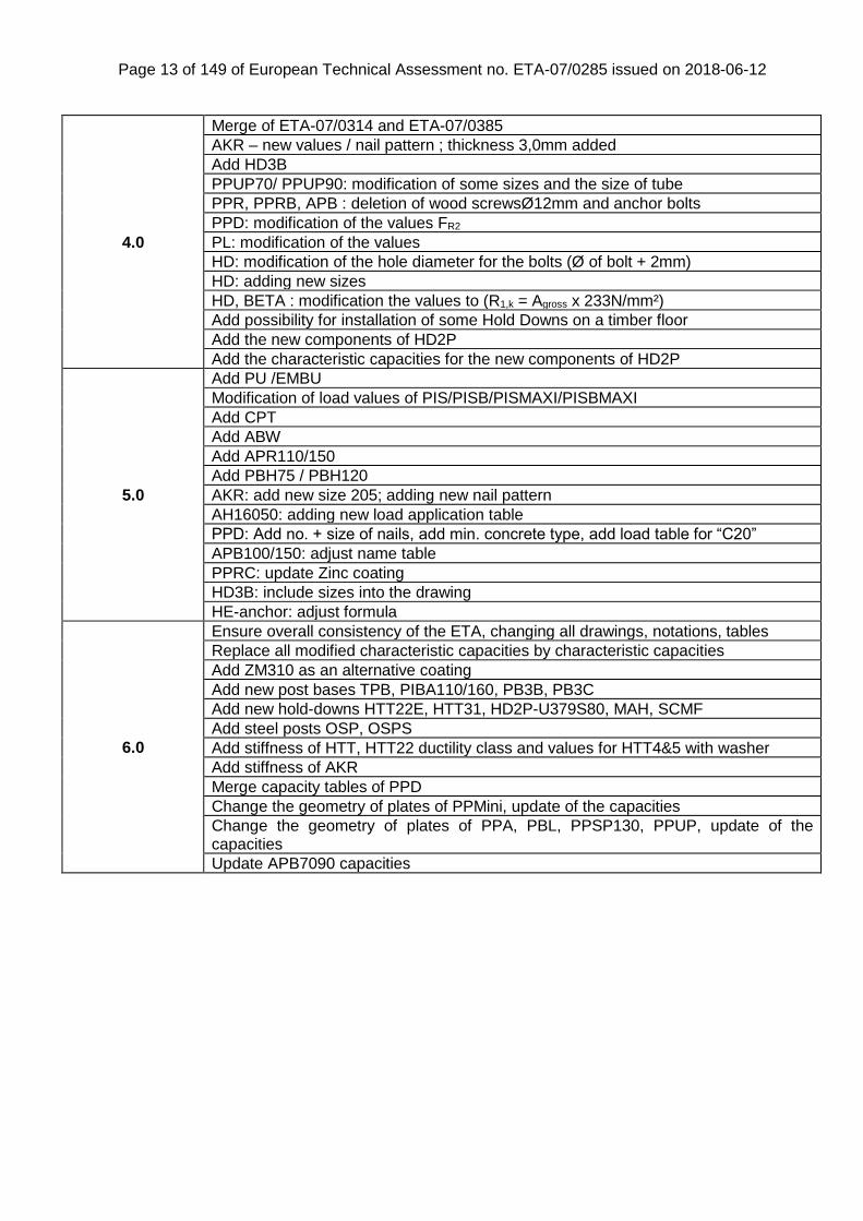
4.0
Merge of ETA-07/0314 and ETA-07/0385
AKR – new values / nail pattern ; thickness 3,0mm added
Add HD3B
PPUP70/ PPUP90: modification of some sizes and the size of tube
PPR, PPRB, APB : deletion of wood screwsØ12mm and anchor bolts
PPD: modification of the values FR2
PL: modification of the values
HD: modification of the hole diameter for the bolts (Ø of bolt + 2mm)
HD: adding new sizes
HD, BETA : modification the values to (R1,k = Agross x 233N/mm²)
Add possibility for installation of some Hold Downs on a timber floor
Add the new components of HD2P
Add the characteristic capacities for the new components of HD2P
5.0
Add PU /EMBU
Modification of load values of PIS/PISB/PISMAXI/PISBMAXI
Add CPT
Add ABW
Add APR110/150
Add PBH75 / PBH120
AKR: add new size 205; adding new nail pattern
AH16050: adding new load application table
PPD: Add no. + size of nails, add min. concrete type, add load table for “C20”
APB100/150: adjust name table
PPRC: update Zinc coating
HD3B: include sizes into the drawing
HE-anchor: adjust formula
6.0
Ensure overall consistency of the ETA, changing all drawings, notations, tables
Replace all modified characteristic capacities by characteristic capacities
Add ZM310 as an alternative coating
Add new post bases TPB, PIBA110/160, PB3B, PB3C
Add new hold-downs HTT22E, HTT31, HD2P-U379S80, MAH, SCMF
Add steel posts OSP, OSPS
Add stiffness of HTT, HTT22 ductility class and values for HTT4&5 with washer
Add stiffness of AKR
Merge capacity tables of PPD
Change the geometry of plates of PPMini, update of the capacities
Change the geometry of plates of PPA, PBL, PPSP130, PPUP, update of the capacities
Update APB7090 capacities
Page 14 of 149 of European Technical Assessment no. ETA-07/0285 issued on 2018-06-12
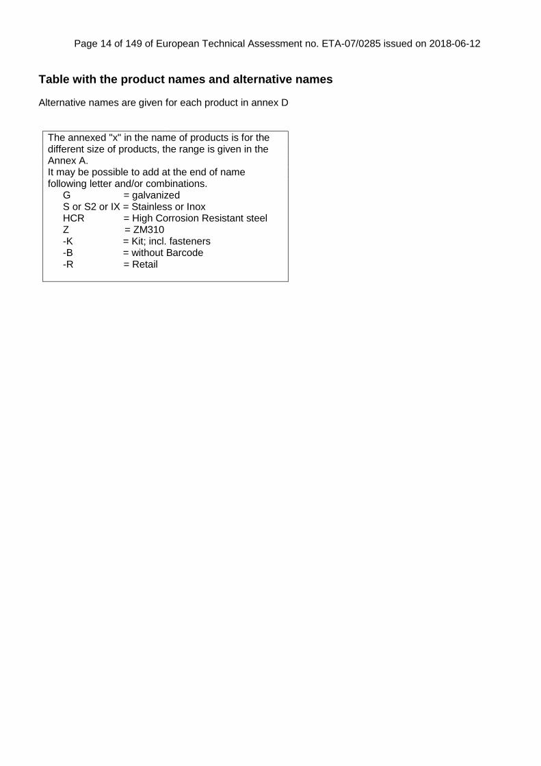
Table with the product names and alternative names
Alternative names are given for each product in annex D
The annexed "x" in the name of products is for the different size of products, the range is given in the Annex A. It may be possible to add at the end of name following letter and/or combinations.
G = galvanized S or S2 or IX = Stainless or Inox HCR = High Corrosion Resistant steel Z = ZM310 -K = Kit; incl. fasteners -B = without Barcode -R = Retail
Page 15 of 149 of European Technical Assessment no. ETA-07/0285 issued on 2018-06-12
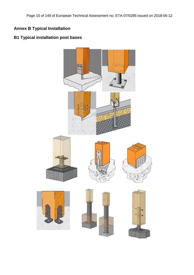
Annex B Typical Installation
B1 Typical installation post bases
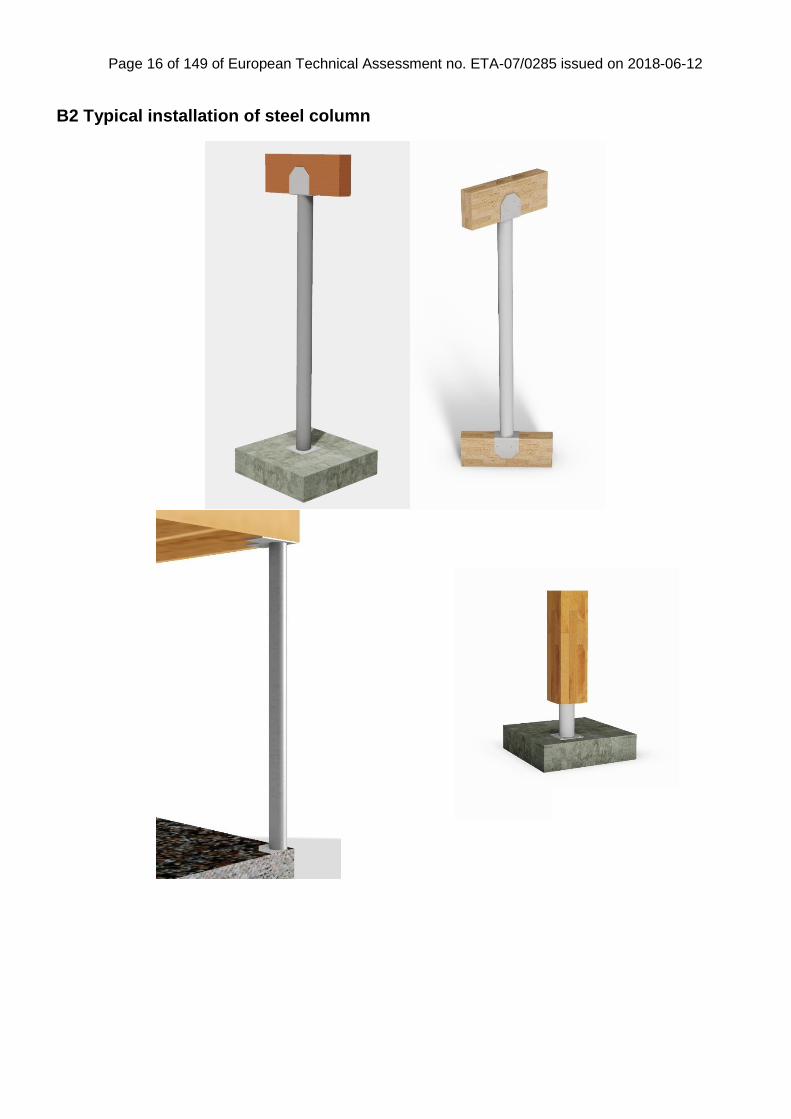
Page 16 of 149 of European Technical Assessment no. ETA-07/0285 issued on 2018-06-12
B2 Typical installation of steel column
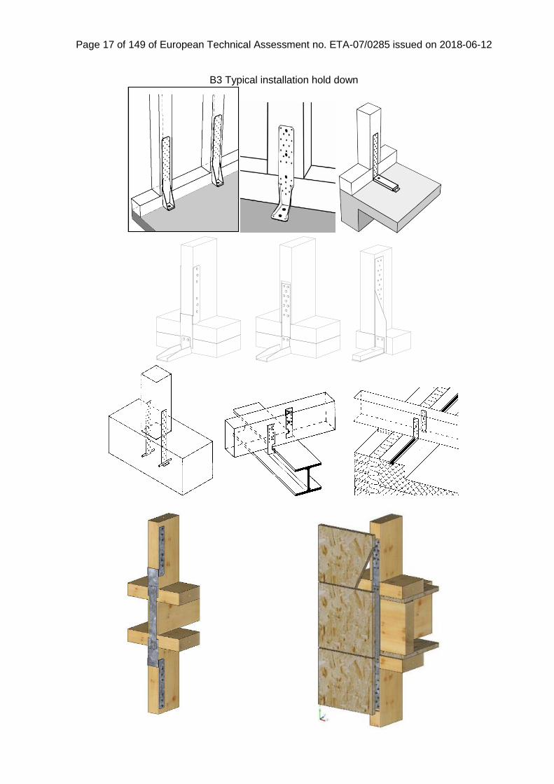
Page 17 of 149 of European Technical Assessment no. ETA-07/0285 issued on 2018-06-12
B3 Typical installation hold down
Page 18 of 149 of European Technical Assessment no. ETA-07/0285 issued on 2018-06-12
Annex C Basis of design
C0 Symbols used in the ETA-07/0285
For the purpose of ETA-06/0270, the following symbols apply.
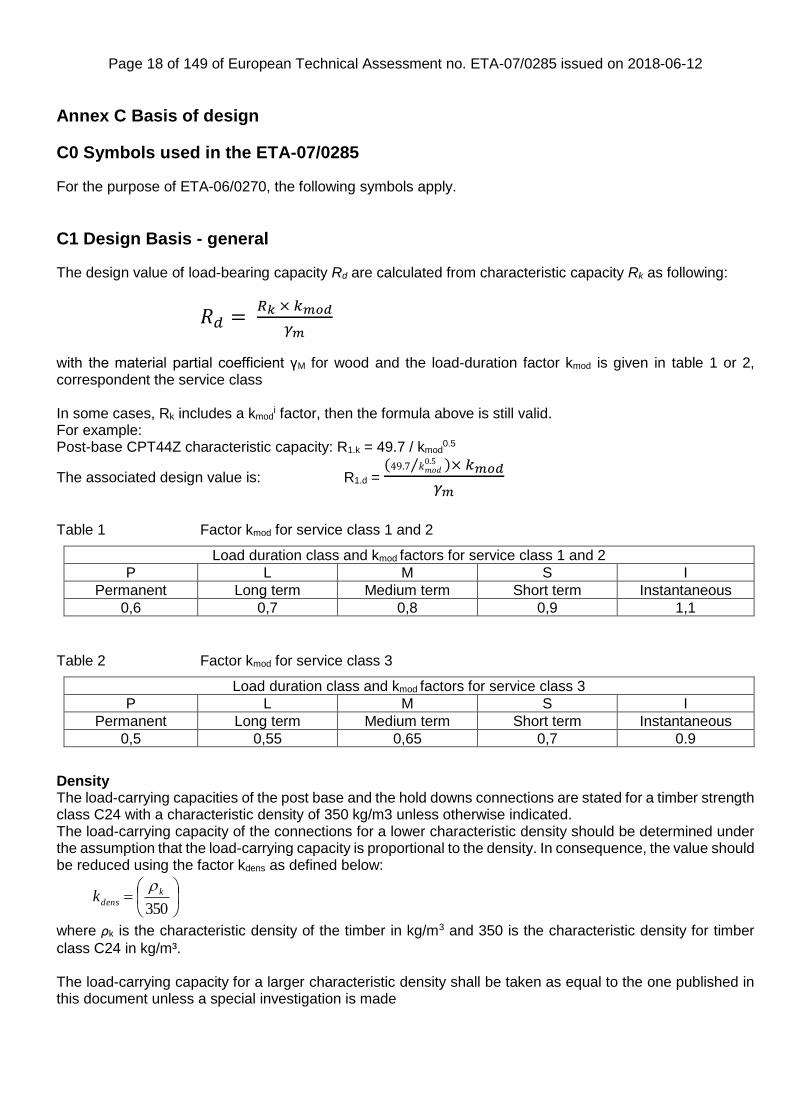
C1 Design Basis - general
The design value of load-bearing capacity Rd are calculated from characteristic capacity Rk as following:
𝑅𝑑 = 𝑅𝑘 × 𝑘𝑚𝑜𝑑
𝛾𝑚
with the material partial coefficient γM for wood and the load-duration factor kmod is given in table 1 or 2, correspondent the service class In some cases, Rk includes a kmod
i factor, then the formula above is still valid. For example: Post-base CPT44Z characteristic capacity: R1.k = 49.7 / kmod
0.5
The associated design value is: R1.d = (49.7 𝑘𝑚𝑜𝑑
0.5⁄ )× 𝑘𝑚𝑜𝑑
𝛾𝑚
Table 1 Factor kmod for service class 1 and 2
Load duration class and kmod factors for service class 1 and 2
P L M S I
Permanent Long term Medium term Short term Instantaneous
0,6 0,7 0,8 0,9 1,1
Table 2 Factor kmod for service class 3
Load duration class and kmod factors for service class 3
P L M S I
Permanent Long term Medium term Short term Instantaneous
0,5 0,55 0,65 0,7 0.9
Density The load-carrying capacities of the post base and the hold downs connections are stated for a timber strength class C24 with a characteristic density of 350 kg/m3 unless otherwise indicated. The load-carrying capacity of the connections for a lower characteristic density should be determined under the assumption that the load-carrying capacity is proportional to the density. In consequence, the value should be reduced using the factor kdens as defined below:
350
k
densk
where ρk is the characteristic density of the timber in kg/m3 and 350 is the characteristic density for timber
class C24 in kg/m³.
The load-carrying capacity for a larger characteristic density shall be taken as equal to the one published in this document unless a special investigation is made

Page 19 of 149 of European Technical Assessment no. ETA-07/0285 issued on 2018-06-12
Concrete The load-carrying capacities of the post base connections are stated for a concrete class C15 unless otherwise indicated. Installation with bonded anchorage The post bases of types: PJIS, PLS, PJPS, PPS, PI, PP, PPD may be installed in reinforced or unreinforced normal weight concrete of strength class C20/25 at minimum as a post-installed-anchorage with injection system Simpson Strong -Tie ® SET-XP Epoxy Adhesive Injection System (acc. ETA-11/0360) or Simpson Strong-Tie ® AT-HP™ (acc. ETA-14/0383(thread) ETA-11/0139 (rebar)). The design of the anchorage installation shall be performed in accordance with the latest versions of the equivalent European technical approval (ETA).
Injection Mortar System
Drill hole diameter d0
Threaded rod Reinforcement bar
M16 M20 Ø16 Ø20
SET-XP 18 mm 24 mm 20 mm 25 mm
AT-HP 18 mm 22 mm -/- -/-
Wane Where force is carried by contact compression no wane may occur. Where the lateral force is acting toward a Hold Down connector the force is carried by contact compression so for this case no wane may occur in the surface of the timber under the vertical flap. Additionally, no wane may occur under the nails. Fastening Unless otherwise indicated in the calculations the holes in the post bases have to be fully applied with the applicable fasteners. The fastener types for which the calculations have been made are stated at each post base. The nail pattern shall be as described in Annex D. The fastener types for which the calculations have been made are stated at the relevant post bases and hold downs. The thickness of the beam shall be a minimum of the embedment depth of the nails or screws. Assumed characteristic capacities of anchor bolts The capacity of the anchor bolts are to be checked. The calculations to use corresponding to the forces are outlined below: For a lateral load: the axial force for the bolt: Faxial,bolt = F3 x e / f Flateral,bolt = F3 / n For an uplift load: Faxial,bolt = Fup / n With n = number of bolts. The above method should be used to check anchor bolt capacities unless otherwise stated alongside the product details.
h
d
0
0
threaded rodorreinforcement bar

Page 20 of 149 of European Technical Assessment no. ETA-07/0285 issued on 2018-06-12
g g g
C2 Definition of force directions
C2a Force directions for post bases
Figure C2a.Typical connection with notation for loads. The actual force directions are indicated for each post base
The capacities in the tables are stated in kN and kNm. Gap The gap (g) is the distance from the top side of the concrete to the top side of the top plate. The gap is stated for each post base in the following. Acting forces Unless otherwise indicated in the tables with load-carrying capacities, the forces are assumed to act as described below: F1 Load-carrying capacity for downward load acting along the central axis of the joint F2 Load-carrying capacity for upward load acting along the central axis of the joint F3 Load-carrying capacity for lateral load acting in the centre of the post in line with the lower row of holes F4 Load-carrying capacity for axial load acting in the centre of the compression zone at the bottom of the
timber member M1/2 are described by types CMR and CMS Combined forces In the following tables the load-carrying capacities are given for the individual loads: F1, F2, F3 and F4. For combinations of loads, the following equation shall be fulfilled, unless otherwise indicated.
∑(𝐹𝑖𝑅𝑖) ≤ 1.0
𝑖
For horizontal loads F3 and F4 acting simultaneously the resulting horizontal load shall be calculated as
𝐹3/4 = √𝐹32 + 𝐹4
2
Page 21 of 149 of European Technical Assessment no. ETA-07/0285 issued on 2018-06-12
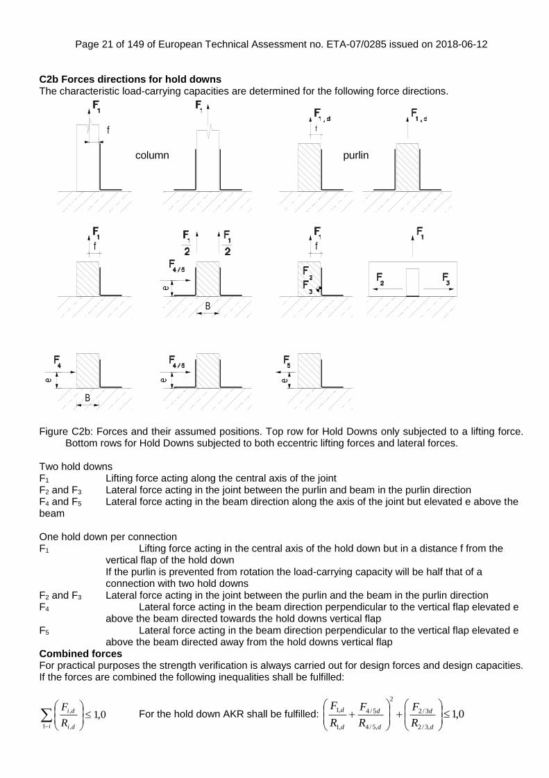
C2b Forces directions for hold downs The characteristic load-carrying capacities are determined for the following force directions.
Figure C2b: Forces and their assumed positions. Top row for Hold Downs only subjected to a lifting force.
Bottom rows for Hold Downs subjected to both eccentric lifting forces and lateral forces. Two hold downs F1 Lifting force acting along the central axis of the joint F2 and F3 Lateral force acting in the joint between the purlin and beam in the purlin direction F4 and F5 Lateral force acting in the beam direction along the axis of the joint but elevated e above the beam One hold down per connection F1 Lifting force acting in the central axis of the hold down but in a distance f from the
vertical flap of the hold down If the purlin is prevented from rotation the load-carrying capacity will be half that of a connection with two hold downs
F2 and F3 Lateral force acting in the joint between the purlin and the beam in the purlin direction F4 Lateral force acting in the beam direction perpendicular to the vertical flap elevated e
above the beam directed towards the hold downs vertical flap F5 Lateral force acting in the beam direction perpendicular to the vertical flap elevated e
above the beam directed away from the hold downs vertical flap Combined forces For practical purposes the strength verification is always carried out for design forces and design capacities. If the forces are combined the following inequalities shall be fulfilled:
0,11 ,
,
i di
di
R
F For the hold down AKR shall be fulfilled:
f
eee
B
e
f
f
f
B
column purlin
0,1,3/2
3/2
2
,5/4
5/4
,1
,1
d
d
d
d
d
d
R
F
R
F
R
F

Page 22 of 149 of European Technical Assessment no. ETA-07/0285 issued on 2018-06-12
The capacity can be limited by the capacity of the anchor bolt. This has to be investigated separately, see below. Additional conditions The nail pattern shall be as described in Annex D. The fastener types for which the calculations have been made are stated at the relevant hold downs. The thickness of the beam shall be according to Eurocode 5, tpen shall be min. 6d, where d is the diameter of the nail or screw.
Page 23 of 149 of European Technical Assessment no. ETA-07/0285 issued on 2018-06-12
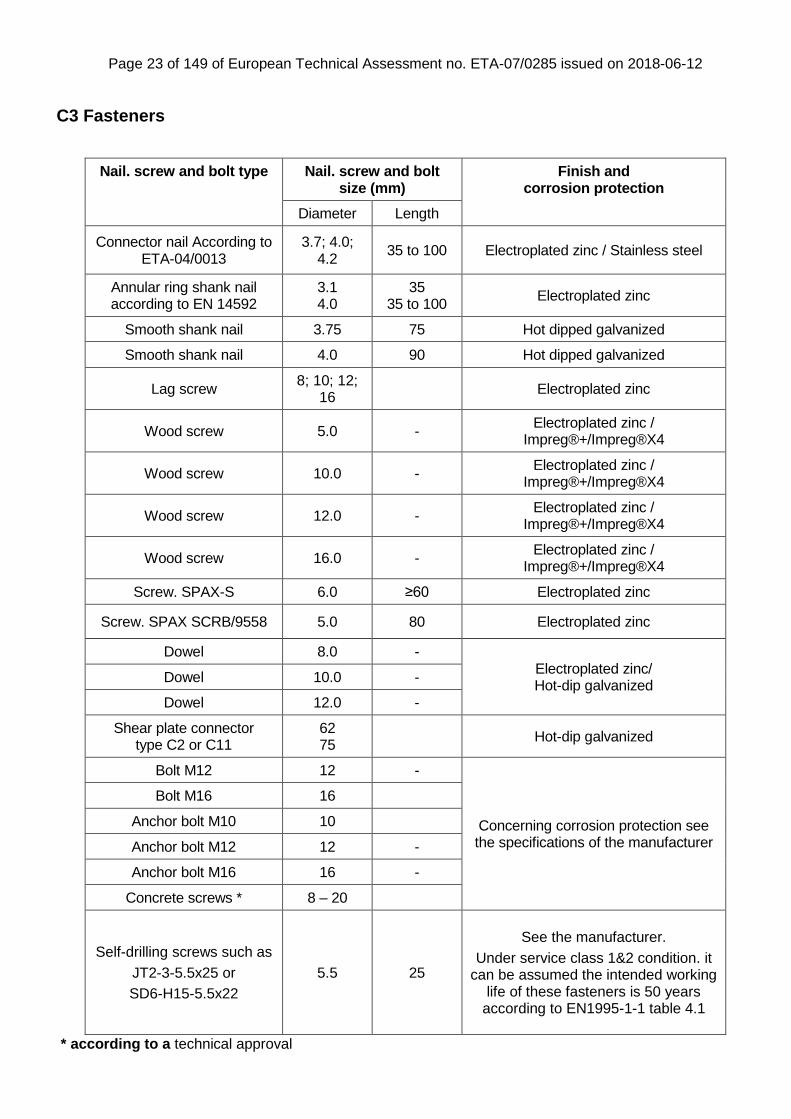
C3 Fasteners
Nail. screw and bolt type Nail. screw and bolt size (mm)
Finish and corrosion protection
Diameter Length
Connector nail According to ETA-04/0013
3.7; 4.0; 4.2
35 to 100 Electroplated zinc / Stainless steel
Annular ring shank nail according to EN 14592
3.1 4.0
35 35 to 100
Electroplated zinc
Smooth shank nail 3.75 75 Hot dipped galvanized
Smooth shank nail 4.0 90 Hot dipped galvanized
Lag screw 8; 10; 12;
16 Electroplated zinc
Wood screw 5.0 - Electroplated zinc /
Impreg®+/Impreg®X4
Wood screw 10.0 - Electroplated zinc /
Impreg®+/Impreg®X4
Wood screw 12.0 - Electroplated zinc /
Impreg®+/Impreg®X4
Wood screw 16.0 - Electroplated zinc /
Impreg®+/Impreg®X4
Screw. SPAX-S 6.0 ≥60 Electroplated zinc
Screw. SPAX SCRB/9558 5.0 80 Electroplated zinc
Dowel 8.0 - Electroplated zinc/ Hot-dip galvanized
Dowel 10.0 -
Dowel 12.0 -
Shear plate connector type C2 or C11
62 75
Hot-dip galvanized
Bolt M12 12 -
Concerning corrosion protection see the specifications of the manufacturer
Bolt M16 16
Anchor bolt M10 10
Anchor bolt M12 12 -
Anchor bolt M16 16 -
Concrete screws * 8 – 20
Self-drilling screws such as
JT2-3-5.5x25 or
SD6-H15-5.5x22
5.5 25
See the manufacturer.
Under service class 1&2 condition. it can be assumed the intended working
life of these fasteners is 50 years according to EN1995-1-1 table 4.1
* according to a technical approval
Page 24 of 149 of European Technical Assessment no. ETA-07/0285 issued on 2018-06-12
Annex D Product definition and capacities Post Bases
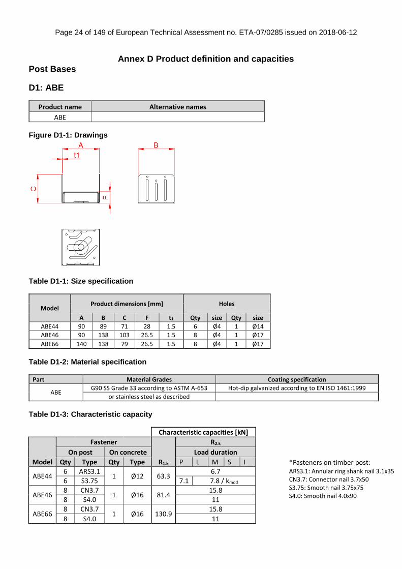
D1: ABE
Product name Alternative names
ABE Figure D1-1: Drawings
Table D1-1: Size specification
Model Product dimensions [mm] Holes
A B C F t1 Qty size Qty size
ABE44 90 89 71 28 1.5 6 Ø4 1 Ø14
ABE46 90 138 103 26.5 1.5 8 Ø4 1 Ø17
ABE66 140 138 79 26.5 1.5 8 Ø4 1 Ø17
Table D1-2: Material specification
Part Material Grades Coating specification
ABE G90 SS Grade 33 according to ASTM A-653 Hot-dip galvanized according to EN ISO 1461:1999
or stainless steel as described
Table D1-3: Characteristic capacity
Characteristic capacities [kN]
Model
Fastener
R1.k
R2.k
On post On concrete Load duration
Qty Type Qty Type P L M S I
ABE44 6 ARS3.1
1 Ø12 63.3 6.7
6 S3.75 7.1 7.8 / kmod
ABE46 8 CN3.7
1 Ø16 81.4 15.8
8 S4.0 11
ABE66 8 CN3.7
1 Ø16 130.9 15.8
8 S4.0 11
*Fasteners on timber post: ARS3.1: Annular ring shank nail 3.1x35 CN3.7: Connector nail 3.7x50 S3.75: Smooth nail 3.75x75 S4.0: Smooth nail 4.0x90
Page 25 of 149 of European Technical Assessment no. ETA-07/0285 issued on 2018-06-12
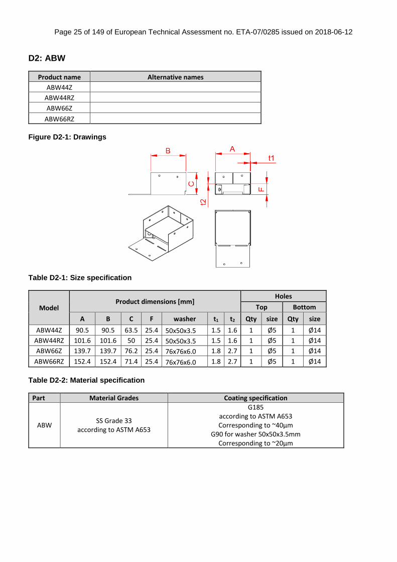
D2: ABW
Product name Alternative names
ABW44Z
ABW44RZ
ABW66Z
ABW66RZ
Figure D2-1: Drawings
Table D2-1: Size specification
Model Product dimensions [mm]
Holes
Top Bottom
A B C F washer t1 t2 Qty size Qty size
ABW44Z 90.5 90.5 63.5 25.4 50x50x3.5 1.5 1.6 1 Ø5 1 Ø14
ABW44RZ 101.6 101.6 50 25.4 50x50x3.5 1.5 1.6 1 Ø5 1 Ø14
ABW66Z 139.7 139.7 76.2 25.4 76x76x6.0 1.8 2.7 1 Ø5 1 Ø14
ABW66RZ 152.4 152.4 71.4 25.4 76x76x6.0 1.8 2.7 1 Ø5 1 Ø14
Table D2-2: Material specification
Part Material Grades Coating specification
ABW SS Grade 33
according to ASTM A653
G185 according to ASTM A653 Corresponding to ~40µm
G90 for washer 50x50x3.5mm Corresponding to ~20µm
Page 26 of 149 of European Technical Assessment no. ETA-07/0285 issued on 2018-06-12
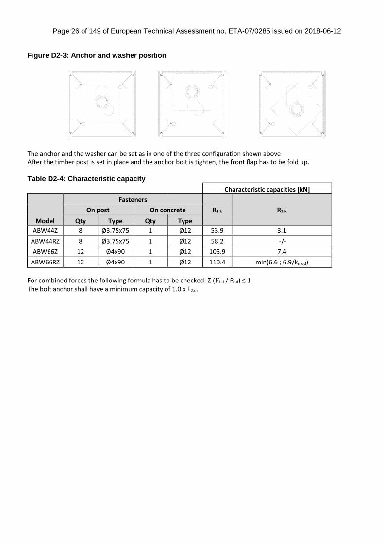
Figure D2-3: Anchor and washer position
The anchor and the washer can be set as in one of the three configuration shown above After the timber post is set in place and the anchor bolt is tighten, the front flap has to be fold up. Table D2-4: Characteristic capacity
Characteristic capacities [kN]
Model
Fasteners
R1.k R2.k On post On concrete
Qty Type Qty Type
ABW44Z 8 Ø3.75x75 1 Ø12 53.9 3.1
ABW44RZ 8 Ø3.75x75 1 Ø12 58.2 -/-
ABW66Z 12 Ø4x90 1 Ø12 105.9 7.4
ABW66RZ 12 Ø4x90 1 Ø12 110.4 min(6.6 ; 6.9/kmod)
For combined forces the following formula has to be checked: Σ (Fi.d / Ri.d) ≤ 1 The bolt anchor shall have a minimum capacity of 1.0 x F2.d.
Page 27 of 149 of European Technical Assessment no. ETA-07/0285 issued on 2018-06-12
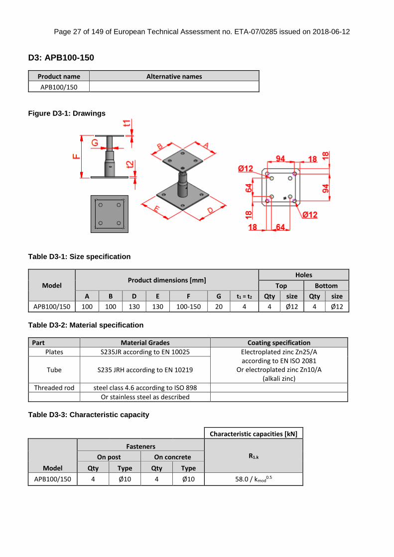
D3: APB100-150
Product name Alternative names
APB100/150
Figure D3-1: Drawings
Table D3-1: Size specification
Model Product dimensions [mm]
Holes
Top Bottom
A B D E F G t1 = t2 Qty size Qty size
APB100/150 100 100 130 130 100-150 20 4 4 Ø12 4 Ø12
Table D3-2: Material specification
Part Material Grades Coating specification
Plates S235JR according to EN 10025 Electroplated zinc Zn25/A according to EN ISO 2081
Or electroplated zinc Zn10/A (alkali zinc)
Tube S235 JRH according to EN 10219
Threaded rod steel class 4.6 according to ISO 898
Or stainless steel as described
Table D3-3: Characteristic capacity
Characteristic capacities [kN]
Model
Fasteners
R1.k On post On concrete
Qty Type Qty Type
APB100/150 4 Ø10 4 Ø10 58.0 / kmod0.5
Page 28 of 149 of European Technical Assessment no. ETA-07/0285 issued on 2018-06-12
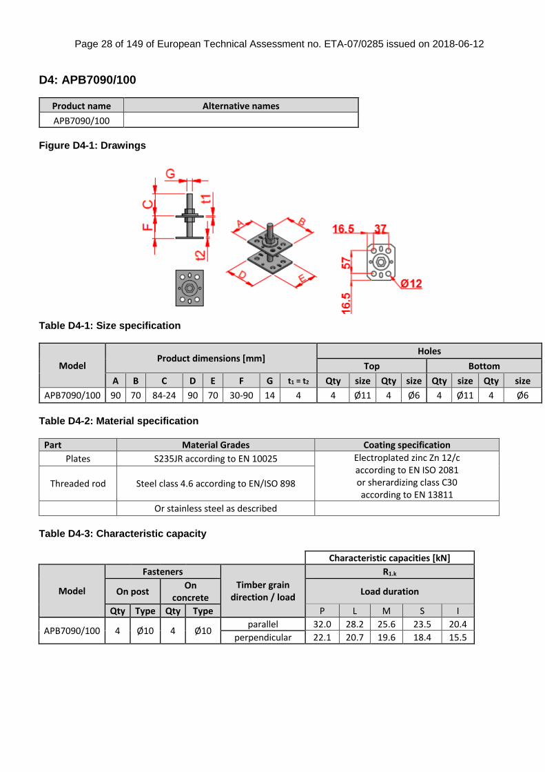
D4: APB7090/100
Product name Alternative names
APB7090/100
Figure D4-1: Drawings
Table D4-1: Size specification
Model Product dimensions [mm]
Holes
Top Bottom
A B C D E F G t1 = t2 Qty size Qty size Qty size Qty size
APB7090/100 90 70 84-24 90 70 30-90 14 4 4 Ø11 4 Ø6 4 Ø11 4 Ø6
Table D4-2: Material specification
Part Material Grades Coating specification
Plates S235JR according to EN 10025 Electroplated zinc Zn 12/c according to EN ISO 2081 or sherardizing class C30 according to EN 13811
Threaded rod Steel class 4.6 according to EN/ISO 898
Or stainless steel as described
Table D4-3: Characteristic capacity
Characteristic capacities [kN]
Model
Fasteners
Timber grain direction / load
R1.k
On post On
concrete Load duration
Qty Type Qty Type P L M S I
APB7090/100 4 Ø10 4 Ø10 parallel 32.0 28.2 25.6 23.5 20.4
perpendicular 22.1 20.7 19.6 18.4 15.5
Page 29 of 149 of European Technical Assessment no. ETA-07/0285 issued on 2018-06-12
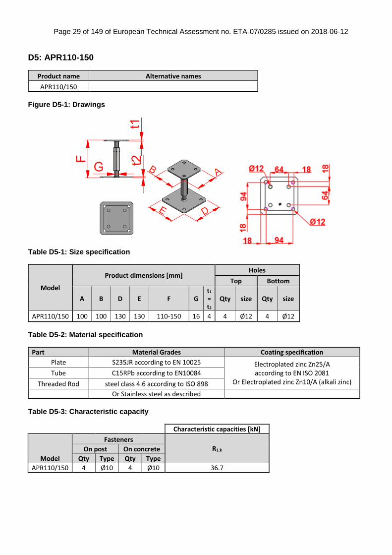
D5: APR110-150
Product name Alternative names
APR110/150
Figure D5-1: Drawings
Table D5-1: Size specification
Model
Product dimensions [mm] Holes
Top Bottom
A B D E F G t1 = t2
Qty size Qty size
APR110/150 100 100 130 130 110-150 16 4 4 Ø12 4 Ø12
Table D5-2: Material specification
Part Material Grades Coating specification
Plate S235JR according to EN 10025 Electroplated zinc Zn25/A according to EN ISO 2081
Or Electroplated zinc Zn10/A (alkali zinc) Tube C15RPb according to EN10084
Threaded Rod steel class 4.6 according to ISO 898
Or Stainless steel as described
Table D5-3: Characteristic capacity
Characteristic capacities [kN]
Model
Fasteners R1.k On post On concrete
Qty Type Qty Type
APR110/150 4 Ø10 4 Ø10 36.7
Page 30 of 149 of European Technical Assessment no. ETA-07/0285 issued on 2018-06-12
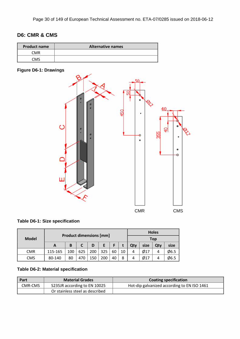
D6: CMR & CMS
Product name Alternative names
CMR
CMS
Figure D6-1: Drawings
CMR CMS
Table D6-1: Size specification
Model Product dimensions [mm]
Holes
Top
A B C D E F t Qty size Qty size
CMR 115-165 100 625 200 325 60 10 4 Ø17 4 Ø6.5
CMS 80-140 80 470 150 200 40 8 4 Ø17 4 Ø6.5
Table D6-2: Material specification
Part Material Grades Coating specification
CMR-CMS S235JR according to EN 10025 Hot-dip galvanized according to EN ISO 1461
Or stainless steel as described

Page 31 of 149 of European Technical Assessment no. ETA-07/0285 issued on 2018-06-12
Table D6-3: Characteristic capacity – for concrete C12/16
Characteristic capacities [kN]
Model
Fasteners Timber size
(mm) R1.k = R2.k R3.k for h1 = 200 mm R4.k for h2 = 0 mm Mr1.k Mr2.k
On post
Qty Type
CMR 2 + 4
bolt Ø16 + C2-
75
115
117.2 min( 99; 21.3/kmod ) min(33; 30.9/kmod) min(19.8; 13.9/kmod)
6.7
120 7
125 7.3
140 8.2
150 8.8
160 9.4
CMS 2 + 4
bolt Ø16 + C2-
62
80
96.7 min( 74; 15.0/kmod) min(21.1; 19.8/kmod) min(11.6; 7.1/kmod)
3.9
100 4.8
120 5.8
140 6.8
The post-base shall be embedded in concrete in depth equal to dimension E. For a load F3 acting at the height h1 > 200 mm for CMR (for CMS h1 > 157mm) the load carrying capacity shall not be taken as higher than: For CMR : R3(h) = R3(200) * 200 / h1. For CMS: R3(h) = R3(157) * 157 / h1. For a load F4 acting at the height h2 > 0 mm, the load carrying capacity shall not be taken higher than: R4 (h) = ½ R4 * a / h2. where: a is the inner distance between the vertical steel plates e.g. the column depth. For a vertical load F (either F1 or F2) and a horizontal load F3 acting simultaneously it should be verified that (F/R1/2)2 + (F3 /R3)2 ≤ 1 For a vertical load F (either F1 or F2) and a horizontal load F4 in the height h acting simultaneously it should be verified that R4(h) ≤ Mr2 / (h (1 – F / R1)) For combined loads the following check shall be made:
(𝐹1/2.𝑑
𝑅1/2.𝑑)2
+ (𝐹3.𝑑
𝑅3.𝑑+
𝑀1.𝑑
𝑀𝑟1.𝑑)2≤ 1
(𝐹1/2.𝑑
𝑅1/2.𝑑+
𝑀2.𝑑
𝑀𝑟2.𝑑)2
+ (𝐹4.𝑑
𝑅4.𝑑)2≤ 1
Page 32 of 149 of European Technical Assessment no. ETA-07/0285 issued on 2018-06-12
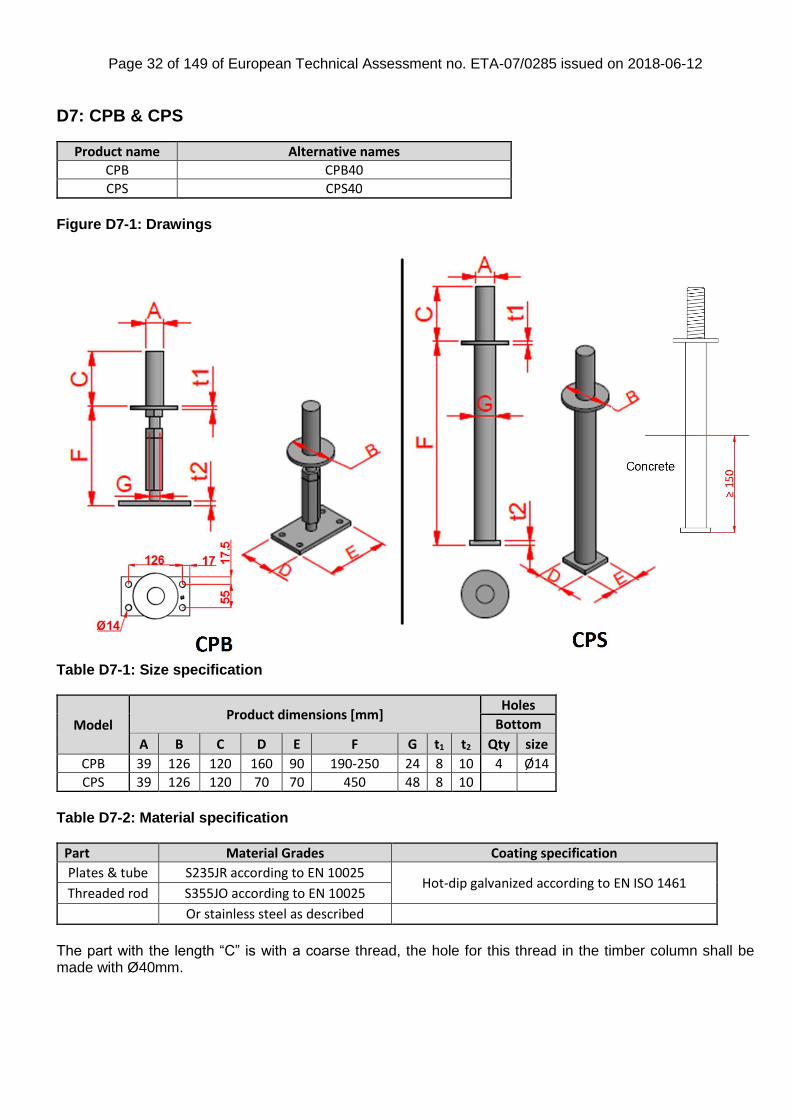
D7: CPB & CPS
Product name Alternative names
CPB CPB40
CPS CPS40
Figure D7-1: Drawings
Table D7-1: Size specification
Model Product dimensions [mm]
Holes
Bottom
A B C D E F G t1 t2 Qty size
CPB 39 126 120 160 90 190-250 24 8 10 4 Ø14
CPS 39 126 120 70 70 450 48 8 10
Table D7-2: Material specification
Part Material Grades Coating specification
Plates & tube S235JR according to EN 10025 Hot-dip galvanized according to EN ISO 1461
Threaded rod S355JO according to EN 10025
Or stainless steel as described
The part with the length “C” is with a coarse thread, the hole for this thread in the timber column shall be made with Ø40mm.

Page 33 of 149 of European Technical Assessment no. ETA-07/0285 issued on 2018-06-12
Table D7-3: Characteristic capacity
Characteristic capacities [kN]
Model
Fasteners
R1.k R1.k ** R2.k R2.k **
R3.k = R4.k
On concrete f
Qty Type 190 250
CPB 4 Ø12 61/kmod 23.7 13.8 1.7 1.4
CPS min( 170.3; 118.7/kmod) 110.7 23.7 13.8 min( 7.2; 5.2/kmod)
** In cases where the post base can be submitted to uplift AND download f is the distance between concrete surface and post surface For vertical load F1 and horizontal load F3 or F4 acting simultaneously it shall be verified that: F1 / R1.d + F3/4 / R3/4.d ≤ 1

Page 34 of 149 of European Technical Assessment no. ETA-07/0285 issued on 2018-06-12
D8: CPT
Product name Alternative names
CPT44Z
CPT66Z
CPT88Z
Figure D8-1: Drawings
Table D8-1: Size specification
Model Product dimensions [mm]
Holes
Top Bottom
A B C F H washer t1 t2 Qty size Qty size
CPT44Z 88.9 88.9 145 25.4 79.4 35.7x28.6x3.5 3.5 2.7 3 Ø13.5 2 Ø13.5
CPT66Z 136.5 136.5 145 25.4 114 35.7x28.6x3.5 3.5 2.7 3 Ø13.5 2 Ø13.5
CPT88Z 184 184 145 25.4 114 35.7x28.6x3.5 3.5 2.7 3 Ø13.5 2 Ø13.5
Table D8-2: Material specification
Part Material Grades Coating specification
CPT steel SS Grade 33 according to ASTM A653 G185 according to ASTM A653 Corresponding to ~40µm
Figure D8-2: Steel dowel pattern
Anchor bolts
washer
steel dowel
Page 35 of 149 of European Technical Assessment no. ETA-07/0285 issued on 2018-06-12
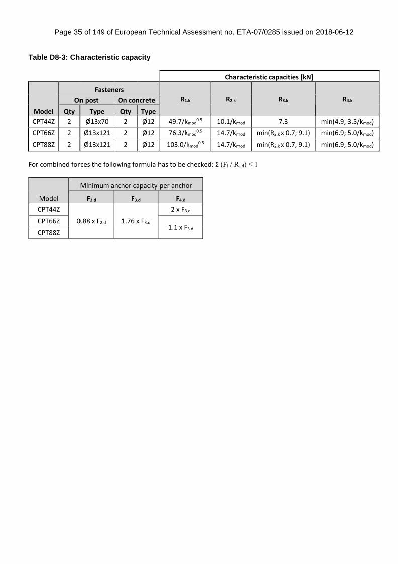
Table D8-3: Characteristic capacity
Characteristic capacities [kN]
Model
Fasteners
R1.k R2.k R3.k R4.k On post On concrete
Qty Type Qty Type
CPT44Z 2 Ø13x70 2 Ø12 49.7/kmod0.5 10.1/kmod 7.3 min(4.9; 3.5/kmod)
CPT66Z 2 Ø13x121 2 Ø12 76.3/kmod0.5 14.7/kmod min(R2.k x 0.7; 9.1) min(6.9; 5.0/kmod)
CPT88Z 2 Ø13x121 2 Ø12 103.0/kmod0.5 14.7/kmod min(R2.k x 0.7; 9.1) min(6.9; 5.0/kmod)
For combined forces the following formula has to be checked: Σ (Fi / Ri.d) ≤ 1
Model
Minimum anchor capacity per anchor
F2.d F3.d F4.d
CPT44Z
0.88 x F2.d 1.76 x F3.d
2 x F3.d
CPT66Z 1.1 x F3.d
CPT88Z
Page 36 of 149 of European Technical Assessment no. ETA-07/0285 issued on 2018-06-12
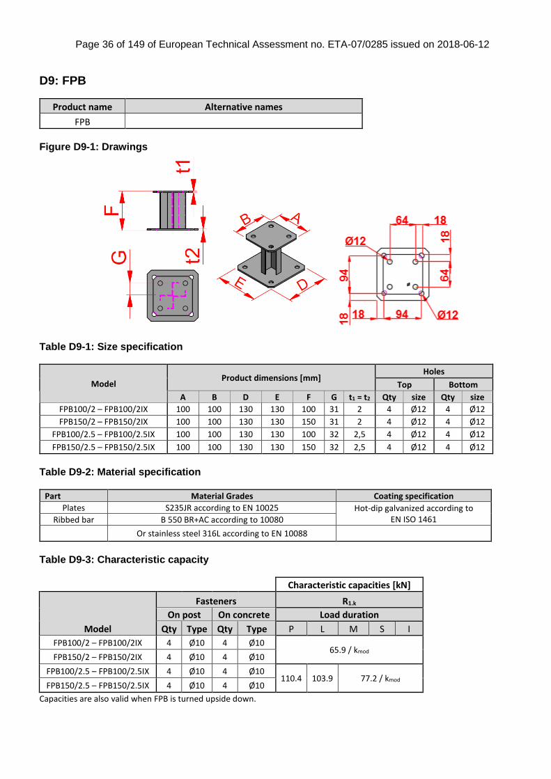
D9: FPB
Product name Alternative names
FPB
Figure D9-1: Drawings
Table D9-1: Size specification
Model Product dimensions [mm]
Holes
Top Bottom
A B D E F G t1 = t2 Qty size Qty size
FPB100/2 – FPB100/2IX 100 100 130 130 100 31 2 4 Ø12 4 Ø12
FPB150/2 – FPB150/2IX 100 100 130 130 150 31 2 4 Ø12 4 Ø12
FPB100/2.5 – FPB100/2.5IX 100 100 130 130 100 32 2,5 4 Ø12 4 Ø12
FPB150/2.5 – FPB150/2.5IX 100 100 130 130 150 32 2,5 4 Ø12 4 Ø12
Table D9-2: Material specification
Part Material Grades Coating specification
Plates S235JR according to EN 10025 Hot-dip galvanized according to EN ISO 1461 Ribbed bar B 550 BR+AC according to 10080
Or stainless steel 316L according to EN 10088
Table D9-3: Characteristic capacity
Characteristic capacities [kN]
Model
Fasteners R1.k
On post On concrete Load duration
Qty Type Qty Type P L M S I
FPB100/2 – FPB100/2IX 4 Ø10 4 Ø10 65.9 / kmod
FPB150/2 – FPB150/2IX 4 Ø10 4 Ø10
FPB100/2.5 – FPB100/2.5IX 4 Ø10 4 Ø10 110.4 103.9 77.2 / kmod
FPB150/2.5 – FPB150/2.5IX 4 Ø10 4 Ø10
Capacities are also valid when FPB is turned upside down.
Page 37 of 149 of European Technical Assessment no. ETA-07/0285 issued on 2018-06-12
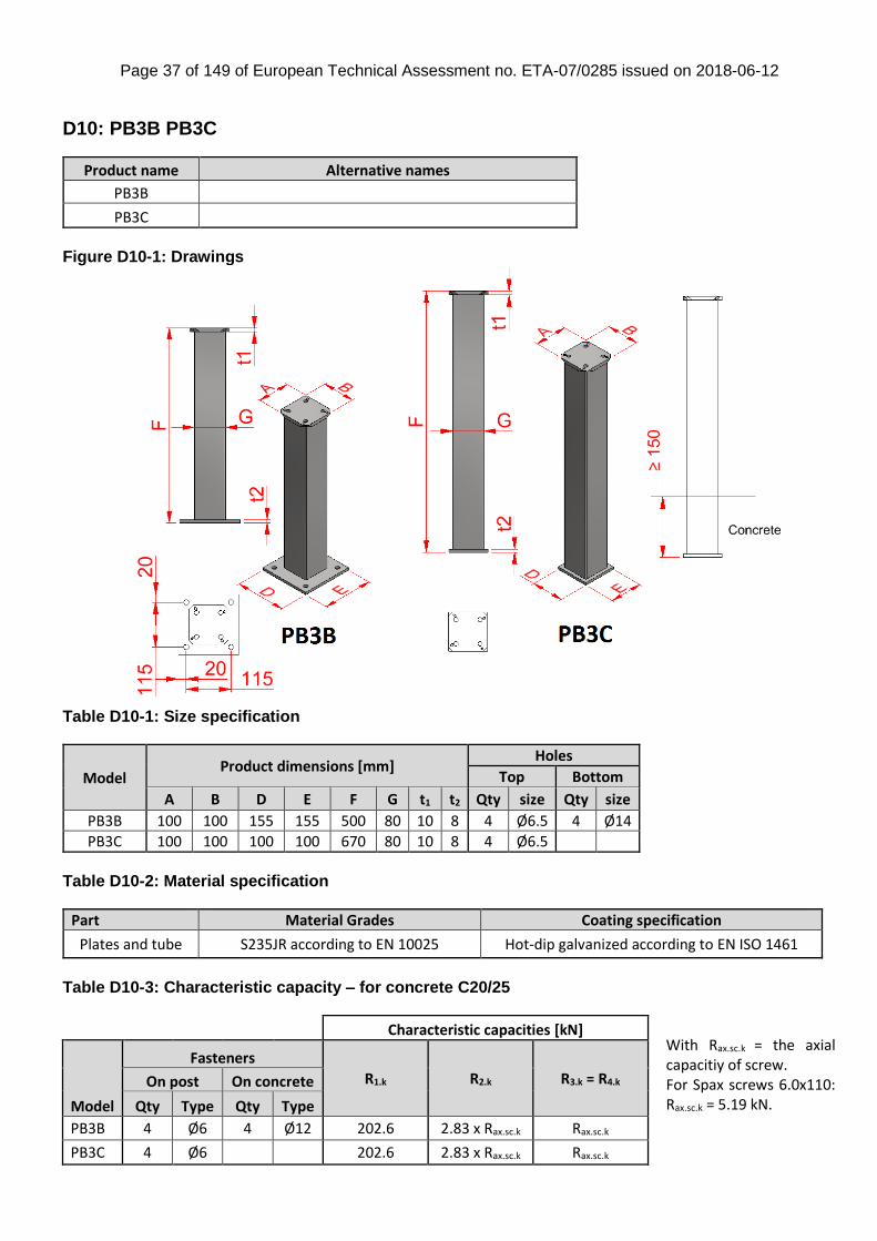
D10: PB3B PB3C
Product name Alternative names
PB3B
PB3C
Figure D10-1: Drawings
Table D10-1: Size specification
Model Product dimensions [mm]
Holes
Top Bottom
A B D E F G t1 t2 Qty size Qty size
PB3B 100 100 155 155 500 80 10 8 4 Ø6.5 4 Ø14
PB3C 100 100 100 100 670 80 10 8 4 Ø6.5
Table D10-2: Material specification
Part Material Grades Coating specification
Plates and tube S235JR according to EN 10025 Hot-dip galvanized according to EN ISO 1461
Table D10-3: Characteristic capacity – for concrete C20/25
Characteristic capacities [kN]
Model
Fasteners
R1.k R2.k R3.k = R4.k On post On concrete
Qty Type Qty Type
PB3B 4 Ø6 4 Ø12 202.6 2.83 x Rax.sc.k Rax.sc.k
PB3C 4 Ø6 202.6 2.83 x Rax.sc.k Rax.sc.k
With Rax.sc.k = the axial capacitiy of screw. For Spax screws 6.0x110: Rax.sc.k = 5.19 kN.
Page 38 of 149 of European Technical Assessment no. ETA-07/0285 issued on 2018-06-12
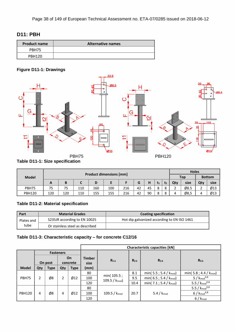
D11: PBH
Figure D11-1: Drawings
PBH75 PBH120
Table D11-1: Size specification
Model Product dimensions [mm]
Holes
Top Bottom
A B C D E F G H t1 t2 Qty size Qty size
PBH75 75 75 110 160 100 216 42 45 8 8 2 Ø8.5 2 Ø13
PBH120 120 120 110 155 155 216 42 90 8 8 4 Ø8,5 4 Ø13
Table D11-2: Material specification
Part Material Grades Coating specification
Plates and tube
S235JR according to EN 10025 Hot dip galvanized according to EN ISO 1461
Or stainless steel as described
Table D11-3: Characteristic capacity – for concrete C12/16
Characteristic capacities [kN]
Model
Fasteners
Timber size
(mm)
R1.k R2.k R3.k R4.k On post
On concrete
Qty Type Qty Type
PBH75 2 Ø8 2 Ø12
80 min( 105.5 ; 109.5 / kmod)
8.1 min( 5.5 ; 5.4 / kmod) min( 5.8 ; 4.4 / kmod)
100 9.5 min( 6.5 ; 5.4 / kmod) 5 / kmod0,8
120 10.4 min( 7.1 ; 5.4 / kmod) 5.5 / kmod0,8
PBH120 4 Ø8 4 Ø12
80
109.5 / kmod 20.7 5.4 / kmod
5.5 / kmod0,8
100 6 / kmod0,8
120 6 / kmod
Product name Alternative names
PBH75
PBH120
Page 39 of 149 of European Technical Assessment no. ETA-07/0285 issued on 2018-06-12
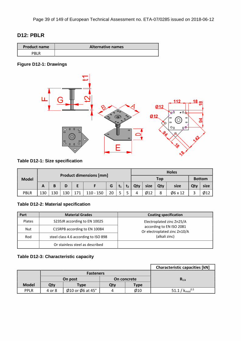
D12: PBLR
Product name Alternative names
PBLR
Figure D12-1: Drawings
Table D12-1: Size specification
Model Product dimensions [mm]
Holes
Top Bottom
A B D E F G t1 t2 Qty size Qty size Qty size
PBLR 130 130 130 171 110 - 150 20 5 5 4 Ø12 8 Ø6 x 12 3 Ø12
Table D12-2: Material specification
Part Material Grades Coating specification
Plates S235JR according to EN 10025 Electroplated zinc Zn25/A according to EN ISO 2081
Or electroplated zinc Zn10/A (alkali zinc)
Nut C15RPB according to EN 10084
Rod steel class 4.6 according to ISO 898
Or stainless steel as described
Table D12-3: Characteristic capacity
Characteristic capacities [kN]
Model
Fasteners
R1.k On post On concrete
Qty Type Qty Type
PPLR 4 or 8 Ø10 or Ø6 at 45° 4 Ø10 51.1 / kmod0.5
Page 40 of 149 of European Technical Assessment no. ETA-07/0285 issued on 2018-06-12
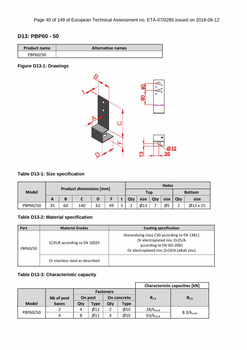
D13: PBP60 - 50
Product name Alternative names
PBP60/50
Figure D13-1: Drawings
Table D13-1: Size specification
Model Product dimensions [mm]
Holes
Top Bottom
A B C D F t Qty size Qty size Qty size
PBP60/50 35 60 140 62 49 3 2 Ø13 7 Ø5 1 Ø12 x 25
Table D13-2: Material specification
Part Material Grades Coating specification
PBP60/50
S235JR according to EN 10025
Sherardizing class C30 according to EN 13811 Or electroplated zinc Zn25/A
according to EN ISO 2081 Or electroplated zinc Zn10/A (alkali zinc)
Or stainless steel as described
Table D13-3: Characteristic capacity
Characteristic capacities [kN]
Model Nb of post
bases
Fasteners
R1.k R2.k On post On concrete
Qty Type Qty Type
PBP60/50 2 4 Ø12 2 Ø10 28/kmod
8.3/kmod 4 8 Ø12 4 Ø10 63/kmod
Page 41 of 149 of European Technical Assessment no. ETA-07/0285 issued on 2018-06-12
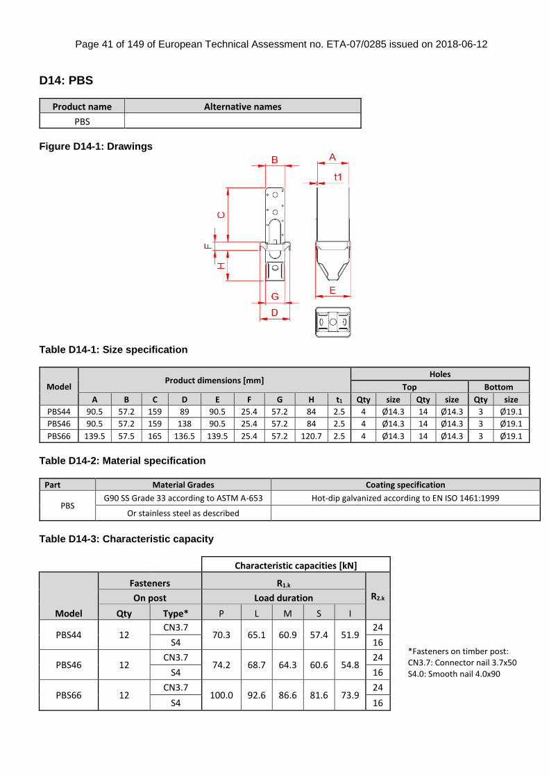
D14: PBS
Product name Alternative names
PBS
Figure D14-1: Drawings
Table D14-1: Size specification
Model Product dimensions [mm]
Holes
Top Bottom
A B C D E F G H t1 Qty size Qty size Qty size
PBS44 90.5 57.2 159 89 90.5 25.4 57.2 84 2.5 4 Ø14.3 14 Ø14.3 3 Ø19.1
PBS46 90.5 57.2 159 138 90.5 25.4 57.2 84 2.5 4 Ø14.3 14 Ø14.3 3 Ø19.1
PBS66 139.5 57.5 165 136.5 139.5 25.4 57.2 120.7 2.5 4 Ø14.3 14 Ø14.3 3 Ø19.1
Table D14-2: Material specification
Part Material Grades Coating specification
PBS G90 SS Grade 33 according to ASTM A-653 Hot-dip galvanized according to EN ISO 1461:1999
Or stainless steel as described
Table D14-3: Characteristic capacity
Characteristic capacities [kN]
Model
Fasteners R1.k
R2.k On post Load duration
Qty Type* P L M S I
PBS44 12 CN3.7
70.3 65.1 60.9 57.4 51.9 24
S4 16
PBS46 12 CN3.7
74.2 68.7 64.3 60.6 54.8 24
S4 16
PBS66 12 CN3.7
100.0 92.6 86.6 81.6 73.9 24
S4 16
*Fasteners on timber post: CN3.7: Connector nail 3.7x50 S4.0: Smooth nail 4.0x90
Page 42 of 149 of European Technical Assessment no. ETA-07/0285 issued on 2018-06-12
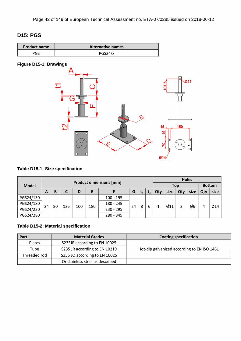
D15: PGS
Product name Alternative names
PGS PGS24/x
Figure D15-1: Drawings
Table D15-1: Size specification
Model Product dimensions [mm]
Holes
Top Bottom
A B C D E F G t1 t2 Qty size Qty size Qty size
PGS24/130
24 80 125 100 180
100 - 195
24 8 6 1 Ø11 3 Ø6 4 Ø14 PGS24/180 180 - 245
PGS24/230 230 - 295
PGS24/280 280 - 345
Table D15-2: Material specification
Part Material Grades Coating specification
Plates S235JR according to EN 10025
Hot-dip galvanized according to EN ISO 1461 Tube S235 JR according to EN 10219
Threaded rod S355 JO according to EN 10025
Or stainless steel as described
Page 43 of 149 of European Technical Assessment no. ETA-07/0285 issued on 2018-06-12
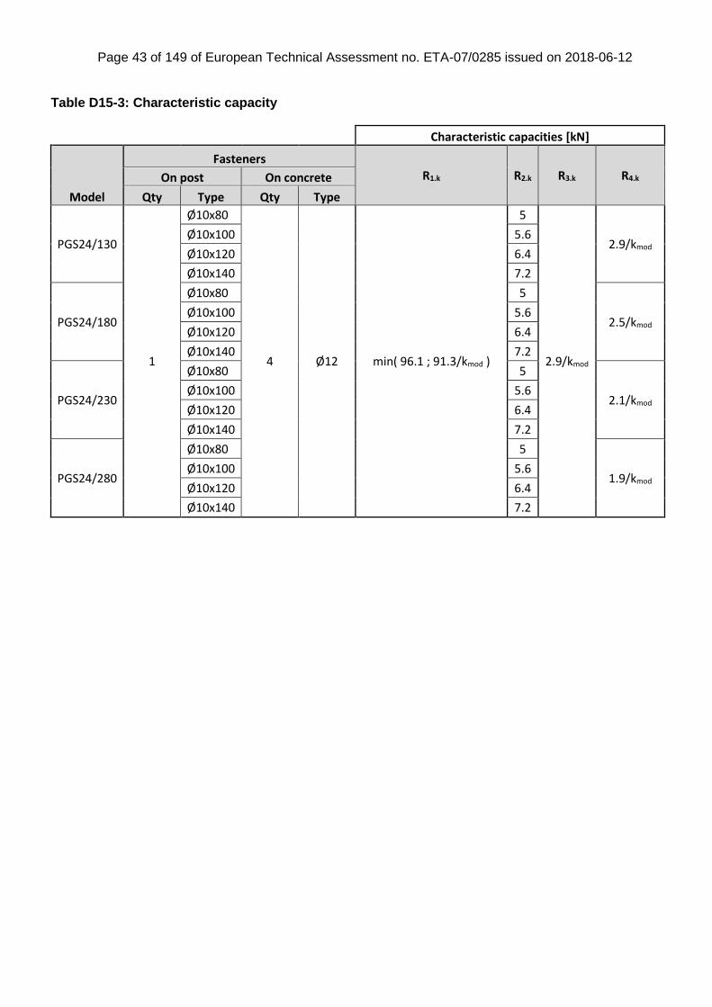
Table D15-3: Characteristic capacity
Characteristic capacities [kN]
Model
Fasteners
R1.k R2.k R3.k R4.k On post On concrete
Qty Type Qty Type
PGS24/130
1
Ø10x80
4 Ø12 min( 96.1 ; 91.3/kmod )
5
2.9/kmod
2.9/kmod Ø10x100 5.6
Ø10x120 6.4
Ø10x140 7.2
PGS24/180
Ø10x80 5
2.5/kmod Ø10x100 5.6
Ø10x120 6.4
Ø10x140 7.2
PGS24/230
Ø10x80 5
2.1/kmod Ø10x100 5.6
Ø10x120 6.4
Ø10x140 7.2
PGS24/280
Ø10x80 5
1.9/kmod Ø10x100 5.6
Ø10x120 6.4
Ø10x140 7.2
Page 44 of 149 of European Technical Assessment no. ETA-07/0285 issued on 2018-06-12
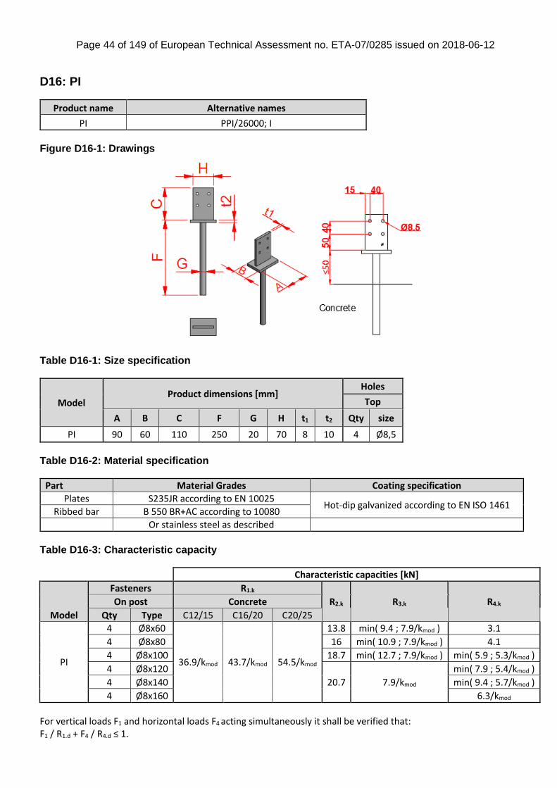
D16: PI
Product name Alternative names
PI PPI/26000; I
Figure D16-1: Drawings
Table D16-1: Size specification
Model Product dimensions [mm]
Holes
Top
A B C F G H t1 t2 Qty size
PI 90 60 110 250 20 70 8 10 4 Ø8,5
Table D16-2: Material specification
Part Material Grades Coating specification
Plates S235JR according to EN 10025 Hot-dip galvanized according to EN ISO 1461
Ribbed bar B 550 BR+AC according to 10080
Or stainless steel as described
Table D16-3: Characteristic capacity
Characteristic capacities [kN]
Model
Fasteners R1.k
R2.k R3.k R4.k On post Concrete
Qty Type C12/15 C16/20 C20/25
PI
4 Ø8x60
36.9/kmod 43.7/kmod 54.5/kmod
13.8 min( 9.4 ; 7.9/kmod ) 3.1
4 Ø8x80 16 min( 10.9 ; 7.9/kmod ) 4.1
4 Ø8x100 18.7 min( 12.7 ; 7.9/kmod ) min( 5.9 ; 5.3/kmod )
4 Ø8x120
20.7 7.9/kmod
min( 7.9 ; 5.4/kmod )
4 Ø8x140 min( 9.4 ; 5.7/kmod )
4 Ø8x160 6.3/kmod
For vertical loads F1 and horizontal loads F4 acting simultaneously it shall be verified that: F1 / R1.d + F4 / R4.d ≤ 1.

Page 45 of 149 of European Technical Assessment no. ETA-07/0285 issued on 2018-06-12
D17: PIBA
Product name Alternative names
PIBA110/160
Figure D17-1: Drawings
Table D17-1: Size specification
Model Product dimensions [mm]
Holes
Top Bottom
A B C D E F G H t1 t2 Qty size Qty size
PIBA110/160 120 120 110 155 155 106-160 30 90 8 8 4 Ø8,5 4 Ø14
Table D17-2: Material specification
Part Material Grades Coating specification
Plate S235JR according to EN 10025 Electroplate zinc Fe/Zn25/A according to EN ISO 2081
Or electroplate zinc Fe/Zn10/A (alkali zinc)
Tube S235JRH according to EN 10219
nut M30, steel class 5 according to ISO4032
Threaded rod M30, steel class 4.8 according to DIN976
Or stainless steel as described
Table D17-3: Characteristic capacity
Characteristic capacities [kN]
Model
Fasteners
R1.k R2.k On post On concrete
Qty Type Qty Type
PIBA110/150 2 Ø8 4 Ø12 125/(kmod0,5) 20.7
The minimum size of the timber column may be 120x120mm. However the recommended
minimum size of timber column would be of section 140x140mm with an extrusion into the
bottom face of the member for the bottom plate, so a constructive wood preservation can be
given.
Page 46 of 149 of European Technical Assessment no. ETA-07/0285 issued on 2018-06-12
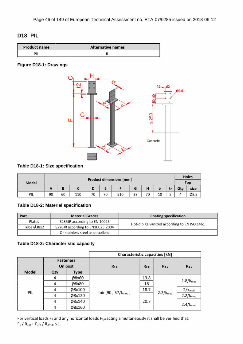
D18: PIL
Product name Alternative names
PIL IL
Figure D18-1: Drawings
Table D18-1: Size specification
Model Product dimensions [mm]
Holes
Top
A B C D E F G H t1 t2 Qty size
PIL 90 60 110 70 70 510 38 70 10 5 4 Ø8.5
Table D18-2: Material specification
Part Material Grades Coating specification
Plates S235JR according to EN 10025 Hot-dip galvanized according to EN ISO 1461
Tube Ø38x2 S220JR according to EN10025:2004
Or stainless steel as described
Table D18-3: Characteristic capacity
Characteristic capacities [kN]
Model
Fasteners
R1.k R2.k R3.k R4.k On post
Qty Type
PIL
4 Ø8x60
min(90 ; 57/kmod )
13.8
2.2/kmod
1.8/kmod 4 Ø8x80 16
4 Ø8x100 18.7 2/kmod
4 Ø8x120
20.7
2.2/kmod
4 Ø8x140 2.4/kmod
4 Ø8x160
For vertical loads F1 and any horizontal loads F3/4 acting simultaneously it shall be verified that: F1 / R1.d + F3/4 / R3/4.d ≤ 1.
Page 47 of 149 of European Technical Assessment no. ETA-07/0285 issued on 2018-06-12
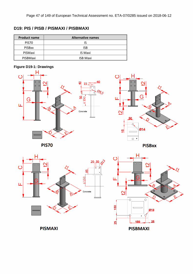
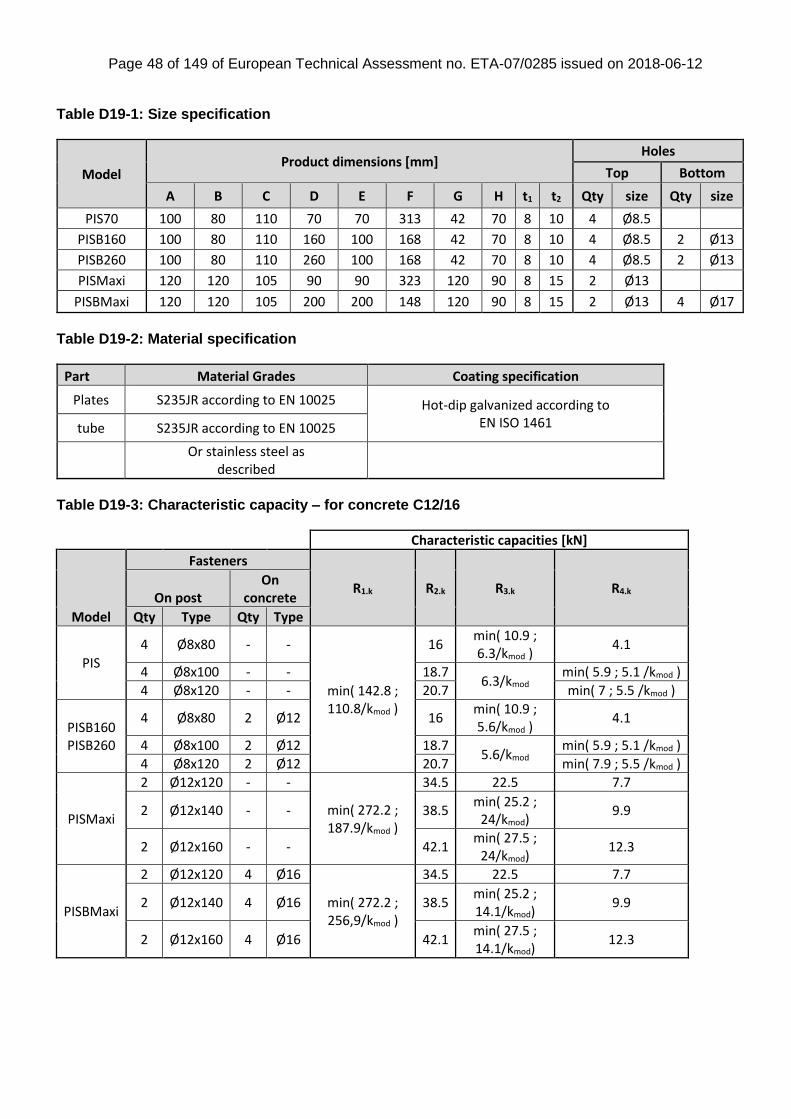
D19: PIS / PISB / PISMAXI / PISBMAXI
Product name Alternative names
PIS70 IS
PISBxx ISB
PISMaxi IS Maxi
PISBMaxi ISB Maxi
Figure D19-1: Drawings
Page 48 of 149 of European Technical Assessment no. ETA-07/0285 issued on 2018-06-12
Table D19-1: Size specification
Model Product dimensions [mm]
Holes
Top Bottom
A B C D E F G H t1 t2 Qty size Qty size
PIS70 100 80 110 70 70 313 42 70 8 10 4 Ø8.5
PISB160 100 80 110 160 100 168 42 70 8 10 4 Ø8.5 2 Ø13
PISB260 100 80 110 260 100 168 42 70 8 10 4 Ø8.5 2 Ø13
PISMaxi 120 120 105 90 90 323 120 90 8 15 2 Ø13
PISBMaxi 120 120 105 200 200 148 120 90 8 15 2 Ø13 4 Ø17
Table D19-2: Material specification
Part Material Grades Coating specification
Plates S235JR according to EN 10025 Hot-dip galvanized according to EN ISO 1461 tube S235JR according to EN 10025
Or stainless steel as
described
Table D19-3: Characteristic capacity – for concrete C12/16
Characteristic capacities [kN]
Model
Fasteners
R1.k R2.k R3.k R4.k On post
On concrete
Qty Type Qty Type
PIS
4 Ø8x80 - -
min( 142.8 ; 110.8/kmod )
16 min( 10.9 ; 6.3/kmod )
4.1
4 Ø8x100 - - 18.7 6.3/kmod
min( 5.9 ; 5.1 /kmod )
4 Ø8x120 - - 20.7 min( 7 ; 5.5 /kmod )
PISB160 PISB260
4 Ø8x80 2 Ø12 16 min( 10.9 ; 5.6/kmod )
4.1
4 Ø8x100 2 Ø12 18.7 5.6/kmod
min( 5.9 ; 5.1 /kmod )
4 Ø8x120 2 Ø12 20.7 min( 7.9 ; 5.5 /kmod )
PISMaxi
2 Ø12x120 - -
min( 272.2 ; 187.9/kmod )
34.5 22.5 7.7
2 Ø12x140 - - 38.5 min( 25.2 ;
24/kmod) 9.9
2 Ø12x160 - - 42.1 min( 27.5 ;
24/kmod) 12.3
PISBMaxi
2 Ø12x120 4 Ø16
min( 272.2 ; 256,9/kmod )
34.5 22.5 7.7
2 Ø12x140 4 Ø16 38.5 min( 25.2 ; 14.1/kmod)
9.9
2 Ø12x160 4 Ø16 42.1 min( 27.5 ; 14.1/kmod)
12.3
Page 49 of 149 of European Technical Assessment no. ETA-07/0285 issued on 2018-06-12
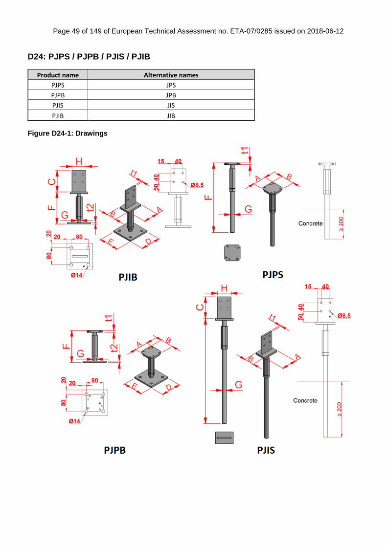
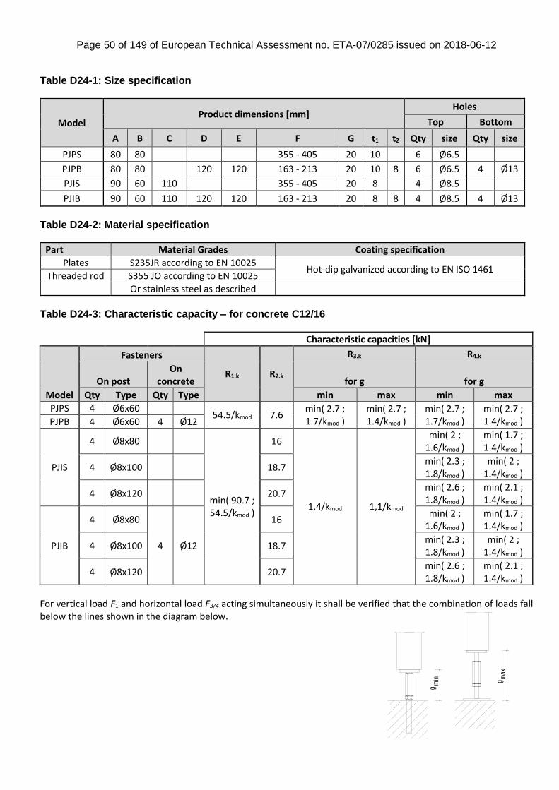
D24: PJPS / PJPB / PJIS / PJIB
Product name Alternative names
PJPS JPS
PJPB JPB
PJIS JIS
PJIB JIB
Figure D24-1: Drawings
Page 50 of 149 of European Technical Assessment no. ETA-07/0285 issued on 2018-06-12
Table D24-1: Size specification
Model Product dimensions [mm]
Holes
Top Bottom
A B C D E F G t1 t2 Qty size Qty size
PJPS 80 80 355 - 405 20 10 6 Ø6.5
PJPB 80 80 120 120 163 - 213 20 10 8 6 Ø6.5 4 Ø13
PJIS 90 60 110 355 - 405 20 8 4 Ø8.5
PJIB 90 60 110 120 120 163 - 213 20 8 8 4 Ø8.5 4 Ø13
Table D24-2: Material specification
Part Material Grades Coating specification
Plates S235JR according to EN 10025 Hot-dip galvanized according to EN ISO 1461
Threaded rod S355 JO according to EN 10025
Or stainless steel as described
Table D24-3: Characteristic capacity – for concrete C12/16
Characteristic capacities [kN]
Model
Fasteners
R1.k R2.k
R3.k R4.k
On post On
concrete for g for g
Qty Type Qty Type min max min max
PJPS 4 Ø6x60 54.5/kmod 7.6
min( 2.7 ; 1.7/kmod )
min( 2.7 ; 1.4/kmod )
min( 2.7 ; 1.7/kmod )
min( 2.7 ; 1.4/kmod ) PJPB 4 Ø6x60 4 Ø12
PJIS
4 Ø8x80
min( 90.7 ; 54.5/kmod )
16
1.4/kmod 1,1/kmod
min( 2 ; 1.6/kmod )
min( 1.7 ; 1.4/kmod )
4 Ø8x100 18.7 min( 2.3 ; 1.8/kmod )
min( 2 ; 1.4/kmod )
4 Ø8x120 20.7 min( 2.6 ; 1.8/kmod )
min( 2.1 ; 1.4/kmod )
PJIB
4 Ø8x80
4 Ø12
16 min( 2 ;
1.6/kmod ) min( 1.7 ; 1.4/kmod )
4 Ø8x100 18.7 min( 2.3 ; 1.8/kmod )
min( 2 ; 1.4/kmod )
4 Ø8x120 20.7 min( 2.6 ; 1.8/kmod )
min( 2.1 ; 1.4/kmod )
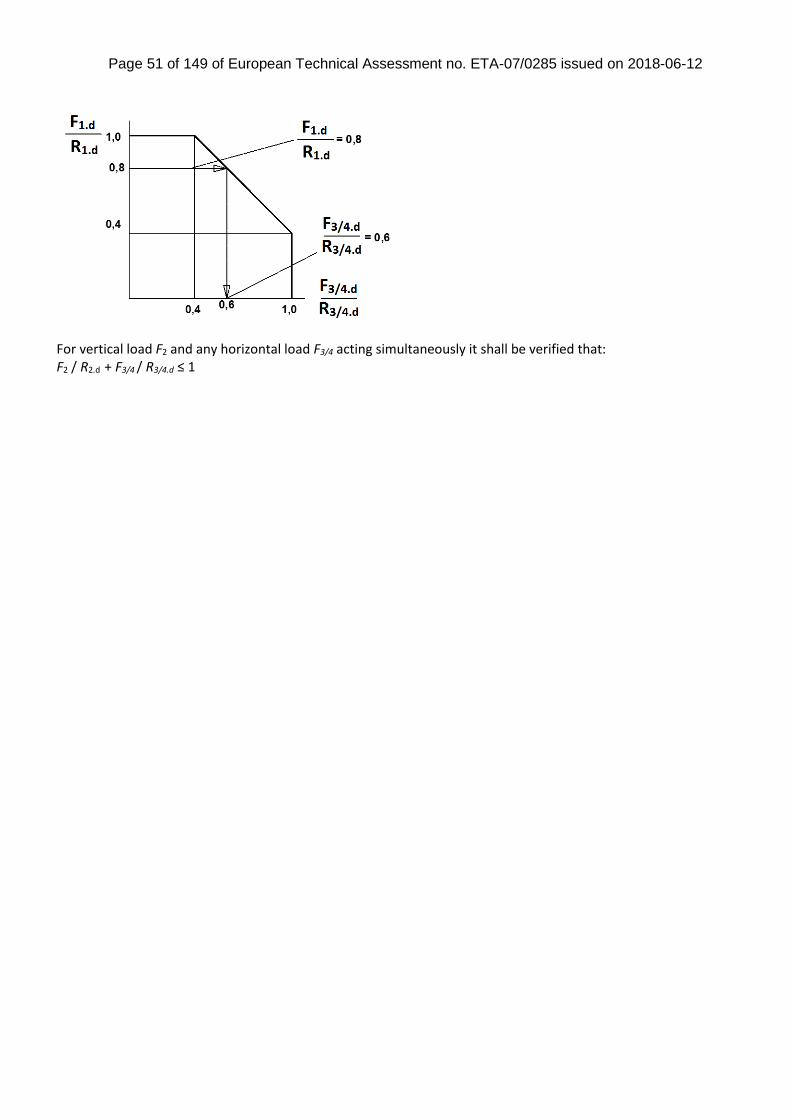
For vertical load F1 and horizontal load F3/4 acting simultaneously it shall be verified that the combination of loads fall below the lines shown in the diagram below.
g
g m
in max
Page 51 of 149 of European Technical Assessment no. ETA-07/0285 issued on 2018-06-12
For vertical load F2 and any horizontal load F3/4 acting simultaneously it shall be verified that: F2 / R2.d + F3/4 / R3/4.d ≤ 1

Page 52 of 149 of European Technical Assessment no. ETA-07/0285 issued on 2018-06-12
D20: PL
Product name Alternative names
PL L
Figure D20-1: Drawings
Table D20-1: Size specification
Model Product dimensions [mm]
Holes
Top
A B C D E F G t1 Qty size Qty size
PL80/70G 80 70 126 70 70 500 38 5 8 Ø5 4 Ø13.5
PL100/70G 100 70 126 70 70 500 38 5 8 Ø5 4 Ø13.5
PL90/90G 90 90 141 70 70 500 38 5 12 Ø5 4 Ø13.5
PL100/90G 100 90 136 70 70 500 38 5 12 Ø5 4 Ø13.5
PL120/90G 120 90 126 70 70 500 38 5 12 Ø5 4 Ø13.5
PL140/90G 140 90 126 70 70 500 38 5 12 Ø5 4 Ø13.5
Table D20-2: Material specification
Part Material Grades Coating specification
Plate S235JR according to EN 10025 Hot-dip galvanized according to EN ISO 1461
Tube Ø38x2 S220JR according to EN10025:2004
Or stainless steel as described
Page 53 of 149 of European Technical Assessment no. ETA-07/0285 issued on 2018-06-12
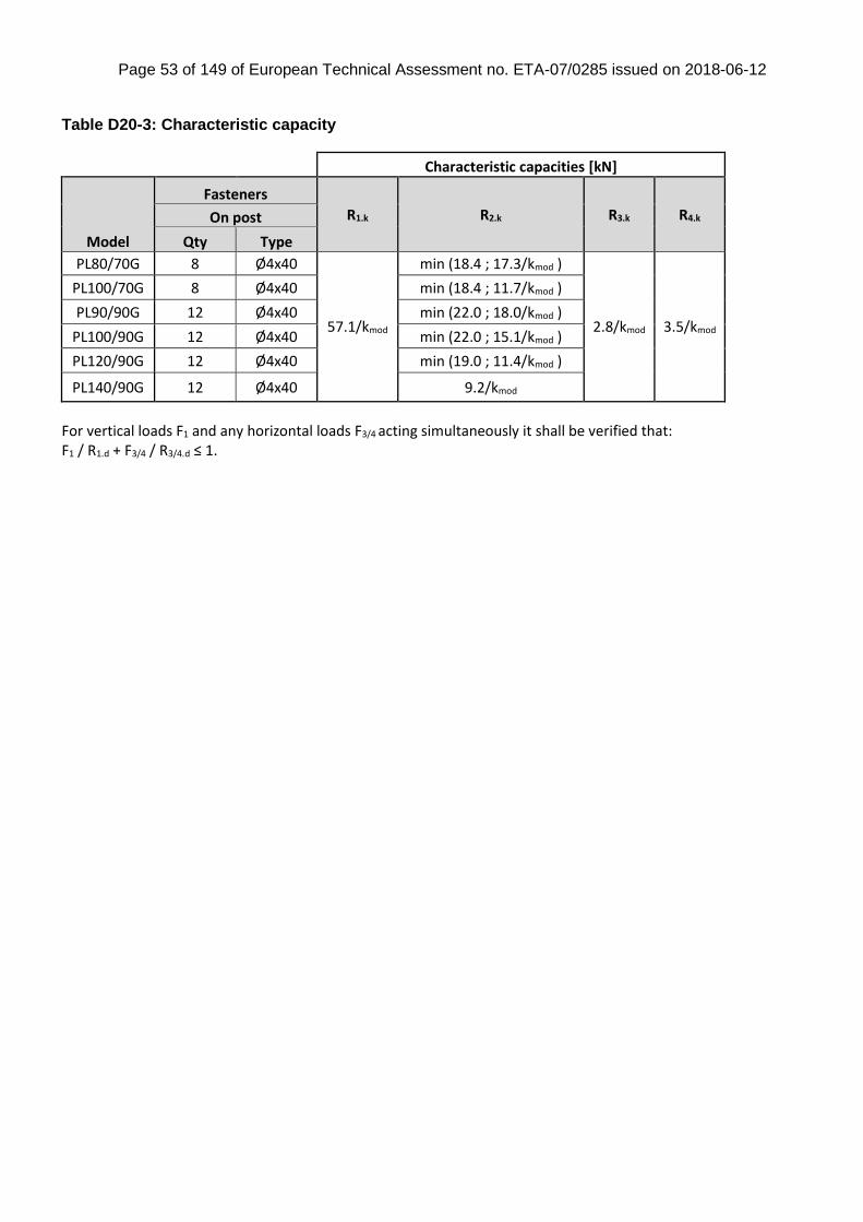
Table D20-3: Characteristic capacity
Characteristic capacities [kN]
Model
Fasteners
R1.k R2.k R3.k R4.k On post
Qty Type
PL80/70G 8 Ø4x40
57.1/kmod
min (18.4 ; 17.3/kmod )
2.8/kmod 3.5/kmod
PL100/70G 8 Ø4x40 min (18.4 ; 11.7/kmod )
PL90/90G 12 Ø4x40 min (22.0 ; 18.0/kmod )
PL100/90G 12 Ø4x40 min (22.0 ; 15.1/kmod )
PL120/90G 12 Ø4x40 min (19.0 ; 11.4/kmod )
PL140/90G 12 Ø4x40 9.2/kmod
For vertical loads F1 and any horizontal loads F3/4 acting simultaneously it shall be verified that: F1 / R1.d + F3/4 / R3/4.d ≤ 1.
Page 54 of 149 of European Technical Assessment no. ETA-07/0285 issued on 2018-06-12
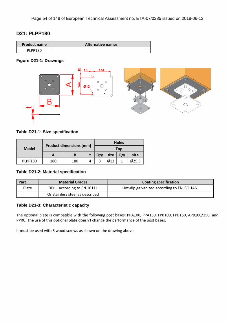
D21: PLPP180
Product name Alternative names
PLPP180 Figure D21-1: Drawings
Table D21-1: Size specification
Model Product dimensions [mm]
Holes
Top
A B t Qty size Qty size
PLPP180 180 180 4 8 Ø12 1 Ø25.5
Table D21-2: Material specification
Part Material Grades Coating specification
Plate DD11 according to EN 10111 Hot-dip galvanized according to EN ISO 1461
Or stainless steel as described
Table D21-3: Characteristic capacity The optional plate is compatible with the following post bases: PPA100, PPA150, FPB100, FPB150, APB100/150, and PPRC. The use of this optional plate doesn’t change the performance of the post bases. It must be used with 8 wood screws as shown on the drawing above
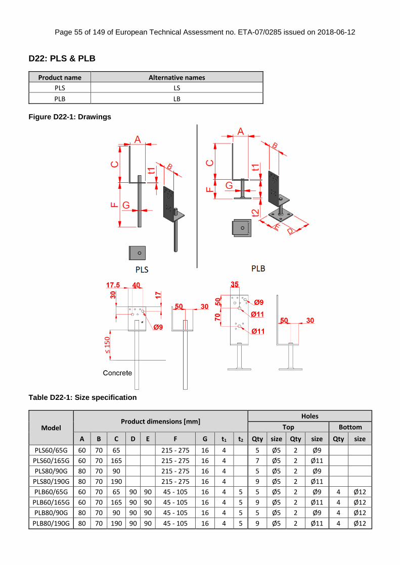
Page 55 of 149 of European Technical Assessment no. ETA-07/0285 issued on 2018-06-12
D22: PLS & PLB
Product name Alternative names
PLS LS
PLB LB
Figure D22-1: Drawings
Table D22-1: Size specification
Model Product dimensions [mm]
Holes
Top Bottom
A B C D E F G t1 t2 Qty size Qty size Qty size
PLS60/65G 60 70 65 215 - 275 16 4 5 Ø5 2 Ø9
PLS60/165G 60 70 165 215 - 275 16 4 7 Ø5 2 Ø11
PLS80/90G 80 70 90 215 - 275 16 4 5 Ø5 2 Ø9
PLS80/190G 80 70 190 215 - 275 16 4 9 Ø5 2 Ø11
PLB60/65G 60 70 65 90 90 45 - 105 16 4 5 5 Ø5 2 Ø9 4 Ø12
PLB60/165G 60 70 165 90 90 45 - 105 16 4 5 9 Ø5 2 Ø11 4 Ø12
PLB80/90G 80 70 90 90 90 45 - 105 16 4 5 5 Ø5 2 Ø9 4 Ø12
PLB80/190G 80 70 190 90 90 45 - 105 16 4 5 9 Ø5 2 Ø11 4 Ø12

Page 56 of 149 of European Technical Assessment no. ETA-07/0285 issued on 2018-06-12
Table D22-2: Material specification
Part Material Grades Coating specification
Plates S235JR according to EN 10025 Hot-dip galvanized according to EN ISO 1461 Threaded
rod Threaded rod: S355 JO according to EN
10025
Or stainless steel as described
Table D22-3: Characteristic capacity
Characteristic capacities [kN]
Model
Fasteners R1.k
R2.k On post Load direction / timber grain
Qty Type Parallel Perpendicular
PLS60/65G PLB60/65G
3 CNA4.0x40
min( 50.8 ; 36.4/kmod) min( 20.1 ; 20.2/kmod)
min( 5.4 ; 3.5/kmod) 2 CSA5.0x35
PLS60/165G PLB60/165G
2 CNA4.0x40 min( 2.8 ; 3/kmod)
1 screw 8x60
PLS80/90G PLB80/90G
3 CNA4.0x40 2.3/kmod
2 CSA5.0x35
PLS80/190G PLB80/190G
2 CNA4.0x40 min( 2.8 ; 2.3/kmod)
1 screw 8x60
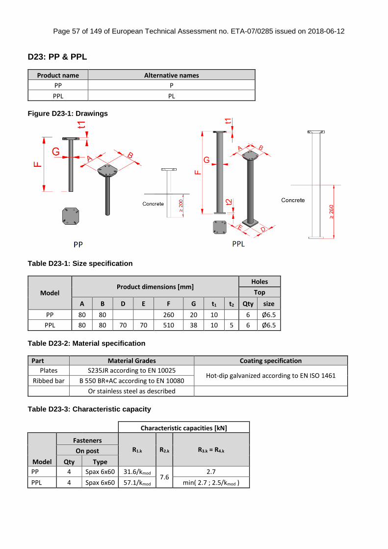
Page 57 of 149 of European Technical Assessment no. ETA-07/0285 issued on 2018-06-12
D23: PP & PPL
Product name Alternative names
PP P
PPL PL
Figure D23-1: Drawings
Table D23-1: Size specification
Model Product dimensions [mm]
Holes
Top
A B D E F G t1 t2 Qty size
PP 80 80 260 20 10 6 Ø6.5
PPL 80 80 70 70 510 38 10 5 6 Ø6.5
Table D23-2: Material specification
Part Material Grades Coating specification
Plates S235JR according to EN 10025 Hot-dip galvanized according to EN ISO 1461
Ribbed bar B 550 BR+AC according to EN 10080
Or stainless steel as described
Table D23-3: Characteristic capacity
Characteristic capacities [kN]
Model
Fasteners
R1.k R2.k R3.k = R4.k On post
Qty Type
PP 4 Spax 6x60 31.6/kmod 7.6
2.7
PPL 4 Spax 6x60 57.1/kmod min( 2.7 ; 2.5/kmod )
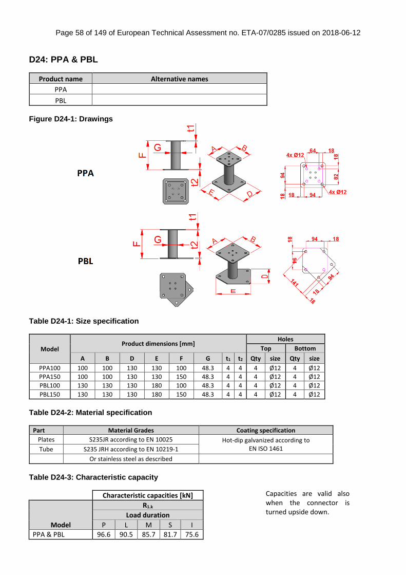
Page 58 of 149 of European Technical Assessment no. ETA-07/0285 issued on 2018-06-12
D24: PPA & PBL
Product name Alternative names
PPA
PBL
Figure D24-1: Drawings
Table D24-1: Size specification
Model Product dimensions [mm]
Holes
Top Bottom
A B D E F G t1 t2 Qty size Qty size
PPA100 100 100 130 130 100 48.3 4 4 4 Ø12 4 Ø12
PPA150 100 100 130 130 150 48.3 4 4 4 Ø12 4 Ø12
PBL100 130 130 130 180 100 48.3 4 4 4 Ø12 4 Ø12
PBL150 130 130 130 180 150 48.3 4 4 4 Ø12 4 Ø12
Table D24-2: Material specification
Part Material Grades Coating specification
Plates S235JR according to EN 10025 Hot-dip galvanized according to EN ISO 1461 Tube S235 JRH according to EN 10219-1
Or stainless steel as described
Table D24-3: Characteristic capacity
Characteristic capacities [kN]
Model
R1.k
Load duration
P L M S I
PPA & PBL 96.6 90.5 85.7 81.7 75.6
Capacities are valid also when the connector is turned upside down.
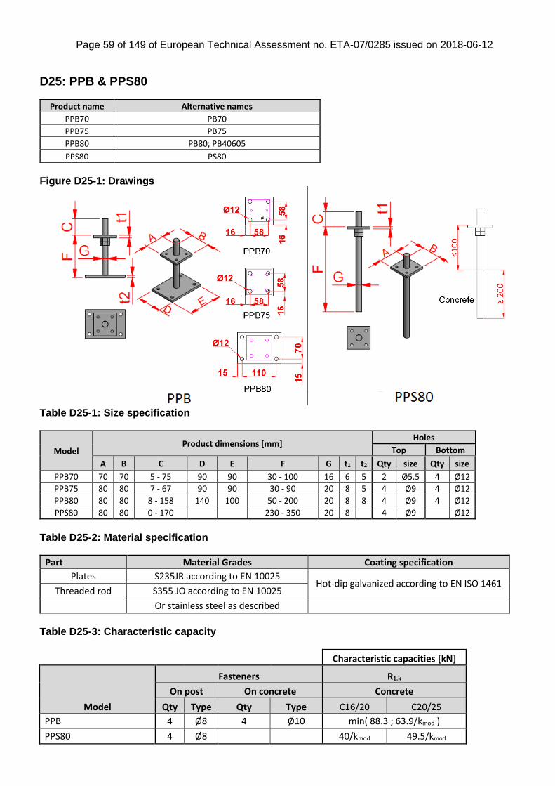
Page 59 of 149 of European Technical Assessment no. ETA-07/0285 issued on 2018-06-12
D25: PPB & PPS80
Product name Alternative names
PPB70 PB70
PPB75 PB75
PPB80 PB80; PB40605
PPS80 PS80
Figure D25-1: Drawings
Table D25-1: Size specification
Model Product dimensions [mm]
Holes
Top Bottom
A B C D E F G t1 t2 Qty size Qty size
PPB70 70 70 5 - 75 90 90 30 - 100 16 6 5 2 Ø5.5 4 Ø12
PPB75 80 80 7 - 67 90 90 30 - 90 20 8 5 4 Ø9 4 Ø12
PPB80 80 80 8 - 158 140 100 50 - 200 20 8 8 4 Ø9 4 Ø12
PPS80 80 80 0 - 170 230 - 350 20 8 4 Ø9 Ø12
Table D25-2: Material specification
Part Material Grades Coating specification
Plates S235JR according to EN 10025 Hot-dip galvanized according to EN ISO 1461
Threaded rod S355 JO according to EN 10025
Or stainless steel as described
Table D25-3: Characteristic capacity
Characteristic capacities [kN]
Model
Fasteners R1.k
On post On concrete Concrete
Qty Type Qty Type C16/20 C20/25
PPB 4 Ø8 4 Ø10 min( 88.3 ; 63.9/kmod )
PPS80 4 Ø8 40/kmod 49.5/kmod

Page 60 of 149 of European Technical Assessment no. ETA-07/0285 issued on 2018-06-12
D26: PPD
Product name Alternative names
PPD D
Figure D26-1: Drawings
Table D26-1: Size specification
Model Product dimensions [mm]
Holes
Top
A B C F G t1 Qty size Qty size
PPD 48 x 40 48 40 121.5 255 16 5 8 Ø5 2 Ø13.5
PPD 50 x 40 50 40 120.5 255 16 5 8 Ø5 2 Ø13.5
PPD 73 x 40 73 40 121.5 255 16 5 8 Ø5 2 Ø13.5
PPD 100 x 40 100 40 120.5 255 16 5 8 Ø5 2 Ø13.5
PPD 98 x 60 98 60 122.5 255 16 5 10 Ø5 2 Ø13.5
PPD 70 x 70 70 70 126.5 255 16 5 10 Ø5 2 Ø13.5
PPD 73 x 70 73 70 125 255 16 5 10 Ø5 2 Ø13.5
PPD 75 x 70 75 70 124 255 16 5 10 Ø5 2 Ø13.5
PPD 80 x 70 80 70 121.5 255 16 5 10 Ø5 2 Ø13.5
PPD 90 x 70 90 70 126.5 255 16 5 10 Ø5 2 Ø13.5
PPD 100 x 70 100 70 121.5 255 16 5 10 Ø5 2 Ø13.5
PPD 90 x 90 90 90 136.5 255 20 5 12 Ø5 4 Ø13.5
PPD 100 x 90 100 90 131.5 255 20 5 12 Ø5 4 Ø13.5
PPD 115 x 90 115 90 124 255 20 5 12 Ø5 4 Ø13.5
PPD 120 x 90 120 90 121.5 255 20 5 12 Ø5 4 Ø13.5
PPD 123 x 90 123 90 120 255 20 5 12 Ø5 4 Ø13.5
PPD 125 x 90 125 90 119 255 20 5 12 Ø5 4 Ø13.5
PPD 140 x 90 140 90 121.5 255 20 5 12 Ø5 4 Ø13.5
PPD 148 x 90 148 90 117.5 255 20 5 12 Ø5 4 Ø13.5
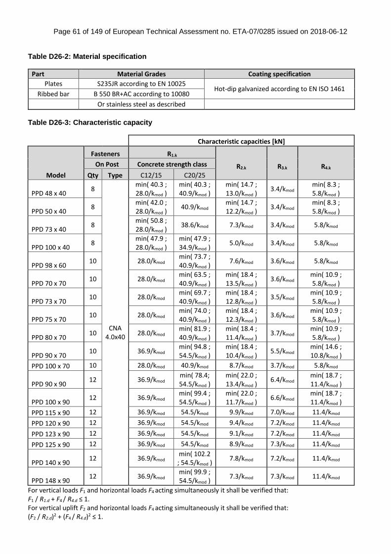
Page 61 of 149 of European Technical Assessment no. ETA-07/0285 issued on 2018-06-12
Table D26-2: Material specification
Part Material Grades Coating specification
Plates S235JR according to EN 10025 Hot-dip galvanized according to EN ISO 1461
Ribbed bar B 550 BR+AC according to 10080
Or stainless steel as described
Table D26-3: Characteristic capacity
Characteristic capacities [kN]
Model
Fasteners R1.k
R2.k
R3.k
R4.k
On Post Concrete strength class
Qty Type C12/15 C20/25
PPD 48 x 40 8
CNA 4.0x40
min( 40.3 ; 28.0/kmod )
min( 40.3 ; 40.9/kmod )
min( 14.7 ; 13.0/kmod )
3.4/kmod min( 8.3 ; 5.8/kmod )
PPD 50 x 40 8
min( 42.0 ; 28.0/kmod )
40.9/kmod min( 14.7 ; 12.2/kmod )
3.4/kmod min( 8.3 ; 5.8/kmod )
PPD 73 x 40 8
min( 50.8 ; 28.0/kmod )
38.6/kmod 7.3/kmod 3.4/kmod 5.8/kmod
PPD 100 x 40 8
min( 47.9 ; 28.0/kmod )
min( 47.9 ; 34.9/kmod )
5.0/kmod 3.4/kmod 5.8/kmod
PPD 98 x 60 10 28.0/kmod
min( 73.7 ; 40.9/kmod )
7.6/kmod 3.6/kmod 5.8/kmod
PPD 70 x 70 10 28.0/kmod
min( 63.5 ; 40.9/kmod )
min( 18.4 ; 13.5/kmod )
3.6/kmod min( 10.9 ; 5.8/kmod )
PPD 73 x 70 10 28.0/kmod
min( 69.7 ; 40.9/kmod )
min( 18.4 ; 12.8/kmod )
3.5/kmod min( 10.9 ; 5.8/kmod )
PPD 75 x 70 10 28.0/kmod
min( 74.0 ; 40.9/kmod )
min( 18.4 ; 12.3/kmod )
3.6/kmod min( 10.9 ; 5.8/kmod )
PPD 80 x 70 10 28.0/kmod
min( 81.9 ; 40.9/kmod )
min( 18.4 ; 11.4/kmod )
3.7/kmod min( 10.9 ; 5.8/kmod )
PPD 90 x 70 10 36.9/kmod
min( 94.8 ; 54.5/kmod )
min( 18.4 ; 10.4/kmod )
5.5/kmod min( 14.6 ; 10.8/kmod )
PPD 100 x 70 10 28.0/kmod 40.9/kmod 8.7/kmod 3.7/kmod 5.8/kmod
PPD 90 x 90 12 36.9/kmod
min( 78.4; 54.5/kmod )
min( 22.0 ; 13.4/kmod )
6.4/kmod min( 18.7 ; 11.4/kmod )
PPD 100 x 90 12 36.9/kmod
min( 99.4 ; 54.5/kmod )
min( 22.0 ; 11.7/kmod )
6.6/kmod min( 18.7 ; 11.4/kmod )
PPD 115 x 90 12 36.9/kmod 54.5/kmod 9.9/kmod 7.0/kmod 11.4/kmod
PPD 120 x 90 12 36.9/kmod 54.5/kmod 9.4/kmod 7.2/kmod 11.4/kmod
PPD 123 x 90 12 36.9/kmod 54.5/kmod 9.1/kmod 7.2/kmod 11.4/kmod
PPD 125 x 90 12 36.9/kmod 54.5/kmod 8.9/kmod 7.3/kmod 11.4/kmod
PPD 140 x 90 12 36.9/kmod
min( 102.2 ; 54.5/kmod )
7.8/kmod 7.2/kmod 11.4/kmod
PPD 148 x 90 12 36.9/kmod
min( 99.9 ; 54.5/kmod )
7.3/kmod 7.3/kmod 11.4/kmod
For vertical loads F1 and horizontal loads F4 acting simultaneously it shall be verified that: F1 / R1.d + F4 / R4.d ≤ 1. For vertical uplift F2 and horizontal loads F4 acting simultaneously it shall be verified that: (F2 / R2.d)2 + (F4 / R4.d)2 ≤ 1.
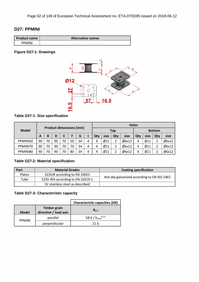
Page 62 of 149 of European Technical Assessment no. ETA-07/0285 issued on 2018-06-12
D27: PPMINI
Product name Alternative names
PPMINI
Figure D27-1: Drawings
Table D27-1: Size specification
Model Product dimensions [mm]
Holes
Top Bottom
A B D E F G t Qty size Qty size Qty size Qty size
PPMINI50 90 70 90 70 50 34 4 4 Ø11 2 Ø6x12 4 Ø11 2 Ø6x12
PPMINI70 90 70 90 70 70 34 4 4 Ø11 2 Ø6x12 4 Ø11 2 Ø6x12
PPMINI80 90 70 90 70 80 34 4 4 Ø11 2 Ø6x12 4 Ø11 2 Ø6x12
Table D27-2: Material specification
Part Material Grades Coating specification
Plates S235JR according to EN 10025 Hot-dip galvanized according to EN ISO 1461
Tube S235 JRH according to EN 10219-1
Or stainless steel as described
Table D27-3: Characteristic capacity
Characteristic capacities [kN]
Model Timber grain
direction / load axis R1.k
PPMINI parallel 58.6 / kmod
0.37
perpendicular 21.6
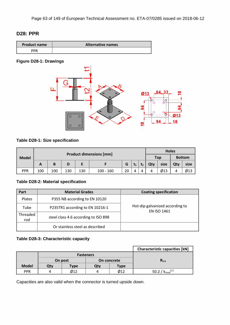
Page 63 of 149 of European Technical Assessment no. ETA-07/0285 issued on 2018-06-12
D28: PPR
Product name Alternative names
PPR
Figure D28-1: Drawings
Table D28-1: Size specification
Model Product dimensions [mm]
Holes
Top Bottom
A B D E F G t1 t2 Qty size Qty size
PPR 100 100 130 130 100 - 160 20 4 4 4 Ø13 4 Ø13
Table D28-2: Material specification
Part Material Grades Coating specification
Plates P355 NB according to EN 10120
Hot-dip galvanized according to EN ISO 1461
Tube P235TR1 according to EN 10216-1
Threaded rod
steel class 4.6 according to ISO 898
Or stainless steel as described
Table D28-3: Characteristic capacity
Characteristic capacities [kN]
Model
Fasteners
R1.k On post On concrete
Qty Type Qty Type
PPR 4 Ø12 4 Ø12 50.2 / kmod0.5
Capacities are also valid when the connector is turned upside down.
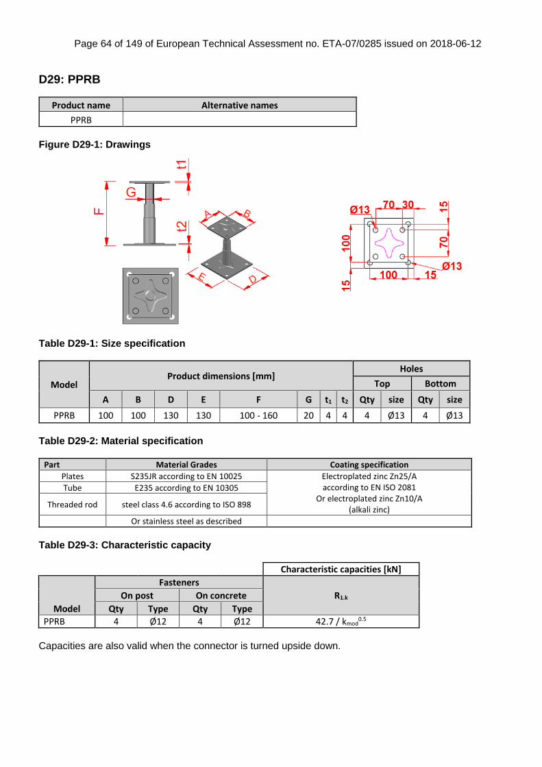
Page 64 of 149 of European Technical Assessment no. ETA-07/0285 issued on 2018-06-12
D29: PPRB
Product name Alternative names
PPRB
Figure D29-1: Drawings
Table D29-1: Size specification
Model Product dimensions [mm]
Holes
Top Bottom
A B D E F G t1 t2 Qty size Qty size
PPRB 100 100 130 130 100 - 160 20 4 4 4 Ø13 4 Ø13
Table D29-2: Material specification
Part Material Grades Coating specification
Plates S235JR according to EN 10025 Electroplated zinc Zn25/A according to EN ISO 2081
Or electroplated zinc Zn10/A (alkali zinc)
Tube E235 according to EN 10305
Threaded rod steel class 4.6 according to ISO 898
Or stainless steel as described
Table D29-3: Characteristic capacity
Characteristic capacities [kN]
Model
Fasteners
R1.k On post On concrete
Qty Type Qty Type
PPRB 4 Ø12 4 Ø12 42.7 / kmod0.5
Capacities are also valid when the connector is turned upside down.
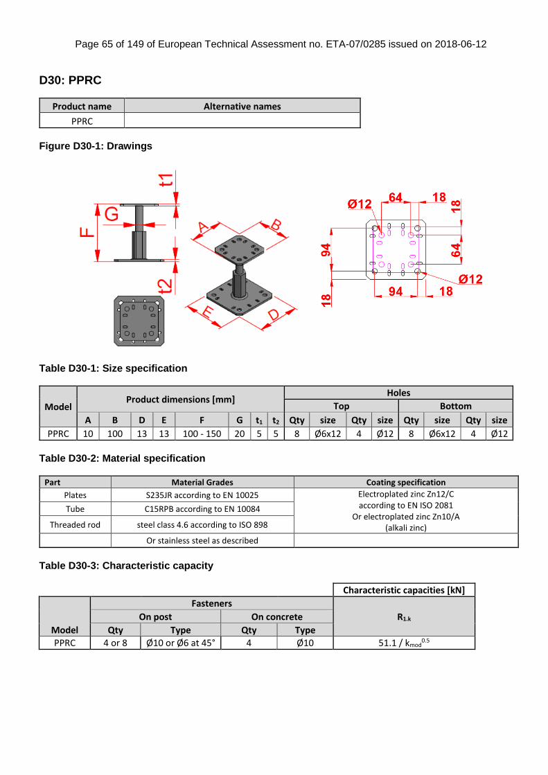
Page 65 of 149 of European Technical Assessment no. ETA-07/0285 issued on 2018-06-12
D30: PPRC
Product name Alternative names
PPRC
Figure D30-1: Drawings
Table D30-1: Size specification
Model Product dimensions [mm]
Holes
Top Bottom
A B D E F G t1 t2 Qty size Qty size Qty size Qty size
PPRC 10 100 13 13 100 - 150 20 5 5 8 Ø6x12 4 Ø12 8 Ø6x12 4 Ø12
Table D30-2: Material specification
Part Material Grades Coating specification
Plates S235JR according to EN 10025 Electroplated zinc Zn12/C according to EN ISO 2081
Or electroplated zinc Zn10/A (alkali zinc)
Tube C15RPB according to EN 10084
Threaded rod steel class 4.6 according to ISO 898
Or stainless steel as described
Table D30-3: Characteristic capacity
Characteristic capacities [kN]
Model
Fasteners
R1.k On post On concrete
Qty Type Qty Type
PPRC 4 or 8 Ø10 or Ø6 at 45° 4 Ø10 51.1 / kmod0.5
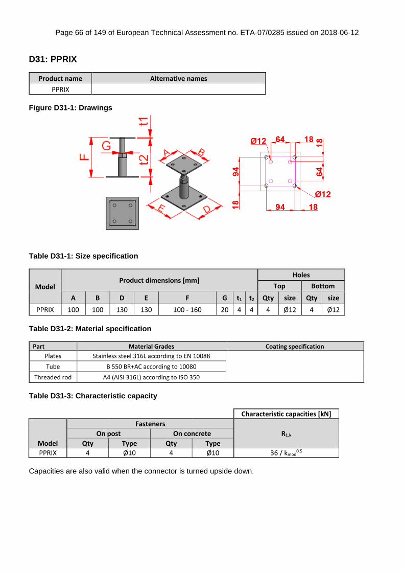
Page 66 of 149 of European Technical Assessment no. ETA-07/0285 issued on 2018-06-12
D31: PPRIX
Product name Alternative names
PPRIX
Figure D31-1: Drawings
Table D31-1: Size specification
Model Product dimensions [mm]
Holes
Top Bottom
A B D E F G t1 t2 Qty size Qty size
PPRIX 100 100 130 130 100 - 160 20 4 4 4 Ø12 4 Ø12
Table D31-2: Material specification
Part Material Grades Coating specification
Plates Stainless steel 316L according to EN 10088
Tube B 550 BR+AC according to 10080
Threaded rod A4 (AISI 316L) according to ISO 350
Table D31-3: Characteristic capacity
Characteristic capacities [kN]
Model
Fasteners
R1.k On post On concrete
Qty Type Qty Type
PPRIX 4 Ø10 4 Ø10 36 / kmod0.5
Capacities are also valid when the connector is turned upside down.
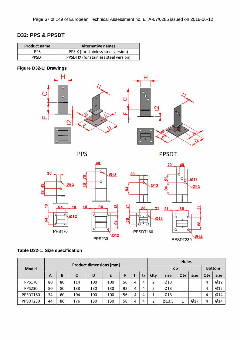
Page 67 of 149 of European Technical Assessment no. ETA-07/0285 issued on 2018-06-12
D32: PPS & PPSDT
Product name Alternative names
PPS PPSIX (for stainless steel version)
PPSDT PPSDTIX (for stainless steel version)
Figure D32-1: Drawings
Table D32-1: Size specification
Model Product dimensions [mm]
Holes
Top Bottom
A B C D E F t1 t2 Qty size Qty size Qty size
PPS170 80 80 114 100 100 56 4 4 2 Ø13 4 Ø12
PPS230 80 80 138 130 130 92 4 4 2 Ø13 4 Ø12
PPSDT160 34 60 104 100 100 56 4 4 1 Ø13 4 Ø14
PPSDT230 44 80 176 130 130 58 4 4 2 Ø13.5 1 Ø17 4 Ø14
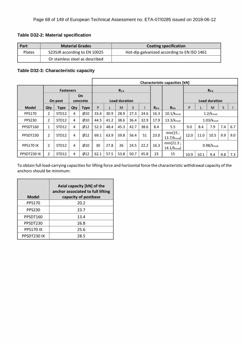
Page 68 of 149 of European Technical Assessment no. ETA-07/0285 issued on 2018-06-12
Table D32-2: Material specification
Part Material Grades Coating specification
Plates S235JR according to EN 10025 Hot-dip galvanized according to EN ISO 1461
Or stainless steel as described
Table D32-3: Characteristic capacity
Characteristic capacities [kN]
Model
Fasteners R1.k
R2.k R3.k
R4.k
On post On
concrete Load duration Load duration
Qty Type Qty Type P L M S I P L M S I
PPS170 2 STD12 4 Ø10 33.4 30.9 28.9 27.3 24.6 16.3 10.1/kmod 1.2/kmod
PPS230 2 STD12 4 Ø10 44.5 41.2 38.6 36.4 32.9 17.9 13.3/kmod 1.03/kmod
PPSDT160 1 STD12 4 Ø12 52.3 48.4 45.3 42.7 38.6 8.4 5.5 9.0 8.4 7.9 7.4 6.7
PPSDT230 2 STD12 4 Ø12 69.1 63.9 59.8 56.4 51 23.0 min(15 ;
13.7/kmod) 12.0 11.0 10.5 9.9 9.0
PPS170 IX 2 STD12 4 Ø10 30 27.8 26 24.5 22.2 16.3 min(21.3 ; 14.1/kmod)
0.98/kmod
PPSDT230 IX 2 STD12 4 Ø12 62.1 57.5 53.8 50.7 45.8 23 15 10.9 10.1 9.4 9.8 7.3
To obtain full load-carrying capacities for lifting force and horizontal force the characteristic withdrawal capacity of the anchors should be minimum:
Model
Axial capacity [kN] of the anchor associated to full lifting
capacity of postbase
PPS170 20.2
PPS230 23.7
PPSDT160 13.4
PPSDT230 26.8
PPS170 IX 25.6
PPSDT230 IX 28.5
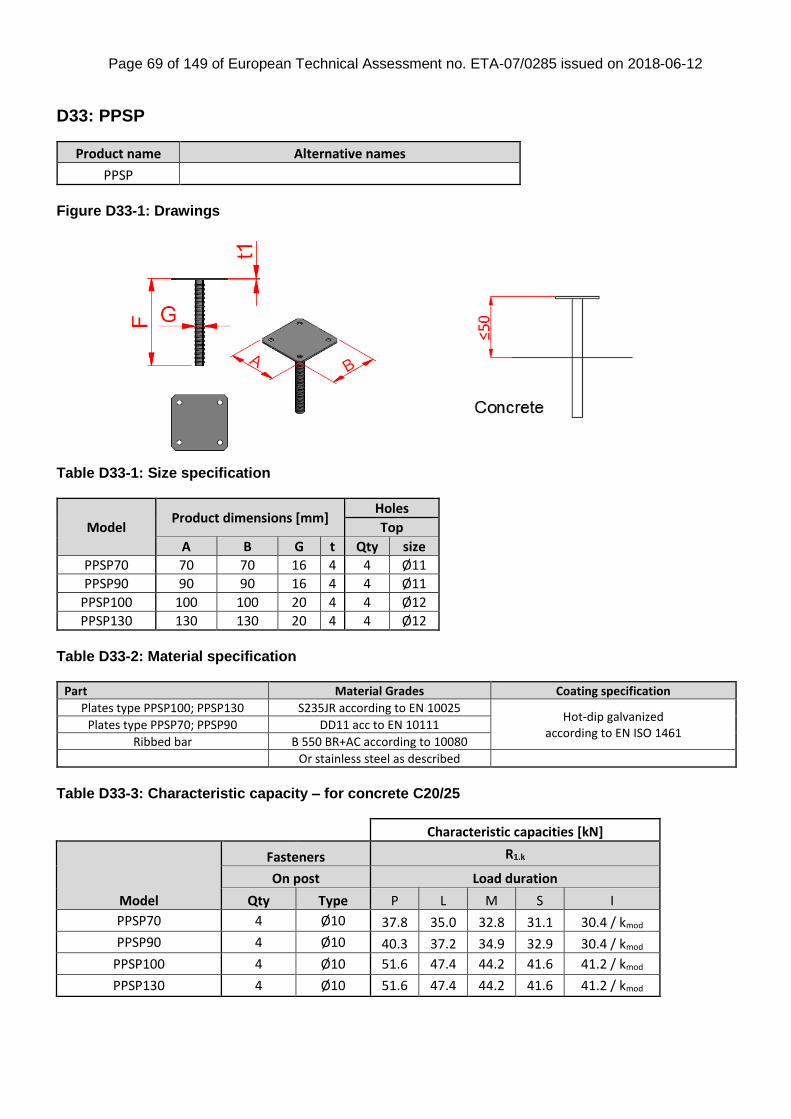
Page 69 of 149 of European Technical Assessment no. ETA-07/0285 issued on 2018-06-12
D33: PPSP
Product name Alternative names
PPSP
Figure D33-1: Drawings
Table D33-1: Size specification
Model Product dimensions [mm]
Holes
Top
A B G t Qty size
PPSP70 70 70 16 4 4 Ø11
PPSP90 90 90 16 4 4 Ø11
PPSP100 100 100 20 4 4 Ø12
PPSP130 130 130 20 4 4 Ø12
Table D33-2: Material specification
Part Material Grades Coating specification
Plates type PPSP100; PPSP130 S235JR according to EN 10025 Hot-dip galvanized
according to EN ISO 1461 Plates type PPSP70; PPSP90 DD11 acc to EN 10111
Ribbed bar B 550 BR+AC according to 10080
Or stainless steel as described
Table D33-3: Characteristic capacity – for concrete C20/25
Characteristic capacities [kN]
Model
Fasteners R1.k
On post Load duration
Qty Type P L M S I
PPSP70 4 Ø10 37.8 35.0 32.8 31.1 30.4 / kmod
PPSP90 4 Ø10 40.3 37.2 34.9 32.9 30.4 / kmod
PPSP100 4 Ø10 51.6 47.4 44.2 41.6 41.2 / kmod
PPSP130 4 Ø10 51.6 47.4 44.2 41.6 41.2 / kmod
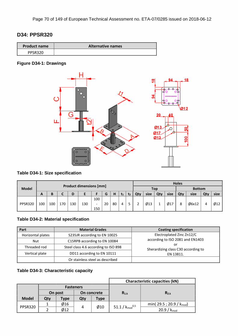
Page 70 of 149 of European Technical Assessment no. ETA-07/0285 issued on 2018-06-12
D34: PPSR320
Product name Alternative names
PPSR320
Figure D34-1: Drawings
Table D34-1: Size specification
Model Product dimensions [mm]
Holes
Top Bottom
A B C D E F G H t1 t2 Qty size Qty size Qty size Qty size
PPSR320 100 100 170 130 130 100
- 150
20 80 4 5 2 Ø13 1 Ø17 8 Ø6x12 4 Ø12
Table D34-2: Material specification
Part Material Grades Coating specification
Horizontal plates S235JR according to EN 10025 Electroplated Zinc Zn12/C according to ISO 2081 and EN1403
or Sherardizing class C30 according to
EN 13811.
Nut C15RPB according to EN 10084
Threaded rod Steel class 4.6 according to ISO 898
Vertical plate DD11 according to EN 10111
Or stainless steel as described
Table D34-3: Characteristic capacity
Characteristic capacities (kN)
Model
Fasteners
R1.k R2.k On post On concrete
Qty Type Qty Type
PPSR320 1 Ø16
4 Ø10 51.1 / kmod0,5
min( 29.5 ; 20.9 / kmod)
2 Ø12 20.9 / kmod

Page 71 of 149 of European Technical Assessment no. ETA-07/0285 issued on 2018-06-12
D35: PPUP
Product name Alternative names
PPUP
Figure D35-1: Drawings
Table D35-1: Size specification
Model Product dimensions [mm]
Holes
Top Bottom
A B C D E F G t1 t2 Qty size Qty size Qty size
PPUP70 70 70 126.5 100 100 100 48.3 4 4 10 Ø5 2 Ø13.5 4 Ø12
PPUP90 90 70 121.5 100 100 100 48.3 4 4 10 Ø5 2 Ø13.5 4 Ø12
Table D35-2: Material specification
Part Material Grades Coating specification
Plates S235JR according to EN 10025 Hot-dip galvanized according to EN ISO 1461 Tube S235 JRH according to EN 10219-1
Or stainless steel as described
Table D35-3: Characteristic capacity
Characteristic capacities [kN]
Model
Fasteners
R1.k R2.k R3.k R4.k On post On concrete
Qty Type Qty Type
PPUP70 10 CNA4,0x40 4 Ø10 92.2 17.8 10.7 8.2 / (kmod0.5)
PPUP90 10 CNA4,0x50 4 Ø10 min( 121.5; 102.8/kmod ) 21.9 min( 13.1 ; 14.1/kmod ) 10.6 / (kmod0.5)
To obtain full load-carrying capacities for lifting force and horizontal force, the characteristic withdrawal capacity of the anchors should be minimum: 14.9 kN for PPUP70 and 18.8 kN for PPUP90.

Page 72 of 149 of European Technical Assessment no. ETA-07/0285 issued on 2018-06-12
D36: PU / EMBU
Product name Alternative names
PUxx EMBU
xx: width of PU Figure D36-1: Drawings
Table D36-1: Size specification
Model Product dimensions [mm]
Holes
Top Bottom
A B C F t1 Qty size Qty size Qty size
PU70-B 71 70 131 24 4 10 Ø5 4 Ø9 1 Ø17x20
PU80-B 81 70 126 24 4 10 Ø5 4 Ø9 1 Ø17x20
PU90-B 91 70 131 24 4 10 Ø5 4 Ø9 2 Ø9 1 Ø17x20
PU100-B 101 70 126 24 4 10 Ø5 4 Ø9 2 Ø9 1 Ø17x20
PU120-B 121 70 116 24 4 10 Ø5 4 Ø9 2 Ø9 1 Ø17x20
PU140-B 141 70 106 24 4 10 Ø5 4 Ø9 2 Ø9 1 Ø17x20
Table D36-2: Material specification
Part Material Grades Coating specification
Plates S235JR according to EN 10025 Hot dip galvanized according to EN ISO 1461
Or stainless steel as described
Table D36-3: Characteristic capacity
Characteristic capacities [kN]
Model
Fasteners R1.k R2.k On post On concrete
Qty Type Qty Type
PU70-B n CNA4,0 1 Ø16
max( 19.1 ; n x Rlat.k )
min( n x Rlat.k ; 14.1/kmod )
PU80-B n CNA4,0 1 Ø16 min( n x Rlat.k ; 11.7/kmod )
PU90-B n CNA4,0 1 Ø16 min( n x Rlat.k ; 10.0/kmod )
PU100-B n CNA4,0 1 Ø16 min( n x Rlat.k ; 8.76/kmod )
PU120-B n CNA4,0 1 Ø16 min( n x Rlat.k ; 6.99/kmod )
PU140-B n CNA4,0 1 Ø16 min( n x Rlat.k ; 5.82/kmod )
n = total number of nails. If the number of nails on each side is different, n is twice the number of nails in the side where the number is the minimum.
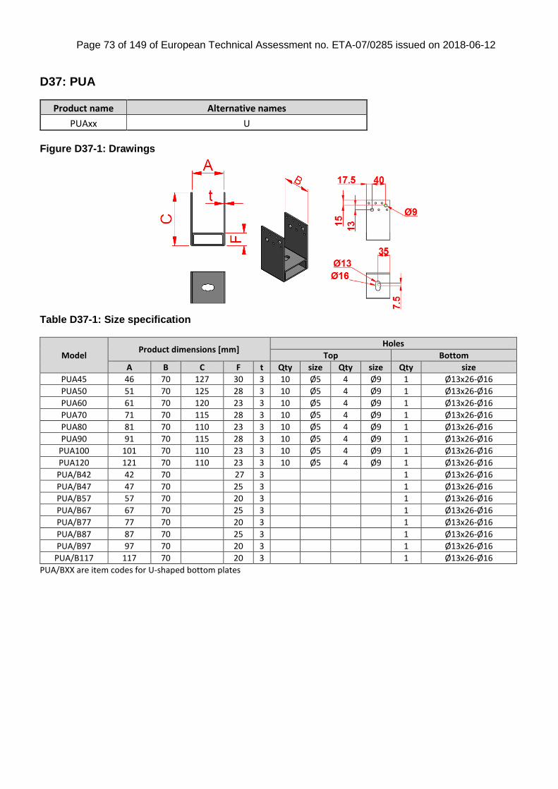
Page 73 of 149 of European Technical Assessment no. ETA-07/0285 issued on 2018-06-12
D37: PUA
Product name Alternative names
PUAxx U
Figure D37-1: Drawings
Table D37-1: Size specification
Model Product dimensions [mm]
Holes
Top Bottom
A B C F t Qty size Qty size Qty size
PUA45 46 70 127 30 3 10 Ø5 4 Ø9 1 Ø13x26-Ø16
PUA50 51 70 125 28 3 10 Ø5 4 Ø9 1 Ø13x26-Ø16
PUA60 61 70 120 23 3 10 Ø5 4 Ø9 1 Ø13x26-Ø16
PUA70 71 70 115 28 3 10 Ø5 4 Ø9 1 Ø13x26-Ø16
PUA80 81 70 110 23 3 10 Ø5 4 Ø9 1 Ø13x26-Ø16
PUA90 91 70 115 28 3 10 Ø5 4 Ø9 1 Ø13x26-Ø16
PUA100 101 70 110 23 3 10 Ø5 4 Ø9 1 Ø13x26-Ø16
PUA120 121 70 110 23 3 10 Ø5 4 Ø9 1 Ø13x26-Ø16
PUA/B42 42 70 27 3 1 Ø13x26-Ø16
PUA/B47 47 70 25 3 1 Ø13x26-Ø16
PUA/B57 57 70 20 3 1 Ø13x26-Ø16
PUA/B67 67 70 25 3 1 Ø13x26-Ø16
PUA/B77 77 70 20 3 1 Ø13x26-Ø16
PUA/B87 87 70 25 3 1 Ø13x26-Ø16
PUA/B97 97 70 20 3 1 Ø13x26-Ø16
PUA/B117 117 70 20 3 1 Ø13x26-Ø16
PUA/BXX are item codes for U-shaped bottom plates
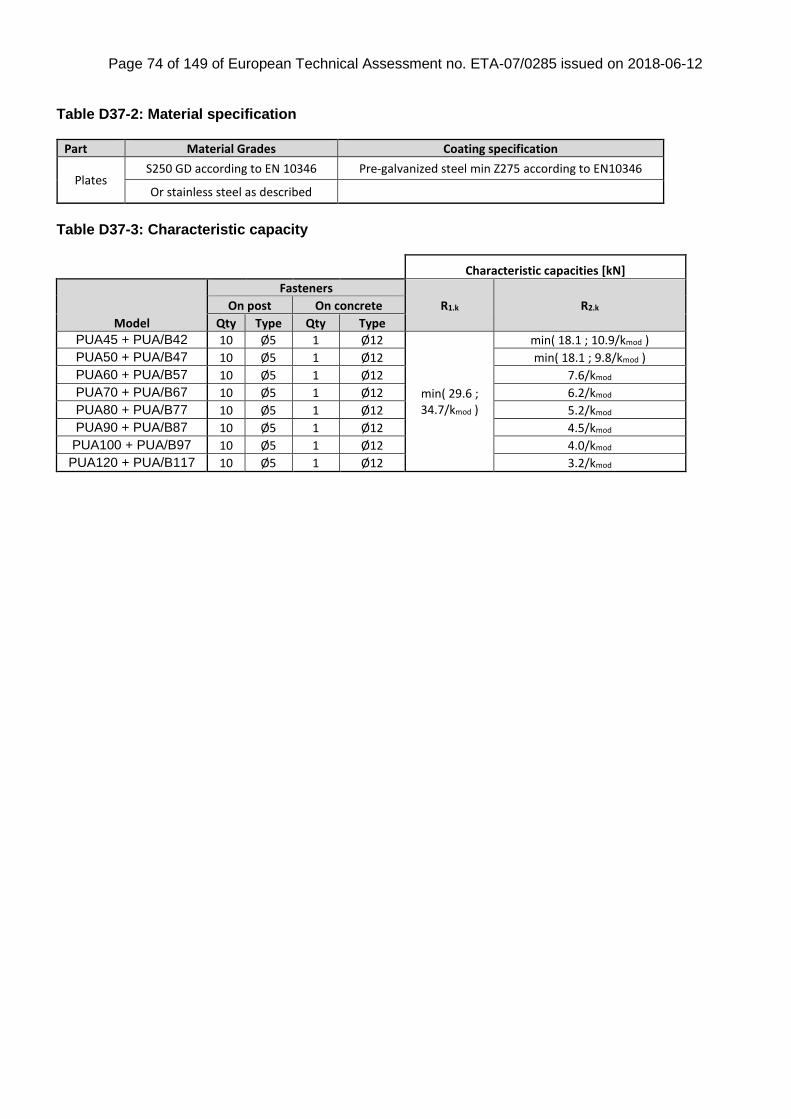
Page 74 of 149 of European Technical Assessment no. ETA-07/0285 issued on 2018-06-12
Table D37-2: Material specification
Part Material Grades Coating specification
Plates S250 GD according to EN 10346 Pre-galvanized steel min Z275 according to EN10346
Or stainless steel as described
Table D37-3: Characteristic capacity
Characteristic capacities [kN]
Model
Fasteners
R1.k R2.k On post On concrete
Qty Type Qty Type
PUA45 + PUA/B42 10 Ø5 1 Ø12
min( 29.6 ; 34.7/kmod )
min( 18.1 ; 10.9/kmod )
PUA50 + PUA/B47 10 Ø5 1 Ø12 min( 18.1 ; 9.8/kmod )
PUA60 + PUA/B57 10 Ø5 1 Ø12 7.6/kmod
PUA70 + PUA/B67 10 Ø5 1 Ø12 6.2/kmod
PUA80 + PUA/B77 10 Ø5 1 Ø12 5.2/kmod
PUA90 + PUA/B87 10 Ø5 1 Ø12 4.5/kmod
PUA100 + PUA/B97 10 Ø5 1 Ø12 4.0/kmod
PUA120 + PUA/B117 10 Ø5 1 Ø12 3.2/kmod
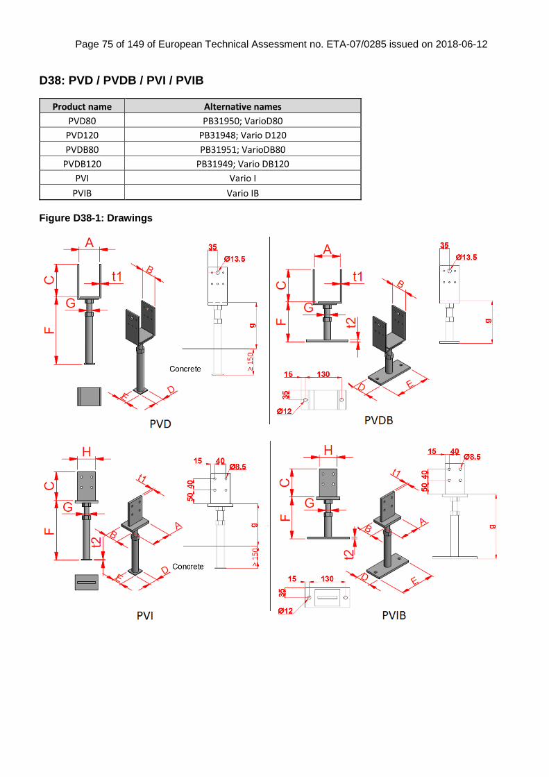
Page 75 of 149 of European Technical Assessment no. ETA-07/0285 issued on 2018-06-12
D38: PVD / PVDB / PVI / PVIB
Product name Alternative names
PVD80 PB31950; VarioD80
PVD120 PB31948; Vario D120
PVDB80 PB31951; VarioDB80
PVDB120 PB31949; Vario DB120
PVI Vario I
PVIB Vario IB
Figure D38-1: Drawings
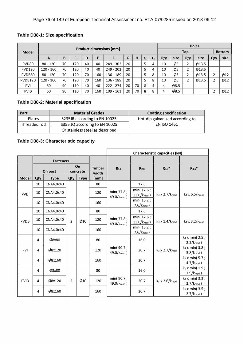
Page 76 of 149 of European Technical Assessment no. ETA-07/0285 issued on 2018-06-12
Table D38-1: Size specification
Model Product dimensions [mm]
Holes
Top Bottom
A B C D E F G H t1 t2 Qty size Qty size Qty size
PVD80 80 - 120 70 120 40 40 249 - 302 20 5 4 10 Ø5 2 Ø13.5
PVD120 120 - 160 70 120 40 40 249 - 202 20 5 4 10 Ø5 2 Ø13.5
PVDB80 80 - 120 70 120 70 160 136 - 189 20 5 8 10 Ø5 2 Ø13.5 2 Ø12
PVDB120 120 - 160 70 120 70 160 136 - 189 20 5 8 10 Ø5 2 Ø13.5 2 Ø12
PVI 60 90 110 40 40 222 - 274 20 70 8 4 4 Ø8.5
PVIB 60 90 110 70 160 109 - 161 20 70 8 8 4 Ø8.5 2 Ø12
Table D38-2: Material specification
Part Material Grades Coating specification
Plates S235JR according to EN 10025 Hot-dip galvanized according to EN ISO 1461 Threaded rod S355 JO according to EN 10025
Or stainless steel as described
Table D38-3: Characteristic capacity
Characteristic capacities (kN)
Model
Fasteners
Timber width [mm]
R1.k R2.k R3.k* R4.k* On post
On concrete
Qty Type Qty Type
PVD
10 CNA4,0x40
80
min( 77.8 ; 49.0/kmod )
17.6
k3 x 2.7/kmod k4 x 6.5/kmod 10 CNA4,0x40 120 min( 17.6 ; 11.6/kmod )
10 CNA4,0x40 160 min( 15.2 ; 7.6/kmod )
PVDB
10 CNA4,0x40
2 Ø10
80
min( 77.8 ; 49.0/kmod )
17.6
k3 x 1.4/kmod k4 x 3.2/kmod 10 CNA4,0x40 120 min( 17.6 ; 11.6/kmod )
10 CNA4,0x40 160 min( 15.2 ; 7.6/kmod )
PVI
4 Ø8x80
80
min( 90.7 ; 49.0/kmod )
16.0
k3 x 2.7/kmod
k4 x min( 2.5 ; 2.2/kmod )
4 Ø8x120 120 20.7 k4 x min( 3.8 ;
3.8/kmod )
4 Ø8x160 160 20.7 k4 x min( 5.7 ;
4.7/kmod )
PVIB
4 Ø8x80
2 Ø10
80
min( 90.7 ; 49.0/kmod )
16.0
k3 x 2.6/kmod
k4 x min( 1.9 ; 1.9/kmod )
4 Ø8x120 120 20.7 k4 x min( 3.3 ;
2.7/kmod )
4 Ø8x160 160 20.7 k4 x min( 3.5 ;
2.7/kmod )
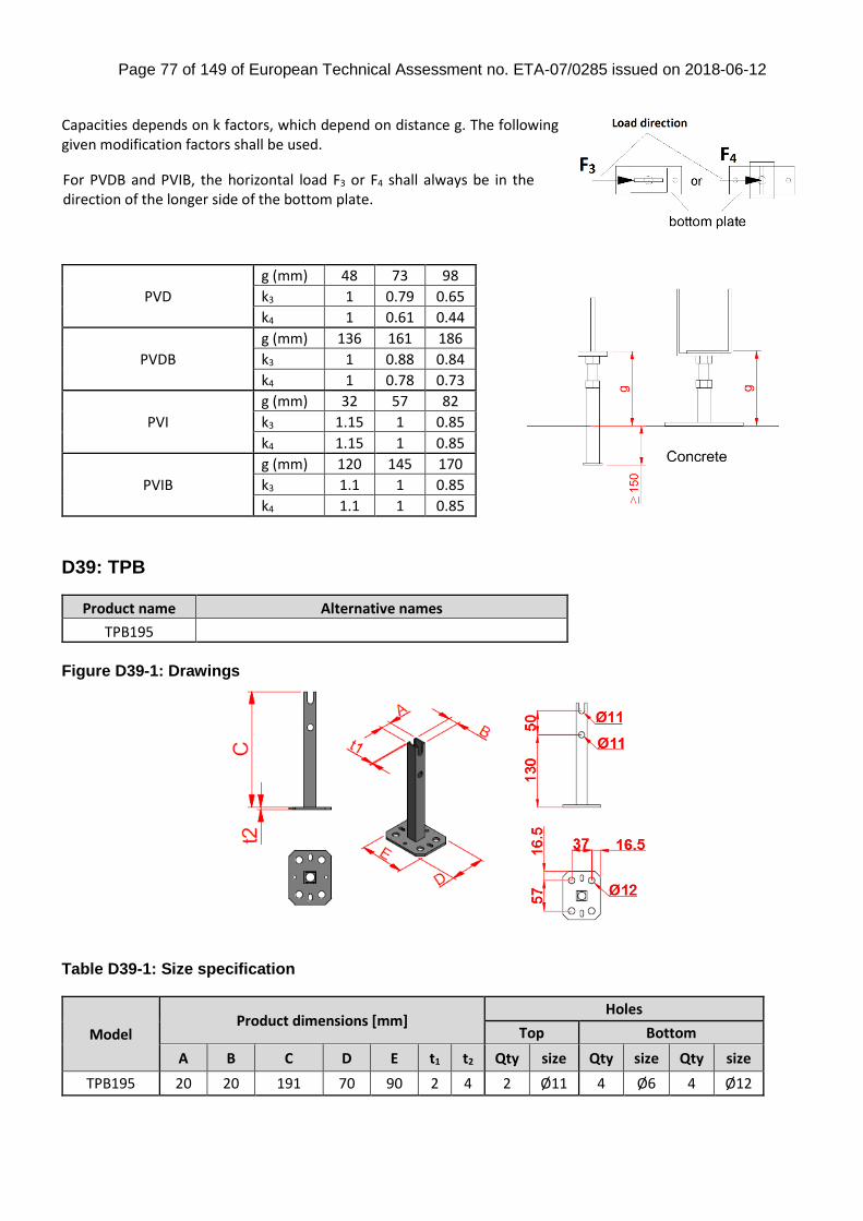
Page 77 of 149 of European Technical Assessment no. ETA-07/0285 issued on 2018-06-12
Capacities depends on k factors, which depend on distance g. The following given modification factors shall be used.
PVD
g (mm) 48 73 98
k3 1 0.79 0.65
k4 1 0.61 0.44
PVDB
g (mm) 136 161 186
k3 1 0.88 0.84
k4 1 0.78 0.73
PVI
g (mm) 32 57 82
k3 1.15 1 0.85
k4 1.15 1 0.85
PVIB
g (mm) 120 145 170
k3 1.1 1 0.85
k4 1.1 1 0.85
D39: TPB
Product name Alternative names
TPB195
Figure D39-1: Drawings
Table D39-1: Size specification
Model Product dimensions [mm]
Holes
Top Bottom
A B C D E t1 t2 Qty size Qty size Qty size
TPB195 20 20 191 70 90 2 4 2 Ø11 4 Ø6 4 Ø12
For PVDB and PVIB, the horizontal load F3 or F4 shall always be in the direction of the longer side of the bottom plate.
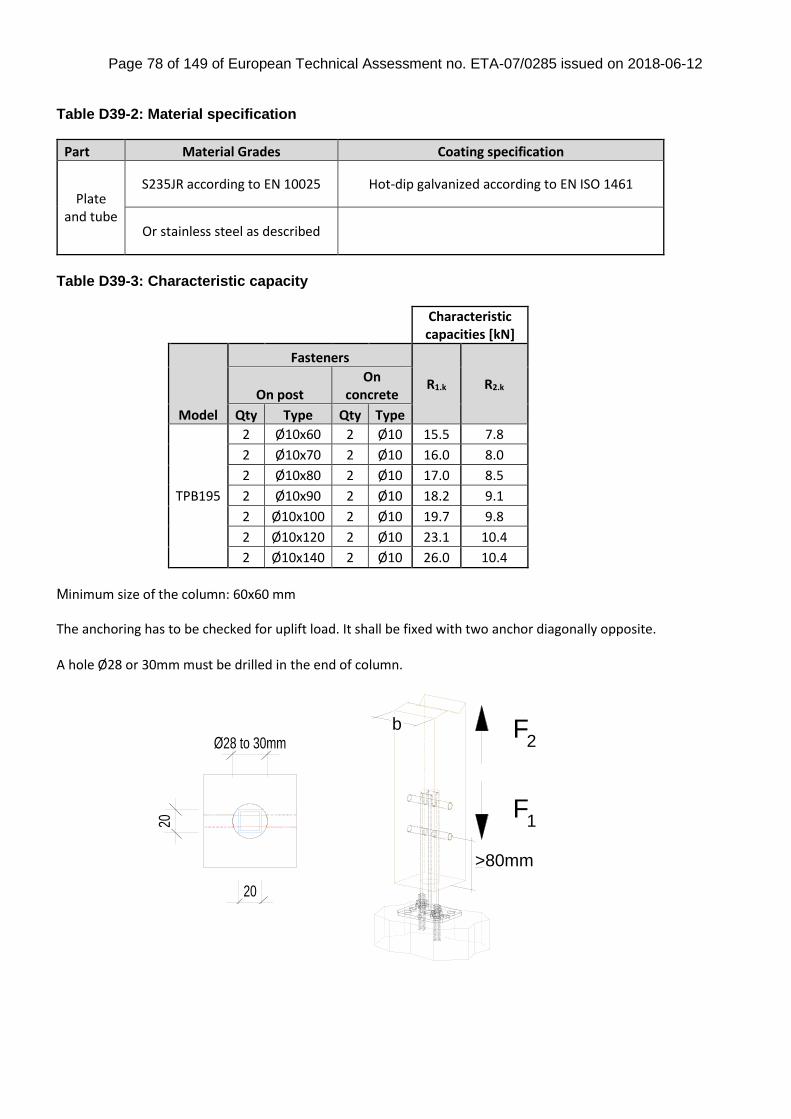
Page 78 of 149 of European Technical Assessment no. ETA-07/0285 issued on 2018-06-12
Table D39-2: Material specification
Part Material Grades Coating specification
Plate and tube
S235JR according to EN 10025 Hot-dip galvanized according to EN ISO 1461
Or stainless steel as described
Table D39-3: Characteristic capacity
Characteristic capacities [kN]
Model
Fasteners
R1.k R2.k On post
On concrete
Qty Type Qty Type
TPB195
2 Ø10x60 2 Ø10 15.5 7.8
2 Ø10x70 2 Ø10 16.0 8.0
2 Ø10x80 2 Ø10 17.0 8.5
2 Ø10x90 2 Ø10 18.2 9.1
2 Ø10x100 2 Ø10 19.7 9.8
2 Ø10x120 2 Ø10 23.1 10.4
2 Ø10x140 2 Ø10 26.0 10.4
Minimum size of the column: 60x60 mm The anchoring has to be checked for uplift load. It shall be fixed with two anchor diagonally opposite. A hole Ø28 or 30mm must be drilled in the end of column.
F
F
>80mm
1
2b
Ø28 to 30mm
20
20
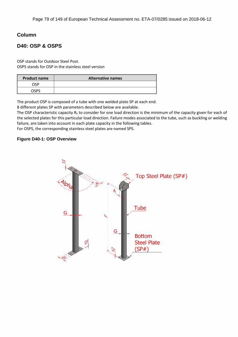
Page 79 of 149 of European Technical Assessment no. ETA-07/0285 issued on 2018-06-12
Column
D40: OSP & OSPS
OSP stands for Outdoor Steel Post. OSPS stands for OSP in the stainless steel version
Product name Alternative names
OSP
OSPS
The product OSP is composed of a tube with one welded plate SP at each end. 8 different plates SP with parameters described below are available. The OSP characteristic capacity Rk to consider for one load direction is the minimum of the capacity given for each of the selected plates for this particular load direction. Failure modes associated to the tube, such as buckling or welding failure, are taken into account in each plate capacity in the following tables. For OSPS, the corresponding stainless steel plates are named SPS. Figure D40-1: OSP Overview
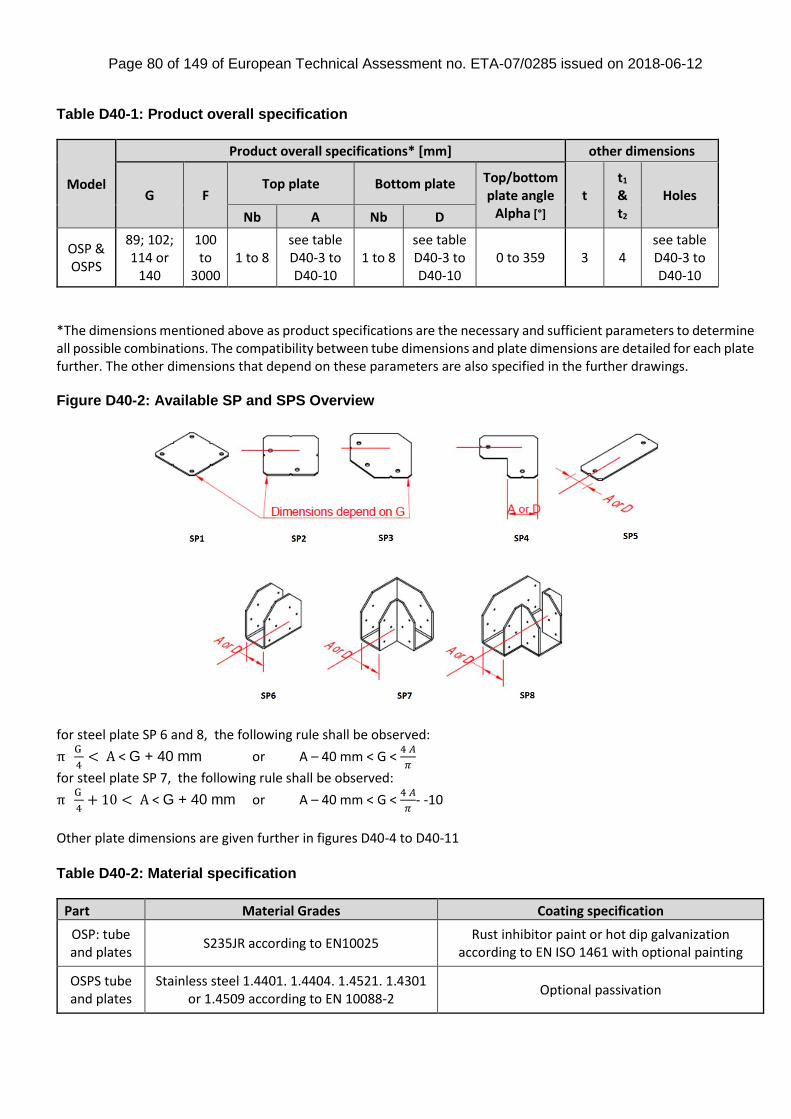
Page 80 of 149 of European Technical Assessment no. ETA-07/0285 issued on 2018-06-12
Table D40-1: Product overall specification
Model
Product overall specifications* [mm] other dimensions
G F Top plate Bottom plate Top/bottom
plate angle Alpha [°]
t t1 & t2
Holes
Nb A Nb D
OSP & OSPS
89; 102; 114 or
140
100 to
3000 1 to 8
see table D40-3 to D40-10
1 to 8 see table D40-3 to D40-10
0 to 359 3 4 see table D40-3 to D40-10
*The dimensions mentioned above as product specifications are the necessary and sufficient parameters to determine all possible combinations. The compatibility between tube dimensions and plate dimensions are detailed for each plate further. The other dimensions that depend on these parameters are also specified in the further drawings. Figure D40-2: Available SP and SPS Overview
for steel plate SP 6 and 8, the following rule shall be observed:
π G
4< A < G + 40 mm or A – 40 mm < G <
4 𝐴
𝜋
for steel plate SP 7, the following rule shall be observed:
π G
4+ 10 < A < G + 40 mm or A – 40 mm < G <
4 𝐴
𝜋- -10
Other plate dimensions are given further in figures D40-4 to D40-11 Table D40-2: Material specification
Part Material Grades Coating specification
OSP: tube and plates
S235JR according to EN10025 Rust inhibitor paint or hot dip galvanization
according to EN ISO 1461 with optional painting
OSPS tube and plates
Stainless steel 1.4401. 1.4404. 1.4521. 1.4301 or 1.4509 according to EN 10088-2
Optional passivation
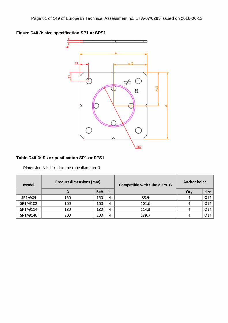
Page 81 of 149 of European Technical Assessment no. ETA-07/0285 issued on 2018-06-12
Figure D40-3: size specification SP1 or SPS1
Table D40-3: Size specification SP1 or SPS1 Dimension A is linked to the tube diameter G:
Model Product dimensions (mm)
Compatible with tube diam. G Anchor holes
A B=A t Qty size
SP1/Ø89 150 150 4 88.9 4 Ø14
SP1/Ø102 160 160 4 101.6 4 Ø14
SP1/Ø114 180 180 4 114.3 4 Ø14
SP1/Ø140 200 200 4 139.7 4 Ø14
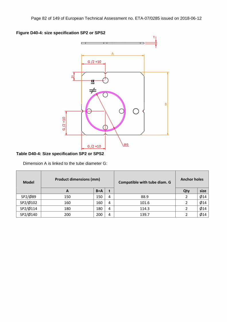
Page 82 of 149 of European Technical Assessment no. ETA-07/0285 issued on 2018-06-12
Figure D40-4: size specification SP2 or SPS2
Table D40-4: Size specification SP2 or SPS2
Dimension A is linked to the tube diameter G:
Model Product dimensions (mm)
Compatible with tube diam. G Anchor holes
A B=A t Qty size
SP2/Ø89 150 150 4 88.9 2 Ø14
SP2/Ø102 160 160 4 101.6 2 Ø14
SP2/Ø114 180 180 4 114.3 2 Ø14
SP2/Ø140 200 200 4 139.7 2 Ø14
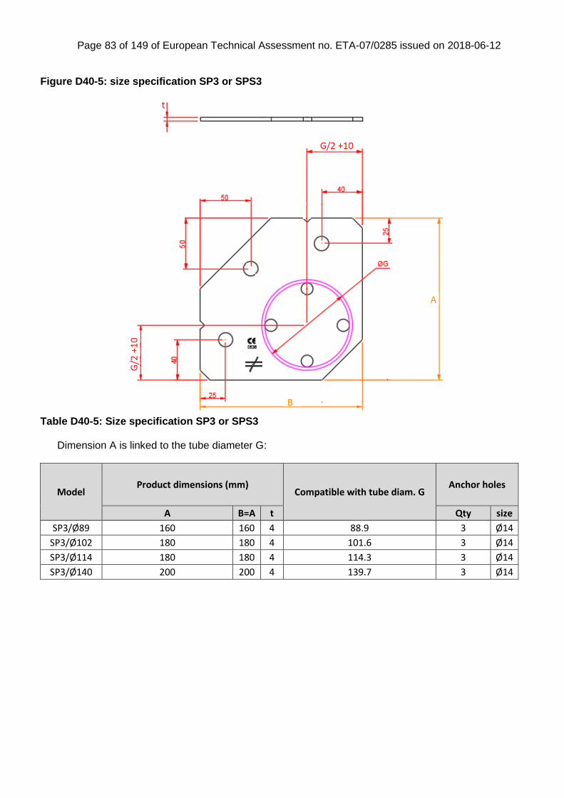
Page 83 of 149 of European Technical Assessment no. ETA-07/0285 issued on 2018-06-12
Figure D40-5: size specification SP3 or SPS3
Table D40-5: Size specification SP3 or SPS3
Dimension A is linked to the tube diameter G:
Model Product dimensions (mm)
Compatible with tube diam. G Anchor holes
A B=A t Qty size
SP3/Ø89 160 160 4 88.9 3 Ø14
SP3/Ø102 180 180 4 101.6 3 Ø14
SP3/Ø114 180 180 4 114.3 3 Ø14
SP3/Ø140 200 200 4 139.7 3 Ø14
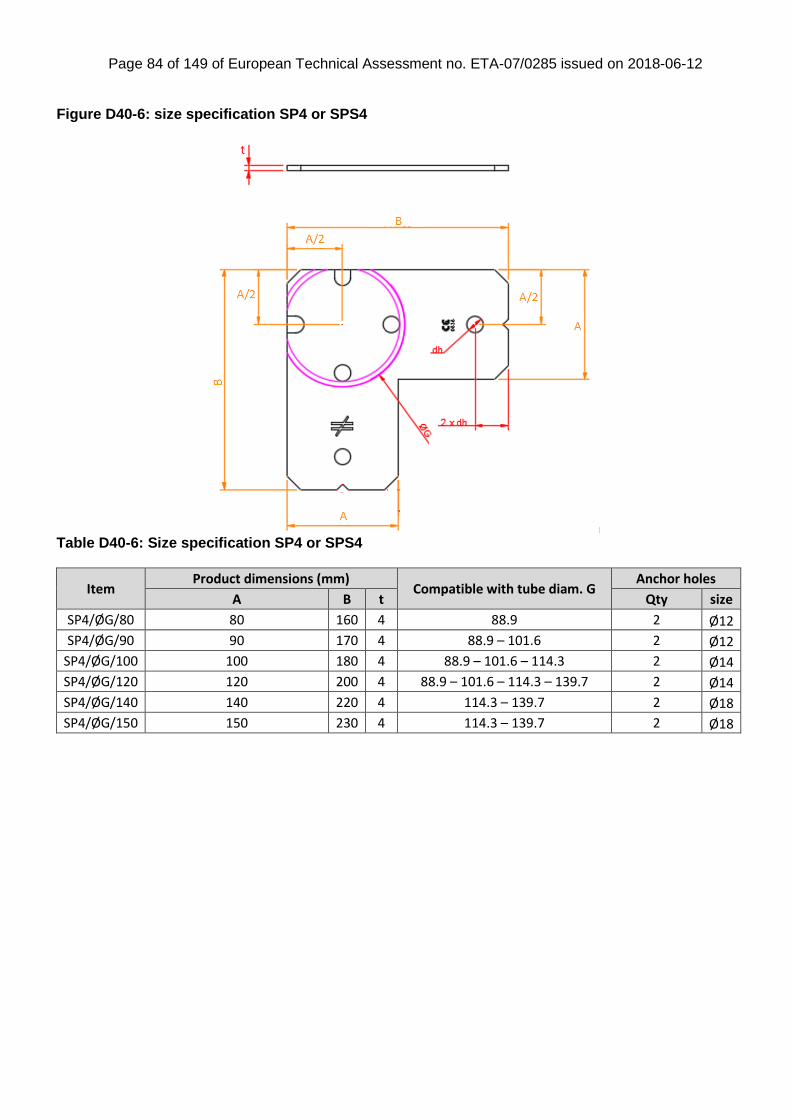
Page 84 of 149 of European Technical Assessment no. ETA-07/0285 issued on 2018-06-12
Figure D40-6: size specification SP4 or SPS4
Table D40-6: Size specification SP4 or SPS4
Item Product dimensions (mm)
Compatible with tube diam. G Anchor holes
A B t Qty size
SP4/ØG/80 80 160 4 88.9 2 Ø12
SP4/ØG/90 90 170 4 88.9 – 101.6 2 Ø12
SP4/ØG/100 100 180 4 88.9 – 101.6 – 114.3 2 Ø14
SP4/ØG/120 120 200 4 88.9 – 101.6 – 114.3 – 139.7 2 Ø14
SP4/ØG/140 140 220 4 114.3 – 139.7 2 Ø18
SP4/ØG/150 150 230 4 114.3 – 139.7 2 Ø18
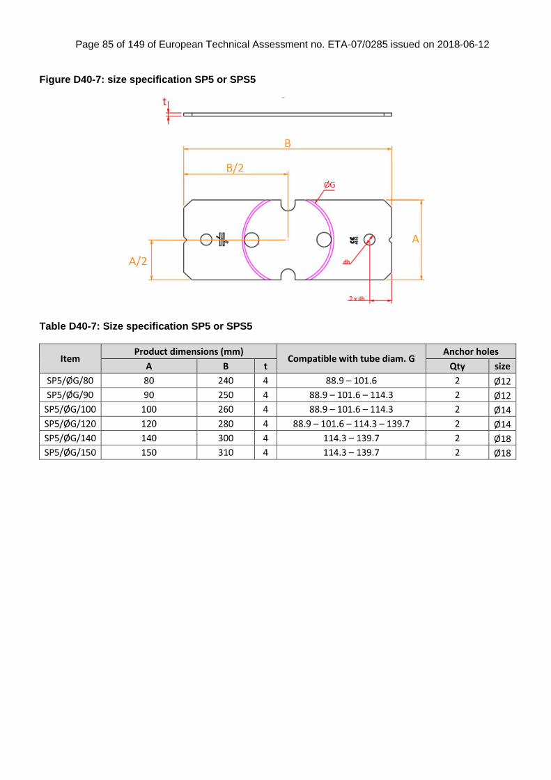
Page 85 of 149 of European Technical Assessment no. ETA-07/0285 issued on 2018-06-12
Figure D40-7: size specification SP5 or SPS5
Table D40-7: Size specification SP5 or SPS5
Item Product dimensions (mm)
Compatible with tube diam. G Anchor holes
A B t Qty size
SP5/ØG/80 80 240 4 88.9 – 101.6 2 Ø12
SP5/ØG/90 90 250 4 88.9 – 101.6 – 114.3 2 Ø12
SP5/ØG/100 100 260 4 88.9 – 101.6 – 114.3 2 Ø14
SP5/ØG/120 120 280 4 88.9 – 101.6 – 114.3 – 139.7 2 Ø14
SP5/ØG/140 140 300 4 114.3 – 139.7 2 Ø18
SP5/ØG/150 150 310 4 114.3 – 139.7 2 Ø18
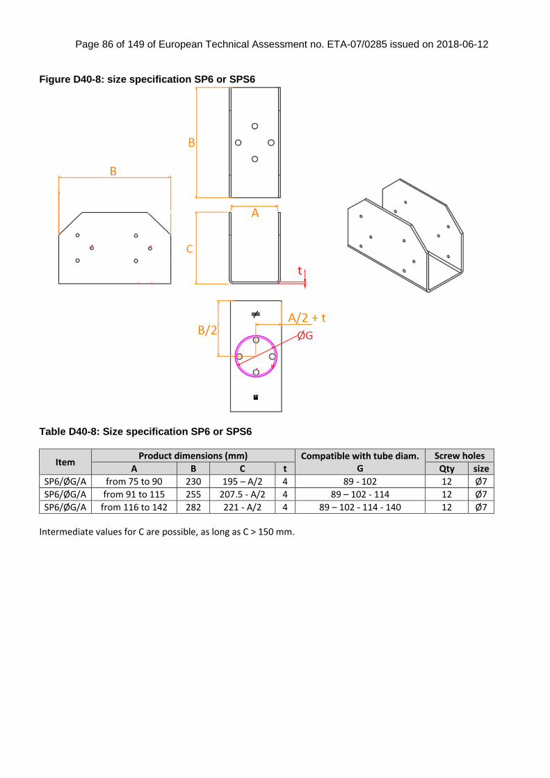
Page 86 of 149 of European Technical Assessment no. ETA-07/0285 issued on 2018-06-12
Figure D40-8: size specification SP6 or SPS6
Table D40-8: Size specification SP6 or SPS6
Item Product dimensions (mm) Compatible with tube diam.
G Screw holes
A B C t Qty size
SP6/ØG/A from 75 to 90 230 195 – A/2 4 89 - 102 12 Ø7
SP6/ØG/A from 91 to 115 255 207.5 - A/2 4 89 – 102 - 114 12 Ø7
SP6/ØG/A from 116 to 142 282 221 - A/2 4 89 – 102 - 114 - 140 12 Ø7 Intermediate values for C are possible, as long as C > 150 mm.

Page 87 of 149 of European Technical Assessment no. ETA-07/0285 issued on 2018-06-12
Figure D40-9: Size specification SP7 or SPS7
Table D40-9: Size specification SP7 or SPS7
Item Product dimensions (mm)
Compatible with tube diam. G Screw holes
A B C t Qty size
SP7/ØG/A from 75 to 142 A + 84 150 4 A – 40 mm < G < 4x A /π -10 12 Ø7
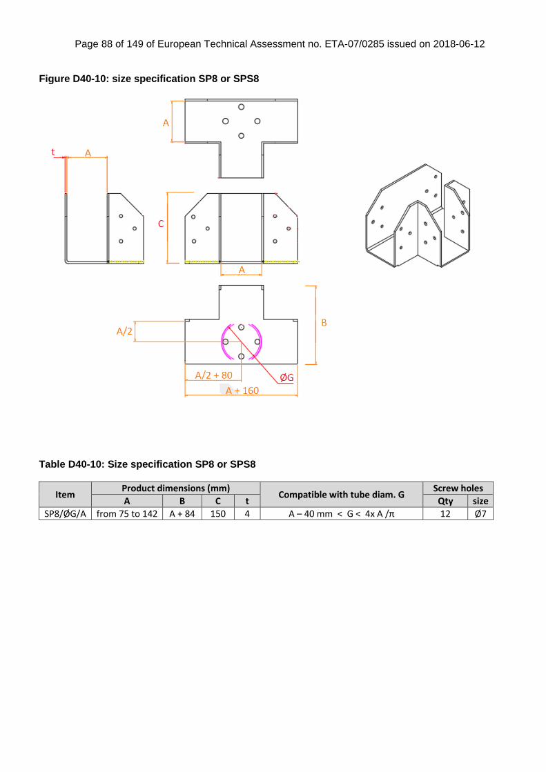
Page 88 of 149 of European Technical Assessment no. ETA-07/0285 issued on 2018-06-12
Figure D40-10: size specification SP8 or SPS8
Table D40-10: Size specification SP8 or SPS8
Item Product dimensions (mm)
Compatible with tube diam. G Screw holes
A B C t Qty size
SP8/ØG/A from 75 to 142 A + 84 150 4 A – 40 mm < G < 4x A /π 12 Ø7
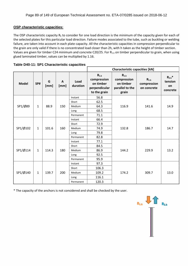
Page 89 of 149 of European Technical Assessment no. ETA-07/0285 issued on 2018-06-12
OSP characteristic capacities: The OSP characteristic capacity Rk to consider for one load direction is the minimum of the capacity given for each of the selected plates for this particular load direction. Failure modes associated to the tube, such as buckling or welding failure, are taken into account in each plate capacity. All the characteristic capacities in compression perpendicular to the grain are only valid if there is no concentrated load closer than 2h, with h taken as the height of timber section. Values are given for timber C24 minimum and concrete C20/25. For R1.k on timber perpendicular to grain, when using glued laminated timber, values can be multiplied by 1.16. Table D40-11: SP1 Characteristic capacities
Characteristic capacities [kN]
Model SP# G
[mm] A
[mm] Load
duration
R1.k compression
on timber perpendicular
to the grain
R1.k compression
on timber parallel to the
grain
R1.k compression on concrete
R2.k* tension
on concrete
SP1/Ø89 1 88.9 150
Instant 56.8
116.9 141.6 14.9
Short 62.5 Medium 64.3 Long 68.5 Permanent 71.1
SP1/Ø102 1 101.6 160
Instant 66.4
132.8 186.7 14.7
Short 72.9 Medium 74.9 Long 79.8 Permanent 82.8
SP1/Ø114 1 114.3 180
Instant 77.1
144.2 229.9 13.2
Short 84.5 Medium 86.9 Long 92.5 Permanent 95.9
SP1/Ø140 1 139.7 200
Instant 97.3
174.2 309.7 13.0
Short 106.3
Medium 109.2 Long 116.1
Permanent 120.3
* The capacity of the anchors is not considered and shall be checked by the user.
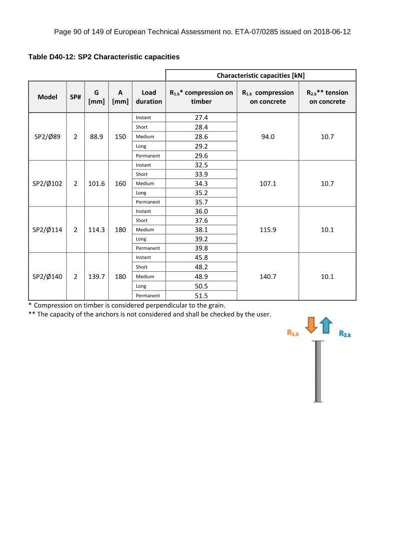
Page 90 of 149 of European Technical Assessment no. ETA-07/0285 issued on 2018-06-12
Table D40-12: SP2 Characteristic capacities
Characteristic capacities [kN]
Model SP# G
[mm] A
[mm] Load
duration R1.k* compression on
timber R1.k compression
on concrete R2.k** tension on concrete
SP2/Ø89 2 88.9 150
Instant 27.4
94.0 10.7
Short 28.4 Medium 28.6 Long 29.2 Permanent 29.6
SP2/Ø102 2 101.6 160
Instant 32.5
107.1 10.7
Short 33.9 Medium 34.3 Long 35.2 Permanent 35.7
SP2/Ø114 2 114.3 180
Instant 36.0
115.9 10.1
Short 37.6 Medium 38.1 Long 39.2 Permanent 39.8
SP2/Ø140 2 139.7 180
Instant 45.8
140.7 10.1
Short 48.2 Medium 48.9 Long 50.5 Permanent 51.5
* Compression on timber is considered perpendicular to the grain. ** The capacity of the anchors is not considered and shall be checked by the user.
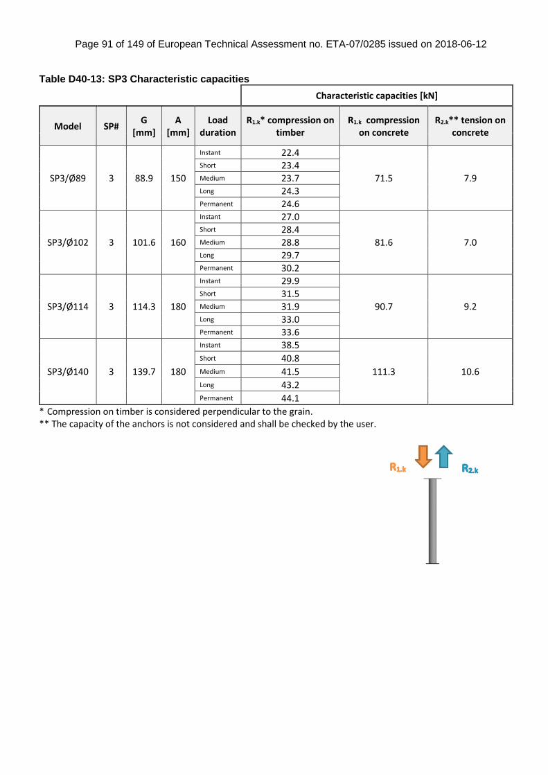
Page 91 of 149 of European Technical Assessment no. ETA-07/0285 issued on 2018-06-12
Table D40-13: SP3 Characteristic capacities
Characteristic capacities [kN]
Model SP# G
[mm] A
[mm] Load
duration R1.k* compression on
timber R1.k compression
on concrete R2.k** tension on
concrete
SP3/Ø89 3 88.9 150
Instant 22.4
71.5 7.9
Short 23.4 Medium 23.7 Long 24.3 Permanent 24.6
SP3/Ø102 3 101.6 160
Instant 27.0
81.6 7.0
Short 28.4 Medium 28.8 Long 29.7 Permanent 30.2
SP3/Ø114 3 114.3 180
Instant 29.9
90.7 9.2
Short 31.5 Medium 31.9 Long 33.0 Permanent 33.6
SP3/Ø140 3 139.7 180
Instant 38.5
111.3 10.6
Short 40.8 Medium 41.5 Long 43.2 Permanent 44.1
* Compression on timber is considered perpendicular to the grain. ** The capacity of the anchors is not considered and shall be checked by the user.

Page 92 of 149 of European Technical Assessment no. ETA-07/0285 issued on 2018-06-12
Figure D40-11: SP4 configurations
If the plate is used to connect two timber part as described in config 1 with equal contact area, then the load applied on each part shall not exceed the half of the total capacity in the table D40-14 below.
If the plate is used to connect two timber part as described in config 2 with one longer timber member (short TM/long TM), then the load applied on each member shall not exceed the values given in the table D40-15 on next page. Table D40-14: SP4 Characteristic capacities (1/2)
* Load bearing capacity for each timber part is described on the next table. ** The capacity of the anchors is not considered and shall be checked by the user.
Total characteristic capacities [kN]
Model SP#
G [mm]
A [mm]
R1.k* to compression on timber perpendicular to the grain
End support R1.k
compression on concrete
R2.k** tension
on concrete Instant
load
Short term load
Med. term load
Long term load
Perm. term load
SP4/Ø89/80 4 88.9 80 52.3 55.1 55.9 57.9 59.0 64.2 4.1
SP4/Ø89/90 4 88.9 90 58.1 62.0 63.3 65.8 67.1 73.9 4.1
SP4/Ø102/90 4 101.6 90 60.6 64.0 65.0 67.5 68.9 73.5 4.7
SP4/Ø89/100 4 88.9 100 64.3 68.6 69.9 73.1 74.9 82.3 4.5
SP4/Ø102/100 4 101.6 100 67.2 71.8 73.3 75.9 77.4 84.1 5.1
SP4/Ø114/100 4 114.3 100 66.7 69.3 70.5 73.2 74.8 79.2 5.9
SP4/Ø89/120 4 88.9 120 78.7 83.6 85.2 88.8 91.0 92.2 4.6
SP4/Ø102/120 4 101.6 120 80.9 86.3 87.9 91.9 94.2 100.9 5.1
SP4/Ø114/120 4 114.3 120 80.2 85.7 87.4 91.5 93.9 100.9 5.7
SP4/Ø140/120 4 139.7 120 82.2 87.2 88.8 92.5 94.6 96.1 7.6
SP4/Ø114/140 4 114.3 140 96.3 102.4 104.4 108.9 111.7 115.3 6.4
SP4/Ø140/140 4 139.7 140 99.7 106.6 108.8 113.3 113.8 121.5 8.4
SP4/Ø114/150 4 114.3 150 104.4 110.9 112.9 117.8 120.7 116.7 6.3
SP4/Ø140/150 4 139.7 150 107.1 114.4 116.7 122.1 125.4 131.8 8.0
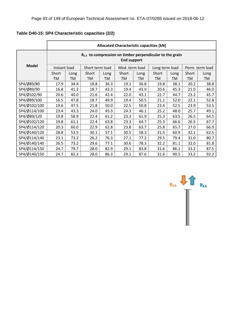
Page 93 of 149 of European Technical Assessment no. ETA-07/0285 issued on 2018-06-12
Table D40-15: SP4 Characteristic capacities (2/2)
Allocated Characteristic capacities [kN]
Model
R1.k to compression on timber perpendicular to the grain End support
Instant load Short term load Med. term load Long term load Perm. term load
Short TM
Long TM
Short TM
Long TM
Short TM
Long TM
Short TM
Long TM
Short TM
Long TM
SP4/Ø89/80 17.9 34.4 18.8 36.3 19.1 36.8 19.8 38.1 20.2 38.8
SP4/Ø89/90 16.8 41.3 18.7 43.3 19.4 43.9 20.6 45.3 21.0 46.0
SP4/Ø102/90 20.6 40.0 21.6 42.4 22.0 43.1 22.7 44.7 23.2 45.7
SP4/Ø89/100 16.5 47.8 18.7 49.9 19.4 50.5 21.1 52.0 22.1 52.8
SP4/Ø102/100 19.6 47.5 21.8 50.0 22.5 50.8 23.4 52.5 23.9 53.5
SP4/Ø114/100 23.4 43.3 24.0 45.3 24.3 46.1 25.2 48.0 25.7 49.1
SP4/Ø89/120 19.8 58.9 22.4 61.2 23.3 61.9 25.3 63.5 26.5 64.5
SP4/Ø102/120 19.8 61.1 22.4 63.8 23.3 64.7 25.3 66.6 26.5 67.7
SP4/Ø114/120 20.3 60.0 22.9 62.8 23.8 63.7 25.8 65.7 27.0 66.9
SP4/Ø140/120 28.8 53.5 30.1 57.1 30.5 58.3 31.5 60.9 32.1 62.5
SP4/Ø114/140 23.1 73.2 26.2 76.3 27.1 77.2 29.5 79.4 31.0 80.7
SP4/Ø140/140 26.5 73.2 29.6 77.1 30.6 78.3 32.2 81.1 32.0 81.8
SP4/Ø114/150 24.7 79.7 28.0 82.9 29.1 83.8 31.6 86.1 33.2 87.5
SP4/Ø140/150 24.7 82.3 28.0 86.3 29.1 87.6 31.6 90.5 33.2 92.2
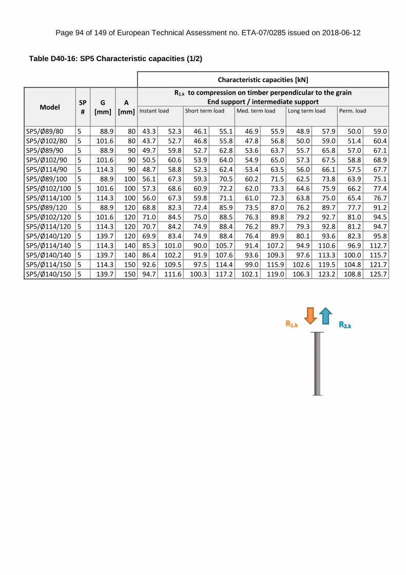
Page 94 of 149 of European Technical Assessment no. ETA-07/0285 issued on 2018-06-12
Table D40-16: SP5 Characteristic capacities (1/2)
Characteristic capacities [kN]
Model SP#
G [mm]
A [mm]
R1.k to compression on timber perpendicular to the grain End support / intermediate support
Instant load Short term load Med. term load Long term load Perm. load
SP5/Ø89/80 5 88.9 80 43.3 52.3 46.1 55.1 46.9 55.9 48.9 57.9 50.0 59.0
SP5/Ø102/80 5 101.6 80 43.7 52.7 46.8 55.8 47.8 56.8 50.0 59.0 51.4 60.4
SP5/Ø89/90 5 88.9 90 49.7 59.8 52.7 62.8 53.6 63.7 55.7 65.8 57.0 67.1
SP5/Ø102/90 5 101.6 90 50.5 60.6 53.9 64.0 54.9 65.0 57.3 67.5 58.8 68.9
SP5/Ø114/90 5 114.3 90 48.7 58.8 52.3 62.4 53.4 63.5 56.0 66.1 57.5 67.7
SP5/Ø89/100 5 88.9 100 56.1 67.3 59.3 70.5 60.2 71.5 62.5 73.8 63.9 75.1
SP5/Ø102/100 5 101.6 100 57.3 68.6 60.9 72.2 62.0 73.3 64.6 75.9 66.2 77.4
SP5/Ø114/100 5 114.3 100 56.0 67.3 59.8 71.1 61.0 72.3 63.8 75.0 65.4 76.7
SP5/Ø89/120 5 88.9 120 68.8 82.3 72.4 85.9 73.5 87.0 76.2 89.7 77.7 91.2
SP5/Ø102/120 5 101.6 120 71.0 84.5 75.0 88.5 76.3 89.8 79.2 92.7 81.0 94.5
SP5/Ø114/120 5 114.3 120 70.7 84.2 74.9 88.4 76.2 89.7 79.3 92.8 81.2 94.7
SP5/Ø140/120 5 139.7 120 69.9 83.4 74.9 88.4 76.4 89.9 80.1 93.6 82.3 95.8
SP5/Ø114/140 5 114.3 140 85.3 101.0 90.0 105.7 91.4 107.2 94.9 110.6 96.9 112.7
SP5/Ø140/140 5 139.7 140 86.4 102.2 91.9 107.6 93.6 109.3 97.6 113.3 100.0 115.7
SP5/Ø114/150 5 114.3 150 92.6 109.5 97.5 114.4 99.0 115.9 102.6 119.5 104.8 121.7
SP5/Ø140/150 5 139.7 150 94.7 111.6 100.3 117.2 102.1 119.0 106.3 123.2 108.8 125.7
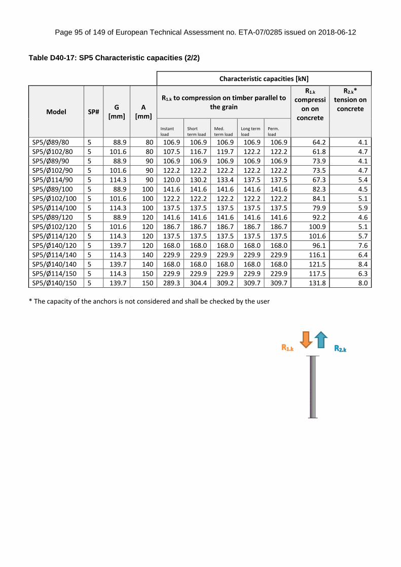
Page 95 of 149 of European Technical Assessment no. ETA-07/0285 issued on 2018-06-12
Table D40-17: SP5 Characteristic capacities (2/2)
* The capacity of the anchors is not considered and shall be checked by the user
Characteristic capacities [kN]
Model SP# G
[mm] A
[mm]
R1.k to compression on timber parallel to the grain
R1.k compressi
on on concrete
R2.k* tension on concrete
Instant load
Short term load
Med. term load
Long term load
Perm. load
SP5/Ø89/80 5 88.9 80 106.9 106.9 106.9 106.9 106.9 64.2 4.1
SP5/Ø102/80 5 101.6 80 107.5 116.7 119.7 122.2 122.2 61.8 4.7
SP5/Ø89/90 5 88.9 90 106.9 106.9 106.9 106.9 106.9 73.9 4.1
SP5/Ø102/90 5 101.6 90 122.2 122.2 122.2 122.2 122.2 73.5 4.7
SP5/Ø114/90 5 114.3 90 120.0 130.2 133.4 137.5 137.5 67.3 5.4
SP5/Ø89/100 5 88.9 100 141.6 141.6 141.6 141.6 141.6 82.3 4.5
SP5/Ø102/100 5 101.6 100 122.2 122.2 122.2 122.2 122.2 84.1 5.1
SP5/Ø114/100 5 114.3 100 137.5 137.5 137.5 137.5 137.5 79.9 5.9
SP5/Ø89/120 5 88.9 120 141.6 141.6 141.6 141.6 141.6 92.2 4.6
SP5/Ø102/120 5 101.6 120 186.7 186.7 186.7 186.7 186.7 100.9 5.1
SP5/Ø114/120 5 114.3 120 137.5 137.5 137.5 137.5 137.5 101.6 5.7
SP5/Ø140/120 5 139.7 120 168.0 168.0 168.0 168.0 168.0 96.1 7.6
SP5/Ø114/140 5 114.3 140 229.9 229.9 229.9 229.9 229.9 116.1 6.4
SP5/Ø140/140 5 139.7 140 168.0 168.0 168.0 168.0 168.0 121.5 8.4
SP5/Ø114/150 5 114.3 150 229.9 229.9 229.9 229.9 229.9 117.5 6.3
SP5/Ø140/150 5 139.7 150 289.3 304.4 309.2 309.7 309.7 131.8 8.0
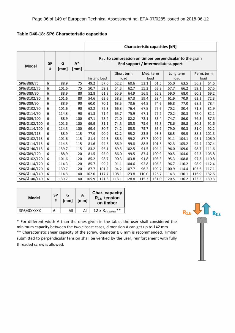
Page 96 of 149 of European Technical Assessment no. ETA-07/0285 issued on 2018-06-12
Table D40-18: SP6 Characteristic capacities
Characteristic capacities [kN]
Model SP #
G [mm]
A* [mm]
R1.k to compression on timber perpendicular to the grain End support / intermediate support
Instant load Short term
load Med. term
load Long term
load Perm. term
load
SP6/Ø89/75 6 88.9 75 49.2 57.6 52.2 60.6 53.1 61.5 55.0 63.5 56.2 64.6
SP6/Ø102/75 6 101.6 75 50.7 59.2 54.3 62.7 55.3 63.8 57.7 66.2 59.1 67.5
SP6/Ø89/80 6 88.9 80 52.8 61.8 55.9 64.9 56.9 65.9 59.0 68.0 60.2 69.2
SP6/Ø102/80 6 101.6 80 54.6 63.6 58.3 67.3 59.4 68.4 61.9 70.9 63.3 72.3
SP6/Ø89/90 6 88.9 90 60.0 70.1 63.5 73.6 64.5 74.6 66.8 77.0 68.2 78.4
SP6/Ø102/90 6 101.6 90 62.2 72.3 66.3 76.4 67.5 77.6 70.2 80.4 71.8 81.9
SP6/Ø114/90 6 114.3 90 61.3 71.4 65.7 75.9 67.1 77.2 70.2 80.3 72.0 82.1
SP6/Ø89/100 6 88.9 100 67.1 78.4 71.0 82.2 72.1 83.4 74.7 86.0 76.3 87.5
SP6/Ø102/100 6 101.6 100 69.9 81.1 74.3 85.5 75.6 86.8 78.6 89.8 80.3 91.6
SP6/Ø114/100 6 114.3 100 69.4 80.7 74.2 85.5 75.7 86.9 79.0 90.3 81.0 92.2
SP6/Ø89/115 6 88.9 115 77.9 90.9 82.2 95.2 83.5 96.5 86.5 99.5 88.3 101.3
SP6/Ø102/115 6 101.6 115 81.4 94.3 86.3 99.2 87.7 100.7 91.1 104.1 93.1 106.0
SP6/Ø114/115 6 114.3 115 81.6 94.6 86.9 99.8 88.5 101.5 92.3 105.2 94.4 107.4
SP6/Ø140/115 6 139.7 115 83.2 96.1 89.5 102.5 91.5 104.4 96.0 109.0 98.7 111.6
SP6/Ø89/120 6 88.9 120 81.5 95.0 86.0 99.5 87.4 100.9 90.5 104.0 92.3 105.8
SP6/Ø102/120 6 101.6 120 85.2 98.7 90.3 103.8 91.8 105.3 95.3 108.8 97.3 110.8
SP6/Ø114/120 6 114.3 120 85.7 99.2 91.1 104.6 92.8 106.3 96.7 110.2 98.9 112.4
SP6/Ø140/120 6 139.7 120 87.7 101.2 94.2 107.7 96.2 109.7 100.9 114.4 103.6 117.1
SP6/Ø114/140 6 114.3 140 102.0 117.7 108.1 123.8 110.0 125.7 114.3 130.1 116.9 132.6
SP6/Ø140/140 6 139.7 140 105.9 121.6 113.1 128.8 115.3 131.0 120.5 136.2 123.5 139.3
* For different width A than the ones given in the table, the user shall considered the minimum capacity between the two closest cases, dimension A can get up to 142 mm. ** Characteristic shear capacity of the screw, diameter ≥ 6 mm is recommended. Timber
submitted to perpendicular tension shall be verified by the user, reinforcement with fully
threaded screw is allowed.
Model SP#
G [mm]
A [mm]
Char. capacity R2.k tension
on timber
SP6/ØXX/XX 6 All All 12 x Rvk.screw**
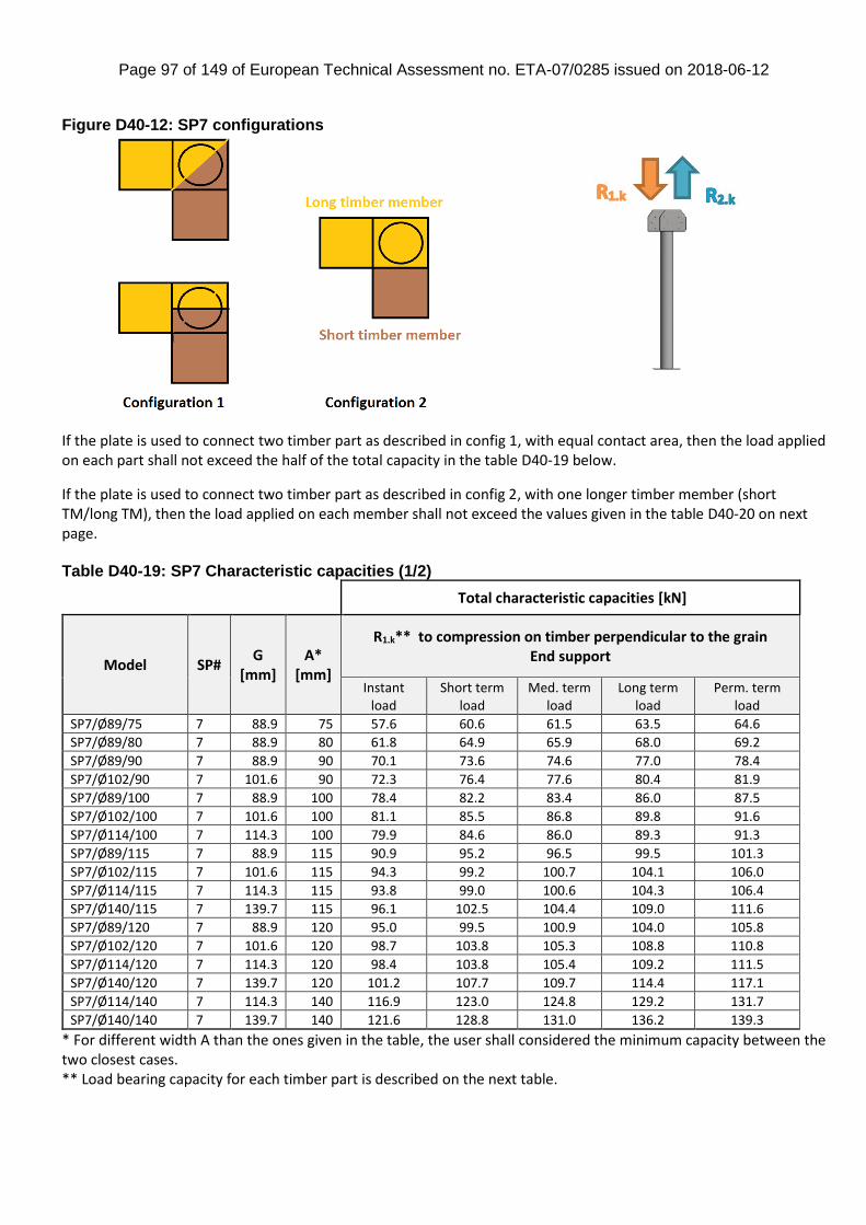
Page 97 of 149 of European Technical Assessment no. ETA-07/0285 issued on 2018-06-12
Figure D40-12: SP7 configurations
If the plate is used to connect two timber part as described in config 1, with equal contact area, then the load applied on each part shall not exceed the half of the total capacity in the table D40-19 below.
If the plate is used to connect two timber part as described in config 2, with one longer timber member (short TM/long TM), then the load applied on each member shall not exceed the values given in the table D40-20 on next page. Table D40-19: SP7 Characteristic capacities (1/2)
Total characteristic capacities [kN]
Model SP# G
[mm] A*
[mm]
R1.k** to compression on timber perpendicular to the grain End support
Instant load
Short term load
Med. term load
Long term load
Perm. term load
SP7/Ø89/75 7 88.9 75 57.6 60.6 61.5 63.5 64.6
SP7/Ø89/80 7 88.9 80 61.8 64.9 65.9 68.0 69.2
SP7/Ø89/90 7 88.9 90 70.1 73.6 74.6 77.0 78.4
SP7/Ø102/90 7 101.6 90 72.3 76.4 77.6 80.4 81.9
SP7/Ø89/100 7 88.9 100 78.4 82.2 83.4 86.0 87.5
SP7/Ø102/100 7 101.6 100 81.1 85.5 86.8 89.8 91.6
SP7/Ø114/100 7 114.3 100 79.9 84.6 86.0 89.3 91.3
SP7/Ø89/115 7 88.9 115 90.9 95.2 96.5 99.5 101.3
SP7/Ø102/115 7 101.6 115 94.3 99.2 100.7 104.1 106.0
SP7/Ø114/115 7 114.3 115 93.8 99.0 100.6 104.3 106.4
SP7/Ø140/115 7 139.7 115 96.1 102.5 104.4 109.0 111.6
SP7/Ø89/120 7 88.9 120 95.0 99.5 100.9 104.0 105.8
SP7/Ø102/120 7 101.6 120 98.7 103.8 105.3 108.8 110.8
SP7/Ø114/120 7 114.3 120 98.4 103.8 105.4 109.2 111.5
SP7/Ø140/120 7 139.7 120 101.2 107.7 109.7 114.4 117.1
SP7/Ø114/140 7 114.3 140 116.9 123.0 124.8 129.2 131.7
SP7/Ø140/140 7 139.7 140 121.6 128.8 131.0 136.2 139.3
* For different width A than the ones given in the table, the user shall considered the minimum capacity between the two closest cases. ** Load bearing capacity for each timber part is described on the next table.
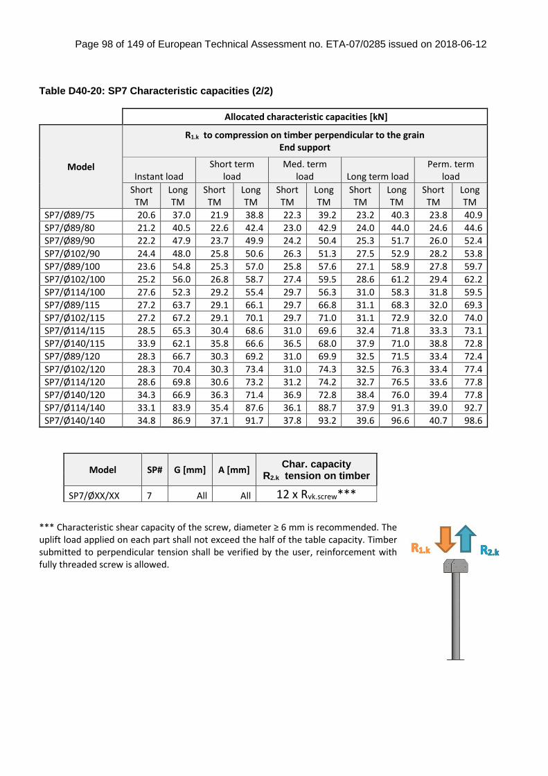
Page 98 of 149 of European Technical Assessment no. ETA-07/0285 issued on 2018-06-12
Table D40-20: SP7 Characteristic capacities (2/2)
Allocated characteristic capacities [kN]
Model
R1.k to compression on timber perpendicular to the grain End support
Instant load Short term
load Med. term
load Long term load Perm. term
load
Short TM
Long TM
Short TM
Long TM
Short TM
Long TM
Short TM
Long TM
Short TM
Long TM
SP7/Ø89/75 20.6 37.0 21.9 38.8 22.3 39.2 23.2 40.3 23.8 40.9
SP7/Ø89/80 21.2 40.5 22.6 42.4 23.0 42.9 24.0 44.0 24.6 44.6
SP7/Ø89/90 22.2 47.9 23.7 49.9 24.2 50.4 25.3 51.7 26.0 52.4
SP7/Ø102/90 24.4 48.0 25.8 50.6 26.3 51.3 27.5 52.9 28.2 53.8
SP7/Ø89/100 23.6 54.8 25.3 57.0 25.8 57.6 27.1 58.9 27.8 59.7
SP7/Ø102/100 25.2 56.0 26.8 58.7 27.4 59.5 28.6 61.2 29.4 62.2
SP7/Ø114/100 27.6 52.3 29.2 55.4 29.7 56.3 31.0 58.3 31.8 59.5
SP7/Ø89/115 27.2 63.7 29.1 66.1 29.7 66.8 31.1 68.3 32.0 69.3
SP7/Ø102/115 27.2 67.2 29.1 70.1 29.7 71.0 31.1 72.9 32.0 74.0
SP7/Ø114/115 28.5 65.3 30.4 68.6 31.0 69.6 32.4 71.8 33.3 73.1
SP7/Ø140/115 33.9 62.1 35.8 66.6 36.5 68.0 37.9 71.0 38.8 72.8
SP7/Ø89/120 28.3 66.7 30.3 69.2 31.0 69.9 32.5 71.5 33.4 72.4
SP7/Ø102/120 28.3 70.4 30.3 73.4 31.0 74.3 32.5 76.3 33.4 77.4
SP7/Ø114/120 28.6 69.8 30.6 73.2 31.2 74.2 32.7 76.5 33.6 77.8
SP7/Ø140/120 34.3 66.9 36.3 71.4 36.9 72.8 38.4 76.0 39.4 77.8
SP7/Ø114/140 33.1 83.9 35.4 87.6 36.1 88.7 37.9 91.3 39.0 92.7
SP7/Ø140/140 34.8 86.9 37.1 91.7 37.8 93.2 39.6 96.6 40.7 98.6
*** Characteristic shear capacity of the screw, diameter ≥ 6 mm is recommended. The uplift load applied on each part shall not exceed the half of the table capacity. Timber submitted to perpendicular tension shall be verified by the user, reinforcement with fully threaded screw is allowed.
Model SP# G [mm] A [mm] Char. capacity
R2.k tension on timber
SP7/ØXX/XX 7 All All 12 x Rvk.screw***
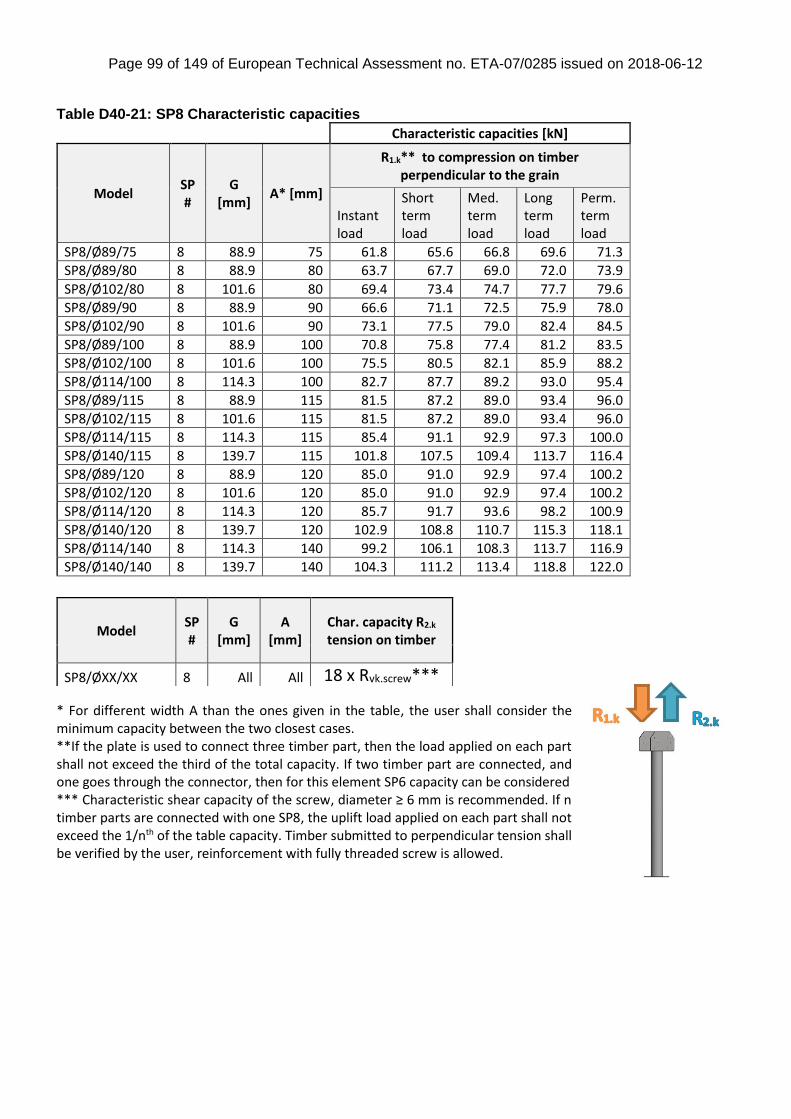
Page 99 of 149 of European Technical Assessment no. ETA-07/0285 issued on 2018-06-12
Table D40-21: SP8 Characteristic capacities
Characteristic capacities [kN]
Model SP#
G [mm]
A* [mm]
R1.k** to compression on timber perpendicular to the grain
Instant load
Short term load
Med. term load
Long term load
Perm. term load
SP8/Ø89/75 8 88.9 75 61.8 65.6 66.8 69.6 71.3
SP8/Ø89/80 8 88.9 80 63.7 67.7 69.0 72.0 73.9
SP8/Ø102/80 8 101.6 80 69.4 73.4 74.7 77.7 79.6
SP8/Ø89/90 8 88.9 90 66.6 71.1 72.5 75.9 78.0
SP8/Ø102/90 8 101.6 90 73.1 77.5 79.0 82.4 84.5
SP8/Ø89/100 8 88.9 100 70.8 75.8 77.4 81.2 83.5
SP8/Ø102/100 8 101.6 100 75.5 80.5 82.1 85.9 88.2
SP8/Ø114/100 8 114.3 100 82.7 87.7 89.2 93.0 95.4
SP8/Ø89/115 8 88.9 115 81.5 87.2 89.0 93.4 96.0
SP8/Ø102/115 8 101.6 115 81.5 87.2 89.0 93.4 96.0
SP8/Ø114/115 8 114.3 115 85.4 91.1 92.9 97.3 100.0
SP8/Ø140/115 8 139.7 115 101.8 107.5 109.4 113.7 116.4
SP8/Ø89/120 8 88.9 120 85.0 91.0 92.9 97.4 100.2
SP8/Ø102/120 8 101.6 120 85.0 91.0 92.9 97.4 100.2
SP8/Ø114/120 8 114.3 120 85.7 91.7 93.6 98.2 100.9
SP8/Ø140/120 8 139.7 120 102.9 108.8 110.7 115.3 118.1
SP8/Ø114/140 8 114.3 140 99.2 106.1 108.3 113.7 116.9
SP8/Ø140/140 8 139.7 140 104.3 111.2 113.4 118.8 122.0
* For different width A than the ones given in the table, the user shall consider the minimum capacity between the two closest cases. **If the plate is used to connect three timber part, then the load applied on each part shall not exceed the third of the total capacity. If two timber part are connected, and one goes through the connector, then for this element SP6 capacity can be considered *** Characteristic shear capacity of the screw, diameter ≥ 6 mm is recommended. If n timber parts are connected with one SP8, the uplift load applied on each part shall not exceed the 1/nth of the table capacity. Timber submitted to perpendicular tension shall be verified by the user, reinforcement with fully threaded screw is allowed.
Model SP#
G [mm]
A [mm]
Char. capacity R2.k tension on timber
SP8/ØXX/XX 8 All All 18 x Rvk.screw***
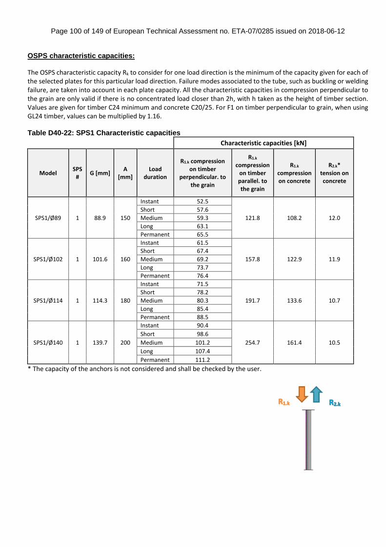
Page 100 of 149 of European Technical Assessment no. ETA-07/0285 issued on 2018-06-12
OSPS characteristic capacities: The OSPS characteristic capacity Rk to consider for one load direction is the minimum of the capacity given for each of the selected plates for this particular load direction. Failure modes associated to the tube, such as buckling or welding failure, are taken into account in each plate capacity. All the characteristic capacities in compression perpendicular to the grain are only valid if there is no concentrated load closer than 2h, with h taken as the height of timber section. Values are given for timber C24 minimum and concrete C20/25. For F1 on timber perpendicular to grain, when using GL24 timber, values can be multiplied by 1.16. Table D40-22: SPS1 Characteristic capacities
Characteristic capacities [kN]
Model SPS
# G [mm]
A [mm]
Load duration
R1.k compression on timber
perpendicular. to the grain
R1.k compression
on timber parallel. to the grain
R1.k compression on concrete
R2.k* tension on concrete
SPS1/Ø89 1 88.9 150
Instant 52.5
121.8 108.2 12.0
Short 57.6
Medium 59.3
Long 63.1
Permanent 65.5
SPS1/Ø102 1 101.6 160
Instant 61.5
157.8 122.9 11.9
Short 67.4
Medium 69.2
Long 73.7
Permanent 76.4
SPS1/Ø114 1 114.3 180
Instant 71.5
191.7 133.6 10.7
Short 78.2
Medium 80.3
Long 85.4
Permanent 88.5
SPS1/Ø140 1 139.7 200
Instant 90.4
254.7 161.4 10.5
Short 98.6
Medium 101.2
Long 107.4
Permanent 111.2
* The capacity of the anchors is not considered and shall be checked by the user.
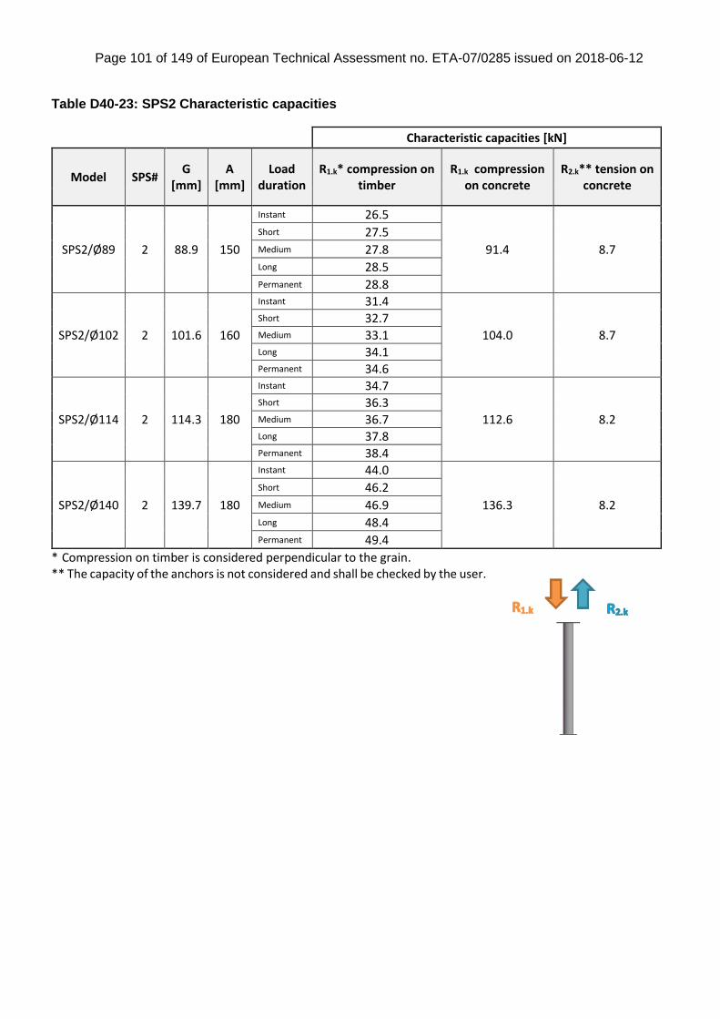
Page 101 of 149 of European Technical Assessment no. ETA-07/0285 issued on 2018-06-12
Table D40-23: SPS2 Characteristic capacities
Characteristic capacities [kN]
Model SPS# G
[mm] A
[mm] Load
duration R1.k* compression on
timber R1.k compression
on concrete R2.k** tension on
concrete
SPS2/Ø89 2 88.9 150
Instant 26.5
91.4 8.7
Short 27.5 Medium 27.8 Long 28.5 Permanent 28.8
SPS2/Ø102 2 101.6 160
Instant 31.4
104.0 8.7
Short 32.7 Medium 33.1 Long 34.1 Permanent 34.6
SPS2/Ø114 2 114.3 180
Instant 34.7
112.6 8.2
Short 36.3 Medium 36.7 Long 37.8 Permanent 38.4
SPS2/Ø140 2 139.7 180
Instant 44.0
136.3 8.2
Short 46.2 Medium 46.9 Long 48.4 Permanent 49.4
* Compression on timber is considered perpendicular to the grain. ** The capacity of the anchors is not considered and shall be checked by the user.
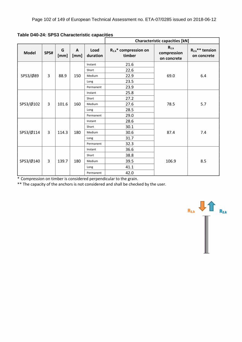
Page 102 of 149 of European Technical Assessment no. ETA-07/0285 issued on 2018-06-12
Table D40-24: SPS3 Characteristic capacities
Characteristic capacities [kN]
Model SPS# G
[mm] A
[mm] Load
duration R1.k* compression on
timber
R1.k compression on concrete
R2.k** tension on concrete
SPS3/Ø89 3 88.9 150
Instant 21.6
69.0 6.4
Short 22.6 Medium 22.9 Long 23.5 Permanent 23.9
SPS3/Ø102 3 101.6 160
Instant 25.8
78.5 5.7
Short 27.2 Medium 27.6 Long 28.5 Permanent 29.0
SPS3/Ø114 3 114.3 180
Instant 28.6
87.4 7.4
Short 30.1 Medium 30.6 Long 31.7 Permanent 32.3
SPS3/Ø140 3 139.7 180
Instant 36.6
106.9 8.5
Short 38.8 Medium 39.5 Long 41.1 Permanent 42.0
* Compression on timber is considered perpendicular to the grain. ** The capacity of the anchors is not considered and shall be checked by the user.
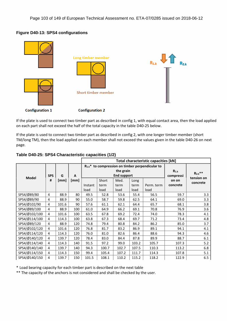
Page 103 of 149 of European Technical Assessment no. ETA-07/0285 issued on 2018-06-12
Figure D40-13: SPS4 configurations
If the plate is used to connect two timber part as described in config 1, with equal contact area, then the load applied on each part shall not exceed the half of the total capacity in the table D40-25 below.
If the plate is used to connect two timber part as described in config 2, with one longer timber member (short TM/long TM), then the load applied on each member shall not exceed the values given in the table D40-26 on next page. Table D40-25: SPS4 Characteristic capacities (1/2)
* Load bearing capacity for each timber part is described on the next table ** The capacity of the anchors is not considered and shall be checked by the user.
Total characteristic capacities [kN]
Model SPS
# G
[mm] A
[mm]
R1.k* to compression on timber perpendicular to the grain
End support R1.k
compression on
concrete
R2.k** tension on concrete
Instant load
Short term load
Med. term load
Long term load
Perm. term load
SPS4/Ø89/80 4 88.9 80 49.5 52.8 53.6 55.4 56.5 59.7 3.3
SPS4/Ø89/90 4 88.9 90 55.0 58.7 59.8 62.5 64.1 69.0 3.3
SPS4/Ø102/90 4 101.6 90 57.6 61.1 62.1 64.4 65.7 68.1 3.8
SPS4/Ø89/100 4 88.9 100 61.0 64.9 66.2 69.1 70.8 76.9 3.6
SPS4/Ø102/100 4 101.6 100 63.5 67.8 69.2 72.4 74.0 78.3 4.1
SPS4/Ø114/100 4 114.3 100 63.8 67.3 68.4 69.7 71.2 73.4 4.8
SPS4/Ø89/120 4 88.9 120 74.8 79.4 80.8 84.2 86.2 85.0 3.7
SPS4/Ø102/120 4 101.6 120 76.8 81.7 83.2 86.9 89.1 94.1 4.1
SPS4/Ø114/120 4 114.3 120 76.0 81.0 82.6 86.4 88.6 94.3 4.6
SPS4/Ø140/120 4 139.7 120 78.4 83.0 84.4 87.8 89.9 88.7 6.1
SPS4/Ø114/140 4 114.3 140 91.5 97.2 99.0 103.2 105.7 107.3 5.2
SPS4/Ø140/140 4 139.7 140 94.3 100.7 102.7 107.5 110.3 113.2 6.8
SPS4/Ø114/150 4 114.3 150 99.4 105.4 107.2 111.7 114.3 107.8 5.1
SPS4/Ø140/150 4 139.7 150 101.5 108.1 110.2 115.2 118.2 122.9 6.5
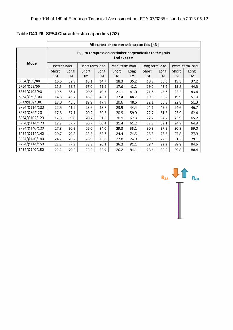
Page 104 of 149 of European Technical Assessment no. ETA-07/0285 issued on 2018-06-12
Table D40-26: SPS4 Characteristic capacities (2/2)
Allocated characteristic capacities [kN]
Model
R1.k to compression on timber perpendicular to the grain End support
Instant load Short term load Med. term load Long term load Perm. term load
Short TM
Long TM
Short TM
Long TM
Short TM
Long TM
Short TM
Long TM
Short TM
Long TM
SPS4/Ø89/80 16.6 32.9 18.1 34.7 18.3 35.2 18.9 36.5 19.3 37.2
SPS4/Ø89/90 15.3 39.7 17.0 41.6 17.6 42.2 19.0 43.5 19.8 44.3
SPS4/Ø102/90 19.5 38.1 20.8 40.3 21.1 41.0 21.8 42.6 22.2 43.6
SPS4/Ø89/100 14.8 46.2 16.8 48.1 17.4 48.7 19.0 50.2 19.9 51.0
SP4/Ø102/100 18.0 45.5 19.9 47.9 20.6 48.6 22.1 50.3 22.8 51.3
SPS4/Ø114/100 22.6 41.2 23.6 43.7 23.9 44.4 24.1 45.6 24.6 46.7
SPS4/Ø89/120 17.8 57.1 20.2 59.2 20.9 59.9 22.7 61.5 23.9 62.4
SPS4/Ø102/120 17.8 59.0 20.2 61.5 20.9 62.3 22.7 64.2 23.9 65.2
SPS4/Ø114/120 18.3 57.7 20.7 60.4 21.4 61.2 23.2 63.1 24.3 64.3
SPS4/Ø140/120 27.8 50.6 29.0 54.0 29.3 55.1 30.3 57.6 30.8 59.0
SPS4/Ø114/140 20.7 70.8 23.5 73.7 24.4 74.5 26.5 76.6 27.8 77.9
SPS4/Ø140/140 24.2 70.2 26.9 73.8 27.8 74.9 29.9 77.5 31.2 79.1
SPS4/Ø114/150 22.2 77.2 25.2 80.2 26.2 81.1 28.4 83.2 29.8 84.5
SPS4/Ø140/150 22.2 79.2 25.2 82.9 26.2 84.1 28.4 86.8 29.8 88.4
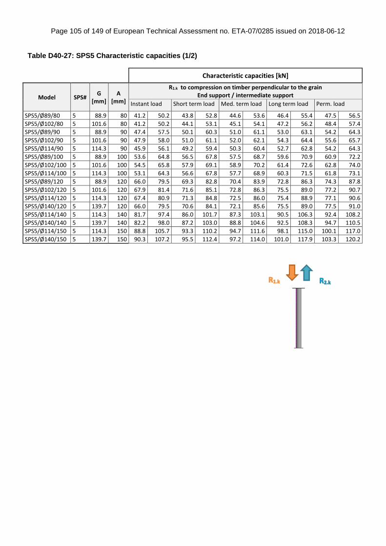
Page 105 of 149 of European Technical Assessment no. ETA-07/0285 issued on 2018-06-12
Table D40-27: SPS5 Characteristic capacities (1/2)
Characteristic capacities [kN]
Model SPS# G
[mm] A
[mm]
R1.k to compression on timber perpendicular to the grain End support / intermediate support
Instant load Short term load Med. term load Long term load Perm. load
SPS5/Ø89/80 5 88.9 80 41.2 50.2 43.8 52.8 44.6 53.6 46.4 55.4 47.5 56.5
SPS5/Ø102/80 5 101.6 80 41.2 50.2 44.1 53.1 45.1 54.1 47.2 56.2 48.4 57.4
SPS5/Ø89/90 5 88.9 90 47.4 57.5 50.1 60.3 51.0 61.1 53.0 63.1 54.2 64.3
SPS5/Ø102/90 5 101.6 90 47.9 58.0 51.0 61.1 52.0 62.1 54.3 64.4 55.6 65.7
SPS5/Ø114/90 5 114.3 90 45.9 56.1 49.2 59.4 50.3 60.4 52.7 62.8 54.2 64.3
SPS5/Ø89/100 5 88.9 100 53.6 64.8 56.5 67.8 57.5 68.7 59.6 70.9 60.9 72.2
SPS5/Ø102/100 5 101.6 100 54.5 65.8 57.9 69.1 58.9 70.2 61.4 72.6 62.8 74.0
SPS5/Ø114/100 5 114.3 100 53.1 64.3 56.6 67.8 57.7 68.9 60.3 71.5 61.8 73.1
SPS5/Ø89/120 5 88.9 120 66.0 79.5 69.3 82.8 70.4 83.9 72.8 86.3 74.3 87.8
SPS5/Ø102/120 5 101.6 120 67.9 81.4 71.6 85.1 72.8 86.3 75.5 89.0 77.2 90.7
SPS5/Ø114/120 5 114.3 120 67.4 80.9 71.3 84.8 72.5 86.0 75.4 88.9 77.1 90.6
SPS5/Ø140/120 5 139.7 120 66.0 79.5 70.6 84.1 72.1 85.6 75.5 89.0 77.5 91.0
SPS5/Ø114/140 5 114.3 140 81.7 97.4 86.0 101.7 87.3 103.1 90.5 106.3 92.4 108.2
SPS5/Ø140/140 5 139.7 140 82.2 98.0 87.2 103.0 88.8 104.6 92.5 108.3 94.7 110.5
SPS5/Ø114/150 5 114.3 150 88.8 105.7 93.3 110.2 94.7 111.6 98.1 115.0 100.1 117.0
SPS5/Ø140/150 5 139.7 150 90.3 107.2 95.5 112.4 97.2 114.0 101.0 117.9 103.3 120.2
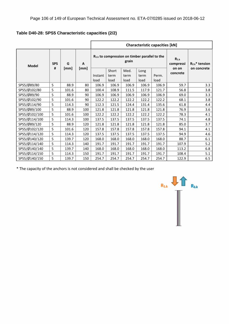
Page 106 of 149 of European Technical Assessment no. ETA-07/0285 issued on 2018-06-12
Table D40-28: SPS5 Characteristic capacities (2/2)
* The capacity of the anchors is not considered and shall be checked by the user
Characteristic capacities [kN]
Model SPS
# G
[mm] A
[mm]
R1.k to compression on timber parallel to the grain
R1.k compressi
on on concrete
R2.k* tension on concrete
Instant load
Short term load
Med. term load
Long term load
Perm. load
SPS5/Ø89/80 5 88.9 80 106.9 106.9 106.9 106.9 106.9 59.7 3.3
SPS5/Ø102/80 5 101.6 80 100.4 108.9 111.5 117.9 121.7 56.8 3.8
SPS5/Ø89/90 5 88.9 90 106.9 106.9 106.9 106.9 106.9 69.0 3.3
SPS5/Ø102/90 5 101.6 90 122.2 122.2 122.2 122.2 122.2 68.1 3.8
SPS5/Ø114/90 5 114.3 90 112.3 121.5 124.4 131.4 135.6 61.8 4.4
SPS5/Ø89/100 5 88.9 100 121.8 121.8 121.8 121.8 121.8 76.9 3.6
SPS5/Ø102/100 5 101.6 100 122.2 122.2 122.2 122.2 122.2 78.3 4.1
SPS5/Ø114/100 5 114.3 100 137.5 137.5 137.5 137.5 137.5 74.1 4.8
SPS5/Ø89/120 5 88.9 120 121.8 121.8 121.8 121.8 121.8 85.0 3.7
SPS5/Ø102/120 5 101.6 120 157.8 157.8 157.8 157.8 157.8 94.1 4.1
SPS5/Ø114/120 5 114.3 120 137.5 137.5 137.5 137.5 137.5 94.9 4.6
SPS5/Ø140/120 5 139.7 120 168.0 168.0 168.0 168.0 168.0 88.7 6.1
SPS5/Ø114/140 5 114.3 140 191.7 191.7 191.7 191.7 191.7 107.9 5.2
SPS5/Ø140/140 5 139.7 140 168.0 168.0 168.0 168.0 168.0 113.2 6.8
SPS5/Ø114/150 5 114.3 150 191.7 191.7 191.7 191.7 191.7 108.4 5.1
SPS5/Ø140/150 5 139.7 150 254.7 254.7 254.7 254.7 254.7 122.9 6.5
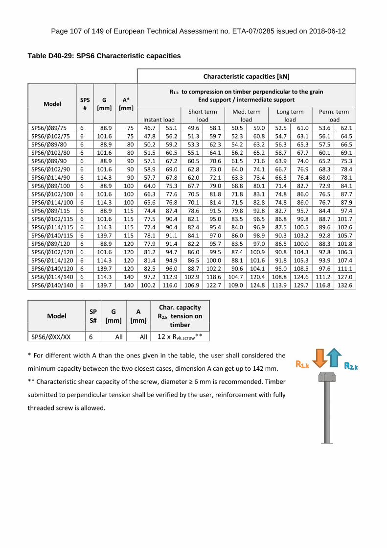
Page 107 of 149 of European Technical Assessment no. ETA-07/0285 issued on 2018-06-12
Table D40-29: SPS6 Characteristic capacities
Characteristic capacities [kN]
Model SPS
# G
[mm] A*
[mm]
R1.k to compression on timber perpendicular to the grain End support / intermediate support
Instant load Short term
load Med. term
load Long term
load Perm. term
load
SPS6/Ø89/75 6 88.9 75 46.7 55.1 49.6 58.1 50.5 59.0 52.5 61.0 53.6 62.1
SPS6/Ø102/75 6 101.6 75 47.8 56.2 51.3 59.7 52.3 60.8 54.7 63.1 56.1 64.5
SPS6/Ø89/80 6 88.9 80 50.2 59.2 53.3 62.3 54.2 63.2 56.3 65.3 57.5 66.5
SPS6/Ø102/80 6 101.6 80 51.5 60.5 55.1 64.1 56.2 65.2 58.7 67.7 60.1 69.1
SPS6/Ø89/90 6 88.9 90 57.1 67.2 60.5 70.6 61.5 71.6 63.9 74.0 65.2 75.3
SPS6/Ø102/90 6 101.6 90 58.9 69.0 62.8 73.0 64.0 74.1 66.7 76.9 68.3 78.4
SPS6/Ø114/90 6 114.3 90 57.7 67.8 62.0 72.1 63.3 73.4 66.3 76.4 68.0 78.1
SPS6/Ø89/100 6 88.9 100 64.0 75.3 67.7 79.0 68.8 80.1 71.4 82.7 72.9 84.1
SPS6/Ø102/100 6 101.6 100 66.3 77.6 70.5 81.8 71.8 83.1 74.8 86.0 76.5 87.7
SPS6/Ø114/100 6 114.3 100 65.6 76.8 70.1 81.4 71.5 82.8 74.8 86.0 76.7 87.9
SPS6/Ø89/115 6 88.9 115 74.4 87.4 78.6 91.5 79.8 92.8 82.7 95.7 84.4 97.4
SPS6/Ø102/115 6 101.6 115 77.5 90.4 82.1 95.0 83.5 96.5 86.8 99.8 88.7 101.7
SPS6/Ø114/115 6 114.3 115 77.4 90.4 82.4 95.4 84.0 96.9 87.5 100.5 89.6 102.6
SPS6/Ø140/115 6 139.7 115 78.1 91.1 84.1 97.0 86.0 98.9 90.3 103.2 92.8 105.7
SPS6/Ø89/120 6 88.9 120 77.9 91.4 82.2 95.7 83.5 97.0 86.5 100.0 88.3 101.8
SPS6/Ø102/120 6 101.6 120 81.2 94.7 86.0 99.5 87.4 100.9 90.8 104.3 92.8 106.3
SPS6/Ø114/120 6 114.3 120 81.4 94.9 86.5 100.0 88.1 101.6 91.8 105.3 93.9 107.4
SPS6/Ø140/120 6 139.7 120 82.5 96.0 88.7 102.2 90.6 104.1 95.0 108.5 97.6 111.1
SPS6/Ø114/140 6 114.3 140 97.2 112.9 102.9 118.6 104.7 120.4 108.8 124.6 111.2 127.0
SPS6/Ø140/140 6 139.7 140 100.2 116.0 106.9 122.7 109.0 124.8 113.9 129.7 116.8 132.6
* For different width A than the ones given in the table, the user shall considered the
minimum capacity between the two closest cases, dimension A can get up to 142 mm.
** Characteristic shear capacity of the screw, diameter ≥ 6 mm is recommended. Timber
submitted to perpendicular tension shall be verified by the user, reinforcement with fully
threaded screw is allowed.
Model SPS#
G [mm]
A [mm]
Char. capacity R2.k tension on
timber
SPS6/ØXX/XX 6 All All 12 x Rvk.screw**

Page 108 of 149 of European Technical Assessment no. ETA-07/0285 issued on 2018-06-12
Figure D40-14: SPS7 configurations
If the plate is used to connect two timber part as described in config 1, with equal contact area, then the load applied on each part shall not exceed the half of the total capacity in the table D40-30 below.
If the plate is used to connect two timber part as described in config 2, with one longer timber member (short TM/long TM), then the load applied on each member shall not exceed the values given in the table D40-31 on next page. Table D40-30: SPS7 Characteristic capacities (1/2)
Total Characteristic capacities [kN]
Model SPS
# G
[mm] A*
[mm]
R1.k** to compression on timber perpendicular to the grain end support
Instant load
Short term load
Med. term load
Long term load
Perm. term load
SPS7/Ø89/75 7 88.9 75 55.1 58.1 59.0 61.0 62.1
SPS7/Ø89/80 7 88.9 80 59.2 62.3 63.2 65.3 66.5
SPS7/Ø89/90 7 88.9 90 67.2 70.6 71.6 74.0 75.3
SPS7/Ø102/90 7 101.6 90 69.0 73.0 74.1 76.9 78.4
SPS7/Ø89/100 7 88.9 100 75.3 79.0 80.1 82.7 84.1
SPS7/Ø102/100 7 101.6 100 77.6 81.8 83.1 86.0 87.7
SPS7/Ø114/100 7 114.3 100 76.1 80.6 82.0 85.1 87.0
SPS7/Ø89/115 7 88.9 115 87.4 91.5 92.8 95.7 97.4
SPS7/Ø102/115 7 101.6 115 90.4 95.0 96.5 99.8 101.7
SPS7/Ø114/115 7 114.3 115 89.6 94.6 96.1 99.6 101.7
SPS7/Ø140/115 7 139.7 115 91.1 97.0 98.9 103.2 105.7
SPS7/Ø89/120 7 88.9 120 91.4 95.7 97.0 100.0 101.8
SPS7/Ø102/120 7 101.6 120 94.7 99.5 100.9 104.3 106.3
SPS7/Ø114/120 7 114.3 120 94.1 99.2 100.8 104.4 106.6
SPS7/Ø140/120 7 139.7 120 96.0 102.2 104.1 108.5 111.1
SPS7/Ø114/140 7 114.3 140 112.2 117.8 119.6 123.7 126.1
SPS7/Ø140/140 7 139.7 140 116.0 122.7 124.8 129.7 132.6
* For different width A than the ones given in the table. the user shall considered the minimum capacity between the
two closest cases.
** Load bearing capacity for each timber part is described on the next page.
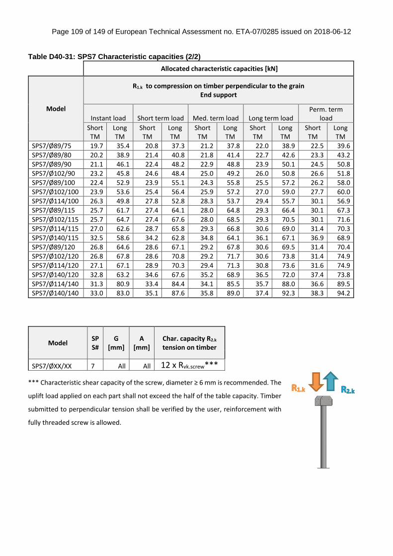
Page 109 of 149 of European Technical Assessment no. ETA-07/0285 issued on 2018-06-12
Table D40-31: SPS7 Characteristic capacities (2/2)
Allocated characteristic capacities [kN]
Model
R1.k to compression on timber perpendicular to the grain End support
Instant load Short term load Med. term load Long term load Perm. term
load
Short TM
Long TM
Short TM
Long TM
Short TM
Long TM
Short TM
Long TM
Short TM
Long TM
SPS7/Ø89/75 19.7 35.4 20.8 37.3 21.2 37.8 22.0 38.9 22.5 39.6
SPS7/Ø89/80 20.2 38.9 21.4 40.8 21.8 41.4 22.7 42.6 23.3 43.2
SPS7/Ø89/90 21.1 46.1 22.4 48.2 22.9 48.8 23.9 50.1 24.5 50.8
SPS7/Ø102/90 23.2 45.8 24.6 48.4 25.0 49.2 26.0 50.8 26.6 51.8
SPS7/Ø89/100 22.4 52.9 23.9 55.1 24.3 55.8 25.5 57.2 26.2 58.0
SPS7/Ø102/100 23.9 53.6 25.4 56.4 25.9 57.2 27.0 59.0 27.7 60.0
SPS7/Ø114/100 26.3 49.8 27.8 52.8 28.3 53.7 29.4 55.7 30.1 56.9
SPS7/Ø89/115 25.7 61.7 27.4 64.1 28.0 64.8 29.3 66.4 30.1 67.3
SPS7/Ø102/115 25.7 64.7 27.4 67.6 28.0 68.5 29.3 70.5 30.1 71.6
SPS7/Ø114/115 27.0 62.6 28.7 65.8 29.3 66.8 30.6 69.0 31.4 70.3
SPS7/Ø140/115 32.5 58.6 34.2 62.8 34.8 64.1 36.1 67.1 36.9 68.9
SPS7/Ø89/120 26.8 64.6 28.6 67.1 29.2 67.8 30.6 69.5 31.4 70.4
SPS7/Ø102/120 26.8 67.8 28.6 70.8 29.2 71.7 30.6 73.8 31.4 74.9
SPS7/Ø114/120 27.1 67.1 28.9 70.3 29.4 71.3 30.8 73.6 31.6 74.9
SPS7/Ø140/120 32.8 63.2 34.6 67.6 35.2 68.9 36.5 72.0 37.4 73.8
SPS7/Ø114/140 31.3 80.9 33.4 84.4 34.1 85.5 35.7 88.0 36.6 89.5
SPS7/Ø140/140 33.0 83.0 35.1 87.6 35.8 89.0 37.4 92.3 38.3 94.2
*** Characteristic shear capacity of the screw, diameter ≥ 6 mm is recommended. The
uplift load applied on each part shall not exceed the half of the table capacity. Timber
submitted to perpendicular tension shall be verified by the user, reinforcement with
fully threaded screw is allowed.
Model SPS#
G [mm]
A [mm]
Char. capacity R2.k tension on timber
SPS7/ØXX/XX 7 All All 12 x Rvk.screw***
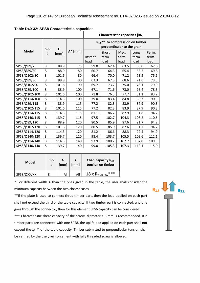
Page 110 of 149 of European Technical Assessment no. ETA-07/0285 issued on 2018-06-12
Table D40-32: SPS8 Characteristic capacities
Characteristic capacities [kN]
Model SPS
# G
[mm] A* [mm]
R1.k** to compression on timber perpendicular to the grain
Instant load
Short term load
Med. term load
Long term load
Perm. term load
SPS8/Ø89/75 8 88.9 75 59.0 62.4 63.5 66.0 67.6
SPS8/Ø89/80 8 88.9 80 60.7 64.3 65.4 68.2 69.8
SPS8/Ø102/80 8 101.6 80 66.4 70.0 71.2 73.9 75.6
SPS8/Ø89/90 8 88.9 90 63.3 67.3 68.6 71.6 73.5
SPS8/Ø102/90 8 101.6 90 69.7 73.7 75.0 78.1 79.9
SPS8/Ø89/100 8 88.9 100 67.1 71.6 73.0 76.4 78.5
SPS8/Ø102/100 8 101.6 100 71.8 76.3 77.7 81.1 83.2
SPS8/Ø114/100 8 114.3 100 79.0 83.4 84.8 88.3 90.3
SPS8/Ø89/115 8 88.9 115 77.2 82.3 83.9 87.9 90.3
SPS8/Ø102/115 8 101.6 115 77.2 82.3 83.9 87.9 90.3
SPS8/Ø114/115 8 114.3 115 81.1 86.2 87.9 91.8 94.2
SPS8/Ø140/115 8 139.7 115 97.5 102.7 104.3 108.2 110.6
SPS8/Ø89/120 8 88.9 120 80.5 85.9 87.6 91.7 94.2
SPS8/Ø102/120 8 101.6 120 80.5 85.9 87.6 91.7 94.2
SPS8/Ø114/120 8 114.3 120 81.2 86.6 88.3 92.4 94.9
SPS8/Ø140/120 8 139.7 120 98.4 103.7 105.5 109.6 112.1
SPS8/Ø114/140 8 114.3 140 93.9 100.2 102.2 107.0 109.9
SPS8/Ø140/140 8 139.7 140 99.0 105.3 107.3 112.1 115.0
* For different width A than the ones given in the table, the user shall consider the
minimum capacity between the two closest cases.
**If the plate is used to connect three timber part, then the load applied on each part
shall not exceed the third of the table capacity. If two timber part is connected, and one
goes through the connector, then for this element SPS6 capacity can be considered
*** Characteristic shear capacity of the screw, diameter ≥ 6 mm is recommended. If n
timber parts are connected with one SPS8, the uplift load applied on each part shall not
exceed the 1/nth of the table capacity. Timber submitted to perpendicular tension shall
be verified by the user, reinforcement with fully threaded screw is allowed.
Model SPS
#
G [mm]
A [mm]
Char. capacity R2.k tension on timber
SPS8/ØXX/XX 8 All All 18 x Rvk.screw***
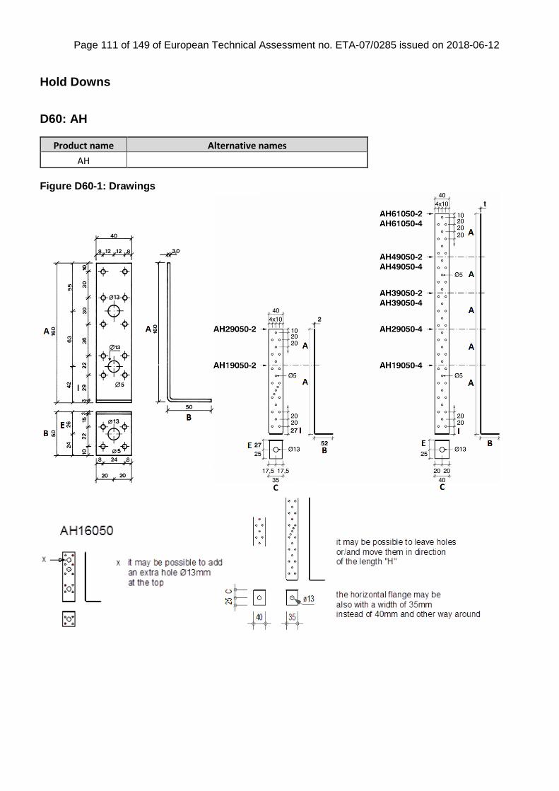
Page 111 of 149 of European Technical Assessment no. ETA-07/0285 issued on 2018-06-12
Hold Downs
D60: AH
Product name Alternative names
AH
Figure D60-1: Drawings
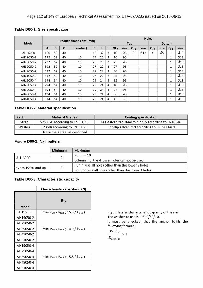
Page 112 of 149 of European Technical Assessment no. ETA-07/0285 issued on 2018-06-12
Table D60-1: Size specification
Model Product dimensions [mm]
Holes
Top Bottom
A B C t (washer) E I t Qty size Qty size Qty size Qty size
AH16050 160 50 40 18 32 3 10 Ø5 3 Ø13 4 Ø5 1 Ø13
AH19050-2 192 52 40 10 25 20 2 16 Ø5 1 Ø13
AH29050-2 292 52 40 10 25 20 2 23 Ø5 1 Ø13
AH39050-2 392 52 40 10 27 22 2 27 Ø5 1 Ø13
AH49050-2 492 52 40 10 27 22 2 36 Ø5 1 Ø13
AH61050-2 612 52 40 10 27 22 2 45 Ø5 1 Ø13
AH19050-4 194 54 40 10 29 24 4 12 Ø5 1 Ø13
AH29050-4 294 54 40 10 29 24 4 18 Ø5 1 Ø13
AH39050-4 394 54 40 10 29 24 4 27 Ø5 1 Ø13
AH49050-4 494 54 40 10 29 24 4 36 Ø5 1 Ø13
AH61050-4 614 54 40 10 29 24 4 45 Ø 1 Ø13
Table D60-2: Material specification
Part Material Grades Coating specification
Strap S250 GD according to EN 10346 Pre-galvanized steel min Z275 according to EN10346
Washer S235JR according to EN 10025 Hot-dip galvanized according to EN ISO 1461
Or stainless steel as described
Figure D60-2: Nail pattern
Minimum Maximum
AH16050 2 Purlin = 10
column = 6, the 4 lower holes cannot be used
types 190xx and up 2 Purlin: use all holes other than the lower 2 holes
Column: use all holes other than the lower 3 holes
Table D60-3: Characteristic capacity
Characteristic capacities [kN]
Model
R1.k
AH16050 min( neff x Rlat.k ; 15.3 / kmod )
AH19050-2
min( neff x Rlat.k ; 14,9 / kmod )
AH29050-2
AH39050-2
AH49050-2
AH61050-2
AH19050-4
min( neff x Rlat.k ; 15.8 / kmod )
AH29050-4
AH39050-4
AH49050-4
AH61050-4
Rlat,k = lateral characteristic capacity of the nail The washer to use is: US40/50/10. It must be checked, that the anchor fulfils the following formula:
13
,
,1
danchor
d
R
F
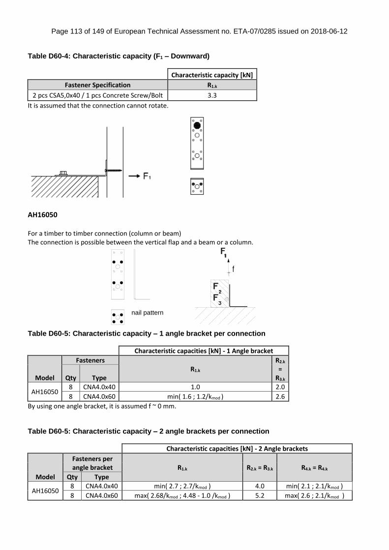
Page 113 of 149 of European Technical Assessment no. ETA-07/0285 issued on 2018-06-12
Table D60-4: Characteristic capacity (F1 – Downward)
Characteristic capacity [kN]
Fastener Specification R1.k
2 pcs CSA5,0x40 / 1 pcs Concrete Screw/Bolt 3.3
It is assumed that the connection cannot rotate.
AH16050 For a timber to timber connection (column or beam) The connection is possible between the vertical flap and a beam or a column. Table D60-5: Characteristic capacity – 1 angle bracket per connection
Characteristic capacities [kN] - 1 Angle bracket
Model
Fasteners R1.k
R2.k =
R3.k Qty Type
AH16050 8 CNA4.0x40 1.0 2.0
8 CNA4.0x60 min( 1.6 ; 1.2/kmod ) 2.6
By using one angle bracket, it is assumed f ~ 0 mm. Table D60-5: Characteristic capacity – 2 angle brackets per connection
Characteristic capacities [kN] - 2 Angle brackets
Model
Fasteners per angle bracket R1.k R2.k = R3.k R4.k = R4.k
Qty Type
AH16050 8 CNA4.0x40 min( 2.7 ; 2.7/kmod ) 4.0 min( 2.1 ; 2.1/kmod )
8 CNA4.0x60 max( 2.68/kmod ; 4.48 - 1.0 /kmod ) 5.2 max( 2.6 ; 2.1/kmod )
nail pattern
f

Page 114 of 149 of European Technical Assessment no. ETA-07/0285 issued on 2018-06-12
D61: AKR
Product name Alternative names
AKR
Figure D61-1: Drawings
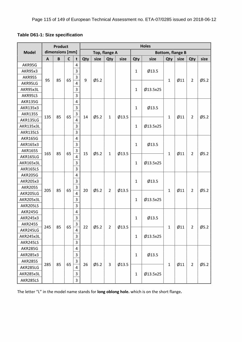
Page 115 of 149 of European Technical Assessment no. ETA-07/0285 issued on 2018-06-12
Table D61-1: Size specification
Model
Product dimensions [mm]
Holes
Top, flange A Bottom, flange B
A B C t Qty size Qty size Qty size Qty size Qty size
AKR95G
95 85 65
4
9 Ø5.2
1 Ø13.5
1 Ø11 2 Ø5.2
AKR95x3 3
AKR95S 3
AKR95LG 4
1 Ø13.5x25 AKR95x3L 3
AKR95LS 3
AKR135G
135 85 65
4
14 Ø5.2 1 Ø13.5
1 Ø13.5
1 Ø11 2 Ø5.2
AKR135x3 3
AKR135S 3
AKR135LG 4
1 Ø13.5x25 AKR135x3L 3
AKR135LS 3
AKR165G
165 85 65
4
15 Ø5.2 1 Ø13.5
1 Ø13.5
1 Ø11 2 Ø5.2
AKR165x3 3
AKR165S 3
AKR165LG 4
1 Ø13.5x25 AKR165x3L 3
AKR165LS 3
AKR205G
205 85 65
4
20 Ø5.2 2 Ø13.5
1 Ø13.5
1 Ø11 2 Ø5.2
AKR205x3 3
AKR205S 3
AKR205LG 4
1 Ø13.5x25 AKR205x3L 3
AKR205LS 3
AKR245G
245 85 65
4
22 Ø5.2 2 Ø13.5
1 Ø13.5
1 Ø11 2 Ø5.2
AKR245x3 3
AKR245S 3
AKR245LG 4
1 Ø13.5x25 AKR245x3L 3
AKR245LS 3
AKR285G
285 85 65
4
26 Ø5.2 3 Ø13.5
1 Ø13.5
1 Ø11 2 Ø5.2
AKR285x3 3
AKR285S 3
AKR285LG 4
1 Ø13.5x25 AKR285x3L 3
AKR285LS 3
The letter “L” in the model name stands for long oblong hole. which is on the short flange.
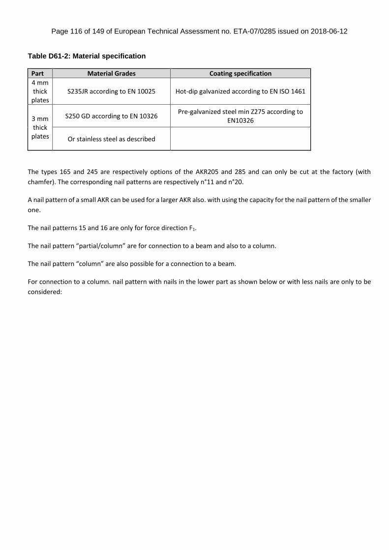
Page 116 of 149 of European Technical Assessment no. ETA-07/0285 issued on 2018-06-12
Table D61-2: Material specification
Part Material Grades Coating specification
4 mm thick
plates S235JR according to EN 10025 Hot-dip galvanized according to EN ISO 1461
3 mm thick
plates
S250 GD according to EN 10326 Pre-galvanized steel min Z275 according to
EN10326
Or stainless steel as described
The types 165 and 245 are respectively options of the AKR205 and 285 and can only be cut at the factory (with
chamfer). The corresponding nail patterns are respectively n°11 and n°20.
A nail pattern of a small AKR can be used for a larger AKR also. with using the capacity for the nail pattern of the smaller
one.
The nail patterns 15 and 16 are only for force direction F1.
The nail pattern “partial/column” are for connection to a beam and also to a column.
The nail pattern “column” are also possible for a connection to a beam.
For connection to a column. nail pattern with nails in the lower part as shown below or with less nails are only to be
considered:
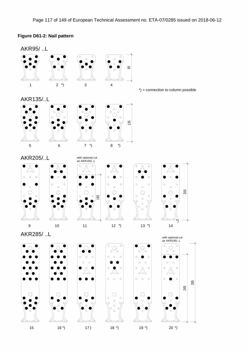
Page 117 of 149 of European Technical Assessment no. ETA-07/0285 issued on 2018-06-12
Figure D61-2: Nail pattern
AKR95/ ..L
AKR135/..L
AKR285/ ..L
AKR205/..L
205
165
245
135
95
285
with optional cut
*) *)
*)
*) *) *) *) *)
*) *)
*)
*) = connection to column possible
2 31 4
875 6
141312119 10
201918171615
as AKR165/..L
as AKR245/..Lwith optional cut
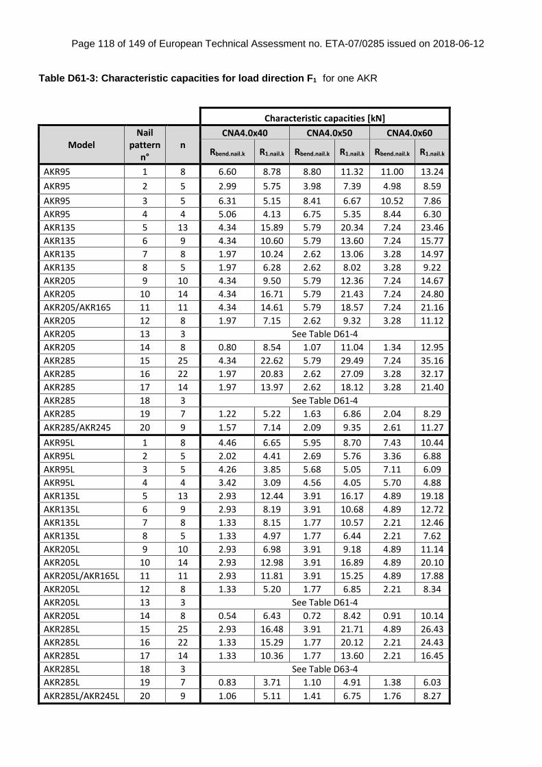
Page 118 of 149 of European Technical Assessment no. ETA-07/0285 issued on 2018-06-12
Table D61-3: Characteristic capacities for load direction F1 for one AKR
Characteristic capacities [kN]
Model Nail
pattern n°
n CNA4.0x40 CNA4.0x50 CNA4.0x60
Rbend.nail.k R1.nail.k Rbend.nail.k R1.nail.k Rbend.nail.k R1.nail.k
AKR95 1 8 6.60 8.78 8.80 11.32 11.00 13.24
AKR95 2 5 2.99 5.75 3.98 7.39 4.98 8.59
AKR95 3 5 6.31 5.15 8.41 6.67 10.52 7.86
AKR95 4 4 5.06 4.13 6.75 5.35 8.44 6.30
AKR135 5 13 4.34 15.89 5.79 20.34 7.24 23.46
AKR135 6 9 4.34 10.60 5.79 13.60 7.24 15.77
AKR135 7 8 1.97 10.24 2.62 13.06 3.28 14.97
AKR135 8 5 1.97 6.28 2.62 8.02 3.28 9.22
AKR205 9 10 4.34 9.50 5.79 12.36 7.24 14.67
AKR205 10 14 4.34 16.71 5.79 21.43 7.24 24.80
AKR205/AKR165 11 11 4.34 14.61 5.79 18.57 7.24 21.16
AKR205 12 8 1.97 7.15 2.62 9.32 3.28 11.12
AKR205 13 3 See Table D61-4
AKR205 14 8 0.80 8.54 1.07 11.04 1.34 12.95
AKR285 15 25 4.34 22.62 5.79 29.49 7.24 35.16
AKR285 16 22 1.97 20.83 2.62 27.09 3.28 32.17
AKR285 17 14 1.97 13.97 2.62 18.12 3.28 21.40
AKR285 18 3 See Table D61-4
AKR285 19 7 1.22 5.22 1.63 6.86 2.04 8.29
AKR285/AKR245 20 9 1.57 7.14 2.09 9.35 2.61 11.27
AKR95L 1 8 4.46 6.65 5.95 8.70 7.43 10.44
AKR95L 2 5 2.02 4.41 2.69 5.76 3.36 6.88
AKR95L 3 5 4.26 3.85 5.68 5.05 7.11 6.09
AKR95L 4 4 3.42 3.09 4.56 4.05 5.70 4.88
AKR135L 5 13 2.93 12.44 3.91 16.17 4.89 19.18
AKR135L 6 9 2.93 8.19 3.91 10.68 4.89 12.72
AKR135L 7 8 1.33 8.15 1.77 10.57 2.21 12.46
AKR135L 8 5 1.33 4.97 1.77 6.44 2.21 7.62
AKR205L 9 10 2.93 6.98 3.91 9.18 4.89 11.14
AKR205L 10 14 2.93 12.98 3.91 16.89 4.89 20.10
AKR205L/AKR165L 11 11 2.93 11.81 3.91 15.25 4.89 17.88
AKR205L 12 8 1.33 5.20 1.77 6.85 2.21 8.34
AKR205L 13 3 See Table D61-4
AKR205L 14 8 0.54 6.43 0.72 8.42 0.91 10.14
AKR285L 15 25 2.93 16.48 3.91 21.71 4.89 26.43
AKR285L 16 22 1.33 15.29 1.77 20.12 2.21 24.43
AKR285L 17 14 1.33 10.36 1.77 13.60 2.21 16.45
AKR285L 18 3 See Table D63-4
AKR285L 19 7 0.83 3.71 1.10 4.91 1.38 6.03
AKR285L/AKR245L 20 9 1.06 5.11 1.41 6.75 1.76 8.27

Page 119 of 149 of European Technical Assessment no. ETA-07/0285 issued on 2018-06-12
n = number of nails according to the nail pattern
For an AKR with a thickness of 4.0mm:
knailbend
knail
kR
k
kN
R
R,,
mod
,,1
,1 43,21min
For an AKR with a thickness of 3.0mm:
knailbend
knail
kR
k
kN
R
R,,
mod
,,1
,1 52,12min with R1.nail.k and Rbend.nail.k are given in the
table before. The force shall act in the middle of the beam/column. or the eccentricity may be overcome by clamping or an extra calculated force F4 shall be considered. The values are also applicable for a connection with a gap between the short flange of the AKR and the bearing. for F1 load direction only. The bolt shall have a capacity to sustain an axial force of F1.d. Instead of bolts also timber screws with washers can be applied to the bottom leg for a pure uplift force connection. Table D61-4: Characteristic capacities for load direction F1 for nail pattern 13 and 18. for one AKR:
Characteristic capacity governed by nails: n=3 nails [kN]
R1.nail.k
Nails type AKR type AKR…L
h= 73 113 153 73 113 153
CNA4.0x40 3.35 3.83 4.17 2.55 3.04 3.44
CNA4.0x50 4.32 4.88 5.28 3.33 3.94 4.42
CNA4.0x60 5.04 5.60 5.97 3.99 4.65 5.15
h = place of the lowermost nail above the line "b". Nail pattern 13: h=73mm. nail pattern 18: h=113mm
Characteristic capacity governed by steel [kN]
RF.1.i.k [kN]
AKR205 4.89
AKR285 4.02
AKR205L 3.30
AKR285L 2.72
RF1.i.k is based on the bending With i = h
R1.k= min(R1.nail.k;RF.1.i.k ) The capacity R1.nail.i.k shall be calculated as design capacity with the current kmod . the capacity RF1.i.k shall be calculated with kmod= 1.0 for all load durations.
gap
h=73
0
83
b
h = distance of the lowermost nail to line b
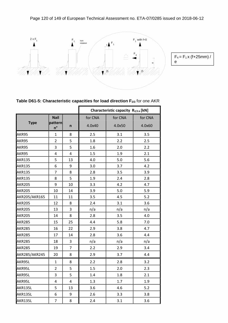
Page 120 of 149 of European Technical Assessment no. ETA-07/0285 issued on 2018-06-12
Table D61-5: Characteristic capacities for load direction F2/3 for one AKR
Characteristic capacity R2/3.k [kN]
Type Nail
pattern n°
for CNA for CNA for CNA
n 4.0x40 4.0x50 4.0x60
AKR95 1 8 2.5 3.1 3.5
AKR95 2 5 1.8 2.2 2.5
AKR95 3 5 1.6 2.0 2.2
AKR95 4 4 1.5 1.9 2.1
AKR135 5 13 4.0 5.0 5.6
AKR135 6 9 3.0 3.7 4.2
AKR135 7 8 2.8 3.5 3.9
AKR135 8 5 1.9 2.4 2.8
AKR205 9 10 3.3 4.2 4.7
AKR205 10 14 3.9 5.0 5.9
AKR205/AKR165 11 11 3.5 4.5 5.2
AKR205 12 8 2.4 3.1 3.6
AKR205 13 3 n/a n/a n/a
AKR205 14 8 2.8 3.5 4.0
AKR285 15 25 4.4 5.8 7.0
AKR285 16 22 2.9 3.8 4.7
AKR285 17 14 2.8 3.6 4.4
AKR285 18 3 n/a n/a n/a
AKR285 19 7 2.2 2.9 3.4
AKR285/AKR245 20 8 2.9 3.7 4.4
AKR95L 1 8 2.2 2.8 3.2
AKR95L 2 5 1.5 2.0 2.3
AKR95L 3 5 1.4 1.8 2.1
AKR95L 4 4 1.3 1.7 1.9
AKR135L 5 13 3.6 4.6 5.2
AKR135L 6 9 2.6 3.3 3.8
AKR135L 7 8 2.4 3.1 3.6
F4
F with f=01
1F
2 x F1 F
1
f
e
25 25
non rotation
F4 = F1 x (f+25mm) / e
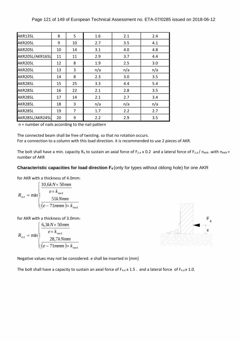
Page 121 of 149 of European Technical Assessment no. ETA-07/0285 issued on 2018-06-12
AKR135L 8 5 1.6 2.1 2.4
AKR205L 9 10 2.7 3.5 4.1
AKR205L 10 14 3.1 4.0 4.8
AKR205L/AKR165L 11 11 2.9 3.7 4.4
AKR205L 12 8 1.9 2.5 3.0
AKR205L 13 3 n/a n/a n/a
AKR205L 14 8 2.3 3.0 3.5
AKR285L 15 25 3.3 4.4 5.4
AKR285L 16 22 2.1 2.8 3.5
AKR285L 17 14 2.1 2.7 3.4
AKR285L 18 3 n/a n/a n/a
AKR285L 19 7 1.7 2.2 2.7
AKR285L/AKR245L 20 9 2.2 2.9 3.5
n = number of nails according to the nail pattern The connected beam shall be free of twisting. so that no rotation occurs. For a connection to a column with this load direction. it is recommended to use 2 pieces of AKR. The bolt shall have a min. capacity Rd to sustain an axial force of F2.d x 0.2 and a lateral force of F2.d / nAKR .with nAKR = number of AKR Characteristic capacities for load direction F4 (only for types without oblong hole) for one AKR for AKR with a thickness of 4.0mm:
mod
mod
,4
71
51
506,10
min
kmmme
kNmm
ke
mmkN
R k
for AKR with a thickness of 3.0mm:
mod
mod
,4
71
7,28
503,6
min
kmmme
kNmm
ke
mmkN
R k
Negative values may not be considered. e shall be inserted in [mm] The bolt shall have a capacity to sustain an axial force of F4.d x 1.5 . and a lateral force of F4.d x 1.0.
e
F4
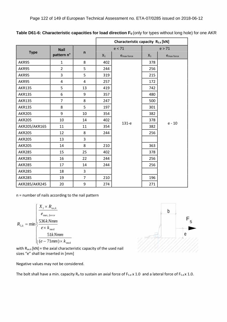
Page 122 of 149 of European Technical Assessment no. ETA-07/0285 issued on 2018-06-12
Table D61-6: Characteristic capacities for load direction F5 (only for types without long hole) for one AKR
Characteristic capacity R5.k [kN]
Type Nail
pattern n° n
e < 71 e > 71
X1 emax force X1 emax force
AKR95 1 8 402
131-e
378
e - 10
AKR95 2 5 244 256
AKR95 3 5 319 215
AKR95 4 4 257 172
AKR135 5 13 419 742
AKR135 6 9 357 480
AKR135 7 8 247 500
AKR135 8 5 197 301
AKR205 9 10 354 382
AKR205 10 14 402 378
AKR205/AKR165 11 11 354 382
AKR205 12 8 244 256
AKR205 13 3
AKR205 14 8 210 363
AKR285 15 25 402 378
AKR285 16 22 244 256
AKR285 17 14 244 256
AKR285 18 3
AKR285 19 7 210 196
AKR285/AKR245 20 9 274 271
n = number of nails according to the nail pattern
mod
mod
max,
,1
,5
)71(
51
536min
kmme
kNmm
ke
kNmm
e
RX
R
force
kax
k
with Rax.k [kN] = the axial characteristic capacity of the used nail sizes “e” shall be inserted in [mm] Negative values may not be considered. The bolt shall have a min. capacity Rd to sustain an axial force of F5.d x 1.0 and a lateral force of F5.d x 1.0.
F5
e
b
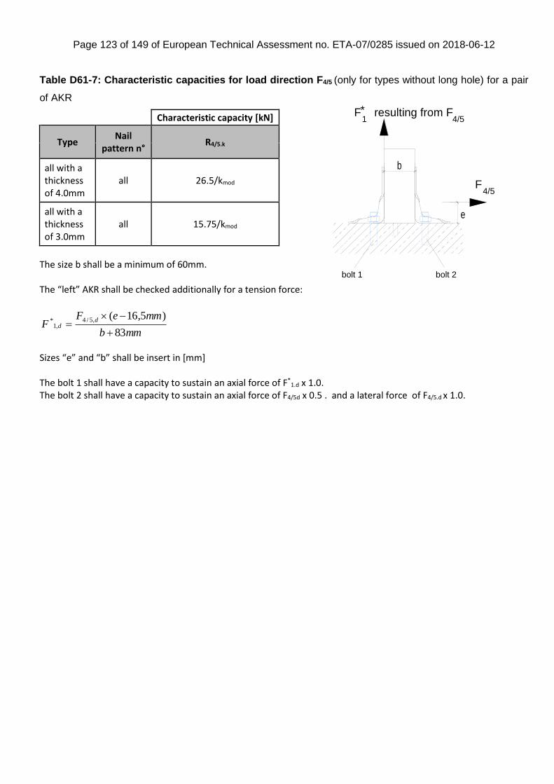
Page 123 of 149 of European Technical Assessment no. ETA-07/0285 issued on 2018-06-12
Table D61-7: Characteristic capacities for load direction F4/5 (only for types without long hole) for a pair
of AKR
Characteristic capacity [kN]
Type Nail
pattern n° R4/5.k
all with a thickness of 4.0mm
all 26.5/kmod
all with a thickness of 3.0mm
all 15.75/kmod
The size b shall be a minimum of 60mm. The “left” AKR shall be checked additionally for a tension force:
mmb
mmeFF
dd
83
)5,16(,5/4,1
*
Sizes “e” and “b” shall be insert in [mm] The bolt 1 shall have a capacity to sustain an axial force of F*
1.d x 1.0. The bolt 2 shall have a capacity to sustain an axial force of F4/5d x 0.5 . and a lateral force of F4/5.d x 1.0.
F4/5
e
b
F1
resulting from F4/5
*
bolt 1 bolt 2
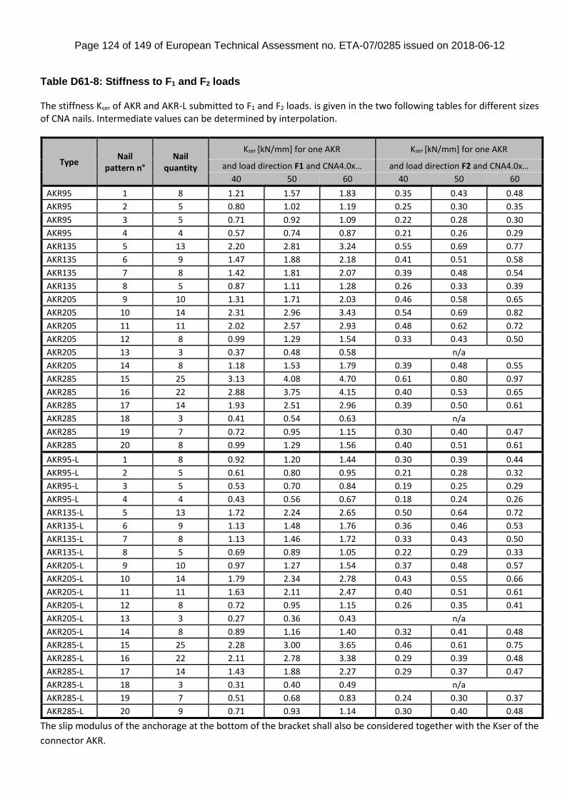
Page 124 of 149 of European Technical Assessment no. ETA-07/0285 issued on 2018-06-12
Table D61-8: Stiffness to F1 and F2 loads The stiffness Kser of AKR and AKR-L submitted to F1 and F2 loads. is given in the two following tables for different sizes of CNA nails. Intermediate values can be determined by interpolation.
Type Nail
pattern n° Nail
quantity
Kser [kN/mm] for one AKR Kser [kN/mm] for one AKR
and load direction F1 and CNA4.0x… and load direction F2 and CNA4.0x…
40 50 60 40 50 60
AKR95 1 8 1.21 1.57 1.83 0.35 0.43 0.48
AKR95 2 5 0.80 1.02 1.19 0.25 0.30 0.35
AKR95 3 5 0.71 0.92 1.09 0.22 0.28 0.30
AKR95 4 4 0.57 0.74 0.87 0.21 0.26 0.29
AKR135 5 13 2.20 2.81 3.24 0.55 0.69 0.77
AKR135 6 9 1.47 1.88 2.18 0.41 0.51 0.58
AKR135 7 8 1.42 1.81 2.07 0.39 0.48 0.54
AKR135 8 5 0.87 1.11 1.28 0.26 0.33 0.39
AKR205 9 10 1.31 1.71 2.03 0.46 0.58 0.65
AKR205 10 14 2.31 2.96 3.43 0.54 0.69 0.82
AKR205 11 11 2.02 2.57 2.93 0.48 0.62 0.72
AKR205 12 8 0.99 1.29 1.54 0.33 0.43 0.50
AKR205 13 3 0.37 0.48 0.58 n/a
AKR205 14 8 1.18 1.53 1.79 0.39 0.48 0.55
AKR285 15 25 3.13 4.08 4.70 0.61 0.80 0.97
AKR285 16 22 2.88 3.75 4.15 0.40 0.53 0.65
AKR285 17 14 1.93 2.51 2.96 0.39 0.50 0.61
AKR285 18 3 0.41 0.54 0.63 n/a
AKR285 19 7 0.72 0.95 1.15 0.30 0.40 0.47
AKR285 20 8 0.99 1.29 1.56 0.40 0.51 0.61
AKR95-L 1 8 0.92 1.20 1.44 0.30 0.39 0.44
AKR95-L 2 5 0.61 0.80 0.95 0.21 0.28 0.32
AKR95-L 3 5 0.53 0.70 0.84 0.19 0.25 0.29
AKR95-L 4 4 0.43 0.56 0.67 0.18 0.24 0.26
AKR135-L 5 13 1.72 2.24 2.65 0.50 0.64 0.72
AKR135-L 6 9 1.13 1.48 1.76 0.36 0.46 0.53
AKR135-L 7 8 1.13 1.46 1.72 0.33 0.43 0.50
AKR135-L 8 5 0.69 0.89 1.05 0.22 0.29 0.33
AKR205-L 9 10 0.97 1.27 1.54 0.37 0.48 0.57
AKR205-L 10 14 1.79 2.34 2.78 0.43 0.55 0.66
AKR205-L 11 11 1.63 2.11 2.47 0.40 0.51 0.61
AKR205-L 12 8 0.72 0.95 1.15 0.26 0.35 0.41
AKR205-L 13 3 0.27 0.36 0.43 n/a
AKR205-L 14 8 0.89 1.16 1.40 0.32 0.41 0.48
AKR285-L 15 25 2.28 3.00 3.65 0.46 0.61 0.75
AKR285-L 16 22 2.11 2.78 3.38 0.29 0.39 0.48
AKR285-L 17 14 1.43 1.88 2.27 0.29 0.37 0.47
AKR285-L 18 3 0.31 0.40 0.49 n/a
AKR285-L 19 7 0.51 0.68 0.83 0.24 0.30 0.37
AKR285-L 20 9 0.71 0.93 1.14 0.30 0.40 0.48
The slip modulus of the anchorage at the bottom of the bracket shall also be considered together with the Kser of the
connector AKR.
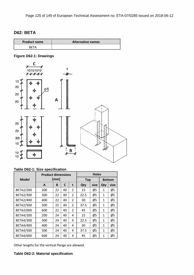
Page 125 of 149 of European Technical Assessment no. ETA-07/0285 issued on 2018-06-12
D62: BETA
Product name Alternative names
BETA
Figure D62-1: Drawings
Table D62-1: Size specification
Model
Product dimensions [mm]
Holes
Top Bottom
A B C t Qty size Qty size
BETA2/200 200 22 40 2 15 Ø5 1 Ø5
BETA2/300 300 22 40 2 22.5 Ø5 1 Ø5
BETA2/400 400 22 40 2 30 Ø5 1 Ø5
BETA2/500 500 22 40 2 37.5 Ø5 1 Ø5
BETA2/600 600 22 40 2 45 Ø5 1 Ø5
BETA4/200 200 24 40 4 15 Ø5 1 Ø5
BETA4/300 300 24 40 4 22.5 Ø5 1 Ø5
BETA4/400 400 24 40 4 30 Ø5 1 Ø5
BETA4/500 500 24 40 4 37.5 Ø5 1 Ø5
BETA4/600 600 24 40 4 45 Ø5 1 Ø5
Other lengths for the vertical flange are allowed. Table D62-2: Material specification
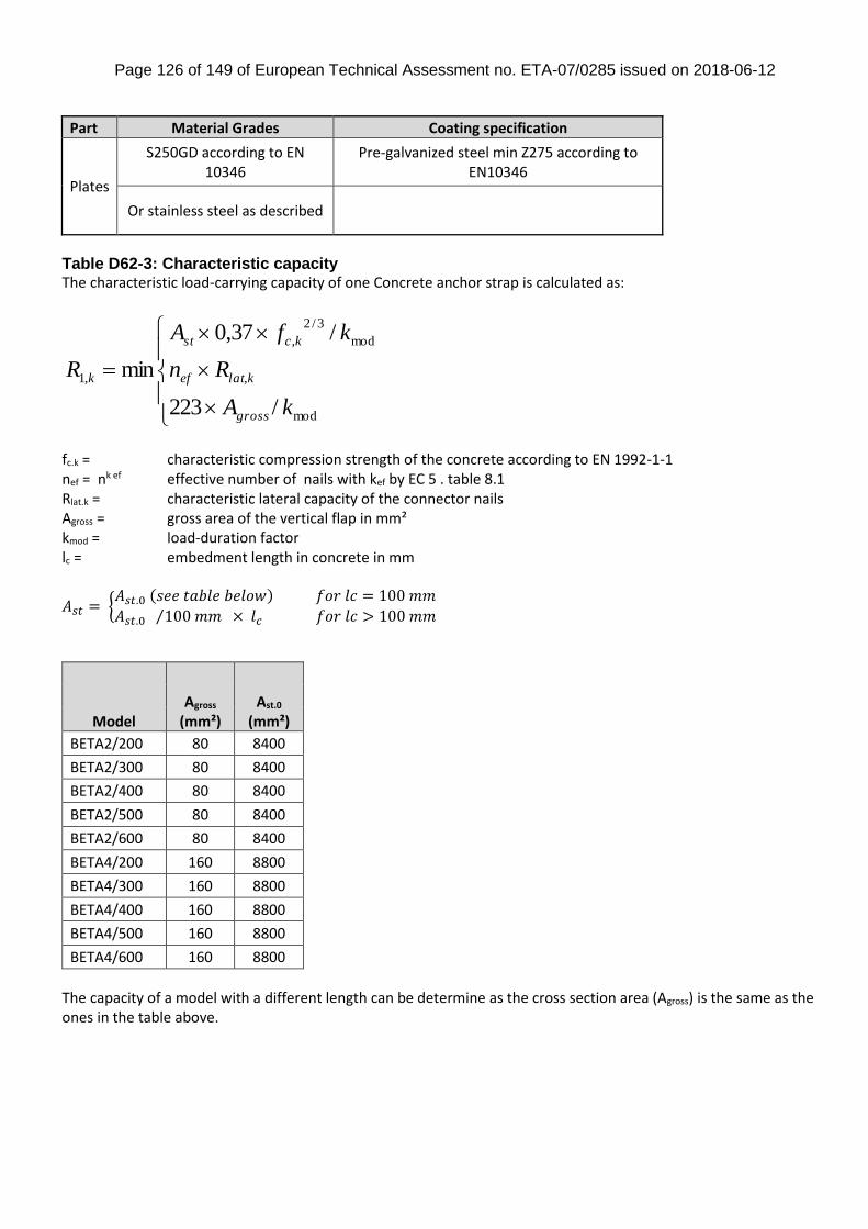
Page 126 of 149 of European Technical Assessment no. ETA-07/0285 issued on 2018-06-12
Part Material Grades Coating specification
Plates
S250GD according to EN 10346
Pre-galvanized steel min Z275 according to EN10346
Or stainless steel as described
Table D62-3: Characteristic capacity The characteristic load-carrying capacity of one Concrete anchor strap is calculated as:
mod
,
mod
3/2
,
,1
/223
/37,0
min
kA
Rn
kfA
R
gross
klatef
kcst
k
fc.k = characteristic compression strength of the concrete according to EN 1992-1-1 nef = nk ef effective number of nails with kef by EC 5 . table 8.1 Rlat.k = characteristic lateral capacity of the connector nails Agross = gross area of the vertical flap in mm² kmod = load-duration factor lc = embedment length in concrete in mm
𝐴𝑠𝑡 = {𝐴𝑠𝑡.0 (𝑠𝑒𝑒 𝑡𝑎𝑏𝑙𝑒 𝑏𝑒𝑙𝑜𝑤) 𝑓𝑜𝑟 𝑙𝑐 = 100 𝑚𝑚
𝐴𝑠𝑡.0 100 𝑚𝑚⁄ × 𝑙𝑐 𝑓𝑜𝑟 𝑙𝑐 > 100 𝑚𝑚
Model Agross
(mm²) Ast.0
(mm²)
BETA2/200 80 8400
BETA2/300 80 8400
BETA2/400 80 8400
BETA2/500 80 8400
BETA2/600 80 8400
BETA4/200 160 8800
BETA4/300 160 8800
BETA4/400 160 8800
BETA4/500 160 8800
BETA4/600 160 8800
The capacity of a model with a different length can be determine as the cross section area (Agross) is the same as the ones in the table above.
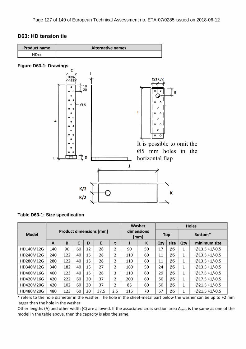
Page 127 of 149 of European Technical Assessment no. ETA-07/0285 issued on 2018-06-12
D63: HD tension tie
Product name Alternative names
HDxx
Figure D63-1: Drawings
Table D63-1: Size specification
Model Product dimensions [mm]
Washer dimensions
[mm]
Holes
Top Bottom*
A B C D E t J K Qty size Qty minimum size
HD140M12G 140 90 60 12 28 2 90 50 17 Ø5 1 Ø13.5 +1/-0.5
HD240M12G 240 122 40 15 28 2 110 60 11 Ø5 1 Ø13.5 +1/-0.5
HD280M12G 280 122 40 15 28 2 110 60 11 Ø5 1 Ø13.5 +1/-0.5
HD340M12G 340 182 40 15 27 2 160 50 24 Ø5 1 Ø13.5 +1/-0.5
HD400M16G 400 123 40 15 28 3 110 60 29 Ø5 1 Ø17.5 +1/-0.5
HD420M16G 420 222 60 20 37 2 200 60 50 Ø5 1 Ø17.5 +1/-0.5
HD420M20G 420 102 60 20 37 2 85 60 50 Ø5 1 Ø21.5 +1/-0.5
HD480M20G 480 123 60 20 37.5 2.5 115 70 57 Ø5 1 Ø21.5 +1/-0.5
* refers to the hole diameter in the washer. The hole in the sheet-metal part below the washer can be up to +2 mm larger than the hole in the washer Other lengths (A) and other width (C) are allowed. If the associated cross section area Agross is the same as one of the model in the table above. then the capacity is also the same.
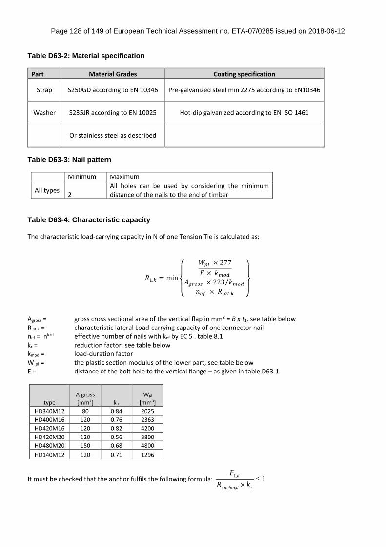
Page 128 of 149 of European Technical Assessment no. ETA-07/0285 issued on 2018-06-12
Table D63-2: Material specification
Part Material Grades Coating specification
Strap S250GD according to EN 10346 Pre-galvanized steel min Z275 according to EN10346
Washer S235JR according to EN 10025 Hot-dip galvanized according to EN ISO 1461
Or stainless steel as described
Table D63-3: Nail pattern
Minimum Maximum
All types 2
All holes can be used by considering the minimum distance of the nails to the end of timber
Table D63-4: Characteristic capacity The characteristic load-carrying capacity in N of one Tension Tie is calculated as:
𝑅1.𝑘 = min
{
𝑊𝑝𝑙 × 277
𝐸 × 𝑘𝑚𝑜𝑑𝐴𝑔𝑟𝑜𝑠𝑠 × 223 𝑘𝑚𝑜𝑑⁄
𝑛𝑒𝑓 × 𝑅𝑙𝑎𝑡.𝑘 }
Agross = gross cross sectional area of the vertical flap in mm² = B x t1. see table below Rlat.k = characteristic lateral Load-carrying capacity of one connector nail nef = nk ef effective number of nails with kef by EC 5 . table 8.1 kr = reduction factor. see table below kmod = load-duration factor W pl = the plastic section modulus of the lower part; see table below E = distance of the bolt hole to the vertical flange – as given in table D63-1
type
A gross [mm²]
k r
Wpl [mm³]
HD340M12 80 0.84 2025
HD400M16 120 0.76 2363
HD420M16 120 0.82 4200
HD420M20 120 0.56 3800
HD480M20 150 0.68 4800
HD140M12 120 0.71 1296
It must be checked that the anchor fulfils the following formula: 1,
,1
rdanchor
d
kR
F
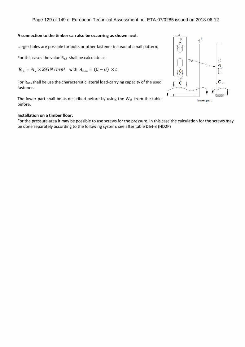
Page 129 of 149 of European Technical Assessment no. ETA-07/0285 issued on 2018-06-12
A connection to the timber can also be occurring as shown next: Larger holes are possible for bolts or other fastener instead of a nail pattern. For this cases the value R1.k shall be calculate as:
²/295,1 mmNAR netk with 𝐴𝑛𝑒𝑡 = (𝐶 − 𝐺) × 𝑡
For Rlat.k shall be use the characteristic lateral load-carrying capacity of the used fastener. The lower part shall be as described before by using the Wpl from the table before. Installation on a timber floor: For the pressure area it may be possible to use screws for the pressure. In this case the calculation for the screws may be done separately according to the following system: see after table D64-3 (HD2P)
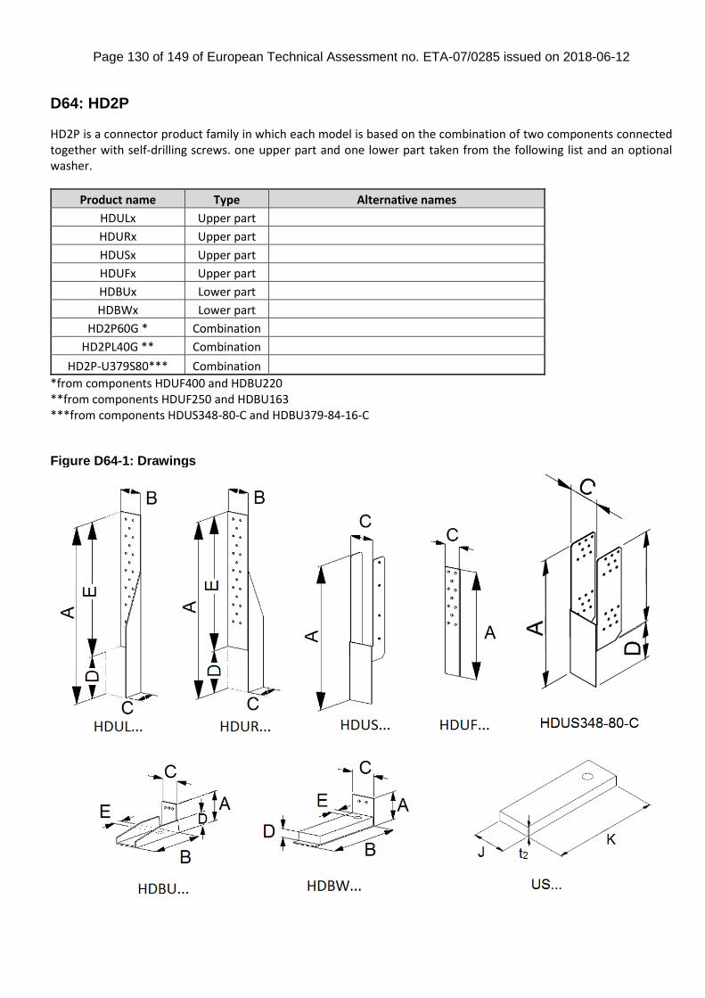
Page 130 of 149 of European Technical Assessment no. ETA-07/0285 issued on 2018-06-12
D64: HD2P
HD2P is a connector product family in which each model is based on the combination of two components connected together with self-drilling screws. one upper part and one lower part taken from the following list and an optional washer.
Product name Type Alternative names
HDULx Upper part
HDURx Upper part
HDUSx Upper part
HDUFx Upper part
HDBUx Lower part
HDBWx Lower part
HD2P60G * Combination
HD2PL40G ** Combination
HD2P-U379S80*** Combination
*from components HDUF400 and HDBU220 **from components HDUF250 and HDBU163 ***from components HDUS348-80-C and HDBU379-84-16-C Figure D64-1: Drawings
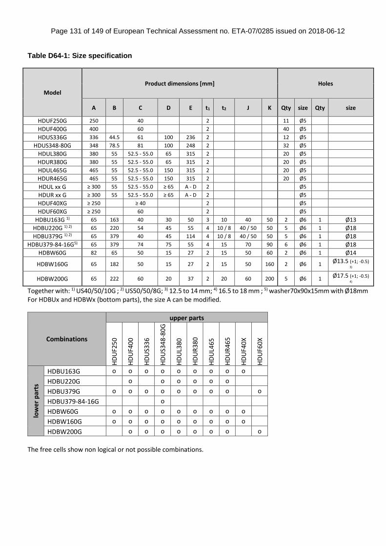
Page 131 of 149 of European Technical Assessment no. ETA-07/0285 issued on 2018-06-12
Table D64-1: Size specification
Model
Product dimensions [mm] Holes
A B C D E t1 t2 J K Qty size Qty size
HDUF250G 250 40 2 11 Ø5
HDUF400G 400 60 2 40 Ø5
HDUS336G 336 44.5 61 100 236 2 12 Ø5
HDUS348-80G 348 78.5 81 100 248 2 32 Ø5
HDUL380G 380 55 52.5 - 55.0 65 315 2 20 Ø5
HDUR380G 380 55 52.5 - 55.0 65 315 2 20 Ø5
HDUL465G 465 55 52.5 - 55.0 150 315 2 20 Ø5
HDUR465G 465 55 52.5 - 55.0 150 315 2 20 Ø5
HDUL xx G ≥ 300 55 52.5 - 55.0 ≥ 65 A - D 2 Ø5
HDUR xx G ≥ 300 55 52.5 - 55.0 ≥ 65 A - D 2 Ø5
HDUF40XG ≥ 250 ≥ 40 2 Ø5
HDUF60XG ≥ 250 60 2 Ø5
HDBU163G 1) 65 163 40 30 50 3 10 40 50 2 Ø6 1 Ø13
HDBU220G 1) 2) 65 220 54 45 55 4 10 / 8 40 / 50 50 5 Ø6 1 Ø18
HDBU379G 1) 2) 65 379 40 45 114 4 10 / 8 40 / 50 50 5 Ø6 1 Ø18
HDBU379-84-16G5) 65 379 74 75 55 4 15 70 90 6 Ø6 1 Ø18
HDBW60G 82 65 50 15 27 2 15 50 60 2 Ø6 1 Ø14
HDBW160G 65 182 50 15 27 2 15 50 160 2 Ø6 1 Ø13.5 (+1; -0.5) 3)
HDBW200G 65 222 60 20 37 2 20 60 200 5 Ø6 1 Ø17.5 (+1; -0.5) 4)
Together with: 1) US40/50/10G ; 2) US50/50/8G; 3) 12.5 to 14 mm; 4) 16.5 to 18 mm ; 5) washer70x90x15mm with Ø18mm For HDBUx and HDBWx (bottom parts), the size A can be modified.
Combinations
upper parts
HD
UF2
50
HD
UF4
00
HD
US3
36
HD
US3
48
-80
G
HD
UL3
80
HD
UR
380
HD
UL4
65
HD
UR
465
HD
UF4
0X
HD
UF6
0X
low
er p
arts
HDBU163G o o o o o o o o o
HDBU220G o o o o o o
HDBU379G o o o o o o o o o
HDBU379-84-16G o
HDBW60G o o o o o o o o o
HDBW160G o o o o o o o o o
HDBW200G o o o o o o o o
The free cells show non logical or not possible combinations.

Page 132 of 149 of European Technical Assessment no. ETA-07/0285 issued on 2018-06-12
Table D64-2: Material specification
Part Material Grades Coating specification
Plates S250 GD according to EN 10346 Pre-galvanized steel min Z275 according to EN10346
Washer S235JR according to EN 10025:2004 Hot-dip galvanized according to EN ISO 1461:1999
Or stainless steel as described
Figure D64-2: Nail pattern for HDUS and HDUL/R
Minimum Maximum
HDUF 2
All holes can be used by considering the minimum distance of the nails to the end of the timber
HDUS Partial nailing 2x4 nails full nailing 2x6 nails
HDUL/R Partial nailing 14 nails full nailing 20 nails
HDUS348-80G
2x6 nails on extreme rows. Then nail holes shall be filled symmetrically starting from top and bottom rows
full nailing 2x16 nails
Table D64-3: Characteristic capacity The capacity of a combination of an upper and lower part is given by the lower capacity between the two parts given in the following tables. Also the capacity of the anchor shall be checked by using the following formula:
With: Rbolt.k = characteristic withdrawal capacity of the (anchor)-bolt in kN kr = factor to calculate the force in the bolt, given in the following tables F1.d = Design load applied to the connector.
full- partial-
nailing
full- partial- nailing
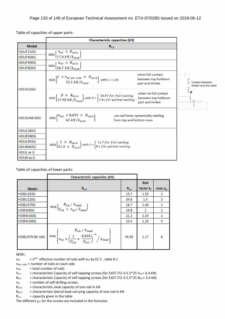
Page 133 of 149 of European Technical Assessment no. ETA-07/0285 issued on 2018-06-12
Table of capacities of upper parts:
Table of capacities of lower parts:
With: nef = nkef effective number of nails with kef by EC 5 . table 8.1 nper.-side = number of nails on each side ntot = total number of nails Vs.k = characteristic Capacity of self-tapping screws (for EJOT JT2-3-5.5*25 VS.k= 6.4 kN) Ns.k = characteristic Capacity of self-tapping screws (for EJOT JT2-3-5.5*25 NS.k= 3.4 kN) nsc = number of self-drilling screws Rax.k = characteristic axial capacity of one nail in kN Rlat.k = characteristic lateral load-carrying capacity of one nail in kN Rs.k = capacity given in the table The different γm for the screws are included in the formulas
contact betweentimber and the steel
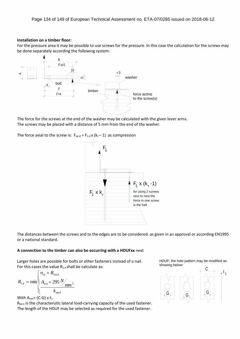
Page 134 of 149 of European Technical Assessment no. ETA-07/0285 issued on 2018-06-12
Installation on a timber floor: For the pressure area it may be possible to use screws for the pressure. In this case the calculation for the screws may be done separately according the following system:
The force for the screws at the end of the washer may be calculated with the given lever arms. The screws may be placed with a distance of 5 mm from the end of the washer. The force axial to the screw is: Fax.d = F1.d x (kr – 1) as compression
The distances between the screws and to the edges are to be considered. as given in an approval or according EN1995 or a national standard. A connection to the timber can also be occurring with a HDUFxx next Larger holes are possible for bolts or other fasteners instead of a nail. For this cases the value R1.k shall be calculate as:
With Anet= (C-G) x t1 Rlat.k is the characteristic lateral load-carrying capacity of the used fastener. The length of the HDUF may be selected as required for the used fastener.
B
D
A
F
10
F-a-5
a
F+4
< 5
bolt
timber
washer
force actingto the screw(s)
F1
F x k1 r
F x (k -1)1 r
for using 2 screws
next to next the
force in one screw
is the half
mod
2
,
,1 295min
k
mmNA
Rn
Rnet
klatef
k
1t
GGG
C
HDUF: the hole pattern may be modified as showing below:
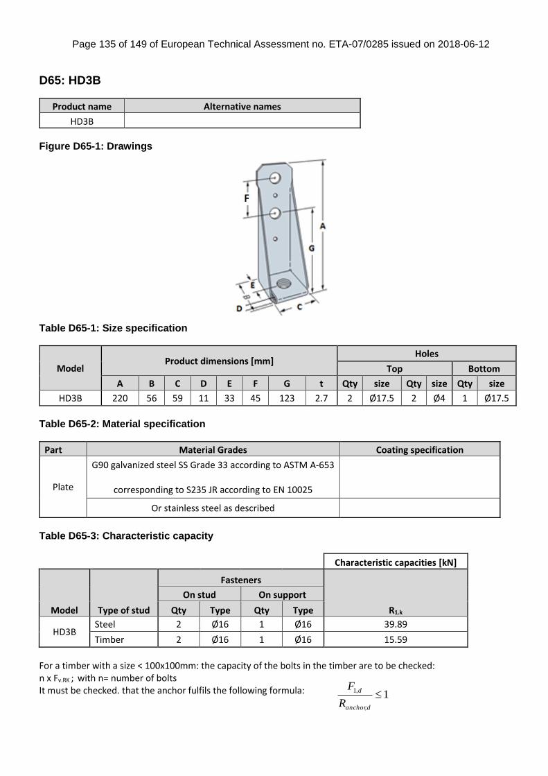
Page 135 of 149 of European Technical Assessment no. ETA-07/0285 issued on 2018-06-12
1,
,1
danchor
d
R
F
D65: HD3B
Product name Alternative names
HD3B
Figure D65-1: Drawings
Table D65-1: Size specification
Model Product dimensions [mm]
Holes
Top Bottom
A B C D E F G t Qty size Qty size Qty size
HD3B 220 56 59 11 33 45 123 2.7 2 Ø17.5 2 Ø4 1 Ø17.5
Table D65-2: Material specification
Part Material Grades Coating specification
Plate
G90 galvanized steel SS Grade 33 according to ASTM A-653
corresponding to S235 JR according to EN 10025
Or stainless steel as described
Table D65-3: Characteristic capacity
Characteristic capacities [kN]
Model Type of stud
Fasteners
R1.k
On stud On support
Qty Type Qty Type
HD3B Steel 2 Ø16 1 Ø16 39.89
Timber 2 Ø16 1 Ø16 15.59
For a timber with a size < 100x100mm: the capacity of the bolts in the timber are to be checked: n x Fv.RK ; with n= number of bolts It must be checked. that the anchor fulfils the following formula:
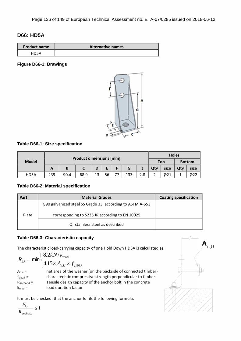
Page 136 of 149 of European Technical Assessment no. ETA-07/0285 issued on 2018-06-12
D66: HD5A
Product name Alternative names
HD5A
Figure D66-1: Drawings
Table D66-1: Size specification
Model Product dimensions [mm]
Holes
Top Bottom
A B C D E F G t Qty size Qty size
HD5A 239 90.4 68.9 13 56 77 133 2.8 2 Ø21 1 Ø22
Table D66-2: Material specification
Part Material Grades Coating specification
Plate
G90 galvanized steel SS Grade 33 according to ASTM A-653
corresponding to S235 JR according to EN 10025
Or stainless steel as described
Table D66-3: Characteristic capacity The characteristic load-carrying capacity of one Hold Down HD5A is calculated as:
kcUn
kfA
kkNR
,90,,
mod
,115,4
/2,8min
An.u = net area of the washer (on the backside of connected timber)
fc.90.k = characteristic compressive strength perpendicular to timber Ranchor.d = Tensile design capacity of the anchor bolt in the concrete kmod = load duration factor It must be checked. that the anchor fulfils the following formula:
1,
,1
danchor
d
R
F
n,U
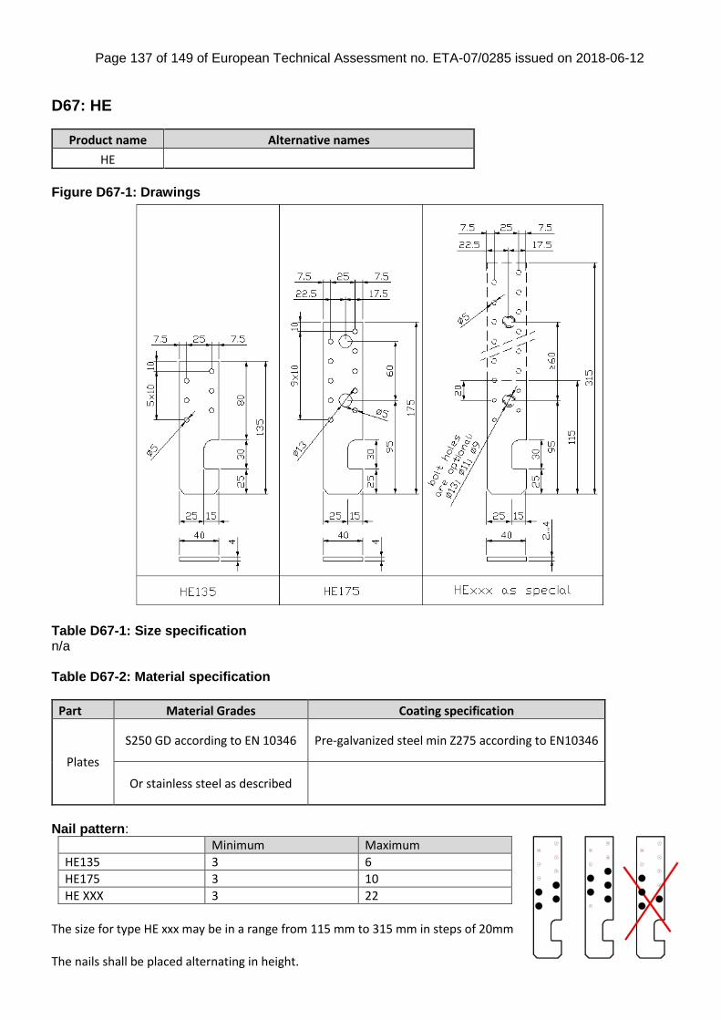
Page 137 of 149 of European Technical Assessment no. ETA-07/0285 issued on 2018-06-12
D67: HE
Product name Alternative names
HE
Figure D67-1: Drawings
Table D67-1: Size specification n/a Table D67-2: Material specification
Part Material Grades Coating specification
Plates
S250 GD according to EN 10346 Pre-galvanized steel min Z275 according to EN10346
Or stainless steel as described
Nail pattern:
Minimum Maximum
HE135 3 6
HE175 3 10
HE XXX 3 22
The size for type HE xxx may be in a range from 115 mm to 315 mm in steps of 20mm The nails shall be placed alternating in height.
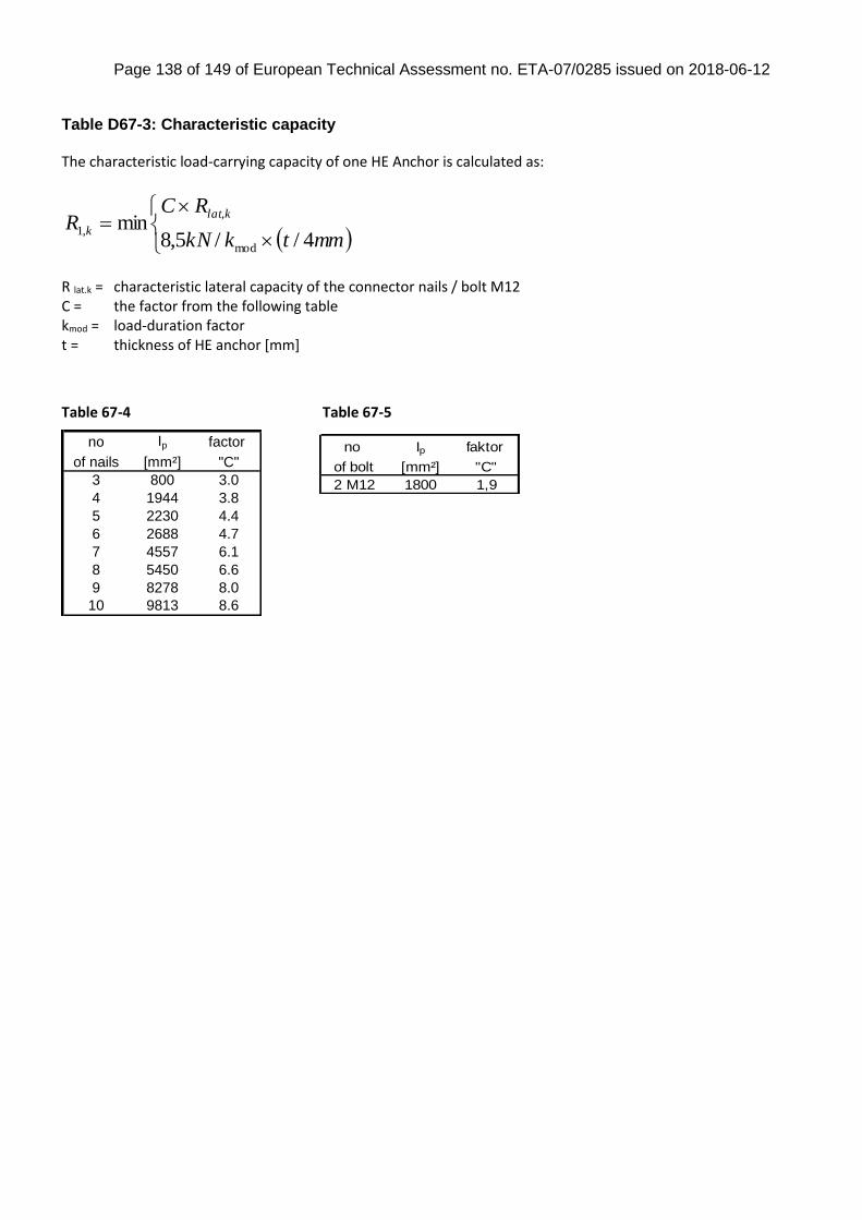
Page 138 of 149 of European Technical Assessment no. ETA-07/0285 issued on 2018-06-12
no Ip faktor
of bolt [mm²] "C"
2 M12 1800 1,9
Table D67-3: Characteristic capacity The characteristic load-carrying capacity of one HE Anchor is calculated as:
mmtkkN
RCR
klat
k4//5,8
minmod
,
,1
R lat.k = characteristic lateral capacity of the connector nails / bolt M12 C = the factor from the following table kmod = load-duration factor t = thickness of HE anchor [mm]
Table 67-4 Table 67-5
no Ip factor
of nails [mm²] "C"
3 800 3.0
4 1944 3.8
5 2230 4.4
6 2688 4.7
7 4557 6.1
8 5450 6.6
9 8278 8.0
10 9813 8.6

Page 139 of 149 of European Technical Assessment no. ETA-07/0285 issued on 2018-06-12
D68: HTT & LTT
Figure D68-1: Drawings
LTT HTT
Table D68-1: Size specification
Model Product dimensions [mm]
Holes
Top Bottom
A B C D E t Qty size Qty size Qty size Qty size
LTT20B 502 70 51 7 35 2.7 10 Ø5 2 Ø14 1 Ø21
HTT4 309 62 64 12 33 2.8 18 Ø4.7 1 Ø17.5
HTT5 403 62 64 12 33 2.8 26 Ø4.7 1 Ø17.5
HTT16 403 62 64 12 33 2.8 18 Ø4.7 1 Ø18
HTT22 569 62 64 12 33 2.8 32 Ø4.7 1 Ø18
HTT22E & HTT22F 558 60 63 12 33 3 31 Ø5 3 Ø21 3 Ø5x12 1 Ø18
HTT31 785 60 90 12 33 3 41 Ø5 6 Ø21 4 Ø5x12 1 Ø25
Table D68-2: Material specification
Part Material Grades Coating specification
HTT4 HTT5
HTT16 HTT22 & LTT20B
G90 galvanized steel SS Grade 33 according to ASTM A-653
Or stainless steel as described
HTT22F S250GD according to EN 10346 Z275 according to EN 10346
Or stainless steel as described
HTT22E S350GD according to EN 10346 Z275 according to EN 10346
Or stainless steel as described
HTT31 S350GD according to EN 10346 Z275 according to EN 10346

Page 140 of 149 of European Technical Assessment no. ETA-07/0285 issued on 2018-06-12
mod
,
,
,1
0,43
2,25
)5,3(
min
k
R
Rn
R kax
klat
k
kax
klat
kR
RnR
,
,
,13,32
)5,3(min
The nails in the vertical flap have to be arranged equally left and right about the centre-line.
Model Minimum Maximum
LTT20B 2 10
HTT4 4 18
HTT5 4 26
HTT16 4 18
HTT22 4 32
HTT22E & HTT22F
10 34
HTT31 45 CSA5,0x80 / 6 ZYK + 4 CSA5,0x80
Table D68-3: Characteristic capacity HTT4/5/16/22 The characteristic load-carrying capacity of one Hold Down is calculated as: HTT4 & HTT5 & HTT16 & HTT22 without Washer: HTT4 & HTT5 with Washer: HTT5 installed on 1,2 mm Light Gauge Steel with FPHSD34S1214R Light Gauge Steel Framing Screws (fully Screwed = 26 pcs.) with Washer: R1,k = 43,7 kN Rlat,k = characteristic lateral load-carrying capacity of one nail Rax,k = characteristic withdrawal capacity of one nail kmod = load duration factor
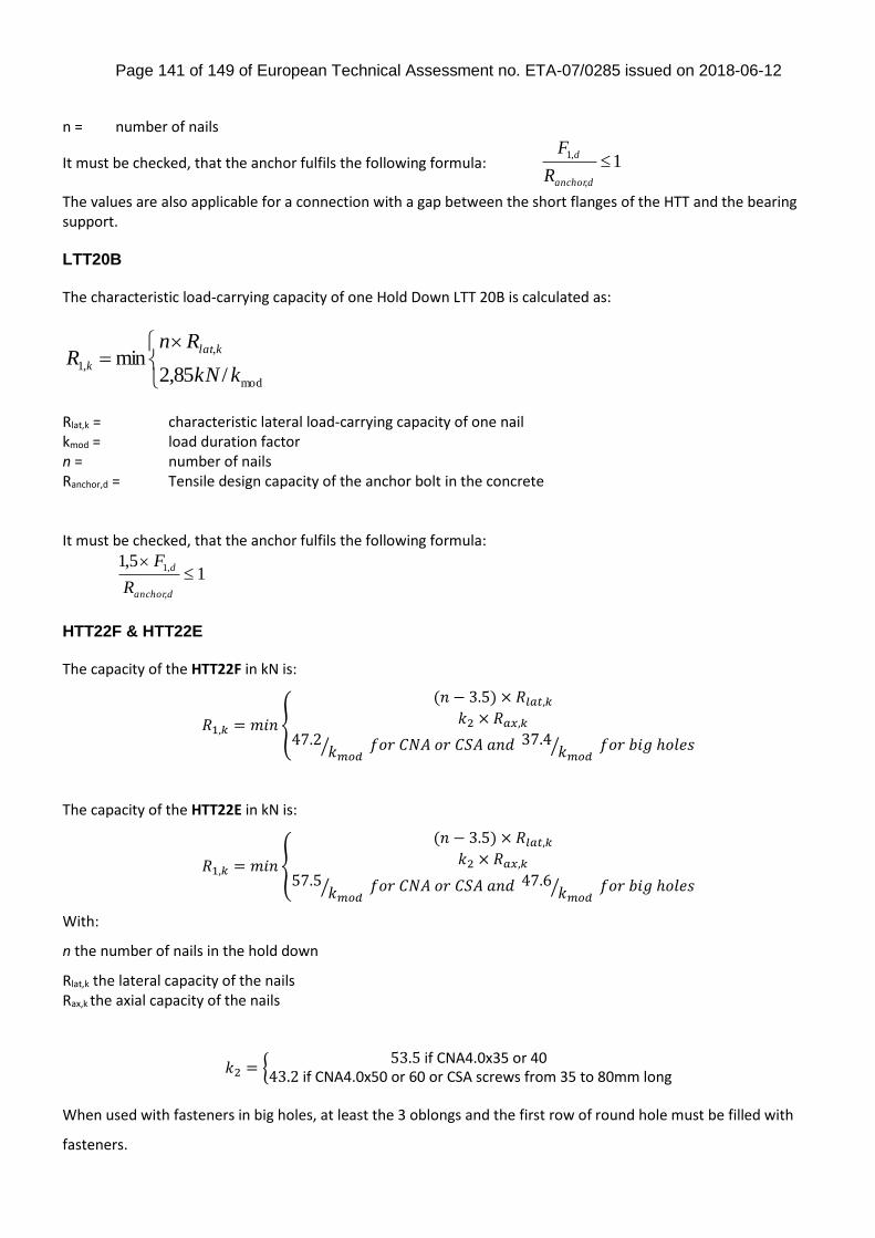
Page 141 of 149 of European Technical Assessment no. ETA-07/0285 issued on 2018-06-12
n = number of nails
It must be checked, that the anchor fulfils the following formula: 1,
,1
danchor
d
R
F
The values are also applicable for a connection with a gap between the short flanges of the HTT and the bearing support. LTT20B The characteristic load-carrying capacity of one Hold Down LTT 20B is calculated as:
mod
,
,1/85,2
minkkN
RnR
klat
k
Rlat,k = characteristic lateral load-carrying capacity of one nail kmod = load duration factor n = number of nails Ranchor,d = Tensile design capacity of the anchor bolt in the concrete It must be checked, that the anchor fulfils the following formula:
15,1
,
,1
danchor
d
R
F
HTT22F & HTT22E The capacity of the HTT22F in kN is:
𝑅1,𝑘 = 𝑚𝑖𝑛{
(𝑛 − 3.5) × 𝑅𝑙𝑎𝑡,𝑘𝑘2 × 𝑅𝑎𝑥,𝑘
47.2𝑘𝑚𝑜𝑑⁄ 𝑓𝑜𝑟 𝐶𝑁𝐴 𝑜𝑟 𝐶𝑆𝐴 𝑎𝑛𝑑 37.4 𝑘𝑚𝑜𝑑
⁄ 𝑓𝑜𝑟 𝑏𝑖𝑔 ℎ𝑜𝑙𝑒𝑠
The capacity of the HTT22E in kN is:
𝑅1,𝑘 = 𝑚𝑖𝑛{
(𝑛 − 3.5) × 𝑅𝑙𝑎𝑡,𝑘𝑘2 × 𝑅𝑎𝑥,𝑘
57.5𝑘𝑚𝑜𝑑⁄ 𝑓𝑜𝑟 𝐶𝑁𝐴 𝑜𝑟 𝐶𝑆𝐴 𝑎𝑛𝑑 47.6 𝑘𝑚𝑜𝑑
⁄ 𝑓𝑜𝑟 𝑏𝑖𝑔 ℎ𝑜𝑙𝑒𝑠
With:
n the number of nails in the hold down
Rlat,k the lateral capacity of the nails Rax,k the axial capacity of the nails
𝑘2 = {53.5 if CNA4.0x35 or 40
43.2 if CNA4.0x50 or 60 or CSA screws from 35 to 80mm long
When used with fasteners in big holes, at least the 3 oblongs and the first row of round hole must be filled with
fasteners.
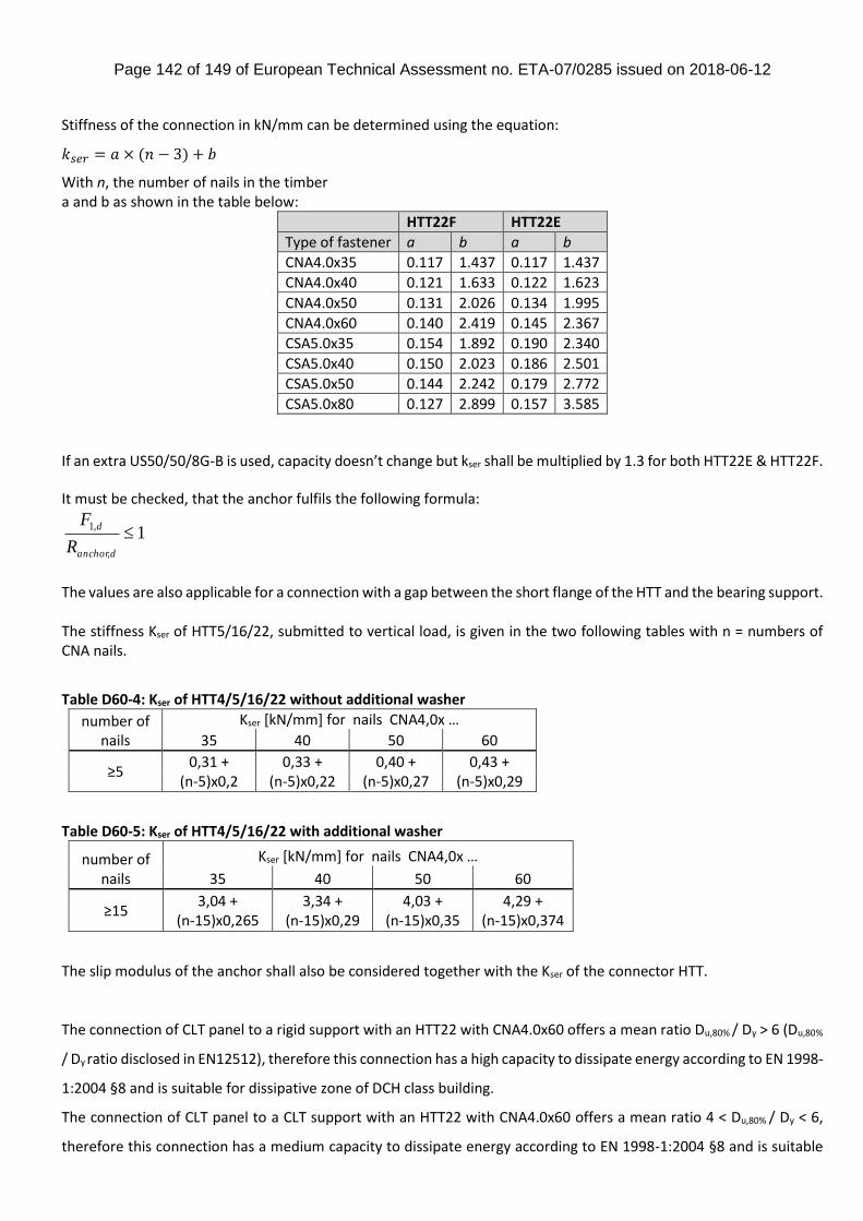
Page 142 of 149 of European Technical Assessment no. ETA-07/0285 issued on 2018-06-12
Stiffness of the connection in kN/mm can be determined using the equation:
𝑘𝑠𝑒𝑟 = 𝑎 × (𝑛 − 3) + 𝑏
With n, the number of nails in the timber a and b as shown in the table below:
HTT22F HTT22E
Type of fastener a b a b
CNA4.0x35 0.117 1.437 0.117 1.437
CNA4.0x40 0.121 1.633 0.122 1.623
CNA4.0x50 0.131 2.026 0.134 1.995
CNA4.0x60 0.140 2.419 0.145 2.367
CSA5.0x35 0.154 1.892 0.190 2.340
CSA5.0x40 0.150 2.023 0.186 2.501
CSA5.0x50 0.144 2.242 0.179 2.772
CSA5.0x80 0.127 2.899 0.157 3.585 If an extra US50/50/8G-B is used, capacity doesn’t change but kser shall be multiplied by 1.3 for both HTT22E & HTT22F. It must be checked, that the anchor fulfils the following formula:
1,
,1
danchor
d
R
F
The values are also applicable for a connection with a gap between the short flange of the HTT and the bearing support. The stiffness Kser of HTT5/16/22, submitted to vertical load, is given in the two following tables with n = numbers of CNA nails.
Table D60-4: Kser of HTT4/5/16/22 without additional washer
number of nails
Kser [kN/mm] for nails CNA4,0x …
35 40 50 60
≥5 0,31 +
(n-5)x0,2 0,33 +
(n-5)x0,22 0,40 +
(n-5)x0,27 0,43 +
(n-5)x0,29
Table D60-5: Kser of HTT4/5/16/22 with additional washer
number of nails
Kser [kN/mm] for nails CNA4,0x …
35 40 50 60
≥15 3,04 +
(n-15)x0,265 3,34 +
(n-15)x0,29 4,03 +
(n-15)x0,35 4,29 +
(n-15)x0,374
The slip modulus of the anchor shall also be considered together with the Kser of the connector HTT.
The connection of CLT panel to a rigid support with an HTT22 with CNA4.0x60 offers a mean ratio Du,80% / Dy > 6 (Du,80%
/ Dy ratio disclosed in EN12512), therefore this connection has a high capacity to dissipate energy according to EN 1998-
1:2004 §8 and is suitable for dissipative zone of DCH class building.
The connection of CLT panel to a CLT support with an HTT22 with CNA4.0x60 offers a mean ratio 4 < Du,80% / Dy < 6,
therefore this connection has a medium capacity to dissipate energy according to EN 1998-1:2004 §8 and is suitable
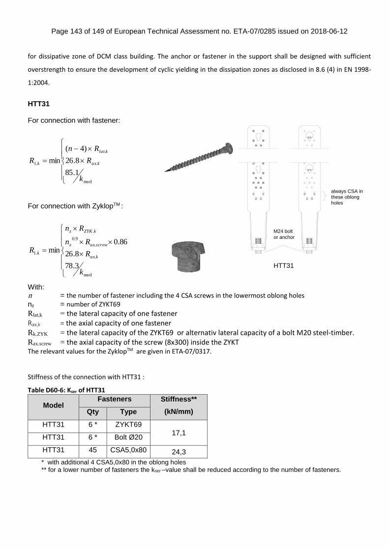
Page 143 of 149 of European Technical Assessment no. ETA-07/0285 issued on 2018-06-12
for dissipative zone of DCM class building. The anchor or fastener in the support shall be designed with sufficient
overstrength to ensure the development of cyclic yielding in the dissipation zones as disclosed in 8.6 (4) in EN 1998-
1:2004.
HTT31 For connection with fastener:
mod
.
.
.1
1.85
8.26
)4(
min
k
R
Rn
R kax
klat
k
For connection with ZyklopTM :
mod
.
.
9.0
.
.1
3.78
8.26
86.0min
k
R
Rn
Rn
Rkax
screwaxz
kZYKz
k
With: n = the number of fastener including the 4 CSA screws in the lowermost oblong holes
nz = number of ZYKT69
Rlat,k = the lateral capacity of one fastener Rax,k = the axial capacity of one fastener Rk.ZYK = the lateral capacity of the ZYKT69 or alternativ lateral capacity of a bolt M20 steel-timber. Rax.screw = the axial capacity of the screw (8x300) inside the ZYKT The relevant values for the ZyklopTM are given in ETA-07/0317.
Stiffness of the connection with HTT31 :
Table D60-6: Kser of HTT31
Model Fasteners Stiffness**
(kN/mm) Qty Type
HTT31 6 * ZYKT69 17,1
HTT31 6 * Bolt Ø20
HTT31 45 CSA5,0x80 24,3
* with additional 4 CSA5,0x80 in the oblong holes ** for a lower number of fasteners the kser –value shall be reduced according to the number of fasteners.
always CSA in these oblong
holes
M24 bolt
or anchor
HTT31
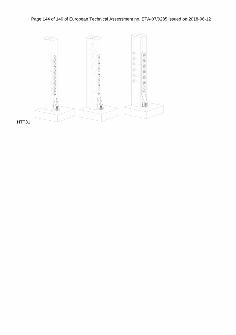
Page 144 of 149 of European Technical Assessment no. ETA-07/0285 issued on 2018-06-12
HTT31
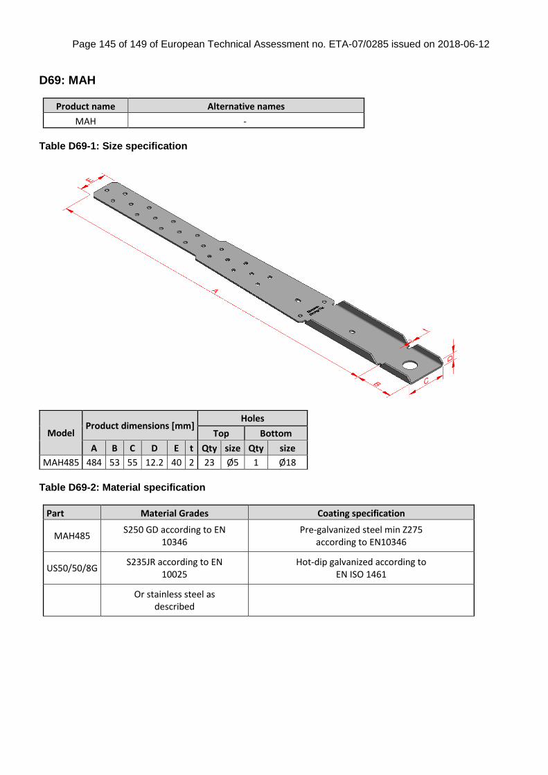
Page 145 of 149 of European Technical Assessment no. ETA-07/0285 issued on 2018-06-12
D69: MAH
Product name Alternative names
MAH -
Table D69-1: Size specification
Model Product dimensions [mm]
Holes
Top Bottom
A B C D E t Qty size Qty size
MAH485 484 53 55 12.2 40 2 23 Ø5 1 Ø18
Table D69-2: Material specification
Part Material Grades Coating specification
MAH485 S250 GD according to EN
10346 Pre-galvanized steel min Z275
according to EN10346
US50/50/8G S235JR according to EN
10025 Hot-dip galvanized according to
EN ISO 1461
Or stainless steel as
described
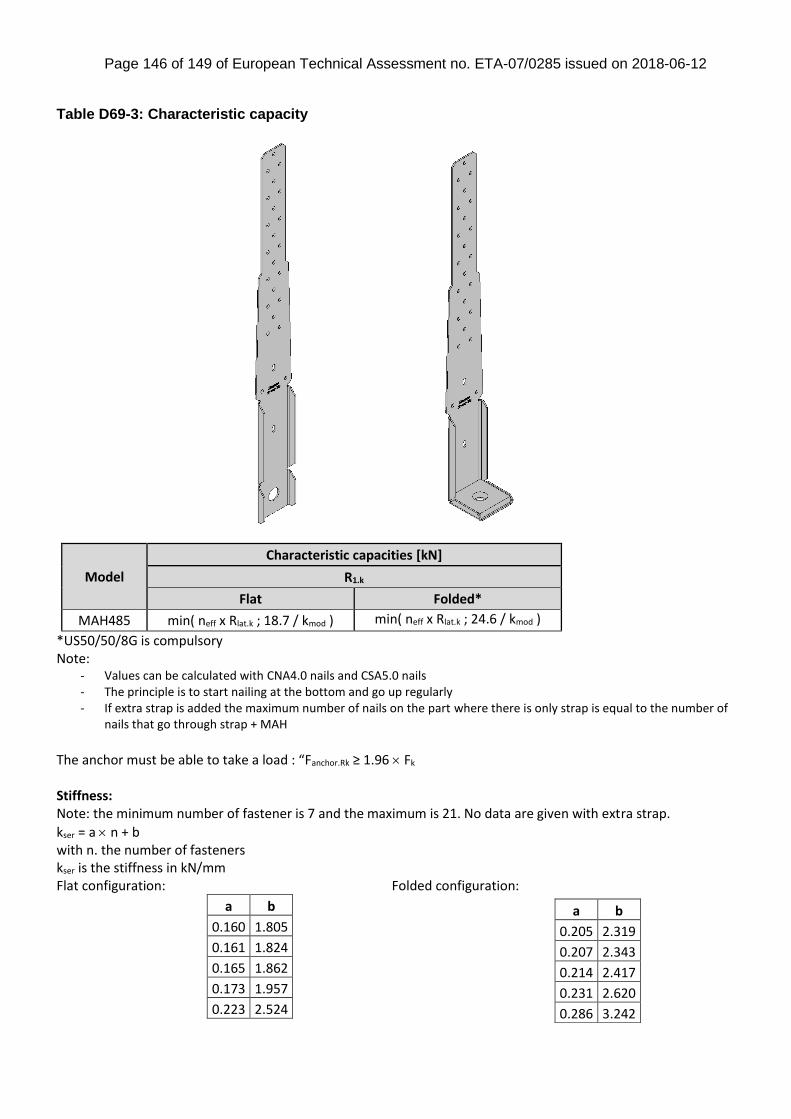
Page 146 of 149 of European Technical Assessment no. ETA-07/0285 issued on 2018-06-12
Table D69-3: Characteristic capacity
Model
Characteristic capacities [kN]
R1.k
Flat Folded*
MAH485 min( neff x Rlat.k ; 18.7 / kmod ) min( neff x Rlat.k ; 24.6 / kmod )
*US50/50/8G is compulsory Note:
- Values can be calculated with CNA4.0 nails and CSA5.0 nails - The principle is to start nailing at the bottom and go up regularly - If extra strap is added the maximum number of nails on the part where there is only strap is equal to the number of
nails that go through strap + MAH
The anchor must be able to take a load : “Fanchor.Rk ≥ 1.96 Fk Stiffness: Note: the minimum number of fastener is 7 and the maximum is 21. No data are given with extra strap.
kser = a n + b with n. the number of fasteners kser is the stiffness in kN/mm Flat configuration: Folded configuration:
a b
0.160 1.805
0.161 1.824
0.165 1.862
0.173 1.957
0.223 2.524
a b
0.205 2.319
0.207 2.343
0.214 2.417
0.231 2.620
0.286 3.242
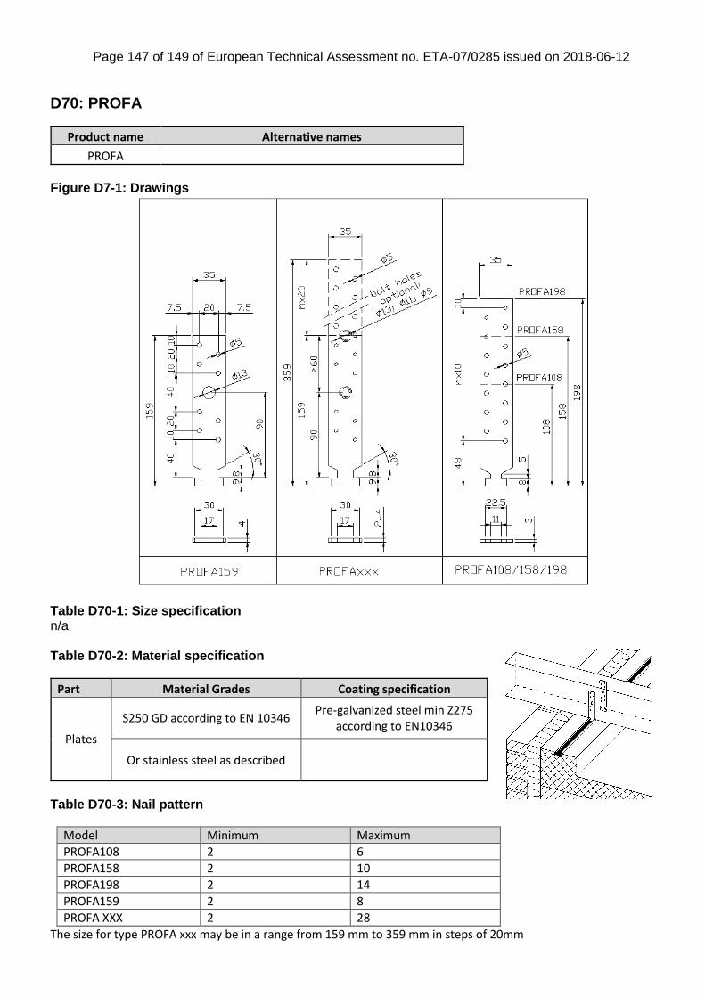
Page 147 of 149 of European Technical Assessment no. ETA-07/0285 issued on 2018-06-12
D70: PROFA
Product name Alternative names
PROFA
Figure D7-1: Drawings
Table D70-1: Size specification n/a Table D70-2: Material specification
Part Material Grades Coating specification
Plates
S250 GD according to EN 10346 Pre-galvanized steel min Z275
according to EN10346
Or stainless steel as described
Table D70-3: Nail pattern
Model Minimum Maximum
PROFA108 2 6
PROFA158 2 10
PROFA198 2 14
PROFA159 2 8
PROFA XXX 2 28
The size for type PROFA xxx may be in a range from 159 mm to 359 mm in steps of 20mm
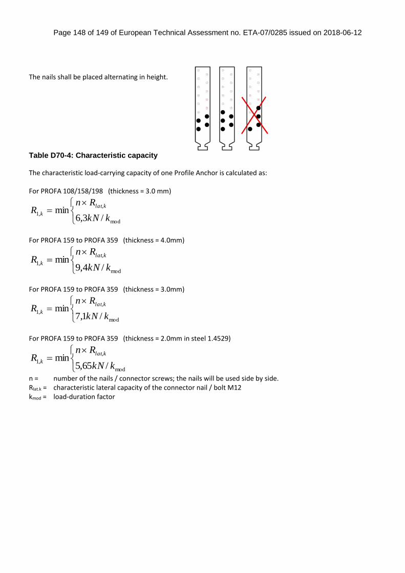
Page 148 of 149 of European Technical Assessment no. ETA-07/0285 issued on 2018-06-12
The nails shall be placed alternating in height. Table D70-4: Characteristic capacity The characteristic load-carrying capacity of one Profile Anchor is calculated as: For PROFA 108/158/198 (thickness = 3.0 mm)
mod
,
,1/3,6
minkkN
RnR
klat
k
For PROFA 159 to PROFA 359 (thickness = 4.0mm)
mod
,
,1/4,9
minkkN
RnR
klat
k
For PROFA 159 to PROFA 359 (thickness = 3.0mm)
mod
,
,1/1,7
minkkN
RnR
klat
k
For PROFA 159 to PROFA 359 (thickness = 2.0mm in steel 1.4529)
mod
,
,1/65,5
minkkN
RnR
klat
k
n = number of the nails / connector screws; the nails will be used side by side. Rlat.k = characteristic lateral capacity of the connector nail / bolt M12 kmod = load-duration factor
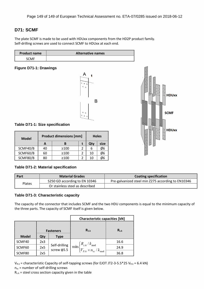
Page 149 of 149 of European Technical Assessment no. ETA-07/0285 issued on 2018-06-12
D71: SCMF
The plate SCMF is made to be used with HDUxx components from the HD2P product family. Self-drilling screws are used to connect SCMF to HDUxx at each end.
Product name Alternative names
SCMF
Figure D71-1: Drawings
Table D71-1: Size specification
Model Product dimensions [mm] Holes
A B t Qty size
SCMF40/B 40 ≥100 2 6 Ø6
SCMF60/B 60 ≥100 2 10 Ø6
SCMF80/B 80 ≥100 2 10 Ø6
Table D71-2: Material specification
Part Material Grades Coating specification
Plates S250 GD according to EN 10346 Pre-galvanized steel min Z275 according to EN10346
Or stainless steel as described
Table D71-3: Characteristic capacity The capacity of the connector that includes SCMF and the two HDU components is equal to the minimum capacity of the three parts. The capacity of SCMF itself is given below.
Characteristic capacities [kN]
Model
Fasteners R1.k Rs.k
Qty Type
SCMF40 2x3 Self-drilling screw φ5.5
16.6
SCMF60 2x5 24.9
SCMF80 2x5 36.8
VR.k = characteristic Capacity of self-tapping screws (for EJOT JT2-3-5.5*25 VR.k = 6.4 kN) nsc = number of self-drilling screws Rs.k = steel cross section capacity given in the table