Embed Size (px)
Citation preview
Created Last saved Printed Revision Document No. Prepared by Approved by 2010-02-18 2010-07-02 2011-02-22 1 2086930 Stian Abelsen Arild Sagebø
EV Powercharger CAN protocol
C:\Jobb\RND1499 EV Charger\Documenter\EV Powercharger CAN protocol description (B-2086930-1-1).doc 1 / 24
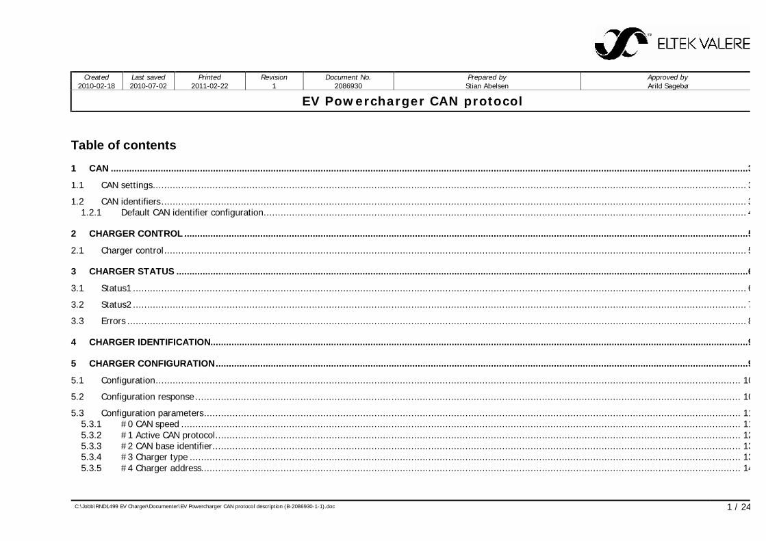
Table of contents 1 CAN ................................................................................................................................................................................................................................................... 3
1.1 CAN settings ................................................................................................................................................................................................................. 3
1.2 CAN identifiers .............................................................................................................................................................................................................. 31.2.1 Default CAN identifier configuration .......................................................................................................................................................................... 4
2 CHARGER CONTROL ....................................................................................................................................................................................................................... 5
2.1 Charger control ............................................................................................................................................................................................................. 5
3 CHARGER STATUS .......................................................................................................................................................................................................................... 6
3.1 Status1 ........................................................................................................................................................................................................................ 6
3.2 Status2 ........................................................................................................................................................................................................................ 7
3.3 Errors .......................................................................................................................................................................................................................... 8
4 CHARGER IDENTIFICATION............................................................................................................................................................................................................. 9
5 CHARGER CONFIGURATION ........................................................................................................................................................................................................... 9
5.1 Configuration .............................................................................................................................................................................................................. 10
5.2 Configuration response ................................................................................................................................................................................................ 10
5.3 Configuration parameters ............................................................................................................................................................................................. 115.3.1 #0 CAN speed ..................................................................................................................................................................................................... 115.3.2 #1 Active CAN protocol ......................................................................................................................................................................................... 125.3.3 #2 CAN base identifier .......................................................................................................................................................................................... 135.3.4 #3 Charger type .................................................................................................................................................................................................. 135.3.5 #4 Charger address.............................................................................................................................................................................................. 14
EV Powercharger CAN protocol
C:\Jobb\RND1499 EV Charger\Documenter\EV Powercharger CAN protocol description (B-2086930-1-1).doc 2 / 24
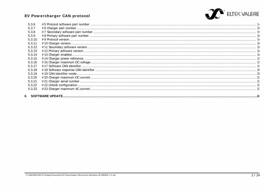
5.3.6 #5 Protocol software part number ......................................................................................................................................................................... 145.3.7 #6 Charger part number ....................................................................................................................................................................................... 155.3.8 #7 Secondary software part number ...................................................................................................................................................................... 155.3.9 #8 Primary software part number .......................................................................................................................................................................... 165.3.10 #9 Protocol version .............................................................................................................................................................................................. 165.3.11 #10 Charger version............................................................................................................................................................................................. 165.3.12 #11 Secondary software version ............................................................................................................................................................................ 185.3.13 #12 Primary software version ................................................................................................................................................................................ 185.3.14 #13 Charger enabled ............................................................................................................................................................................................ 185.3.15 #14 Charger power reference ................................................................................................................................................................................ 195.3.16 #15 Charger maximum DC voltage ........................................................................................................................................................................ 195.3.17 #17 Software CAN identifier .................................................................................................................................................................................. 195.3.18 #18 Software response CAN identifier .................................................................................................................................................................... 205.3.19 #19 CAN identifier mode ....................................................................................................................................................................................... 205.3.20 #20 Charger maximum DC current ......................................................................................................................................................................... 225.3.21 #21 Charger serial number ................................................................................................................................................................................... 225.3.22 #22 Unlock configuration ...................................................................................................................................................................................... 225.3.23 #23 Charger maximum AC current ......................................................................................................................................................................... 23
6 SOFTWARE UPDATE ...................................................................................................................................................................................................................... 24
EV Powercharger CAN protocol
C:\Jobb\RND1499 EV Charger\Documenter\EV Powercharger CAN protocol description (B-2086930-1-1).doc 3 / 24
1 CAN
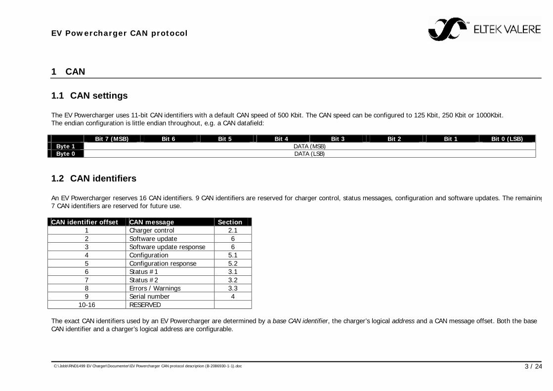
1.1 CAN settings The EV Powercharger uses 11-bit CAN identifiers with a default CAN speed of 500 Kbit. The CAN speed can be configured to 125 Kbit, 250 Kbit or 1000Kbit. The endian configuration is little endian throughout, e.g. a CAN datafield: Bit 7 (MSB) Bit 6 Bit 5 Bit 4 Bit 3 Bit 2 Bit 1 Bit 0 (LSB)
Byte 1 DATA (MSB) Byte 0 DATA (LSB)
1.2 CAN identifiers An EV Powercharger reserves 16 CAN identifiers. 9 CAN identifiers are reserved for charger control, status messages, configuration and software updates. The remaining 7 CAN identifiers are reserved for future use. CAN identifier offset CAN message Section
1 Charger control 2.1 2 Software update 6 3 Software update response 6 4 Configuration 5.1 5 Configuration response 5.2 6 Status #1 3.1 7 Status #2 3.2 8 Errors / Warnings 3.3 9 Serial number 4
10-16 RESERVED The exact CAN identifiers used by an EV Powercharger are determined by a base CAN identifier, the charger’s logical address and a CAN message offset. Both the base CAN identifier and a charger’s logical address are configurable.

EV Powercharger CAN protocol
C:\Jobb\RND1499 EV Charger\Documenter\EV Powercharger CAN protocol description (B-2086930-1-1).doc 4 / 24
The CAN identifier for a specific CAN message, base CAN identifier and charger address configuration is: Message CAN identifier = CAN identifier offset + base CAN identifier + (charger address – 1) * 16
1.2.1 Default CAN identifier configuration The default CAN identifier setup for an EV Powercharger uses: Base CAN identifier: 0x2FF Charger address: 1 CAN message Charger address = 1 Charger address = 2 Charger address = 15 Charger address = 16 Charger control (broadcast) 0x2FF 0x2FF 0x2FF 0x2FF Individual charger control 0x300 0x310 0x3E0 0x3F0 Software update 0x301 0x311 0x3E1 0x3F1 Software update response 0x302 0x312 0x3E2 0x3F2 Configuration 0x303 0x313 0x3E3 0x3F3 Configuration response 0x304 0x314 0x3E4 0x3F4 Status #1 0x305 0x315 0x3E5 0x3F5 Status #2 0x306 0x316 0x3E6 0x3F6 Errors / Warnings 0x307 0x317 0x3E7 0x3F7 Serial number 0x308 0x318 0x3E8 0x3F8 Note that the base CAN identifier is always used as a broadcast charger control message (handled by all chargers).
EV Powercharger CAN protocol
C:\Jobb\RND1499 EV Charger\Documenter\EV Powercharger CAN protocol description (B-2086930-1-1).doc 5 / 24
2 Charger control
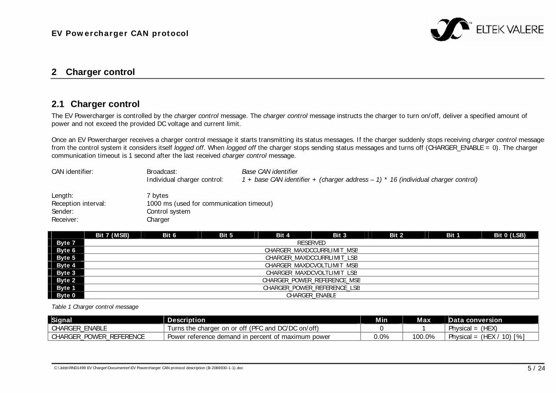
2.1 Charger control The EV Powercharger is controlled by the charger control message. The charger control message instructs the charger to turn on/off, deliver a specified amount of power and not exceed the provided DC voltage and current limit. Once an EV Powercharger receives a charger control message it starts transmitting its status messages. If the charger suddenly stops receiving charger control messages from the control system it considers itself logged off. When logged off the charger stops sending status messages and turns off (CHARGER_ENABLE = 0). The charger communication timeout is 1 second after the last received charger control message. CAN identifier: Broadcast: Base CAN identifier
Individual charger control: 1 + base CAN identifier + (charger address – 1) * 16 (individual charger control) Length: 7 bytes Reception interval: 1000 ms (used for communication timeout) Sender: Control system Receiver: Charger Bit 7 (MSB) Bit 6 Bit 5 Bit 4 Bit 3 Bit 2 Bit 1 Bit 0 (LSB)
Byte 7 RESERVED Byte 6 CHARGER_MAXDCCURRLIMIT_MSB Byte 5 CHARGER_MAXDCCURRLIMIT_LSB Byte 4 CHARGER_MAXDCVOLTLIMIT_MSB Byte 3 CHARGER_MAXDCVOLTLIMIT_LSB Byte 2 CHARGER_POWER_REFERENCE_MSB Byte 1 CHARGER_POWER_REFERENCE_LSB Byte 0 CHARGER_ENABLE
Table 1 Charger control message
Signal Description Min Max Data conversion CHARGER_ENABLE Turns the charger on or off (PFC and DC/DC on/off) 0 1 Physical = (HEX) CHARGER_POWER_REFERENCE Power reference demand in percent of maximum power 0.0% 100.0% Physical = (HEX / 10) [%]
EV Powercharger CAN protocol
C:\Jobb\RND1499 EV Charger\Documenter\EV Powercharger CAN protocol description (B-2086930-1-1).doc 6 / 24
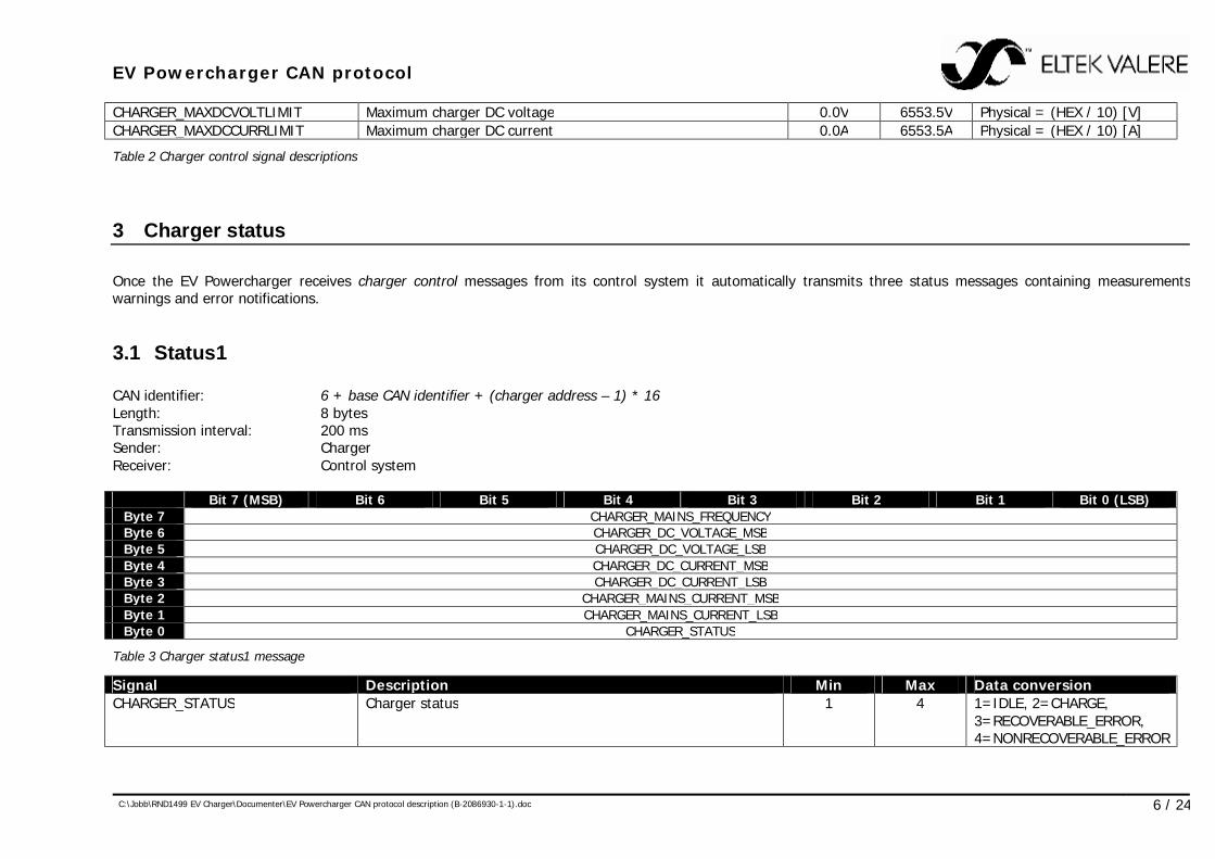
CHARGER_MAXDCVOLTLIMIT Maximum charger DC voltage 0.0V 6553.5V Physical = (HEX / 10) [V] CHARGER_MAXDCCURRLIMIT Maximum charger DC current 0.0A 6553.5A Physical = (HEX / 10) [A]
Table 2 Charger control signal descriptions
3 Charger status Once the EV Powercharger receives charger control messages from its control system it automatically transmits three status messages containing measurements, warnings and error notifications.
3.1 Status1 CAN identifier: 6 + base CAN identifier + (charger address – 1) * 16 Length: 8 bytes Transmission interval: 200 ms Sender: Charger Receiver: Control system Bit 7 (MSB) Bit 6 Bit 5 Bit 4 Bit 3 Bit 2 Bit 1 Bit 0 (LSB)
Byte 7 CHARGER_MAINS_FREQUENCY Byte 6 CHARGER_DC_VOLTAGE_MSB Byte 5 CHARGER_DC_VOLTAGE_LSB Byte 4 CHARGER_DC_CURRENT_MSB Byte 3 CHARGER_DC_CURRENT_LSB Byte 2 CHARGER_MAINS_CURRENT_MSB Byte 1 CHARGER_MAINS_CURRENT_LSB Byte 0 CHARGER_STATUS
Table 3 Charger status1 message
Signal Description Min Max Data conversion CHARGER_STATUS Charger status 1 4 1=IDLE, 2=CHARGE,
3=RECOVERABLE_ERROR, 4=NONRECOVERABLE_ERROR
EV Powercharger CAN protocol
C:\Jobb\RND1499 EV Charger\Documenter\EV Powercharger CAN protocol description (B-2086930-1-1).doc 7 / 24
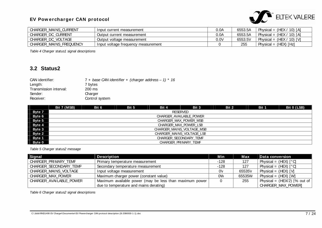
CHARGER_MAINS_CURRENT Input current measurement 0.0A 6553.5A Physical = (HEX / 10) [A] CHARGER_DC_CURRENT Output current measurement 0.0A 6553.5A Physical = (HEX / 10) [A] CHARGER_DC_VOLTAGE Output voltage measurement 0.0V 6553.5V Physical = (HEX / 10) [V] CHARGER_MAINS_FREQUENCY Input voltage frequency measurement 0 255 Physical = (HEX) [Hz]
Table 4 Charger status1 signal descriptions
3.2 Status2 CAN identifier: 7 + base CAN identifier + (charger address – 1) * 16 Length: 7 bytes Transmission interval: 200 ms Sender: Charger Receiver: Control system Bit 7 (MSB) Bit 6 Bit 5 Bit 4 Bit 3 Bit 2 Bit 1 Bit 0 (LSB)
Byte 7 RESERVED Byte 6 CHARGER_AVAILABLE_POWER Byte 5 CHARGER_MAX_POWER_MSB Byte 4 CHARGER_MAX_POWER_LSB Byte 3 CHARGER_MAINS_VOLTAGE_MSB Byte 2 CHARGER_MAINS_VOLTAGE_LSB Byte 1 CHARGER_SECONDARY_TEMP Byte 0 CHARGER_PRIMARY_TEMP
Table 5 Charger status2 message
Signal Description Min Max Data conversion CHARGER_PRIMARY_TEMP Primary temperature measurement -128 127 Physical = (HEX) [°C] CHARGER_SECONDARY_TEMP Secondary temperature measurement -128 127 Physical = (HEX) [°C] CHARGER_MAINS_VOLTAGE Input voltage measurement 0V 65535V Physical = (HEX) [V] CHARGER_MAX_POWER Maximum charger power (constant value) 0W 65535W Physical = (HEX) [W] CHARGER_AVAILABLE_POWER Maximum available power (may be less than maximum power
due to temperature and mains derating) 0 255 Physical = (HEX/2) [% out of
CHARGER_MAX_POWER]
Table 6 Charger status2 signal descriptions
EV Powercharger CAN protocol
C:\Jobb\RND1499 EV Charger\Documenter\EV Powercharger CAN protocol description (B-2086930-1-1).doc 8 / 24
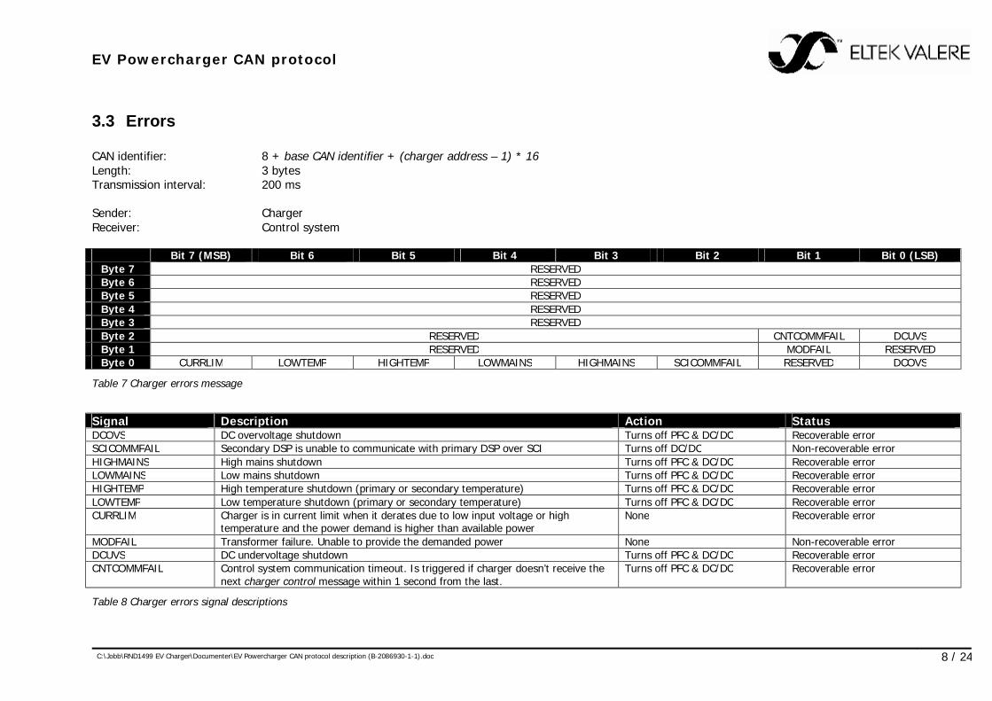
3.3 Errors CAN identifier: 8 + base CAN identifier + (charger address – 1) * 16 Length: 3 bytes Transmission interval: 200 ms Sender: Charger Receiver: Control system Bit 7 (MSB) Bit 6 Bit 5 Bit 4 Bit 3 Bit 2 Bit 1 Bit 0 (LSB)
Byte 7 RESERVED Byte 6 RESERVED Byte 5 RESERVED Byte 4 RESERVED Byte 3 RESERVED Byte 2 RESERVED CNTCOMMFAIL DCUVS Byte 1 RESERVED MODFAIL RESERVED Byte 0 CURRLIM LOWTEMP HIGHTEMP LOWMAINS HIGHMAINS SCICOMMFAIL RESERVED DCOVS
Table 7 Charger errors message
Signal Description Action Status DCOVS DC overvoltage shutdown Turns off PFC & DC/DC Recoverable error SCICOMMFAIL Secondary DSP is unable to communicate with primary DSP over SCI Turns off DC/DC Non-recoverable error HIGHMAINS High mains shutdown Turns off PFC & DC/DC Recoverable error LOWMAINS Low mains shutdown Turns off PFC & DC/DC Recoverable error HIGHTEMP High temperature shutdown (primary or secondary temperature) Turns off PFC & DC/DC Recoverable error LOWTEMP Low temperature shutdown (primary or secondary temperature) Turns off PFC & DC/DC Recoverable error CURRLIM Charger is in current limit when it derates due to low input voltage or high
temperature and the power demand is higher than available power None Recoverable error
MODFAIL Transformer failure. Unable to provide the demanded power None Non-recoverable error DCUVS DC undervoltage shutdown Turns off PFC & DC/DC Recoverable error CNTCOMMFAIL Control system communication timeout. Is triggered if charger doesn’t receive the
next charger control message within 1 second from the last. Turns off PFC & DC/DC Recoverable error
Table 8 Charger errors signal descriptions

EV Powercharger CAN protocol
C:\Jobb\RND1499 EV Charger\Documenter\EV Powercharger CAN protocol description (B-2086930-1-1).doc 9 / 24
4 Charger identification The EV Powercharger always sends a charger identification message containing its serial number and base CAN identifier. CAN identifier: 9 + base CAN identifier + (charger address – 1) * 16 Length: 8 bytes Transmission interval: 1000 ms Sender: Charger Receiver: Control system Bit 7 (MSB) Bit 6 Bit 5 Bit 4 Bit 3 Bit 2 Bit 1 Bit 0 (LSB)
Byte 7 CHARGER_BASE_CANIDENTIFIER_MSB Byte 6 CHARGER_BASE_CANIDENTIFIER_LSB Byte 5 CHARGER_SERIALNUMBER Byte 4 CHARGER_SERIALNUMBER Byte 3 CHARGER_SERIALNUMBER Byte 2 CHARGER_SERIALNUMBER Byte 1 CHARGER_SERIALNUMBER Byte 0 CHARGER_SERIALNUMBER
Table 9 Charger identification message
Signal Description Min Max Data conversion CHARGER_SERIALNUMBER Charger serial number NA NA NA CHARGER_BASE_CANIDENTIFIER Base CAN identifier (see section X) 0 1791 Physical = (HEX)
Table 10 Charger identification signal descriptions
5 Charger configuration The charger has a configuration mode and two dedicated CAN identifiers for this purpose. A configuration message is used by the control system/configuration tool to configure a charger. A configuration response is transmitted by the charger to respond with data to a read operation or to acknowledge a write operation.
EV Powercharger CAN protocol
C:\Jobb\RND1499 EV Charger\Documenter\EV Powercharger CAN protocol description (B-2086930-1-1).doc 10 / 24
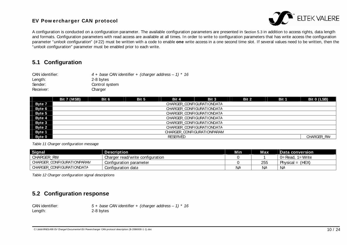
A configuration is conducted on a configuration parameter. The available configuration parameters are presented in Section 5.3 in addition to access rights, data length and formats. Configuration parameters with read access are available at all times. In order to write to configuration parameters that has write access the configuration parameter “unlock configuration” (#22) must be written with a code to enable one write access in a one second time slot. If several values need to be written, then the “unlock configuration” parameter must be enabled prior to each write.
5.1 Configuration CAN identifier: 4 + base CAN identifier + (charger address – 1) * 16 Length: 2-8 bytes Sender: Control system Receiver: Charger Bit 7 (MSB) Bit 6 Bit 5 Bit 4 Bit 3 Bit 2 Bit 1 Bit 0 (LSB)
Byte 7 CHARGER_CONFIGURATIONDATA Byte 6 CHARGER_CONFIGURATIONDATA Byte 5 CHARGER_CONFIGURATIONDATA Byte 4 CHARGER_CONFIGURATIONDATA Byte 3 CHARGER_CONFIGURATIONDATA Byte 2 CHARGER_CONFIGURATIONDATA Byte 1 CHARGER_CONFIGURATIONPARAM Byte 0 RESERVED CHARGER_RW
Table 11 Charger configuration message
Signal Description Min Max Data conversion CHARGER_RW Charger read/write configuration 0 1 0=Read, 1=Write CHARGER_CONFIGURATIONPARAM Configuration parameter 0 255 Physical = (HEX) CHARGER_CONFIGURATIONDATA Configuration data NA NA NA
Table 12 Charger configuration signal descriptions
5.2 Configuration response CAN identifier: 5 + base CAN identifier + (charger address – 1) * 16 Length: 2-8 bytes

EV Powercharger CAN protocol
C:\Jobb\RND1499 EV Charger\Documenter\EV Powercharger CAN protocol description (B-2086930-1-1).doc 11 / 24
Sender: Charger Receiver: Control system Bit 7 (MSB) Bit 6 Bit 5 Bit 4 Bit 3 Bit 2 Bit 1 Bit 0 (LSB)
Byte 7 CHARGER_CONFIGURATIONDATA Byte 6 CHARGER_CONFIGURATIONDATA Byte 5 CHARGER_CONFIGURATIONDATA Byte 4 CHARGER_CONFIGURATIONDATA Byte 3 CHARGER_CONFIGURATIONDATA Byte 2 CHARGER_CONFIGURATIONDATA Byte 1 CHARGER_CONFIGURATIONPARAM Byte 0 RESERVED CHARGER_RESPONSE CHARGER_RW
Table 13 Charger configuration response message
Signal Description Min Max Data conversion CHARGER_RW Charger read/write configuration 0 1 0=Read, 1=Write CHARGER_RESPONSE Charger configuration response 0 7 0=Ok, 1=TooHigh,
2=TooLow, 3=NotInitialized CHARGER_CONFIGURATIONPARAM Configuration parameter 0 255 Physical = (HEX) CHARGER_CONFIGURATIONDATA Configuration data NA NA NA
Table 14 Charger configuration response signal descriptions
5.3 Configuration parameters
5.3.1 #0 CAN speed Configuration parameter: 0 Access options: R/W Data length: 1 byte Description: Changes the charger’s CAN speed. The charger must be power cycled for the new change to take effect. Data conversion: CHARGER_CANSPEED 0=125Kbit, 1=250Kbit, 2=500Kbit (default), 3=1000Kbit
EV Powercharger CAN protocol
C:\Jobb\RND1499 EV Charger\Documenter\EV Powercharger CAN protocol description (B-2086930-1-1).doc 12 / 24
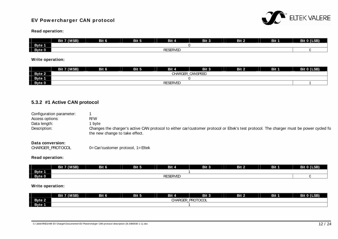
Read operation: Bit 7 (MSB) Bit 6 Bit 5 Bit 4 Bit 3 Bit 2 Bit 1 Bit 0 (LSB)
Byte 1 0 Byte 0 RESERVED 0
Write operation: Bit 7 (MSB) Bit 6 Bit 5 Bit 4 Bit 3 Bit 2 Bit 1 Bit 0 (LSB)
Byte 2 CHARGER_CANSPEED Byte 1 0 Byte 0 RESERVED 1
5.3.2 #1 Active CAN protocol Configuration parameter: 1 Access options: R/W Data length: 1 byte Description: Changes the charger’s active CAN protocol to either car/customer protocol or Eltek’s test protocol. The charger must be power cycled for
the new change to take effect. Data conversion: CHARGER_PROTOCOL 0=Car/customer protocol, 1=Eltek Read operation: Bit 7 (MSB) Bit 6 Bit 5 Bit 4 Bit 3 Bit 2 Bit 1 Bit 0 (LSB)
Byte 1 1 Byte 0 RESERVED 0
Write operation: Bit 7 (MSB) Bit 6 Bit 5 Bit 4 Bit 3 Bit 2 Bit 1 Bit 0 (LSB)
Byte 2 CHARGER_PROTOCOL Byte 1 1
EV Powercharger CAN protocol
C:\Jobb\RND1499 EV Charger\Documenter\EV Powercharger CAN protocol description (B-2086930-1-1).doc 13 / 24
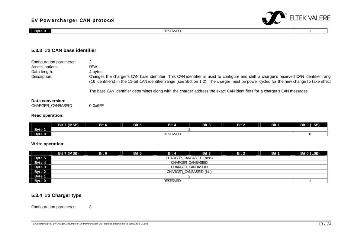
Byte 0 RESERVED 1
5.3.3 #2 CAN base identifier Configuration parameter: 2 Access options: R/W Data length: 4 bytes Description: Changes the charger’s CAN base identifier. This CAN identifier is used to configure and shift a charger’s reserved CAN identifier range
(16 identifiers) in the 11-bit CAN identifier range (see Section 1.2). The charger must be power cycled for the new change to take effect. The base CAN identifier determines along with the charger address the exact CAN identifiers for a charger’s CAN messages. Data conversion: CHARGER_CANBASEID 0-0x6FF Read operation: Bit 7 (MSB) Bit 6 Bit 5 Bit 4 Bit 3 Bit 2 Bit 1 Bit 0 (LSB)
Byte 1 2 Byte 0 RESERVED 0
Write operation: Bit 7 (MSB) Bit 6 Bit 5 Bit 4 Bit 3 Bit 2 Bit 1 Bit 0 (LSB)
Byte 5 CHARGER_CANBASEID (msb) Byte 4 CHARGER_CANBASEID Byte 3 CHARGER_CANBASEID Byte 2 CHARGER_CANBASEID (lsb) Byte 1 2 Byte 0 RESERVED 1
5.3.4 #3 Charger type Configuration parameter: 3
EV Powercharger CAN protocol
C:\Jobb\RND1499 EV Charger\Documenter\EV Powercharger CAN protocol description (B-2086930-1-1).doc 14 / 24
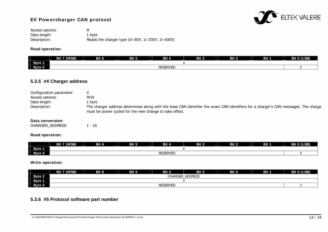
Access options: R Data length: 1 byte Description: Reads the charger type (0=80V, 1=200V, 2=400V) Read operation: Bit 7 (MSB) Bit 6 Bit 5 Bit 4 Bit 3 Bit 2 Bit 1 Bit 0 (LSB)
Byte 1 3 Byte 0 RESERVED 0
5.3.5 #4 Charger address Configuration parameter: 4 Access options: R/W Data length: 1 byte Description: The charger address determines along with the base CAN identifier the exact CAN identifiers for a charger’s CAN messages. The charger
must be power cycled for the new change to take effect. Data conversion: CHARGER_ADDRESS 1 - 16 Read operation: Bit 7 (MSB) Bit 6 Bit 5 Bit 4 Bit 3 Bit 2 Bit 1 Bit 0 (LSB)
Byte 1 4 Byte 0 RESERVED 0
Write operation: Bit 7 (MSB) Bit 6 Bit 5 Bit 4 Bit 3 Bit 2 Bit 1 Bit 0 (LSB)
Byte 2 CHARGER_ADDRESS Byte 1 4 Byte 0 RESERVED 1
5.3.6 #5 Protocol software part number

EV Powercharger CAN protocol
C:\Jobb\RND1499 EV Charger\Documenter\EV Powercharger CAN protocol description (B-2086930-1-1).doc 15 / 24
Configuration parameter: 5 Access options: R Data length: 5 bytes Description: Protocol software part number formatted as e.g. 0x4040700090 = “404070.009” Read operation: Bit 7 (MSB) Bit 6 Bit 5 Bit 4 Bit 3 Bit 2 Bit 1 Bit 0 (LSB)
Byte 1 5 Byte 0 RESERVED 0
5.3.7 #6 Charger part number Configuration parameter: 6 Access options: R Data length: 5 bytes Description: Charger part number formatted as e.g. 0x4040700090 = “404070.009” Read operation: Bit 7 (MSB) Bit 6 Bit 5 Bit 4 Bit 3 Bit 2 Bit 1 Bit 0 (LSB)
Byte 1 6 Byte 0 RESERVED 0
5.3.8 #7 Secondary software part number Configuration parameter: 7 Access options: R Data length: 5 bytes Description: Secondary software part number formatted as e.g. 0x4040700090 = “404070.009” Read operation: Bit 7 (MSB) Bit 6 Bit 5 Bit 4 Bit 3 Bit 2 Bit 1 Bit 0 (LSB)
EV Powercharger CAN protocol
C:\Jobb\RND1499 EV Charger\Documenter\EV Powercharger CAN protocol description (B-2086930-1-1).doc 16 / 24
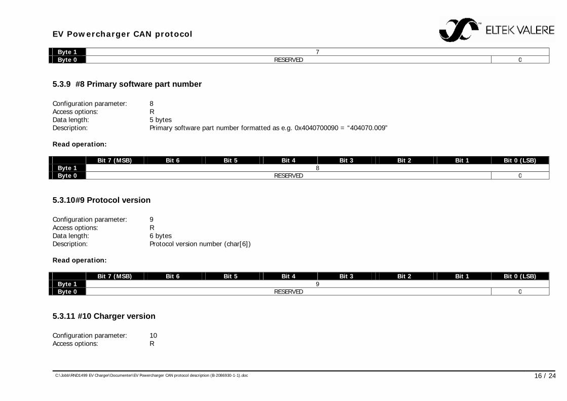
Byte 1 7 Byte 0 RESERVED 0
5.3.9 #8 Primary software part number Configuration parameter: 8 Access options: R Data length: 5 bytes Description: Primary software part number formatted as e.g. 0x4040700090 = “404070.009” Read operation: Bit 7 (MSB) Bit 6 Bit 5 Bit 4 Bit 3 Bit 2 Bit 1 Bit 0 (LSB)
Byte 1 8 Byte 0 RESERVED 0
5.3.10 #9 Protocol version Configuration parameter: 9 Access options: R Data length: 6 bytes Description: Protocol version number (char[6]) Read operation: Bit 7 (MSB) Bit 6 Bit 5 Bit 4 Bit 3 Bit 2 Bit 1 Bit 0 (LSB)
Byte 1 9 Byte 0 RESERVED 0
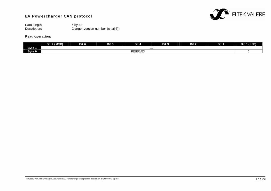
5.3.11 #10 Charger version Configuration parameter: 10 Access options: R
EV Powercharger CAN protocol
C:\Jobb\RND1499 EV Charger\Documenter\EV Powercharger CAN protocol description (B-2086930-1-1).doc 17 / 24
Data length: 6 bytes Description: Charger version number (char[6]) Read operation: Bit 7 (MSB) Bit 6 Bit 5 Bit 4 Bit 3 Bit 2 Bit 1 Bit 0 (LSB)
Byte 1 10 Byte 0 RESERVED 0
EV Powercharger CAN protocol
C:\Jobb\RND1499 EV Charger\Documenter\EV Powercharger CAN protocol description (B-2086930-1-1).doc 18 / 24
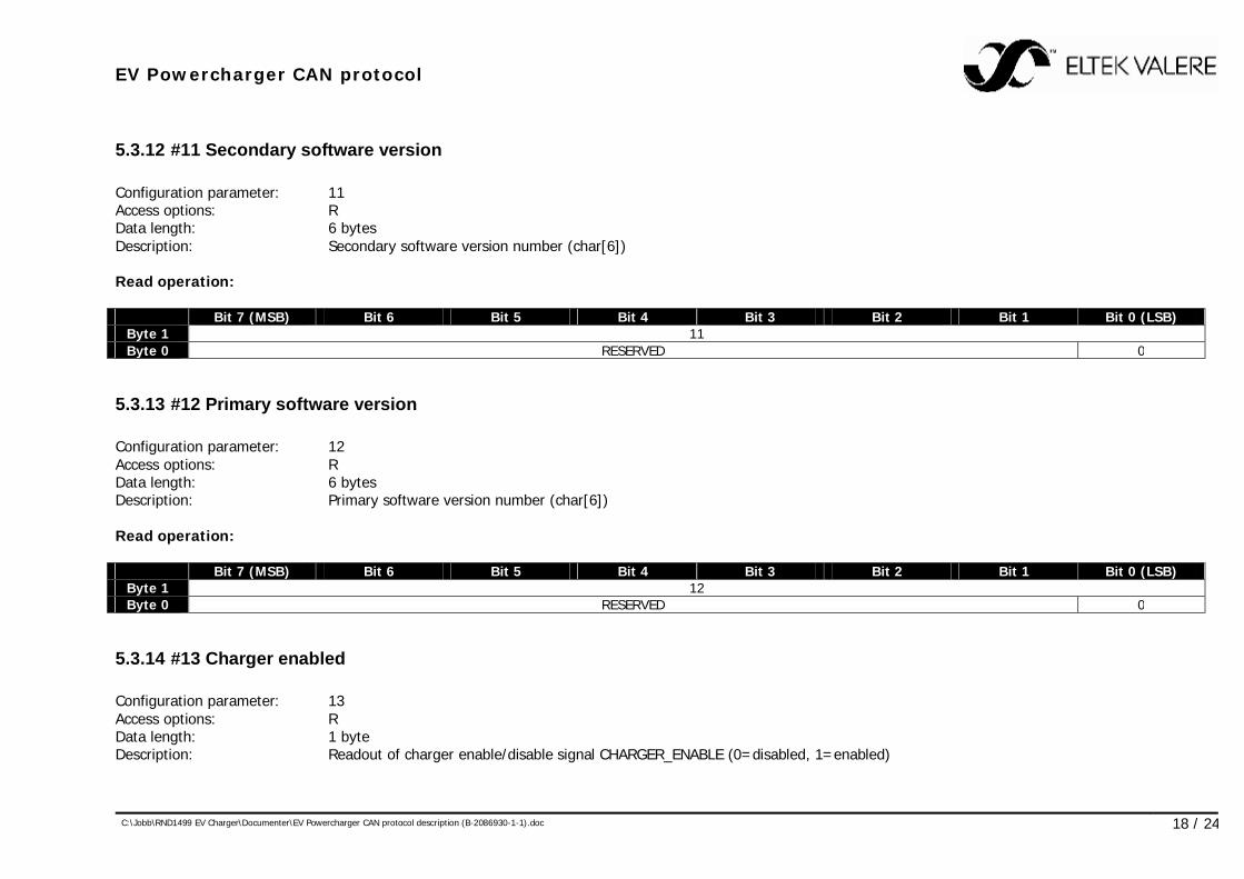
5.3.12 #11 Secondary software version Configuration parameter: 11 Access options: R Data length: 6 bytes Description: Secondary software version number (char[6]) Read operation: Bit 7 (MSB) Bit 6 Bit 5 Bit 4 Bit 3 Bit 2 Bit 1 Bit 0 (LSB)
Byte 1 11 Byte 0 RESERVED 0
5.3.13 #12 Primary software version Configuration parameter: 12 Access options: R Data length: 6 bytes Description: Primary software version number (char[6]) Read operation: Bit 7 (MSB) Bit 6 Bit 5 Bit 4 Bit 3 Bit 2 Bit 1 Bit 0 (LSB)
Byte 1 12 Byte 0 RESERVED 0
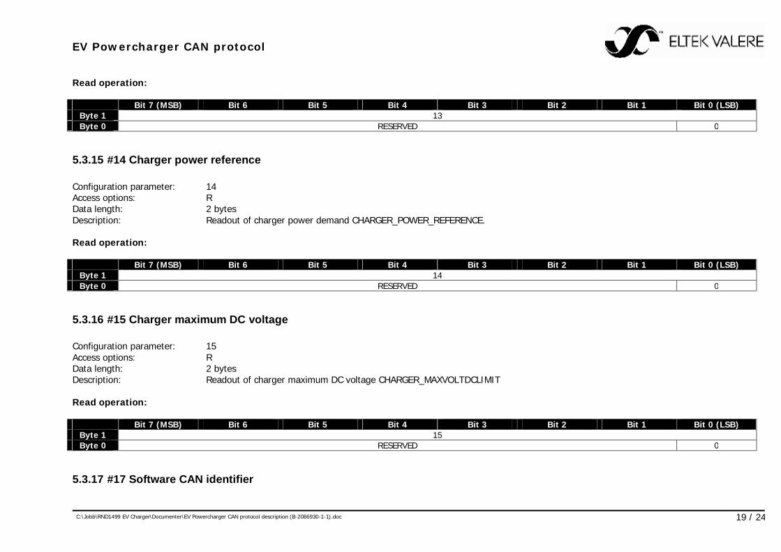
5.3.14 #13 Charger enabled Configuration parameter: 13 Access options: R Data length: 1 byte Description: Readout of charger enable/disable signal CHARGER_ENABLE (0=disabled, 1=enabled)
EV Powercharger CAN protocol
C:\Jobb\RND1499 EV Charger\Documenter\EV Powercharger CAN protocol description (B-2086930-1-1).doc 19 / 24
Read operation: Bit 7 (MSB) Bit 6 Bit 5 Bit 4 Bit 3 Bit 2 Bit 1 Bit 0 (LSB)
Byte 1 13 Byte 0 RESERVED 0
5.3.15 #14 Charger power reference Configuration parameter: 14 Access options: R Data length: 2 bytes Description: Readout of charger power demand CHARGER_POWER_REFERENCE. Read operation: Bit 7 (MSB) Bit 6 Bit 5 Bit 4 Bit 3 Bit 2 Bit 1 Bit 0 (LSB)
Byte 1 14 Byte 0 RESERVED 0
5.3.16 #15 Charger maximum DC voltage Configuration parameter: 15 Access options: R Data length: 2 bytes Description: Readout of charger maximum DC voltage CHARGER_MAXVOLTDCLIMIT Read operation: Bit 7 (MSB) Bit 6 Bit 5 Bit 4 Bit 3 Bit 2 Bit 1 Bit 0 (LSB)
Byte 1 15 Byte 0 RESERVED 0
5.3.17 #17 Software CAN identifier
EV Powercharger CAN protocol
C:\Jobb\RND1499 EV Charger\Documenter\EV Powercharger CAN protocol description (B-2086930-1-1).doc 20 / 24
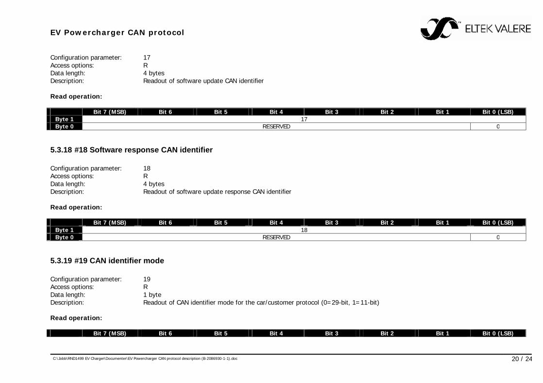
Configuration parameter: 17 Access options: R Data length: 4 bytes Description: Readout of software update CAN identifier Read operation: Bit 7 (MSB) Bit 6 Bit 5 Bit 4 Bit 3 Bit 2 Bit 1 Bit 0 (LSB)
Byte 1 17 Byte 0 RESERVED 0
5.3.18 #18 Software response CAN identifier Configuration parameter: 18 Access options: R Data length: 4 bytes Description: Readout of software update response CAN identifier Read operation: Bit 7 (MSB) Bit 6 Bit 5 Bit 4 Bit 3 Bit 2 Bit 1 Bit 0 (LSB)
Byte 1 18 Byte 0 RESERVED 0
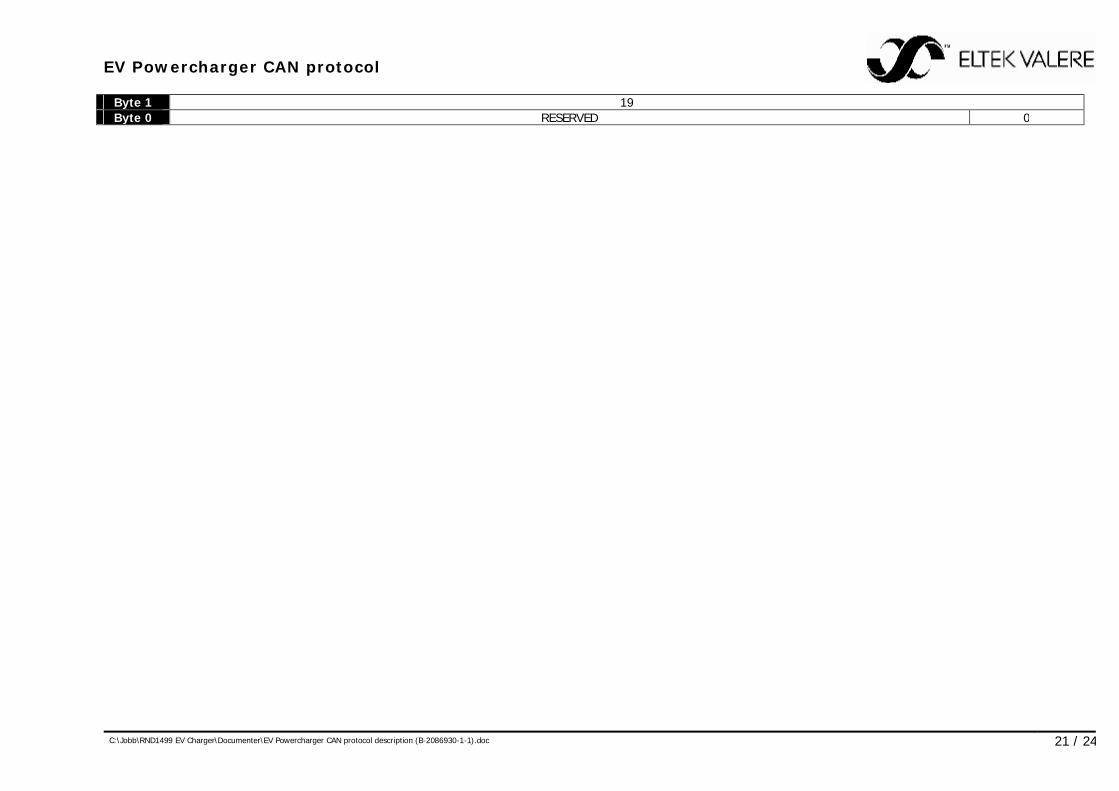
5.3.19 #19 CAN identifier mode Configuration parameter: 19 Access options: R Data length: 1 byte Description: Readout of CAN identifier mode for the car/customer protocol (0=29-bit, 1=11-bit) Read operation: Bit 7 (MSB) Bit 6 Bit 5 Bit 4 Bit 3 Bit 2 Bit 1 Bit 0 (LSB)
EV Powercharger CAN protocol
C:\Jobb\RND1499 EV Charger\Documenter\EV Powercharger CAN protocol description (B-2086930-1-1).doc 21 / 24
Byte 1 19 Byte 0 RESERVED 0
EV Powercharger CAN protocol
C:\Jobb\RND1499 EV Charger\Documenter\EV Powercharger CAN protocol description (B-2086930-1-1).doc 22 / 24
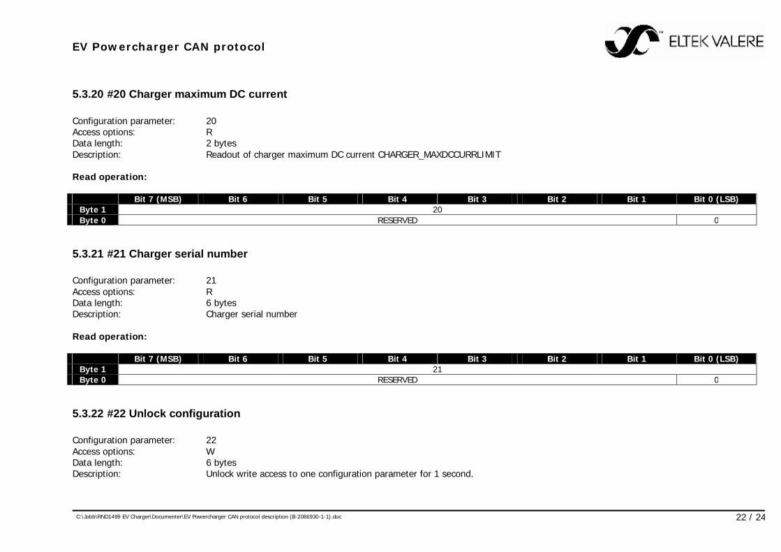
5.3.20 #20 Charger maximum DC current Configuration parameter: 20 Access options: R Data length: 2 bytes Description: Readout of charger maximum DC current CHARGER_MAXDCCURRLIMIT Read operation: Bit 7 (MSB) Bit 6 Bit 5 Bit 4 Bit 3 Bit 2 Bit 1 Bit 0 (LSB)
Byte 1 20 Byte 0 RESERVED 0
5.3.21 #21 Charger serial number Configuration parameter: 21 Access options: R Data length: 6 bytes Description: Charger serial number Read operation: Bit 7 (MSB) Bit 6 Bit 5 Bit 4 Bit 3 Bit 2 Bit 1 Bit 0 (LSB)
Byte 1 21 Byte 0 RESERVED 0
5.3.22 #22 Unlock configuration Configuration parameter: 22 Access options: W Data length: 6 bytes Description: Unlock write access to one configuration parameter for 1 second.
EV Powercharger CAN protocol
C:\Jobb\RND1499 EV Charger\Documenter\EV Powercharger CAN protocol description (B-2086930-1-1).doc 23 / 24
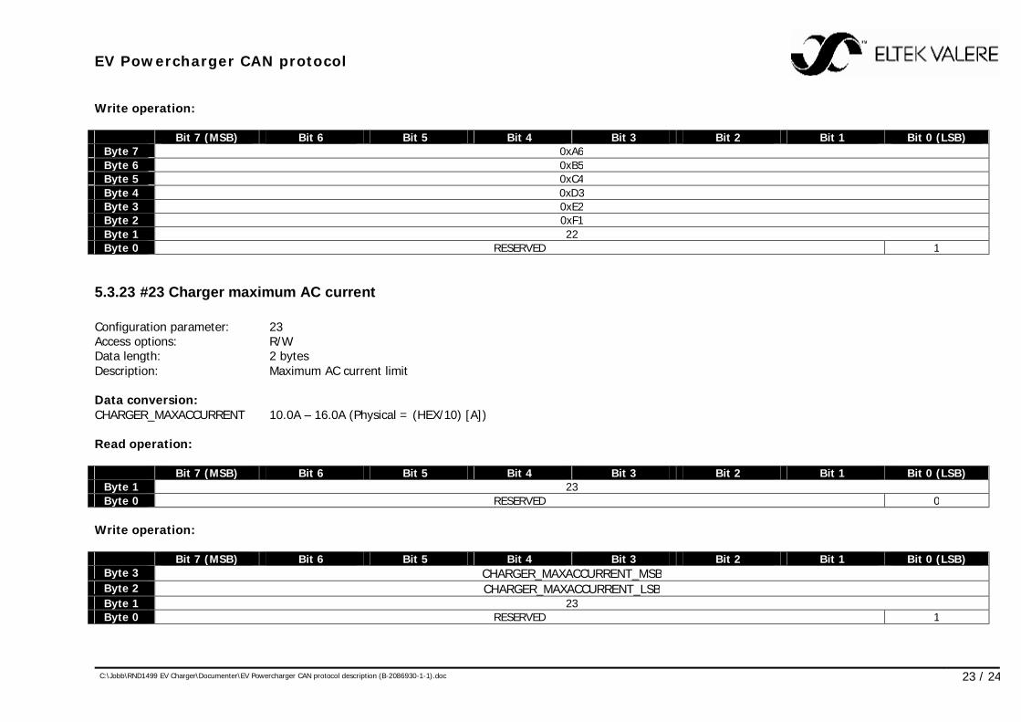
Write operation: Bit 7 (MSB) Bit 6 Bit 5 Bit 4 Bit 3 Bit 2 Bit 1 Bit 0 (LSB)
Byte 7 0xA6 Byte 6 0xB5 Byte 5 0xC4 Byte 4 0xD3 Byte 3 0xE2 Byte 2 0xF1 Byte 1 22 Byte 0 RESERVED 1
5.3.23 #23 Charger maximum AC current Configuration parameter: 23 Access options: R/W Data length: 2 bytes Description: Maximum AC current limit Data conversion: CHARGER_MAXACCURRENT 10.0A – 16.0A (Physical = (HEX/10) [A]) Read operation: Bit 7 (MSB) Bit 6 Bit 5 Bit 4 Bit 3 Bit 2 Bit 1 Bit 0 (LSB)
Byte 1 23 Byte 0 RESERVED 0
Write operation: Bit 7 (MSB) Bit 6 Bit 5 Bit 4 Bit 3 Bit 2 Bit 1 Bit 0 (LSB)
Byte 3 CHARGER_MAXACCURRENT_MSB Byte 2 CHARGER_MAXACCURRENT_LSB Byte 1 23 Byte 0 RESERVED 1
EV Powercharger CAN protocol
C:\Jobb\RND1499 EV Charger\Documenter\EV Powercharger CAN protocol description (B-2086930-1-1).doc 24 / 24
6 Software update The protocol specification for updating primary, secondary and CAN protocol software is described in the following document:
• Firmware Loader CAN Protocol (2056153-1-1) Eltek Valere has applications and equipment available to update EV Powercharger software. The EV Powercharger uses the following CAN identifiers for software update purposes: Software update: 2 + base CAN identifier + (charger address – 1) * 16 Software update response: 3 + base CAN identifier + (charger address – 1) * 16