Embed Size (px)
Citation preview
N. Mary
EVA Vehicle Interfaces
1
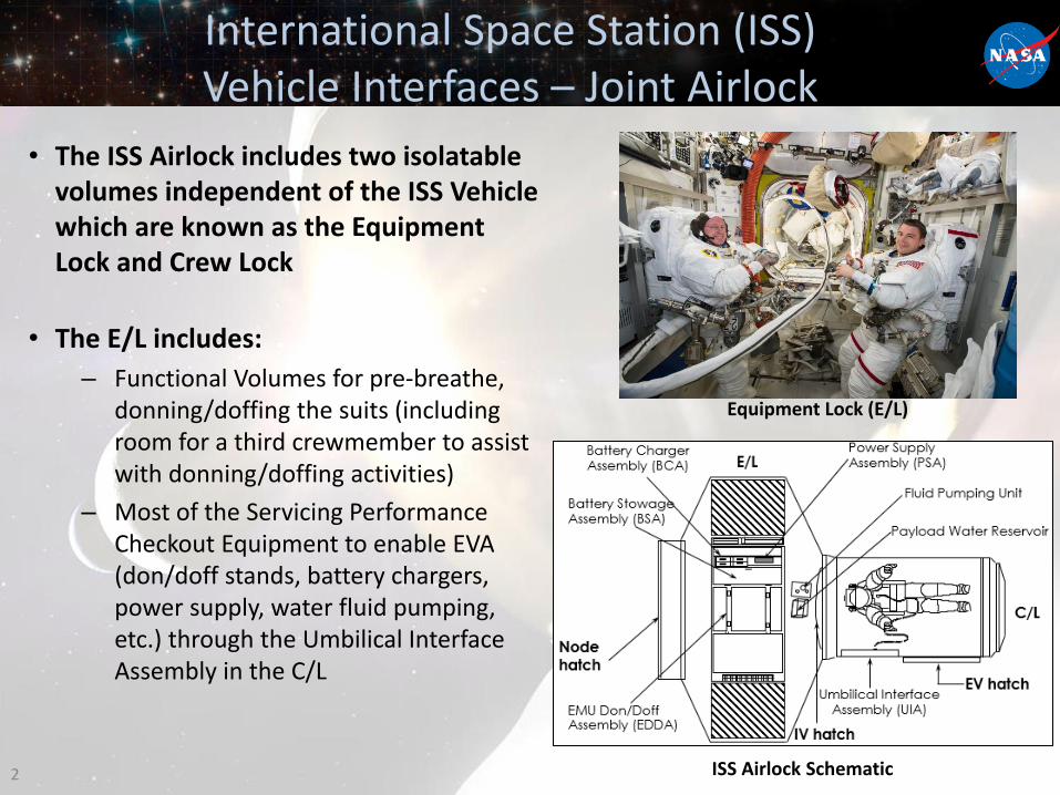
International Space Station (ISS) Vehicle Interfaces – Joint Airlock
• The ISS Airlock includes two isolatable volumes independent of the ISS Vehicle which are known as the Equipment Lock and Crew Lock
• The E/L includes:
– Functional Volumes for pre-breathe, donning/doffing the suits (including room for a third crewmember to assist with donning/doffing activities)
– Most of the Servicing Performance Checkout Equipment to enable EVA (don/doff stands, battery chargers, power supply, water fluid pumping, etc.) through the Umbilical Interface Assembly in the C/L
2
Equipment Lock (E/L)
ISS Airlock Schematic
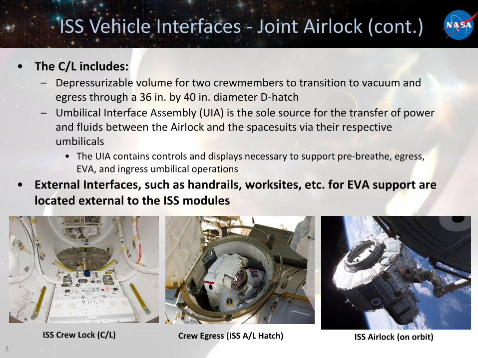
ISS Vehicle Interfaces - Joint Airlock (cont.)
• The C/L includes:– Depressurizable volume for two crewmembers to transition to vacuum and
egress through a 36 in. by 40 in. diameter D-hatch
– Umbilical Interface Assembly (UIA) is the sole source for the transfer of power and fluids between the Airlock and the spacesuits via their respective umbilicals
• The UIA contains controls and displays necessary to support pre-breathe, egress, EVA, and ingress umbilical operations
• External Interfaces, such as handrails, worksites, etc. for EVA support are located external to the ISS modules
ISS Airlock (on orbit)3
Crew Egress (ISS A/L Hatch)ISS Crew Lock (C/L)
Interface Definition Document
• Developing a draft document called the Interface Definition Document (IDD) in order to provide a resource for identifying spacecraft to EVA interfaces
• The main purpose of the IDD is to define the EVA interfaces of the ISS to assist in understanding changes to ISS to enable future demonstrations and also can act as a spring board for future spacecraft interface development
• The document is broken into three volumes: – “Where we are” - Defines current ISS interfaces and capabilities related to EVA
• This extends beyond the airlock to interfacing tools and EVA suit peripherals
• Coalesces information from multiple SoA Interface Control Documents and sources into one location
– “Where we want to go” - Identifies future suit desired interfaces and desired airlock capabilities
– “Where we end up” - Captures ISS interfaces and capabilities at a future date –Content of this section is in the vein of an ICD
• “Where we want to go" includes ISS UIA upgrades to scar for high pressure O2 as well as vacuum access studies to assess vacuum ports in support of a Rapid Cycle Amine CO2 removal demonstration
4
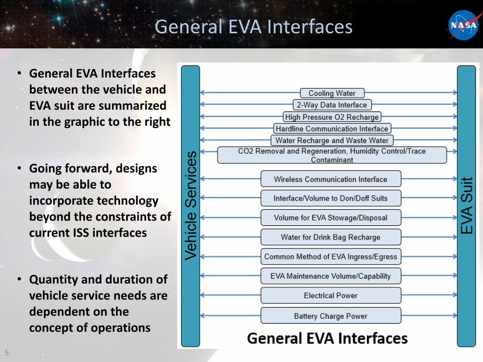
General EVA Interfaces
• General EVA Interfaces between the vehicle and EVA suit are summarized in the graphic to the right
• Going forward, designs may be able to incorporate technology beyond the constraints of current ISS interfaces
• Quantity and duration of vehicle service needs are dependent on the concept of operations
5
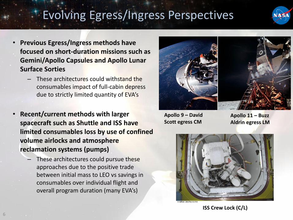
Evolving Egress/Ingress Perspectives
• Previous Egress/Ingress methods have focused on short-duration missions such as Gemini/Apollo Capsules and Apollo Lunar Surface Sorties
– These architectures could withstand the consumables impact of full-cabin depress due to strictly limited quantity of EVA’s
• Recent/current methods with larger spacecraft such as Shuttle and ISS have limited consumables loss by use of confined volume airlocks and atmosphere reclamation systems (pumps)
– These architectures could pursue these approaches due to the positive trade between initial mass to LEO vs savings in consumables over individual flight and overall program duration (many EVA’s)
6
Apollo 9 – David Scott egress CM
Apollo 11 – Buzz Aldrin egress LM
ISS Crew Lock (C/L)
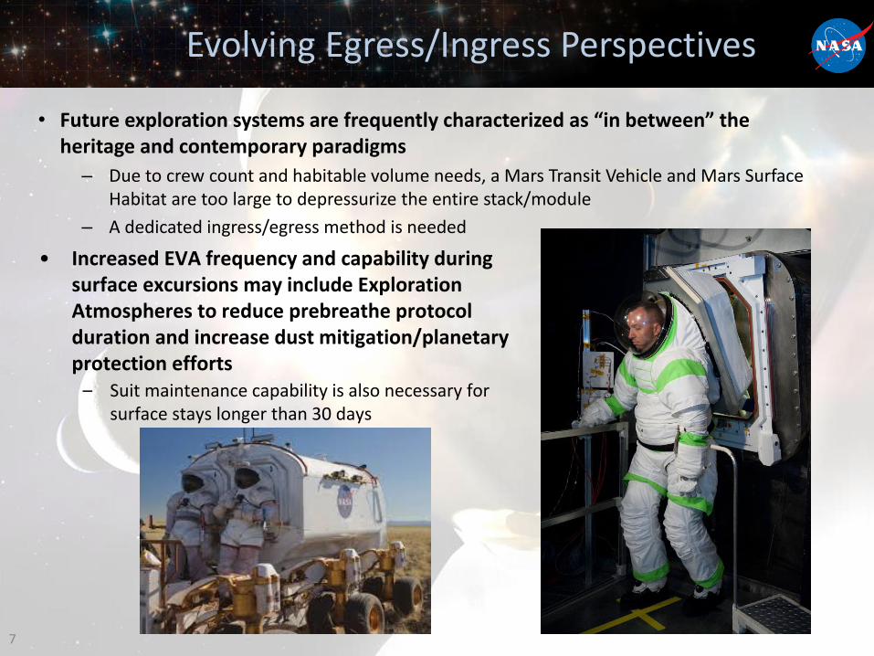
Evolving Egress/Ingress Perspectives
• Future exploration systems are frequently characterized as “in between” the heritage and contemporary paradigms
– Due to crew count and habitable volume needs, a Mars Transit Vehicle and Mars Surface Habitat are too large to depressurize the entire stack/module
– A dedicated ingress/egress method is needed
7
• Increased EVA frequency and capability during surface excursions may include Exploration Atmospheres to reduce prebreathe protocol duration and increase dust mitigation/planetary protection efforts
– Suit maintenance capability is also necessary for surface stays longer than 30 days
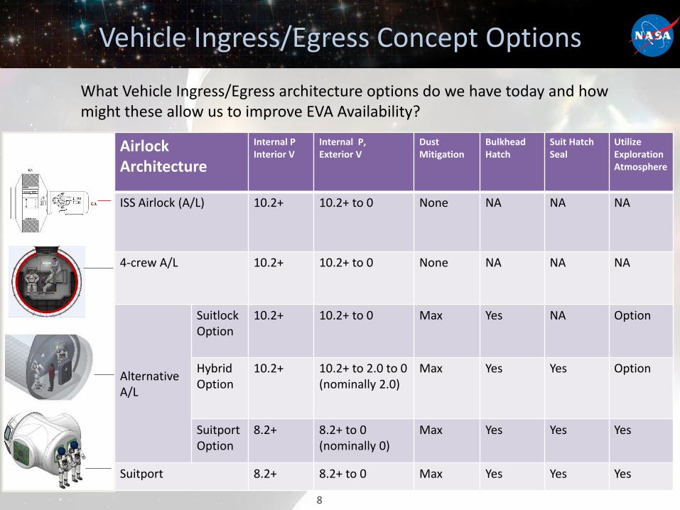
Vehicle Ingress/Egress Concept Options
8
Airlock Architecture
Internal P Interior V
Internal P, Exterior V
DustMitigation
Bulkhead Hatch
Suit Hatch Seal
UtilizeExploration Atmosphere
ISS Airlock (A/L) 10.2+ 10.2+ to 0 None NA NA NA
4-crew A/L 10.2+ 10.2+ to 0 None NA NA NA
Alternative A/L
SuitlockOption
10.2+ 10.2+ to 0 Max Yes NA Option
Hybrid Option
10.2+ 10.2+ to 2.0 to 0(nominally 2.0)
Max Yes Yes Option
Suitport Option
8.2+ 8.2+ to 0(nominally 0)
Max Yes Yes Yes
Suitport 8.2+ 8.2+ to 0 Max Yes Yes Yes
What Vehicle Ingress/Egress architecture options do we have today and how might these allow us to improve EVA Availability?
Conclusions
• Heritage and SoA EVA to vehicle interfaces are being built upon through lessons learned and technology development upgrades
• The EVA-ISS Interface Definition Document notes the current interface architecture with which EVA operates and acts as an assessment starting point for identifying interface deltas between current capability and future missions interface architectures
• A wide range of vehicle ingress/egress options are being considered for future operational concepts and mission drivers
9
BACKUP
10
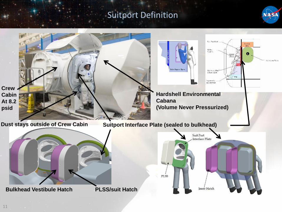
Suitport Definition
11
Suitport Interface Plate (sealed to bulkhead)
Hardshell Environmental
Cabana
(Volume Never Pressurized)
Crew
Cabin
At 8.2
psid
PLSS/suit HatchBulkhead Vestibule Hatch
Dust stays outside of Crew Cabin
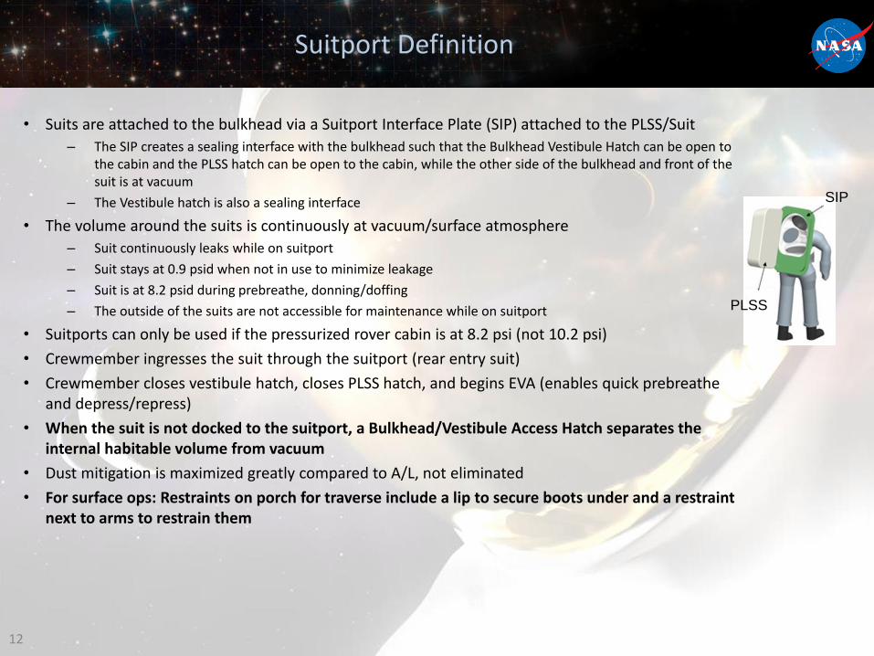
Suitport Definition
• Suits are attached to the bulkhead via a Suitport Interface Plate (SIP) attached to the PLSS/Suit
– The SIP creates a sealing interface with the bulkhead such that the Bulkhead Vestibule Hatch can be open to the cabin and the PLSS hatch can be open to the cabin, while the other side of the bulkhead and front of the suit is at vacuum
– The Vestibule hatch is also a sealing interface
• The volume around the suits is continuously at vacuum/surface atmosphere
– Suit continuously leaks while on suitport
– Suit stays at 0.9 psid when not in use to minimize leakage
– Suit is at 8.2 psid during prebreathe, donning/doffing
– The outside of the suits are not accessible for maintenance while on suitport
• Suitports can only be used if the pressurized rover cabin is at 8.2 psi (not 10.2 psi)
• Crewmember ingresses the suit through the suitport (rear entry suit)
• Crewmember closes vestibule hatch, closes PLSS hatch, and begins EVA (enables quick prebreathe and depress/repress)
• When the suit is not docked to the suitport, a Bulkhead/Vestibule Access Hatch separates the internal habitable volume from vacuum
• Dust mitigation is maximized greatly compared to A/L, not eliminated
• For surface ops: Restraints on porch for traverse include a lip to secure boots under and a restraint next to arms to restrain them
12
SIP
PLSS
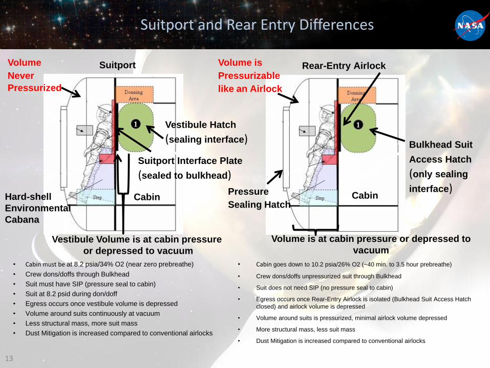
Suitport and Rear Entry Differences
• Cabin must be at 8.2 psia/34% O2 (near zero prebreathe)
• Crew dons/doffs through Bulkhead
• Suit must have SIP (pressure seal to cabin)
• Suit at 8.2 psid during don/doff
• Egress occurs once vestibule volume is depressed
• Volume around suits continuously at vacuum
• Less structural mass, more suit mass
• Dust Mitigation is increased compared to conventional airlocks
13
• Cabin goes down to 10.2 psia/26% O2 (~40 min. to 3.5 hour prebreathe)
• Crew dons/doffs unpressurized suit through Bulkhead
• Suit does not need SIP (no pressure seal to cabin)
• Egress occurs once Rear-Entry Airlock is isolated (Bulkhead Suit Access Hatch
closed) and airlock volume is depressed
• Volume around suits is pressurized, minimal airlock volume depressed
• More structural mass, less suit mass
• Dust Mitigation is increased compared to conventional airlocks
Suitport Rear-Entry Airlock
Cabin
Bulkhead Suit
Access Hatch
(only sealing
interface)
Vestibule Volume is at cabin pressure
or depressed to vacuum
Volume is at cabin pressure or depressed to
vacuum
Suitport Interface Plate
(sealed to bulkhead)
Vestibule Hatch
(sealing interface)
Volume is
Pressurizable
like an Airlock
Volume
Never
Pressurized
CabinPressure
Sealing HatchHard-shell
Environmental
Cabana
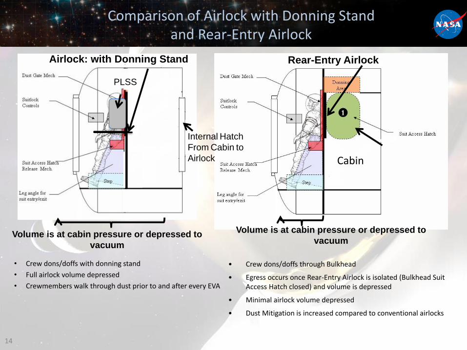
Comparison of Airlock with Donning Stand and Rear-Entry Airlock
• Crew dons/doffs with donning stand
• Full airlock volume depressed
• Crewmembers walk through dust prior to and after every EVA
14
• Crew dons/doffs through Bulkhead
• Egress occurs once Rear-Entry Airlock is isolated (Bulkhead Suit Access Hatch closed) and volume is depressed
• Minimal airlock volume depressed
• Dust Mitigation is increased compared to conventional airlocks
Airlock: with Donning Stand Rear-Entry Airlock
Internal Hatch
From Cabin to
Airlock Cabin
Volume is at cabin pressure or depressed to
vacuum
Volume is at cabin pressure or depressed to
vacuum
PLSS
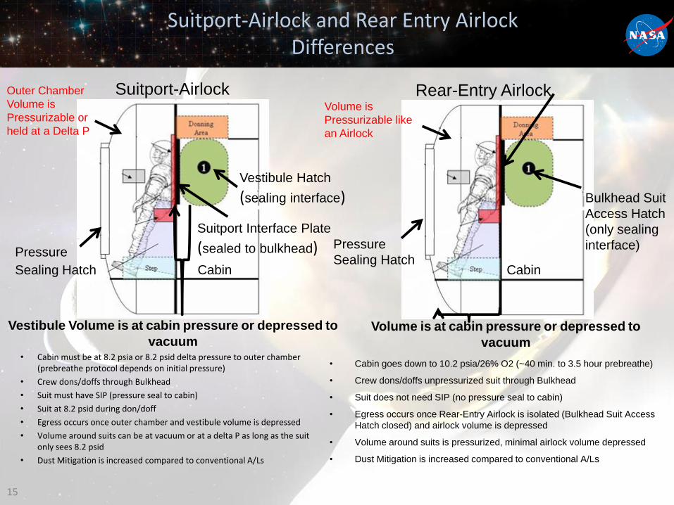
Suitport-Airlock and Rear Entry Airlock Differences
• Cabin must be at 8.2 psia or 8.2 psid delta pressure to outer chamber (prebreathe protocol depends on initial pressure)
• Crew dons/doffs through Bulkhead
• Suit must have SIP (pressure seal to cabin)
• Suit at 8.2 psid during don/doff
• Egress occurs once outer chamber and vestibule volume is depressed
• Volume around suits can be at vacuum or at a delta P as long as the suit only sees 8.2 psid
• Dust Mitigation is increased compared to conventional A/Ls
15
• Cabin goes down to 10.2 psia/26% O2 (~40 min. to 3.5 hour prebreathe)
• Crew dons/doffs unpressurized suit through Bulkhead
• Suit does not need SIP (no pressure seal to cabin)
• Egress occurs once Rear-Entry Airlock is isolated (Bulkhead Suit Access
Hatch closed) and airlock volume is depressed
• Volume around suits is pressurized, minimal airlock volume depressed
• Dust Mitigation is increased compared to conventional A/Ls
Suitport-Airlock Rear-Entry Airlock
Cabin
Bulkhead Suit
Access Hatch
(only sealing
interface)
Vestibule Volume is at cabin pressure or depressed to
vacuumVolume is at cabin pressure or depressed to
vacuum
Suitport Interface Plate
(sealed to bulkhead)
Vestibule Hatch
(sealing interface)
Volume is
Pressurizable like
an Airlock
Cabin
Pressure
Sealing HatchPressure
Sealing Hatch
Outer Chamber
Volume is
Pressurizable or
held at a Delta P
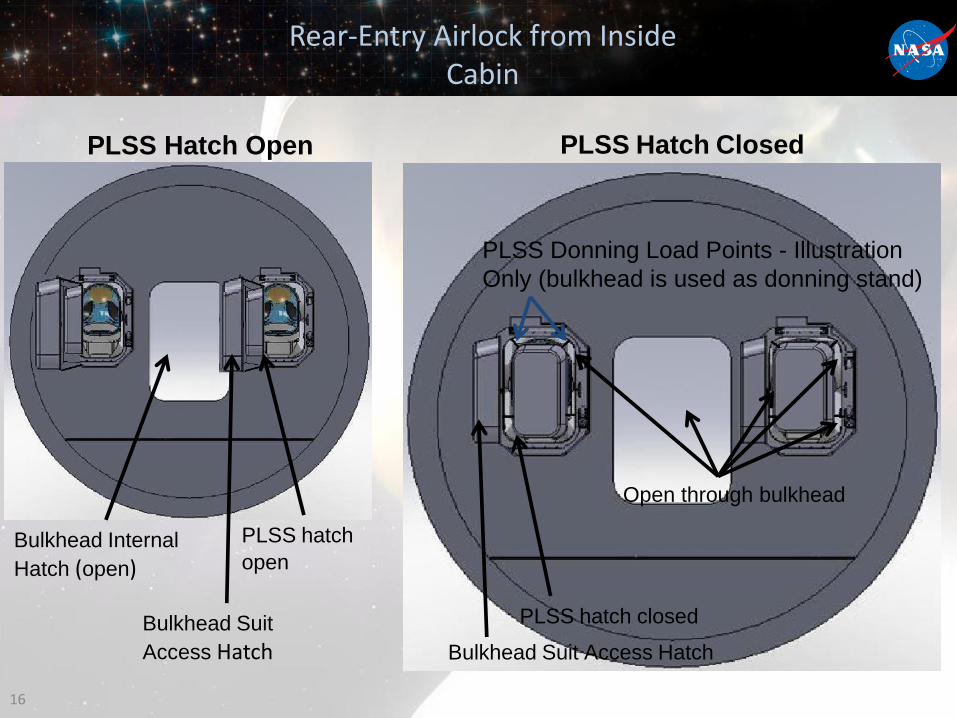
Rear-Entry Airlock from Inside Cabin
16
PLSS hatch
open
Bulkhead Suit
Access Hatch
PLSS hatch closed
Bulkhead Suit Access Hatch
PLSS Donning Load Points - Illustration
Only (bulkhead is used as donning stand)
Open through bulkhead
Bulkhead Internal
Hatch (open)
PLSS Hatch Open PLSS Hatch Closed
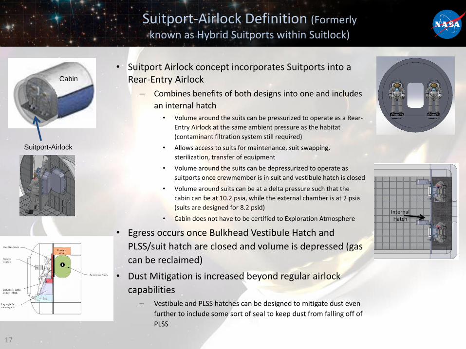
Suitport-Airlock Definition (Formerly
known as Hybrid Suitports within Suitlock)
• Suitport Airlock concept incorporates Suitports into a Rear-Entry Airlock
– Combines benefits of both designs into one and includes
an internal hatch
• Volume around the suits can be pressurized to operate as a Rear-
Entry Airlock at the same ambient pressure as the habitat
(contaminant filtration system still required)
• Allows access to suits for maintenance, suit swapping,
sterilization, transfer of equipment
• Volume around the suits can be depressurized to operate as
suitports once crewmember is in suit and vestibule hatch is closed
• Volume around suits can be at a delta pressure such that the
cabin can be at 10.2 psia, while the external chamber is at 2 psia
(suits are designed for 8.2 psid)
• Cabin does not have to be certified to Exploration Atmosphere
• Egress occurs once Bulkhead Vestibule Hatch and
PLSS/suit hatch are closed and volume is depressed (gas
can be reclaimed)
• Dust Mitigation is increased beyond regular airlock
capabilities
– Vestibule and PLSS hatches can be designed to mitigate dust even
further to include some sort of seal to keep dust from falling off of
PLSS
17
Cabin
Suitport-Airlock
Internal Hatch