Embed Size (px)
Citation preview
Evaluating Fire Resistance of Steel Girders in BridgesVenkatesh Kodur, F.ASCE1; Esam Aziz2; and Mahmud Dwaikat3
Abstract: In current practice, no special measures are applied for enhancing structural fire safety of steel bridge girders. Further, there is verylimited information and research data in the literature on the fire resistance of structural members in bridges. In this paper, the fire response ofa steel bridge girder under different conditions is evaluated using the FEM computer program ANSYS. In the analysis, the critical factors thatinfluence fire resistance, namely, fire scenario, fire insulation, and composite action arising from steel-concrete interaction, are accounted for.Results from numerical studies show that the composite action arising from steel-girder–concrete-slab interaction significantly enhances thestructural performance (and fire resistance) of a steel bridge girder under fire conditions. Other significant factors that influence fire resistance ofsteel bridge girders are fire insulation and type of fire scenario.DOI: 10.1061/(ASCE)BE.1943-5592.0000412. © 2013 American Society ofCivil Engineers.
CE Database subject headings: Fires; Fire resistance; Girder bridges; Steel bridges.
Author keywords: Bridge fires; Fire resistance; Steel girders; FEM analysis.
Introduction
Fire is one of the most severe environmental hazards to which thebuilt infrastructure may be subjected during its lifetime. In recentdecades, due to rapid development of urban ground-transportationsystems, as well as increasing transportation of hazardous ma-terials (e.g.,flammable liquids, spontaneously combustiblematerials,poisonous substances, etc.), bridge fires have become a growingconcern (Kodur et al. 2010). Whereas the perception may be thatit is very unlikely that a bridge will collapse under fire, a recentU.S.-wide surveyby theNewYorkStateDepartment ofTransportation(NYDoT) has shown that nearly three times more bridges havecollapsed in the 1990–2005 period due to fire than due to earthquakes(M. Garlock, personal communication, 2008). In some cases, bridgefiresmight lead to the collapse of structuralmembers, leading tomajortraffic delays, detours, and costly repairs. The following fire incidentsillustrate the magnitude of fire problem in bridges.
On July 15, 2009, a tanker truck carrying 13,000 gal of flam-mable liquid was involved in an accident with another truck underthe 9-mi road overpass over the I-75 expressway near Hazel Park,Michigan. This bridge consisted of 10 hot-rolled steel girders ina 24-m span that supported a RC slab. The intense heat from the firereached about 1,100�C, and this heat led to weakening of the steelgirders and resulted in collapse of the overpass, as illustrated inFig. 1. This collapse occurred in about 20 min after the start of thefire. It took about 105 min for the firefighters to extinguish the fire.
This accident caused millions of dollars of damage. Preliminaryrecommendations called for rebuilding the entire 9-mi bridge over I-75, and the freeway below also needed some level of repair. It tookseveral weeks of detours on I-75 and several months for repair of thebridge (National Steel Bridge Alliance 2010).
Another example of fire-induced bridge collapse is the one thatoccurred on the MacArthur Maze I-80/880 interchange in Oakland,California, on April 29, 2007. A tanker truck carrying 8,600 gal ofgasoline overturned underneath the I-580 expressway, which con-sisted of six plate girders supporting a RC roadway. The firefightersresponded to the spot within 14 min, but the intense fire from theaccident resulted in temperatures reaching 1,100�C. This intenseheat lead to loss of strength in the steel girders, and ultimately, theconnections at the supports gave way, leading to collapse of two I-580 spans. The failure occurred at 22 min into the fire. Preliminaryanalysis revealed that the failure was due to overstressing of con-nections under high-temperature effects. This incident cost $9million to repair the bridge, and the retrofitting took months to finish(Astaneh-Asl et al. 2009).
The response of bridge structural members under fire can bedifferent from that of buildings for the following reasons:1. Fire source: The common source of ignition in bridges is
the crashing of gasoline tanker trucks and burning of gasolinein the vicinity of the bridge. However, the common sourceof ignition in buildings is the burning of combustion ma-terials (mostly wood and plastic-based products) in thecompartment.
2. Fire ventilation: Most building fires are enclosed (compart-ment fires) and are limited by the amount of ventilation.However, bridge fires are generally under open-air conditionsand have unlimited access to ventilation (oxygen).
3. Fire severity: Bridge fires can be much more intense thanbuilding fires and are representative of hydrocarbon firesbecause the fire source is generally gasoline.
4. Fire protection: In contrast to buildings, which are providedwith active fire-protection systems such as sprinklers andpassive fire protection such as fire insulation, no specialfire-protection measures are provided in bridges.
5. Failure limit state: Bridge girders are much deeper than beamsin buildings and may have quite slender webs. As a result,
1Professor, Dept. of Civil and Environmental Engineering, MichiganState Univ., East Lansing, MI 48864 (corresponding author). E-mail:[email protected]
2Ph.D. Candidate, Dept. of Civil and Environmental Engineering,Michigan State Univ., East Lansing,MI 48864. E-mail: [email protected]
3Researcher, Delft University, 2600AADelft, Netherlands; formerly, PostDoctoral Fellow, Dept. of Civil and Environmental Engineering, MichiganState Univ., East Lansing, MI 48864. E-mail: [email protected]
Note. This manuscript was submitted on September 30, 2011; approvedon April 23, 2012; published online on April 26, 2012. Discussion periodopen until December 1, 2013; separate discussions must be submitted forindividual papers. This paper is part of the Journal of Bridge Engineering,Vol. 18, No. 7, July 1, 2013. ©ASCE, ISSN 1084-0702/2013/7-633–643/$25.00.
JOURNAL OF BRIDGE ENGINEERING © ASCE / JULY 2013 / 633
J. Bridge Eng. 2013.18:633-643.
Dow
nloa
ded
from
asc
elib
rary
.org
by
UN
IVE
RSI
TY
OF
HO
UST
ON
on
02/2
1/14
. Cop
yrig
ht A
SCE
. For
per
sona
l use
onl
y; a
ll ri
ghts
res
erve
d.

shear failure due to web buckling is likely to dominate inbridge girders, whereas flexural failure is the dominant failuremechanism in beams.
6. Connections: Bridge girders are typically supported throughbearing of the bottom flange. In contrast, the connections inbuildings are made through the web and/or the flange. Thesevariations in support conditions have an effect on the resultingfire resistance (Paya-Zaforteza and Garlock 2010).
A review of literature indicates that there is a lack of informationon the fire performance of bridge girders, and this is mainly due tothe fact that little attention has been paid to structural fire safety inbridges. The limited studies on the fire resistance of bridges are thosereported by Dotreppe et al. (2006), Kodur et al. (2010), and Paya-Zaforteza and Garlock (2010). These studies clearly indicate thatbridge fires are a significant problem and typically result from thecrashing of vehicles in the vicinity of the bridge. The time to failure istypically less than 30 min, and thus very little time is available forfirefighters to respond. Further, there is lack of data on the firebehavior of bridge girders as well as on the main factors that in-fluence fire resistance. To overcome some of these drawbacks, aresearch project on the fire performance of steel bridges is currentlyunder way at Michigan State University. This paper presents resultsfrom a numerical study on the fire performance of steel bridgegirders.
FEM Model
To illustrate the response of a steel girder exposed tofire, a numericalstudy was carried out using the FEM computer program ANSYS(ANSYS multiphysics, 11.0 SP1). This program is capable of han-dling coupled and uncoupled thermomechanical problems. For theanalysis, a simply supported steel bridge girder was selected. Thisbridge girder is generally comprised of different structural com-ponents, namely, girder, RC slab, and intermediate diaphragms.Two sets of discretization models were developed for undertakingthermal and mechanical analyses. The thermal-analysis results areapplied as a thermal-body load on the structural model uniformlyalong the girder span. High-temperature thermal and mechanicalproperties of steel, concrete, and insulation were incorporated in theanalysis. Strength limit statewas adopted for defining failure, and thefailure is said to occur when the girder is unable to resist the appliedload effects.
Discretization for Thermal Analysis
The heat-transfer analysis of the selected composite steel–concretegirder was carried out for two cases, namely, with and withoutstiffeners. For the discretization of the girder, slab, and stiffeners,SOLID70 elements were used. SOLID70 is a three-dimensional (3D)element with 3D thermal conduction capability and has eight nodeswith a single degree of freedom, namely, temperature, at each node.This element is applicable to 3D steady-state or transient thermalanalysis. The external surface areas of the SOLID70 elements thatare exposed to fire, except the top surface of the slab, were used tosimulate the surface effects of convection and radiation that occurfrom the ambient air to the steel girder. The discretization adopted forthe thermal model is shown in Fig. 2.
The girder-slab assembly segment AB shown in Fig. 2(b) wasmeshed with SOLID70 elements. Both heat-convection and radia-tion loads were applied at the exposed surface areas of the solidelement. Convection coefficients of ac 5 50W=ðm2�CÞ and ac 535W=ðm2�CÞ were used in the thermal analysis under hydrocarbonand external fire, respectively, and this is based on Eurocode 1[European Committee for Standardization (CEN) 2002] recom-mendations. Depending on the exposure boundaries, differentvalues of effective emissivity factor were used (CEN 2002). Aneffective emissivity factor of 0.7 was used for the bottom and sidesurfaces of the bottomflange of the girder. For the side surfaces of theweb, an emissivity factor of 0.5was used, whereas a factor of 0.3wasused for the top flange and bottom of the slab. This variation inemissivity factor is to reflect the fact that theweb, topflange, and slabwill experience slightly less radiation due to the effect of the largergirder depth of the girder section. A Stefan-Boltzmann radiation con-stant of 5:673 1028 W=ðm2�CÞ was applied in the thermal analysis.
The thermal properties of steel and concrete, namely, thermalconductivity, specific heat, and thermal expansion, vary with
Fig. 1.Fire-induced girder collapse inHazel Park overpass inMichigan(photograph from Zapletal 2009)
Fig. 2. Three-dimensional discretization of girder cross section forthermal analysis: (a) typical girder in a bridge; (b) 3Dmeshof segmentAB
634 / JOURNAL OF BRIDGE ENGINEERING © ASCE / JULY 2013
J. Bridge Eng. 2013.18:633-643.
Dow
nloa
ded
from
asc
elib
rary
.org
by
UN
IVE
RSI
TY
OF
HO
UST
ON
on
02/2
1/14
. Cop
yrig
ht A
SCE
. For
per
sona
l use
onl
y; a
ll ri
ghts
res
erve
d.

temperature. In the analysis, the high-temperature properties areassumed to follow according to Eurocode 2 (CEN 2004) andEurocode 3 (CEN 2005) provisions. The temperatures T obtainedvia FEM analysis were averaged at every time step of fire exposureby taking the arithmetic mean of the temperatures at several pointsfor each component (i.e., flange, web, or slab portion) of the steelgirder–concrete slab composite section, as shown in Fig. 3.
Discretization for Structural Analysis
For structural analysis, the bridge girder was modeled with twoelements, namely, element SHELL181 for the bottom flange, web,topflange, and stiffeners and element SOLID65 for the concrete slab.SHELL181 has four nodes with six degrees of freedom per node,three translations in x-, y-, and z-directions, and three rotations about
the x-, y-, and z-axes. This element can capture buckling offlange andweb as well as lateral torsional buckling of themember and thereforeiswell suited for large-rotation, large-strain, and nonlinear problems.SOLID65 has eight nodes with three degrees of freedom, namely,three translations in the x-, y-, and z-directions. This element can beused for 3D modeling of solids with or without reinforcement and iscapable of accounting for cracking of concrete in tension, crushingof concrete in compression, creep, and large strains. The output fromthe thermal analysis (temperatures) was applied as a thermal-bodyload on the structural model to evaluate the mechanical response ofa steel-concrete composite girder. The 3D structural model and themeshing adopted in the analysis are shown in Fig. 4(a).
To account for composite action between the concrete slab andthe top flange of the steel girder, node-to-node interaction was dis-cretized in the structural model as shown in Fig. 4(b). The same nodesare shared between the solid elements of the concrete slab and theshell elements of the top flange of the steel girder. To discretize theboundary condition in the structural FEM model, the support con-ditions of the bridge girder were applied on multiline nodes at thelower face of the bottom flange, as shown in Fig. 4(c). This boundarycondition reflects a practical scenario, reduces the stress concentrationat the boundary-conditionnodes, and improves the convergence of theFEM solution. Also, to consider the continuity effect of the concreteslab, the slab was restrained from lateral movement [see Fig. 4(c)].
Material Properties
The progression of temperatures in the steel section under fire ex-posure depends on the fire scenario and the thermal properties ofconstituent materials, namely, thermal conductivity, specific heat,and thermal expansion, which vary as a function of temperature. Themechanical properties of steel and concrete that are critical for
Fig. 3. Averaging the temperature in the girder cross section
Fig. 4. Three-dimensional discretization of bridge girder for structural analysis: (a) 3D mesh; (b) composite-action simulation; (c) support andboundary condition
JOURNAL OF BRIDGE ENGINEERING © ASCE / JULY 2013 / 635
J. Bridge Eng. 2013.18:633-643.
Dow
nloa
ded
from
asc
elib
rary
.org
by
UN
IVE
RSI
TY
OF
HO
UST
ON
on
02/2
1/14
. Cop
yrig
ht A
SCE
. For
per
sona
l use
onl
y; a
ll ri
ghts
res
erve
d.

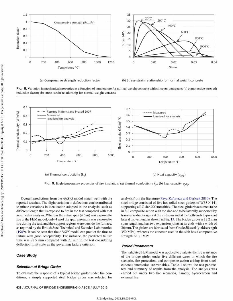
fire-resistance evaluation are stress-strain relationships andmodulusof elasticity, which also vary with temperature. The temperature-dependent thermal and mechanical properties of steel and concreteare assumed to follow the Eurocode 2 (CEN 2004) and Eurocode 3(CEN 2005) provisions. The thermal conductivity, specific heat,thermal expansion, and stress-strain curves of structural steel andconcrete used in the analysis are given in Figs. 5–8. The fire insulationapplied on the steel girder is CAFCO 300, and this insulation hasa specified thermal conductivity of 0.078 W/(m �C) and a density of240 kg/m3 at room temperature (Isolatek International 2008).CAFCO300 is typically used for interior applications, but the thermalproperties (i.e., thermal conductivity and specific heat) of this type ofinsulation used in exterior applications are quite similar to those ofthe insulation used in interior applications. The high-temperaturethermal properties of the insulation (both thermal conductivity andspecific heat) were assumed to follow the recommendations of Bentzand Prasad (2007). The temperature-dependent thermal conductivityand specific-heat value of the insulation used in the analysis is plottedin Fig. 9 as a function of temperature.
Model Validation
There is lack of fire test data on the responses of bridge girdersunder fire conditions. Therefore, validation of the ANSYS model wedeveloped was carried out by selecting a steel-beam–concrete-slab assembly tested by British Steel Corporation (British SteelTechnical and Swinden Laboratories 1989). This beam-slab
assembly, typical of that in buildings, was tested under ISO 834(ISO 1975) fire exposure. The validation process included com-parison of both thermal and structural response predictions from theanalysis with that reported in the fire test. The steel beam was notinsulated. The beam-slab assembly, together with thermocouplelayout, used in the test formeasuring temperatures is shown in Fig. 10.The analysis was carried out with the mesh discretization and high-temperature properties discussed earlier. The assembly was exposedto ISO 834 fire exposure as in the fire test.
Fig. 11 shows a comparison of predicted steel temperatures by theFEM model with those measured in the fire test. It can be seen thatthe top flange of the beam experienced much lower temperaturescompared with the bottom flange, and this is due to the effect of theconcrete slab, which dissipates the temperature in the top flangebecause of the lower thermal conductivity and higher thermal ca-pacity of concrete compared with steel. The web temperatures areslightly higher than those in the bottom flange, and this is due to thefact that the thickness of theweb ismuch less than that of the flanges.Overall, the predicted temperatures from the analysis compare wellwith the measured data from the test. The slight difference can beattributed to variation in the heat-transfer parameters, such asemissivity and convection coefficients, used in the analysiscompared with the actual values in the test (furnace).
A comparison of midspan deflections predicted by the ANSYSmodel and those measured in the test is shown in Fig. 12. It can beseen that the midspan deflection gradually increases with time in theearly stage of the fire (up to 10 min). These initial deflections are
Fig. 5. Variation in thermal properties as a function of temperature for carbon steel: (a) thermal conductivity; (b) specific heat; (c) thermal expansion
636 / JOURNAL OF BRIDGE ENGINEERING © ASCE / JULY 2013
J. Bridge Eng. 2013.18:633-643.
Dow
nloa
ded
from
asc
elib
rary
.org
by
UN
IVE
RSI
TY
OF
HO
UST
ON
on
02/2
1/14
. Cop
yrig
ht A
SCE
. For
per
sona
l use
onl
y; a
ll ri
ghts
res
erve
d.

mainly due to high temperature gradients that develop between thetop and bottom flanges of the steel section and the slight reduction inelastic modulus of steel resulting from increased temperatures in thegirder. After 10 min, the rate of deflection increases slightly due tospread of plasticity, which results in faster strength and stiffness
degradation of steel at high temperatures. At about 21 min when thebottom flange and web temperatures are about 600�C, the midspandeflection increases rapidly due to the effect of high-temperaturecreep, and failure of the girder occurs at 23 min through the for-mation of a plastic hinge at the midspan section.
Fig. 6. Variation in mechanical properties as a function of temperature for carbon steel: (a) yield strength and elastic-modulus reduction factor;(b) stress-strain relationship for Grade 50 steel
Fig. 7. Variation in thermal properties as a function of temperature for normal-weight concrete with siliceous aggregate: (a) thermal conductivity;(b) specific heat; (c) thermal expansion
JOURNAL OF BRIDGE ENGINEERING © ASCE / JULY 2013 / 637
J. Bridge Eng. 2013.18:633-643.
Dow
nloa
ded
from
asc
elib
rary
.org
by
UN
IVE
RSI
TY
OF
HO
UST
ON
on
02/2
1/14
. Cop
yrig
ht A
SCE
. For
per
sona
l use
onl
y; a
ll ri
ghts
res
erve
d.
Overall, predictions from the ANSYS model match well with thereported test data. The slight variation in deflections can be attributedto minor variations in idealization adopted in the analysis, such asdifferent length that is exposed to fire in the test compared with thatassumed in analysis.Whereas the entire span (4.5m) was exposed tofire in the FEMmodel, only 4mof the span assemblywas exposed tofire during the test, and the support regions were outside the furnace,as reported by the British Steel Technical and Swinden Laboratories(1989). It can be seen that the ANSYS model can predict the time tofailure with good acceptability. For instance, the predicted failuretime was 22.5 min compared with 23 min in the test consideringdeflection limit state as the governing failure criterion.
Case Study
Selection of Bridge Girder
To evaluate the response of a typical bridge girder under fire con-ditions, a simply supported steel bridge girder was selected for
analysis from the literature (Paya-Zaforteza and Garlock 2010). Thesteel bridge consisted of five hot-rolled steel girders of W333 141supporting a RC slab 200mm thick. The steel girder is assumed to bein full composite actionwith the slab and to be laterally supported bytransverse diaphragms at themidspan and at the both ends to preventlateral movement, as shown in Fig. 13. The bridge girder is 12.2m inspan length and has two expansion joints at its ends with a width of36mm.The girders are fabricated fromGrade 50 steel (yield strength350 MPa), whereas the concrete used in the slab has a compressivestrength of 30 MPa.
Varied Parameters
The validated FEMmodel was applied to evaluate the fire resistanceof the bridge girder under five different cases in which the firescenario, fire protection, and composite action arising from steel-concrete interaction are variables. Table 1 shows the test parame-ters and summary of results from the analysis. The analysis wascarried out under two fire scenarios, namely, hydrocarbon andexternal fire.
Fig. 8.Variation in mechanical properties as a function of temperature for normal-weight concrete with siliceous aggregate: (a) compressive-strengthreduction factor; (b) stress-strain relationship for normal-weight concrete
Fig. 9. High-temperature properties of fire insulation: (a) thermal conductivity kp; (b) heat capacity rpcp
638 / JOURNAL OF BRIDGE ENGINEERING © ASCE / JULY 2013
J. Bridge Eng. 2013.18:633-643.
Dow
nloa
ded
from
asc
elib
rary
.org
by
UN
IVE
RSI
TY
OF
HO
UST
ON
on
02/2
1/14
. Cop
yrig
ht A
SCE
. For
per
sona
l use
onl
y; a
ll ri
ghts
res
erve
d.

To study the effect of the composite action arising from steelgirder–concrete slab interaction, two cases were considered. InCase 1, composite action from the slab was neglected, and thestrength analysis corresponds to that from a plain girder only. InCase 2, the effect of the slab was included by considering fullcomposite action between the steel girder and the concrete slab. In
Case 3, Case 2 was replicated under an external fire scenario toevaluate the effect of the fire scenario on the fire resistance of thegirder. External fire, which is less severe than hydrocarbon fire, canbe a possible fire scenario in bridges (CEN 2002). The time-temperature curves representing hydrocarbon and external firesare shown in Fig. 14. The effect of fire insulation on girders was
Fig. 10. Beam-slab assembly tested by British Steel Technical and Swinden Laboratories under ISO 834 fire exposure: (a) longitudinal elevation;(b) transverse section
Fig. 11. Comparison of predicted and measured cross-sectional tem-peratures in beam-slab assembly
Fig. 12. Comparison of predicted and measured midspan deflection inbeam-slab assembly
JOURNAL OF BRIDGE ENGINEERING © ASCE / JULY 2013 / 639
J. Bridge Eng. 2013.18:633-643.
Dow
nloa
ded
from
asc
elib
rary
.org
by
UN
IVE
RSI
TY
OF
HO
UST
ON
on
02/2
1/14
. Cop
yrig
ht A
SCE
. For
per
sona
l use
onl
y; a
ll ri
ghts
res
erve
d.
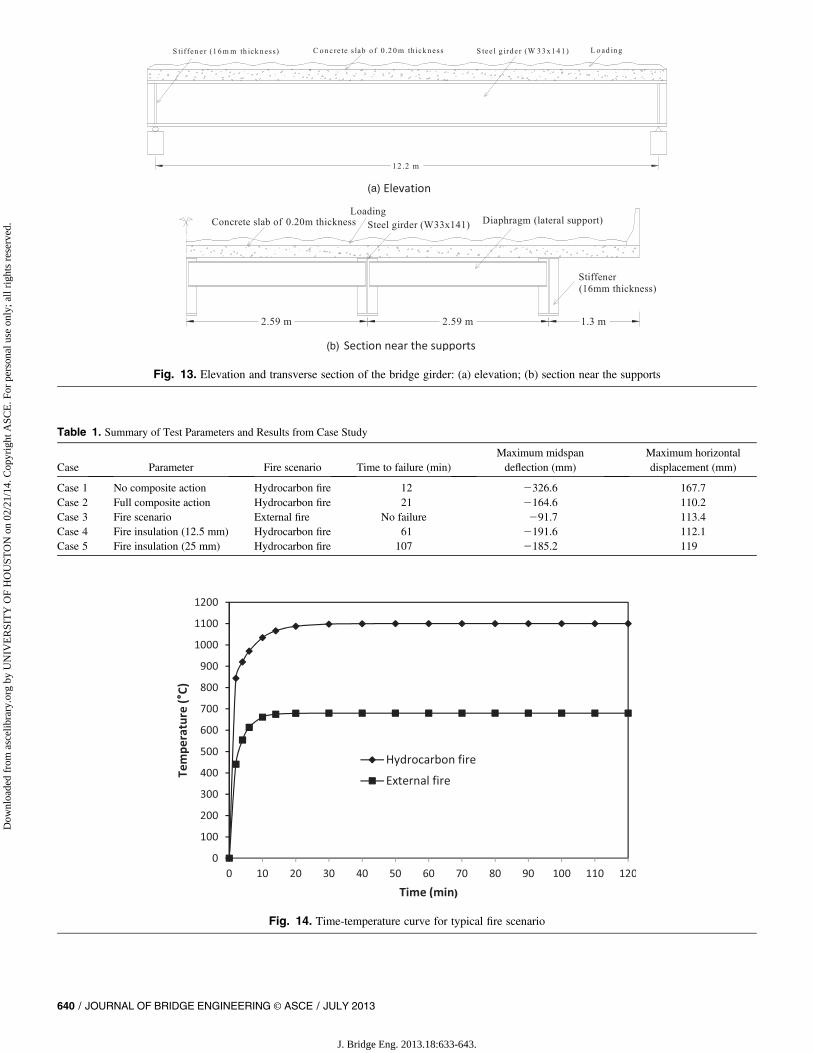
Fig. 13. Elevation and transverse section of the bridge girder: (a) elevation; (b) section near the supports
Table 1. Summary of Test Parameters and Results from Case Study
Case Parameter Fire scenario Time to failure (min)Maximum midspandeflection (mm)
Maximum horizontaldisplacement (mm)
Case 1 No composite action Hydrocarbon fire 12 2326.6 167.7Case 2 Full composite action Hydrocarbon fire 21 2164.6 110.2Case 3 Fire scenario External fire No failure 291.7 113.4Case 4 Fire insulation (12.5 mm) Hydrocarbon fire 61 2191.6 112.1Case 5 Fire insulation (25 mm) Hydrocarbon fire 107 2185.2 119
Fig. 14. Time-temperature curve for typical fire scenario
640 / JOURNAL OF BRIDGE ENGINEERING © ASCE / JULY 2013
J. Bridge Eng. 2013.18:633-643.
Dow
nloa
ded
from
asc
elib
rary
.org
by
UN
IVE
RSI
TY
OF
HO
UST
ON
on
02/2
1/14
. Cop
yrig
ht A
SCE
. For
per
sona
l use
onl
y; a
ll ri
ghts
res
erve
d.

considered in Cases 4 and 5 using two insulation thicknesses,namely, 12.5 and 25 mm.
The fire-resistance analysis on the bridge girder was carried outunder an applied loading consisting of dead load plus 30% live load.The self-weight of a girder section (2.0 kN/m) and that contributedby the tributary area of the concrete slab and wearing surface of thedeck (22.5 kN/m) were considered in the dead load according toAASHTO provisions (AASHTO 2009). For the live load, a uni-formly distributed load (9.3 kN/m) representing 0.3 times the liveload was applied.
Results and Discussion
Results from ANSYS thermal analysis for Case 2 are plotted inFig. 15, which shows the temperature distribution of the steel-concrete composite girder as a function of time for the case ofhydrocarbon fire exposure. It can be seen in Fig. 15 that the top-
flange temperature ismuch lower than that of the bottom flange. Thisis mainly due to the insulating effect of the concrete slab, whichdissipates heat from the top flange to the slab. Also, the temperaturesin theweb are slightly higher than those of the bottomflange, and thisis because the web is much more slender (lower thickness) than theflanges, and this produces a rapid rise in web temperatures.
The development of thermal gradients across the girder-slabcross section is plotted in Fig. 16 for Case 2 (noninsulated girder)and Case 4 (insulated girder) of the analysis. The thermal gradient iscomputed as the temperature difference between the middepth of theslab and the middepth of the web. At 20min, the thermal gradients is950�C in Case 2 versus 500�C in Case 4. The significant thermalgradient that develop along the depth of the cross section in Case 2results from higher temperatures in the bottom flange comparedwiththe concrete-slab temperature. However in Case 4, the presence ofinsulation minimizes the development of significant thermal gra-dients until about 60 min, at which point it reaches about 875�C.Therefore, the insulated bridge girder in Case 4 survived longer time(61 min) under fire compared with the uninsulated girder in Case 2(21 min). Thermal gradient is also influenced by the type of firescenario. This can be seen by comparing resulting temperaturegradients from Case 2 and Case 3. For Case 2 (under a hydrocarbonfire scenario), the gradient is 945�C at 60 min, whereas in Case 3(under an external fire scenario), the gradient is only 530�C at60min. This is attributed to the fact that an external fire is less severe(lower fire temperatures) compared with a hydrocarbon fire (seeFig. 14). In general, higher thermal gradients produce higher thermalstrain at the bottomof the steel girder (and in theweb) comparedwiththat in the concrete slab. Thus, a significant curvature (thermalbowing) develops in the girder, resulting in higher thermal stresseseven in a statically determinate girder (unrestrained girder). Thedeveloped curvature at the initial stage of fire exposure is in-dependent of applied load because this curvature results mostly fromthe thermal-gradient effect. Therefore, the curvature resulting fromthe thermal gradients alone contributes to the deflection at the earlystage of fire exposure. Once steel temperatures exceed 400�C, girderdeflections increase significantly due to degradation of the me-chanical properties of steel.
As shown in Fig. 16, the temperatures across the web is uniform.Results from thermal analysis show that temperature distribution
Fig. 15. Temperatures progression in a bridge girder subjected tohydrocarbon fire exposure (Case 2)
Fig. 16. Thermal gradient along the depth of a bridge girder section for Cases 2 and 4: (a) cross section; (b) Case 2; (c) Case 4
JOURNAL OF BRIDGE ENGINEERING © ASCE / JULY 2013 / 641
J. Bridge Eng. 2013.18:633-643.
Dow
nloa
ded
from
asc
elib
rary
.org
by
UN
IVE
RSI
TY
OF
HO
UST
ON
on
02/2
1/14
. Cop
yrig
ht A
SCE
. For
per
sona
l use
onl
y; a
ll ri
ghts
res
erve
d.

across the bearing stiffeners is quite similar to that in the web. This isso because of the similarity in the slenderness of stiffeners (depth andthickness) compared with that of the web. Therefore, the sametemperatures were applied to the web and the bearing stiffenersduring the structural analysis.
The structural response of a typical bridge girder is illustrated inFig. 17, where midspan deflection of the girder is plotted asa function of fire exposure time. These deflection curves are plottedfor the five cases considered in the analysis. The general trend of thedeflection progression can be grouped to different stages. At theearly stage of thefire,midspan deflection increases linearly up tofirstyielding, which depends on the temperature progression in the girdercross section. Therefore, the time at which yielding occurs is dif-ferent in different cases. The deflections start to increase withprogression of fire exposure time due to the spread of plasticity anddeterioration in strength and stiffness properties of steel and concreteat high temperatures. Toward the final stages of fire exposure, themidspan deflection, in all cases except Case 3, increases rapidly dueto high-temperature creep.
The failure mode in Case 1 (with no composite action) was byyielding of the bottomflange (flexural) because there is no slab effectin this case. For Cases 2, 4, and 5, where full composite action existswith the slab, failure of the girder is through yielding of the web nearthe supports. This can be attributed to the fact that the flexural ca-pacity of the girder is enhanced as a result of composite actionarising from steel-concrete interaction; however, shear capacitydoes not get enhanced significantly. In fact, the web looses strengthat a faster rate than the flanges due to the faster raise in temperaturein the slender web compared with the flanges. In Case 3, the girdersurvives burnout conditions, and this is due to the less severe firetemperatures resulting from an external fire, where the maximumfire temperature reaches only 680�C.
A summary of the analysis results, including midspan deflectionand failure time, for five cases is presented in Table 1. The structuralresponse of the girder under fire conditions (and thus its fire re-sistance) is enhanced when the composite action is accounted for inthe analysis. The time to failure increases from12min inCase 1,withno composite interaction, to 21 min in Case 2 by considering thefully composite interaction between the concrete slab and steelgirder. Both cases, Case 1 and Case 2, were analyzed under a hy-drocarbon fire scenario, and the same level of thermal gradientsdeveloped in both cases. Also in Case 1, deflections progress at arapid rate, and the maximum midspan deflection at failure was
327 mm compared with 165 mm in Case 2. This is so because of theabsence of a concrete slab effect and the rapid degradation stiffnessof steel at high temperatures.The significant enhancement of structuralperformance (and related fire resistance) in Case 2 can be attributed tothe contribution of the concrete slab to the flexural capacity of thegirder assembly under fire. Further, the flexural capacity of the as-sembly is governed by the strength of steel section and concrete slab atthe early stage. But, with the faster degradation of strength propertiesof steel at high temperature, the steel section mainly governed thecapacity of the girder. The concrete (in the slab) remained adequate toresist the forces from the steel due to slower loss of strength propertiesin concrete and also lower temperatures in the slab. As a result,concrete helps to sustain the applied load at later stages under fire.Therefore, the bridge girder with composite action survived fora longer time than the bridge girder with no composite action.
The effect of fire scenarios on fire performance of the bridgegirder can be illustrated by comparing results from Case 2 andCase 3, as tabulated in Table 1. In Case 3, the bridge girder survivedburnout conditions under an external fire scenario compared withfailure in 20 min under a hydrocarbon fire exposure in Case 2. Thisis attributed to the fact that the external fire is less severe thanthe hydrocarbon fire. For instance, the maximum fire temperatureattained in a hydrocarbon fire is about 1,100�C compared with 680�Cin the case of an external fire. Also, the heating rate is much higherin a hydrocarbon fire than in an external fire producing higherthermal gradients in the section. This differentiation in peak tem-perature and heating rate between these two fire scenarios lead toslower deterioration in strength and stiffness properties in Case 3compared with Case 2. As a result, the bridge girder sustained theapplied load for the entire fire duration under external fire exposure.The steady-state deflection in Case 3 after 30 min is due to the factthat the girder reached thermal equilibrium (680�C across thegirder), as indicated in the thermal-analysis results under externalfire exposure. At the same time, though, the moment capacity of thegirder is still higher than the applied moment. Therefore, no failureresulted in Case 3.
The effect of fire insulation on fire resistance can be gauged bylooking at results fromCases 2, 4, and 5 in Table 1. In Cases 4 and 5,the girder is insulated with 12.5 and 25 mm of fire insulation, whosethermal properties are as discussed earlier and presented in Fig. 9.Themidspan deflection in these three cases is compared in Fig. 17 asa function of time. It can be seen that fire insulation has a significantinfluence on failure time of the bridge girder. The insulation effectminimized the temperature rise in the steel girder, which sloweddown deterioration of the strength and stiffness properties of steel.Furthermore, using insulation decreased the thermal gradient acrossthe girder section significantly, as shown in Fig. 16. This extendedthe failure time of girder to 61 min in Case 4 and 107 min in Case 5compared with 21 min in Case 2, where the girder is uninsulated.
Conclusions
A nonlinear FEM analysis was applied to evaluate the response ofbridge girders under fire conditions. Based on the results of analysis,the following conclusions can be drawn:1. Fire can be a significant hazard in steel-girder bridges under
some scenarios. Currently, there is limited information on thefire performance of steel bridges.
2. The fire behavior of bridge girders can be significantly dif-ferent from that of beams in buildings due to different fire,loading, geometry, and sectional characteristics. Therefore,the available fire-resistance information from building struc-tures cannot be applied directly to bridge girders.
Fig. 17. Effect of the different parameters on the fire resistance ofa simply supported bridge girder
642 / JOURNAL OF BRIDGE ENGINEERING © ASCE / JULY 2013
J. Bridge Eng. 2013.18:633-643.
Dow
nloa
ded
from
asc
elib
rary
.org
by
UN
IVE
RSI
TY
OF
HO
UST
ON
on
02/2
1/14
. Cop
yrig
ht A
SCE
. For
per
sona
l use
onl
y; a
ll ri
ghts
res
erve
d.
3. ANSYS can be applied successfully to model the fire responseof bridge girders. The thermal response can be simulated usingSOLID70 elements, whereas structural response can be sim-ulated using SHELL181 and SOLID65 elements.
4. Composite action arising from steel-girder–concrete-slab in-teraction significantly enhances the fire resistance of bridgegirders. Thus composite action is to be accounted for properlyin the evaluation of the fire resistance of bridge girders.
5. The type of fire exposure and the presence of insulation havea significant influence on the resulting fire resistance of bridgegirders.
Acknowledgments
This material is based on work supported by the National ScienceFoundation under Grant No. CMMI-1068621, and the authors wishtoacknowledgeNSF’s support.Any opinions,findings, conclusions,or recommendations expressed in this paper are those of the authorsand do not necessarily reflect the views of the NSF.
References
AASHTO. (2009). LRFD bridge design specifications, AASHTO, Wash-ington, DC.
ANSYSmultiphysics, 11.0 SP1 [Computer software].Canonsburg, PA,Ansys.Astaneh-Asl, A., Noble, C. R., Son, J., Wemhoff, A. P., Thomas, M. P.,
and McMichael, L. D. (2009). “Fire protection of steel bridges and thecase of the MacArthur Maze fire collapse.” Proc., ASCE TCLEE Conf.,ASCE, Reston, VA, 1–12.
Bentz, D. P., and Prasad, K. R. (2007). “Thermal performance of fire re-sistive materials. I: Characterization with respect to thermal performancemodels.” Rep. BFRL-NIST 7401. NIST, Gaithersburg, MD.
British Steel Technical and Swinden Laboratories. (1989). Standard fire testdata for unprotected steel 2, Rotherham, U.K.
Dotreppe, J. C., Majkut, S., and Franssen, J. M. (2006). “Failure of a tied-arch bridge submitted to a severe localized fire, structures and extremeevents.” Proc., IABSE Symp., International Association for Bridge andStructural Engineering, Zurich, Switzerland, pp. 272–273.
European Committee for Standardization (CEN). (2002). “Actions onstructures. Part 1.2: General action—Action on structures exposed tofire.” Eurocode 1, Brussels, Belgium.
European Committee for Standardization (CEN). (2004). “Design of con-crete structures. Part 1.2: General rules—Structural fire design.”Eurocode 2, Brussels, Belgium.
European Committee for Standardization (CEN). (2005). “Design of steelstructures. Part 1.2: General rules—Structural fire design.” Eurocode 3,Brussels, Belgium.
ISO. (1975). “Fire resistance tests - elements of building construction.” ISO834, Geneva, Switzerland.
Isolatek International (2008). “CAFCO 300 guide specification.” Stanhope,NJ Æhttp://www.cafco.com/pdfs/CAFCO%20300%20brochure.pdfæ.
Kodur, V., Gu, L., and Garlock, M. E. (2010). “Review and assessment offire hazard in bridges.” Proc., TRB Annual Meeting, TransportationResearch Board, Washington DC.
National Steel Bridge Alliance. (2010). Steel bridge news, Chicago.Paya-Zaforteza, I., and Garlock, M. E. (2010). “A 3-D analysis of a typical
steel highway overpass bridge under a hydrocarbone fire.”Proc., 6th SIFConf., Michigan State Univ., East Lansing, MI.
Zapletal, P. (2009). “Tanker truck fire and bridge collapse (I-75 at 9 mird) Hazel Park, Michigan,” Æhttp://www.flickr.com/photos/grafixation/3726824095/æ.
JOURNAL OF BRIDGE ENGINEERING © ASCE / JULY 2013 / 643
J. Bridge Eng. 2013.18:633-643.
Dow
nloa
ded
from
asc
elib
rary
.org
by
UN
IVE
RSI
TY
OF
HO
UST
ON
on
02/2
1/14
. Cop
yrig
ht A
SCE
. For
per
sona
l use
onl
y; a
ll ri
ghts
res
erve
d.