Embed Size (px)
Citation preview

Evaluation Board User Guide UG-533
One Technology Way • P.O. Box 9106 • Norwood, MA 02062-9106, U.S.A. • Tel: 781.329.4700 • Fax: 781.461.3113 • www.analog.com
Evaluating the ADAU7002 Using the EVAL-ADAU7002Z
PLEASE SEE THE LAST PAGE FOR AN IMPORTANT WARNING AND LEGAL TERMS AND CONDITIONS. Rev. 0 | Page 1 of 12
EVALUATION KIT CONTENTS ADAU7002 evaluation board (EVAL-ADAU7002Z) EVAL-ADUSB2EBZ (USBi) communications adapter USB cable with Mini-B plug UG-533 user guide
DOCUMENTS NEEDED ADAU7002 data sheet UG-533 user guide AN-1006 Applications Note, Using the EVAL-ADUSB2EBZ
GENERAL DESCRIPTION This user guide explains the design and setup of the ADAU7002 evaluation board. This evaluation board provides full access to all inputs and outputs on the ADAU7002. This evaluation board can be powered by a single 3.8 V to 6 V supply or by VDD of the pulse density modulation (PDM) input. The PC board is a 4-layer design, with a single ground plane and a single power plane on the inner layers. The board contains connectors for external microphones and headers for PDM input and I2S output.
EVALUATION BOARD TOP SIDE AND BOTTOM SIDE
1132
0-00
1
Figure 1. Evaluation Board Top Side
1132
0-00
2
Figure 2. Evaluation Board Bottom Side

UG-533 Evaluation Board User Guide
Rev. 0 | Page 2 of 12
TABLE OF CONTENTS Evaluation Kit Contents ................................................................... 1 Documents Needed .......................................................................... 1 General Description ......................................................................... 1 Evaluation Board Top Side and Bottom Side ................................ 1 Revision History ............................................................................... 2 Evaluation Board Block Diagrams ................................................. 3 Setting Up the Evaluation Board .................................................... 5
Default Switch and Jumper Settings .......................................... 5 Powering Up the Board ............................................................... 5 Connecting the Cables ................................................................. 5
Using the Evaluation Board .............................................................6 Power ...............................................................................................6 Inputs and Outputs .......................................................................6 Serial Audio Interface ...................................................................6 Mode Select ....................................................................................6
Hardware Description.......................................................................7 Jumpers ...........................................................................................7 Integrated Circuits (IC) ................................................................7
Evaluation Board Schematics and Artwork ...................................8 Bill of Materials ............................................................................... 12
REVISION HISTORY 2/13—Revision 0: Initial Version

Evaluation Board User Guide UG-533
Rev. 0 | Page 3 of 12
EVALUATION BOARD BLOCK DIAGRAMS
PDM_CLK
CONFIG GND
1.5V TO 3.3V
IOVDD
PDM_DAT
BCLK
LRCLK
SDATA
PDMINPUTPORT
DIGITALDECIMATIONFILTERING
ADAU7002
I2SOUTPUT
PORT
1132
0-00
3
Figure 3. Functional Block Diagram
PDM INPUT
I2S OUTPUT
RIGHTDIGITAL
MICINPUT
LEFTDIGITAL
MICINPUT
MODE SELECT
POWER SUPPLY
1132
0-00
4
Figure 4. Board Layout Block Diagram

UG-533 Evaluation Board User Guide
Rev. 0 | Page 4 of 12
1132
0-00
5
Figure 5. Default Jumpers and Switches

Evaluation Board User Guide UG-533
Rev. 0 | Page 5 of 12
SETTING UP THE EVALUATION BOARD DEFAULT SWITCH AND JUMPER SETTINGS Header J2 selects whether the board is to be powered by VDD of the PDM input or by an external source. The default setting for J2 is EXT—that is, to be powered from an external source (see Figure 5). Switch S1 selects whether the ADAU7002 is to be powered from 3.3 V or 1.8 V. Put the switch in the up position (the default position) to set the voltage level to 3.3 V (see Figure 5).
The default mode for the EVAL-ADAU7002Z board is I2S output. Put a jumper across the top row of Header J7 (see Figure 5).
POWERING UP THE BOARD To power up the board, connect a tip positive 3.8 V dc to 6 V dc power supply to Connector J8 on the bottom of the board (see Figure 6).
1132
0-00
6
Figure 6. Power Connector J8
CONNECTING THE CABLES Connect a PDM audio source to the board via Header J1. Because the board is being powered externally, leave the VDD jumper open (see Figure 7).
1132
0-00
7
Figure 7. PDM Header
Connections for I2S/TDM output are located on Header J5. Connect SDATA, BCLK, and LRCLK accordingly (see Figure 8).
1132
0-00
8
Figure 8. I2S TDM Header
UG-533 Evaluation Board User Guide
Rev. 0 | Page 6 of 12
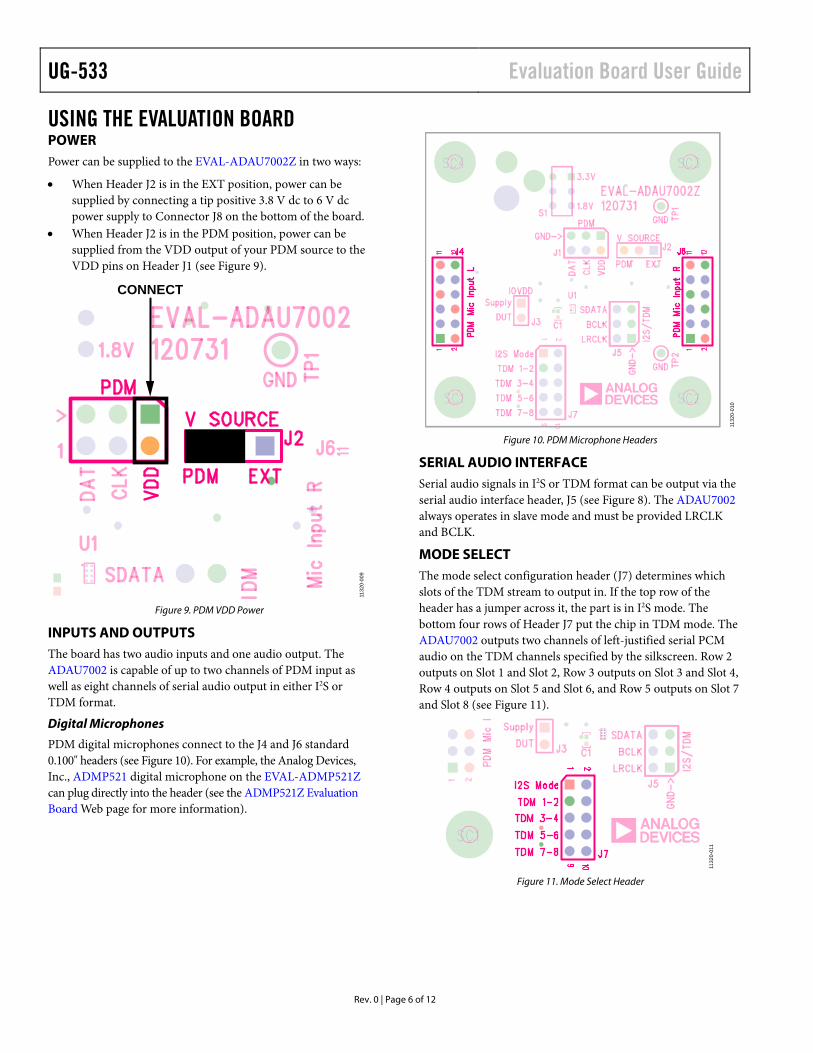
USING THE EVALUATION BOARD POWER Power can be supplied to the EVAL-ADAU7002Z in two ways:
• When Header J2 is in the EXT position, power can be supplied by connecting a tip positive 3.8 V dc to 6 V dc power supply to Connector J8 on the bottom of the board.
• When Header J2 is in the PDM position, power can be supplied from the VDD output of your PDM source to the VDD pins on Header J1 (see Figure 9).
CONNECT
1132
0-00
9
Figure 9. PDM VDD Power
INPUTS AND OUTPUTS The board has two audio inputs and one audio output. The ADAU7002 is capable of up to two channels of PDM input as well as eight channels of serial audio output in either I2S or TDM format.
Digital Microphones
PDM digital microphones connect to the J4 and J6 standard 0.100" headers (see Figure 10). For example, the Analog Devices, Inc., ADMP521 digital microphone on the EVAL-ADMP521Z can plug directly into the header (see the ADMP521Z Evaluation Board Web page for more information).
1132
0-01
0
Figure 10. PDM Microphone Headers
SERIAL AUDIO INTERFACE Serial audio signals in I2S or TDM format can be output via the serial audio interface header, J5 (see Figure 8). The ADAU7002 always operates in slave mode and must be provided LRCLK and BCLK.
MODE SELECT The mode select configuration header (J7) determines which slots of the TDM stream to output in. If the top row of the header has a jumper across it, the part is in I2S mode. The bottom four rows of Header J7 put the chip in TDM mode. The ADAU7002 outputs two channels of left-justified serial PCM audio on the TDM channels specified by the silkscreen. Row 2 outputs on Slot 1 and Slot 2, Row 3 outputs on Slot 3 and Slot 4, Row 4 outputs on Slot 5 and Slot 6, and Row 5 outputs on Slot 7 and Slot 8 (see Figure 11).
1132
0-01
1
Figure 11. Mode Select Header

Evaluation Board User Guide UG-533
Rev. 0 | Page 7 of 12
HARDWARE DESCRIPTION JUMPERS
Table 1. Connector and Jack Descriptions Reference Functional Name Description J1 PDM input Jumper used for PDM input signals and VDD source. J2 Voltage source Header used to choose powering the board from the PDM input or from the on-board regulator. J3 IOVDD Unpopulated header used for measuring IOVDD current. J4, J6 PDM microphone inputs Headers that allow digital microphones to be connected to the evaluation board. J5 I2S/TDM Jumper used for serial audio output in either I2S or TDM format. J7 Mode select Jumper used to choose between different modes of operation. See the Mode Select section. J8 Power connector Tip positive 3.8 V dc to 6 V dc power connector.
INTEGRATED CIRCUITS (IC)
Table 2. IC Descriptions Reference Functional Name Description U1 ADAU7002 PDM to I2S/TDM converter. U2 ADP3336 Adjustable output low dropout regulator.

UG-533 Evaluation Board User Guide
Rev. 0 | Page 8 of 12
EVALUATION BOARD SCHEMATICS AND ARTWORK
I2S FormatTDM Slots 1-2 UsedTDM Slots 3-4 UsedTDM Slots 5-6 UsedTDM Slots 7-8 Used
Left Mic in
Right Mic In
EVAL-ADMP521Z interfaces
1/12: GND2/11: Power3/10: PDM_CLK4/9: PDM_DAT5/8: N/C6/7: L/R Select (L=Hi, R=Lo)
One decoupling near each Mic jack.
DUT
Supply
VDD
DATCLK
PDM
A2 PDM_CLKA1 PDM_DAT
D2 CONFIG
C2LRCLKB2BCLKB1SDATA
C1GND
D1IO
VDD
U1
SSM7002BCBZ
C1
0.10uF
13579
246810
J7
HEADER_10WAY_UNSHROUD
2x5
R447k5
R547k5
J3
123456
J5HEADER_6WAY_UNSHROUD
13579
2468
1012 11
J4SOCKET_12WAY_UNSHROUD
13579
2468
1012 11
J6SOCKET_12WAY_UNSHROUD 12
3456
J1
HEADER_6WAY_UNSHROUD
C10
1.0uF
C7
1.0uF
C8
1.0uF
C11
1.0uF
R6
IOVDD
IOVDD
IOVDD_PDM
IOVDDIOVDD
IOVDD
1132
0-01
2
Figure 12. Evaluation Board Schematic
DVDD= +1.8V (shown) or +3.3 V Supply
1V8
3V3
BAJ2
C9
10uF
R3
140k
C5
0.10uF
C4
C20.10uFC310uF
2
13J8
RAPC722X
C610uF
R2147k
7 IN18 IN26 SD
4GND
1OUT1 2OUT2 3OUT3 5FBU2
ADP3336
TP2 TP1
R1
169k
S1
SPDT
D1
IOVDDIOVDD_PDM
1132
0-01
3
Figure 13. Evaluation Board Schematic—Power Supply
Evaluation Board User Guide UG-533
Rev. 0 | Page 9 of 12
1132
0-01
4
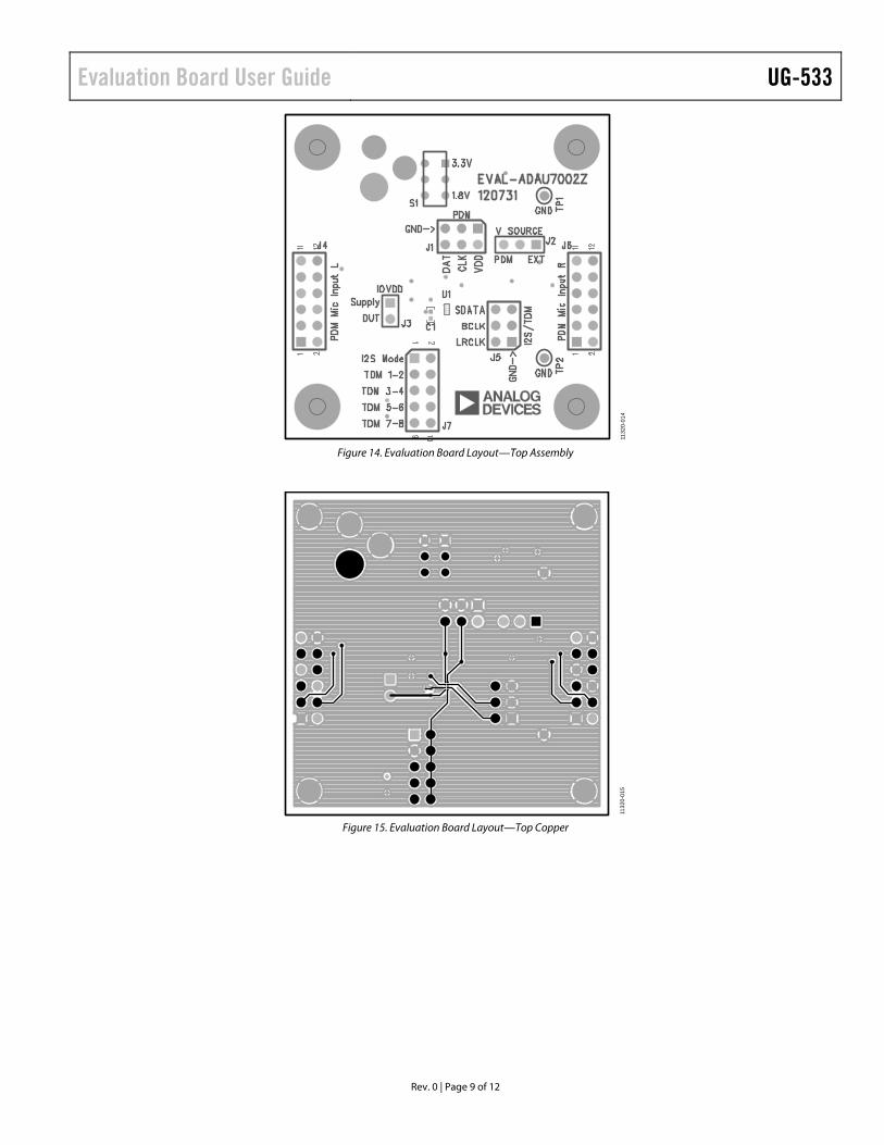
Figure 14. Evaluation Board Layout—Top Assembly
1132
0-01
5
Figure 15. Evaluation Board Layout—Top Copper
UG-533 Evaluation Board User Guide
Rev. 0 | Page 10 of 12
1132
0-01
6
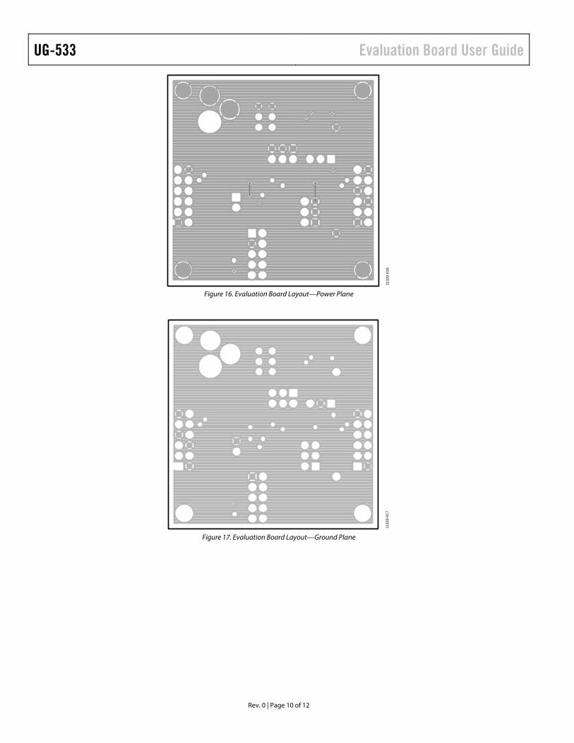
Figure 16. Evaluation Board Layout—Power Plane
1132
0-01
7
Figure 17. Evaluation Board Layout—Ground Plane
Evaluation Board User Guide UG-533
Rev. 0 | Page 11 of 12
1132
0-01
8
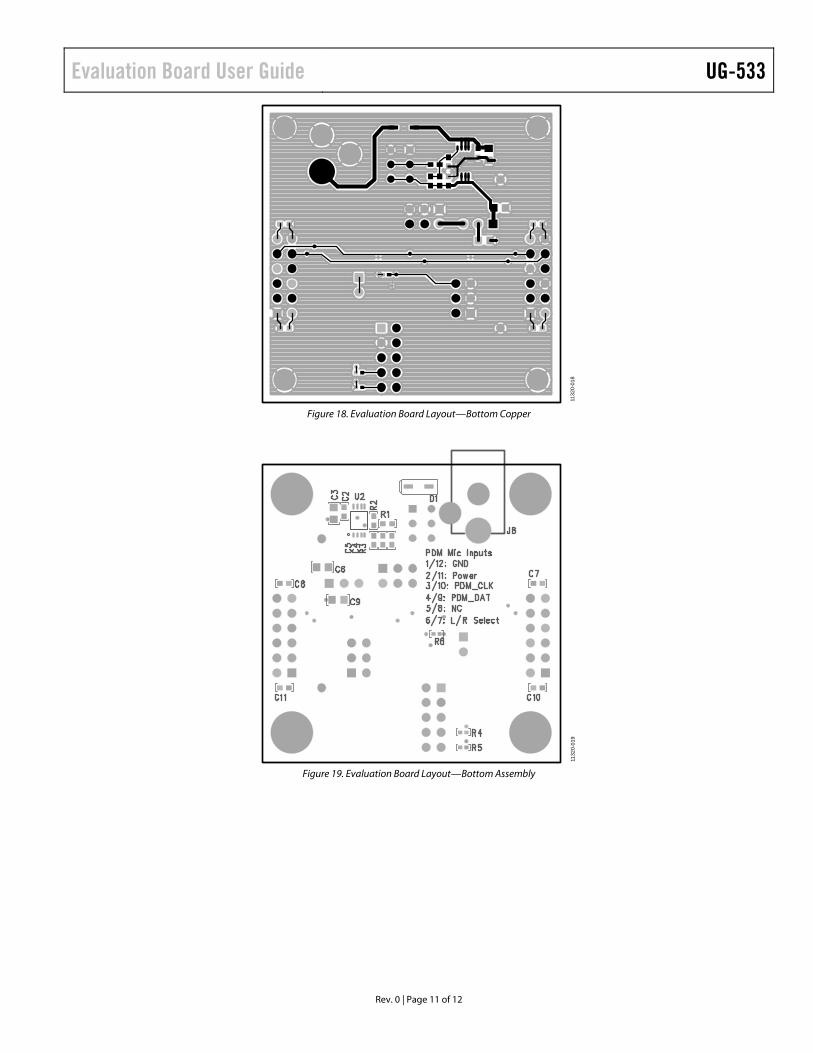
Figure 18. Evaluation Board Layout—Bottom Copper
1 132
0-01
9
Figure 19. Evaluation Board Layout—Bottom Assembly

UG-533 Evaluation Board User Guide
Rev. 0 | Page 12 of 12
BILL OF MATERIALS Table 3. Qty. Reference Value Description Part Number Manufacturer 1 C1 0.10 µF Multilayer ceramic 16 V X7R (0402) GRM155R71C104KA88D Murata ENA 2 C2, C5 0.10 µF Multilayer ceramic 50 V X7R (0603) ECJ-1VB1H104K Panasonic EC 4 C7, C8, C10, C11 1.0 µF Multilayer ceramic 16 V X7R (0603) GRM188R71C105KA12D Murata ENA 1 C4 10 nF Multilayer ceramic 25 V NP0 (0603) C1608C0G1E103J TDK Corp 3 C3, C6, C9 10 µF Multilayer ceramic 10 V X7R (0805) GRM21BR71A106KE51L Murata ENA 1 R3 140 kΩ Chip resistor 1% 100 mW thick film 0603 ERJ-3EKF1403V Panasonic EC 1 R2 147 kΩ Chip resistor 1% 100 mW thick film 0603 ERJ-3EKF1473V Panasonic EC 1 R1 169 kΩ Chip resistor 1% 100 mW thick film 0603 ERJ-3EKF1693V Panasonic EC 3 R4, R5, R6 4.75 kΩ Chip resistor 1% 63 mW thick film 0402 RMCF0402FT4K75 Stackpole 1 U1 ADAU7002BCBZ Analog Devices 1 U2 Adjustable low dropout voltage regulator ADP3336ARMZ-REEL7 Analog Devices 1 J7 10-way (2 × 5) unshrouded header PBC05DAAN, or cut PBC36DAAN 3M 2 J1, J5 6-way (2 × 3) unshrouded header PBC06DAAN, or cut PBC36DAAN 3M 1 J2 3-position SIP header PBC03SAAN, or cut PBC36SAAN Sullins 1 D1 Schottky 30 V 0.5 A SOD123 diode MBR0530T1G ON Semiconductor 1 J8 Mini power jack 0.08" R/A TH RAPC722X Switchcraft, Inc. 2 J4, J6 12-way (2 × 6) socket unshrouded PPPC062LFBN-RC 3M 1 S1 SPDT slide switch PC mount EG1271 E-Switch 2 TP1, TP2 Mini test point white 0.1" outer diameter 5002 Keystone Electronics
ESD Caution ESD (electrostatic discharge) sensitive device. Charged devices and circuit boards can discharge without detection. Although this product features patented or proprietary protection circuitry, damage may occur on devices subjected to high energy ESD. Therefore, proper ESD precautions should be taken to avoid performance degradation or loss of functionality.
Legal Terms and Conditions By using the evaluation board discussed herein (together with any tools, components documentation or support materials, the “Evaluation Board”), you are agreeing to be bound by the terms and conditions set forth below (“Agreement”) unless you have purchased the Evaluation Board, in which case the Analog Devices Standard Terms and Conditions of Sale shall govern. Do not use the Evaluation Board until you have read and agreed to the Agreement. Your use of the Evaluation Board shall signify your acceptance of the Agreement. This Agreement is made by and between you (“Customer”) and Analog Devices, Inc. (“ADI”), with its principal place of business at One Technology Way, Norwood, MA 02062, USA. Subject to the terms and conditions of the Agreement, ADI hereby grants to Customer a free, limited, personal, temporary, non-exclusive, non-sublicensable, non-transferable license to use the Evaluation Board FOR EVALUATION PURPOSES ONLY. Customer understands and agrees that the Evaluation Board is provided for the sole and exclusive purpose referenced above, and agrees not to use the Evaluation Board for any other purpose. Furthermore, the license granted is expressly made subject to the following additional limitations: Customer shall not (i) rent, lease, display, sell, transfer, assign, sublicense, or distribute the Evaluation Board; and (ii) permit any Third Party to access the Evaluation Board. As used herein, the term “Third Party” includes any entity other than ADI, Customer, their employees, affiliates and in-house consultants. The Evaluation Board is NOT sold to Customer; all rights not expressly granted herein, including ownership of the Evaluation Board, are reserved by ADI. CONFIDENTIALITY. This Agreement and the Evaluation Board shall all be considered the confidential and proprietary information of ADI. Customer may not disclose or transfer any portion of the Evaluation Board to any other party for any reason. Upon discontinuation of use of the Evaluation Board or termination of this Agreement, Customer agrees to promptly return the Evaluation Board to ADI. ADDITIONAL RESTRICTIONS. Customer may not disassemble, decompile or reverse engineer chips on the Evaluation Board. Customer shall inform ADI of any occurred damages or any modifications or alterations it makes to the Evaluation Board, including but not limited to soldering or any other activity that affects the material content of the Evaluation Board. Modifications to the Evaluation Board must comply with applicable law, including but not limited to the RoHS Directive. TERMINATION. ADI may terminate this Agreement at any time upon giving written notice to Customer. Customer agrees to return to ADI the Evaluation Board at that time. LIMITATION OF LIABILITY. THE EVALUATION BOARD PROVIDED HEREUNDER IS PROVIDED “AS IS” AND ADI MAKES NO WARRANTIES OR REPRESENTATIONS OF ANY KIND WITH RESPECT TO IT. ADI SPECIFICALLY DISCLAIMS ANY REPRESENTATIONS, ENDORSEMENTS, GUARANTEES, OR WARRANTIES, EXPRESS OR IMPLIED, RELATED TO THE EVALUATION BOARD INCLUDING, BUT NOT LIMITED TO, THE IMPLIED WARRANTY OF MERCHANTABILITY, TITLE, FITNESS FOR A PARTICULAR PURPOSE OR NONINFRINGEMENT OF INTELLECTUAL PROPERTY RIGHTS. IN NO EVENT WILL ADI AND ITS LICENSORS BE LIABLE FOR ANY INCIDENTAL, SPECIAL, INDIRECT, OR CONSEQUENTIAL DAMAGES RESULTING FROM CUSTOMER’S POSSESSION OR USE OF THE EVALUATION BOARD, INCLUDING BUT NOT LIMITED TO LOST PROFITS, DELAY COSTS, LABOR COSTS OR LOSS OF GOODWILL. ADI’S TOTAL LIABILITY FROM ANY AND ALL CAUSES SHALL BE LIMITED TO THE AMOUNT OF ONE HUNDRED US DOLLARS ($100.00). EXPORT. Customer agrees that it will not directly or indirectly export the Evaluation Board to another country, and that it will comply with all applicable United States federal laws and regulations relating to exports. GOVERNING LAW. This Agreement shall be governed by and construed in accordance with the substantive laws of the Commonwealth of Massachusetts (excluding conflict of law rules). Any legal action regarding this Agreement will be heard in the state or federal courts having jurisdiction in Suffolk County, Massachusetts, and Customer hereby submits to the personal jurisdiction and venue of such courts. The United Nations Convention on Contracts for the International Sale of Goods shall not apply to this Agreement and is expressly disclaimed.
©2013 Analog Devices, Inc. All rights reserved. Trademarks and registered trademarks are the property of their respective owners. UG11320-0-2/13(0)