Embed Size (px)
Citation preview

International Journal of Scientific & Engineering Research Volume 10, Issue 1, January-2019ISSN 2229-5518
IJSER © 2019http://www.ijser.org
Evaluation and Development of the AvailableMethods of Predicting Capacities of Driven Piles
Embedded in Basra SoilDr. Haider S. Al-Jubair, Dr. Mushtaq R. Daham
Abstract—The ultimate capacities of single piles utilized in ten projects in Basra-Iraq are evaluated using: various interpretations of pileload test results; several static methods based on site investigation programs; wave equation via (GRLWEAP) and the finite element methodvia (PLAXIS-3D). For the well-behaved tests, it is realized that the load-settlement data can be best fitted by a hyperbola. Accordingly,Rollberg method well-harmonizes the test results and allows various interpretation methods to be applied on the extrapolated curves. It isfound that, the static methods spread over a wide range of values. With a safety factor of (2.8), the allowable capacities of driven piles areestimated properly via the wave equation. Finite element analyses exhibited good agreement to the measured values. It produces failureloads, almost, similar to that obtained from Rollberg method. The finite element analyses revealed local settlement of (2% - 3.3%) of the pilesection width to mobilize the ultimate skin resistance. The necessary pile-head settlement for producing the ultimate frictional pointresistance is (13% - 22.4%) of the pile section width. Graphical relationships are suggested to obtain the adhesion and friction factors, deducedfrom the finite element method. Utilizing those relations to predict the skin resistance component with Meyerhof's (1976) method to calculatethe bearing component, gives suitable allowable capacities by applying a safety factor of (5). The maximum related settlement is (5.5 mm)which is equivalent to (0.6%) of the pile section width and is tolerable for most types of structures.
Index Terms— Driven piles, Ultimate capacity, Static approach, Wave equation, skin resistance, point bearing, Finite element—————————— u ——————————
2 INTRODUCTIONSILE foundations are widely used in Basra city due to thepresence of a shallow saturated soft cohesive soil layer ofvariable thickness in soil profile.
In order to provide the geotechnical engineers with reliableestimates to the ultimate compressive capacity of verticalpiles driven in Basra soil, the following tasks areaccomplished:1. The available equations derived based on the static
approach are evaluated to select / modify the mostadequate ones.
2. The dynamic wave equation method is evaluated.3. The methods of interpreting the static pile load test
data are assessed to indicate the most favorable ones.4. The soil-pile interaction behavior is investigated via the
finite element models.The area covered by the study is located within theadministrative, commercial, and residential center of Basracity. Ten projects utilizing driven pile foundations areconsidered as case studies for the verified methods Figure(1). The provided data sets from those projects include:geotechnical investigation reports; driving records; and loadtest data, for trial and/or working piles.
2 STATIC APPROACH For a pile of (n) segments and/or penetrating a soil profileof (n) sublayers, the ultimate compressive capacity can beexpressed as [4] and [5]:
Q = Q + Q = q ∗ A + ∑ q ∗ AWhere:Qu: ultimate load capacityQp: ultimate point capacityQs: ultimate skin resistanceqp: unit point resistanceAp: area of the pile pointqsi: unit shaft resistance within the segment or sublayer (i)Asi: corresponding surface area
The point resistance per unit area is usually calculated as:
P
Fig. 1. Locations of the projects taken into consideration
897

International Journal of Scientific & Engineering Research Volume 10, Issue 1, January-2019ISSN 2229-5518
IJSER © 2019http://www.ijser.org
= +
Where: , : bearing capacity factors adjusted for depth and
shape.: effective overburden pressure at pile point.
c : soil cohesion around pile point.φ: soil angle of internal friction.
The (N'c) factor could be predicted using the formula [12]:N'c = 6 + ≤ 9
Whereas the (N'q) factor can be obtained from Figure (2). Theunit point resistance can also be predicted based on thestandard penetration number as [2]:
= 40 ≤ 400
The unit skin resistance can be predicted using the followinggeneral equation:
= α + tan = α +
Where:α: adhesion factor.
: effective overburden pressure at the mid-depth ofpenetration in soil layer.
K: lateral earth pressure coefficient.: friction angle between the soil and pile material.φ: soil angle of internal friction.
The values or formulas for estimating the necessaryparameters, suggested by different authors are summarizedin Table (1). The unit skin resistance can also be predicted
based on the standard penetration number as [5]:= 2
or [3]:= (4 5)
TABLE 1SUMMARY OF THE SKIN RESISTANCE PARAMETERS
3 WAVE EQUATION The wave equation analysis is based on the theory ofpropagation of the linear waves (Figure 3). In this approach,the pile behavior during driving is modelled, considering
Fig. 2. ( ′ ) values vs the angle of internal friction, [12].
898

International Journal of Scientific & Engineering Research Volume 10, Issue 1, January-2019ISSN 2229-5518
IJSER © 2019http://www.ijser.org
factors such as driving energy delivered to the pile at impact,propagation of compressive and tensile waves, soil staticresistance along the pile shaft and resistance below the piletoe, as well as dynamic behavior of soil as a viscous body.The basic wave equations for pile driving analysis are [14]:
( , ) = ( , − 1) + ( , − 1)( , ) = ( , )− ( + 1, )( , ) = ( , ) + ( )
( , ) = ( , − 1) + [ ( − 1, ) + W(m)− F(m, t)−R(m, t)]
( )
With no damping:( , ) = [ ( , )− ( , )] ( )[1 + ( ) ( , − 1)]
With damping:( , ) = ( )
( , ) = [ ( , )− ( , )] ( )+ ( ) ( ) ( , − 1)]
Where:m: element numbert: timeg: acceleration caused by gravity
( ): spring constant for internal spring m( ): weight of the element m
( , ): velocity of element m at time t( , ): displacement of element m at time t′( , ): plastic displacement of external spring (i.e. the
surrounding ground)m at time t
( , ): force exerted by external spring m on element m attime t
( ): dynamic resistance of element m( ): soil-damping constant at element mΔt: time interval considered
( , ): compression of internal spring m at time t
′( ): spring constant for external spring m( , ): force in internal spring at time t( , − 1): velocity of element at time t-1( , − 1): displacement of element m at time t-1′( ): quake for external spring m (or maximum
elastic soil deformation)( ): ultimate static resistance of external soil spring m
A licensed package of the latest version of GRLWEAP fromPDI [6] is utilized for the present research.
4 PILE LOAD TESTS The most common test procedure in Iraq is the slow
maintained load test according to the ASTM-D1143 [1]. Thetrue failure occurs when the pile plunges down into theground without any further increase in load [12] but, manysettlement-based failure criteria have been defined. Otherinterpretation methods have been developed like [9], [11]:Davisson; Chin; Hansen (80% and 90%); Dee-Beer; Fullerand Hoy; Butler and Hoy; Van der Veen; and Rollbergmethods.
Fig. 3. Wave equation analysis [14]
899

International Journal of Scientific & Engineering Research Volume 10, Issue 1, January-2019ISSN 2229-5518
IJSER © 2019http://www.ijser.org
5 FINITE ELEMENT METHOD For the three-dimensional stress analysis, the matrixequations are [10]:
=
Where:=global stiffness matrix
=global vector of nodal displacements = global nodal load vector
= ∑ [ ( )]
= +∑ ( )+∑ ( )
+∑ ( )
[ ( )] = ∭ [ ]( ) [ ][ ]
( )= ∭ [ ]( ) [ ] ° = element load vector due
to initial strain ( )
= ∬ [ ]( ) Φ = element load vector dueto surface forces
( )= ∭ [ ]( ) ∅ = element load vector due
to body forces[ ( )] = element stiffness matrix = vector of concentrated loads
= the volume of the bodyn = number of elements[ ] = shape function = vector of initial strains
= the surface of the body
A time limited license of PLAXIS-3D Foundation (2015) isused in the current study. The soil is modeled using Mohr-Coulomb criterion whereas, a linear elastic model is selectedto represent pile material. In order to reduce the effect ofboundaries on the results, the soil media are extended tominimum distances of ten times pile width from the pileedge in the lateral directions, and five times pile width belowthe pile tip [4]. Soil properties are drawn from thegeotechnical investigation reports and some parameters arespecified based on correlative relations in case of lack of data[15-34].
6 DISCUSSION TO THE RESULTS All the input data and output results are presented for thefirst project only. For the remaining nine projects, partialinputs / outputs are presented in the summary Tables. Thefirst project is a multistory surgical complex buildingsupported on (400mm x 400mm x 24m) precast concretepiles, driven via a diesel hammer (Delmag D22) into the soilprofile shown in Figure (4) [15]. The measured load-
settlement curve is shown in Figure (5) [16]. The ultimateload capacities obtained from the various interpretationmethods are shown in Figures (6) through (11). It is realized that a test load of (2700 kN), which isequivalent to (300%) the design load, could not bring the pileto plunging. The ultimate loads obtained by Davisson’smethod (2330.0 kN) and according to a net settlement of (0.25in = 6.35 mm) (2560.0 kN), are within the range of test load.Other methods revealed values exceeded that load, such asChin’s (3225.0 kN), Brinch Hansen's 80% (2887.0 kN), andVan der Veen's (2750.0 kN) methods. Rollberg method has the ability to extrapolate the load-settlement curve beyond the maximum test load to theplunging limit. This provides the possibility to examinemany settlement-based failure criteria. Accordingly, theultimate capacities based on pre-assigned pile-buttsettlement values equivalent to [(6% B), (Elastic + B/30), (10%B) and (20% B)] are [(2595.0 kN), (2693.0 kN), (2807.0 kN) and(3230.0 kN)], respectively.
Fig. 4. Soil-pile profile (project No. 1)
900

International Journal of Scientific & Engineering Research Volume 10, Issue 1, January-2019ISSN 2229-5518
IJSER © 2019http://www.ijser.org
-settlement curve is shown in Figure (5) [16]. The ultimateload capacities obtained from the various interpretationmethods are shown in Figures (6) through (11). It is realized that a test load of (2700 kN), which isequivalent to (300%) the design load, could not bring the pileto plunging. The ultimate loads obtained by Davisson’smethod (2330.0 kN) and according to a net settlement of (0.25in = 6.35 mm) (2560.0 kN), are within the range of test load.Other methods revealed values exceeded that load, such asChin’s (3225.0 kN), Brinch Hansen's 80% (2887.0 kN), andVan der Veen's (2750.0 kN) methods. Rollberg method has the ability to extrapolate the load-settlement curve beyond the maximum test load to theplunging limit. This provides the possibility to examinemany settlement-based failure criteria. Accordingly, theultimate capacities based on pre-assigned pile-buttsettlement values equivalent to [(6% B), (Elastic + B/30), (10%B) and (20% B)] are [(2595.0 kN), (2693.0 kN), (2807.0 kN) and(3230.0 kN)], respectively. It is clear that, the Chin’s capacity is very close to theplunging load, as calculated via Rollberg extrapolated curveat a settlement of (80 mm = 20% B). The ultimate VanderVeen’s and Brinch Hansen's 80% capacities are very close tothe Rollberg's value associated with a settlement of (40 mm= 10% B).
Fig. 5. Ultimate pile capacity by Davisson’s method (project No. 1)
Fig. 6. Ultimate pile capacity by Davisson’s method
(project No. 1)
Fig. 7. Ultimate pile capacity by Chin’s method(project No. 1).
901

International Journal of Scientific & Engineering Research Volume 10, Issue 1, January-2019ISSN 2229-5518
IJSER © 2019http://www.ijser.org
Fig. 8. Ultimate pile capacity by Brinch Hansen’s 80%method (project No. 1).
Fig. 9. Ultimate pile capacity by Vander-Veen’s method(project No. 1)
Fig. 10. Ultimate pile capacity based on net-settlementcriterion (project No. 1).
Fig. 11. Ultimate pile capacity by Rollberg’s method(project No. 1).
902

International Journal of Scientific & Engineering Research Volume 10, Issue 1, January-2019ISSN 2229-5518
IJSER © 2019http://www.ijser.org
The ultimate capacities, produced by Davisson’s methodand the net settlement criterion, are the most conservativeamong the values obtained from the applicable methods.The range of test load and the produced slopes renderedBrinch Hansen's 90%, De Beer’s, Fuller & Hoy’s and Butler& Hoy’s methods inapplicable for this project. The existence of numerous static methods for skin andpoint resistances estimation produce a big number ofcombinations for pile capacities. The maximum andminimum capacities are summarized in Table (2).
TABLE 2Ultimate extremum values by the static methods
(project No. 1).
The minimum ultimate static load underestimatesthe true capacity whereas, the maximum value is very closeto its load-test counterpart, obtained from the (16% B)settlement criterion. The skin resistance component rangesfrom (970.4 kN) to (1243.4 kN) while, the point bearingcomponent ranges from (216.0 kN) to (1836.3 kN). These twocomponents shall be further discussed after the presentationof the finite element results.
The results of the wave equation shown in Figure (12)gives an ultimate capacity of (3100.0 kN), which is close tothe plunging load, with a skin resistance of about (43% Qu=1333 kN) and a point bearing of (57% Qu =1767 kN). It isalso shown that, the pile driving induced compressivestresses in the pile material reached (36.75 MPa), whichexceeds the recommended allowable value [2] of (0.85 =34.0 MPa). This gives an indication of overdriving (very lowset value).
The input parameters for the finite element analysisare listed in Table (3). The finite element mesh is shown inFigure (13) whereas, the displacement contours aredemonstrated in Figure (14) for a sample load. The predicted
behavior is compared to the measured one in Figure (15)whereas, the computed load-settlement curves for thedifferent resistance components are shown in Figure (16).The analysis is terminated at an ultimate load of (3157.9 kN).
Figure (17) illustrate the load transferred from pileto soil, whereas the variations of pile displacement withdepth are illustrated in Figure (18), for various multiples ofthe design load. It is realized that at the design load, the pointbearing has no contribution in load resistance which isrestricted to the skin component, which is fully mobilized ata butt settlement of around (11mm = 2.8% B) or localdisplacement around (9mm = 2.3% B), and an applied loadof (250% Qdesign). The point bearing component continues toincrease and reaching its maximum value at a buttsettlement of around (89 mm = 22.2% B), which is associatedwith plunging. The contributions of soil layers in skin resistance arecalculated from the load differences at layer boundaries. Theresults are listed in Table (4). According to the transferredforce within each layer and the associated pile surface area,the skin resistance parameters (αi and ) are back calculatedfor the static method, from the finite element results, as:
uii
ii
cAsQs
´=a
sdb
¢´==
44
4tan.oavAs
QsK
and the results are listed in Table (5). Adhesion factors of(1.04) for medium stiff clay is uncommon value, whereas,values of (1.23) and (1.14) for soft clayey layers of cohesion(19kN/m2) and (25kN/m2), respectively are frequent. Inaddition to that, the predicted -value gives high unit shearstress within the cohesionless layer that exceeds the limit of(100 kPa), which is recommended by many references.
Conclusions For the studied ten projects, the following conclusions canbe drawn:1. Pile load tests in Basrah are usually used as proof tests,even for the trial piles. Piles are rarely tested to failure.2. For a well-conducted tests (with no problems), the load-
settlement data can be fitted with a considerable degreeof accuracy by a hyperbola. According to that, Rollbergmethod simulates the test results in a good manner andpermits the application of many interpretation criteria onthe extrapolated curves.
903

International Journal of Scientific & Engineering Research Volume 10, Issue 1, January-2019ISSN 2229-5518
IJSER © 2019http://www.ijser.org
Fig. 12. Ultimate pile capacity by the wave equation (project No. 1)
904

International Journal of Scientific & Engineering Research Volume 10, Issue 1, January-2019ISSN 2229-5518
IJSER © 2019http://www.ijser.org
TABLE 3Input parameters of Finite element analysis (project No. 1).
Fig. 13. Finite element mesh (project 1)Fig. 14. Displacement contours at an applied load of
(1700.0 kN) (project No. 1). [12].
905

International Journal of Scientific & Engineering Research Volume 10, Issue 1, January-2019ISSN 2229-5518
IJSER © 2019http://www.ijser.org
Fig. 15. Predicted load-settlement curve vs measuredone (project No. 1).
Fig. 16. Predicted ultimate capacities (project No. 1).
Fig. 17. Load transfer vs depth (project No. 1)
Fig. 18. Pile displacement versus depth (project No. 1)
906

International Journal of Scientific & Engineering Research Volume 10, Issue 1, January-2019ISSN 2229-5518
IJSER © 2019http://www.ijser.org
TABLE 4Contributions of soil layers in load resistance (project No. 1)
TABLE 5Predicted skin resistance parameters (project No. 1).
TABLE 6Summary of the interpretations, static, and dynamic methods
907
International Journal of Scientific & Engineering Research Volume 10, Issue 1, January-2019ISSN 2229-5518
IJSER © 2019http://www.ijser.org
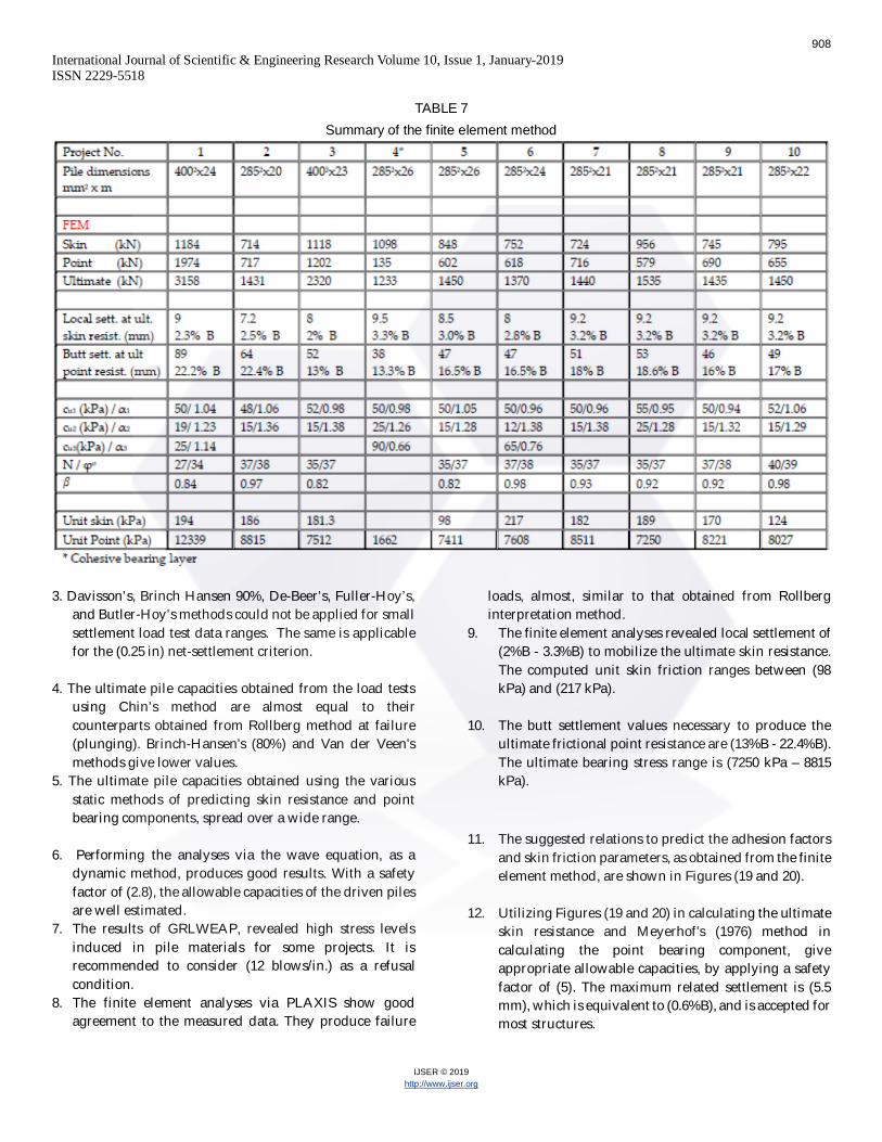
TABLE 7Summary of the finite element method
3. Davisson’s, Brinch Hansen 90%, De-Beer’s, Fuller-Hoy’s,and Butler-Hoy’s methods could not be applied for smallsettlement load test data ranges. The same is applicablefor the (0.25 in) net-settlement criterion.
4. The ultimate pile capacities obtained from the load testsusing Chin’s method are almost equal to theircounterparts obtained from Rollberg method at failure(plunging). Brinch-Hansen's (80%) and Van der Veen'smethods give lower values.
5. The ultimate pile capacities obtained using the variousstatic methods of predicting skin resistance and pointbearing components, spread over a wide range.
6. Performing the analyses via the wave equation, as adynamic method, produces good results. With a safetyfactor of (2.8), the allowable capacities of the driven pilesare well estimated.
7. The results of GRLWEAP, revealed high stress levelsinduced in pile materials for some projects. It isrecommended to consider (12 blows/in.) as a refusalcondition.
8. The finite element analyses via PLAXIS show goodagreement to the measured data. They produce failure
loads, almost, similar to that obtained from Rollberginterpretation method.
9. The finite element analyses revealed local settlement of(2%B - 3.3%B) to mobilize the ultimate skin resistance.The computed unit skin friction ranges between (98kPa) and (217 kPa).
10. The butt settlement values necessary to produce theultimate frictional point resistance are (13%B - 22.4%B).The ultimate bearing stress range is (7250 kPa – 8815kPa).
11. The suggested relations to predict the adhesion factorsand skin friction parameters, as obtained from the finiteelement method, are shown in Figures (19 and 20).
12. Utilizing Figures (19 and 20) in calculating the ultimateskin resistance and Meyerhof's (1976) method incalculating the point bearing component, giveappropriate allowable capacities, by applying a safetyfactor of (5). The maximum related settlement is (5.5mm), which is equivalent to (0.6%B), and is accepted formost structures.
908

International Journal of Scientific & Engineering Research Volume 10, Issue 1, January-2019ISSN 2229-5518
IJSER © 2019http://www.ijser.org
References[1]. ASTM D1143/ D1143M, (2013), “Standard Test
Methods for Deep Foundations Under Static AxialCompressive Load”, 11 pp.
[2]. Bowles, J. (1997), “Foundation Analysis andDesign-5th ed.”, The McGraw-Hill CompaniesCorp, New York, St. Louise, 1168 pp.
[3]. Caltrans A. D. (2015), “Foundation Manual-2nd
ed.”, California Department of Transport, 522 pp.[4]. Fleming, K. and Weltman, A. (2009), “Piling
Engineering-3rd ed.” ,Taylor and Francis Group,London and New York, 407 pp.
[5]. Gunaratne, Manjriker (2006), “The FoundationEngineering Handbook-st ed.”, Tayler & FrancisGroup, Boca Raton, London and New York, 625 pp.
[6]. GRLWEAP (2010), “Theoretical BackgroundManual”, 155 pp.
[7]. PLAXIS 3D Foundation (2015), "Scientific manual", 66 pp.
[8]. Poulos H. and Davis E. (1980), “Pile FoundationAnalysis and Design-1st ed.”, Rainbow Bridge Co.Canada, 410 pp.
[9]. Prakash, S. and Sharma, H. (1990), “PileFoundations in Engineering Practice-1st ed.”, JohnWiley & Sons, Inc. New York Chichester, 759 pp.
[10]. Rao, S.S. (2004),“Finite Element Method inEngineering-4th ed.”, USA: Elsevier Science &Technology Books, 747 pp.
[11]. SHROF, A. AND SHAH D. (2003), “SOIL
MECHANICS AND GEOTECHNICAL ENGINEERING-1ST
ED.”, A. A. BALKEMA PUPLISHERS. LISSE, ABINGDON,EXTON, TOKYO, 463 PP.
[12]. Tomlinson, M. and Woodward, J. (2015),“Pile Design and Construction Practice-6th ed.”,Taylor and Francis Group, London and New York,597 pp.
[13]. Viggiani, C. and Mandolini, M. (2012),“Piles and Pile Foundations-1st ed.”, Spon Press,London and New York, 229 pp.
[14]. W.W. Li, and M. L. Cheng. (2006).“Foundation Design and Construction-1st ed.”, TheGovernment of the Hong Kong SpecialAdministrative Region, first edition, 376 pp.
Site investigation and pile load test reports
[15]. University of Basra, EngineeringConsulting Bureau, (March, 2008), “SoilInvestigation Report, Kuwaiti Surgical ComplexHospital”, (No. 1-SI-2008).
[16]. Al Fao Company for Geotechnical and SoilInvestigation (March, 2013), “Pile Static Load TestReport, Kuwaiti Surgical Complex Hospital”, (No.511).
[17]. Andrea Engineering Test Laboratories(Nov, 2004), “Soil Investigation Report, BasraChildren’s Hospital”, (No. 1051R).
[18]. Andrea Engineering Test Laboratories(Aug, 2005), “Pile Static Load Test, BasraChildren’s Hospital”, (No. 511).
[19]. National Center for Construction Labs,(May, 2011), “Soil Investigation Report, Al-Mina’aStadium”, (No. 2-1-43).
Fig. 19. Adhesion factors for driven piles in Basrah soil
Fig. 20. Skin friction factor vs. standard penetrationnumber for driven piles in Basrah soil
909

International Journal of Scientific & Engineering Research Volume 10, Issue 1, January-2019ISSN 2229-5518
IJSER © 2019http://www.ijser.org
[20]. Al-Tariq Engineering Bureau, (Feb, 2012),“Pile Static Load Test, Al-Mina’a Stadium”, (No.409).
[21]. University of Basra, EngineeringConsulting Bureau, (May, 2013), “SoilInvestigation Report,Shatt-Al Arab Central WaterTreatment Plant”, (No. 19/SI/2013).
[22]. Al-Meazan Co for Pile Test, (Aug, 2013),“Pile Static Load Test, Shatt-Al Arab CentralWater Treatment Plant”, (No. 95).
[23]. University of Basra, EngineeringConsulting Bureau, (May, 2008), “SoilInvestigation Report,Al Basra West ElectricalSubstation (132 kV)”, (No.6/SI/2008).
[24]. National Engineering Contracts, (Jan,2010), “Pile Static Load Test, Al Basra WestElectrical Substation (132 kV)”, (No. Jan-2010).
[25]. National Center for Construction Labs,(Aug, 2013), “Soil Investigation Report,Shatt AlArab Hospital”, (No. 2-1-44).
[26]. Al-Liqa’a Engineering Bureau, (Jan, 2013),“Pile Static Load Test, Shatt Al Arab Hospital”,(No. 364).
[27]. National Center for Construction Labs,(June, 2011), “Soil Investigation Report,HealthCare Center”, (No. 2-1-43).
910