Embed Size (px)
Citation preview

IT 11 008
Examensarbete 30 hpFebruary 2011
Evaluation and Enhancement of TCP with Network Coding in Wireless Multihop Networks
Xiaolin Bai
Institutionen för informationsteknologiDepartment of Information Technology


Teknisk- naturvetenskaplig fakultet UTH-enheten Besöksadress: Ångströmlaboratoriet Lägerhyddsvägen 1 Hus 4, Plan 0 Postadress: Box 536 751 21 Uppsala Telefon: 018 – 471 30 03 Telefax: 018 – 471 30 00 Hemsida: http://www.teknat.uu.se/student
Abstract
Evaluation and Enhancement of TCP with NetworkCoding in Wireless Multihop Networks
Xiaolin Bai
Network coding is a very promising technology to efficiently utilize resources of bothwired and wireless networks, and has received much attention from both academiaand industry recently. Since wireless channel is inherently broadcast and suitable forapplication of network coding. However, the performance of legacy TCP overwireless ad hoc network is not satisfactory due to the special features of wirelessnetworks, such as hidden terminal and exposed terminal problems, transmissionerrors, topology variations and routing instability, etc. As we know, the performancedegradation of TCP may be caused by the rate control mechanism of TCP itself androuting protocol, while no research on this issue has been found until now. Thus, inthis paper, we implement the COPE based on NS-2, and evaluate the performance ofCOPE with other TCP protocols adapted for wireless ad hoc network, such asTCP-FeW and TCP-AP. The simulation results show that COPE can greatly improvethe network throughput and is reasonable framework to wireless network coding.However, COPE does not work for every network topology with each TCP protocol,or even worse than the traditional transmission mode. To overcome this problem, Ipropose two schemes to improve the performance of TCP over wireless networkcoding. One is called Encode Once, which ensures the packet being encoded at mostone time and improves the performance of COPE. Another one is called NetworkCoding Aware TCP, which adapts sending rate of TCP based onTCP-AP protocol and increases the network throughput.
Tryckt av: Reprocentralen ITCIT 11 008Examinator: Anders JanssonÄmnesgranskare: Ping WuHandledare: Lianghui Ding


Contents
1 Introduction 81.1 Problem Statement and Motivation . . . . . . . . . . . . . . . . . . .. . . . . . . . . . 81.2 Contributions . . . . . . . . . . . . . . . . . . . . . . . . . . . . . . . . . . .. . . . . 91.3 Thesis Structure . . . . . . . . . . . . . . . . . . . . . . . . . . . . . . . . .. . . . . . 9
2 Wireless Multihop Networks and Network Coding 102.1 Wireless Ad Hoc Networks . . . . . . . . . . . . . . . . . . . . . . . . . . .. . . . . . 102.2 TCP in Wireless Ad Hoc Networks . . . . . . . . . . . . . . . . . . . . . .. . . . . . . 10
2.2.1 NewReno . . . . . . . . . . . . . . . . . . . . . . . . . . . . . . . . . . . . . . 122.2.2 TCP-FeW . . . . . . . . . . . . . . . . . . . . . . . . . . . . . . . . . . . . . . 122.2.3 TCP-AP . . . . . . . . . . . . . . . . . . . . . . . . . . . . . . . . . . . . . . . 12
2.3 Network Coding . . . . . . . . . . . . . . . . . . . . . . . . . . . . . . . . . . .. . . . 132.4 COPE . . . . . . . . . . . . . . . . . . . . . . . . . . . . . . . . . . . . . . . . . . . .14
2.4.1 Opportunistic Listening . . . . . . . . . . . . . . . . . . . . . . . .. . . . . . 152.4.2 Opportunistic Coding . . . . . . . . . . . . . . . . . . . . . . . . . . .. . . . . 152.4.3 Reception Report . . . . . . . . . . . . . . . . . . . . . . . . . . . . . . .. . . 15
3 Network Simulator: NS-2 16
4 Implementation of COPE on NS-2 204.1 Opportunistic Listening . . . . . . . . . . . . . . . . . . . . . . . . . .. . . . . . . . . 204.2 Opportunistic Coding . . . . . . . . . . . . . . . . . . . . . . . . . . . . .. . . . . . . 204.3 Reception Report . . . . . . . . . . . . . . . . . . . . . . . . . . . . . . . . .. . . . . 214.4 Pseudo Broadcast . . . . . . . . . . . . . . . . . . . . . . . . . . . . . . . . .. . . . . 214.5 Asynchronous ACK and Retransmission . . . . . . . . . . . . . . . .. . . . . . . . . . 214.6 Packet Reception . . . . . . . . . . . . . . . . . . . . . . . . . . . . . . . . .. . . . . 214.7 Definition of Packet Header . . . . . . . . . . . . . . . . . . . . . . . . .. . . . . . . . 224.8 Definition of COPE . . . . . . . . . . . . . . . . . . . . . . . . . . . . . . . . .. . . . 224.9 Definition of Queues . . . . . . . . . . . . . . . . . . . . . . . . . . . . . . .. . . . . 23
4.9.1 COPEPriQueue . . . . . . . . . . . . . . . . . . . . . . . . . . . . . . . . . .. 234.9.2 NonAckQueue . . . . . . . . . . . . . . . . . . . . . . . . . . . . . . . . . . .244.9.3 AckPendQueue . . . . . . . . . . . . . . . . . . . . . . . . . . . . . . . . . .. 254.9.4 PacketPool . . . . . . . . . . . . . . . . . . . . . . . . . . . . . . . . . . . .. 254.9.5 PacketInfo . . . . . . . . . . . . . . . . . . . . . . . . . . . . . . . . . . . .. 274.9.6 ProbGuess . . . . . . . . . . . . . . . . . . . . . . . . . . . . . . . . . . . . .274.9.7 VirQueue . . . . . . . . . . . . . . . . . . . . . . . . . . . . . . . . . . . . . .30
4.10 Timers . . . . . . . . . . . . . . . . . . . . . . . . . . . . . . . . . . . . . . . . .. . . 304.10.1 CopeTimer . . . . . . . . . . . . . . . . . . . . . . . . . . . . . . . . . . . .. 30
5

4.10.2 NonAckTimer . . . . . . . . . . . . . . . . . . . . . . . . . . . . . . . . . .. 314.10.3 CtrlPktTimer . . . . . . . . . . . . . . . . . . . . . . . . . . . . . . . . .. . . 31
4.11 Opportunistic Listening . . . . . . . . . . . . . . . . . . . . . . . . .. . . . . . . . . . 314.12 Opportunistic Coding . . . . . . . . . . . . . . . . . . . . . . . . . . . .. . . . . . . . 314.13 Decoding . . . . . . . . . . . . . . . . . . . . . . . . . . . . . . . . . . . . . . .. . . 344.14 Reception Report . . . . . . . . . . . . . . . . . . . . . . . . . . . . . . . .. . . . . . 354.15 Asynchronous ACKs . . . . . . . . . . . . . . . . . . . . . . . . . . . . . . .. . . . . 354.16 Control Packet . . . . . . . . . . . . . . . . . . . . . . . . . . . . . . . . . .. . . . . . 354.17 Retransmission . . . . . . . . . . . . . . . . . . . . . . . . . . . . . . . . .. . . . . . 354.18 Resume a packet . . . . . . . . . . . . . . . . . . . . . . . . . . . . . . . . . .. . . . 364.19 TCP Reordering . . . . . . . . . . . . . . . . . . . . . . . . . . . . . . . . . .. . . . . 36
5 Simulation and Performance 375.1 Simulation Setup . . . . . . . . . . . . . . . . . . . . . . . . . . . . . . . . .. . . . . 375.2 Performance Metrics . . . . . . . . . . . . . . . . . . . . . . . . . . . . . .. . . . . . 375.3 Simulation Results . . . . . . . . . . . . . . . . . . . . . . . . . . . . . . .. . . . . . 38
5.3.1 Chain Topology . . . . . . . . . . . . . . . . . . . . . . . . . . . . . . . . .. . 385.3.2 X-I Topology . . . . . . . . . . . . . . . . . . . . . . . . . . . . . . . . . . .. 385.3.3 X-II Topology . . . . . . . . . . . . . . . . . . . . . . . . . . . . . . . . . .. 39
6 Proposal and Evaluation 426.1 Encode Once . . . . . . . . . . . . . . . . . . . . . . . . . . . . . . . . . . . . . .. . 426.2 Network Coding Aware TCP . . . . . . . . . . . . . . . . . . . . . . . . . . .. . . . . 43
7 Conclusions and Future Work 457.1 Conclusions . . . . . . . . . . . . . . . . . . . . . . . . . . . . . . . . . . . . .. . . . 457.2 Future Work . . . . . . . . . . . . . . . . . . . . . . . . . . . . . . . . . . . . . .. . . 45
Bibliography 47
6

List of Figures
2.1 A Classic Wireless Ad Hoc Network . . . . . . . . . . . . . . . . . . . .. . . . . . . . 112.2 Principle of Network Coding . . . . . . . . . . . . . . . . . . . . . . . .. . . . . . . . 132.3 COPE Example . . . . . . . . . . . . . . . . . . . . . . . . . . . . . . . . . . . . .. . 14
3.1 Structure of mobile node in NS-2 . . . . . . . . . . . . . . . . . . . . .. . . . . . . . . 173.2 Structure of mobile node with COPE in NS-2 . . . . . . . . . . . . .. . . . . . . . . . 19
4.1 COPE Packet Header . . . . . . . . . . . . . . . . . . . . . . . . . . . . . . . .. . . . 224.2 COPE Structure . . . . . . . . . . . . . . . . . . . . . . . . . . . . . . . . . . .. . . . 234.3 Class Graph for COPEPriQueue . . . . . . . . . . . . . . . . . . . . . . .. . . . . . . 244.4 Butterfly Topology . . . . . . . . . . . . . . . . . . . . . . . . . . . . . . . .. . . . . 284.5 Neighbors’ Packet Status . . . . . . . . . . . . . . . . . . . . . . . . . .. . . . . . . . 284.6 Downside Packet Received . . . . . . . . . . . . . . . . . . . . . . . . . .. . . . . . . 324.7 Upside Packet Received . . . . . . . . . . . . . . . . . . . . . . . . . . . .. . . . . . . 34
5.1 Chain Topology . . . . . . . . . . . . . . . . . . . . . . . . . . . . . . . . . . .. . . . 385.2 Throughput in Chain Topology . . . . . . . . . . . . . . . . . . . . . . .. . . . . . . . 395.3 X-I Topology . . . . . . . . . . . . . . . . . . . . . . . . . . . . . . . . . . . . .. . . 405.4 Throughput in X-I Topology . . . . . . . . . . . . . . . . . . . . . . . . .. . . . . . . 405.5 X-II Topology . . . . . . . . . . . . . . . . . . . . . . . . . . . . . . . . . . . .. . . . 415.6 Throughput in X-II Topology . . . . . . . . . . . . . . . . . . . . . . . .. . . . . . . . 41
6.1 Throughput of X-I topology with Encode Once . . . . . . . . . . .. . . . . . . . . . . 436.2 Throughput of X-I topology with Network Coding Aware Using TCP-AP . . . . . . . . 44
7

Chapter 1
Introduction
Network coding, is young and very promising technology. It was the seminal paper “Network informationflow” by Ahlswede, Cai, Li and Yeung [1], that gave “birth” to network coding. Network coding is toefficiently utilize resources in both wired and wireless networks, by letting the routers operate on thepackets rather than pure forwarding, it has received much attention from both academia and industryrecently. Network coding has several advantages [2], amongwhich the most well-known is increasing thethroughput of networks. Other important advantages are therobustness to packet loss and link failures,easy implementation and improved security.
COPE (Coding Opportunistically) is the first practical network coding scheme for wireless networks [13,14], and is to be used here in this thesis work. The Transmission Control Protocol (TCP) is one of themost important protocols in the Internet Protocol Suite, which is the set of communication protocols usedfor the Internet and other similar networks. TCP is intendedfor use as a highly reliable host-to-hostprotocol between hosts in packet-switched computer communication networks, and in interconnectedsystems of such networks [40]. And TCP is a connection-oriented protocol, provides end-to-end, reliableand ordered delivery of a stream of bytes between a source anda destination device. Evaluation andenhancement of TCP with COPE in wireless multihop networks are the tasks of this thesis work.
1.1 Problem Statement and Motivation
A number of works up to now have been done in various aspects ofnetwork coding in both wired andwireless networks, such as coding approaches [3, 4, 5, 6], network utility optimization with networkcoding [7, 8, 9, 10, 11], and implementation of network coding [12, 14], etc. Most of the above works areon wireless networks since wireless channels are inherently broadcast and suitable for the application ofnetwork coding.
In general, network coding can be classified into two categories: intra-session and inter-session net-work coding. In intra-session network coding only packets from the same session are coded, while ininter-session network coding packets from different sessions are coded together. Intra-session networkcoding is only used for multicast, and it has been proved thatlinear network coding can achieve the rateregion of multicast [3]. Inter-session network coding is more complicated and optimizing inter-sessionnetwork coding is still an open question. However, there aremuch more coexisting flows in practicalwired and wireless networks, and even simple network codingapproaches can obtain significant perfor-mance gain [14]. Thus, construction and optimization of inter-session network coding are more attractiveand valuable for practical networks.
In a practical application of network coding, opportunistic network coding was proposed first imple-mented using XOR (Exclusive Disjunction, also called Exclusive OR) as the operation between packets
8

in a 802.11-based wireless ad hoc network, and showed significant performance gain [14]. It is shownin [14], the performance gain of TCP with COPE in a 802.11 network is almost neglected. However, mostwireless applications rely on legacy TCP to communicate with TCP-dominant wired hosts, and it is likelythat TCP will remain as the major transport protocol for the clients of 802.11 networks [15]. Hence, theanalysis and improvement of TCP performance in multihop ad hoc networks are important and valuable.
The performance of legacy TCP over multihop ad hoc networks is not satisfactory due to the specialfeatures of wireless networks, such as hidden terminal and exposed terminal problems, transmissionerrors, topology variations and routing instability, etc [16]. A lot of research has been done on TCPperformance in multihop ad hoc networks in recent yeas [16, 17, 18, 19, 20, 21, 22] by considering thepractical limitation of wireless ad hoc networks. Joint implementation of TCP and network coding hasalso received attention recently [23, 24, 25]. However, as we know, the performance degradation of TCPmay be caused by the rate control mechanism of TCP itself and routing protocol [15, 26, 27], and noresearch on this issue has been found until now. This is one ofthe main motivations of this thesis project.
Thus, in this thesis, we use network simulator NS-2 to implement COPE, and evaluate the perfor-mance of COPE in comparison with other TCP protocols adaptedfor wireless ad hoc network, such asTCP-AP and TCP-FeW. Finally, if possible we try to propose a coding-aware TCP protocol, which takesinto account the influence of network coding.
The motivation of this work is the idea to find the reasons thatcause the performance degradation ofTCP in wireless multihop networks, especially focus on the rate control mechanism of TCP itself. As theprevious research shows the network coding can increase thethroughput of TCP. If we use the better ratecontrol mechanism of TCP for network coding, we can achieve the better performance of TCP.
1.2 Contributions
The contributions of the thesis consist of the following aspects.
1. COPE is an open source project which is implemented using NS-2. Then more and more re-searchers could research on it and make their own contributions to COPE and network coding inwireless ad hoc networks.
2. Performance of COPE is evaluated, which proves that usingCOPE as a network coding approachis reasonable. Three TCP protocols (TCP-NewReno, TCP-FeW and TCP-AP) with and withoutCOPE (with and without network coding) are simulated.
3. A new scheme of TCP-AP is proposed, which is a network coding aware TCP.
4. A new scheme of Encode Once is proposed to improve the performance of COPE.
1.3 Thesis Structure
The rest of the thesis is organized as follows. Chapter 2 introduces the wireless ad hoc networks, TCPprotocols, network coding and COPE. Network simulator NS-2used in this thesis are introduced inChapter 3. After that, the details on the implementation of COPE on NS-2 are described in Chapter 4.Then, Chapter 5 presents the results of simulation and evaluation, as well as the analysis and discussionof the results in Chapter 6. Moreover, Chapter 7 gives the conclusions, and prospects improvements andwork to be done. Finally, Appendix includes Code API.
9

Chapter 2
Wireless Multihop Networks andNetwork Coding
2.1 Wireless Ad Hoc Networks
A wireless ad hoc network is a decentralized wireless network. The network is ad hoc because it does notrely on a preexisting infrastructure, such as routers in wired networks or access points (AP) in managed(infrastructure) wireless networks. Instead, each node participates in routing by forwarding data for othernodes, and so the determination of which nodes forward data is made dynamically based on the networkconnectivity [39].
Figure 2.1 shows a classic wireless ad hoc network. As shown in the figure, the nodes in the networkare equipotent, and no centralized node is required. The nodes are not only ordinary mobile devices,but also act as senders, routers and receivers in the network. When the receiver is out of the sender’stransmission range, the packets have to be forwarded by middle nodes before reaching the destination.Sometimes, they need to be forwarded several times, due to the long distance between the source anddestination, which is called Multi-Hop. This is the main difference between wireless ad hoc network andother kinds of networks. The nodes cooperate with each otherthrough network protocols and distributedalgorithms, and finally achieve self-organized communication. So it is also called Multi-Hop WirelessNetwork, Self-Organized Network or Infrastructureless Network.
2.2 TCP in Wireless Ad Hoc Networks
The Transmission Control Protocol (TCP) is one of the core protocols of the Internet Protocol Suite. TCPis intended for use as a highly reliable host-to-host protocol between hosts in packet-switched computercommunication networks, and in interconnected systems of such networks [40]. TCP is a connection-oriented protocol, provides end-to-end, reliable and ordered delivery of a stream of bytes between com-puters.
Due to network congestion, traffic load balancing, or other unpredictable network behavior,TCP hasto provide some specific features to detect these problems, retransmit the lost data, rearranges out-of-orderdata, and even helps minimize network congestion to reduce the occurrence of the other problems [41].Thus, TCP provides connection management, congestion control and flow control. This thesis is focusedon the congestion control, which consists of four intertwined congestion control algorithms: Slow Start,Congestion Avoidance, Fast Retransmit, and Fast Recovery [42].
10

Tablet Computer
PDA
Smart Phone
Notebook
Figure 2.1: A Classic Wireless Ad Hoc Network
As discussed previously, the features and algorithms of TCPhave been introduced in wired networks,they work excellently over wired networks; however, as the evolution of the wireless networks and theinherent characteristics of the wireless devices, those protocols are not suitable. The TCP protocols usedover wired networks cannot differentiate packet losses caused by congestion from link errors, so theyassume any packet loss is considered to be the result of network congestion and resolves it by decreasingsending rate, which directly causes the dramatical reduction of the congestion window size as a precau-tion. However, wireless links have high probability of packet loss that is caused by transmission error,mobility, fading, shadowing, hand off and other radio effects, all of which are not congestion. Theseproblems could be temporary, and the wireless devices couldrecover themselves later. If the congestioncontrol has been done before recovering, this will cause severe degradation of TCP performance. Con-sequently, it leads to the high frequency fluctuation in congestion window size, and the under-utilizationof the radio link. A lot of research has been done on this subject of how to conquer these problems.There are two general ideas to cope with the problems: one is to hide error losses from the sender, theother is to let sender know the cause of packet loss. According to these two ideas, the proposed solutionscould be classified in three categories: split-connection solutions (which require some changes in thenetwork without modifying end nodes, such as I-TCP [43] and M-TCP [44]), link layer solutions (such asSnoop [45]), end-to-end solutions (which require modifications at the client or server, such as WTCP [46]
11

and TCP Westwood [47]).As this thesis is only focused on the TCP protocol, which belongs to the end-to-end solutions. The
following sections introduce the current TCP protocol: TCPNewReno and two new protocols suggestedfor wireless ad hoc networks: TCP-FeW and TCP-AP.
2.2.1 NewReno
TCP NewReno [48] is a slight modification over TCP Reno. When receiving three duplicate ACKs, TCPReno assumes there is packet loss happens on the link, and then start up the ‘Fast Retransmit’ and ‘FastRecovery’ process, which will immediately retransmit the lost packet. TCP Reno works very well whenthe packet loss ratio is low. But TCP Reno doesn’t perform well under the condition of high packet loss,especially when there are multiple packet losses in one congestion window. That’s because TCP Renocan only detect a single packet loss. When multiple packet losses happen, the later lost packets excludingthe first one would be retransmitted only after time-out. Andtime-out and retransmission would causeTCP to go back to ‘Slow Start’ stage, which results in low utilization of link and dramatically degradesthe performance of TCP.
To overcome this problem, TCP NewReno improves retransmission during the ‘Fast Recovery’ stageof TCP Reno. For every lost packet, TCP NewReno would retransmit it and wait for the acknowledgmentbefore exiting from ‘Fast Recovery’ process. TCP NewReno successfully prevents TCP from going backto ‘Slow Start’ when there are multiple packet drops. TCP NewReno keeps the same performance at lowratio of packet loss, and substantially outperforms TCP Reno at high ratio of packet loss.
2.2.2 TCP-FeW
As previous research [49] shows, to restrict the size of the congestion window of TCP to 1 or 2 wouldlead to great improvement of the performance in wireless multihop networks. According to this research,in 2005 K. Nahm, etc. [50] introduces the FeW (Fractional Window Increment) scheme, which preventsthe over-reaction of the on-demand routing protocol by limiting TCP’s aggressiveness. TCP-FeW allowsthe TCP congestion window to grow by a fractional rateα 6 1 (packets) at each RTT (Round-Trip-Time).That means adding one packet into the congestion window at every 1/α RTT.
More specific, let’s assume the size of the current congestion window isWcurrent, the source nodetransmitsWcurrent packets to destination node and receives the same number of ACKs from the destinationnode during each RTT. When receiving an ACK, the source node updates the current congestion windowsize though the following formula (2.1):
Wnew=Wcurrent+α
Wcurrent(2.1)
where 0< α 6 1. Whenα = 1, the pattern of increase of the formula above is the same as the traditionalstyle, increasing window size when receiving an ACK. So TCP-FeW keeps the original mechanism ofTCP congestion window growth. In addition to that, TCP-FeW can monitor the network traffic withoutany other additional information and provide quick reactions.
2.2.3 TCP-AP
In multihop wireless networks, the main reason of packet drops is at the link layer rather than bufferoverflow, which is opposed to the wired network. Furthermore, the congestion control of TCP NewRenopurely depends on packet loss, the size of congestion windowhas been decreased when the packet dropshappen rather than proactively detect the trend of congestion by monitoring the network traffic. That’swhy TCP NewReno performs quite poorly in multihop wireless networks, as well as severe unfairnessamong competing TCP flows.
12

In 2005, S. M. EIRakabawy, etc. [51] proposes a new congestion control algorithm for TCP overmultihop IEEE 802.11 wireless networks called TCP-AP (TCP with Adaptive Pacing). TCP-AP is arate-based scheduling of transmissions within the TCP congestion window. The source node adaptsits transmission rate according to the estimation of the current 4-hop propagation delay and coefficientof variation of recently measured RTTs. Unlike the previoussolutions, TCP-AP keeps the end-to-endsemantics of TCP, does not need to modify the routing or link layer, and does not rely on the cross-layerinformation from intermediate nodes along the path. Moreover, TCP-AP achieves excellent fairness andquick reaction to control network traffic conditions.
2.3 Network Coding
Network coding is a technique, which is the integration of coding theory and information theory, givesthe ability of data processing rather than forwarding packets to combine several packets together fortransmission. This can increase the amount of information over a single transmission. Consequently, theoverall performance of the network is improved.
The core idea of network coding is to improve the utilizationratio of links by using the computingcapability of the node. To be more specific, the routers or middle nodes carry out the encoding processand then send out the encoded packets using multicast technology, while the receivers perform the de-coding process when receiving the encoded packets. The transmitting process usually requires the helpof other nodes. However, in the traditional network, the routers or the middle nodes only copy, amplifyand forward the received signals, this is kind of waste of resource. Network coding breaks down thisrestriction, and it permits routers and middle nodes to process the packets they received, then send out theencoded packets using specific algorithm.
To let you understand network coding more clearly, a simple example (Figure 2.2) is given to explainthe principle of network coding.
(a) Traditional Transmission
Node N / Router
),,(1 zyxF
),,(2 zyxF
),,(3 zyxF
(b) Network Coding
Node N / Router
Figure 2.2: Principle of Network Coding
As shown in Figure 2.2, nodeN is a router or middle node in a wireless ad hoc network, it receivespacketsx, y, z from different nodes, and then encodes and transmits them. While in the traditional network(Figure 2.2 (a)), nodeN only performs the store and forward operations, so the packets forwarded are thesame as received.
Here we will investigate what will happen when using networkcoding (Figure 2.2 (b)). NodeNprocesses the packets received. After processing, the new packets come out:F1(x, y, z), F2(x, y, z) andF3(x, y, z), which are the combination of the packets received from different nodes. So the traditionalstore-and-forward model could be considered as the specialcase of network coding. Network coding canbe implemented in different approaches, for example, Linear Network Coding [53],Random NetworkCoding [54], Coding-Aware Routing (ROXC, Routing with Opportunistically Coded Exchanges) [55]and COPE (Coding Opportunistically) [13], etc. In this thesis project, COPE is considered because it is
13

the first practical implementation of wireless network coding scheme. More details of COPE is introducedin the following section 2.4.
2.4 COPE
COPE is a practical network coding scheme for wireless networks. It was proposed by S. Kattiet.al. in2006 [13], [14]. COPE is the first implementation of inter-session network coding in a real testbed andshows significant performance gain. The aim of COPE is to bridge the theory of network coding withpractical application.
COPE was implemented in a real testbed with 20 laptops. COPE is implemented using the ClickToolkit [38] in Linux and evaluated in an IEEE 802.11a network. However, the source code of COPE isnot open and it is also not easy for every interested researcher to implement a similar testbed. Therefore,we implement COPE in the network simulator, NS-2, to evaluate its performance with different networkconfigurations.
1
4
2
3
A’s packet
B’s packet
1 2
3
A’s packet XOR B’s packet
(a) Traditional Transmission Mode
(b) COPE Mode
Figure 2.3: COPE Example
The key idea of COPE is making use of network coding to reduce the number of transmissions to save
14

transmission time and scare wireless resources. Several packets are sent together with network codingto multiple nexthop nodes, which can correctly decode it. The whole process of COPE is shown in theFigure 2.3. As shown in the figure, in COPE node C combines two packets into one (Encoding Process)and broadcasts it, when neighbor nodes A and B receive this broadcast encoded packet, they would tryto get the original packet through the packets they have already hold (Decoding Process). While thetraditional transmission mode would require two transmissions instead of one broadcast. Compared tothe traditional transmission mode, we can see that the totaltimes of transmission with COPE is three,rather than the four times of traditional transmission mode.
COPE includes three parts: (i) Opportunistic Listening; (ii) Opportunistic Coding; (iii) ReceptionReports.
2.4.1 Opportunistic Listening
Opportunistic listening is to increase opportunities of network coding. All nodes listen to the wirelesschannel all the time and receive all packets and try to decodethem whether the packets are intended tothem or not.
2.4.2 Opportunistic Coding
Opportunistic coding is the method of finding the packets to encode. Network coding happens amongneighboring nodes, which have redundancy information to decode the coded packet. When a node getsthe wireless channel, it needs to choose packets for coding from local buffers. Since there may exist manychoices of network coding, COPE builds up several rules for coding packet selection.
• Coding native packets only.
• Coding as more packets as possible to maximize the gain of network coding.
• The total decoding probability of all nexthop nodes is larger than a thresholdG (By default,G =0.8).
• Never delaying packets. The packet at the head of the output queue has to be included in thetransmission.
• Never coding packets to the same nexthop.
2.4.3 Reception Report
The transmitting node selects coding packets according to what packets the nexthop nodes have. Thereare two ways through which the transmitting node obtains information about packets in nexthop nodes.
One is reception report, in which both piggyback report and periodical report are employed.The other is guessing, which guesses the probability of overhearing the packet at the nexthop nodes
leveraging routing protocols.
15
Chapter 3
Network Simulator: NS-2
NS-2, stands for Network Simulator version 2 (and NS for the first generation) and is a discrete eventsimulator targeted at networking research. NS-2 provides substantial support for simulation of TCP,routing, and multicast protocols over wired and wireless (local and satellite) networks [52]. NS-2 includesalmost all the main parts of network, and it is a free and open-source platform for network simulation.That’s why NS-2 is used widely in academic fields, and chosen here in this thesis work for the simulationof TCP with network coding and the evaluation of its performance.
The core of the wireless module in NS-2 is mobile node, which was originally ported as CMU’s(Carnegie Mellon University) Monarch group’s mobility extension to NS [52]. It is a basic node objectequipped with wireless functionalities, and the mobile node can move within the given topology, receiveand send radio signals through wireless channel. The characteristics of mobility like node movement, pe-riodic location update, topology maintenance, etc., are implemented by C++, while the internal networkcomponents (like classifier, Link Layer (LL), Media Access Control (MAC), Channel, etc.) are assem-bled using OTcl, which is an object oriented extension of thescripting language Tcl (Tool CommandLanguage).
The users may use command:node-config to configure the mobile node, there are several options:ad-hoc routing protocol, link layer, MAC layer, channel, etc. Thenode-config commands look like thefollowing:
$ns_ node-config -addressType hierarchical
-adhocRouting AODV
-llType LL
-macType Mac/802_11
-ifqType Queue/DropTail/PriQueue
-ifqLen 50
-antType Antenna/OmniAntenna
-propType Propagation /TwoRayGround
-phyType Phy/WirelessPhy
-topologyInstance $topo
-channel Channel/WirelessChannel
-agentTrace ON
-routerTrace ON
-macTrace OFF
-movementTrace OFF
The structure of a mobile node in NS-2 is shown in Figure 3.1. It consists of Agent/Sink, Link Layer,
16

LL
IFq
MAC
NetIF
Channel
AgentSink
channel_uptarget_
uptarget_
uptarget_
uptarget_
downtarget_
downtarget_
downtarget_
target_
mac_
Figure 3.1: Structure of mobile node in NS-2
Interface Queue, MAC Layer, Network Interfaces and Channel. Each of the main components is brieflydescribed here.
AgentAgent represents endpoint where network layer packets are constructed, and is used in the imple-mentation of protocols, such as TCP and UDP (User Datagram Protocol) protocols. Any node inNS-2 as a source of data flow needs to attach a specific Agent to generate packets.
SinkSink, as the opposite of Agent, is the consumer of the networklayer packets. The node acts as areceiver needs to attach a specific Sink to receive packets.
LL (Link Layer)Link Layer connects to a ARP (Address Resolution Protocol) module, which is used to resolve theMAC address using IP address. All the packets sent out by Agent will be transferred to Link Layer,and then Link Layer puts them into the IFq. For the packets received, MAC transfers them to LinkLayer, and then Link Layer would pass them to its up target Sink.
IFq (Interface Queue)There are two kinds of Interface Queue. When the routing protocol is DSR (Dynamic SourceRouting), a special queue called CMUPriQueue would be used,because different kinds of packetswould be assigned different priorities using DSR. Otherwise, another queue called PriQueue, which
17

pushes the packets at the head of the queue, will be used. The encoding and decoding operationsare implemented on this layer.
MAC (Media Access Control)MAC layer is implemented as DCF (Distributed Coordination Function) MAC protocol in IEEE802.11. There is a Tap Agent (Tap Agent is application level process on NS-2 node that convertsnetwork packets between the simulated and the real network.) could be registered itself with theMAC object using methodinstallTap(). As the requirements of the network coding, the Tap Agentwill promiscuously snoop all the packets received by MAC layer, before address filtering is done,and pass them up to the specific layer IFq.
NetIF (Network Interfaces)NetIF layer in NS-2 acts as the hardware interface used by mobile node to access the channeland simulates signal integrity, collision, transmission error, etc. The Radio Propagation Model(Radio Propagation Model exists in physical layer of each mobile node and is used to predictthe received signal power of each packet.) has been integrated into NetIF layer. NetIF markseach transmitted packet with transmission power, wavelength, etc. and decides whether comingpacket can be received by the mobile node with given distance, transmit power and wavelength. Inaddition to that, Omni Directional Antenna module, which has unity gain for all direction, has beenimplemented into this layer too.
ChannelChannel simulates the practical transmission of the packetat the physical layer. Contention mech-anisms have been realized on Channel, which allows the MAC layer to carry out contention, carriersense and collision detection. If more than one transmissions happens at the same time, Channelmark the collision flag. By checking this flag, MAC layer couldbe aware of this collision andhandle it.
COPE will be implemented on IFq layer. So we should make a few slight modifications to the originalstructure of the mobile node in NS-2. For opportunistic listening, the up target of MAC is no longer LL,because the COPE is implemented on IFq layer and all the incoming packets should pass through COPE.If the destination or next hop of incoming packet is this node, then pass this packet to LL, which now isthe up target of IFq. Otherwise, COPE saves it in the packet pool for a while or drop it directly dependingon the packet is decodable or not. The new structure of the mobile node with COPE looks like Figure 3.2.
18

LL
IFq
MAC
NetIF
Channel
AgentSink
channel_uptarget_
uptarget_
downtarget_
downtarget_
downtarget_
target_
mac_
uptarget_
uptarget_
uptarget_
COPE
Figure 3.2: Structure of mobile node with COPE in NS-2
19

Chapter 4
Implementation of COPE on NS-2
Three key parts of COPE as well as complementary parts for IEEE 802.11 network, pseudo-broadcast,asynchronous acknowledgment and retransmission, are to beimplemented. IEEE 802.11 MAC and theIFq protocol stacks on NS-2 will be modified to adapt to the present application, and network coding ismainly done in IFq. For the implementation, lots of programming work is needed. This will be explainedin this chapter.
4.1 Opportunistic Listening
Since wireless is a broadcast medium, COPE sets nodes to overhear packets from all the neighbor nodes,and store them for a limited periodT (the default in our implementation isT = 1.0s). In addition, eachnode broadcastsreception reportto tell its neighbors which packets it has stored. Receptionreports aresent by piggybacking the data packets the node sends out. If there are no data packets to send, the specialcontrol packets contain reception reports will be sent periodically.
In current NS-2, the received packet will be dropped if the received signal strength is less than acertain threshold or the node is not the intended receiver ofthe packet, while we have to keep all packetsreceived for network coding later on.
Thus, we need to modify the packet receiving mechanism in MAClayer. All packets now are trans-ferred up to the input queue. If the node is the intended receiver, the packet will be transferred up torouting layer or transport layer by IFq. Otherwise, the packet will be kept in a new backup queue.
4.2 Opportunistic Coding
In current NS-2, if the MAC layer has a packet to transmit, it needs to contend for the channel. After thepacket has been transmitted, the MAC layer will refetch a newpacket from COPE(IFq), then that packetwill be transferred to MAC layer. Hence, there is only loose coupling between these two layers in thecurrent NS-2.
With network coding, COPE, when the MAC layer catches the channel, it needs to inform the IFq todo opportunistic network coding. We can implement it in the following way. First, the IFq transfers thepacket as in legacy NS-2; Then, when the MAC layer catches thechannel, it informs IFq; Third, the IFqlooks for coding opportunity and sends a newly organized packet to MAC layer.
As to how to find packets to do network coding, we can implementit as in COPE. We maintain twovirtual queues, one for long packets, and the other for shortones. The node maintains two queues for
20

each neighbor, and both of these queues are implemented withlinked list (list, one of the C++ STLContainers).
The most tricky rule of opportunistic network coding is to guarantee the probability of decoding,which depends on guessing. In COPE implemented in the testbed, the probability of overhearing lever-ages the routing protocol. However, we are going to implement it in a different and simpler way. Theoverhearing probability of calculated by smoothing historical records. Assuming the probabilities in thelast and current report periods arepl and andpc, respectively, we can calculate the updated overhearingprobability as follows
pu = (1− α) × pl + α ×t
( tT + 1)× T
× pc + α × (1−t
( tT + 1)× T
) × pl (4.1)
whereα is the moving weight,t is the time between last and current reports andT is the reference period.With this method, we will not need any help from the routing layer and generalize the application area
of COPE.
4.3 Reception Report
Reception report include two parts, namely, piggyback report and periodical report.Piggyback report can be done after opportunistic coding in IFq by appending the report to the packet.Periodical report can be done by setting a timer in IFq. When the MAC layer is idle for transmission
and there is no new packet in the queue in IFq, the timer is started. The timer will be reset by new packetarrival or periodical report. The timeout will trigger a periodical report if there are newly received packet.This is what proposed in COPE.
4.4 Pseudo Broadcast
Pseudo-broadcast is to select one of the intended receiversin the coded packet as the receiver returningACK. How to select the one is not clear in COPE. Here, we can select the receiver of the oldest packet asthe receiver returning ACK.
4.5 Asynchronous ACK and Retransmission
Asynchronous acknowledgment is done in IFq after receptionreport is fixed. To do this, we need a recordof decoded packets without acknowledgment.
When a node receives a negative acknowledgment (NACK), it will put the packet at the head of thequeue and retransmit it again.
In NS-2, the maximum number of retransmissions is controlled at the MAC layer, since a packet is re-transmitted immediately after receiving NACK. With COPE, the situation is complicated, the transmittedpacket is saved in a queue now and the retransmission maybe after other packets have been transmitted.Thus, we have to record the number of retransmissions of eachpacket in the queue.
4.6 Packet Reception
If a node receives a packet, it will transfers it to IFq, and IFq decodes it if possible. Otherwise, the codedpacket will be dropped by IFq directly.
21
4.7 Definition of Packet Header
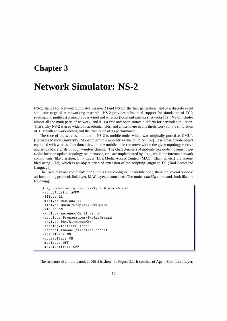
The header of COPE is defined similar to the structure the paper provides, except the first block (packetsXOR-ed together), which lists information of packets codedtogether. In COPE, asynchronous acknowl-edgment is realized with local sequence number defined and exchanged between neighboring nodes.However, it is not described clearly how the local packet sequence number is sent to the neighboringnode. Thus, in our implementation, we assign each native packet a local packet sequence number at thesender (defined as LocalPKT SEQ NUM) and include it in the first block of COPE header in the packet.The structure of the packet header looks like Figure 4.1.
For each native packet in the encoded packet, the header lists its ID (PKT ID), which is a 32-bit hashof the packet’s source IP address and IP sequence number. This IP sequence number means the numberof native packets, including native packets both directly sent and the ones encoded, sent from this node.
ENCODED_NUM
PKT_ID NEXTHOPLOCAL_PKT_
SEQ_NUM
REPORT_NUM
SRC_ID LAST_PKT Bit Map
ACK_NUM
NEIGHBOR LAST_ACK Ack Map
MAC Header
COPE Header
Routing Header
(Optional; depends on protocol)
IP Header
Reception
Report
ACK
Block
Packets
XOR-ed
together
Figure 4.1: COPE Packet Header
Note that IP sequence number is totally different from the local sequence number. IP sequence num-ber is defined by the source node of a flow (the number of native packets sends from this node to onenode or several nodes), but the local sequence numberLocal PKT SEQNUM is defined by the last hoptransmitter (the number of native packets sends to one specific neighbor).
4.8 Definition of COPE
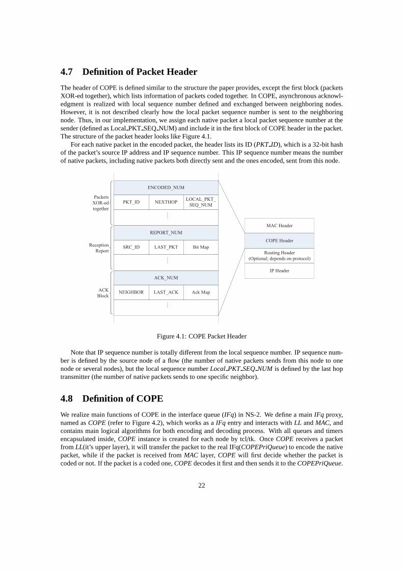
We realize main functions of COPE in the interface queue (IFq) in NS-2. We define a mainIFq proxy,named asCOPE(refer to Figure 4.2), which works as aIFq entry and interacts withLL andMAC, andcontains main logical algorithms for both encoding and decoding process. With all queues and timersencapsulated inside,COPE instance is created for each node by tcl/tk. OnceCOPE receives a packetfrom LL(it’s upper layer), it will transfer the packet to the real IFq(COPEPriQueue) to encode the nativepacket, while if the packet is received fromMAC layer, COPE will first decide whether the packet iscoded or not. If the packet is a coded one,COPEdecodes it first and then sends it to theCOPEPriQueue.
22

Otherwise, the packet is sent toCOPEPriQueuedirectly. This is because our one-queue dual-accessdesign forCOPEPriQueue, refer toCOPEPriQueuedescription in section 4.9 for detail.
Figure 4.2: COPE Structure
4.9 Definition of Queues
Each node maintains several queues, including one NonAckQueue, one AckPendQueue, one PacketPool,one PacketInfo and one ProbGuess.
4.9.1 COPEPriQueue
COPEPriQueueis the real IFq which is a multiple inheritance fromCMUPriQueueandPriQueueasshowed in the following class graph (Figure 4.3). Although NS-2 uses different IFq for different routingprotocols (e.g., AODV and DSR), here we just integrate both of them together and overwrite some of theirfunctions. In current version of COPE in NS-2, we only consider two mostly widely used routing proto-cols, AODV and DSR (due to the time reasons, only DSR is implemented), and other routing protocolscan also be included into this implementing framework easily.
As you see in Figure 4.3, both queues inherit from a common classConnectorwhich will result inan ambiguous function call, so we need to indicate a specific path while usingConnector’s members orfunctions.
Another problem is that we design the IFq much more like a BiConnector rather than just a Connector,because all packets sent up from MAC layer have to go throughCOPEprior to LL, so that the incomingpacket can be decoded byCOPEfirstly and the packet sent up to LL is native. Since the decoded nativepackets by COPE are sent up immediately without any need to store them in an “UP” queue, we simulatethe BiConnector by adding auptarget member intoCOPEto simplify this class inheritance system. Incontrast, only oneCOPEPriQueueis implemented for all “DOWN” packets, Thus theCOPEPriQueuehere is called one-queue dual-access design for IFq.
23

Figure 4.3: Class Graph for COPEPriQueue
4.9.2 NonAckQueue
In order to realize retransmission of packets sent out in a coded way, we use NonAckQueue to store allnative packets, which are sent out using network coding fromthis node, but have not been acknowledged.In other words, the uncodable packets (control packets and non-encoded packets) would not be put intoNonAckQueue.
typedef struct {
u_int16_t local_seqnum ; // local sequence number of Non -Acked pkt
u_int8_t rcounter; // counter for times of retransmission
Packet* ppkt; // pointer to packet
} non_ack_entry_t ;
typedef struct {
int nodeid; // next hop
24

list<non_ack_entry_t >* entries;
} non_ack_t;
Whenever OutputQueue sends out a native packet, which is included in an encoded packet, this nativepacket is put into the NonAckQueue. At the same time, COPE starts a timer for this native packet. Theduration of this timer slightly longer than the Round Trip Time (RTT). We call this timer NonAckTimer,which inherits from CopeTimer. If the acknowledgment of this native packet comes back before the timerexpires, the COPE stops this timer and delete this native packet from NonAckQueue. Otherwise, thisnative packet will be retransmitted, by putting it at the head of OutputQueue. And immediately, set a newtimer for this native packet and increase the retransmission counter by one. When OutputQueue sends itout, it checks the counter, if counter== 2 (retransmission threshold is 2 by default), then stop its timerand drop this packet.
4.9.3 AckPendQueue
Each node maintains an AckPendQueue for each neighboring node, each saves the pending ACK infor-mation related to the corresponding neighbor. AckPendQueue is implemented as a linked list, whosenode’s structure looks like this:
#define ACKMAP_TOTAL_SIZE 256
typedef struct {
int neighbor; //MAC address of the neighbor
u_int16_t lastack; // last ack sequence number
u_int16_t shifts; // number of bits shifted
bitset <ACKMAP_TOTAL_SIZE > ackmap;
} ack_pend_t;
4.9.4 PacketPool
PacketPool (Packet Pool), keeps a copy of all native packets it has received or sent out. To clear expiredpackets in the Packet Pool, garbage collection is conductedevery few seconds. The structure of the Pack-etPool consists of one hash table, one first-in-first-out (FIFO) queue (backup queue), and one receptionreport list.
• Hash Table
hash_map <int , Packet*> pkt_table_;
We use a hash table to store native data packets keyed on packet id. The buckets of the hash table isthe pointer of the packet corresponding to this packet id. It’s easy for COPE to do decoding whenreceiving an encoded packet, because COPE could quickly getthe corresponding packet throughits id.
• Backup QueueTo store packet pointers with FIFO strategy using the linkedlist. The purpose ofthis backup queue is to assist the process of garbage collection.
25

typedef struct {
double time;
Packet* ppkt;
} pkt_entry_t ;
list<pkt_entry_t > backup_queue_ ;
• Reception Report ListTo record which packets have been received from which neighbor, and alsowhich packets would be expired in the coming period, and be delete from Packet Pool during thegarbage collection process. This list is also the source of periodic reception reports.
#define BITMAP_TOTAL_SIZE 256
#define BITMAP_SIZE 8
typedef struct {
nsaddr_t srcip; // source ip
u_int16_t lastpkt; // ip sequence number
u_int16_t shifts; // number of bits shifted
bitset <BITMAP_TOTAL_SIZE > bitmap; // bit -map of recently heard
packets
u_int16_t max;
} report_t;
list<report_t > report_list_ ;
In Pool
When one native packet has been received or sent out, it is putinto the PacketPool. The procedure ofdoing that looks like this:
• Firstly, check whether this packet has been in the pool or not. If it is, then the packet ignored. Inaddition, check whether this packet has been garbage collected before. If so, then ignore it too.
• Secondly, push this packet into the backup queue.
• Thirdly, add this packet’s information into the hash table.
• Finally, update the reception report list according to thispacket.
Get Reception Report
There are also two situations need to get reports, just like getting ACKs from AckPendQueue. Firstly,when the node has data packet to send out, it checks whether there is any reception report to transmit, ifso, it appends them to the COPE header. Secondly, when there is no data packet to send out, then periodicreport is broadcasted as a special control packet, which contains the reception reports.
26

Garbage Collection
Without appropriate approach to clear the out-of-date packets in the pool, the pool will soon overflow.That’s why the garbage collection is used. The garbage collection is executed by COPE every few sec-onds.
4.9.5 PacketInfo
Each node keeps a hash set,packet info, that is keyed on packet id. For each packet in the output queue,the table indicates whether each neighbor has that packet ornot.
Using thegnu hashsetas the hash set implementation, wheregnu hashset is an easy-to-use hashset, but hasn’t been included into the C++ standard library. If our implementation of COPE would becompiled on other platform, there may be some compiling problems. To fix this problems, you shouldchange the including path ofhashsetto the specific platform required.
As said before, the hash table should keyed on packet id, however, to get faster access speed and betterperformance, the structure key (info key t, as showed bellow) is used rather than the packet id.
#include <ext/hash_set >
using namespace __gnu_cxx;
typedef struct {
int nodeid;
hash_set <int> pkt_ids;
} pkt_info_t;
That’s because if the hash set is keyed on packet id, when checking whether a packet is in the set ornot, true indicates the neighbor has that packet, false means not. When the sender wants to do encodingprocess and gets one neighbor’s probability of having that packet, it has to search the whole list for eachpacket, which wastes time and resources. If the packet id is used as key, the probability of each neighborhaving that packet is one entry of the hash set. That means thesender can get each neighbor’s probabilitywith high speed, which is the main advantage of hash set over other data structures.
4.9.6 ProbGuess
• General Ideas
After searching for the packet info, if the node is still not sure whether its next hop has a specificpacket or not, a probability guessing mechanism should be utilized.
The guessed probability is only used at the the encoding-needed node(subset of intermediate nodes),as a prob demander, the node will maintain an instance ofProbGuessto update probs after packet infois updated and fetch a specific prob from. To explain how probability guessing works and what’s theimplementation idea, we can consider a simple network scenario firstly as shown in Figure 4.4:
In the above simple topology, it’s obvious that A and C are source nodes with data flow A-B-E-Fand C-B-E-F separately, both B and E probably encode a nativepacket. Assume that A has sent outpackets with sequence number 1, 2, 3 and C, E have received allthese packets and kept them in theCOPEPriQueue, then we can compute the new probability at E by this way:
E maintains a table for each source ip and the entry of each table is keyed by all its neighbor nodes,at a certain time point, E receives a reception report and update the table into the following status(seeFigure 4.5, with V:exist, X:non-exist ) according to several important rules:
27

Figure 4.4: Butterfly Topology
Figure 4.5: Neighbors’ Packet Status
1. For each source ip, only update status of the packets from the smallest sequence number to thelargest sequence number defined by packets in theCOPEPriQueue(A1 to A3, C1 to C3 in theexample).
2. For the host node, status of all packets in myCOPEPriQueueshould be ’V’, since I have themall.(A1 to A3, C1 to C3 in the example)
3. If a neighbor is the source node or previous hop, it definitely has that packet (node A and B has A1,A2, A3 for sure in the example).
4. If a neighbor has sent a valid reception report, the host node knows that whether the neighbor hasa specific packet or not, thus the corresponding status should also be updated (D’s reception reportsaid that he has A1, A3 but A2 in the example).
5. If a neighbor is the destination, it shouldn’t has this packet (F’s status for A1, A2, A3 is ’X’ in theexample).
6. Otherwise, status should be ’X’ by default.
Thus, we can easily calculate a probability pc for each source ip (pc(D,A) = 2/3, p c(F,C)= 1/3), whichmeans node D has any packet originated from source A with probability equal to 2/3. p c(F,C) can also
28

be calculated similarly. As you may note, instead of evaluating each packet’s probability, we just evaluatethe probability of a set of packets sourced by a specific node.
Until now, we skip a fact that the probability is updated continuously, to increase the accuracy ofthe guessed probability, we should consider historical records as a factor and design an algorithm tocompute probability accumulatively, so a formula(as mentioned above, in ”Implementation of COPE inNS-2/Opportunistic Coding”) based on Moving Weighted Average Method which also regards updatingtime period as a coefficient.
Let’s elaborate the network scenario described before. Assuming that at node E, node D’s last recep-tion report arrived atT0 while the current report time isT1, and node D’s last probability for source A isp l(D,A), then the guessed probability is updated as
pu[D,A] = pl [D,A] + α ×T1 − T0
T× pc[D,A] (4.2)
where T is the periodical report duration, alpha is an adjusting factor.Throughout the above description, if the calculated probability is smaller than G(0.8 here), we judge
the packet is impossible to be decoded in this neighbor.
• Implementation Details
Firstly, to record all probability information, a map is constructed with a self-defined key. An updatingoperation will result in the modification of one entry in thisprob info table and the node will get a desiredprobability from here too.
Second, since packets set inCOPEPriQueueis changeable all the time, every time a new receptionreport is received, the node should modify a consistent start and end sequence number for each sourceip, then count the total number of packets (e.g. 3 from sourceA in the scenario). At the same time, alsocount the number of packets in a certain neighbor’s reception report(e.g. 2 for node D from source A inthe scenario), thus we can derive a current probability. A new structure can be used as an assistant for thisprocess, and a list of instances of this structure are created in the runtime.
typedef struct {
nsaddr_t src_ip;
uint16_t start_seq_num ;
uint16_t end_seq_num ;
int pkt_count;
} src_info_t;
Third, to record the historical updating time for each neighbor, a simple struct is designed and simi-larly create a list of instances according to different neighbor node.
typedef struct {
int nodeid;
double last_report_time ;
} nb_info_t;
Fourth, two iterfaces are provided. one is to update probinfo table after updating packetinfo, whichmeans a reception report received. This function will execute the following works:
1. update the src list information according to the large andsmall virtual queue, since the source nodesare determined while initialization, no need to change(insert/delete) the list elements dynamically.
29

2. update nbid’s nb info t, if it exists, delet add a new nbinfo t to the list, now one little problemstill exists that nothing to do if a node is no longer its neighbor.
3. get the new pktinfo, and compute a new prob with the above strategy
4. update the new prob in probinfo table, if the updated entry exists, delete it and insert a newone
5. reset the src list to a default status
Another getprob info will simply search for the hash table according to a specific source and neigh-bor, if no entry exists, return zero as the probability.
void up_prob_info (int nb_id ,
neighbor_list_node * neighbor list,
VirQueue* virtual table ,
PacketInfo* pkt_info);
double get_prob_guess (int src ip, int neighbor id);
4.9.7 VirQueue
The virtual queue is used to store all packets’ pointer in theCOPEPriQueue, sorted by the next hop andpacket type(Large/Small) pair. So a new hash table is constructed with a specificvirtual key, each entrystores a packet queue which maintains all qualified packets.
There are three main interfaces forVirQueue, the first one is inserting a packet into the virtual tableafter inserting into the output queue, the related entry is specified by nexthop id and packet size, if noentry exist, creat it dynamically, the bool parameter is to decide enque head or push back; the second oneis getting a virtual packet matching the passed parameters;the third one will remove a packet from thevirtual table, if the packet queue becomes empty after removing, just naturally delete the whole entry.
void enque_vir_pkt (Packet * p, bool rt);
PacketQueue * get_vir_pktq (int node_id , char type);
void remove_vir_pkt (Packet * p);
4.10 Timers
Each node maintains following timers to control the packet retransmission, periodic control packets, andreception reports, etc.
4.10.1 CopeTimer
CopeTimer is the parent class of other timers in COPE, which inherits from Handler. CopeTimer providessome virtual member functions for child classes.
30

4.10.2 NonAckTimer
NonAckTimer is used to manage the retransmission of unacknowledged packets. A NonAckTimer isstarted for each native packet in the encoded packet when sending out. If the acknowledgment comesback before the timer expires, the packet in the NonAckQueueis remove, and the timer of this packetis stopped. Otherwise, the timer expires. Then the retransmission process is called, by getting out thatpacket from NonAckQueue and retransmitting it, increasingthe retransmission counter by 1, and startinga new timer for this packet.
Note that, to identify which timer, the neighbor’s ID and local sequence number in that packet havebeen recorded when starting timer for it. These two variables are used to decide which timer should bestopped when receiving ACKs.
4.10.3 CtrlPktTimer
There are some periodic control packets, reception reportsand pure ACK packets in COPE, that is thereason why this CtrlPktTimer exists. This timer is started when the OutputQueue is empty, and stoppedwhen the OutputQueue contains packets. When the timer expires, the control packets are sent out.
4.11 Opportunistic Listening
COPE exploits the shared nature of the wireless broadcast medium, which creates many opportunities fornodes to overhear packets. Each node snoops on all communications over the wireless medium and storethe overheard packets for a limited periodT (the default isT = 0.5s).
In addition, each node acknowledges which packets it has heard by piggybacking the data packets thenode transmits, which is calledreception reportin this paper. If a node has no data packets to transmit, itperiodically sends the reception reports in special control packets.
As for implementation in NS-2, inheriting fromClass Tapshould be a good choice, which minimizesthe changes of NS-2. There theClass Tapis left to tap out all data packets (both encoded and native)received at this host and promiscuously snoop them for interesting tidbits. However, the problem cannotbe solved by inheriting, because there is anotherAgent DSRAgentinherits fromClass Tap. When thesetwo subclasses use the same member element in super-class, which causes some problems. Consideringthese situations, the solution is: add one more variant ofClass Tap, which is used to handle all the COPErelated incoming packets.
4.12 Opportunistic Coding
Each node create aCOPE instance which will further create a lot of assistant queues, handlers and eventimers in its init function. All encoding algorithm is implemented in COPE as mentioned before, toelaborate how encoding process is realized, we can refer to the following sequence diagram (Figure 4.6)which simulates a packetp received at a node:
• COPE receivesp with its direction ’DOWN’(1), it will firstly set the packet id and cope se-quence number to the packet’s header(2) if this is the source node, then callCOPEPriQueue’scopeprq senddownfunction(3).
• COPEPriQueuepush backp and also enquep ’s pionter into the virtual table(4), then put thispacket intoPktPool if this is the source node(5), call COPE’s encode function(7) with a dequedpacket which is from head ofCOPEPriQueue(6).
31

Figure 4.6: Downside Packet Received
• COPEfirstly get packets from virtual packet queue of all valid neighbors, then check each of themwhetherp is encodable or not. To do this, it will ’ask’PktInfoandProbGuessin order, either ofthem ’said’ yes can directly lead this packet encodable. After this,COPEwill xor all candidatepackets and append them into the cope header’s xor field, thenreturn this encoded packetres pkt.Actually, this process is much more complicated than this, so a pseudo code in the following partmay be more understandable.(8 to 14)
32

Algorithm 4.12.1: <ENCODE>(< Packet∗ p >)
comment: Encode a native packet p
RemainedNbList← Neighbors− Nexthop(p)EncodedPktList← pif size o f p< PACKET S IZE T HRES HOLD
then tag← S mallelsetag← Large
for eachget node N in RemainedNbList
do
prob← 1.0q← head o f its tag Virtual Queuefor each packet r in EncodedPktList
do
if Nextop(q) has r in local PktIn f othen prob← prob∗ 1.0
else{
get the probability Pr f or r f rom ProbGuessprob← prob∗ Pr
if prob<= Gthen exit loop
if (prob> G)
then
p← p xor qadd q to EncodedPktListdelete N f rom RemainedNbList
tag=!tagfor eachget node N in RemainedNbList
do
prob← 1.0q← head o f its tag Virtual Queuefor each packet r in EncodedPktList
do
if Nextop(q) has r in local PktIn f othen prob← prob∗ 1.0
else{
get the probability Pr f or r f rom ProbGuessprob← prob∗ Pr
if prob<= Gthen exit loop
if (prob> G)
then
p← p xor qadd q to EncodedPktListdelete N f rom RemainedNbList
assemble p′s xored header with in f omation f rom EncodedPktListreturn (p)
• COPEPriQueuecall COPE’s function to append the pend acks and reception reports into res pkt’scope header, no matterres pkt is a native packet or encoded one.(15, 18)
• COPE get the pend acks fromPendAckQueue(16, 17) and get the reception reports fromPack-etPool, the process of generating pend acks and reception reports will be seperately described inimplementation ofPendAckQueueandPktPool(19, 20).
Until now, we have completely implemented an encoding algorithm, through which any packet senddown from upper(LL) layer must go. However, many other features like setting timers for packet retrans-
33

mission and periodical control packet etc. are not reflectedin the above diagram.Note that we are only considering a sub-optimal solution, which iterates all valid neighbors in{Neighbors}-
{NextHops} with a random order , we keep the optimal solution as an open function and may extend it inour future works. For an optimal solution, we can design a setof packets as a best encoded choice priorto others.
4.13 Decoding
In the same way, we can describe the decoding process by simulating a packetp received at a node and asequence diagram (Figure 4.7) is added to help us understandthe whole process clearly:
Figure 4.7: Upside Packet Received
• COPE calls its receivable(2) member function which will further call extractstatereport(3) toupdate local packetInfo(4) and probGuess(5), then extractacks(6) to merely delete ack item withneighbor== mynodeid in non ack queue(7). Receivable function will return false(non-decodableor overheard packet) or true(native or decodable).
• COPE then calls its decode function(8) to iterate each item but in xored header field, the passedpackets also include a copy of the original target packet, this is because if the packet is non-decodable, we can recover it back for some further operations. To execute decoding process,COPEwill check its local packetPool9 confirming whether a xored packet exist or not(10). If the targetpacket is native or overheard, just return this function, otherwise, continue with other items in thexored header. In the end,COPEclears all the xored header(11) if it is decodable.
• No matter it is receivable or not, just put the result packet into PacketPool(12). We keep all non-decodable packets for a further decoding possibility, which is regarded as an extention for latterworks.
34

• Append an ack of the result packet into pendAcks if the received packet is decodable(13)
• If the packet is receivable(native or decodable packet), update packetInfo for the native or decodedpacket(14), since it is obvious that the previous hop definitely has this packet.
Note that the whole decoding process has no relation withCOPEPriQueueandVirQueue, becauseonce receiving a new packet with ’UP’,COPEjust deal with it directly rather than enqueue that packet.
4.14 Reception Report
The node knows what packets its neighbors have through reception report. Each node announces to itsneighbors the packets it stores in the Packet Pool. When a node has data packet to be sent out, it canappend the reception report got from Packet Pool if it is available. If there is no data packets to send, thenode sends the reception report periodically.
4.15 Asynchronous ACKs
In COPE, encoded packets require all nexthops to acknowledge the receipt of the associated native pack-ets. Since the synchronous approach to coded packets one by one is highly inefficient, encoded packetsare acknowledged asynchronously and cumulatively in COPE.
Neighbors’ pending ACKs are stored in the AckPendQueue. When sending out a packet, the nodetries to get pending ACKs in the AckPendQueue and append themto the COPE header. If the node hasno data packets to transmit, it sends the ACKs in periodic control packets, just like the reception report.
4.16 Control Packet
1. Allocate the COPE control packet in the cope layer, with a type tag COPECTRL/COPEDATA as theidentifier.(for cope, all other packets are regarded as normal data packet).
2. reception Report Control packet and Acks control packet are bind together, which means once oneof them is simulated to send out, the other type of field will also be assembled.
3. No need to encode the control packet, even enque it into IFq, since it is mostly probable that thereis no packet in the queue at that time.
4. Start the control packet timer when the simulator run.5. If a node receives a control packet, after updating packetinfo and ack info, this packet should be
dropped
4.17 Retransmission
There are two type of retransmission in COPE. One is retransmission of data packets, another is retrans-mission of asynchronous ACKs.
• Data Packet RetransmissionWhen the timer for the data packet in the NonAckQueue is expired,which means the nexthop has not sent back the acknowledgmentof that data packet. After theexpiration, the NonAckTimer handler will be called to process the data packet retransmission. Andthe retransmission times are limited to 2 times, after that,the node gives up and drops that packet.So the COPE does not guarantee the reliability at link layer.
35

• Asynchronous ACKs RetransmissionThis is the counterpart of data packet retransmission. Whenthe nexthop gets a duplicate data packet, which means the previous data packet lost, so the nexthopgets the pending ACKs from AckPendQueue, appends them to another data packet, and sends itout. The retransmission times for data packet are limited to2, so the retransmission times forasynchronous ACKs should be limited (2 by default), otherwise the nexthop will wait for that lostpacket forever.
4.18 Resume a packet
After completing a packet transmission, MAC will callback the passed handler’s function to resume an-other packet from IFq. Since COPE is a multiple inheritance from several queues, we define a new class,COPEHandler, as the common handler to handle the resume event. When resume is called,COPEHan-dler calls COPEPriQueue’s copeprq resume function which encapsulates both queues’ resume opera-tion.
4.19 TCP Reordering
In COPE, there is anordering agent, which ensures that TCP packets are delivered in order. The agentmaintains a packet buffer and records the last TCP sequence number passed on to up layer. If the incomingpackets that do not produce a hole in the TCP sequence stream are immediately dispatched to the transportlayer, and update the state of sequence number inordering agent. Otherwise, they are withheld in thebuffer till the gap in the sequence stream is fulled, or until a timer expires. In NS-2, thisordering agentisimplemented ascopeTcpSink, which is a subclass ofTcpSinkclass.
36

Chapter 5
Simulation and Performance
In this chapter, we evaluate the performance of TCP with COPEin different topologies using differentTCP protocols: TCP-Newreno, TCP-FeW and TCP-AP. We compareit to TCP over the baseline schemes(without COPE, no network coding).
5.1 Simulation Setup
We used NS-2 simulator (version 2.34), which is well suited for studying and research of wireless net-work, as the platform of evaluation. We considered various topologies: the most simple chain topology,shown in Figure 5.1; the classic X topology (we call it X-I topology, Figure 5.3) and X-II topology (Fig-ure 5.5) which is the extended and enhanced version of X-I topology. All of these topologies are easyto analyze and clearly show the interactions between network coding and TCP. In the MAC layer, wesimulated IEEE 802.11 with RTS/CTS (Request to Send/Clear to Send) enabled. For TCP traffic, FTP(File Transfer Protocol, is a standard network protocol used to copy a file from one host to another over aTCP-base network) traffic has been used on top of the wireless network. In all the topologies, TCP flowsstart randomly between first 2secand 3secuntil the end of the simulation.
5.2 Performance Metrics
Our evaluation uses the following metrics.
• Network Throughput:the measured total end-to-end throughput. The average throughput of allflows in the network is computed as:
throughput=receivedpacketssize× 8
simulationtime(kbps) (5.1)
• Throughput Gain: the ratio of the measured network throughputs with and without COPE[13].Throughput gain is defined as:
throughputgain=throughputCOPE
throughputNoCOPE(5.2)
wherethroughputCOPE andthroughputNoCOPE are average TCP throughput when network codingis turned on and off respectively.
37

5.3 Simulation Results
5.3.1 Chain Topology
1 2 3 mm-1
200m
…
Figure 5.1: Chain Topology
The chain topology used in this thesis as shown in Figure5.1.In the chain topology, the distance of thecontiguous nodes is 200 meters, while the transmission range of each node is 250 meters, so each node(except the first one and the last one) can only directly communicate with its two neighbor nodes arounditself. The first noden1 and the last nodenm send TCP data to each other, while they have to transmitdata through the nodes between them. So the intermediate nodes would have opportunities to do networkcoding. According to the formula of the network coding gain over chain topology [13]:
coding gain=2N
N + 1(5.3)
whereN is the number of hops in chain topology. When the number of hops N trends to infinity, thetheoretical gain should be 2.
We evaluated the three TCP protocols with and without COPE separately over the chain topology from4 hops to 15 hops. As shown in Figure 5.2, the network throughput of TCP with COPE is much higherthan the one without COPE, which proves the benefits of network coding. However, there isn’t any TCPprotocol that is absolutely the best one in all cases. We can see from Figure 5.2 that TCP-NewReno is theworst choice for network coding. While TCP-AP with COPE is much better than TCP-FeW with COPEwhen the number of hops is less than 11, after that, TCP-FeW with COPE achieves higher throughput.And regardless of which TCP protocol is used, the throughputgain of this topology is less than thetheoretical coding gain 2 as shown in formula 5.3.
5.3.2 X-I Topology
The chain topology has shown that two flows traversing the reverse path of each other, the intermediatenodes have opportunities to do network coding, and the evaluation result shows that COPE brings greatincrease to network throughput. However, in the real wireless network, there might be only a smallnumber of this kind of topology, but one would expect many flows to intersect at a relay, and thus can becoded together using opportunistic listening and guessingprobability. To achieve this goal, we use X-Itopology (Figure 5.3) as the scenario to evaluate the overhearing function of COPE.
There isn’t any gain without COPE on this topology, with 4 transmissions. But with opportunisticlistening and guessing, the middle node can code packets together and transmit the coded packet, withonly 3 transmissions. So the coding gain is 4/3 = 1.33.
Figure 5.4 shows the simulation results over X-I topology. We can see from Figure 5.4 that bothTCP-NewReno and TCP-FeW with COPE have got a little improvement of TCP performance 3% and8%, even though the coding gain is only 1.03 and 1.08 respectively, which is not as high as the theo-retical value 1.33. But they are still better than TCP-AP with COPE, which has no contribution to theTCP performance. The reasons why TCP-AP with COPE has no throughput improvement might be the
38

4 5 6 7 8 9 10 11 12 13 14 1550
100
150
200
250
300
Number of Hops
Goo
dput
(K
bit/s
)
TCP−NewRenoTCP−NewReno with COPETCP−FeWTCP−FeW with COPETCP−APTCP−AP with COPE
Figure 5.2: Throughput in Chain Topology
following two ones. One reason is TCP-AP is based on the estimation of the current 4-hop propagationdelay and coefficient of variation of recently measured RTTs. However, thistopology only has 2 hops,which might restricts the performance of TCP-AP. The other is the rate control mechanism of TCP-APcauses the output queue in COPE states hungry most of the time. That means TCP-AP is too proactive forcongestion control, so that there is only a few of packets in the output queue can be used to do networkcoding.
5.3.3 X-II Topology
To evaluate the performance of COPE and find out the reason leads to no gain when using TCP-AP, weextended the X-I topology to X-II topology (shown in Figure 5.5). It is similar to X-I topology except ithas four more nodes, so each TCP flow has 4 hops now, which satisfies the prerequisite of TCP-AP.
Without COPE, 16 transmissions are needed for all the flows tosend one packet to the destinationnode. However, if opportunistic listening and coding are permitted, the intermediate nodes have a lot ofchances to do coding process. So only 11 transmissions are necessary, the coding gain is 16/11= 1.45.
As shown in Figure 5.6, both TCP-NewReno and TCP-FeW with COPE get worse results comparedto TCP-NewReno and TCP-FeW without COPE. That’s because TCP-NewReno’s bursty behavior and tothe fact that TCP is agnostic to the underlying network coding. While TCP-FeW alleviates this burstysituation, but still not so suitable for network coding. Thesame as in X-I topology, TCP-AP with COPEstill has no contribution to the TCP Performance. So we believe that this is caused by the rate controlmechanism of TCP-AP.
39

0
2
1
4
3
150m
200m
Figure 5.3: X-I Topology
TCP−Newreno TCP−FeW TCP−AP0
100
200
300
400
500
600
700
800
Goo
dput
(Kbi
t/s)
Without COPEWith COPE
Figure 5.4: Throughput in X-I Topology
40

1
3
2
7
6
4
5
8
0
150m
200m
Figure 5.5: X-II Topology
TCP−Newreno TCP−FeW TCP−AP0
50
100
150
200
250
300
Goo
dput
(Kbi
t/s)
Without COPEWith COPE
Figure 5.6: Throughput in X-II Topology
41

Chapter 6
Proposal and Evaluation
As you may note that COPE can bring some improvement to wireless networks, but not X-II topology.And we believe that there are a lot of topologies that not suitable for network coding in the real wirelessnetworks, because they may be more complicated and unpredictable. However, we can firstly choosesome simple topologies, as the ones used in this thesis, to dosome research.
According to the results of the simulation, we find that COPE improves the network throughput, aswell as increases the packet delay at the same time over some topologies. There would be some trade-offto balance these two factors to achieve the best result. We proposed the following solutions to improvethe performance of COPE from the following two aspects: the mechanism of COPE and TCP protocols.
6.1 Encode Once
The main principle of coding is the receivers can decode the packet they want successfully. But there isno guarantee that the receivers can decode successfully every encoded packet. Consequently, they willnotify sender to retransmit the decode-error packet. The sender might encode that packet again and sendit out.
During the simulation, we find that if the receiver cannot decode one packet at the first time, and thenmost of the time it cannot decode it any more in spite of how many times that packet is retransmitted.For example, in the X-I topology, if noden1 generates an encoded packetp1
⊕
p2 which involves nativepacketp1 and p2, then broadcasts it. Noden0 andn3 receive this packet respectively, noden0 decodesit and getp1. Unfortunately, noden3 cannot decode it to get packetp2. By appending reception report,noden3 notifies noden1 that it has not got packetp2. Noden1 starts retransmission process, and encodesnative packetp2 with p3 to get another encoded packetp2
⊕
p3 and broadcasts it too. Then noden3
receives this encoded packet, but most of the time noden3 cannot decode this encoded packet involvesnative packetp2, which is the retransmission packet of COPE layer.
To overcome this problem, we modify the retransmission scheme of COPE based on the idea eachpacket could only be encoded at most one time, we call it Encode Once. Specifically, COPE directlysends out the retransmission packet as a native packet instead of encoding it again.
Figure 6.1 shows the throughput improvement of COPE with Encode Once scheme over X-I topology.We can see from Figure 6.1 that COPE with Encode Once increases the network throughput by 5%, 4%and 2% respectively compared to TCP-NewReno with COPE, TCP-FeW with COPE and TCP-AP withCOPE.
42

TCP−Newreno TCP−FeW TCP−AP0
100
200
300
400
500
600
700
800
900
Goo
dput
(Kbi
t/s)
Without COPEWith COPEWith COPE & Encode Once
Figure 6.1: Throughput of X-I topology with Encode Once
6.2 Network Coding Aware TCP
From the study of X-I and X-II topologies, we found that when the traffic load of the network linkincreases, the throughput gain of TCP-NewReno and TCP-FeW with COPE decreases, even worse thanTCP-NewReno and TCP-FeW without COPE respectively. However, TCP-AP performs stably, but stillno increase.
As we discussed in Section 2.2, TCP-AP controls the sending rate of TCP through the 4-hop propaga-tion delay and coefficient of variation of recently measured RTTs. While TCP-FeWis based on one-hoppropagation delay, so its growth of congestion window mightnot so smooth as TCP-AP’s, especiallywhen the network link suffers highly congested traffic. The core idea of TCP-FeW and TCP-AP is to re-duce the busty behavior of TCP-NewReno, so they both decrease the sending rate according to the RTTsto eliminate the probability of congestion.
On the other side, COPE carries out network coding based on the packets within the output queue.That means there should be some packets within the output queue for COPE to do network coding;however, if the output queue is always empty or holds only onepacket, there is no chance to do networkcoding, consequently no improvement, like TCP-AP with COPEover X-I topology. If there are toomany packets in the output queue which might cause severe congestion, which might lead to even worsethroughput, like TCP-NewReno and TCP-FeW with COPE over X-II topology.
To solve this problem, we take TCP-AP as the baseline to make some modifications. The generalprinciple is adapting TCP rate based on the status of the output queue to increase the opportunity ofnetwork coding, and then to maximize the throughput. Apparently, in X-I topology, the output queue doesnot contain enough packets for encoding when using TCP-AP with COPE. To increase the number of thepackets within the output queue, we reduce the rate interval, which is the duration between successivepacket, to generate appropriate number of packets. Where the appropriate number of packets means thenumber of packets is enough to let COPE do network coding on one hand, and to protect the output queuefrom overflowing on other hand.
We introduced a factorλ for the rate interval of TCP-AP, the new rate interval is calculated as the
43

following equation.
rnew= λrold (6.1)
Whererold is the original rate interval of TCP-AP andrnew is the new rate interval used in our im-provement of TCP-AP. Through various simulations and analysis, we got the experimental value ofλ,whenλ = 0.2, TCP-AP achieves the highest throughput.
Without COPE COPE Encode Once Network Coding Aware0
100
200
300
400
500
600
700
Goo
dput
(Kbi
t/s)
Figure 6.2: Throughput of X-I topology with Network Coding Aware Using TCP-AP
The Figure 6.2 shows the improvement of throughput providedby network coding aware TCP-APwith COPE. This new TCP-AP scheme brings about 12% increase of network throughput, which greatlyimproves the performance of TCP-AP in COPE.
Note that, due to the time reasons of this thesis, we didn’t test this new TCP-AP protocol over othertopologies. But we think that there should be a appropriateλ, which is suitable for TCP-AP to do networkcoding in that topology.
44

Chapter 7
Conclusions and Future Work
The purpose of this chapter is to summarize the outcome of this thesis. The planned tasks have been doneand the evaluation results have been obtained using proposed scheme. After that, the problems requiringfurther studies are discussed.
7.1 Conclusions
The key issue of this master thesis project, to evaluate and enhance the TCP performance over wirelessmultihop networks, has been finished. We implemented COPE, which is the first practical solution forwireless network coding, on NS-2 and evaluated it with threedifferent TCP protocols adapted for mobilead hoc networks, TCP-NewReno, TCP-FeW and TCP-AP, with and without COPE respectively. Weperformed several simulations over chain topology, classic X-I topology and X-II topology. The simulateresults show that both TCP-FeW and TCP-AP over chain topology could greatly improve the performanceof legacy TCP. The similar results got from the evaluation over X-I topology, except TCP-AP. Theremight be two reasons. One is TCP-AP is based on the current 4-hop propagation delay and coefficient ofvariation of recently measured RTTs. Another one is the ratecontrol of TCP-AP is over proactive, whichleads to less opportunities to perform network coding. To overcome this problem and find out the reason,I introduced X-II topology, an extended version of X-I topology, to test TCP-AP protocol. And simulationresult of X-II topology approves that the main reason is the over proactive rate control of TCP-AP.
Furthermore, to improve the current network coding gain, I proposed the following two schemesfrom the following two aspects: TCP protocols and the mechanism of COPE itself. One is Encode Oncescheme for COPE, which restricts the times of encoding for each packet to one. Both schemes bring someimprovement of throughput. Another is Network Coding AwareTCP, which is a slight modification ofcurrent TCP-AP protocol to make it less proactive and more suitable for network coding.
In the vision of wireless network coding, this thesis presents an open source solution COPE to re-searchers that allows every one to take part in and make some contributions. The extensive performanceevaluation of the system I provided, shows COPE largely increases network throughput.
Finally, it should be noticed that the real wireless networks are more complicated than the topologiesused in this thesis project. Thus the results might be very different.
7.2 Future Work
Although the evaluation of COPE shows that the COPE scheme could bring great improvement to wirelessad hoc networks, it is still far away from practical applications. Many problems need to be resolved before
45

it can be applied to the real wireless networks.
• COPE could increase the network throughput relays on schemeof network coding, which decreasesthe number of transmissions. Thus, the key problem is how to increase the probability of codingand decrease the probability of decoding error, especiallyin the complicated network scenarios, theperformance of COPE is still an open question and many related work need to be done.
• There are many factors affecting the performance of COPE in the real wireless networks, such asrouting protocol, TCP protocol, and algorithm of COPE itself, etc. More research need to be doneby considering these practical facts.
• When implementing COPE in NS-2 and evaluating it, we found that the biggest problem is not withhow to encode and decode, but with queue management. As introduced in Chapter 4, several queueshave been involved in both encoding and decoding process, especially the intermediate nodes, thisis one of the main factors affects the performance of COPE. When the network topology comesto more complicated, the performance fluctuates frequently. So this is one of the subjects for thefurther work, to propose a coding aware queue management scheme.
• We have improved the performance of COPE by using the proposed Encode Once scheme; How-ever, we believe that there should be some other parts need tobe optimized, like the strategy ofoverhearing and checking coding opportunities used in COPEright now. Memory requirementsand power consumptions are not considered in both of these strategies. The optimizations of themare conducted by our collaborate research and will be integrated into COPE in the future.
46

Bibliography
[1] R. Ahlswede, N. Cai, S.-Y. R. Li, and R. W. Yeung, “Networkinformation flow,” IEEE Trans. onInformation Theory, vol. 46, no. 4, pp. 1204–1216, Jul. 2000.
[2] Tracey Ho and Desmond S. Lun, “Network coding: an introduction,” Cambridge University Press,Cambridge, New York, 2008.
[3] S-Y. R. Li, r. W. Yeung, and N. Cai, “Linear network coding,” IEEE Trans. on Information Theory,vol. 49, no. 2, pp. 371–381, Feb. 2003.
[4] T. Ho, M. Medard, and R. Koetter, “A random linear networkcoding approach to multicast,”IEEETrans. on Information Theory, vol. 52, no. 10, Oct. 2006.
[5] S. Zhang, S.-C. Liew, and P. P. Lam, “Physical-layer network coding,” inProc. of IEEE/ACM MOBI-COM, Sep. 2006.
[6] C.-C. Wang and N. B. Shroff, “Pairwise intersession network coding on directed networks,” To appearin IEEE Tran. on Information Theory.
[7] S. Sengupta, S. Rayanchu, and S. Banerjee, “An analysis of wireless network coding for unicastsessions: The case for coding-aware routing,” inIEEE Proc. INFOCOM, May 2007.
[8] A. Khreishah, C.-C. Wang, and N. B. Shroff, “Cross-layer optimization for wireless multihop net-works with pairwise intersession network coding,”IEEE Journals on Selected Areas in Communica-tions, vol. 27, pp. 606–621, Jun. 2009.
[9] Y. Wu, P. A. Chou, and S.-Y. Kung, “Minimum-energy multicast in mobile ad hoc networks usingnetwork coding,”IEEE Trans. on Comm., vol. 53, no. 11, pp. 1906–1918, Nov. 2005.
[10] D. S. Lun, N. Ratnakar, M. Medard, R. Koetter, et al, “Minimum-cost multicast over coded packetnetworks,”IEEE Tran. on Information Theory, vol. 52, no. 6, pp. 2608–2623, 2006.
[11] T. Cui, L. Chen, and T. Ho, “Energy efficient opportunistic network coding for wireless networks,”in INFOCOM, Phoenix, AZ, USA, Apr 2008, pp. 361–365.
[12] S. Katti, S. Gollakota, and D. Katabi, “Embracing wireless interference: Analog network coding,”in Proc. of SIGCOMM, Kyoto, Japan, Aug. 2007.
[13] S. Katti, H. Rahul, W. Hu, D. Katabi, M. Medard, and J. Crowcroft, “XORs in the air: Practicalwireless network coding,” inProc. SIGCOMM, Pisa, Italy, Sep. 2006.
[14] S. Katti, H. Rahul, W. Hu, D. Katabi, M. Medard, and J. Crowcroft, “XORs in the air: Practicalwireless network coding,”IEEE/ACM Trans. on Networking, vol. 16, no. 3, pp. 497–510, Jun. 2008.
47

[15] K. Nahm, A. Helmy and C. -C. Jay Kuo, “TCP over multihop 802.11 networks: Issues and perfor-mance enhancement,” inProc. ACM MobiHoc, Urbana-Champaign, IL, USA, May 2005.
[16] G. Holland and N. Vaidya, “Analysis of tcp performance over mobile ad hoc networks,” inProc.IEEE/ACM MOBICOM, Aug 1999.
[17] K. Xu, M. Gerla, L. Qi and Y. Shu, “Enhancing TCP fairnessin ad hoc wireless networks usingneighborhood RED,” inProc. MobiCom, San Diego, California, USA, Sep 2003.
[18] Z. Fu, X. Meng and S. Lu, “How bad tcp can perform in mobilead hoc networks,” inIEEE Interna-tional Symposium on Computers and Communications (ISCC’02), Taormina, Italy, Jul 2002.
[19] K. Chandran, S. Raghunathan, S. Venkatesan and R. Prakash, “A feedback-based scheme for im-proving TCP performance in ad hoc wireless networks,”IEEE Pacific-Rim Conference on Multime-dia, vol. 8, no. 1, Feb. 2001.
[20] H. Zhai, X. Chen and Y. Fang, “Rate-based transport control for mobile ad hoc networks,” inProc.IEEE WCNC, New Orleans, LA USA, Mar 2005.
[21] L. Ding, X. Wang, Y. Xu, and W. Zhang, “Improve throughput of tcp-vegas in multihop ad hocnetworks,”Elsevier Computer Communications, vol. 31, pp. 2581–2588, 2008.
[22] L. Ding, W. Zhang, X. Wang, L. Qian, and Y. Xu, “Adaptive fractional window increment of tcp inmultihop ad hoc networks,”Journals of Zhejiang University Sience A, vol. 10, no. 6, pp. 820–827,2009.
[23] L. Scalia, F. Soldo, and M. Gerla, “Piggycode: a mac layer network coding scheme to improve tcpperformance over wireless networks,” inProc. GlobeCom, Washington, D.C., USA, Nov. 2007.
[24] P. Samuel David, and A. Kumar, “Network coding for tcp throughput enhancement over a multi-hopwireless network,” inProc. COMSWARE, Bangalore, Jan. 2008.
[25] J. Kumar Sundararajan, D. Shah, M. Medard, etc., “Network coding meets TCP,” inProc. INFO-COM, Janeiro, Brazil, Apr. 2009.
[26] L. Ding, X. Wang, Y. Xu, W. Zhang and Y. Liu, “Vegas-W: An enhanced TCP-Vegas for wirelessad hoc networks,” inProc. ICC, Beijing, China, May 2008.
[27] S. M. EIRakabawy, A. Klemm, and C. Lindemann, “TCP with adaptive pacing for multihop wirelessnetworks,” inProc. IEEE MobiHoc, Urbana-Champaign, IL, USA, May 2005.
[28] IEEE 802.11 WG, “Part 11: Wireless lan medium access control (mac) and physical layer (phy)specification,”Standard, IEEE, Aug 1999.
[29] L. S. Brakmo, S. W. O’Malley and L. L. Peterson, “TCP vegas: New techniques for congestiondetection and avoidance,” inProc. ACM SIGCOMM, Oct 1994.
[30] A. Wierman, T. Osogami and Jorgen Olsen, “A unified framework for modeling TCP-Vegas, TCP-SACK, and TCP-Reno,” inProc. MASCOTS, Orlando, FL, USA, Oct 2003.
[31] D. Traskov, N. Ratnakar, D. S. Lun, etc., “Network coding for multiple unicasts: An approach basedon linear optimization,” inProc. IEEE ISIT, Seattle, USA, Jul. 2006.
[32] T. C. Ho, Y.-H. Chan,g and K. J. Han, “On constructive network coding for multiple unicasts,” in44th Allerton Conference on Communication, Control and Computing, 2006.
48

[33] T. D. Dyer and R. V. Boppana, “A comparision of TCP performance over three routing protocols formobile ad hoc netwoks,” inProc. ACM MobiHoc, Oct 2001.
[34] S. Floyd and V. Jacobson, “Random early detection gateways for congestion avoidance,”IEEE/ACMTran. on Networking, vol. 1, no. 4, Aug 1993.
[35] H. Zhai, X. Chen and Y. Fang, “Improving transport layerperformance in multihop ad hoc networksby exploiting MAC layer information,”IEEE Transactions on Wireless Communications, vol. 6, no. 5,pp. 1692–1701, May 2007.
[36] Z. Fu, P. Zerfos, H. Luo, S. Lu, L. Zhang and M. Gerla, “Theimpact of multihop wireless channelon tcp throughput and loss,” inProc. IEEE INFOCOM, San Francisco, USA, Mar 2003.
[37] K. Chen, Y. Xue and K. Nahrstedt, “On setting TCP’s congestion window limit in mobile ad hocnetwork,” inProc. IEEE ICC, Anchorage,Alaska, May 2003.
[38] E. Kohler, robert Morris, B. Chen, J. Jannotti, and M. F.Kaashoek, “The click modular router,”ACM Trans. Computer Systems, Aug 2000.
[39] Wikipedia, “Wireless Ad Hoc Network,” http://en.wikipedia.org/wiki /Wirelessad hoc network, ac-cessed on Jan 2011.
[40] RFC 793, “TRANSMISSION CONTROL PROTOCOL,” http://www.faqs.org/rfcs/rfc793.html,Sep1981.
[41] Wikipedia, “Transmission Control Protocol,” http://en.wikipedia.org/wiki /TransmissionControlProtocol, accessed on Jan 2011.
[42] M. Allman, V. Paxson, and M. Stevens, “TCP Congestion Control,” RFC 2581, Apr 1999.
[43] A. Bakre and B. R. Badrinath, “I-TCP: indirect TCP for mobile hosts,” inProceedings 15th Inter-national Conference on Distributed Computing Systems (ICDCS), pp. 136-143, May 1995.
[44] K. Brown and S. Singh, “M-TCP: TCP for mobile cellular networks,” ACM SIGCOMM ComputerCommunication Review, vol. 27, no. 5, pp. 19-42, October 1997.
[45] J. Border, M. Kojo, J. Grinder, G. Montenegro and Z. Shelby, “Performance Enhancing Proxies,”INTERNET-DRAFT: http://tools.ietf.org/html/draft-ietf-pilc-pep-04, accessed on Jan 2011.
[46] P. Sinha, N. Venkitaraman, R. Sivakumar, and V. Bharghavan, “WTCP: A reliable transport protocolfor wireless wide-area networks,”Proceedings of ACM Mobicon’99, Seattle, WA, pp. 231-241, 1999.
[47] S. Mascolo, C. Casetti, M. Gerla, M. Sanadidi, and R. Wang, “TCP westwood: bandwidth estima-tion for enhanced transport over wireless links,”ACM SIGMOBILE, pp. 287-297, 2001.
[48] S. Floyd and T. Henderson, RFC 2582: “The NewReno Modification to TCP’s Fast Recovery Algo-rithm,” http://www.ietf.org/rfc/rfc2582.txt, April 1999.
[49] Z. Fu, P. Zerfos, H. Luo, S. Lu, L. Zhang, and M. Gerla, “The Impact of Multihop Wireless Channelon TCP Throughput and Loss,” inIEEE INFOCOM’ 03, Mar. 2003.
[50] Kitae Nahm, Ahmed Helmy, C.-C. Jay Kuo, “TCP over 802.11Multihop Networks: Issues andPerformance Enhancement,”Proc. of ACM Mobihoc 2005, May 2005.
[51] S. M. EIRakabawy, A. Klemm, and C. Lindemann, “TCP with Adaptive Pacing for Multihop Wire-less Networks,” inProceedings of ACM MOBIHOC, pp. 288-299, May 2005.
49

[52] NS-2, http://nsnam.isi.edu/nsnam/index.php/Main Page, access on Jan 2011.
[53] S. Li, R. Yeung, and N. Cai, “Linear Network Coding,” inIEEE Transactions on Information The-ory, Vol. 49, No. 2, pp. 371-381, 2003.
[54] T. Ho, R. Koetter, M. Medard, D. R. Karger and M. Effros, “The Benefits of Coding over Routingin a Randomized Setting,”International Symposium on Information Theory (ISIT), 2003.
[55] B. Ni, N. Santhapuri, Z. Zhong and S. Nelakuditi, “Routing with opportunistically coded exchangesin wireless mesh networks,” inProc. of WIMESH 06.
50