Embed Size (px)
Citation preview
18 TRANSPORTATION RESEARCH RECORD lll3
Evaluation and Management of Underground Tank Systems
DAVID H. KROON
Development of an Integrity Assurance Program for existing underground tanks Includes soil borings for detection of conhtminaiion; fieid testing to determine the eiectricai and chemical properties of the tank system and surrounding environment; computer modeling to assess the potential for corrosion and assign a Priority Index; precision tank testing, inventory analysis and repairs; and retrofitting with cathodic protection. A program is presented that provides the framework for making decisions that satisfy the requirements for safety, economics, and regulations.
The Environmental Protection Agency (EPA) estimates that approximately one-third of the non-farm, underground tanks within the United States are leaking. The average leak rate of 208 gallons per month for each tank results in an extraordinary source of contamination for our water supplies and our environment in general.
During the first year of service, by far the largest cause of leaks is mechanical failure related to poor construction practices, including improper backfilling and loose connections. The tank-related piping is particularly susceptible to failure and continues to be a major source of leakage through the life of the tank system. Clearly, however, after the first several years of service, the principal cause of underground tank leakage is corrosion.
In this general context, the corrosion of fiberglass tanks and piping must also be considered (Figure 1). The focus of this paper will, however, be on the electrochemical corrosion of steel and the establishment of integrity assurance programs for underground steel tank systems. It should be recognized that all of the following information pertains not only to steel tanks, but also to steel components (e.g., pipe, fittings) of any underground tank system. Operators of existing underground tanks are faced with the problem of how best to manage their systems. In recent years, concerns for safety, environmental protection, and public liability have risen dramatically. The EPA Interim Prohibition and pending federal regulations, plus the existing state and local requirements, have all served to bring these issues to the attention of the highest levels of management. An Integrity Assurance Program (IAP) is necessary to ensure that tank system operations are safe, comply with applicable regulations, and limit exposure to unnecessary liabilities.
Fortunately, addressing these issues can provide a real benefit for the underground tank operator. A properly planned IAP not only provides public safety and compliance with regulations, but also serves to protect the owner's capital investment,
Corrpro Companies, Inc., P.O. Box 2701, Spring, Tex. 77383.
minimize public liability, and reduce operating costs for repairs and replacement. The IAP must be well planned to ensure that the owner enjoys the full economic benefits of the program.
CORROSION OF STEEL TANKS
The forms and mechanisms by which steel corrodes underground are well established. For underground steel tanks, the rate of external corrosion, leading to the penetration of the tank ¥.'!!!!, is l!!rge!y determi.T!ed by
• Quality and longevity of dielectric coating. • Differential in oxygen concentration from top to bottom. • Homogeneity of backfill. • Ground-water composition and fluctuation. • Chemical and electrical properties of surrounding soil. • Impact of stray D.C. earth currents.
Much of our knowledge about the performance of steel underground has resulted from the study of pipelines. There are, however, two very significant differences between the corrosion of underground tanks and pipelines: (a) a tank is of much larger diameter, and (b) the operation of a tank system is far different from that of a pipeline.
In the first instance, the larger diameter inevitably increases the difference between the available oxygen at the top of the tank and that at the bottom. This, therefore, creates intense oxygen concentration corrosion cells. The large diameter also enhances accelerated rates of corrosion because of fluctuations
FIGURE 1 Fiberglass tank failure.
Kroon
in the water table, temperature variations, and non-homogeneous backfill.
The tank operation itself also contributes to the corrosion. The cyclical nature of filling and emptying causes changes in temperature, pressure, tank end deflection, and so on. Probably the most significant impact, however, is on the dielectric coating. Product spillage regularly deteriorates the coating to the extent that the top surfaces of most older petroleum product tanks coated with coal tar enamel are virtually bare (Figure 2).
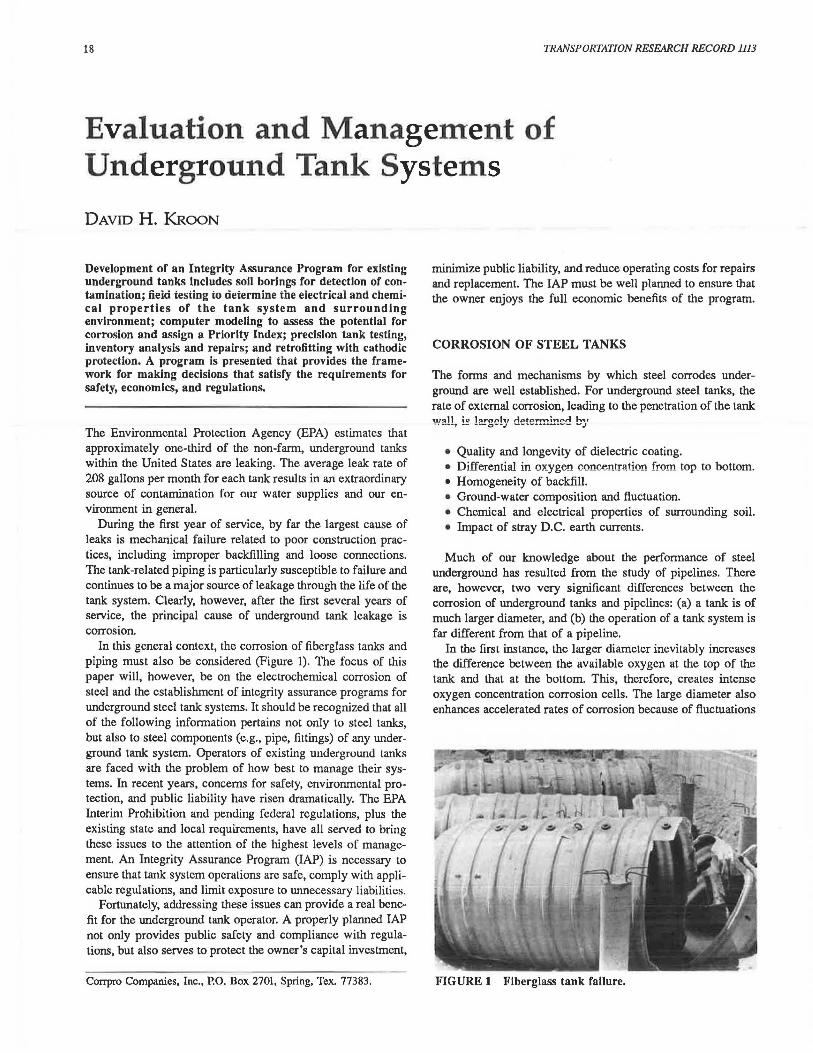
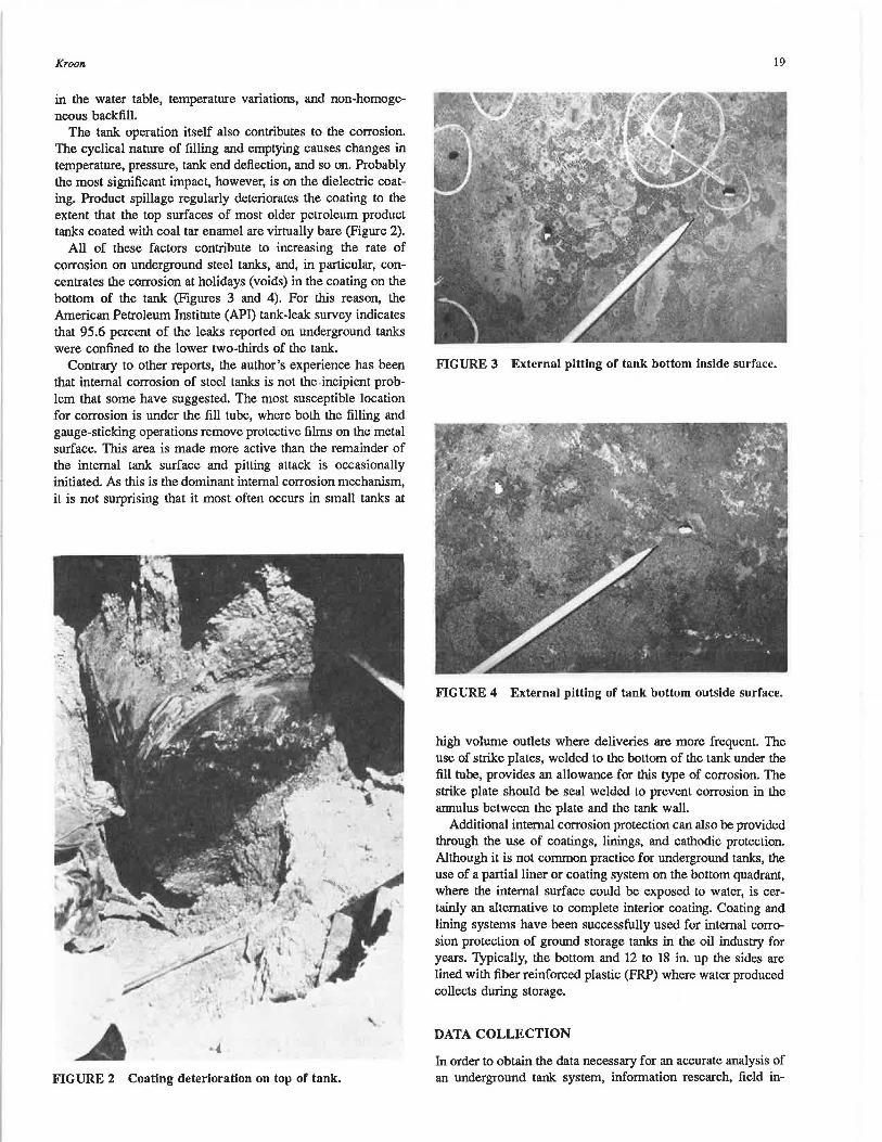
All of these factors contribute to increasing the rate of corrosion on underground steel tanks, and, in particular, concentrates the corrosion at holidays (voids) in the coating on the bottom of the tank (Figures 3 and 4). For this reason, the American Petroleum Institute (API) tank-leak survey indicates that 95.6 percent of the leaks reported on underground tanks were confined to the lower two-thirds of the tank.
Contrary to other reports, the author's experience has been that internal corrosion of steel tanks is not the -incipient problem that some have suggested. The most susceptible location for corrosion is under the fill tube, where both the filling and gauge-sticking operations remove protective films on the metal surface. This area is made more active than the remainder of the internal tank surface and pitting attack is occasionally initiated. As this is the dominant internal corrosion mechanism, it is not surprising that it most often occurs in small tanks at
FIGURE 2 Coating deterioration on top of tank.
19
FIGURE 3 External pitting of tank bottom inside surface.
FIGURE 4 External pitting of tank bottom outside surface.
high volume outlets where deliveries are more frequent. The use of strike plates, welded to the bottom of the tank under the fill tube, provides an allowance for this type of corrosion. The strike plate should be seal welded to prevent corrosion in the annulus between the plate and the tank wall.
Additional internal corrosion protection can also be provided through the use of coatings, linings, and cathodic protection. Although it is not common practice for underground tanks, the use of a partial liner or coating system on the bottom quadrant, where the internal surface could be exposed to water, is certainly an alternative to complete interior coating. Coating and lining systems have been successfully used for internal corrosion protection of ground storage tanks in the oil industry for years. Typically, the bottom and 12 to 18 in. up the sides are lined with fiber reinforced plastic (FRP) where water produced collects during storage.
DATA COLLECTION
In order to obtain the data necessary for an accurate analysis of an underground tank system, information research, field in-
20
spections, field tests, and laboratory testing should be performed. All test methods should be in accordance with standard engineering practices.
Information research is performed to include a review of site drawings, construction specifications, and operational history at each location. The following information is collected, where available, about the underground tank installations:
• Location, contents, capacity and dimensions, and fre-quency of deliveries;
• Coating and backfill material; • Age and leak history; • Piping materials and location of vent and dispensing lines;
and ~ Electrical isolation and use of insulating fittings.
A visual inspection is performed on arrival at an underground tank site, and the following observations are recorded about the area:
• Existing utilities • D.C. transit systems • Underground aquifer • Basements • Potable water supply • Navigable waterway • Public buildings
A stray DC earth current monitor is established to detect the presence, if any, of DC interference currents from foreign sources. The monitor consists of a microprocessor-controlled field data collection unit in conjunction with a reference cell placed in contact with the soil. Electrolytic (stray current) corrosion can result from the operation of DC transit systems, improper ground of DC arc welders, mining equipment, or foreign cathodic-protection systems. Electrolytic corrosion on underground tank systems can be very severe when stray currents are affecting the structures.
All tanks are located and, where possible, capacity, dimensions, and the presence of steel product and vent piping are confirmed. Using a tank gauge stick equipped with a pointed probe, the extent of internal corrosion immediately below the fill cap is recorded.
Locations for soil borings are then selected. At sites with from one to four tanks, typically two test holes should be bored. The holes are located approximately 1 ft from the tanks (within the tank backfill) and are drilled to a minimum depth of 2 ft below the deepest tank. A number of measurements are recorded in each test hole as the boring progresses such as
• Concentration of hydrocarbon vapors in the soil, • Tank-to-soil potential profile, • Soil-resistivity profile, and • Depth of water table.
Soil samples are extracted from the bore holes and placed in sealed sample jars for laboratory analysis. These are then sent to a soils laboratory where the following tests are performed:
• Conductivity •pH
TRANSPORTATION RESEARCH RECORD 1113
• Sulfide ion concentration • Chloride ion concentration • Moisture content • Type classification (aeration)
Through the use of a soil vapor hydrocarbon detector, an analysis of the presence of gasoline in the soil is performed during the boring operation. A typical approach is to test 1 ft below grade, at the middle and bottom of the boring. Where gasoline is detected in the borings, an additional 5 and 10 ft can then be drilled and tests performed. These tests indicate the concentration of gasoline in the soil vapor from 30 to 1,000 ppm. Where the detection of other hydrocarbons is necessary, specific chromatographic tubes are used for the specific vapor. If the level of recoverable comamination is desired, the soii samples can be tested for total petroleum hydrocarbons recoverable through the use of freon extraction and an infrared spectrophotometer.
DATA ANALYSIS
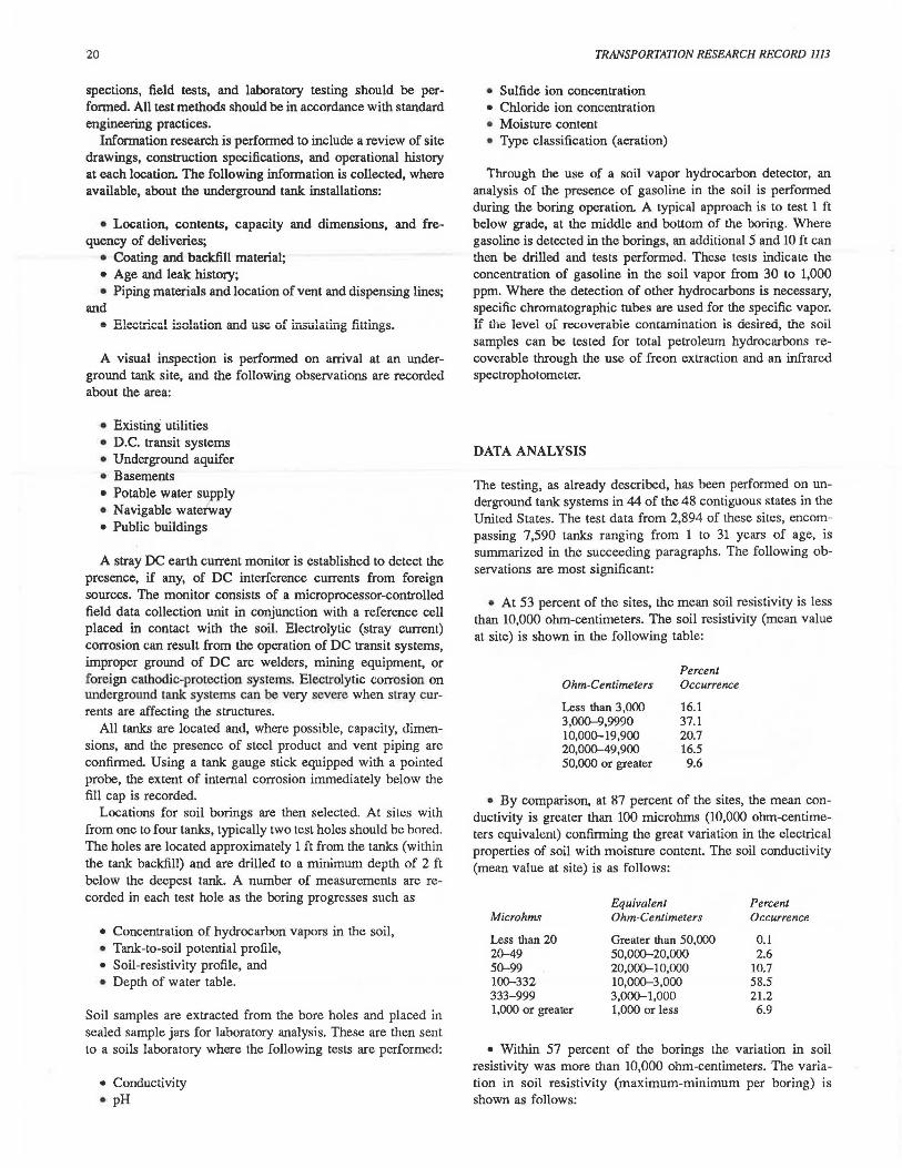
The testing, as already described, has been performed on underground tank systems in 44 of the 48 contiguous states in the United States. The test data from 2,894 of these sites, encompassing 7,590 tanks ranging from 1 to 31 years of age, is summarized in the succeeding paragraphs. The following observations are most significant:
• At 53 percent of the sites, the mean soil resistivity is less than 10,000 ohm-centimeters. The soil resistivity (mean value at site) is shown in the following table:
Ohm-Centimeters
Less than 3,000 3,000-9,9990 10,000-19,900 20,000-49,900 50,000 or greater
Percent Occurrence
16.1 37.1 20.7 16.5 9.6
• By comparison, at 87 percent of the sites, the mean conductivity is greater than 100 microhrns (10,000 ohm-centimeters equivalenl) confirming the great variation in the electrical properties of soil with moisture content. The soil conductivity (mean value at site) is as follows:
Equivalent Percent Microhms Ohm-Centimeters Occurrence
Less than 20 Greater than 50,000 0.1 20-49 50,000-20,000 2.6 50-99 20,000-10,000 10.7 100-332 10,000-3,000 58.5 333-999 3,000-1,000 21.2 1,000 or greater 1,000 or less 6.9
• Within 57 percent of the borings the variation in soil resistivity was more than 10,000 ohm-centimeters. The variation in soil resistivity (maximum-minimum per boring) is shown as follows:
KrOOll
Ohm..C•ntimelers
Less than 3,000 3,000--9,999 10,000--19,999 20,000--49,999 50,000 or greater
Percent Occurr•nce
17.4 25.3 19.4 20.2 17.7
• The tank-to-soil potential profile varied within a boring by 40 millivolts or more, in 47 percent of the cases. The variation in tank-to-soil potential (maximum-minimum per boring) is shown in the following table:
Millivolts Percenl Occurrence
Less than 20 25.3 20-39 27.8 40-59 17.7 60--79 11.2 80 or greater 18.0
• Stray currents causing fluctuations in tank-to-soil potential of 100 millivolts or greater were recorded at 2 percent at the locations.
• One penetration was detected because of internal corrosion under the fill. In 40 percent of the tanks the surface was rough, indicating some internal pitting.
• Soil vapors indicated the presence of product in 24 percent of the soil samples; however, the concentration was greater than 30 ppm in only 9 percent of the tests.
• At 55 percent of the sites, the mean value of the soil pH fell between 8 and 10. The alkaline conditions are largely due to the use of degreasers to clean the tank pad. The soil pH (mean value at site) is shown in the following table:
pH
4.0 or less 4.1-6.0 6.1-7.0 7.1-8.0 8.1-10.0 Greater than 10.0
Percent Occurrence
0.1 5
10 27 55
3
• In 64 percent of the cases, the mean soil moisture content was less than 10 percent. The soil moisture content (mean value at site) is shown as follows:
Percent Dry Weight
Less than 5.0 5.0-9.9 10.0-14.9 15.0-19.9 20.0-24.9 25 or greater
Percent Occurrence
15.2 48.3 27.0 7.6 1.2 0.7
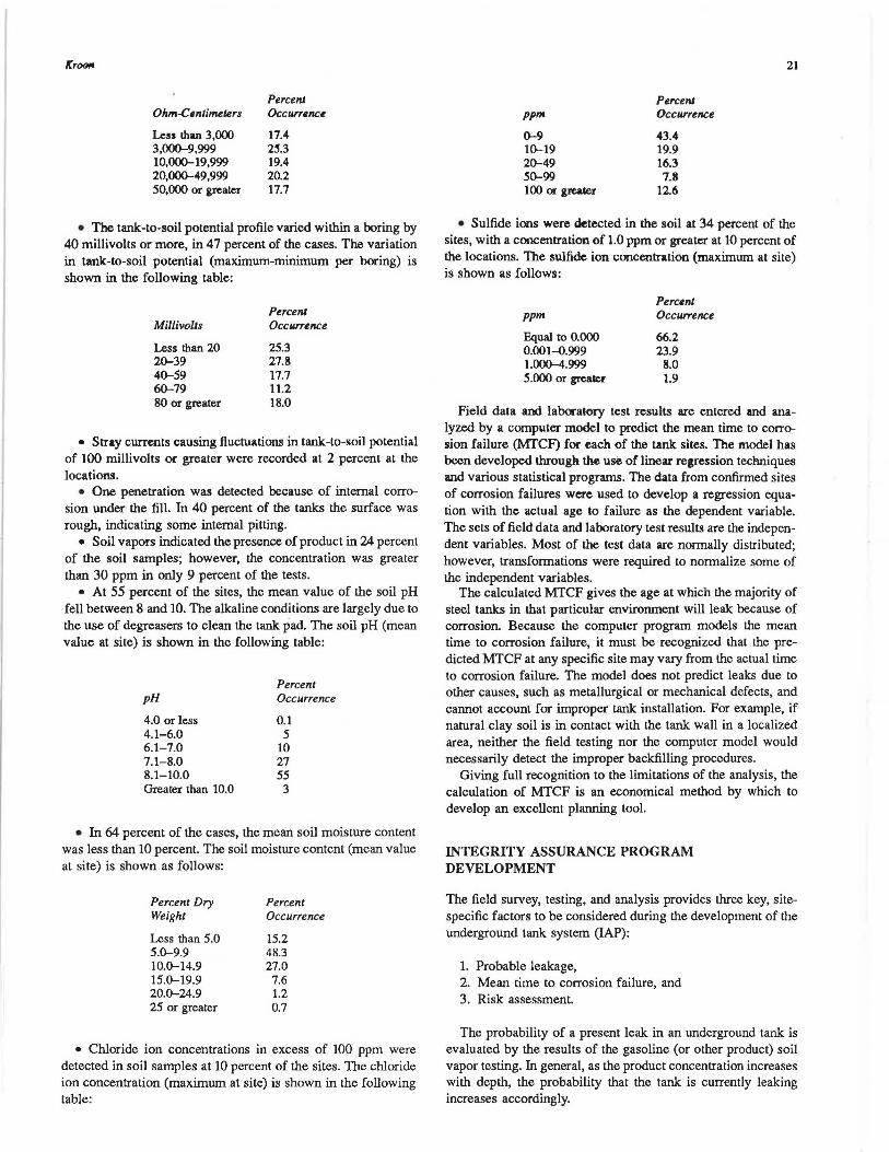
• Chloride ion concentrations in excess of 100 ppm were detected in soil samples at 10 percent of the sites. The chloride ion concentration (maximum at site) is shown in the following table:
ppm
0-9 10-19 20-49 S0-99 100 or gl'Cater
Percenl Occurrence
43.4 19.9 16.3 7.8
12.6
21
• Sulfide ions were detected in the soil at 34 percent of the sites, with a concentration of 1.0 ppm or greater at 10 percent of the locations. The sulfide ion concentration (maximum at site) is shown as follows:
ppm Percent Occurrence
Equal to 0.000 66.2 0.001-0.999 23.9 1.000-4.999 8.0 5.000 or great.er 1.9
Field data and laboratory test results are entered and analyzed by a computer model to predict the mean time to corrosion failure (MfCF) for each of the tank sites. The model has been developed through the use of linear regression techniques and various statistical programs. The data from confirmed sites of corrosion failures were used to develop a regression equation with the actual age to failure as the dependent variable. The sets of field data and laboratory test results are the independent variables. Most of the test data are normally distributed; however, transformations were required to normalize some of the independent variables.
The calculated MTCF gives the age at which the majority of steel tanks in that particular environment will leak because of corrosion. Because the computer program models the mean time to corrosion failure, it must be recognized that the predicted MTCF at any specific site may vary from the actual time to corrosion failure. The model does not predict leaks due to other causes, such as metallurgical or mechanical defects, and cannot account for improper tank installation. For example, if natural clay soil is in contact with the tank wall in a localized area, neither the field testing nor the computer model would necessarily detect the improper backfilling procedures.
Giving full recognition to the limitations of the analysis, the calculation of MTCF is an economical method by which to develop an excellent planning tool.
INTEGRITY ASSURANCE PROGRAM DEVELOPMENT
The field survey, testing, and analysis provides three key, sitespecific factors to be considered during the development of the underground tank system (IAP):
1. Probable leakage, 2. Mean time to corrosion failure, and 3. Risk assessment.
The probability of a present leak in an underground tank is evaluated by the results of the gasoline (or other product) soil vapor testing. In general, as the product concentration increases with depth, the probability that the tank is currently leaking increases accordingly.
COAR PRO TANK
6YSTDI EllolLUATION
LOW l'RIORITY
INDEX(PJI
LEAKAGE DETECTED
.. GH
PRIORITY
INDEX IPll
PRIORITIZE
CLEAN UP
EVALUATION
PRECISION TllNK
TESTING
INVENTORY llllALYSIS
l'l.AMIJING ld>4IETING
LEAK LOCJITED
LEAICAGE DETECTED
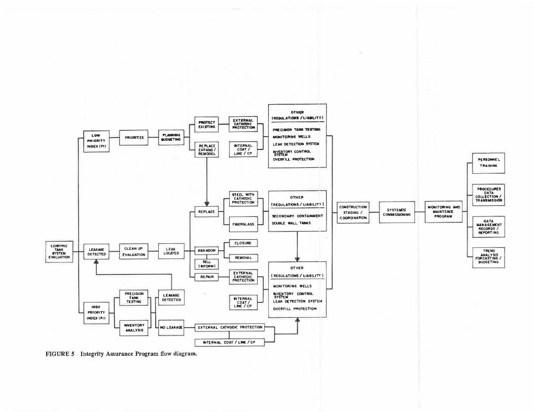
FIGURE 5 Integrity Assurance Program flow diagram.
~CT VUSTlllG
REP\.ACE EXPAllO I REMODEL
EXTEllllAL CATMODIC
PROT[CTlON
INTEllNAL COAT I
LINE I CP
STEEL WITH CATHODIC
PROTECTION
FIBERGLASS
CLOSURE
REMOVAL
EXTEllNAL CATHODIC
PROTECTION
INTERNAL COAT I
LINE I CP
EXTERNAL CATHODIC PROTECTION
INTEllNAL COAT I LINE I CP
OTHlll
(RDIULATI°"' /LJAllLJTY I
PRECI- TANK T[ITlll8
-IT01111141 WELLS
LEAK DETECTIC* 5YST£111
~rcoNTllOl.
OVERFILL PROTECTION
OTHER
( REGULA.TIONS I LIABILITY I
SECONDARY CDllTAINllDtT
DOU8L£ WALL TANKS
OTHER
(REGULATIONS/ LIABILJTV)
MONITORING WELLS
.. VENTDRY CONTROL SYSTEM
LEAK DETECTION SYSTEhl
OVER Fl LL PROTECTION
CONSTRUCTION
STAGING I COORDINATION
SYSTEllJIS) CC)M .. SSJONING
lllONITOlllNG ANO lllAINTENCE PRO GR A Ill
PERSONNEL
TllAINING
PllOCEDUll£S DATA
COLLECTION I TRANS .. SSIOll
DATA MANAGEMENT
RECORDS I REPORTING
TR ENO ANALYSIS
FORCASTING I BUDGETING
Kroon
The MTCF is used to calculate a PI by subtracting the MTCF from the actual age of the tank. This PI is then used to assign priorities to each of the tank sites. The site information regarding the location at public buildings, water supplies, and so on, is used to assess the exposure and risks related to a tank failure, should leakage occur.
The results for each underground tank system are placed in three general categories:
1. Probable leakage, 2. High PI, and 3. Low Pl.
Within each category, locations are prioritized in order of importance. The IAP includes a number of recommended actions for each category of tank. These may include
• Inventory analysis; • Precision tank testing; • Repairs or Replacement; • External and Internal corrosion protection, or both; and • Overfill protection
For reasons of reduced liability by improved leak detection techniques, and regulatory requirements, other elements of the program may include
• Leak detection systems, • Inventory control systems, and • Monitoring wells
Where leakage is probable, the presence of an existing leak should be confirmed, and appropriate steps taken to evaluate the degree of contamination and cleanup requirements. A business decision must then be made as to whether to repair, replace, or abandon the tank. If repairs are made, the tank should be retrofitted with external cathodic protection. Internal corrosion protection can also be considered at that time. If the tanks are to be abandoned, proper closure or removal procedures must be followed. If the tanks are to be replaced, then either fiberglass or steel with cathodic protection should be chosen. In both cases, corrosion protection is recommended for steel piping incorporated in the underground tank systems. The need for monitoring wells, inventory control systems, leak detection systems, and overfill protection should also be evaluated in order to coordinate all construction activities at the site.
At sites with a relatively high PI, a detailed inventory analysis or precision tank testing should be performed to determine whether the system is presently tight. If a leak is detected, the procedures outlined previously should be followed. If there is no leakage, retrofitting with external cathodic protection is recommended. Consideration should also be given to internal corrosion protect~on, monitoring wells, inventory control sys-
23
terns, and overfill protection. The decision on whether these additional elements should be included in the IAP are largely based upon considerations for reducing exposure to public liability, and possible regulatory requirements.
In the low PI category, the indices present the order of importance for addressing the sites. If a decision is made to maintain the existing underground tank systems, then retrofitting with external cathodic protection for the tank and piping should be considered in addition to order elements of the IAP.
All decisions must be reached after due consideration for safety, economics, and regulations. The IAP is summarized on the decision flow diagram (Figure 5).
ECONOMIC BENEFITS
Some of the greatest direct economic benefits to the tank system owner-operator accrue during the construction staging and coordination, and monitoring and maintenance phases of the IAP. By properly planning the cons\ruction of all elements of the program, considerable savings in site Work (e.g., excavations, concrete) can be realized. Following installation and commissioning of the systems, a most important element of the overall IAP remains to be addressed. Data collection, transmission, and management systems are essential for maximizing the economic benefits of the program that result from improved trend analysis, forecasting, and budgeting.
The decisions on which elements to incorporate in an IAP should give top priority to leak prevention. Leak detection is a secondary, after the fact, concern.
Past experience with operators of underground tanks indicates that a comprehensive approach to the problem of controlling corrosion and reducing exposure to public liability usually costs less than 25 percent of overall tank system replacement. Tank replacement also has the disadvantage of exposing the operator to the first year of system installation, when the majority of leaks occur.
The testing and evaluation procedures presented offer an economical method by which a great deal of information can be collected for good planning and budgeting. When the appropriate business factors are combined with the results of the indexing, decisions can be made concerning such related factors as expansion. remodeling, and abandonment.
The test program not only evaluates the potential for corrosion and defines a priority index for each site, it also alerts the operator to concerns for existing spillage and probable tank leakage. Immediate steps can then be taken to protect the environment and the company.
Publication of this paper sponsored by Committee on Corrosion .