Embed Size (px)
Citation preview
Journal of Stress Analysis
Vol. 1, No. 2, Autumn − Winter 2016-17
Evaluation Effects of Modeling Parameters on the Tem-
perature Fields and Residual Stresses of Butt-Welded Stain-
less Steel Pipes
S. Feli∗, M.E. Aalami Aaleagha, M.R. JahanbanMechanical Engineering Department, Razi University, Kermanshah, Iran.
Article info
Article history:Received 2016.07.22Received in revised form2016.10.31Accepted 2017.02.13
Keywords:Residual stressButt-weldedStainless steel pipeTemperature field
Abstract
In this paper, the effects of modeling parameters on the temperature fieldand residual stresses of butt-welded stainless steel pipes were investigated byusing finite element modeling in ABAQUS code. The investigated parametersincluded, heat flux distribution, latent heat, and heat flux type. The birth anddeath techniques were utilized to consider mass addition from Y308L fillermetal into the weld pool. The moving heat source and convection heat transferwere also modeled by a user subroutine DFLUX and FILM in ABAQUS code.In this work, for verification of FE modeling the temperature fields and residualstresses were compared with available experimental results. The simulationresults showed that heat flux with a double ellipsoidal distribution proposedby Goldak associated with latent heat parameter and employed a fully volu-metric arc heat input, representing the best match with the experimental data.
1. Introduction
Fusion welding is a joining process in which the coalescence of metals is achieved by fusion. This form ofwelding is widely employed in fabricating structuressuch as ships, offshore structures, steel bridges, andpressure vessels. Owing to localized heating by thewelding process and subsequent rapid cooling, resid-ual stresses can arise in the weld itself and in the basemetal. Residual stresses attributed to welding pose sig-nificant problems in the accurate fabrication of struc-tures because those stresses heavily induce brittle frac-turing and degrade the buckling strength of weldedstructures. Residual stresses during welding are un-avoidable and their effects on welded structures can-not be disregarded. Design and fabrication conditions,such as the structure thickness, joint design, weldingconditions and welding sequence, must be altered sothat the adverse effects of residual stresses can be re-duced to acceptable levels. Therefore, estimating themagnitude and distribution of welding residual stresses
and characterizing the effects of certain welding condi-tions on the residual stresses are particularly impor-tant.
In the last decade several FE models have beenproposed to predict temperature fields and residualstresses in multi-pass butt-welded steel pipes.
Deng and Murakawa [1] compared the numericalsimulated results of both the temperature field and thewelding residual stress field with experimental mea-surements for stainless steel pipes. The 2D axisym-metricand 3D models were also developed. The resultsshowed that a 2D axisymmetric model can also givea reasonable prediction for both the temperature fieldand the residual stress field in stainless steel pipe ex-cept for the welding start-finish location.
Brickstad and Josefson [2] employed a 2D axisym-metricmodel to numerically simulate a series of multi-pass circumferential butt-weldingof stainless steel pipein a non-linear thermo mechanical FE analysis. Tso-Liang et al. [3] evaluated the residual stresses with var-ious types of welding sequence in single pass, multi pass
∗Corresponding author: S. Feli (Associate Professor)E-mail address: [email protected]
25

butt-welded plates and circular patch welds. This in-vestigation has provided an available welding sequenceto enhance the fabrication process of welded structures.
Lee and Chang [4] presented parametric studieswith inside radius to wall thickness ratio ranging from10 to 100 to investigate the effects of pipe diameteron residual stresses. Sattari-far and Farahani [5] inves-tigated the effects of the weld groove shape and passnumber on residual stresses in butt-welded pipes. Itwas shown that these two parameters may have signif-icant effects on magnitude and distribution of residualstresses in welded pipes.
Feli et al. [6] used the 3D and 2D axisymmetric FEmodel to investigate the welding temperature field andthe residual stress distribution for thin-walled pipes.Also the effects of welding sequences on the thermaland structural analysis were investigated. Four typesof welding sequences for circular welds of pipe wereused and concluded that except the starting point ofwelding, there are no important differences of axial andhoop residual stresses for welding sequences.
Foroutan et al. [7], investigated the effect of hydro-static testing internal pressure on the residual stressesof circumferentially butt-welded steel pipes by a three-dimensional finite element simulation. The results ob-tained from this study showed that the hydrostatictesting pressure has a significant effect on residualstresses.
In this study, a 3D finite element simulation was de-veloped to investigate the distribution of temperaturefields and residual stresses during two-pass tungsten in-ert gas arc welding in a stainless steel pipe. In this nu-merical simulation, the uncoupled thermal-mechanicalmodel, the temperature dependent thermal-physicalproperties and the add and remove elements in thethermal and structural analysis, were utilized. The ef-fects of heat flux distribution, latent heat, and heat flux
type on temperature fields and residual stresses werealso investigated and temperature fields axial and hoopresidual stresses were compared.
2. FE Simulation of the Welding Process
In this section by using ABAQUS 6.8-1 software, a3D thermal elastic-plastic FE computational proce-dure was employed to simulate the welding temper-ature fields and residual stresses in stainless steel pipe.The analysis included two steps. The first step wasthat the heat conduction problem which was solvedindependently from the thermal analysis to obtainthe temperature distribution with time and space andin the second step the temperature history in eachnode was employed as the thermal load in the subse-quent mechanical analysis and distribution of stressesin pipe was determined. The temperature-dependentthermal-physical properties of SUS304 stainless steelpipe such as specific heat, conductivity, density, andtemperature-dependent thermal-mechanical propertiesincluding young’s modulus, Poisson’s ratio, thermal ex-pansion coefficient, and yield strength were used forthermal analysis and mechanical analysis respectively.The thermal and mechanical properties of SUS304areshown in Table 1. In this paper based on the refer-ence [8], the mechanical properties of weld metal wereassumed to be the same as base metal.
The 3D finite element model of pipe with 22000brick elements is shown in Fig. 1. Also the weld-ing arc travel direction and welding start/stop position(θ = 0◦) is shown in the Fig. 1. Because of the symme-try, one half of the model was selected as the analysismodel, which had a fine grid in the welding zone. Thesmallest element was 3.5 × 1.5 × 0.8mm. The length,the outer diameter and the thickness of the pipe were400mm, 114.3mm and 6mm, respectively.
Table 1Thermal physical properties and mechanical properties of SUS304 [1].
Temperature◦C
Specific heatJ/g◦C
Conductivityj/mm◦Cs
Densitygr/mm3
Yield stressMPa
Thermalexpansion
◦C−1
Young’smodulusGPa
Poisson’sratio
0 0.462 0.0146 0.79 265 1.7e-5 198 0.294100 0.496 0.151 0.788 218 1.74e-5 193 0.295200 0.512 0.0161 0.783 186 1.8e-5 185 0.301300 0.525 0.0179 0.779 170 1.86e-5 176 0.310400 0.540 0.0180 0.775 155 1.91e-5 167 0.318600 0.577 0.0208 0.766 149 1.96e-5 159 0.326800 0.604 0.0239 0.756 91 2.02e-5 151 0.3331200 0.676 0.0322 0.737 25 2.07e-5 60 0.3391300 0.692 0.0337 0.732 21 2.11e-5 20 0.3421500 0.7 0.12 0.732 10 2.1e-5 10 0.338
Evaluation effects of modeling parameters on the temperature fields and residual stresses of butt-weldedstainless steel pipes: 25–33 26

Fig. 1. 3D finite element model and welding direction.
2.1. Thermal Analysis
The 8-node 3D thermal element DC3D8 with a singledegree of freedom was employed for both the base andweld metal. The pipe was welded by 2-pass weldingprocess; the technique of element addition and removalwas adopted to simulate the weld filler variation withtime in multi-pass butt-welded piping. All elementshad tobe created, including those welds fillers to beborn in later stages, and new elements were added tothe mesh periodically after the previous pass was com-pleted.
In this study, the heat from the moving welding arcwas applied as a volumetric heat source with a doubleellipsoidal distribution proposed by Goldak John andAkhlaghi [9] and is expressed by the following equa-tions:For the front heat source:
qr = (x, y, z, t) =6√3ffQ
abcfπ√πe−x2/a2
e−3y2/b2e−3z2/c2f
(1)
For the rear heat source:
qr(x, y, z, f) =6√3frQ
abcrπ√πe−x2/a2
e−3y2/b2e−3z2/c2r (2)
where x, y and z are the local coordinates of the dou-ble ellipsoid model aligned with the welded pipe; ff re-spectively. In this paper, it was assumed that fr = 1.4,fr = 0.6 [8].
Q is the power of the welding heat source which canbe calculated according to the welding current, the arcvoltage, and the arc efficiency. The arc efficiency wasassumed to be 70% for the TIG welding process.
The parameters a, b, cf , cr are related to the char-acteristics of the welding heat source. The parametersof the heat source can be adjusted to create a desiredmelted zone according to the welding conditions.
The welding condition and the numerical values ofheat source parameters (a, b, cf , cr) of SUS304 stain-less steel pipe for each pass are presented in Tables 2and 3, respectively. The highest temperature of theweld pool is about 2200◦C. To account for heat trans-fer, due to fluid flow in the weld pool, an artificiallyincreased thermal conductivity which is several timeslarger than the value at room temperature is assumed
for temperatures above the melting point. The liquid-to-solid phase transformation effects of the weld poolwere modeled by taking into account the latent heatof fusion. The latent heat, the heat energy that thesystem stores and releases during the phase change,was assumed to be 260J/gr between the solid temper-ature of 1340◦C and the liquid temperature of 1390◦C[2]. The moving heat source was modeled by ABAQUSuser subroutine DFLUX in ABAQUS code.
Table 2Welding condition for each pass [1].
Pass Number Arc voltage Weldingcurrent
Weldingspeed
(V) (A) mm/min
1 9.5 140 802 9.5 160 80
Table 3The numerical values of the heat source parameters [9].
Parameters of the heat source (mm) Pass Numbercr cf b a
6 1.5 4 3 17 1.75 3.5 3.5 2
As for the boundary conditions applied to the ther-mal model, convection and radiation were both takeninto account and their combined effects are representedvia the following equation for the total temperature-dependent heat transfer coefficient, h [7]:
h =
0.0668T W/m2 0 < T < 500◦C
0.231T − 82.1 W/m2 T > 500◦C(3)
An ABAQUS user subroutine FILM was developedto simulate the combined thermal boundary condition.In this simulation welding time at first pass was 255.17s and cooling time after completion of first weldingpasswas 1800s. Furthermore, welding time at secondpass was 269.31s.
2.2. Mechanical Analysis
The same finite element model used in the thermalanalysis was employed here, except for the elementtype and the boundary conditions. The solid elementtype used in the mechanical analysis wasan 8-nodebi-quadratic stress/displacement quadrilateral with re-duced integration (C3D8R). Because of the symme-try of the FE model and reduction of computationaltime, one half of the model was selected as the anal-ysis model. Therefore a symmetry condition for weldsurface relative to axis of pipe (z) was considered. Themechanical analysis was conducted using the tempera-ture histories computed by the thermal analysis as theinput data.
In the mechanical analysis, the elastic behaviorwas modeled using the isotropic Hook’s law with
Journal of Stress Analysis/ Vol. 1, No. 2/ Autumn − Winter 2016-17 27

temperature-dependent young’s modulus and Poisson’sratio. The thermal strain wasconsidered using thetemperature-dependent thermal expansion coefficient.For the plastic behavior, a rate-independent plasticmodel was used.
3. Simulation Results
3.1. The Results of Thermal Analysis
At first, the temperature history was compared withthe experimental results of reference [1]. In those ex-periments, the thermal cycles at several locations oninside and outside surfaces have been measured usingthe thermo-couples. Fig. 2 shows the thermal cyclesat 3, 8 and 13mm from the weld bead on the insidesurface where circumferential angle θ is 180◦.Fig. 2 shows the thermal history at 3mm from the weldbead of the numerical simulations has good agreementwith the experimental results of reference [1].
Fig. 2. Thermal history at 3, 8 and 13mm from weldbead on the inside surface after the first welding wherecircumferential angle θ is 180◦.
The thermal cycles from 3mm from the weld beadat different circumferential locations on the inside sur-face during the first welding pass is plotted in Fig. 3. Itis clear that the temperature histories at the three loca-tions on the inside surface are almost identical. There-fore, it can be concluded that the temperature field isvery steady when the welding torch moves around thepipe.
3.2. The Results of the Mechanical Analysis
In this section, the residual stresses of 3D FE sim-ulation were compared with the experimental resultsof reference [1]. In the experiments of reference [1]after completion of welding, the strain gauges with1mm length were used to measure the welding residualstresses. Figs. 4 and 5 show the distribution of axialand hoop residual stresses after completion of welding,respectively.
Fig. 3. Thermal cycles at 3mm from the weld beadin 90◦, 180◦, and 270◦ locations on the inside surfaceduring the first welding.
Fig. 4. Axial residual stress distribution of the weldedpipe in 3D FE simulation.
Fig. 5. Hoop residual stress distribution of the weldedpipe in 3D FE simulation.
Figs. 6 and 7 show the axial residual stresses alongaxial direction at 180◦ on inside and outside surfaces,respectively. Fig. 8 shows the hoop residual stresses on
Evaluation effects of modeling parameters on the temperature fields and residual stresses of butt-weldedstainless steel pipes: 25–33 28

the inside surfaces along the axial direction. The blackspots represent the results of the experimental valuemeasured by strain gauges by Deng and Murakawa [1].It is clear that the values of axial stresses in insideand outside surfaces have acceptable agreement withexperimental results.
Fig. 6. Axial residual stress along axial direction in-locations with 180◦ on the inside surface.
Fig. 7. Axial residual stress along axial direction in-locations with 180◦ on the outside surface.
Fig. 8. Hoop residual stress distribution inlocationswith 180◦ on the inside surface.
In the weld zone, because of high yield strength ofthe weld metal, the final welding axial and hoop resid-ual stresses are much larger.
From the results, it can be observed that withinand near the weld area, the axial residual stresses weretensile on the inner surface and compressive on theouter surface. This was because the local inward de-formation in the vicinity of the weld region due to thecircumferential shrinkage during the welding processwhich generates bending moment.
4. Effects of Heat Flux Distributionon Temperature Field and ResidualStresses
In this section the effects of heat flux distribution ontemperature filed and residual stresses were investi-gated. Three types of heat flux distribution includ-ing, Goldak, ellipsoidal and spherical were consideredin this paper [9].
The numerical values of the heat source parametersfrom Table 3 were used to simulate dimensions of weldpool in Goldak heat flux distribution. For modelingellipsoidal heat flux distribution, dimensions of weldpool and Goldak model were deemed to be similar;only the large diagonal of ellipsoidal was assumed toequal (cf + cr)/2. In spherical heat flux distribution,three dimensions ofweld pool were assumed to equalpenetration depth of weld.
4.1. Effect of Heat Flux Distribution on Tem-perature Field
In Fig. 9, temperature history on weld line for differ-ent types of heat flux distribution during the secondwelding passis showen. Also in Table 4, the magnitudeof maximum temperature of pipe for different types ofheat flux distribution is compared with experimentalresults.
Fig. 9. Temperature history of different types of heatflux distribution during second welding pass on weldline.
Journal of Stress Analysis/ Vol. 1, No. 2/ Autumn − Winter 2016-17 29
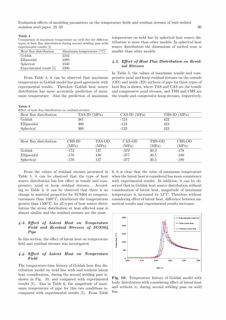
Table 4Comparison of maximum temperature on weld line for differenttypes of heat flux distribution during second welding pass withexperimental results [1].
Heat flux distribution Maximum temperature (◦C)
Goldak 2242Ellipsoidal 2289Spherical 2340Experimental result [1] 2200
From Table 4, it can be observed that maximumtemperature in Goldak model has good agreement withexperimental results. Therefore Goldak heat sourcedistribution has more accurately prediction of maxi-mum temperature. Also the prediction of maximum
temperature on weld line by spherical heat source dis-tribution is more than other models. In spherical heatsource distribution the dimensions of melted zone issmaller than other models.
4.2. Effect of Heat Flux Distribution on Resid-ual Stresses
In Table 5, the values of maximum tensile and com-pressive axial and hoop residual stresses on the outside(OD) and inside (ID) surfaces of pipe for three types ofheat flux is shown, where TAS and CAS are the tensileand compressive axial stresses, and THS and CHS arethe tensile and compressive hoop stresses, respectively.
Table 5Effect of heat flux distribution on residual stresses.
Heat flux distribution TAS-ID (MPa) CAS-ID (MPa) THS-ID (MPa)Goldak 361 -124 422Ellipsoidal 360 -124 423Spherical 360 -123 423
Heat flux distribution CHS-ID(MPa)
TAS-OD(MPa)
CAS-OD(MPa)
THS-OD(MPa)
CHS-OD(MPa)
Goldak -172 137 -379 30.2 -179Ellipsoidal -170 138 -377 30.5 -180Spherical -170 137 -377 30.5 -180
From the values of residual stresses presented inTable 5, it can be observed that the type of heatsource distribution has low effect in tensile and com-pressive, axial or hoop residual stresses. Accord-ing to Table 3, it can be observed that there is nochange in material properties for SUS304 at tempera-turesmore than 1500◦C, thereforeat the temperaturesgreater than 1500◦C, for all types of heat source distri-bution the stress distribution at heat affected zone isalmost similar and the residual stresses are the same.
4.3. Effect of Latent Heat on TemperatureField and Residual Stresses of SUS304Pipe
In this section, the effect of latent heat on temperaturefield and residual stresses was investigated.
4.4. Effect of Latent Heat on TemperatureField
The temperature-time history of Goldak heat flux dis-tribution model on weld line with and without latentheat consideration, during the second welding pass is-shown in Fig. 10, and compared with experimentalresults [1]. Also in Table 6, the magnitude of maxi-mum temperature of pipe for this two conditions is-compared with experimental results [1]. From Table
6, it is clear that the value of maximum temperaturewhen the latent heat is considered has more consistencywith experimental results. In addition, it can be ob-served that in Goldak heat source distribution withoutconsideration of latent heat, magnitude of maximumtemperature is increased by 52◦C. Therefore withoutconsidering effect of latent heat, difference between nu-merical results and experimental results increases.
Fig. 10. Temperature history of Goldak model withbody distribution with considering effect of latent heatand without it, during second welding pass on weldline.
Evaluation effects of modeling parameters on the temperature fields and residual stresses of butt-weldedstainless steel pipes: 25–33 30

Table 6Effect of latent heat on maximum temperature of weld line dur-ing second welding pass in Goldak heat flux distribution.
Maximumtemperature(◦C)
Goldak distribution with considerationthe effect of latent heat
2242
Goldak distribution without consider-ation effect of latent heat
2294
Experimental result [1] 2200
4.5. Effect of Latent Heat on Residual Stressesof SUS304 Pipe
In Table 7, the values of tensile and compressive, ax-ial and hoop residual stresses on the outside (OD) andinside (ID) surfaces of pipe for Goldak heat flux distri-bution with and without latent heat consideration areshown.
From the results of residual stresses presented inTable 7, it can be observed that the effect of latentheat on the maximum axial and hoop residual stresseson weld lineis negligible.
Table 7Effect of latent heat on residual stresses.
TAS-ID(MPa)
CAS-ID(MPa)
THS-ID(MPa)
CHS-ID(MPa)
TAS-OD(MPa)
CAS-OD(MPa)
THS-OD(MPa)
CHS-OD(MPa)
Goldak with latentheat
361 -124 422 -172 137 -379 30.2 -179
Goldak without latentheat
3607 -126 423 -171 138 -378 30.8 -179
5. Effects of Heat Flux Type on Temper-ature Field and Residual Stress
The heat input to the work piece during arc weldingcan be divided into two portions, including the heatof the welding arc, and the other is that of the meltdroplets. The heat of the welding arc was modeled bya surface heat source with a Gaussian distribution thatwas presented by Pavelic et al. [10], and the heat ofmelt droplets was modeled by a volumetric heat sourcewith uniform density presented by Goldak [9].
In this section, four types of heat flux source dis-tribution were investigated. In the first state heatflux is assumed fully-volumetric then other three stateswere assumed 20% surface-80% body, 40% surface-60%body and 90% surface-10% body.
5.1. Effect of Heat Flux Type on TemperatureField
In Fig. 11, temperature history for above four types ofheat flux source distribution is compared with exper-imental results [1] during first welding pass on insidesurface of pipe at distance 3mm from weld bead at an-gle of 180◦.
From Fig. 11, it can be observed that with de-creasing percentage of body heat flux and increasingsurface heat flux, maximum temperature has been re-duced. More over it can be concluded that by usingfully-volumetric heat source flux, the temperature his-tory has more consistency with experimental resultsthan the other heat source distribution. The maxi-mum temperature of 90% surface-10% body heat fluxdistribution decreased 36% comparing with experimen-tal results.
Fig. 11. Temperature history for four types of heatflux source distribution in comparison with experimen-tal results during first welding pass on inside surface ofpipe at distance 3mm from weld bead at angle 180◦.
5.2. Effect of Heat Flux Type on ResidualStresses
In Figs. 12-15, the axial and the hoop residual stressesdistribution on the inside and outside surfaces of pipealong the axial direction for four types of heat flux dis-tribution are compared with experimental results.
From these figures it can be observed that with de-creasing percentage of body heat flux and increasingsurface heat flux the difference between numerical sim-ulation and experimental results for predicting of hoopand axial residual stresses has been increased. Also,from Figs. 12 and 14 it is clear that specially on theweld zone, there are no important differences of axialresidual stresses with decreasing percentage of bodyheat flux and increasing surface heat flux.
Journal of Stress Analysis/ Vol. 1, No. 2/ Autumn − Winter 2016-17 31

Fig. 12. Axial residual stress distribution for fourtypes of heat flux distribution along axial distance atangle 180◦ on the inside surface of pipe.
Fig. 13. Hoop residual stress distribution for fourtypes of heat flux distribution along axial distance atangle 180 on the inside surface of pipe.
Fig. 14. Axial residual stress distribution for fourtypes of heat flux distribution along axial distance atangle 180◦ on the outside surface of pipe.
From Fig. 15, it can be seen that in the weldedzone compressive hoop residual stresses on the outside
surface changes to tensile hoop residual stresses withincreasing percentage of surface heat flux.
Fig. 15. Hoop residual stress distribution for fourtypes of heat flux distribution along axial distance atangle 180◦ on the outside surface of pipe.
6. Conclusions
In this paper, a sequentially coupled 3D thermal-mechanical FE method was developed to predict weld-ing residual stress distribution and temperature fieldduring two-pass tungsten inert gas arc welding in abutt-welded stainless steel pipe. Also the effects ofheat flux distribution, latent heat, and heat flux typeon temperature field and residual stresses were investi-gated. According to the simulated results, the follow-ing conclusions can be drawn:
1. The thermal history, axial and hoop residualstresses from FE simulations had good agreementwith available experimental results.
2. Three distributions of heat source including,Goldak, elliptical, and spherical heat source fluxwere investigated in this paper, the maximumtemperature on weld line predicted by Goldakheat source flux distribution had good consis-tency with experimental results. Also, the type ofheat source distribution had low effect in tensileand compressive axial and hoop residual stresses.
3. In simulation presented in this paper, withoutconsidering effect of latent heat the maximumtemperature on weld line would increase by 5%approximately and the difference between nu-merical results and experimental results would-increase. Also the effect of latent heat parameteron residual stress distribution was negligible.
4. The temperature history predicted by fully-volumetric heat source flux had good agreementwith experimental results. Also, with decreas-ing percentage of body heat flux and increasingsurface heat flux, the maximum temperature on
Evaluation effects of modeling parameters on the temperature fields and residual stresses of butt-weldedstainless steel pipes: 25–33 32
weld line was decreased and the difference be-tween numerical simulation and experimental re-sults for predicting of hoop and axial residualstresses increased.
5. The change of axial residual stresses along ax-ial direction with decreasing percentage of bodyheat flux and increasing surface heat flux werenegligible.
6. In the weld zone, compressive hoop residualstresses on the outside surface changed to tensilehoop residual stresses with increase in percentageof surface heat flux.
References
[1] D. Deng, H. Murakawa, Numerical simulation oftemperature field and residual stress in multi-passwelds in stainless steel pipe and comparison withexperimental measurements, Comp. Mater. Sci.,37(3) (2006) 269-277.
[2] B. Brickstad, B.L. Josefson, A parametric study ofresidual stresses in multi-pass butt-welded stainlesssteel pipes, Int. J. Pres. Ves. Pip., 75(1) (1998) 11-25.
[3] T. Tso-Liang, C. Peng-Hsiang, T. Wen-Cheng, Ef-fect of welding sequences on residual stresses, Com-put. Struct., 81 (2003) 273-286.
[4] C.H. Lee, K.H. Chang, Three-dimensional finite el-ement simulation of residual stresses in circumfer-ential welds of steel pipe including pipe diametereffects, Mat. Sci. Eng., A 487 (2008) 210-218.
[5] I. Sattari-Far, M.R. Farahani, Effect of the weldgroove shape and pass number on residual stressesin butt-welded pipes, Int. J. Pres. Ves. Pip., 86(2009) 723-731.
[6] Feli S., M. E. Aalami Aleagha, M. Foroutan, E.Borzabadi Farahani, Finite element simulation ofwelding sequences effect on residual stresses in mul-tipass butt-welded stainless steel pipes, J. Press.Vessel. Technol., 134(1) (2012) 9 011209.
[7] M. Foroutan, M. E. Aalami-Aleagha, S. Feli, S.Nikabadi, Investigation of hydrostatic pressure ef-fect on the residual stresses of circumferentiallybutt-welded steel pipes, J. Press. Vessel. Technol.,134(3) (2012) 4 034503.
[8] Dean Deng, FEM prediction of welding resid-ual stress and distortion in carbon steel consider-ing phase transformation effects, Mater. Des., 30(2009) 359-366.
[9] A. Goldak John, M. Akhlaghi, ComputationalWelding Mechanics, Springer Science, 2005.
[10] V. Pavelic, R. Tanbakuchi, O.A. Uyehara, P. S.Myers, Experimental and computed temperaturehistories in Gas Tungsten Arc Welding of thinplates, Weld. J., 48(7) (1969) 295-305.
Journal of Stress Analysis/ Vol. 1, No. 2/ Autumn − Winter 2016-17 33