Embed Size (px)
Citation preview
MA
X6
60
00
ISO/IEC 14443 Type B-Compliant64-Bit UID
________________________________________________________________ Maxim Integrated Products 1
19-5528; Rev 0; 1/11
For pricing, delivery, and ordering information, please contact Maxim Direct at 1-888-629-4642,or visit Maxim’s website at www.maxim-ic.com.
EVALUATION KIT
AVAILABLE
General DescriptionThe MAX66000 combines a 64-bit unique identifier(UID) and a 13.56MHz RF interface (ISO/IEC 14443Type B, Parts 2-4) in a single chip. The UID can beread through the block transmission protocol (ISO/IEC14443-4), where requests and responses areexchanged through I-blocks once a device is in theACTIVE state. The data rate can be as high as847.5kbps. The reader must support a frame size of 19bytes. The device supports an application family identi-fier (AFI) and a card identifier (CID). AFI and the appli-cation data field can be factory programmed withcustomer-supplied data. ISO/IEC 14443 functions notsupported are chaining, frame-waiting time extension,and power indication.
ApplicationsDriver Identification (Fleet Application)
Access Control
Asset Tracking
Features♦ Fully Compliant ISO/IEC 14443 (Parts 2-4) Type B
Interface
♦ 13.56MHz ±7kHz Carrier Frequency
♦ 64-Bit UID
♦ Supports AFI and CID Function
♦ Write: 10% ASK Modulation at 105.9kbps,211.9kbps, 423.75kbps, or 847.5kbps
♦ Read: Load Modulation Using BPSK ModulatedSubcarrier at 105.9kbps, 211.9kbps, 423.75kbps,or 847.5kbps
♦ Powered Entirely Through the RF Field
♦ Operating Temperature: -25°C to +50°C
Ordering Information
+Denotes a lead(Pb)-free/RoHS-compliant package.
PART TEMP RANGE PIN-PACKAGE
MAX66000E-000AA+ -25°C to +50°C ISO Card
MAX66000K-000AA+ -25°C to +50°C Key Fob
IC LOAD
SWITCHEDLOAD
MAGNETICCOUPLING
ANTENNARX_IN
TX_OUT
TRANSMITTER
13.56MHz READER
MAX66000
Typical Operating Circuit
Mechanical Drawings appear at end of data sheet.
MA
X6
60
00
ISO/IEC 14443 Type B-Compliant64-Bit UID
2 _______________________________________________________________________________________
Detailed DescriptionThe MAX66000 combines a 64-bit UID and a13.56MHz RF interface (ISO/IEC 14443 Type B, Parts2-4) in a single chip. The UID can be read through theISO/IEC 14443-4 block transmission protocol, whererequests and responses are exchanged through I-blocks once a device is in the ACTIVE state. The read-er must support a frame size of at least 19 bytes. Thedata rate can be as high as 847.5kbps. The MAX66000supports AFI and CID. ISO 14443 functions not sup-ported are chaining, frame-waiting time extension, andpower indication. Applications of the MAX66000include driver identification (fleet application), accesscontrol, and asset tracking.
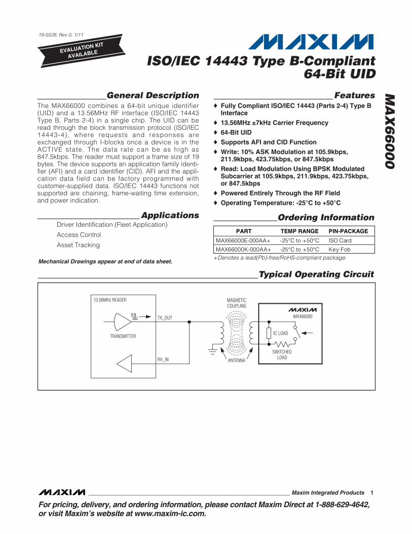
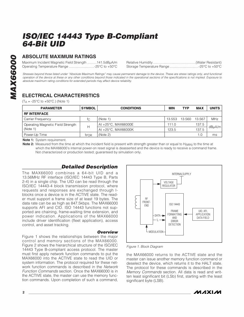
OverviewFigure 1 shows the relationships between the majorcontrol and memory sections of the MAX66000.Figure 2 shows the hierarchical structure of the ISO/IEC14443 Type B-compliant access protocol. The mastermust first apply network function commands to put theMAX66000 into the ACTIVE state to read the UID orsystem information. The protocol required for these net-work function commands is described in the NetworkFunction Commands section. Once the MAX66000 is inthe ACTIVE state, the master can use the memory func-tion commands. Upon completion of such a command,
the MAX66000 returns to the ACTIVE state and themaster can issue another memory function command ordeselect the device, which returns it to the HALT state.The protocol for these commands is described in theMemory Commands section. All data is read and writ-ten least significant bit (LSb) first, starting with the leastsignificant byte (LSB).
ABSOLUTE MAXIMUM RATINGS
ELECTRICAL CHARACTERISTICS(TA = -25°C to +50°C.) (Note 1)
Stresses beyond those listed under “Absolute Maximum Ratings” may cause permanent damage to the device. These are stress ratings only, and functionaloperation of the device at these or any other conditions beyond those indicated in the operational sections of the specifications is not implied. Exposure toabsolute maximum rating conditions for extended periods may affect device reliability.
Note 1: System requirement.Note 2: Measured from the time at which the incident field is present with strength greater than or equal to H(MIN) to the time at
which the MAX66000’s internal power-on reset signal is deasserted and the device is ready to receive a command frame.Not characterized or production tested; guaranteed by simulation only.
Maximum Incident Magnetic Field Strength ..........141.5dBµA/mOperating Temperature Range ...........................-25°C to +50°C
Relative Humidity ..............................................(Water Resistant)Storage Temperature Range ...............................-25°C to +50°C
PARAMETER SYMBOL CONDITIONS MIN TYP MAX UNITS
RF INTERFACE
Carrier Frequency fC (Note 1) 13.553 13.560 13.567 MHz
At +25°C, MAX66000E 111.0 137.5 Operating Magnetic Field Strength (Note 1)
HAt +25°C, MAX66000K 123.5 137.5
dBμA/m
Power-Up Time tPOR (Note 2) 1.0 ms
RFFRONT-
END
VOLTAGEREGULATOR
INTERNALSUPPLY
UID, AFI,APPLICATIONDATA FIELD
ISO 14443
FRAMEFORMATTING
ANDERROR
DETECTION
fc
DATA
MODULATION
Figure 1. Block Diagram
MA
X6
60
00
ISO/IEC 14443 Type B-Compliant64-Bit UID
_______________________________________________________________________________________ 3
Parasite PowerAs a wireless device, the MAX66000 is not connectedto any power source. It gets the energy for operationfrom the surrounding RF field, which needs to have aminimum strength as specified in the ElectricalCharacteristics table.
Unique Identification Number (UID)Each MAX66000 contains a factory-programmed andlocked identification number that is 64 bits long(Figure 3). The lower 36 bits are the serial number of thechip. The next 8 bits store the device feature code,which is 01h. Bits 45 to 48 are 0h. The code in bit loca-tions 49 to 56 identifies the chip manufacturer accordingto ISO/IEC 7816-6/AM1. This code is 2Bh for Maxim.The code in the upper 8 bits is E0h. The UID is readaccessible through the Get UID and Get SystemInformation commands. The lower 32 bits of the UID aretransmitted in the PUPI field of the ATQB response tothe REQB, WUPB, or SLOT-MARKER command. Theupper 32 bits of the UID are factory programmed into
the application data field, which is transmitted as part ofthe ATQB response. This way the master receives thecomplete UID in the first response from the slave. Seethe Network Function Commands section for details.
ISO/IEC 14443 Type BCommunication Concept
The communication between the master and theMAX66000 (slave) is based on the exchange of datapackets. The master initiates every transaction; onlyone side (master or slaves) transmits information at anytime. Data packets are composed of characters, whichalways begin with a START bit and typically end withone or more STOP bits (Figure 4). The least significantdata bit is transmitted first. Data characters have 8 bits.Each data packet begins with a start-of-frame (SOF)character and ends with an end-of-frame (EOF) charac-ter. The EOF/SOF characters have 9 all-zero data bits(Figure 5). The SOF has 2 STOP bits, after which datacharacters are transmitted. A data packet with at least
AVAILABLE COMMANDS: DATA FIELD AFFECTED:
REQUEST (REQB)WAKEUP (WUPB)SLOT-MARKERHALT (HLTB)SELECT (ATTRIB)DESELECT (DESELECT)
AFI, ADMINISTRATIVE DATAAFI, ADMINISTRATIVE DATA(ADMINISTRATIVE DATA)PUPIPUPI, ADMINISTRATIVE DATA(ADMINISTRATIVE DATA)
NETWORKFUNCTION COMMANDS
GET SYSTEM INFORMATIONGET UID
64-BIT UID, AFI, CONSTANTS64-BIT UID
MEMORY FUNCTIONCOMMANDS
COMMAND LEVEL:
MAX66000
Figure 2. Hierarchical Structure of ISO/IEC 14443 Type B Protocol
MSb LSb
64 57 56 49 48 45 44 37 36 1
E0h 2Bh 0h FEATURE CODE (01h) 36-BIT IC SERIAL NUMBER
Figure 3. 64-Bit UID
START10 BIT 1 BIT 2 BIT 3 BIT 4 BIT 5 BIT 6 BIT 7 BIT 8
LSb MSb
STOP
Figure 4. ISO/IEC 14443 Data Character Format
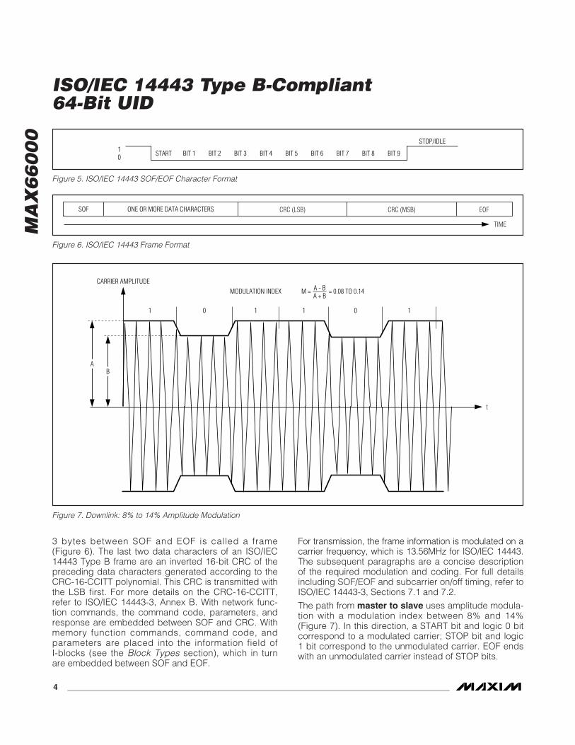
3 bytes between SOF and EOF is called a frame(Figure 6). The last two data characters of an ISO/IEC14443 Type B frame are an inverted 16-bit CRC of thepreceding data characters generated according to theCRC-16-CCITT polynomial. This CRC is transmitted withthe LSB first. For more details on the CRC-16-CCITT,refer to ISO/IEC 14443-3, Annex B. With network func-tion commands, the command code, parameters, andresponse are embedded between SOF and CRC. Withmemory function commands, command code, andparameters are placed into the information field ofI-blocks (see the Block Types section), which in turnare embedded between SOF and EOF.
For transmission, the frame information is modulated on acarrier frequency, which is 13.56MHz for ISO/IEC 14443.The subsequent paragraphs are a concise descriptionof the required modulation and coding. For full detailsincluding SOF/EOF and subcarrier on/off timing, refer toISO/IEC 14443-3, Sections 7.1 and 7.2.
The path from master to slave uses amplitude modula-tion with a modulation index between 8% and 14%(Figure 7). In this direction, a START bit and logic 0 bitcorrespond to a modulated carrier; STOP bit and logic1 bit correspond to the unmodulated carrier. EOF endswith an unmodulated carrier instead of STOP bits.
MA
X6
60
00
ISO/IEC 14443 Type B-Compliant64-Bit UID
4 _______________________________________________________________________________________
START10 BIT 1 BIT 2 BIT 3 BIT 4 BIT 5 BIT 6 BIT 7 BIT 9
STOP/IDLE
BIT 8
Figure 5. ISO/IEC 14443 SOF/EOF Character Format
SOF ONE OR MORE DATA CHARACTERS CRC (LSB) CRC (MSB) EOF
TIME
Figure 6. ISO/IEC 14443 Frame Format
AB
CARRIER AMPLITUDE
t
1 1 110 0
MODULATION INDEX M = = 0.08 TO 0.14A - BA + B
Figure 7. Downlink: 8% to 14% Amplitude Modulation
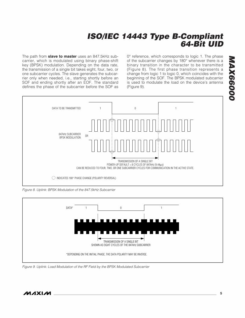
The path from slave to master uses an 847.5kHz sub-carrier, which is modulated using binary phase-shiftkey (BPSK) modulation. Depending on the data rate,the transmission of a single bit takes eight, four, two, orone subcarrier cycles. The slave generates the subcar-rier only when needed, i.e., starting shortly before anSOF and ending shortly after an EOF. The standarddefines the phase of the subcarrier before the SOF as
0° reference, which corresponds to logic 1. The phaseof the subcarrier changes by 180° whenever there is abinary transition in the character to be transmitted(Figure 8). The first phase transition represents achange from logic 1 to logic 0, which coincides with thebeginning of the SOF. The BPSK modulated subcarrieris used to modulate the load on the device’s antenna(Figure 9).
MA
X6
60
00
ISO/IEC 14443 Type B-Compliant64-Bit UID
_______________________________________________________________________________________ 5
DATA TO BE TRANSMITTED
INDICATES 180° PHASE CHANGE (POLARITY REVERSAL)
OR
1 10
847kHz SUBCARRIERBPSK MODULATION
TRANSMISSION OF A SINGLE BITPOWER-UP DEFAULT = 8 CYCLES OF 847kHz (9.44μs)
CAN BE REDUCED TO FOUR, TWO, OR ONE SUBCARRIER CYCLES FOR COMMUNICATION IN THE ACTIVE STATE.
Figure 8. Uplink: BPSK Modulation of the 847.5kHz Subcarrier
TRANSMISSION OF A SINGLE BITSHOWN AS EIGHT CYCLES OF THE 847kHz SUBCARRIER
DATA*
*DEPENDING ON THE INITIAL PHASE, THE DATA POLARITY MAY BE INVERSE.
1 0 1
Figure 9. Uplink: Load Modulation of the RF Field by the BPSK Modulated Subcarrier
MA
X6
60
00
ISO/IEC 14443 BlockTransmission Protocol
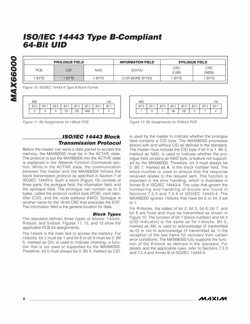
Before the master can send a data packet to access thememory, the MAX66000 must be in the ACTIVE state.The protocol to put the MAX66000 into the ACTIVE stateis explained in the Network Function Commands sec-tion. While in the ACTIVE state, the communicationbetween the master and the MAX66000 follows theblock transmission protocol as specified in Section 7 ofISO/IEC 14443-4. Such a block (Figure 10) consists ofthree parts: the prologue field, the information field, andthe epilogue field. The prologue can contain up to 3bytes, called the protocol control byte (PCB), card iden-tifier (CID), and the node address (NAD). Epilogue isanother name for the 16-bit CRC that precedes the EOF.The information field is the general location for data.
Block TypesThe standard defines three types of blocks: I-block,R-block, and S-block. Figures 11, 12, and 13 show theapplicable PCB bit assignments.
The I-block is the main tool to access the memory. ForI-blocks, bit 2 must be 1 and bit 6 to bit 8 must be 0. Bit5, marked as CH, is used to indicate chaining, a func-tion that is not used or supported by the MAX66000.Therefore, bit 5 must always be 0. Bit 4, marked as CID,
is used by the master to indicate whether the prologuefield contains a CID byte. The MAX66000 processesblocks with and without CID as defined in the standard.The master must include the CID byte if bit 4 is 1. Bit 3,marked as NAD, is used to indicate whether the pro-logue field contains an NAD byte, a feature not support-ed by the MAX66000. Therefore, bit 3 must always be0. Bit 1, marked as #, is the block number field. Theblock number is used to ensure that the responsereceived relates to the request sent. This function isimportant in the error handling, which is illustrated inAnnex B of ISO/IEC 14443-4. The rules that govern thenumbering and handling of blocks are found inSections 7.5.3 and 7.5.4 of ISO/IEC 14443-4. TheMAX66000 ignores I-blocks that have bit 5 or bit 3 setto 1.
For R-blocks, the states of bit 2, bit 3, bit 6, bit 7, andbit 8 are fixed and must be transmitted as shown inFigure 12. The function of bit 1 (block number) and bit 4(CID indicator) is the same as for I-blocks. Bit 5,marked as AN, is used to acknowledge (if transmittedas 0) or not to acknowledge (if transmitted as 1) thereception of the last frame for recovery from certainerror conditions. The MAX66000 fully supports the func-tion of the R-block as defined in the standard. Fordetails and the applicable rules, refer to Sections 7.5.3and 7.5.4 and Annex B of ISO/IEC 14443-4.
ISO/IEC 14443 Type B-Compliant64-Bit UID
6 _______________________________________________________________________________________
PROLOGUE FIELD INFORMATION FIELD EPILOGUE FIELD
PCB CID NAD (DATA) CRC (LSB)
CRC (MSB)
1 BYTE 1 BYTE 1 BYTE 0 OR MORE BYTES 1 BYTE 1 BYTE
Figure 10. ISO/IEC 14443-4 Type B Block Format
BIT 8 BIT 7 BIT 6 BIT 5 BIT 4 BIT 3 BIT 2 BIT 1MSb LSb
0 0 0 CH CID NAD 1 #
Figure 11. Bit Assignments for I-Block PCB
BIT 8 BIT 7 BIT 6 BIT 5 BIT 4 BIT 3 BIT 2 BIT 1MSb LSb
1 0 1 AN CID 0 1 #
Figure 12. Bit Assignments for R-Block PCB
For S-blocks, the states of bit 1, bit 2, bit 3, and bit 7and bit 8 are fixed and must be transmitted as shown inFigure 13. The function of bit 4 (CID indicator) is thesame as for I-blocks. Bit 5 and bit 6, when 00b, specifywhether the S-block represents a DESELECT command.If bit 5 and bit 6 are 11b, the S-block represents aframe-waiting time extension (WTX) request, a feature totell the master that the response is going to take longerthan specified by the frame waiting time (FWT) (see theATQB Response section). However, the MAX66000does not use this feature, and, consequently, the onlyuse of the S-block is to transition the device from theACTIVE state to the HALT state using the DESELECTcommand (see the Network Function Commands section).
Card IdentifierFigure 14 shows the bit assignment within the cardidentifier byte. The purpose of bits 4 to 1 is to selectone of multiple slave devices that the master has ele-vated to the ACTIVE state. The CID is assigned to aslave through Param 4 of the ATTRIB command (seethe Network Function Commands section). While in theACTIVE state, a compliant slave only processes blocksthat contain a matching CID and blocks without a CID ifthe assigned CID is all zeros. If the master includes a
CID, then the slave’s response also includes a CIDbyte. Blocks with a nonmatching CIDs are ignored.
According to the standard, the slave can use bits 8 and7 to inform the master whether power-level indication issupported, and, if yes, whether sufficient power is avail-able for full functionality. Since the MAX66000 does notsupport power-level indication, the power-level bits arealways 00b. When the master transmits a CID byte, thepower-level bits must be 00b.
Information FieldSince the MAX66000 does not generate WTX requests,the information field (Figure 10) is found only with I-blocks. The length of the information field is calculatedby counting the number of bytes of the whole blockminus the length of the prologue and epilogue field.The ISO/IEC 14443 standard does not define any rulesfor the contents of the information field. The MAX66000assumes that the first byte it receives in the informationfield is a command code followed by 0 or more com-mand-specific parameters. When responding to anI-block, the first byte of the information field indicatessuccess (code 00h) followed by command-specificdata or failure (code 01h) followed by one error code.
Memory Function CommandsThe commands described in this section are transmit-ted using the block transmission protocol. The data of ablock (from prologue to epilogue) is embeddedbetween SOF and EOF, as shown in Figure 15. The CIDfield (shaded) is optional. If the request contains a CID,the response also contains a CID.
The command descriptions in this section only showthe information field of the I-blocks used to transmitrequests and responses. Since the MAX66000 neithersupports chaining nor generates WTX requests, when itreceives an I-block, the MAX66000 responds with anI-block. The block number in the I-block response is thesame as in the I-block request.
Error IndicationIn case of an error, the response to a request beginswith a 01h byte followed by one error code.
If there was no error, the information field of theresponse begins with 00h followed by command-spe-cific data, as specified in the detailed commanddescription. If the MAX66000 does not recognize acommand, it does not generate a response.
MA
X6
60
00
ISO/IEC 14443 Type B-Compliant64-Bit UID
_______________________________________________________________________________________ 7
BIT 8 BIT 7 BIT 6 BIT 5 BIT 4 BIT 3 BIT 2 BIT 1MSb LSb
1 1 CID 0 1 0
Figure 13. Bit Assignments for S-Block PCB
BIT 8 BIT 7 BIT 6 BIT 5 BIT 4 BIT 3 BIT 2 BIT 1MSb LSb
0 0 0 0
(POWER LEVEL) (FIXED) CARD IDENTIFIER VALUE
Figure 14. Bit Assignments for CID Byte in I-Blocks
PCB CIDSOF INFORMATION FIELD CRC (MSB)CRC (LSB) EOF
Figure 15. Frame Format for Block Transmission Protocol
INDICATOR UID
00h (8 Bytes)
Response Information Field for the Get UID Command (No Error)
MA
X6
60
00
ISO/IEC 14443 Type B-Compliant64-Bit UID
8 _______________________________________________________________________________________
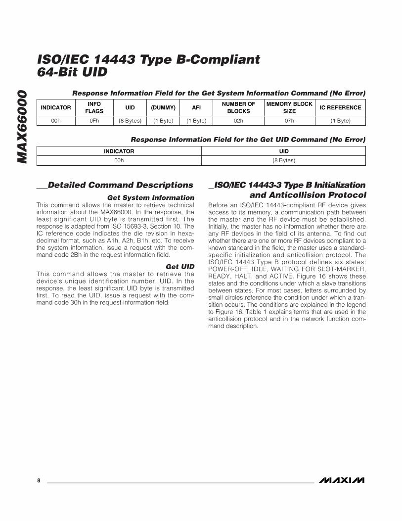
Detailed Command DescriptionsGet System Information
This command allows the master to retrieve technicalinformation about the MAX66000. In the response, theleast significant UID byte is transmitted first. Theresponse is adapted from ISO 15693-3, Section 10. TheIC reference code indicates the die revision in hexa-decimal format, such as A1h, A2h, B1h, etc. To receivethe system information, issue a request with the com-mand code 2Bh in the request information field.
Get UIDThis command allows the master to retrieve thedevice’s unique identification number, UID. In theresponse, the least significant UID byte is transmittedfirst. To read the UID, issue a request with the com-mand code 30h in the request information field.
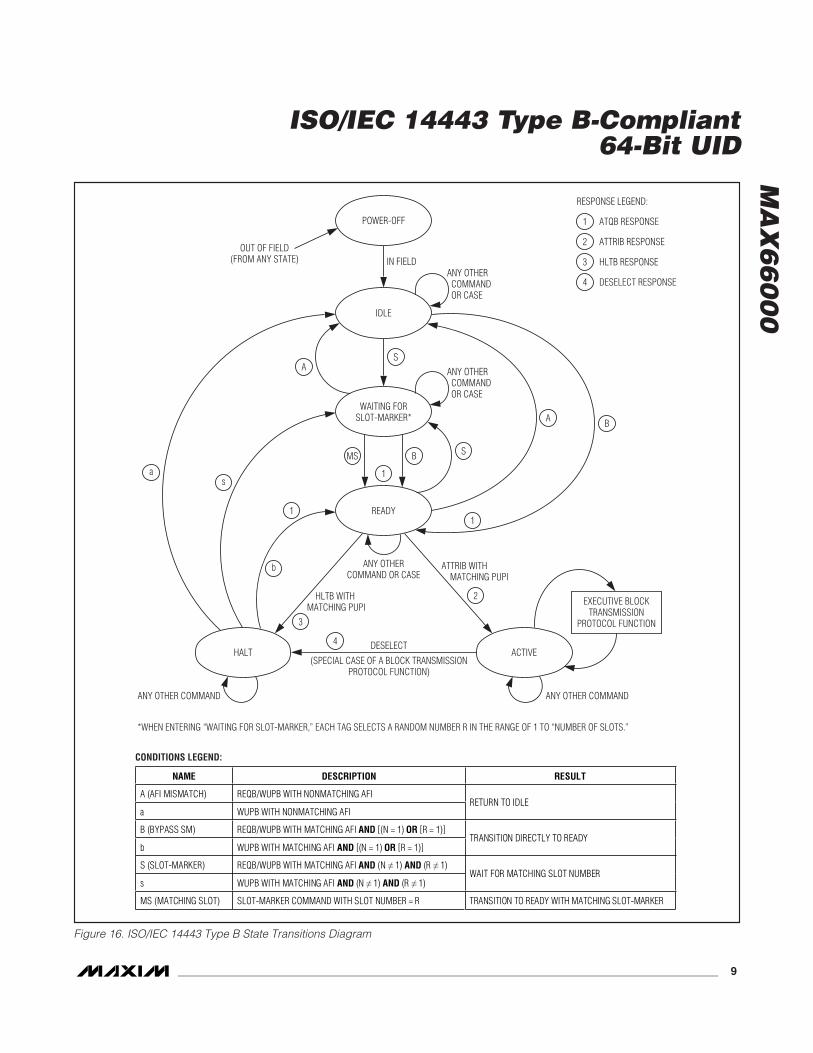
ISO/IEC 14443-3 Type B Initializationand Anticollision Protocol
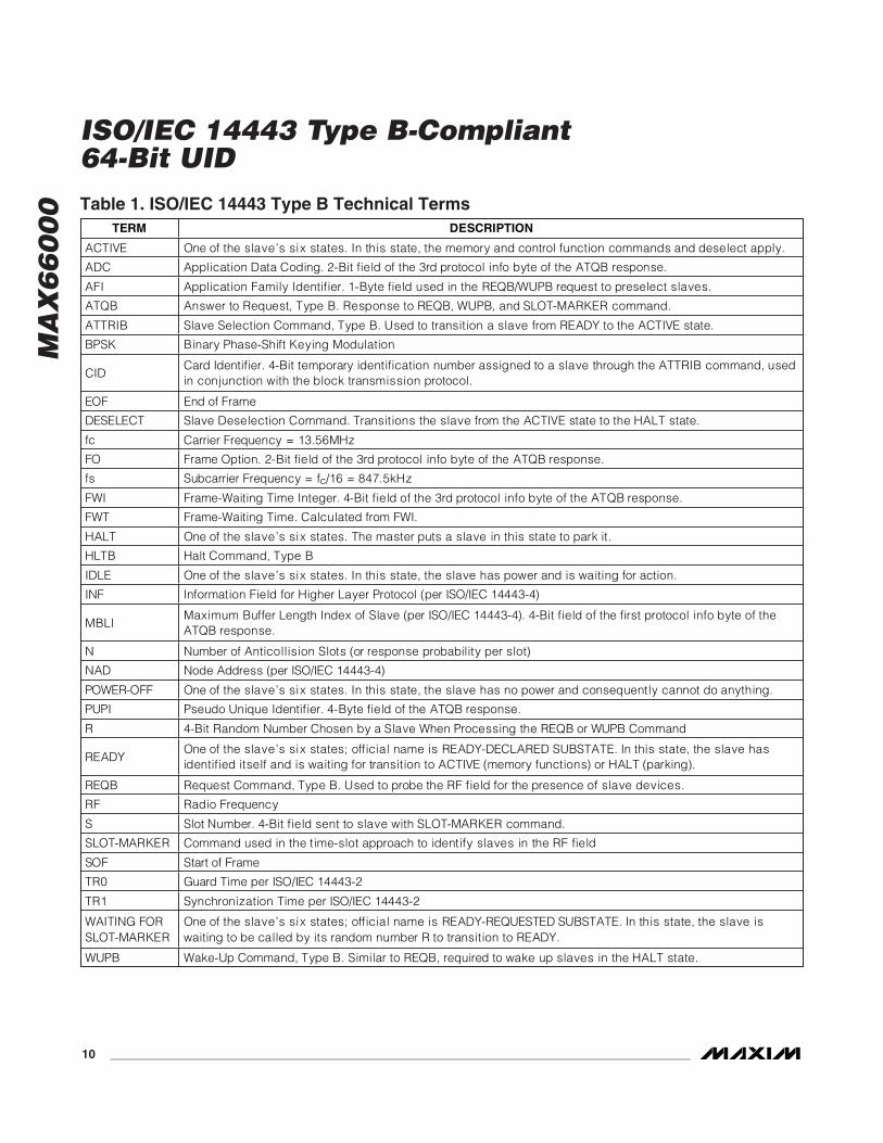
Before an ISO/IEC 14443-compliant RF device givesaccess to its memory, a communication path betweenthe master and the RF device must be established.Initially, the master has no information whether there areany RF devices in the field of its antenna. To find outwhether there are one or more RF devices compliant to aknown standard in the field, the master uses a standard-specific initialization and anticollision protocol. TheISO/IEC 14443 Type B protocol defines six states:POWER-OFF, IDLE, WAITING FOR SLOT-MARKER,READY, HALT, and ACTIVE. Figure 16 shows thesestates and the conditions under which a slave transitionsbetween states. For most cases, letters surrounded bysmall circles reference the condition under which a tran-sition occurs. The conditions are explained in the legendto Figure 16. Table 1 explains terms that are used in theanticollision protocol and in the network function com-mand description.
INDICATORINFO
FLAGSUID (DUMMY) AFI
NUMBER OF BLOCKS
MEMORY BLOCK SIZE
IC REFERENCE
00h 0Fh (8 Bytes) (1 Byte) (1 Byte) 02h 07h (1 Byte)
Response Information Field for the Get System Information Command (No Error)
MA
X6
60
00IDLE
READY
POWER-OFF
WAITING FORSLOT-MARKER*
ACTIVEHALT
ANY OTHER COMMAND
IN FIELDANY OTHER COMMAND OR CASE
OUT OF FIELD(FROM ANY STATE)
ANY OTHER COMMAND
RESPONSE LEGEND:
*WHEN ENTERING “WAITING FOR SLOT-MARKER,” EACH TAG SELECTS A RANDOM NUMBER R IN THE RANGE OF 1 TO “NUMBER OF SLOTS.”
DESELECT
(SPECIAL CASE OF A BLOCK TRANSMISSIONPROTOCOL FUNCTION)
ATQB RESPONSE1
A
a
b
s
A B
S
SBMS
1
11
4
3
2
ATTRIB RESPONSE2
HLTB RESPONSE3
DESELECT RESPONSE4
ANY OTHER COMMAND OR CASE
ANY OTHERCOMMAND OR CASE
ATTRIB WITH MATCHING PUPI
HLTB WITHMATCHING PUPI
EXECUTIVE BLOCKTRANSMISSION
PROTOCOL FUNCTION
Figure 16. ISO/IEC 14443 Type B State Transitions Diagram
NAME DESCRIPTION RESULT
A (AFI MISMATCH) REQB/WUPB WITH NONMATCHING AFI
a WUPB WITH NONMATCHING AFI RETURN TO IDLE
B (BYPASS SM) REQB/WUPB WITH MATCHING AFI AND [(N = 1) OR [R = 1)]
b WUPB WITH MATCHING AFI AND [(N = 1) OR [R = 1)] TRANSITION DIRECTLY TO READY
S (SLOT-MARKER) REQB/WUPB WITH MATCHING AFI AND (N 1) AND (R 1)
s WUPB WITH MATCHING AFI AND (N 1) AND (R 1) WAIT FOR MATCHING SLOT NUMBER
MS (MATCHING SLOT) SLOT-MARKER COMMAND WITH SLOT NUMBER = R TRANSITION TO READY WITH MATCHING SLOT-MARKER
CONDITIONS LEGEND:
ISO/IEC 14443 Type B-Compliant64-Bit UID
_______________________________________________________________________________________ 9
MA
X6
60
00
ISO/IEC 14443 Type B-Compliant64-Bit UID
10 ______________________________________________________________________________________
TERM DESCRIPTION
ACTIVE One of the slave’s six states. In this state, the memory and control function commands and deselect apply.
ADC Application Data Coding. 2-Bit field of the 3rd protocol info byte of the ATQB response.
AFI Application Family Identifier. 1-Byte field used in the REQB/WUPB request to preselect slaves.
ATQB Answer to Request, Type B. Response to REQB, WUPB, and SLOT-MARKER command.
ATTRIB Slave Selection Command, Type B. Used to transition a slave from READY to the ACTIVE state.
BPSK Binary Phase-Shift Keying Modulation
CIDCard Identifier. 4-Bit temporary identification number assigned to a slave through the ATTRIB command, used in conjunction with the block transmission protocol.
EOF End of Frame
DESELECT Slave Deselection Command. Transitions the slave from the ACTIVE state to the HALT state.
fc Carrier Frequency = 13.56MHz
FO Frame Option. 2-Bit field of the 3rd protocol info byte of the ATQB response.
fs Subcarrier Frequency = fc/16 = 847.5kHz
FWI Frame-Waiting Time Integer. 4-Bit field of the 3rd protocol info byte of the ATQB response.
FWT Frame-Waiting Time. Calculated from FWI.
HALT One of the slave’s six states. The master puts a slave in this state to park it.
HLTB Halt Command, Type B
IDLE One of the slave’s six states. In this state, the slave has power and is waiting for action.
INF Information Field for Higher Layer Protocol (per ISO/IEC 14443-4)
MBLI Maximum Buffer Length Index of Slave (per ISO/IEC 14443-4). 4-Bit field of the first protocol info byte of the ATQB response.
N Number of Anticollision Slots (or response probability per slot)
NAD Node Address (per ISO/IEC 14443-4)
POWER-OFF One of the slave’s six states. In this state, the slave has no power and consequently cannot do anything.
PUPI Pseudo Unique Identifier. 4-Byte field of the ATQB response.
R 4-Bit Random Number Chosen by a Slave When Processing the REQB or WUPB Command
READY One of the slave’s six states; official name is READY-DECLARED SUBSTATE. In this state, the slave has identified itself and is waiting for transition to ACTIVE (memory functions) or HALT (parking).
REQB Request Command, Type B. Used to probe the RF field for the presence of slave devices.
RF Radio Frequency
S Slot Number. 4-Bit field sent to slave with SLOT-MARKER command.
SLOT-MARKER Command used in the time-slot approach to identify slaves in the RF field
SOF Start of Frame
TR0 Guard Time per ISO/IEC 14443-2
TR1 Synchronization Time per ISO/IEC 14443-2
WAITING FOR SLOT-MARKER
One of the slave’s six states; official name is READY-REQUESTED SUBSTATE. In this state, the slave is waiting to be called by its random number R to transition to READY.
WUPB Wake-Up Command, Type B. Similar to REQB, required to wake up slaves in the HALT state.
Table 1. ISO/IEC 14443 Type B Technical Terms
MA
X6
60
00
ISO/IEC 14443 Type B-Compliant64-Bit UID
______________________________________________________________________________________ 11
ISO/IEC 14443 Type B States andTransitions
POWER-OFF StateThis state applies if the slave is outside the master’s RFfield. A slave transitions to the POWER-OFF state whenleaving the power-delivering RF field. When enteringthe RF field, the slave automatically transitions to theIDLE state.
IDLE StateThe purpose of the IDLE state is to have the slave pop-ulation ready to participate in the anticollision protocol.When transitioning to the IDLE state, the slave does notgenerate any response. To maintain this state, the slavemust continuously receive sufficient power from themaster’s RF field to prevent transitioning into thePOWER-OFF state. While in the IDLE state, the slave lis-tens to the commands that the master sends, but reactsonly on the REQB and WUPB commands, provided thatthey include a matching AFI value. If the master sendsa command with a nonmatching AFI byte (conditions Aand a), a transition to IDLE is also possible from theHALT state, the READY state, and the WAITING FORSLOT-MARKER state. From IDLE, a slave can transitionto the higher states READY (condition B) or WAITINGFOR SLOT-MARKER (condition S). For details, see theREQB/WUPB command description in the NetworkFunction Commands section.
WAITING FOR SLOT-MARKER State (READY REQUESTED SUBSTATE)
The WAITING FOR SLOT-MARKER state is used in thetime-slot anticollision approach. A slave can transitionto WAITING FOR SLOT-MARKER from the IDLE, HALT,or READY state upon receiving a REQB or WUPB com-mand with a matching AFI (conditions S and s), provid-ed that both the number of slots specified in theREQB/WUPB command and the random number thatthe slave has chosen are different from 1. To maintainthis state, the slave must continuously receive sufficientpower from the master’s RF field to prevent transitioninginto the POWER-OFF state. A slave in the WAITINGFOR SLOT-MARKER state listens to the commands thatthe master sends, but reacts only on the REQB, WUPB,and SLOT-MARKER commands. From WAITING FORSLOT-MARKER, a slave can transition to the higherstate READY under condition B (bypassing the SLOT-MARKER), or MS (matching slot, SLOT-MARKER com-mand with a slot number that matches the randomnumber R). Condition A (AFI mismatch) returns theslave to the IDLE state.
READY State (READY DECLARED SUBSTATE)The READY state applies to a slave that has met the cri-teria in the anticollision protocol to send an ATQBresponse. A slave can transition to READY from IDLE orHALT (conditions B and b) or from WAITING FORSLOT-MARKER (conditions B and MS). When transition-ing to the READY state, the slave transmits an ATQBresponse. To maintain this state, the slave must contin-uously receive sufficient power from the master’s RFfield to prevent transitioning into the POWER-OFF state.A slave in the READY state listens to the commandsthat the master sends, but reacts only on the REQB,WUPB, ATTRIB, and HLTB commands. From READY, aslave can transition to ACTIVE (ATTRIB command withmatching PUPI), HALT (HLTB command with matchingPUPI), or IDLE (condition A).
HALT StateThe HALT state is used to silence slaves that havebeen identified and shall no longer participate in theanticollion protocol. This state is also used to parkslaves after communication in the ACTIVE state wascompleted. A slave transitions to the HALT state eitherfrom READY (HLTB command with matching PUPI) orfrom ACTIVE (DESELECT command with matchingCID). When transitioning to the HALT state, the slavetransmits a response that confirms the transition. Tomaintain this state, the slave must continuously receivesufficient power from the master’s RF field to preventtransitioning into the POWER-OFF state. The normalway out of the HALT state is through the WUPB com-mand. From HALT, a slave can transition to IDLE (con-dition a), READY (condition b), or WAITING FORSLOT-MARKER (condition s).
ACTIVE StateThe ACTIVE state enables the slave to process com-mands sent through the block transmission protocol.When entering the ACTIVE state, the slave confirms thetransition with a response. The only way for a slave totransition to the ACTIVE state is from the READY state(ATTRIB command with a matching PUPI). In theATTRIB command, the master assigns a 4-bit CID thatis used to address one of multiple slaves that could allbe in the ACTIVE state. To maintain this state, the slavemust continuously receive sufficient power from themaster’s RF field to prevent transitioning into thePOWER-OFF state. The normal way out of the ACTIVEstate is through the DESELECT command, which transi-tions the slave to the HALT state.
MA
X6
60
00
ISO/IEC 14443 Type B-Compliant64-Bit UID
12 ______________________________________________________________________________________
Network Function CommandsTo transition slaves devices between states, theISO/IEC 14443 Type B standard defines six networkfunction commands, called REQB, WUPB, SLOT-MARKER, HLTB, ATTRIB, and DESELECT. The masterissues the commands in the form of request frames andthe slaves respond by transmitting response frames.With network function commands, command code,parameters and response are embedded between SOFand CRC. This section describes the format of theresponse and request frames and the coding of thedata fields inside the frames as detailed as necessaryto operate the MAX66000. Not all of the fields andcases that the standard defines are relevant for theMAX66000. For a full description of those fields refer tothe ISO/IEC 14443-3, Section 7.
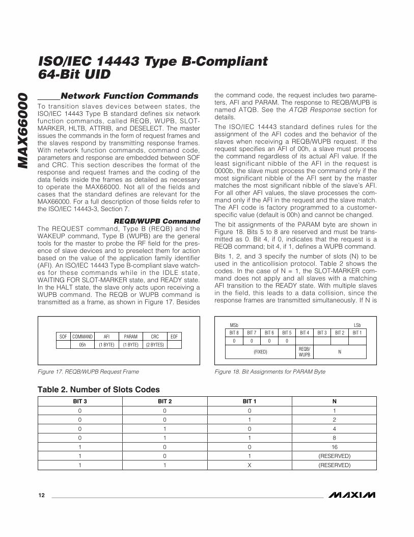
REQB/WUPB CommandThe REQUEST command, Type B (REQB) and theWAKEUP command, Type B (WUPB) are the generaltools for the master to probe the RF field for the pres-ence of slave devices and to preselect them for actionbased on the value of the application family identifier(AFI). An ISO/IEC 14443 Type B-compliant slave watch-es for these commands while in the IDLE state,WAITING FOR SLOT-MARKER state, and READY state.In the HALT state, the slave only acts upon receiving aWUPB command. The REQB or WUPB command istransmitted as a frame, as shown in Figure 17. Besides
the command code, the request includes two parame-ters, AFI and PARAM. The response to REQB/WUPB isnamed ATQB. See the ATQB Response section fordetails.
The ISO/IEC 14443 standard defines rules for theassignment of the AFI codes and the behavior of theslaves when receiving a REQB/WUPB request. If therequest specifies an AFI of 00h, a slave must processthe command regardless of its actual AFI value. If theleast significant nibble of the AFI in the request is0000b, the slave must process the command only if themost significant nibble of the AFI sent by the mastermatches the most significant nibble of the slave’s AFI.For all other AFI values, the slave processes the com-mand only if the AFI in the request and the slave match.The AFI code is factory programmed to a customer-specific value (default is 00h) and cannot be changed.
The bit assignments of the PARAM byte are shown inFigure 18. Bits 5 to 8 are reserved and must be trans-mitted as 0. Bit 4, if 0, indicates that the request is aREQB command; bit 4, if 1, defines a WUPB command.
Bits 1, 2, and 3 specify the number of slots (N) to beused in the anticollision protocol. Table 2 shows thecodes. In the case of N = 1, the SLOT-MARKER com-mand does not apply and all slaves with a matchingAFI transition to the READY state. With multiple slavesin the field, this leads to a data collision, since theresponse frames are transmitted simultaneously. If N is
COMMANDSOF AFI CRCPARAM EOF
05h (1 BYTE) (2 BYTES)(1 BYTE)
Figure 17. REQB/WUPB Request Frame
BIT 8 BIT 7 BIT 6 BIT 5 BIT 4
REQB/WUPB
BIT 3 BIT 2 BIT 1MSb LSb
0 0 0 0
(FIXED) N
Figure 18. Bit Assignments for PARAM Byte
BIT 3 BIT 2 BIT 1 N
0 0 0 1
0 0 1 2
0 1 0 4
0 1 1 8
1 0 0 16
1 0 1 (RESERVED)
1 1 X (RESERVED)
Table 2. Number of Slots Codes
MA
X6
60
00
ISO/IEC 14443 Type B-Compliant64-Bit UID
______________________________________________________________________________________ 13
larger than 1, each slave in the field selects its own4-bit random number, R, in the range of 1 to N. A slavethat happens to choose R = 1 responds to theREQB/WUPB request. The larger N is the lower theprobability of colliding response frames; however, if Nis 16 and there is only a single slave in the field, it cantake up to 15 SLOT-MARKER commands to get aresponse. The method to identify all slaves in the fieldrelying solely on the random number R and theREQB/WUPB command is called the “probabilisticapproach.” For mode information about the anticollisionprocess, see the Anticollision Examples section.
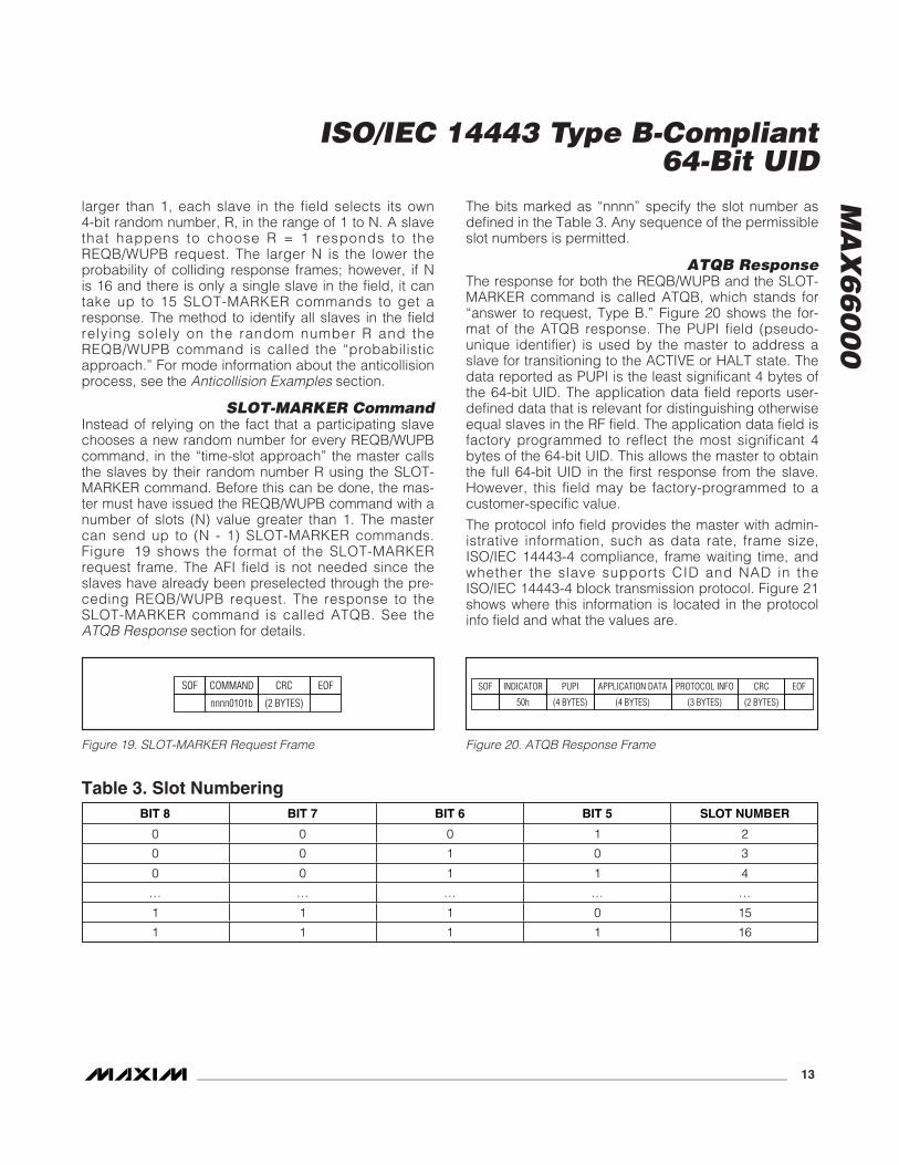
SLOT-MARKER CommandInstead of relying on the fact that a participating slavechooses a new random number for every REQB/WUPBcommand, in the “time-slot approach” the master callsthe slaves by their random number R using the SLOT-MARKER command. Before this can be done, the mas-ter must have issued the REQB/WUPB command with anumber of slots (N) value greater than 1. The mastercan send up to (N - 1) SLOT-MARKER commands.Figure 19 shows the format of the SLOT-MARKERrequest frame. The AFI field is not needed since theslaves have already been preselected through the pre-ceding REQB/WUPB request. The response to theSLOT-MARKER command is called ATQB. See theATQB Response section for details.
The bits marked as “nnnn” specify the slot number asdefined in the Table 3. Any sequence of the permissibleslot numbers is permitted.
ATQB ResponseThe response for both the REQB/WUPB and the SLOT-MARKER command is called ATQB, which stands for“answer to request, Type B.” Figure 20 shows the for-mat of the ATQB response. The PUPI field (pseudo-unique identifier) is used by the master to address aslave for transitioning to the ACTIVE or HALT state. Thedata reported as PUPI is the least significant 4 bytes ofthe 64-bit UID. The application data field reports user-defined data that is relevant for distinguishing otherwiseequal slaves in the RF field. The application data field isfactory programmed to reflect the most significant 4bytes of the 64-bit UID. This allows the master to obtainthe full 64-bit UID in the first response from the slave.However, this field may be factory-programmed to acustomer-specific value.
The protocol info field provides the master with admin-istrative information, such as data rate, frame size,ISO/IEC 14443-4 compliance, frame waiting time, andwhether the slave supports CID and NAD in theISO/IEC 14443-4 block transmission protocol. Figure 21shows where this information is located in the protocolinfo field and what the values are.
COMMANDSOF CRC EOF
nnnn0101b (2 BYTES)
Figure 19. SLOT-MARKER Request Frame
INDICATORSOF CRC EOF
50h
APPLICATION DATA
(4 BYTES) (2 BYTES)
PROTOCOL INFO
(3 BYTES)
PUPI
(4 BYTES)
Figure 20. ATQB Response Frame
BIT 8 BIT 7 BIT 6 BIT 5 SLOT NUMBER
0 0 0 1 2
0 0 1 0 3
0 0 1 1 4
… … … … …
1 1 1 0 15
1 1 1 1 16
Table 3. Slot Numbering
MA
X6
60
00
ISO/IEC 14443 Type B-Compliant64-Bit UID
14 ______________________________________________________________________________________
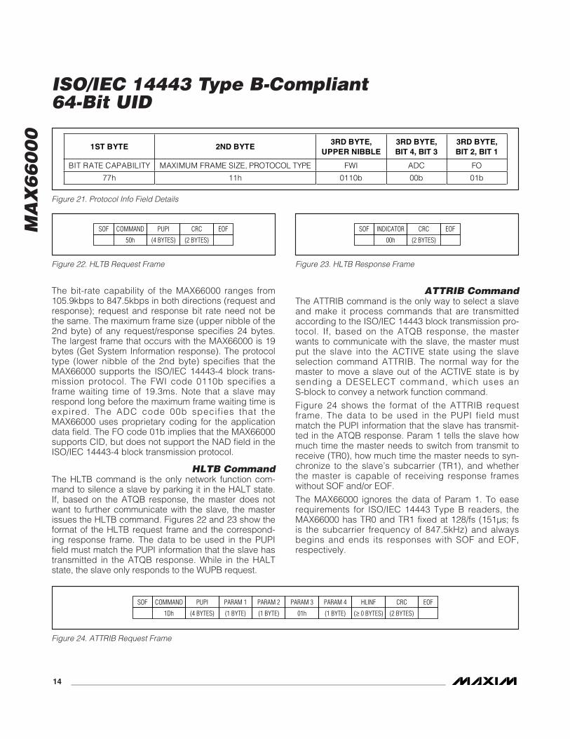
The bit-rate capability of the MAX66000 ranges from105.9kbps to 847.5kbps in both directions (request andresponse); request and response bit rate need not bethe same. The maximum frame size (upper nibble of the2nd byte) of any request/response specifies 24 bytes.The largest frame that occurs with the MAX66000 is 19bytes (Get System Information response). The protocoltype (lower nibble of the 2nd byte) specifies that theMAX66000 supports the ISO/IEC 14443-4 block trans-mission protocol. The FWI code 0110b specifies aframe waiting time of 19.3ms. Note that a slave mayrespond long before the maximum frame waiting time isexpired. The ADC code 00b specif ies that theMAX66000 uses proprietary coding for the applicationdata field. The FO code 01b implies that the MAX66000supports CID, but does not support the NAD field in theISO/IEC 14443-4 block transmission protocol.
HLTB CommandThe HLTB command is the only network function com-mand to silence a slave by parking it in the HALT state.If, based on the ATQB response, the master does notwant to further communicate with the slave, the masterissues the HLTB command. Figures 22 and 23 show theformat of the HLTB request frame and the correspond-ing response frame. The data to be used in the PUPIfield must match the PUPI information that the slave hastransmitted in the ATQB response. While in the HALTstate, the slave only responds to the WUPB request.
ATTRIB CommandThe ATTRIB command is the only way to select a slaveand make it process commands that are transmittedaccording to the ISO/IEC 14443 block transmission pro-tocol. If, based on the ATQB response, the masterwants to communicate with the slave, the master mustput the slave into the ACTIVE state using the slaveselection command ATTRIB. The normal way for themaster to move a slave out of the ACTIVE state is bysending a DESELECT command, which uses anS-block to convey a network function command.
Figure 24 shows the format of the ATTRIB requestframe. The data to be used in the PUPI field mustmatch the PUPI information that the slave has transmit-ted in the ATQB response. Param 1 tells the slave howmuch time the master needs to switch from transmit toreceive (TR0), how much time the master needs to syn-chronize to the slave’s subcarrier (TR1), and whetherthe master is capable of receiving response frameswithout SOF and/or EOF.
The MAX66000 ignores the data of Param 1. To easerequirements for ISO/IEC 14443 Type B readers, theMAX66000 has TR0 and TR1 fixed at 128/fs (151µs; fsis the subcarrier frequency of 847.5kHz) and alwaysbegins and ends its responses with SOF and EOF,respectively.
1ST BYTE 2ND BYTE 3RD BYTE,
UPPER NIBBLE 3RD BYTE, BIT 4, BIT 3
3RD BYTE, BIT 2, BIT 1
BIT RATE CAPABILITY MAXIMUM FRAME SIZE, PROTOCOL TYPE FWI ADC FO
77h 11h 0110b 00b 01b
Figure 21. Protocol Info Field Details
COMMANDSOF CRC EOF
1Dh (2 BYTES)
PUPI
(4 BYTES)
PARAM 1
(1 BYTE)
PARAM 2
(1 BYTE)
PARAM 3
01h
PARAM 4
(1 BYTE)
HLINF
(≥ 0 BYTES)
Figure 24. ATTRIB Request Frame
COMMANDSOF CRC EOF
50h (2 BYTES)
PUPI
(4 BYTES)
Figure 22. HLTB Request Frame
INDICATORSOF CRC EOF
00h (2 BYTES)
Figure 23. HLTB Response Frame
MA
X6
60
00
ISO/IEC 14443 Type B-Compliant64-Bit UID
______________________________________________________________________________________ 15
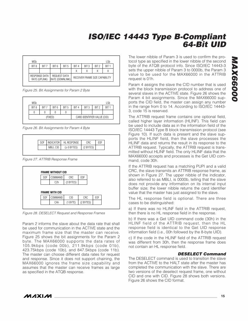
Param 2 informs the slave about the data rate that shallbe used for communication in the ACTIVE state and themaximum frame size that the master can receive.Figure 25 shows the bit assignments for the Param 2byte. The MAX66000 supports the data rates of105.9kbps (code 00b), 211.9kbps (code 01b),423.75kbps (code 10b), and 847.5kbps (code 11b).The master can choose different data rates for requestand response. Since it does not support chaining, theMAX66000 ignores the frame size capability andassumes that the master can receive frames as largeas specified in the ATQB response.
The lower nibble of Param 3 is used to confirm the pro-tocol type as specified in the lower nibble of the secondbyte of the ATQB protocol info. Since ISO/IEC 14443-3sets the upper nibble of Param 3 to 0000b, the Param 3value to be used for the MAX66000 in the ATTRIBrequest is 01h.
Param 4 assigns the slave the CID number that is usedwith the block transmission protocol to address one ofseveral slaves in the ACTIVE state. Figure 26 shows theParam 4 bit assignments. Since the MAX66000 sup-ports the CID field, the master can assign any numberin the range from 0 to 14. According to ISO/IEC 14443-3, code 15 is reserved.
The ATTRIB request frame contains one optional field,called higher layer information (HLINF). This field canbe used to include data as in the information field of theISO/IEC 14443 Type B block transmission protocol (seeFigure 10). If such data is present and the slave sup-ports the HLINF field, then the slave processes theHLINF data and returns the result in its response to theATTRIB request. Typically, the ATTRIB request is trans-mitted without HLINF field. The only HLINF data that theMAX66000 accepts and processes is the Get UID com-mand, code 30h.
If the ATTRIB request has a matching PUPI and a validCRC, the slave transmits an ATTRIB response frame, asshown in Figure 27. The upper nibble of the indicator,also referred to as MBLI, is 0000b, telling that the slavedoes not provide any information on its internal inputbuffer size; the lower nibble returns the card identifiervalue that the master has just assigned to the slave.
The HL response field is optional. There are threecases to be distinguished:
a) If there was no HLINF field in the ATTRIB request,then there is no HL response field in the response.
b) If there was a Get UID command code (30h) in theHLINF field of the ATTRIB request, then the HLresponse field is identical to the Get UID responseinformation field (i.e., 00h followed by the 8-byte UID).
c) If the code in the HLINF field of the ATTRIB requestwas different from 30h, then the response frame doesnot contain an HL response field.
DESELECT CommandThe DESELECT command is used to transition the slavefrom the ACTIVE to the HALT state after the master hascompleted the communication with the slave. There aretwo versions of the deselect request frame, one withoutCID and one with CID. Figure 28 shows both versions.Figure 26 shows the CID format.
BIT 8 BIT 7 BIT 6 BIT 5 BIT 4 BIT 3 BIT 2 BIT 1MSb LSb
X X X X
RESPONSE DATARATE (UPLINK) RECEIVER FRAME SIZE CAPABILITYREQUEST DATA
RATE (DOWNLINK)
Figure 25. Bit Assignments for Param 2 Byte
BIT 8 BIT 7 BIT 6 BIT 5 BIT 4 BIT 3 BIT 2 BIT 1MSb LSb
0
(FIXED) CARD IDENTIFIER VALUE (CID)
0 0 0
Figure 26. Bit Assignments for Param 4 Byte
SOF
FRAME WITHOUT CID
CRC EOF
(2 BYTES)
COMMAND
C2h
SOF
FRAME WITH CID
CRC EOF
(2 BYTES)
CID
(1 BYTE)
COMMAND
CAh
Figure 28. DESELECT Request and Response Frames
INDICATORSOF CRC EOF
MBLI, CID (2 BYTES)
HL RESPONSE
(≥ 0 BYTES)
Figure 27. ATTRIB Response Frame
MA
X6
60
00
ISO/IEC 14443 Type B-Compliant64-Bit UID
16 ______________________________________________________________________________________
Logically, the DESELECT command is a special case ofthe S-block of the block transmission protocol, asdefined in part 4 of the ISO/IEC 14443 standard. TheMAX66000 responds to a DESELECT command if theCID in the request and the CID in the device match. Ifthe DESELECT request does not include a CID, theMAX66000 only responds to the request if its CID is0000b.
The response frame to the DESELECT command isidentical to the request frame. The slave returns thesame data that it had received, confirming that theslave addressed in the request has been transitioned tothe HALT sate.
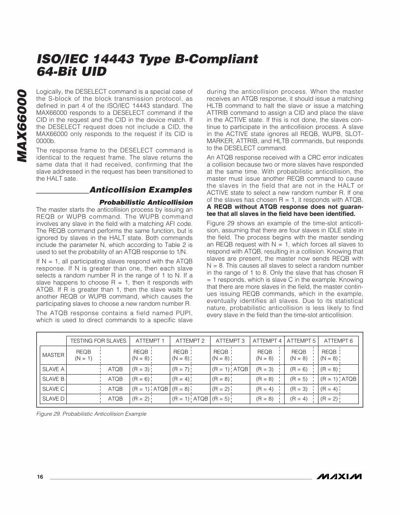
Anticollision ExamplesProbabilistic Anticollision
The master starts the anticollision process by issuing anREQB or WUPB command. The WUPB commandinvolves any slave in the field with a matching AFI code.The REQB command performs the same function, but isignored by slaves in the HALT state. Both commandsinclude the parameter N, which according to Table 2 isused to set the probability of an ATQB response to 1/N.
If N = 1, all participating slaves respond with the ATQBresponse. If N is greater than one, then each slaveselects a random number R in the range of 1 to N. If aslave happens to choose R = 1, then it responds withATQB. If R is greater than 1, then the slave waits foranother REQB or WUPB command, which causes theparticipating slaves to choose a new random number R.
The ATQB response contains a field named PUPI,which is used to direct commands to a specific slave
during the anticollision process. When the masterreceives an ATQB response, it should issue a matchingHLTB command to halt the slave or issue a matchingATTRIB command to assign a CID and place the slavein the ACTIVE state. If this is not done, the slaves con-tinue to participate in the anticollision process. A slavein the ACTIVE state ignores all REQB, WUPB, SLOT-MARKER, ATTRIB, and HLTB commands, but respondsto the DESELECT command.
An ATQB response received with a CRC error indicatesa collision because two or more slaves have respondedat the same time. With probabilistic anticollision, themaster must issue another REQB command to causethe slaves in the field that are not in the HALT orACTIVE state to select a new random number R. If oneof the slaves has chosen R = 1, it responds with ATQB.A REQB without ATQB response does not guaran-tee that all slaves in the field have been identified.
Figure 29 shows an example of the time-slot anticolli-sion, assuming that there are four slaves in IDLE state inthe field. The process begins with the master sendingan REQB request with N = 1, which forces all slaves torespond with ATQB, resulting in a collision. Knowing thatslaves are present, the master now sends REQB withN = 8. This causes all slaves to select a random numberin the range of 1 to 8. Only the slave that has chosen R= 1 responds, which is slave C in the example. Knowingthat there are more slaves in the field, the master contin-ues issuing REQB commands, which in the example,eventually identifies all slaves. Due to its statisticalnature, probabilistic anticollision is less likely to findevery slave in the field than the time-slot anticollision.
TESTING FOR SLAVES ATTEMPT 1 ATTEMPT 2 ATTEMPT 3 ATTEMPT 4 ATTEMPT 5 ATTEMPT 6
MASTER REQB (N = 1)
REQB (N = 8)
REQB (N = 8)
REQB (N = 8)
REQB (N = 8)
REQB (N = 8)
REQB (N = 8)
SLAVE A ATQB (R = 3) (R = 7) (R = 1) ATQB (R = 3) (R = 6) (R = 8)
SLAVE B ATQB (R = 6) (R = 4) (R = 8) (R = 8) (R = 5) (R = 1) ATQB
SLAVE C ATQB (R = 1) ATQB (R = 8) (R = 2) (R = 4) (R = 3) (R = 4)
SLAVE D ATQB (R = 2) (R = 1) ATQB (R = 5) (R = 8) (R = 4) (R = 2)
Figure 29. Probabilistic Anticollision Example
MA
X6
60
00
ISO/IEC 14443 Type B-Compliant64-Bit UID
______________________________________________________________________________________ 17
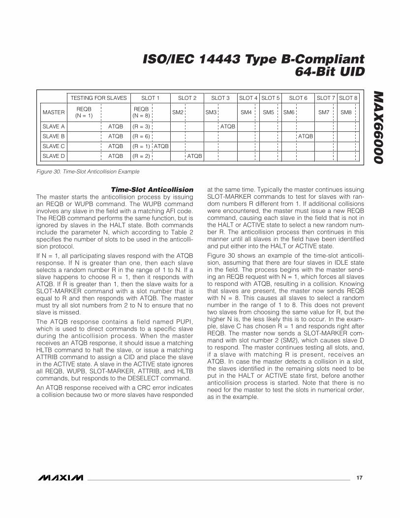
Time-Slot AnticollisionThe master starts the anticollision process by issuingan REQB or WUPB command. The WUPB commandinvolves any slave in the field with a matching AFI code.The REQB command performs the same function, but isignored by slaves in the HALT state. Both commandsinclude the parameter N, which according to Table 2specifies the number of slots to be used in the anticolli-sion protocol.
If N = 1, all participating slaves respond with the ATQBresponse. If N is greater than one, then each slaveselects a random number R in the range of 1 to N. If aslave happens to choose R = 1, then it responds withATQB. If R is greater than 1, then the slave waits for aSLOT-MARKER command with a slot number that isequal to R and then responds with ATQB. The mastermust try all slot numbers from 2 to N to ensure that noslave is missed.
The ATQB response contains a field named PUPI,which is used to direct commands to a specific slaveduring the anticollision process. When the masterreceives an ATQB response, it should issue a matchingHLTB command to halt the slave, or issue a matchingATTRIB command to assign a CID and place the slavein the ACTIVE state. A slave in the ACTIVE state ignoresall REQB, WUPB, SLOT-MARKER, ATTRIB, and HLTBcommands, but responds to the DESELECT command.
An ATQB response received with a CRC error indicatesa collision because two or more slaves have responded
at the same time. Typically the master continues issuingSLOT-MARKER commands to test for slaves with ran-dom numbers R different from 1. If additional collisionswere encountered, the master must issue a new REQBcommand, causing each slave in the field that is not inthe HALT or ACTIVE state to select a new random num-ber R. The anticollision process then continues in thismanner until all slaves in the field have been identifiedand put either into the HALT or ACTIVE state.
Figure 30 shows an example of the time-slot anticolli-sion, assuming that there are four slaves in IDLE statein the field. The process begins with the master send-ing an REQB request with N = 1, which forces all slavesto respond with ATQB, resulting in a collision. Knowingthat slaves are present, the master now sends REQBwith N = 8. This causes all slaves to select a randomnumber in the range of 1 to 8. This does not preventtwo slaves from choosing the same value for R, but thehigher N is, the less likely this is to occur. In the exam-ple, slave C has chosen R = 1 and responds right afterREQB. The master now sends a SLOT-MARKER com-mand with slot number 2 (SM2), which causes slave Dto respond. The master continues testing all slots, and,if a slave with matching R is present, receives anATQB. In case the master detects a collision in a slot,the slaves identified in the remaining slots need to beput in the HALT or ACTIVE state first, before anotheranticollision process is started. Note that there is noneed for the master to test the slots in numerical order,as in the example.
TESTING FOR SLAVES SLOT 1 SLOT 2 SLOT 3 SLOT 4 SLOT 5 SLOT 6 SLOT 7 SLOT 8
MASTER REQB(N = 1)
REQB(N = 8) SM2 SM3 SM4 SM5 SM6 SM7 SM8
SLAVE A ATQB (R = 3) ATQB
SLAVE B ATQB (R = 6) ATQB
SLAVE C ATQB (R = 1) ATQB
SLAVE D ATQB (R = 2) ATQB
Figure 30. Time-Slot Anticollision Example
MA
X6
60
00
ISO/IEC 14443 Type B-Compliant64-Bit UID
18 ______________________________________________________________________________________
Figure 31. CRC-16-CCITT Generator
1STSTAGE
MSb
LSb
2NDSTAGE
7THSTAGE
8THSTAGE
6THSTAGE
X0 X1
3RDSTAGE
4THSTAGE
5THSTAGE
X2 X3 X4
POLYNOMIAL = X16 + X12 + X5 + 1
INPUT DATA
X5 X6
11THSTAGE
X11
9THSTAGE
10THSTAGE
X9 X10
12THSTAGE
15THSTAGE
14THSTAGE
13THSTAGE
X12 X13 X14
X7
16THSTAGE
X16X15X8
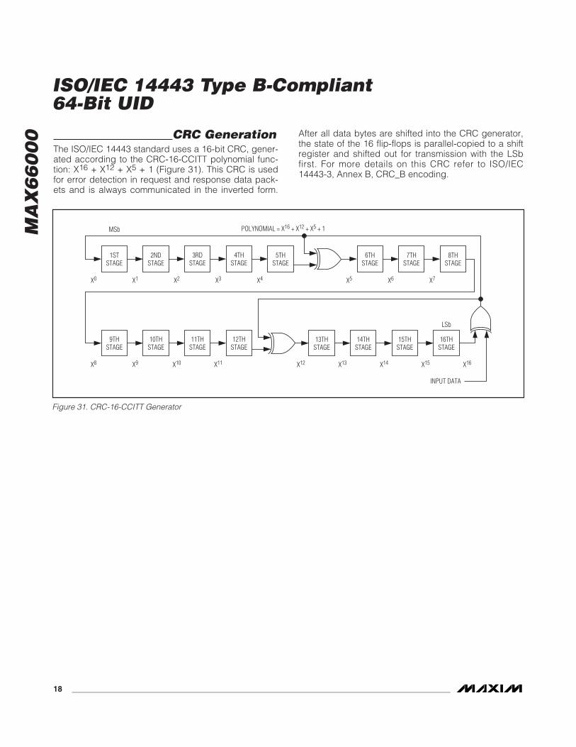
CRC GenerationThe ISO/IEC 14443 standard uses a 16-bit CRC, gener-ated according to the CRC-16-CCITT polynomial func-tion: X16 + X12 + X5 + 1 (Figure 31). This CRC is usedfor error detection in request and response data pack-ets and is always communicated in the inverted form.
After all data bytes are shifted into the CRC generator,the state of the 16 flip-flops is parallel-copied to a shiftregister and shifted out for transmission with the LSbfirst. For more details on this CRC refer to ISO/IEC14443-3, Annex B, CRC_B encoding.
MA
X6
60
00
ISO/IEC 14443 Type B-Compliant64-Bit UID
______________________________________________________________________________________ 19
SYMBOL DESCRIPTION
GSY Command “Get System Information”
GUID Command “Get UID”
SOF Start Of Frame
PCB Protocol Control Byte (see section ISO/IEC 14443 Block Transmission Protocol for details)
[CID] The tag’s assigned card identifier (see section Network Function Commands for details). The brackets [ ] indicate that the transmission of the CID depends on the Protocol Control Byte (PCB).
CRC-16 Transmission of an inverted CRC-16 (2 bytes) generated according to CRC16-CCITT.
EOF End Of Frame
IND Response indicator byte
IFLG Info Flags byte
UID The tag’s unique 8-byte identification number
DB Dummy byte
AFI Application Family Identifier byte
NBLK Number of Blocks byte (slave memory size indicator)
MBS Memory Block Size byte (slave memory block size)
ICR IC-Reference byte (slave chip revision)
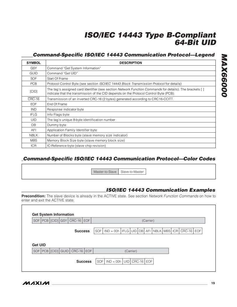
Command-Specific ISO/IEC 14443 Communication Protocol—Legend
Master-to-Slave Slave-to-Master
Command-Specific ISO/IEC 14443 Communication Protocol—Color Codes
SOF PCB GUID EOF (Carrier)[CID] CRC-16
Get UID
Success SOF EOFIND = 00h CRC-16
SOF
SOF EOFUID
UID
AFI ICRMBSIFLG NBLKDBIND = 00h
PCB GSY EOF (Carrier)[CID] CRC-16
Get System Information
Success CRC-16
ISO/IEC 14443 Communication ExamplesPrecondition: The slave device is already in the ACTIVE state. See section Network Function Commands on how toenter and exit the ACTIVE state.
MA
X6
60
00
ISO/IEC 14443 Type B-Compliant64-Bit UID
20 ______________________________________________________________________________________
MAX66000K-000AA+
TOP VIEW
SIDE VIEW
54mm
28mm 7.7mm
1.6mm
85.60mm
53.98mm
0.76mm
14.29mm
3.49mm
MA
X66
000E
-000
AA
+
TOP VIEW
SIDE VIEW
KEY FOB
ISO CARD
Mechanical Drawings
MA
X6
60
00
ISO/IEC 14443 Type B-Compliant64-Bit UID
Maxim cannot assume responsibility for use of any circuitry other than circuitry entirely embodied in a Maxim product. No circuit patent licenses areimplied. Maxim reserves the right to change the circuitry and specifications without notice at any time.
Maxim Integrated Products, 120 San Gabriel Drive, Sunnyvale, CA 94086 408-737-7600 ____________________ 21
© 2011 Maxim Integrated Products Maxim is a registered trademark of Maxim Integrated Products, Inc.
Revision HistoryREVISION NUMBER
REVISION DATE
DESCRIPTIONPAGES
CHANGED
0 1/11 Initial release —


![Rf Mgr Mnmn 14443 Refguide[1]](https://img.pdfslide.net/doc/110x75/577cd51a1a28ab9e7899e3c2/rf-mgr-mnmn-14443-refguide1.jpg)