Embed Size (px)
Citation preview
i
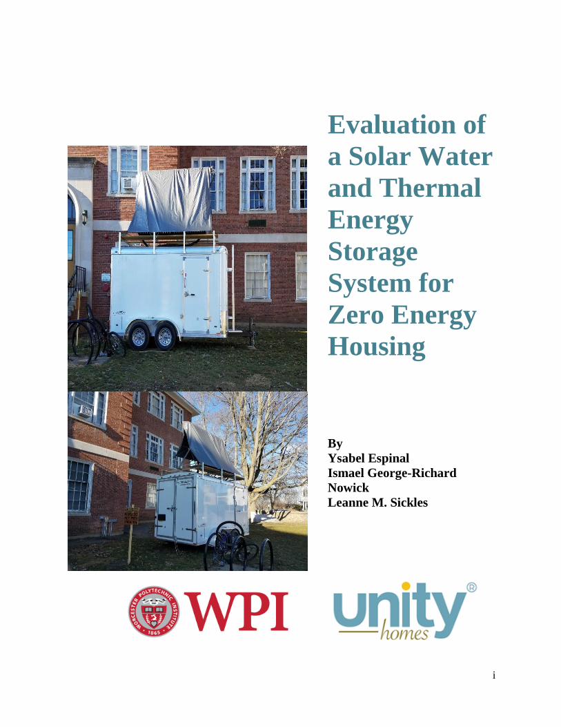
Evaluation of
a Solar Water
and Thermal
Energy
Storage
System for
Zero Energy
Housing
By
Ysabel Espinal
Ismael George-Richard
Nowick
Leanne M. Sickles
ii
Evaluation of a Solar Water and Thermal
Energy Storage System for
Zero Energy Housing
This report represents the work of WORCESTER POLYTECHNIC INSTITUTE
undergraduate students submitted to the faculty as evidence of completion of a degree
requirement. WPI routinely publishes these reports on its website without editorial or peer
review. For more information about the projects program at WPI, please see:
http://www.wpi.edu/academics/undergradstudies/project-learning.html
Submitted by:
Ysabel Espinal, Ismael George-Richard Nowick, and Leanne M. Sickles
Project Advisors:
Professor Steven Van Dessel, Director of Architectural Engineering
Professor Ali Fallahi, Assistant Teaching Professor
iii
Abstract
Residences account for 21% of the total energy demand in the United States, one-third of
which is due to heating, ventilation, and air conditioning (HVAC) systems. As such, there is
great potential to reduce the consumption of HVAC systems thus decreasing the home’s overall
energy demand. The company Unity Homes is working to address this concern by selling energy
efficient homes to the general public. In collaboration with Unity Homes, we sought to re-
innovate the design of a solar water and thermal energy storage (TES) system to be used within
one of their homes. We recommend further investigation into the feasibility of the integration of
our system as well as the potential for use as a cooling and domestic hot water system.
iv
Acknowledgements
We would like to thank our advisors, Professor Van Dessel and Professor Ali Fallahi
for guiding us through our research and system implementation. Both their ideas, support, and
interests encouraged us to move forward throughout the academic year.
We would also like to express our gratitude to our project advisor and sponsor, Ed
Curtis, for providing the funds and necessary information to complete the construction of our
system.
Additionally, we would like to thank Russell Lang, Lab Manager of the Civil &
Environmental Engineering Department at WPI, for aiding the group throughout the construction
of the system and offering his support and guidance. This project would have not been done
without you.
Finally, we would like to extend our sincere thanks to following individuals, departments,
institutions, and organizations for supporting us throughout the completion of this major
qualifying project:
Andrew Dey, Operations Director of Unity Homes, for giving us the opportunity to visit
and evaluate their house platforms.
Professor Kenneth M. Elovitz, Adjunct Teaching Professor at Worcester Polytechnic
Institute, for helping us with the mechanical components of our project.
Ted McCarty and his crew, Lead Electrician at WPI, for offering their skills and
knowledge in wiring the trailer, and
Professors James O’Rourke and Stephen Bitar of the Electrical and Computer
Engineering Department at WPI, for offering their time and knowledge on the control
schematics for our system.
v
Table of Contents Abstract .......................................................................................................................................... iii
Acknowledgements ........................................................................................................................ iv
Authorship.................................................................................................................................... viii
List of Figures ................................................................................................................................. x
List of Tables ............................................................................................................................... xiii
Executive Summary ..................................................................................................................... xiv
1.0 Introduction ............................................................................................................................... 1
2.0 Background ............................................................................................................................... 3
2.1 History of Heating New England Homes .............................................................................. 3
2.2 Net Zero Energy Design for Homes ...................................................................................... 3
2.3 Passive Methods for Zero Energy Design ............................................................................. 6
2.3.1 Optimizing Building Envelopes ..................................................................................... 7
2.3.2 Orientation and Effective Site Planning ......................................................................... 8
2.3.3 Passive Designs .............................................................................................................. 9
2.3.3a Thermal Energy Storage Methods and Systems ....................................................... 9
2.3.3b Trombe Wall ........................................................................................................... 11
2.3.3c Water Wall .............................................................................................................. 12
2.3.3d Basic Passive Solar with Thermal Mass ................................................................. 13
2.4 Active Methods for Zero Energy Design Systems within Homes ...................................... 14
2.4.1 Solar Water Heater Systems ......................................................................................... 14
2.4.1a Solar Collectors ....................................................................................................... 14
2.4.1b Variance in Evacuated Tube Collectors .................................................................. 18
2.4.1c Open-Loop and Closed-Loop Active Systems ........................................................ 19
2.4.2 Geothermal Heat Transferring Systems ....................................................................... 21
2.4.3 Electrical Systems......................................................................................................... 22
2.4.3a Traditional Electrical Systems ................................................................................ 22
2.4.3b Photovoltaic Cells ................................................................................................... 23
2.5 Unity Homes ....................................................................................................................... 24
2.5.1 Design ........................................................................................................................... 25
2.5.2 Construction Process .................................................................................................... 29
vi
2.5.3 Materials ....................................................................................................................... 30
2.5.4 Mechanical Systems ..................................................................................................... 31
2.5.5 Passive House Standard ................................................................................................ 32
3.0 Problem Statement and Objectives ......................................................................................... 34
4.0 Experimental Set-Up and System Functionality ..................................................................... 35
4.1 Experimental Set-Up ........................................................................................................... 35
4.2 System Functionality ........................................................................................................... 47
5.0 Methodology ........................................................................................................................... 49
5.1 Objective 1: Improve the Design of a Unity Home Using Passive Methods ...................... 49
5.2 Objective 2: Design, Build, and Test an Innovative Heating System ................................. 50
5.2.1 Site Selection ................................................................................................................ 50
5.2.2 Peak Heating Load Profile ............................................................................................ 51
5.2.3 Materials, Equipment and Sizing.................................................................................. 55
5.2.3a Solar Collector ........................................................................................................ 55
5.2.3b Heat Pump ............................................................................................................... 56
5.2.3c Storage Drums ......................................................................................................... 56
5.2.3d Circulating Pumps ................................................................................................... 56
5.2.3e Expansion Tanks ..................................................................................................... 58
5.2.3f Piping ....................................................................................................................... 58
5.2.3g Valves ..................................................................................................................... 59
5.2.3h Sensors .................................................................................................................... 59
5.2.3i Insulation ................................................................................................................. 60
5.2.3j Fluids ....................................................................................................................... 61
5.2.5 Creating a Mathematical Model ................................................................................... 62
5.2.6 System Design .............................................................................................................. 67
5.2.7 System Construction ..................................................................................................... 67
5.2.8 Electrical Design and Controls ..................................................................................... 68
5.3 Objective 3: Feasibility of Unity Home Integration............................................................ 68
5.4 Objective 4: Develop a Set of Strategies and Recommendations ....................................... 69
6.0 Results ..................................................................................................................................... 70
6.1 Objective 1: Improve the Design of a Unity Home Using Passive Methods ...................... 70
vii
Rotation ..................................................................................................................................... 72
6.2 Objective 2: Design, Build, and Test an Innovative Heating System ................................. 73
6.2.1 Peak Heating Load Profile ............................................................................................ 73
6.2.2 Equipment Sizing ......................................................................................................... 76
6.2.3 Creating a Mathematical Model ................................................................................... 77
6.2.4 System Design and Construction .................................................................................. 78
6.2.5 Electrical Design and Controls ..................................................................................... 79
6.3 Objective 3: Feasibility of Unity Home Integration............................................................ 81
6.4 Objective 4: Develop a Set of Strategies and Recommendations ....................................... 82
Conclusions ................................................................................................................................... 85
References ..................................................................................................................................... 86
Appendix A: Nomenclature .......................................................................................................... 89
Appendix B: Heat Balance Equations for Design Space Heating ................................................ 93
Appendix C: Pump Control Flow Chart ....................................................................................... 94

viii
Authorship
Primary
Author
Secondary
Author Editor
Introduction YE -- LS
Background
History of Heating New England Homes LS -- LS
Net Zero Energy Design for Homes LS -- LS
Passive Methods for Zero Energy Design IN LS LS
Optimizing Building Envelopes IN LS LS
Orientation and Effective Site Planning IN LS LS
Passive Designs IN LS LS
Active Methods for Zero Energy Design
Systems within Homes YE -- LS
Solar Water Heater Systems YE -- LS
Geothermal Heat Transferring Systems YE -- LS
Electrical Systems YE -- LS
Unity Homes LS -- LS
Design LS -- LS
Construction Process LS -- LS
Materials LS -- LS
Mechanical Systems LS -- LS
Passive House Standard LS -- LS
Problem Statement and Objectives LS -- LS
Experimental Set Up and System Functionality
Experimental Set Up YE LS LS
System Functionality YE LS LS
Methodology
Objective 1 LS IN LS
Objective 2 LS -- LS
Site Selection YE LS LS
Establishing a Peak Heating Load Profile YE -- LS
Materials, Equipment and Sizing YE LS LS
Creating a Mathematical Model YE LS LS
System Design LS -- LS
System Construction LS -- LS
Electrical Design and Controls YE -- LS
Objective 3 IN LS LS
Objective 4 LS -- LS
Results
ix
Objective 1 IN -- LS
Objective 2 YE LS LS
Establishing a Peak Heating Load Profile YE -- LS
Equipment Sizing YE -- LS
Creating a Mathematical Model LS -- LS
System Design and Construction LS -- LS
Electrical Design and Controls YE -- LS
Objective 3 LS -- LS
Objective 4 LS -- LS
Conclusion LS -- LS
x
List of Figures Figure 1: Thermal Energy Storage Methods: (a) Sensible, (b) Latent, and (c) Thermochemical Recations ..... 10
Figure 2: Trombe Wall at NREL’s Visitor Center ................................................................................................. 11
Figure 3: Northern Hemisphere Trombe Wall Schematic ..................................................................................... 12
Figure 4: Thermal Mass in the Winter (Top) and Thermal Mass in the Summer (Bottom) .............................. 14
Figure 5: Glazed Flat Plate Solar Collector ............................................................................................................ 15
Figure 6: Unglazed Flat Plate Solar Collector ........................................................................................................ 16
Figure 7: Evacuated Tube Array and Cross-Section .............................................................................................. 17
Figure 8: Direct Flow Evacuated Tube Collector ................................................................................................... 18
Figure 9: Heat Pipe Evacuated Tube Schematic ..................................................................................................... 19
Figure 10: Indirect Solar Water Heater System ..................................................................................................... 21
Figure 11: Geothermal System ................................................................................................................................. 22
Figure 12: Typical Home Electrical Distribution System ...................................................................................... 23
Figure 13: Photovoltaic Cell Configuration ............................................................................................................ 24
Figure 14: Tradd Exterior ........................................................................................................................................ 26
Figure 15: Tradd First (Left) and Second (Right) Level Floor Plans ................................................................... 26
Figure 16: Xyla Exterior ........................................................................................................................................... 27
Figure 17: Xyla Floor Plan........................................................................................................................................ 27
Figure 18: Värm Exterior ......................................................................................................................................... 28
Figure 19: Värm First (Left) and Second (Right) Level Floor Plans .................................................................... 28
Figure 20: Zūm Exterior ........................................................................................................................................... 29
Figure 21: Zūm Floor Plan ....................................................................................................................................... 29
Figure 22: Wall Panels Being Assembled in Unity Homes’ Factory ..................................................................... 30
Figure 23: Wall Section ............................................................................................................................................. 31
Figure 24: Typical Energy Usage in the Residential Sector ................................................................................... 32
Figure 25: Solar Water Heating System Design ...................................................................................................... 35
Figure 26: Assembled Solar Collector Frame ......................................................................................................... 36
Figure 27: Solar Collector Frame Mounted to the Trailer .................................................................................... 36
xi
Figure 28: Method for Attaching Steel Tubing ....................................................................................................... 37
Figure 29: Running the Steel Tubing into the Trailer ............................................................................................ 38
Figure 30: Connections Made to Drum Lid ............................................................................................................ 39
Figure 31: Insulating the Side of the Trailer ........................................................................................................... 39
Figure 32: Line Piping Connecting Drums .............................................................................................................. 41
Figure 33: Heat Pump, March Pump and Mixing Loop Set-Up ............................................................................ 43
Figure 34: Applying Heat Transfer Paste and Soapy Water ................................................................................. 44
Figure 35: Electrical Set Up (Left) and Drum Temperature Sensors (Right) ...................................................... 45
Figure 36: Attaching the Hose to the Wilo Star and Small Pumps ....................................................................... 45
Figure 37: Glycol Bucket (Left) and Bubbles in the Clear Hose (Right) .............................................................. 46
Figure 38: Solar Water Heating System Design: Charging ................................................................................... 47
Figure 39: Solar Water Heating System Design: Heating ...................................................................................... 48
Figure 40: Xyla Model ............................................................................................................................................... 49
Figure 41: Project Site Location ............................................................................................................................... 51
Figure 42: Heat Balance Flow Chart ....................................................................................................................... 52
Figure 43: Trailer Wall Surfaces .............................................................................................................................. 53
Figure 44: DesignBuilder Trailer Design ................................................................................................................. 55
Figure 46: Preliminary Trailer Designs ................................................................................................................... 57
Figure 47: Freezing and Boiling Points of Propylene Glycol Solution .................................................................. 61
Figure 48: Fluid Temperature within Storage Drums for a 24 Day Cycle (attempt 1) ....................................... 64
Figure 49: Fluid Temperature within Storage Drums for a 24 Day Cycle (attempt 2) ....................................... 65
Figure 50: Home Base Orientation ........................................................................................................................... 72
Figure 51: Winter Design Day, Hourly Outdoor Temperatures ........................................................................... 73
Figure 52: Winter Design Day, Solar Irradiation Values ....................................................................................... 74
Figure 53: Solar Irradiation Values for December (Left) and February (Right) ................................................ 74
Figure 54: Winter Design Day, Trailer Heat Gains and Losses ............................................................................ 75
Figure 55: DesignBuilder, Trailer Heat Gains and Losses ..................................................................................... 75
Figure 56: Daily Storage Temperatures for As Built System ................................................................................ 77

xii
Figure 57: Hourly Storage Temperatures for As Built System ............................................................................. 78
Figure 58: Proposed Control Schematic .................................................................................................................. 81
Figure 59: Daily Storage Temperatures for Xyla Platform ................................................................................... 82
xiii
List of Tables Table 1: Comparison of Window Types .................................................................................................................. 70
Table 2: Comparison of Wall Insulation ................................................................................................................. 71
Table 3: Comparison of Home Orientation ............................................................................................................. 72
Table 4: Material and Equipment Sizing ................................................................................................................ 76
Table 5: Summary of Electrical Components ......................................................................................................... 79
Table 6: Pump Schedule ............................................................................................................................................ 80
xiv
Executive Summary
Introduction
In the United States, buildings account for 38% of all carbon dioxide emissions, they
consume 13.6% of all potable water (15 trillion gal./year), and use 73% of the total electricity
consumption ("This is LEED: Better Buildings are out Legacy," n.d.). In 2007, an annual energy
review performed by the U.S. Energy Information Administration (EIA) revealed that residences
account for 21% of the total energy demand in the United States (Meyers, 2010). Furthermore, a
2009 Building Energy Database concluded that heating, ventilation, and air conditioning
(HVAC) systems account for one-third of a building’s energy consumption (Noonan et al.,
2013). The company Unity Homes is working to address this issue by selling energy efficient
homes to the general public. In collaboration with Unity Homes, we sought to re-innovate the
design of a solar water and thermal energy storage (TES) system to be used within a New
England Home.
Background
Our project focuses on designing a solar water heating and thermal energy storage (TES)
system to minimize energy usage within single-family homes. To better understand the need for
such a system and determine how it can be optimized for a single-family home we conducted
research that focused on the optimization of a home through passive methods using the
successful design of the homes built by Unity Homes as an example. We first discuss the
different methods for heating and cooling homes that have been used and which lead to the most
recent stride of building optimization and energy efficiency: net zero energy. Achieving a net
zero energy design requires the building to be optimized both passively and actively, we examine
methods used to meet these standards. Lastly, we discuss the design and building process of the
net zero energy homes produced by Unity Homes as their homes are the platform for our solar
water heating system.
Process
In collaboration with Unity Homes, we sought to improve their home design by
investigating both passive and active changes to their design. In order to complete this goal we
completed the following tasks:
1. Improve the design of a Unity Home using passive methods through simulation using
energy modeling software
xv
2. Design, build, and test an innovative heating system to heat a small space during the
winter season
3. Determine the feasibility for our innovative heating system to be used within a Unity
home
4. Develop a set of strategies and recommendations for ways to further our research and
improve Unity Home’s house design both passively and actively
Recommendations
Passive Changes for Unity Homes
We recommend that Unity Homes continues to use their current design and
construction methods. Based on our energy modeling we found that the current window type,
insulation, and orientation of Unity Home’s houses provides the most efficient and cost effective
solution.
Future Work on Solar Water Heating System
We recommend that a future project be developed to further extend and integrate a
controls set up for our system. The control schematic, pump schedule, and pump control flow
chart that we created should help guide future work as they collectively describe how our system
is intended to operate. In addition to the automatic control of the pumps and motorized valve, the
temperature sensors attached along the piping and the sides of the drums of the heating loop
should be connected to the RESOL controller, or an alternative source, in order to automatically
collect temperature at specified time intervals. A proper controls set-up to accomplish these two
tasks will allow our system to function seamlessly and without manual operation.
We recommend that a future project be developed to continue our work on creating
an operable system. Further investigation is needed to determine why the solar loop is not able
to maintain pressure. Once a conclusion is reached and the necessary steps are taken to solve the
problem, filling of the heating loop can commence. Successful filling of both loops will allow
the system to be turned on and data collection can begin.
We recommend that a future project be developed to modify our system to allow for
space cooling and domestic hot water use. The marine heat pump that we purchased has the
ability to operate in cooling mode. Modifying our system to include space cooling would
increase its usefulness as it would be able to function as a modern HVAC system currently does.
When conducting research for building our system we found that similar systems to ours had
xvi
been developed to provide hot water to homes. Thus, we believe that the integration of domestic
hot water into our system is possible and we believe that a final version of our system that
includes heating, cooling and domestic hot water is a system that Unity Homes is looking to
integrate into their homes.
Unity Homes Integration
We recommend that further investigation be made to obtain a system efficiency
value. In order to successfully integrate our system model into the Xyla platform and overall
efficiency value needs to be calculated. This calculation can only be made once results are
obtained from either a mathematical model or experimental testing. If a model will be used,
further work to develop the mathematical model that we presented in this paper is necessary to
accurately represent our system. Alternatively, a new model could be used or newly developed to
satisfy our system parameters.
We recommend that serious consideration be taken to determine the feasibly of
integrating our system into a Unity Homes house. Because our system requires a large amount
of space, thought needs to be given as to where the system will be located. Depending on the
number of solar collectors and storage drums necessary the drums may be able to be located
inside the home, possibly in the basement. Additionally, thought must be given to the appearance
of the system and whether or not a roof mounted solar collector will be favorable over a ground
mounted system.
We recommend that a cost analysis be performed to compare our systems costs with
the cost of the HVAC system already used within a Unity Home. Taking into account both
the initial cost of the system as well as the cost savings allowed by the elimination of electric or
gas consumption a cost analysis can be performed. This analysis will further illustrate the
feasibility of the integration of our system. Additionally, calculations and an associated cost
analysis can be performed for our system with the addition of using solar panels as a means to
power our system. This addition to our system would not only provide potential long term cost
savings, it would also create an HVAC system to help in achieving a net zero energy house
design.
Conclusions
The goal of our project was to improve Unity Home’s home design by investigating both
passive and active methods. We conducted research, performed energy modeling analyses, and

xvii
built a solar water heating system to formulate recommendations for Unity Homes and future
WPI students. Our research assisted us in choosing variables to consider when attempting to
passively improve Unity Home’s design. The energy modeling that we performed to accomplish
this allowed us to conclude that Unity Home’s current design and construction techniques are the
most efficient and cost effective. When considering active improvements we were able to
conclude that our system would need to include an additional solar collector in order to
effectively heat either the trailer or the Xyla house. We were also able to formulate many
recommendations to assist future WPI project teams that continue our work as they outline our
intentions for successfully completing of our work as well as additional topics to investigate
upon obtaining further results.
1
1.0 Introduction
In the United States, buildings account for 38% of all carbon dioxide emissions, they
consume 13.6% of all potable water (15 trillion gal./year), and use 73% of the total electricity
consumption ("This is LEED: Better Buildings are our Legacy," n.d.). In 2007, an annual energy
review performed by the U.S. Energy Information Administration (EIA) revealed that residences
account for 21% of the total energy demand in the United States (Meyers, 2010). Furthermore, a
2009 Building Energy Database concluded that heating, ventilation, and air conditioning
(HVAC) systems account for one-third of a building’s energy consumption (Noonan et al.,
2013). Unlike commercial buildings, residences are more likely to waste energy due to the
inefficient tendencies of homeowners. As they are in direct control of the temperature and
operation settings, homeowners are more likely to set and maintain a higher temperature during
the winter and a lower temperature during the summer throughout the day with no regard to
occupancy status. In order to decrease energy consumption, technological advances must be
made to control the energy usage within residences (Meyers, 2010).
In an effort to reduce energy consumption in homes, the idea of “Net Zero Energy
Design” has been introduced. A home is considered to be net zero if the annual energy
consumption of the building is approximately equal to the amount of renewable energy generated
on site. Homeowners have been exposed to the use of solar energy such as the use of
photovoltaics, and flat or evacuated tube collectors to both generate electricity and meet heating
and/or cooling needs. In conjunction, many scholars have initiated studies to explore the use of
solar collectors as a means to provide space heating for homes. A recent study conducted by
Engineers from the Indian Institute of Technology, explored the use of a mathematical model to
determine the design space synthesis and optimization of solar water heating systems. The design
was based on a typical layout consisting of a solar collector array and an insulated storage tank.
It was observed that there was a maximum and minimum storage volume for a given solar
fraction and collector area and a maximum and minimum collector area for a given solar fraction
and storage volume (Kulkami, 2006). Their proposed data can be adopted and modified to fit
other project components and needs.
The company Unity Homes is working to address this concern by selling energy efficient
homes to the general public. In collaboration with Unity Homes, we sought to re-innovate the
design of a solar water thermal energy storage system to be used within one of their homes. After
2
meeting with the Operations Director of Unity Homes and performing preliminary research, it
was evident that the main area of improvement for their homes is the HVAC system. To
accomplish our goals of this project we carried out the following tasks: First, we aimed to
improve the design of a Unity Home using passive methods through simulation using energy
modeling software. Second, we designed, built, and tested an innovative heating system to heat a
small space during the winter season. Third, we determined the feasibility for our innovative
heating system to be used in a Unity home. Lastly, we developed strategies and
recommendations for ways to further our research and improve Unity Home’s house design both
passively and actively. By accomplishing these tasks, we were able to provide Unity Homes with
potential strategies to improve the HVAC system in their designs, and set a research platform for
future Worcester Polytechnic Institute students.
3
2.0 Background
Our project focuses on designing a solar water heating and thermal energy storage (TES)
system to minimize energy usage within single-family homes. To better understand the need for
such a system and determine how it can be optimized for a single-family home we conducted
research that focused on the optimization of a home through passive methods using the
successful design of the homes built by Unity Homes as an example. We first discuss the
different methods for heating and cooling homes that have been used and which lead to the most
recent stride of building optimization and energy efficiency: net zero energy. Achieving a net
zero energy design requires the building to be optimized both passively and actively, we examine
methods used to meet these standards. Lastly, we discuss the design and building process of the
net zero energy homes produced by Unity Homes as their homes are the platform for our solar
water heating system.
2.1 History of Heating New England Homes
As home heating stems from the need for thermal comfort, the first heating ventilation
and air conditioning (HVAC) system was introduced in the early 1900’s. It was not until later in
the century that there was a push towards energy efficiency, where the design and production of
HVAC systems began to focus on reducing energy consumption. In addition to improving the
traditional HVAC systems, newer systems that incorporate renewable resources have also been
introduced to the market. Among the most common newer HVAC system is solar heating as it is
a cost effective and pollution reducing system. As this system, and even newer systems are being
developed, new ideas, such as net zero energy, are being explored to increase efficiency and
reduce energy consumption.
2.2 Net Zero Energy Design for Homes
A building is considered to be net zero if it can generate as much energy through the use
of renewable resources as the building consumes. The concept of a net zero energy building was
most recently introduced in the Energy Independence and Security Act of 2007 where an
initiative was set forth to “...develop and disseminate technologies, practices, and policies for the
development and establishment of zero net energy commercial buildings…” (Congress, 2007).
As this initiative aims to achieve net zero energy in 50% of all commercial buildings by 2050,
there is no mention of residential buildings. Because residential buildings also play a major role
4
in annual energy consumption, the National Institute of Standards and Technology (NIST)
hosted a workshop to educate the residential building stakeholder community on achieving net
zero energy (NZE) in new and existing homes.
The workshop focused on gauging participants perspectives on the following questions:
“What are the key characteristics of future NZE homes and the residential
building community?
What are the challenges and barriers that impede the design, construction, and
purchasing of NZE homes?
What are the potential concepts that could be included in a future guidance
document for the residential building community to aid in the design and
construction of NZE homes?” (McNabb, 2013).
Each question was addressed within each of the three sections of the workshop where
each section’s collaboration resulted in a comprehensive list ranging from low to high priority
items for the design and operation of a net zero energy home. Additionally, a list of challenges
and corresponding “future guidance document” to overcome each of the challenges is described.
As a result, the workshop developed fundamental concepts that are being further developed
today as companies strive to make net zero homes a reality.
The three sections of the workshop focused on key design aspects of net zero energy
homes, key technology and equipment aspects of future net zero energy homes, and the human
element of net zero energy homes. From the sections a compiled list can be formulated to
identify high, medium and low priority items that need to be incorporated into a net zero home,
some of which are listed below:
“High:
modest footprint with minimal carbon footprint
integrated heating, cooling, ventilation and dehumidification system that is
properly sized to optimize the building performance
use of high efficiency, affordable HVAC systems
quality construction that incorporates techniques to achieve a tight, well insulated
envelope
simple systems that are easy to use and maintain
real time energy metering
5
maximize the benefits of daylighting
the use of automation and advanced controls to minimize electricity use for plug
loads
designed so that the owner can easily operate the home energy efficiently
Medium:
use of triple pane windows
use of properly sized, on-site renewable energy to generate power and heat
Low:
energy load served by a variety of methods
ventilation that is both natural and mechanical
water used efficiently and conserved
provide feedback to occupants on energy management performance through
monitoring and display systems” (McNabb, 2013).
As the participants created the lists they also noted some foreseen challenges with this list
of design and owner operation elements such as being able to “evaluate and compare energy
performance and the selection of effective technology, building materials, methods of
construction, and siting options” (McNabb, 2013). Because homeowners may not be educated as
to how changing behavior and energy use can improve energy performance or on how
purchasing a home based on maintenance costs rather than initial purchase cost can save them
money while reducing their carbon footprint, net zero energy homes may not be widely
purchased or built. Thus a “guidance element” was identified to solve this problem; the
participants suggested that a home scoring system be developed to compare the performance of
net zero homes to other homes for sale. With regards to the selection of effective technology,
building materials, methods of construction, and siting options it has been observed that the
mechanical systems in buildings, especially low load homes, are often sized incorrectly and it
was determined that the best way to address this is to wait for new technologies to be developed
that are high efficiency and affordable (McNabb, 2013).
Although a standard for net zero energy residential buildings is still yet to be officially
established, the International Living Future Institute offers a Net Zero Energy Building
Certification. This certification is one of three certifications under the Institute’s Living Building
Challenge which “is an attempt to dramatically raise the bar from a paradigm of doing less harm
6
to one in which we view our role as a steward and co-creator of a true Living Future”
(International Living Future Institute, 2017). The Challenge defines twenty imperatives that must
be achieved to meet the Challenge, four of which must be met to obtain the Net Zero Energy
Building Certification: Limits to Growth, Net Positive Energy, Beauty + Spirit and Inspiration +
Education. The Limits to Growth imperative limits a project to only being built on greyfields or
brownfields and requires that no petrochemical fertilizers or pesticides be used for the operation
and maintenance of on-site landscaping. The Net Positive Energy imperative can only be met if
one hundred percent of the project’s energy needs is supplied by on-site renewable energy on a
net annual basis without the use of on-site combustion. The Beauty + Spirit imperative relates to
the project’s integration of public art and design features intended for human delight. Finally, the
Inspiration + Education imperative requires that educational materials about the operation and
performance of the project be provided to the public in addition to hosting an annual “open day”
for the public in order to motivate others to make meaningful changes in their lives (International
Living Future Institute, 2017).
Since the initial concept of a net zero energy home was established, new strategies and
technologies have been developed and integrated into residential buildings that address many of
the items on the list created by NIST in 2011. These strategies and technologies can be easily
categorized as being either a passive or active system where different combinations of these
systems have been used to advance the design and construction of homes that make net zero
energy homes a seemingly achievable goal for the future.
2.3 Passive Methods for Zero Energy Design
In order to produce a zero energy design both passive and active methods can be
considered. Because a net zero design is achieved when the amount of energy consumed is equal
to the amount of energy produced it is most commonly thought that active systems, such as
photovoltaic cells, are the only way to attain a net zero energy design. Although these active
systems play a major role in net zero energy design, passive systems, such as the building’s
envelope and orientation, contribute greatly to the performance of a home and thus increases the
efficiency of the active systems.
7
2.3.1 Optimizing Building Envelopes
The building envelope is a large contributing factor to achieve a zero energy design as it
accounts for a large portion of the building’s heat loss in the winter and heat gain in the summer.
A building’s envelope consists of all of the walls, windows and doors, the roof and the ground
floor. For the walls, roof and floor, the heat gain and heat loss is mainly controlled by the
insulation.
Insulation works by slowing the conductive heat flow, where different insulation
materials provide a greater resistance to conductive heat flow. This resistance is measured based
on the material’s thermal resistance, its thickness and its density and is expressed as what is
known as a material's R-value. Depending on where the building is located different R-values are
recommended; larger R-value insulation has a greater insulating effectiveness and is thus
recommended in colder climates whereas in warmer climates lower R-value insulation is
recommended. It is also important to understand that the material R-value will not be the actual
R-value of the wall, roof or floor due to what is known as thermal bridging. This occurs because
heat is able to flow through studs and joists as they provide a break in the insulation and allow
for a conductive flow through the envelope. Different types of insulation have different R-values
and are more effective at reducing conductive flow. The most commonly used insulation is a
fiberglass batt insulation due to its lower cost and ability to fit into any space. Although these
benefits are appealing, in order to achieve a large R-value the thickness of the insulation must
also be large as typical batts have R-values that range from R-2.9 to R-4.3 per inch. Another type
of insulation that is commonly used is foam board insulation which has R-values that range from
R-4 to R-6.5 per inch of thickness. In addition to having a larger R-value per thickness than most
insulations, foam boards are able to reduce heat conduction through structural elements. Another
type of insulation that is becoming increasingly more common is sprayed-foam insulation.
Although this type of insulation costs more than other types of commonly used insulations,
sprayed-foam insulation has R-values that range from R-3.7 to R-6.2 per inch and practically
eliminates air leakage as it expands to completely fill any space. Because of this, sprayed-foam
insulation has been known to reduce other costs associated with weatherizing a home which
makes up for the larger initial cost of the product (Types of Insulation, n.d.).
Another element of the building envelope that contributes to the building’s heat loss and
heat gain are the windows. Similar to how studs and joists break up the continuous flow of
8
insulation in the walls, the windows also act as a break in the structure where the envelope is
susceptible to air leakage. Additionally, windows have their own efficiency factor known as the
U-value which is determined by both the material of the window frame and the glazing type
where the lower the U-value, the more energy efficient the window is. Window frames can be
made from metal, fiberglass, vinyl or wood materials which each have their own advantages and
disadvantages. In terms of thermal resistance, the most effective frames are those made of
fiberglass or vinyl as both types have air cavities that can be filled with insulation to increase
their thermal performance. The window glazing contributes greatly to the overall window
efficiency; they are many different types of glazing including insulated and low-emissivity. An
insulated window glazing has two or more panes of glass that are spaced apart leaving an
insulating air space which lowers the U-value of the window. Alternatively, a low-emissivity, or
low-e, coating on a window glazing controls heat transfer which reduces energy loss by 30 to 50
percent (Window Types, n.d.).
As the performance of a building is largely controlled by the building’s envelope,
ensuring that the conductive heat flow and the air leakage through all of the enclosure elements
is minimized is of great importance. In order to determine the effectiveness of these elements,
different tests can be performed such as a blower door test or thermal imaging. These tests
identify areas within the building where air leakage is occurring and report a value measured in
air changes per hour (ACH), where .6 ACH would qualify a building as efficient.
2.3.2 Orientation and Effective Site Planning
In addition to optimizing the building’s envelope, taking the building’s orientation into
account is important to achieve an effective passive design. When considering the orientation of
the building both the sun’s position and the climate zone play a major role. For the northern
hemisphere, south facing windows allow the most sunlight in year-round, north facing windows
admit even lighting with almost no summer heat gain, and east and west facing windows provide
daylight in the morning and evening respectively but admit a lot of heat in the summer. With
these facts in mind, careful analysis should be conducted for a particular site to obtain the
optimum orientation, where the ideal orientation would be the one to allow sunlight to penetrate
the building when it is needed and passively heat the whole house, as well as provide daylighting
to the majority of the interior spaces (Daylighting, n.d.).
9
2.3.3 Passive Designs
Using the concepts that have been developed and understood about a building’s envelope
and orientation, different techniques and designs have been developed to optimize a building.
These designs, discussed below, can be utilized for many applications within a building, but
ultimately work to optimize a building passively.
2.3.3a Thermal Energy Storage Methods and Systems
Adequate thermal energy storage (TES) methods and systems in buildings have growing
potential in energy conservation. TES can overcome the lack of thermal energy supplied through
an HVAC system and produce the energy that is demanded by the space. By applying TES in the
form of active and passive systems, wasted heat can be used, peak loads can be shifted, and an
overall more rational use of energy can be achieved. Buildings that incorporate TES have the
potential to be more reliable and efficient, less costly to operate, and more environmentally
friendly as it produces less CO2 emissions.
TES systems and methods have been classified as either passive or active systems.
Passive systems work to optimize the use of “…naturally available heat energy sources in order
to maintain the comfortable conditions in buildings and minimize the use of mechanically
assisted heating or cooling systems” (de Gracia L.F. Cabeza, 2015). Some passive systems and
methods include: Thermal mass, orientation/solar heating, shading, ventilated facades, phase
change materials, coated glazing, and free cooling (night ventilation) techniques. On the
contrary, active systems provide a large factor of control over the indoor conditions as they are
mechanically assisted. Active systems shift the “thermal load from on-peak to off-peak
conditions in several applications, such as domestic hot water, or heating, ventilation, and air-
conditioning (HVAC) systems” (de Gracia L.F. Cabeza, 2015).
There are three methods of thermal storage: Sensible, latent, and thermochemical energy
storage (see Figure 1).

10
Figure 1: Thermal Energy Storage Methods: (a) Sensible, (b) Latent, and (c) Thermochemical Recations
(de Gracia L.F. Cabeza, 2015)
Sensible heat storage is the simplest method to store thermal energy; it is facilitated by applying
a temperature gradient to a media (either liquid or solid) in order to absorb or release heat. Water
is the most commonly used sensible thermal storage material, although ceramic materials
(concrete, cement, etc.), some natural stones like marble, granite, clay, sandstone, and polymers
such as PUR, PS, and PVC are also used. Sensible heat storage is cost effective and avoids risks
from toxic materials. Often, sensible storage materials are part of the buildings structure and
therefore do not require extra space. However, sensible heat storage often requires a large
volume of material depending on the amount of desired heat energy to be stored (de Gracia L.F.
Cabeza, 2015).
On the other hand, latent storage has a higher storage density and therefore requires less
volume of material as represented in Figure 1 (b). Latent heat storage is captured through phase
change materials (PCM) which make use of the latent heat between phase changes. The process
of changing phases (solid to liquid, and reverse) in a substance either stores or releases a large
amount of energy as heat. Some materials that work well as PCM materials include paraffin,
fatty acids, and salt hydrates. Each material has specific phase change properties, such as
temperature and conductivity so each PCM is only advantageous in its own designed application
based on its physical properties (de Gracia L.F. Cabeza, 2015).
The last kind of material used in TES systems is thermochemical (Figure 1 (c)). This
process, though potentially very efficient, is under development and currently has no present
applications in the building sector. These materials store and release heat via reversible
endothermic and exothermic reactions. As seen in the schematic, a thermochemical object is
11
charged and then splits into objects B and C. These separate pieces can be stored until the energy
is desired to be released/discharged (de Gracia L.F. Cabeza, 2015).
2.3.3b Trombe Wall
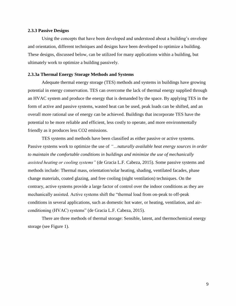
Named after Felix Trombe, who, in the late 1950’s, had engineered a simple yet effective
passive design that is still used today, a trombe wall is built on the equator-facing side of a house
where it can maximize solar gains (a northern hemisphere house would have a trombe wall
facing south; southern hemisphere, facing north).
Figure 2: Trombe Wall at NREL’s Visitor Center
(NREL, n.d.)
Trombe Walls incorporate a window, an air space and then a thick layer of thermal mass
right behind the window which helps trap solar gains during the day so that more heat will be
absorbed. The air temperature in the air gap will rise to become very high during the day
therefore forcing the heat to flow deeper into the wall since the temperature gradient across the
thermal mass layer from the air gap to the living space conditions will be very large.
12
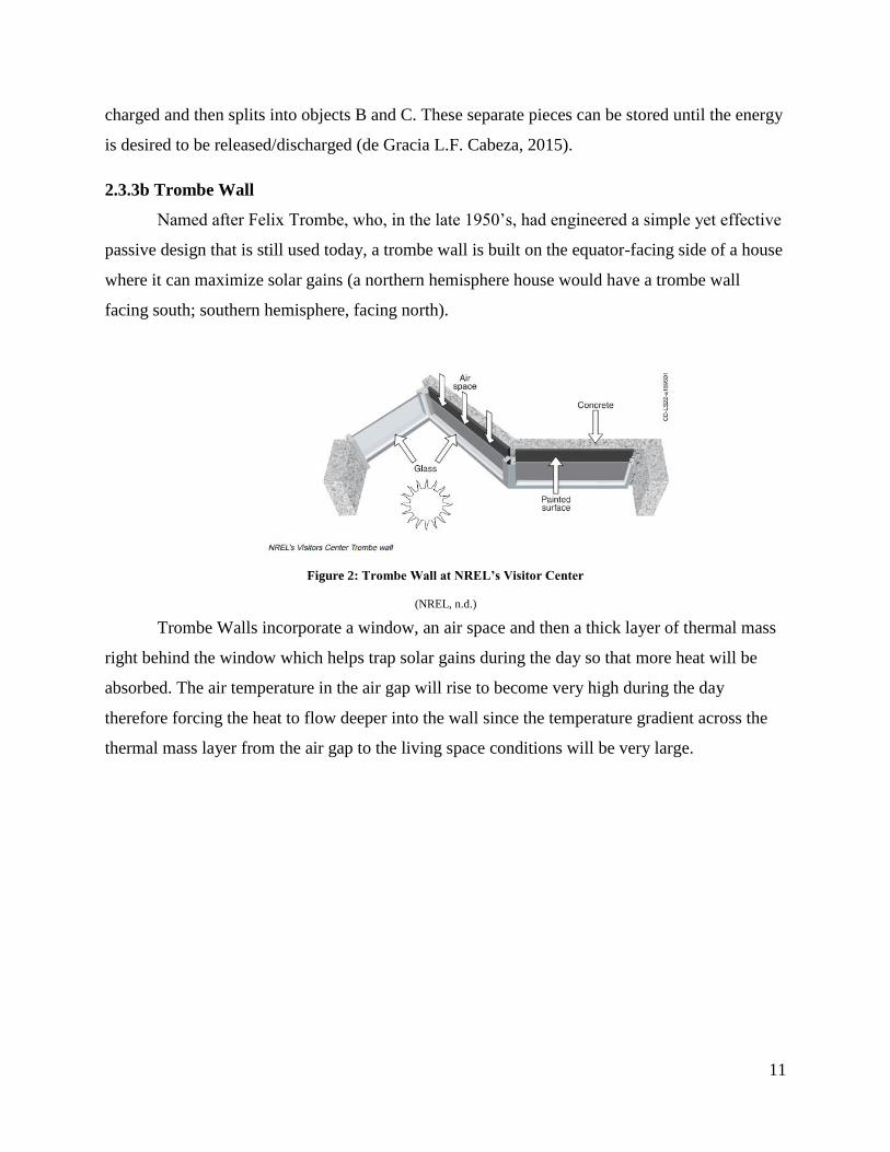
Figure 3: Northern Hemisphere Trombe Wall Schematic
(NREL, n.d.)
A passive air flow will occur within the wall naturally with a high wall vent and a low
wall vent, as seen in Figure 3. As air is heated within the air gap it will rise and create a natural
convective flow that will suck in cooler air from the living space and expel it back into the space
as warmer air while the excess heat will be absorbed into the wall. During the night the thermal
mass layer will slowly release its stored solar heat from the day’s sunlight into the living space
(NREL, n.d.).
Proper shading and reflective glazing can optimize this design so that there is no heating
effect in the summer, when it is desirable to cool the space. In the summer, when the sun is
higher in the sky, an overhang can block the sunlight from warming the wall and the use of
reflective glazing in the windows can make the sunlight bounce off the window to eliminate heat
gain (NREL, n.d.).
2.3.3c Water Wall
Water is twice as effective at storing thermal energy as concrete, and 4800 times better
than air. The thermal energy stored in the Earth’s oceans work as a giant thermal battery to keep
13
temperature ranges on the planet within the optimal range. A water wall is a wall made of large
tanks of water placed behind an area of windows facing the equator-direction (south for northern
hemisphere buildings, north for southern hemisphere buildings) where the water is able to absorb
and store heat collected from the sun. The heated water can then be used to circulate the air
within a home by forcing air from the living space through the water in the tanks and then back
into the living space. Alternatively, the home could be heated by using a fan to blow over the
exterior of the tanks to disseminate the heat from the tanks into the home (Bainbridge, 2005).
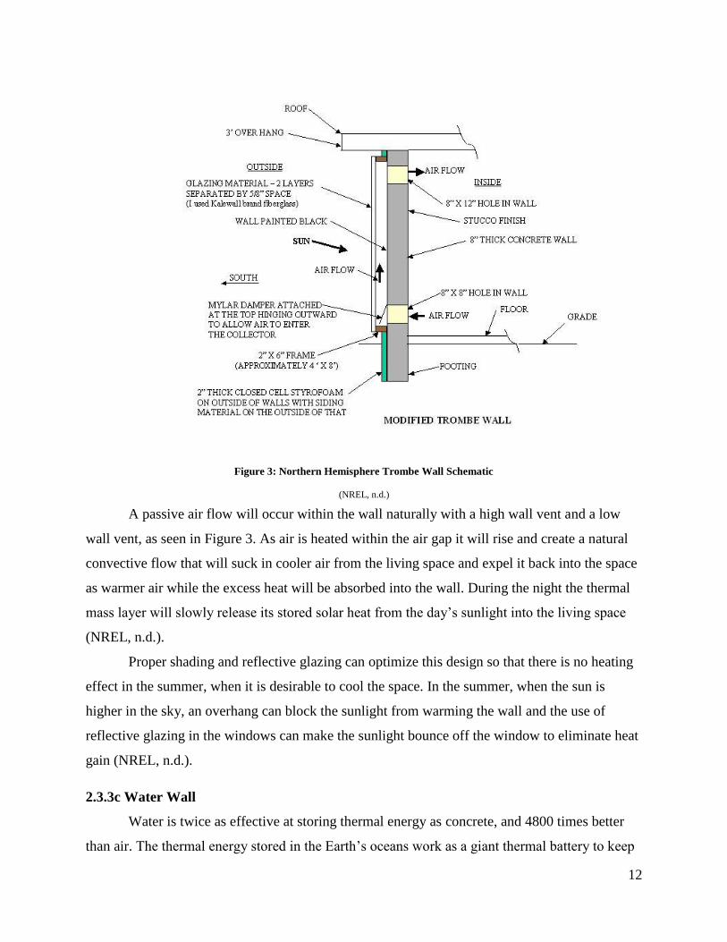
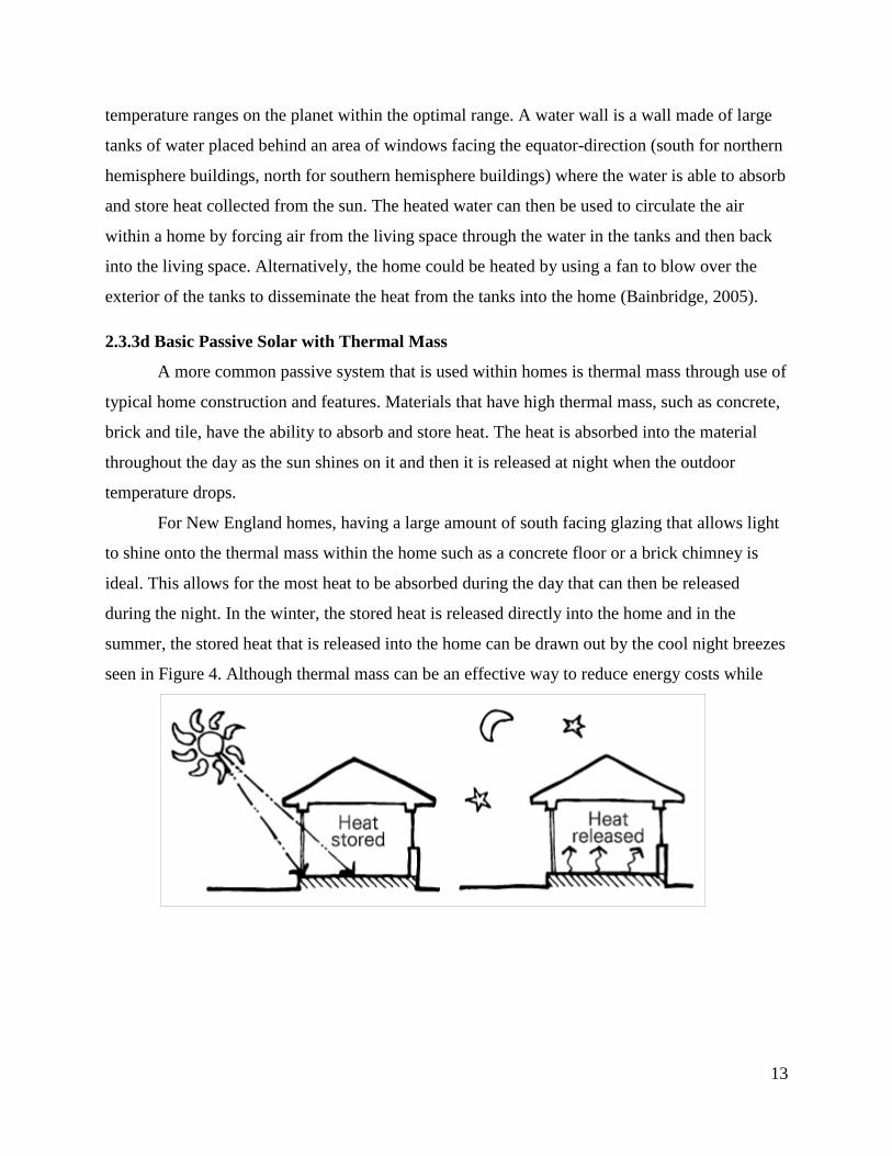
2.3.3d Basic Passive Solar with Thermal Mass
A more common passive system that is used within homes is thermal mass through use of
typical home construction and features. Materials that have high thermal mass, such as concrete,
brick and tile, have the ability to absorb and store heat. The heat is absorbed into the material
throughout the day as the sun shines on it and then it is released at night when the outdoor
temperature drops.
For New England homes, having a large amount of south facing glazing that allows light
to shine onto the thermal mass within the home such as a concrete floor or a brick chimney is
ideal. This allows for the most heat to be absorbed during the day that can then be released
during the night. In the winter, the stored heat is released directly into the home and in the
summer, the stored heat that is released into the home can be drawn out by the cool night breezes
seen in Figure 4. Although thermal mass can be an effective way to reduce energy costs while
14
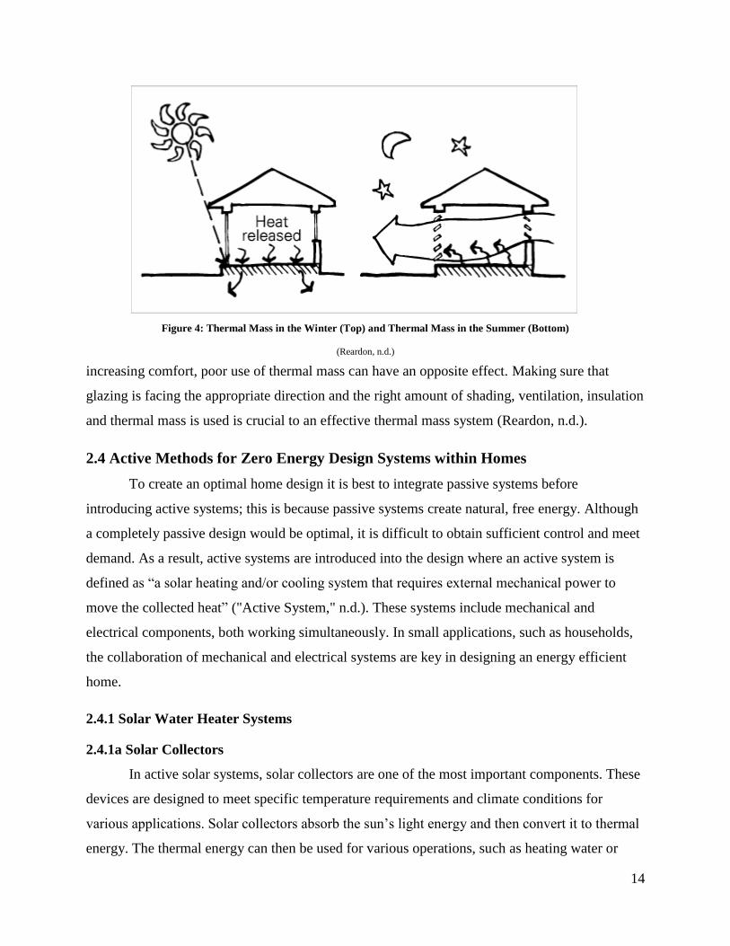
Figure 4: Thermal Mass in the Winter (Top) and Thermal Mass in the Summer (Bottom)
(Reardon, n.d.)
increasing comfort, poor use of thermal mass can have an opposite effect. Making sure that
glazing is facing the appropriate direction and the right amount of shading, ventilation, insulation
and thermal mass is used is crucial to an effective thermal mass system (Reardon, n.d.).
2.4 Active Methods for Zero Energy Design Systems within Homes
To create an optimal home design it is best to integrate passive systems before
introducing active systems; this is because passive systems create natural, free energy. Although
a completely passive design would be optimal, it is difficult to obtain sufficient control and meet
demand. As a result, active systems are introduced into the design where an active system is
defined as “a solar heating and/or cooling system that requires external mechanical power to
move the collected heat” ("Active System," n.d.). These systems include mechanical and
electrical components, both working simultaneously. In small applications, such as households,
the collaboration of mechanical and electrical systems are key in designing an energy efficient
home.
2.4.1 Solar Water Heater Systems
2.4.1a Solar Collectors
In active solar systems, solar collectors are one of the most important components. These
devices are designed to meet specific temperature requirements and climate conditions for
various applications. Solar collectors absorb the sun’s light energy and then convert it to thermal
energy. The thermal energy can then be used for various operations, such as heating water or
15
providing space heating or cooling ("Active Solar Systems," n.d.). There are various types of
solar collectors on the market, but the most common are flat-plate and evacuated tube collectors.
Flat-plate collectors are the most common solar thermal systems for water and space
heating. The typical configuration of a flat-plate collector looks very similar to an oversized
skylight; the casing is typically made out of an insulated metal box with a glass or plastic cover,
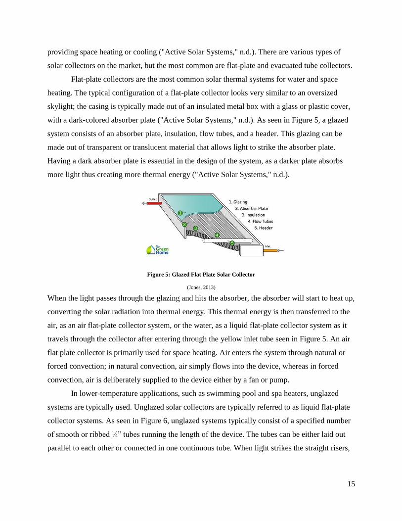
with a dark-colored absorber plate ("Active Solar Systems," n.d.). As seen in Figure 5, a glazed
system consists of an absorber plate, insulation, flow tubes, and a header. This glazing can be
made out of transparent or translucent material that allows light to strike the absorber plate.
Having a dark absorber plate is essential in the design of the system, as a darker plate absorbs
more light thus creating more thermal energy ("Active Solar Systems," n.d.).
Figure 5: Glazed Flat Plate Solar Collector
(Jones, 2013)
When the light passes through the glazing and hits the absorber, the absorber will start to heat up,
converting the solar radiation into thermal energy. This thermal energy is then transferred to the
air, as an air flat-plate collector system, or the water, as a liquid flat-plate collector system as it
travels through the collector after entering through the yellow inlet tube seen in Figure 5. An air
flat plate collector is primarily used for space heating. Air enters the system through natural or
forced convection; in natural convection, air simply flows into the device, whereas in forced
convection, air is deliberately supplied to the device either by a fan or pump.
In lower-temperature applications, such as swimming pool and spa heaters, unglazed
systems are typically used. Unglazed solar collectors are typically referred to as liquid flat-plate
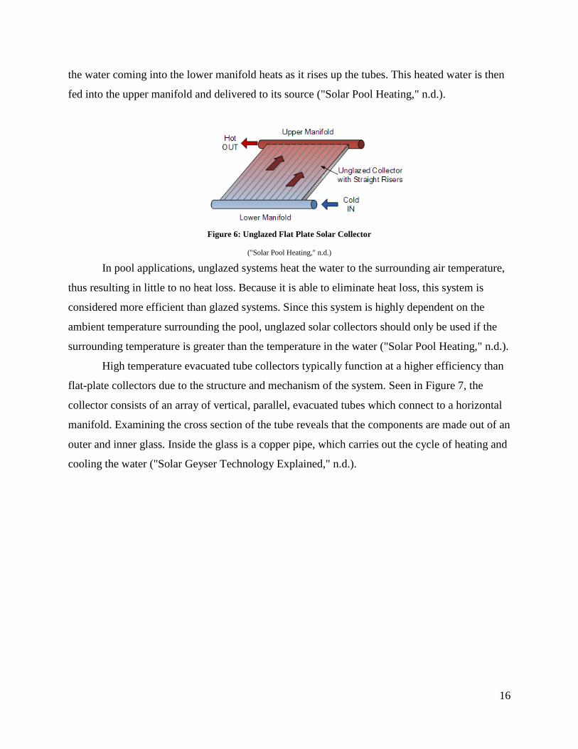
collector systems. As seen in Figure 6, unglazed systems typically consist of a specified number
of smooth or ribbed ¼” tubes running the length of the device. The tubes can be either laid out
parallel to each other or connected in one continuous tube. When light strikes the straight risers,
16
the water coming into the lower manifold heats as it rises up the tubes. This heated water is then
fed into the upper manifold and delivered to its source ("Solar Pool Heating," n.d.).
Figure 6: Unglazed Flat Plate Solar Collector
("Solar Pool Heating," n.d.)
In pool applications, unglazed systems heat the water to the surrounding air temperature,
thus resulting in little to no heat loss. Because it is able to eliminate heat loss, this system is
considered more efficient than glazed systems. Since this system is highly dependent on the
ambient temperature surrounding the pool, unglazed solar collectors should only be used if the
surrounding temperature is greater than the temperature in the water ("Solar Pool Heating," n.d.).
High temperature evacuated tube collectors typically function at a higher efficiency than
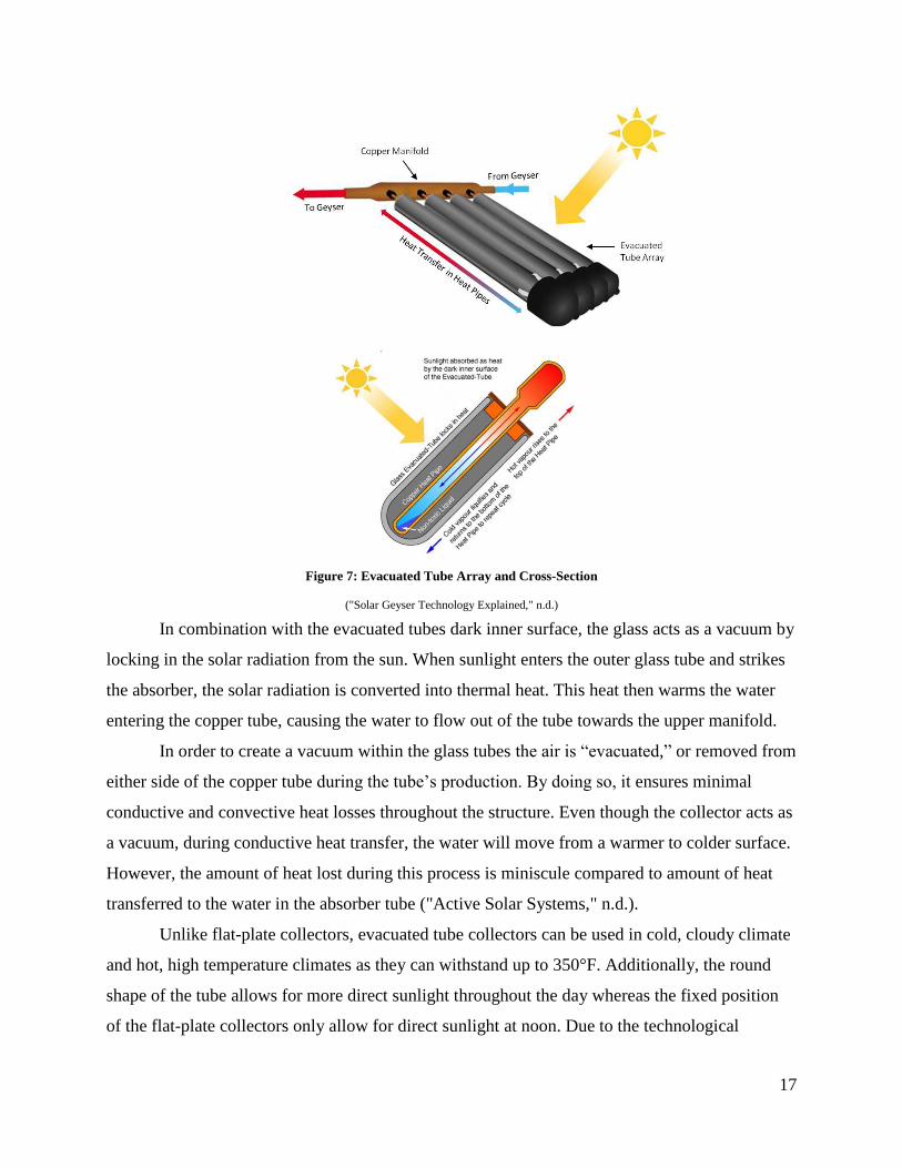
flat-plate collectors due to the structure and mechanism of the system. Seen in Figure 7, the
collector consists of an array of vertical, parallel, evacuated tubes which connect to a horizontal
manifold. Examining the cross section of the tube reveals that the components are made out of an
outer and inner glass. Inside the glass is a copper pipe, which carries out the cycle of heating and
cooling the water ("Solar Geyser Technology Explained," n.d.).
17
Figure 7: Evacuated Tube Array and Cross-Section
("Solar Geyser Technology Explained," n.d.)
In combination with the evacuated tubes dark inner surface, the glass acts as a vacuum by
locking in the solar radiation from the sun. When sunlight enters the outer glass tube and strikes
the absorber, the solar radiation is converted into thermal heat. This heat then warms the water
entering the copper tube, causing the water to flow out of the tube towards the upper manifold.
In order to create a vacuum within the glass tubes the air is “evacuated,” or removed from
either side of the copper tube during the tube’s production. By doing so, it ensures minimal
conductive and convective heat losses throughout the structure. Even though the collector acts as
a vacuum, during conductive heat transfer, the water will move from a warmer to colder surface.
However, the amount of heat lost during this process is miniscule compared to amount of heat
transferred to the water in the absorber tube ("Active Solar Systems," n.d.).
Unlike flat-plate collectors, evacuated tube collectors can be used in cold, cloudy climate
and hot, high temperature climates as they can withstand up to 350°F. Additionally, the round
shape of the tube allows for more direct sunlight throughout the day whereas the fixed position
of the flat-plate collectors only allow for direct sunlight at noon. Due to the technological
18
advances present in evacuated tube collectors, they tend to be more expensive than flat-plate
collectors ("Active Solar Systems," n.d.).
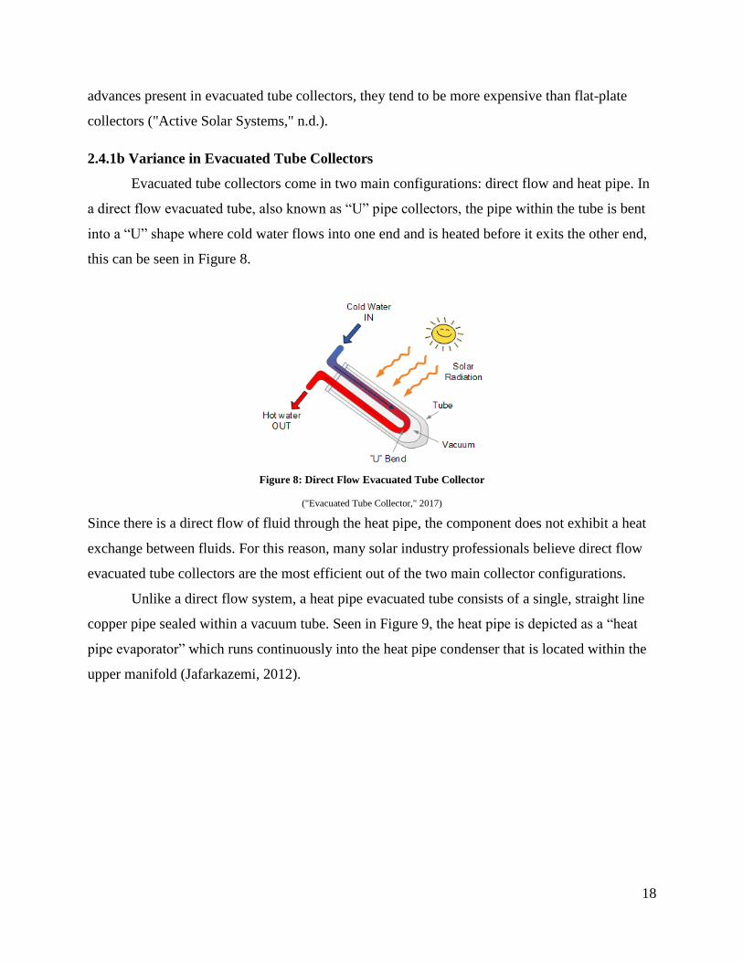
2.4.1b Variance in Evacuated Tube Collectors
Evacuated tube collectors come in two main configurations: direct flow and heat pipe. In
a direct flow evacuated tube, also known as “U” pipe collectors, the pipe within the tube is bent
into a “U” shape where cold water flows into one end and is heated before it exits the other end,
this can be seen in Figure 8.
Figure 8: Direct Flow Evacuated Tube Collector
("Evacuated Tube Collector," 2017)
Since there is a direct flow of fluid through the heat pipe, the component does not exhibit a heat
exchange between fluids. For this reason, many solar industry professionals believe direct flow
evacuated tube collectors are the most efficient out of the two main collector configurations.
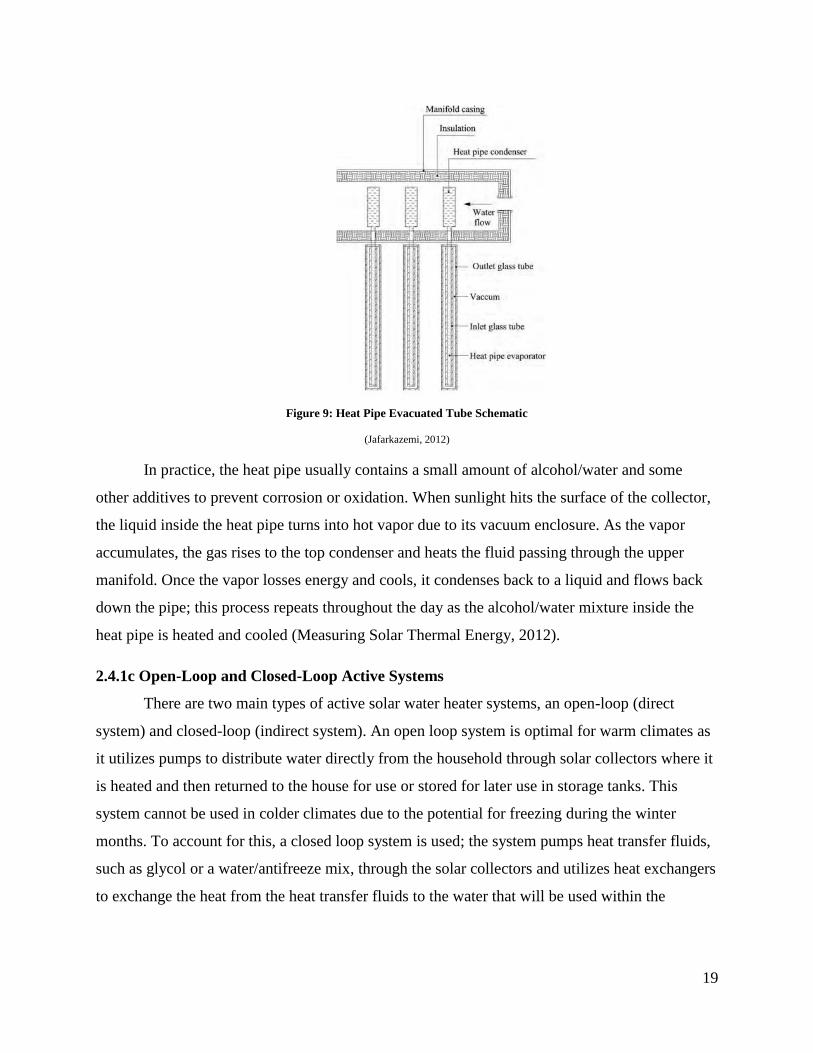
Unlike a direct flow system, a heat pipe evacuated tube consists of a single, straight line
copper pipe sealed within a vacuum tube. Seen in Figure 9, the heat pipe is depicted as a “heat
pipe evaporator” which runs continuously into the heat pipe condenser that is located within the
upper manifold (Jafarkazemi, 2012).
19
Figure 9: Heat Pipe Evacuated Tube Schematic
(Jafarkazemi, 2012)
In practice, the heat pipe usually contains a small amount of alcohol/water and some
other additives to prevent corrosion or oxidation. When sunlight hits the surface of the collector,
the liquid inside the heat pipe turns into hot vapor due to its vacuum enclosure. As the vapor
accumulates, the gas rises to the top condenser and heats the fluid passing through the upper
manifold. Once the vapor losses energy and cools, it condenses back to a liquid and flows back
down the pipe; this process repeats throughout the day as the alcohol/water mixture inside the
heat pipe is heated and cooled (Measuring Solar Thermal Energy, 2012).
2.4.1c Open-Loop and Closed-Loop Active Systems
There are two main types of active solar water heater systems, an open-loop (direct
system) and closed-loop (indirect system). An open loop system is optimal for warm climates as
it utilizes pumps to distribute water directly from the household through solar collectors where it
is heated and then returned to the house for use or stored for later use in storage tanks. This
system cannot be used in colder climates due to the potential for freezing during the winter
months. To account for this, a closed loop system is used; the system pumps heat transfer fluids,
such as glycol or a water/antifreeze mix, through the solar collectors and utilizes heat exchangers
to exchange the heat from the heat transfer fluids to the water that will be used within the
20
household. This heated water is then stored within a storage tank until it is ready for use ("Active
Solar Systems, " n.d.).
Direct systems can be operated by either natural or forced convection. A natural
convection, or thermosiphon system, works by drawing cold water through the solar collector
while moving hot water from the collector into the storage tanks. Although this system has been
proven to be simple and inexpensive, it does create two major disadvantages. First, since the
system operates under natural convection, the storage tanks would need to be located at a higher
point than the solar collector; which in most cases is difficult to accomplish. Second, in order for
the system to work there must be water within the collector at all times leading to the possibility
of freezing. In forced convection, the water circulates between the collector and the storage tank
using a pump. Because the pump has the ability to be turned on and off it allows the solar
collector to only operate when there is enough solar radiation to produce useful heat.
Additionally, forced convection systems allow the water to be discharged by gravity flow from
the collector, known as a “draindown”, to avoid freezing ("Active Solar Systems," n.d.).
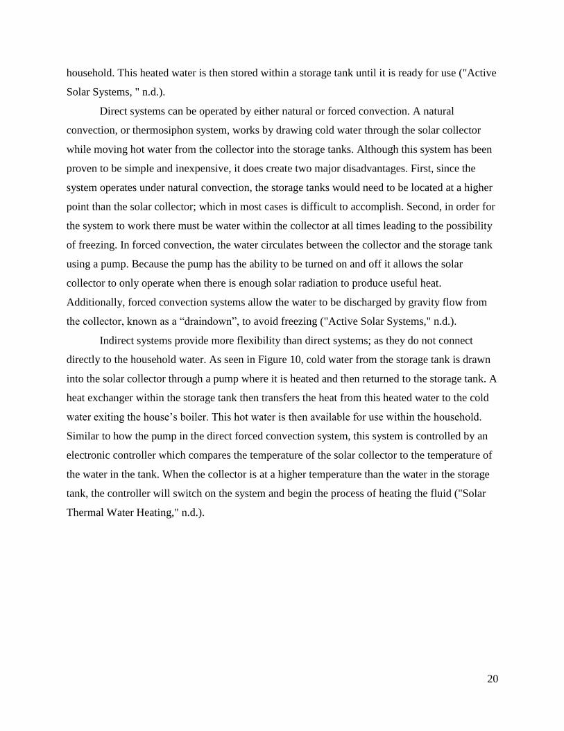
Indirect systems provide more flexibility than direct systems; as they do not connect
directly to the household water. As seen in Figure 10, cold water from the storage tank is drawn
into the solar collector through a pump where it is heated and then returned to the storage tank. A
heat exchanger within the storage tank then transfers the heat from this heated water to the cold
water exiting the house’s boiler. This hot water is then available for use within the household.
Similar to how the pump in the direct forced convection system, this system is controlled by an
electronic controller which compares the temperature of the solar collector to the temperature of
the water in the tank. When the collector is at a higher temperature than the water in the storage
tank, the controller will switch on the system and begin the process of heating the fluid ("Solar
Thermal Water Heating," n.d.).
21
Figure 10: Indirect Solar Water Heater System
("Solar Thermal Water Heating," n.d.)
To protect this system from freezing or corroding, solutions can be added to the liquid circulating
through the solar collector, such as antifreeze, which allows the system to run year round without
having to drain the system ("Active Solar Systems," n.d.).
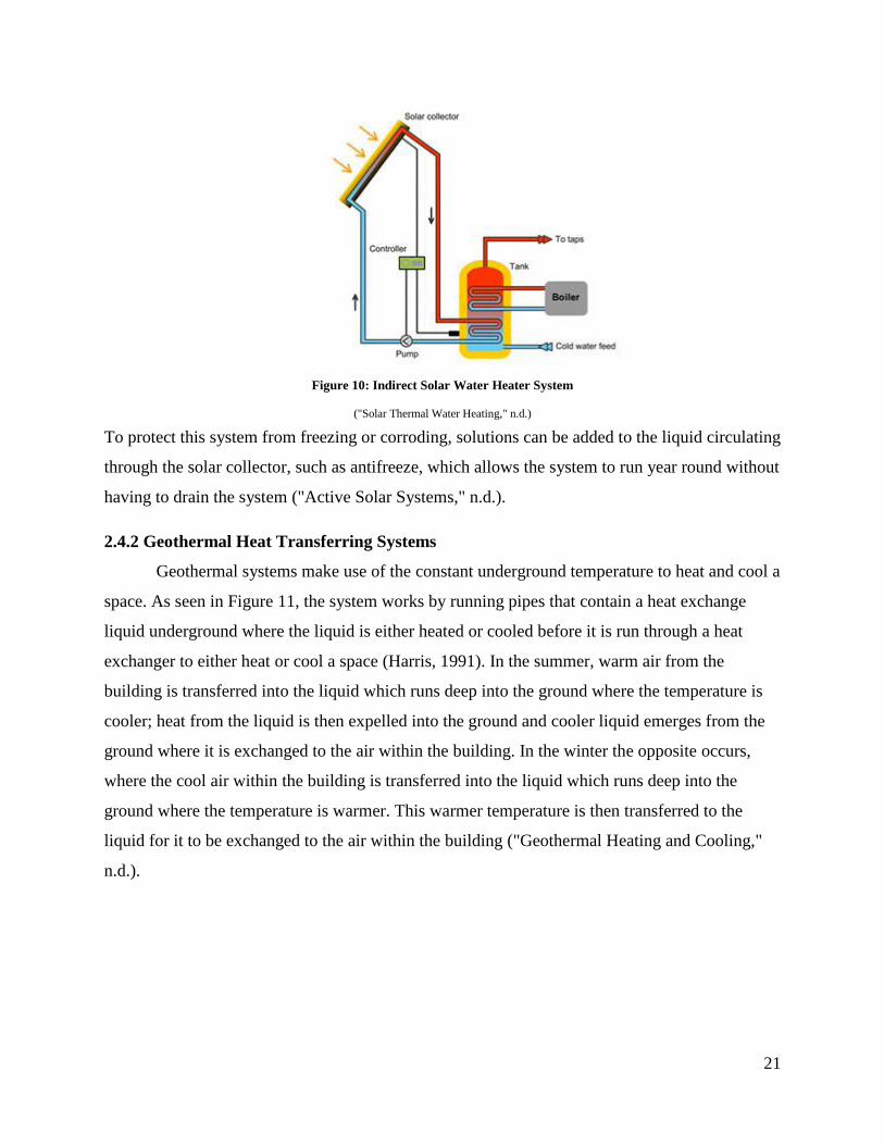
2.4.2 Geothermal Heat Transferring Systems
Geothermal systems make use of the constant underground temperature to heat and cool a
space. As seen in Figure 11, the system works by running pipes that contain a heat exchange
liquid underground where the liquid is either heated or cooled before it is run through a heat
exchanger to either heat or cool a space (Harris, 1991). In the summer, warm air from the
building is transferred into the liquid which runs deep into the ground where the temperature is
cooler; heat from the liquid is then expelled into the ground and cooler liquid emerges from the
ground where it is exchanged to the air within the building. In the winter the opposite occurs,
where the cool air within the building is transferred into the liquid which runs deep into the
ground where the temperature is warmer. This warmer temperature is then transferred to the
liquid for it to be exchanged to the air within the building ("Geothermal Heating and Cooling,"
n.d.).
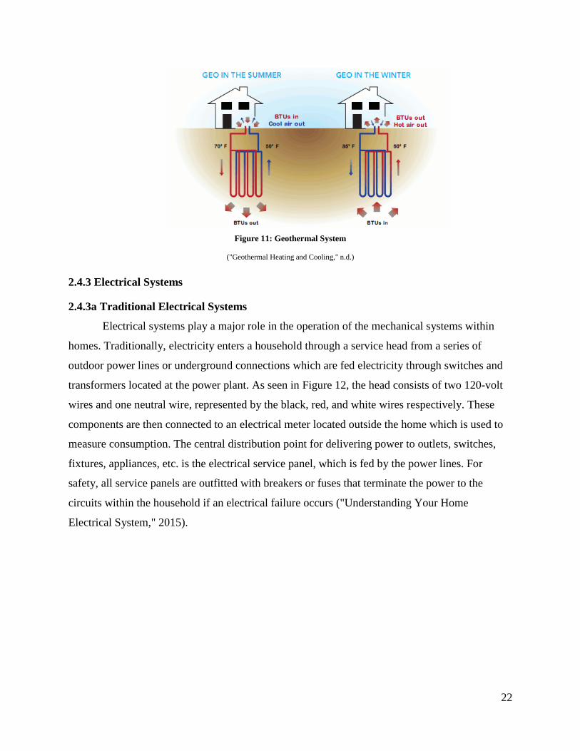
22
Figure 11: Geothermal System
("Geothermal Heating and Cooling," n.d.)
2.4.3 Electrical Systems
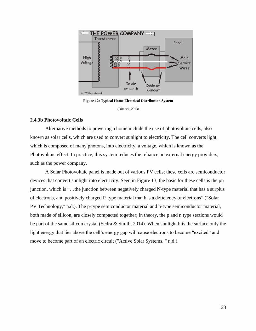
2.4.3a Traditional Electrical Systems
Electrical systems play a major role in the operation of the mechanical systems within
homes. Traditionally, electricity enters a household through a service head from a series of
outdoor power lines or underground connections which are fed electricity through switches and
transformers located at the power plant. As seen in Figure 12, the head consists of two 120-volt
wires and one neutral wire, represented by the black, red, and white wires respectively. These
components are then connected to an electrical meter located outside the home which is used to
measure consumption. The central distribution point for delivering power to outlets, switches,
fixtures, appliances, etc. is the electrical service panel, which is fed by the power lines. For
safety, all service panels are outfitted with breakers or fuses that terminate the power to the
circuits within the household if an electrical failure occurs ("Understanding Your Home
Electrical System," 2015).
23
Figure 12: Typical Home Electrical Distribution System
(Dimock, 2013)
2.4.3b Photovoltaic Cells
Alternative methods to powering a home include the use of photovoltaic cells, also
known as solar cells, which are used to convert sunlight to electricity. The cell converts light,
which is composed of many photons, into electricity, a voltage, which is known as the
Photovoltaic effect. In practice, this system reduces the reliance on external energy providers,
such as the power company.
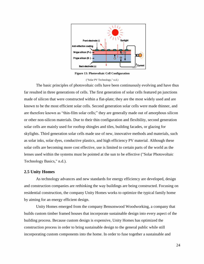
A Solar Photovoltaic panel is made out of various PV cells; these cells are semiconductor
devices that convert sunlight into electricity. Seen in Figure 13, the basis for these cells is the pn
junction, which is “…the junction between negatively charged N-type material that has a surplus
of electrons, and positively charged P-type material that has a deficiency of electrons” ("Solar
PV Technology," n.d.). The p-type semiconductor material and n-type semiconductor material,
both made of silicon, are closely compacted together; in theory, the p and n type sections would
be part of the same silicon crystal (Sedra & Smith, 2014). When sunlight hits the surface only the
light energy that lies above the cell’s energy gap will cause electrons to become “excited” and
move to become part of an electric circuit ("Active Solar Systems, " n.d.).
24
Figure 13: Photovoltaic Cell Configuration
("Solar PV Technology," n.d.)
The basic principles of photovoltaic cells have been continuously evolving and have thus
far resulted in three generations of cells. The first generation of solar cells featured pn junctions
made of silicon that were constructed within a flat-plate; they are the most widely used and are
known to be the most efficient solar cells. Second generation solar cells were made thinner, and
are therefore known as “thin-film solar cells;” they are generally made out of amorphous silicon
or other non-silicon materials. Due to their thin configuration and flexibility, second generation
solar cells are mainly used for rooftop shingles and tiles, building facades, or glazing for
skylights. Third generation solar cells made use of new, innovative methods and materials, such
as solar inks, solar dyes, conductive plastics, and high efficiency PV material. Although these
solar cells are becoming more cost effective, use is limited to certain parts of the world as the
lenses used within the systems must be pointed at the sun to be effective ("Solar Photovoltaic
Technology Basics," n.d.).
2.5 Unity Homes
As technology advances and new standards for energy efficiency are developed, design
and construction companies are rethinking the way buildings are being constructed. Focusing on
residential construction, the company Unity Homes works to optimize the typical family home
by aiming for an energy efficient design.
Unity Homes emerged from the company Bensonwood Woodworking, a company that
builds custom timber framed houses that incorporate sustainable design into every aspect of the
building process. Because custom design is expensive, Unity Homes has optimized the
construction process in order to bring sustainable design to the general public while still
incorporating custom components into the home. In order to fuse together a sustainable and
25
custom design, Unity Homes has introduced construction techniques, materials and systems that
differ from traditional building design and construction.
2.5.1 Design
Unlike a typical detached residential home which is designed by an architect, Unity
Homes houses are built using an Open-Built® system. Developed in collaboration with a Dutch
architect John Habraken, “Open-Built® is a way of approaching home design that looks at the
function and usable life of six distinct interconnected layers: site, structure, skin, space plan,
systems and ‘stuff ’” ("A Better Way to Build," n.d.). In addition to focusing on these six layers,
Unity Homes designs its structures on a 2’ grid, referred to as an OBGrid, which allows for
consistent structural and aesthetic integrity as well as making it simple to build additions in the
future. Finally, Unity Homes simplifies the process by providing homebuyers with four different
starting points, called platforms, which will provide them with a unique home built within a
shorter time frame and at a lower cost than typical new construction homes ("A Better Way to
Build," n.d.).
While the four platforms allow Unity Homes to speed up the process of both the design
and construction, they can also be slightly altered to meet the needs of the homeowner. The
Tradd, an abbreviation for “tradition,” is the most expensive of the four platforms with a base
price of $325,000. The home is designed to resemble a classic New England “Cape” style house
that has two stories and seven different sets of possible floor plans each with different numbers
of bedrooms and bathrooms. They also include optional features such as screened porches,
various entry styles, attached garages and one-level connectors. The platform can be built with 2-
4 bedrooms and 2.5-3.5 bathrooms with a total area of 1750-2800 square feet and is best suited
to feature exposed timber framing throughout the home ("A Better Way to Build," n.d.).
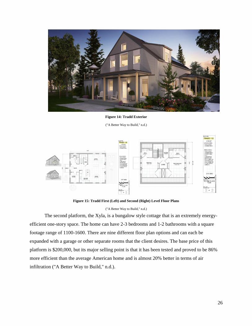
26
Figure 14: Tradd Exterior
("A Better Way to Build," n.d.)
Figure 15: Tradd First (Left) and Second (Right) Level Floor Plans
("A Better Way to Build," n.d.)
The second platform, the Xyla, is a bungalow style cottage that is an extremely energy-
efficient one-story space. The home can have 2-3 bedrooms and 1-2 bathrooms with a square
footage range of 1100-1600. There are nine different floor plan options and can each be
expanded with a garage or other separate rooms that the client desires. The base price of this
platform is $200,000, but its major selling point is that it has been tested and proved to be 86%
more efficient than the average American home and is almost 20% better in terms of air
infiltration ("A Better Way to Build," n.d.).
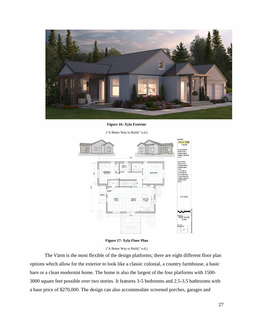
27
Figure 16: Xyla Exterior
("A Better Way to Build," n.d.)
Figure 17: Xyla Floor Plan
("A Better Way to Build," n.d.)
The Värm is the most flexible of the design platforms; there are eight different floor plan
options which allow for the exterior to look like a classic colonial, a country farmhouse, a basic
barn or a clean modernist home. The home is also the largest of the four platforms with 1500-
3000 square feet possible over two stories. It features 3-5 bedrooms and 2.5-3.5 bathrooms with
a base price of $270,000. The design can also accommodate screened porches, garages and
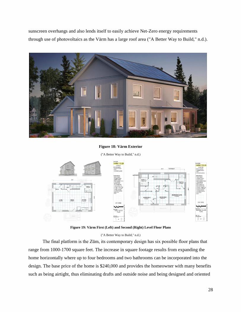
28
sunscreen overhangs and also lends itself to easily achieve Net-Zero energy requirements
through use of photovoltaics as the Värm has a large roof area ("A Better Way to Build," n.d.).
Figure 18: Värm Exterior
("A Better Way to Build," n.d.)
Figure 19: Värm First (Left) and Second (Right) Level Floor Plans
("A Better Way to Build," n.d.)
The final platform is the Zūm, its contemporary design has six possible floor plans that
range from 1000-1700 square feet. The increase in square footage results from expanding the
home horizontally where up to four bedrooms and two bathrooms can be incorporated into the
design. The base price of the home is $240,000 and provides the homeowner with many benefits
such as being airtight, thus eliminating drafts and outside noise and being designed and oriented
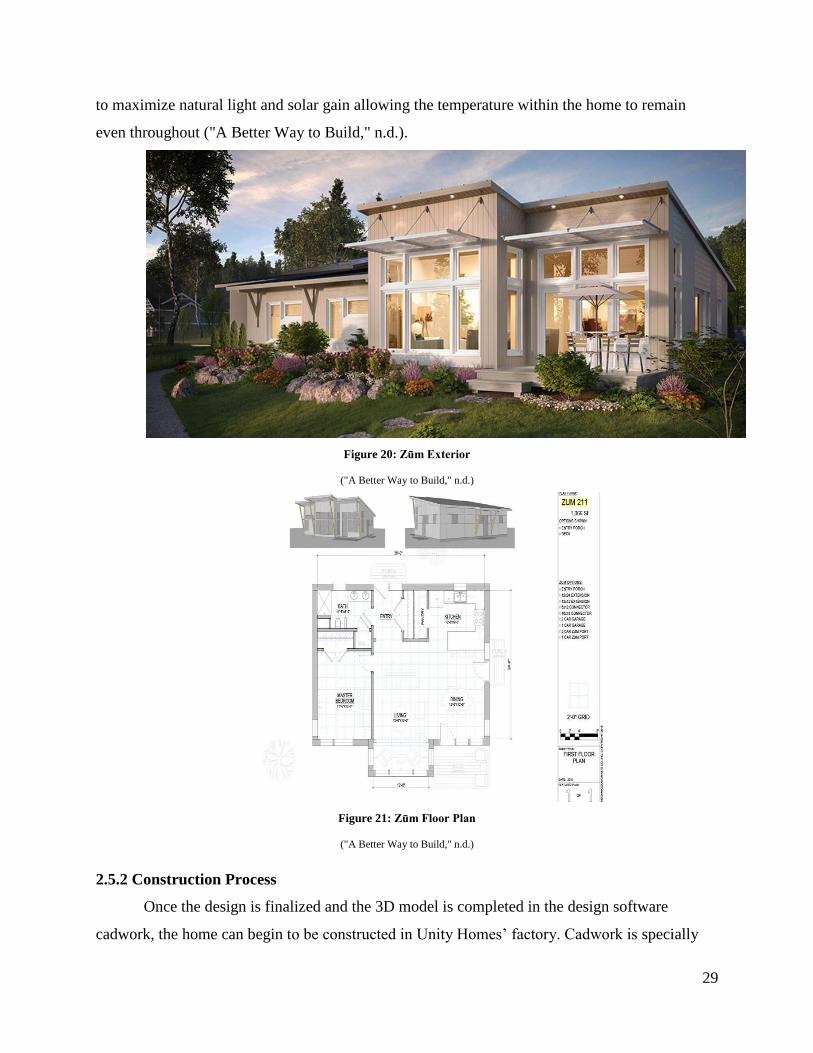
29
to maximize natural light and solar gain allowing the temperature within the home to remain
even throughout ("A Better Way to Build," n.d.).
Figure 20: Zūm Exterior
("A Better Way to Build," n.d.)
Figure 21: Zūm Floor Plan
("A Better Way to Build," n.d.)
2.5.2 Construction Process
Once the design is finalized and the 3D model is completed in the design software
cadwork, the home can begin to be constructed in Unity Homes’ factory. Cadwork is specially
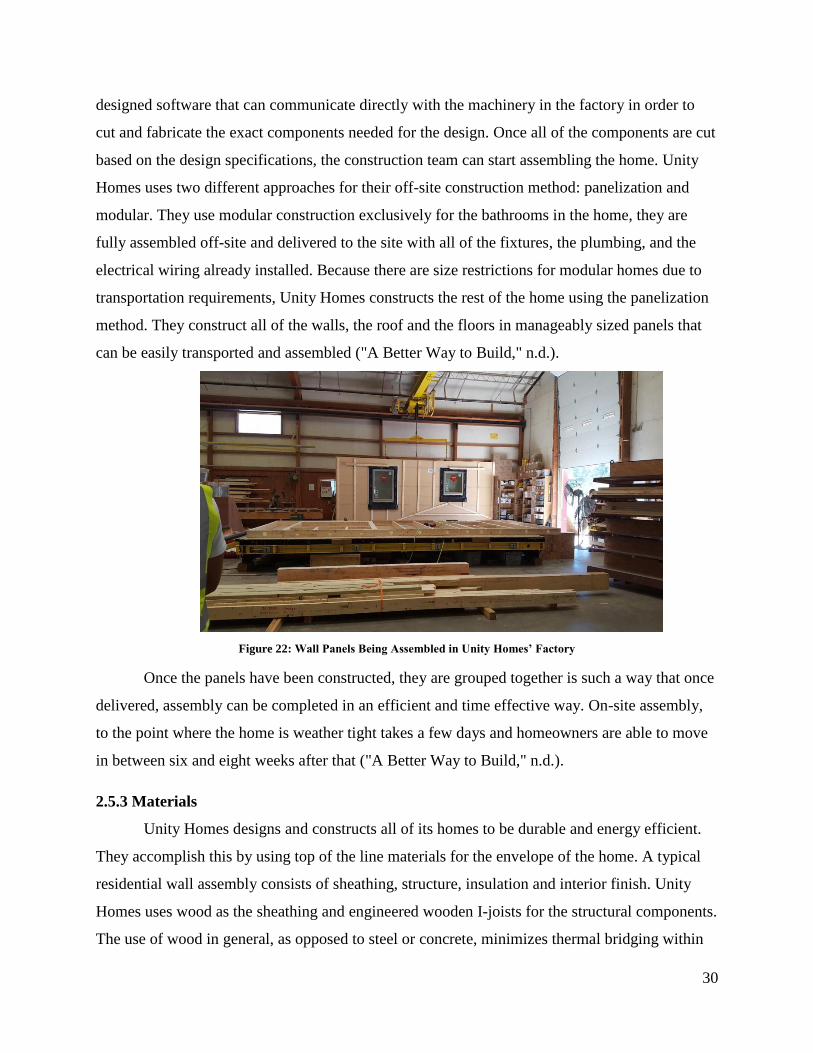
30
designed software that can communicate directly with the machinery in the factory in order to
cut and fabricate the exact components needed for the design. Once all of the components are cut
based on the design specifications, the construction team can start assembling the home. Unity
Homes uses two different approaches for their off-site construction method: panelization and
modular. They use modular construction exclusively for the bathrooms in the home, they are
fully assembled off-site and delivered to the site with all of the fixtures, the plumbing, and the
electrical wiring already installed. Because there are size restrictions for modular homes due to
transportation requirements, Unity Homes constructs the rest of the home using the panelization
method. They construct all of the walls, the roof and the floors in manageably sized panels that
can be easily transported and assembled ("A Better Way to Build," n.d.).
Figure 22: Wall Panels Being Assembled in Unity Homes’ Factory
Once the panels have been constructed, they are grouped together is such a way that once
delivered, assembly can be completed in an efficient and time effective way. On-site assembly,
to the point where the home is weather tight takes a few days and homeowners are able to move
in between six and eight weeks after that ("A Better Way to Build," n.d.).
2.5.3 Materials
Unity Homes designs and constructs all of its homes to be durable and energy efficient.
They accomplish this by using top of the line materials for the envelope of the home. A typical
residential wall assembly consists of sheathing, structure, insulation and interior finish. Unity
Homes uses wood as the sheathing and engineered wooden I-joists for the structural components.
The use of wood in general, as opposed to steel or concrete, minimizes thermal bridging within
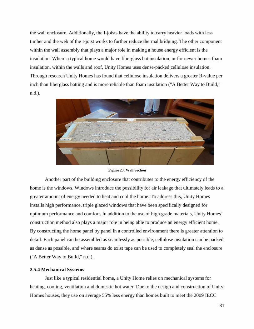
31
the wall enclosure. Additionally, the I-joists have the ability to carry heavier loads with less
timber and the web of the I-joist works to further reduce thermal bridging. The other component
within the wall assembly that plays a major role in making a house energy efficient is the
insulation. Where a typical home would have fiberglass bat insulation, or for newer homes foam
insulation, within the walls and roof, Unity Homes uses dense-packed cellulose insulation.
Through research Unity Homes has found that cellulose insulation delivers a greater R-value per
inch than fiberglass batting and is more reliable than foam insulation ("A Better Way to Build,"
n.d.).
Figure 23: Wall Section
Another part of the building enclosure that contributes to the energy efficiency of the
home is the windows. Windows introduce the possibility for air leakage that ultimately leads to a
greater amount of energy needed to heat and cool the home. To address this, Unity Homes
installs high performance, triple glazed windows that have been specifically designed for
optimum performance and comfort. In addition to the use of high grade materials, Unity Homes’
construction method also plays a major role in being able to produce an energy efficient home.
By constructing the home panel by panel in a controlled environment there is greater attention to
detail. Each panel can be assembled as seamlessly as possible, cellulose insulation can be packed
as dense as possible, and where seams do exist tape can be used to completely seal the enclosure
("A Better Way to Build," n.d.).
2.5.4 Mechanical Systems
Just like a typical residential home, a Unity Home relies on mechanical systems for
heating, cooling, ventilation and domestic hot water. Due to the design and construction of Unity
Homes houses, they use on average 55% less energy than homes built to meet the 2009 IECC
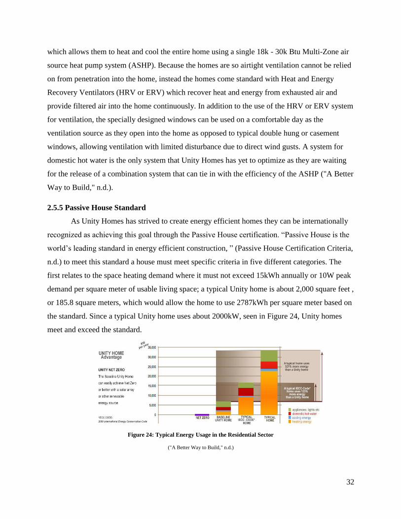
32
which allows them to heat and cool the entire home using a single 18k - 30k Btu Multi-Zone air
source heat pump system (ASHP). Because the homes are so airtight ventilation cannot be relied
on from penetration into the home, instead the homes come standard with Heat and Energy
Recovery Ventilators (HRV or ERV) which recover heat and energy from exhausted air and
provide filtered air into the home continuously. In addition to the use of the HRV or ERV system
for ventilation, the specially designed windows can be used on a comfortable day as the
ventilation source as they open into the home as opposed to typical double hung or casement
windows, allowing ventilation with limited disturbance due to direct wind gusts. A system for
domestic hot water is the only system that Unity Homes has yet to optimize as they are waiting
for the release of a combination system that can tie in with the efficiency of the ASHP ("A Better
Way to Build," n.d.).
2.5.5 Passive House Standard
As Unity Homes has strived to create energy efficient homes they can be internationally
recognized as achieving this goal through the Passive House certification. “Passive House is the
world’s leading standard in energy efficient construction, ” (Passive House Certification Criteria,
n.d.) to meet this standard a house must meet specific criteria in five different categories. The
first relates to the space heating demand where it must not exceed 15kWh annually or 10W peak
demand per square meter of usable living space; a typical Unity home is about 2,000 square feet ,
or 185.8 square meters, which would allow the home to use 2787kWh per square meter based on
the standard. Since a typical Unity home uses about 2000kW, seen in Figure 24, Unity homes
meet and exceed the standard.
Figure 24: Typical Energy Usage in the Residential Sector
("A Better Way to Build," n.d.)
33
The second category relates to cooling where the space cooling demand must also not
exceed 15kWh annually or 10W peak demand per square meter of usable living space, but is
allowed additional use for dehumidification depending on the climate; a typical Unity home
however uses a fraction of that as seen in Figure 24. The third category details the primary
energy demand where all domestic applications, namely heating, cooling, hot water and
electricity, must not exceed 120kWh annually. From Figure 24 it can be seen that the total
energy usage is approximately 7000kWh which is much less than the allowable amount of over
22,000 based on the standard. The fourth category has to do with air tightness where there must
be a maximum of .6 air changes per hour at 50 Pascals of pressure. A typical Unity home ranges
from .5 to .7 air changes per hour at 50 Pascals of pressure; although Unity is able to meet the
standard, this suggests that there is some room for improvement. The final category relates to
thermal comfort where not more than 10% of hours in a year can the indoor temperature exceed
25 degrees Celsius, or 77 degrees Fahrenheit (Passive House Certification Criteria, n.d.).
Although the indoor air temperature is ultimately determined by the occupants, when tests were
conducted on Unity homes the design temperatures used were 70 degrees Fahrenheit for heating
and at most 75 degrees Fahrenheit for cooling. Overall, Unity Homes has been very successful in
terms of being able to meet the international passive house standard through its high quality
products, impressive designs and exceptional construction methods. Although the company has
met such a high standard, there is still room for improvement in terms of air tightness and a low
energy combination heating, cooling, ventilation and domestic hot water system on the quest to
achieve a net zero energy home.
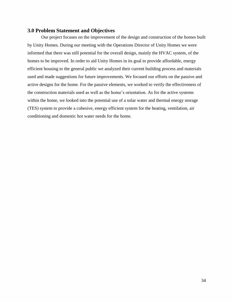
34
3.0 Problem Statement and Objectives
Our project focuses on the improvement of the design and construction of the homes built
by Unity Homes. During our meeting with the Operations Director of Unity Homes we were
informed that there was still potential for the overall design, mainly the HVAC system, of the
homes to be improved. In order to aid Unity Homes in its goal to provide affordable, energy
efficient housing to the general public we analyzed their current building process and materials
used and made suggestions for future improvements. We focused our efforts on the passive and
active designs for the home. For the passive elements, we worked to verify the effectiveness of
the construction materials used as well as the home’s orientation. As for the active systems
within the home, we looked into the potential use of a solar water and thermal energy storage
(TES) system to provide a cohesive, energy efficient system for the heating, ventilation, air
conditioning and domestic hot water needs for the home.
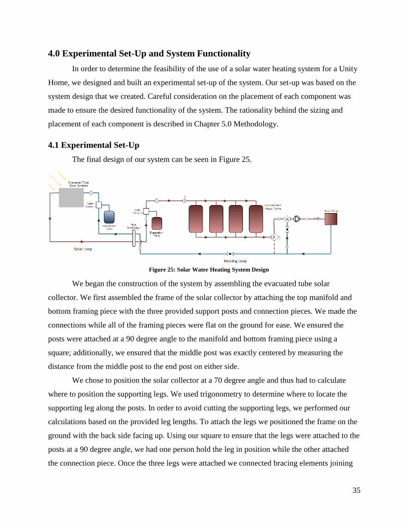
35
4.0 Experimental Set-Up and System Functionality
In order to determine the feasibility of the use of a solar water heating system for a Unity
Home, we designed and built an experimental set-up of the system. Our set-up was based on the
system design that we created. Careful consideration on the placement of each component was
made to ensure the desired functionality of the system. The rationality behind the sizing and
placement of each component is described in Chapter 5.0 Methodology.
4.1 Experimental Set-Up
The final design of our system can be seen in Figure 25.
We began the construction of the system by assembling the evacuated tube solar
collector. We first assembled the frame of the solar collector by attaching the top manifold and
bottom framing piece with the three provided support posts and connection pieces. We made the
connections while all of the framing pieces were flat on the ground for ease. We ensured the
posts were attached at a 90 degree angle to the manifold and bottom framing piece using a
square; additionally, we ensured that the middle post was exactly centered by measuring the
distance from the middle post to the end post on either side.
We chose to position the solar collector at a 70 degree angle and thus had to calculate
where to position the supporting legs. We used trigonometry to determine where to locate the
supporting leg along the posts. In order to avoid cutting the supporting legs, we performed our
calculations based on the provided leg lengths. To attach the legs we positioned the frame on the
ground with the back side facing up. Using our square to ensure that the legs were attached to the
posts at a 90 degree angle, we had one person hold the leg in position while the other attached
the connection piece. Once the three legs were attached we connected bracing elements joining
Figure 25: Solar Water Heating System Design
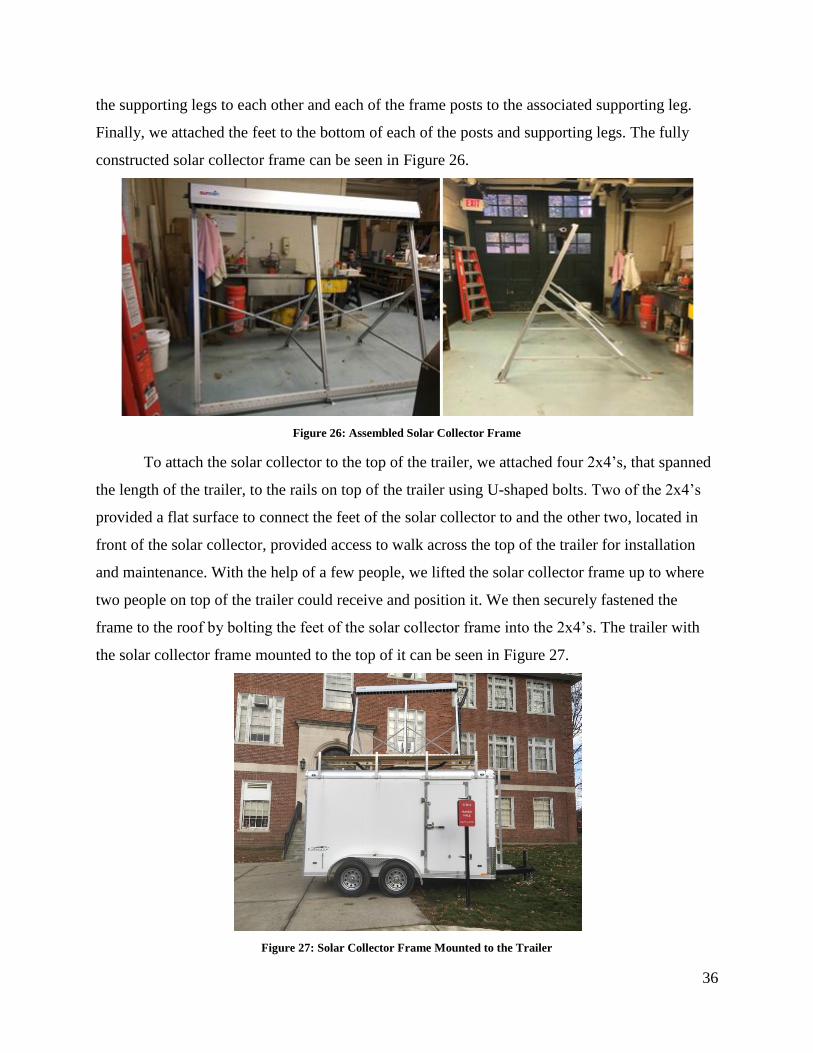
36
the supporting legs to each other and each of the frame posts to the associated supporting leg.
Finally, we attached the feet to the bottom of each of the posts and supporting legs. The fully
constructed solar collector frame can be seen in Figure 26.
Figure 26: Assembled Solar Collector Frame
To attach the solar collector to the top of the trailer, we attached four 2x4’s, that spanned
the length of the trailer, to the rails on top of the trailer using U-shaped bolts. Two of the 2x4’s
provided a flat surface to connect the feet of the solar collector to and the other two, located in
front of the solar collector, provided access to walk across the top of the trailer for installation
and maintenance. With the help of a few people, we lifted the solar collector frame up to where
two people on top of the trailer could receive and position it. We then securely fastened the
frame to the roof by bolting the feet of the solar collector frame into the 2x4’s. The trailer with
the solar collector frame mounted to the top of it can be seen in Figure 27.
Figure 27: Solar Collector Frame Mounted to the Trailer
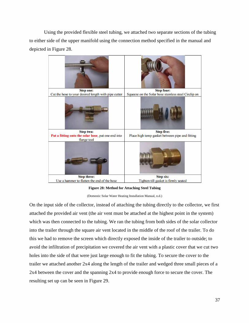
37
Using the provided flexible steel tubing, we attached two separate sections of the tubing
to either side of the upper manifold using the connection method specified in the manual and
depicted in Figure 28.
Figure 28: Method for Attaching Steel Tubing
(Domestic Solar Water Heating Installation Manual, n.d.)
On the input side of the collector, instead of attaching the tubing directly to the collector, we first
attached the provided air vent (the air vent must be attached at the highest point in the system)
which was then connected to the tubing. We ran the tubing from both sides of the solar collector
into the trailer through the square air vent located in the middle of the roof of the trailer. To do
this we had to remove the screen which directly exposed the inside of the trailer to outside; to
avoid the infiltration of precipitation we covered the air vent with a plastic cover that we cut two
holes into the side of that were just large enough to fit the tubing. To secure the cover to the
trailer we attached another 2x4 along the length of the trailer and wedged three small pieces of a
2x4 between the cover and the spanning 2x4 to provide enough force to secure the cover. The
resulting set up can be seen in Figure 29.
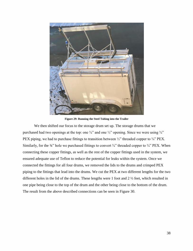
38
Figure 29: Running the Steel Tubing into the Trailer
We then shifted our focus to the storage drum set up. The storage drums that we
purchased had two openings at the top: one ¾” and one ½” opening. Since we were using ¾”
PEX piping, we had to purchase fittings to transition between ½” threaded copper to ¾” PEX.
Similarly, for the ¾” hole we purchased fittings to convert ¾” threaded copper to ¾” PEX. When
connecting these copper fittings, as well as the rest of the copper fittings used in the system, we
ensured adequate use of Teflon to reduce the potential for leaks within the system. Once we
connected the fittings for all four drums, we removed the lids to the drums and crimped PEX
piping to the fittings that lead into the drums. We cut the PEX at two different lengths for the two
different holes in the lid of the drums. These lengths were 1 foot and 2 ½ feet, which resulted in
one pipe being close to the top of the drum and the other being close to the bottom of the drum.
The result from the above described connections can be seen in Figure 30.
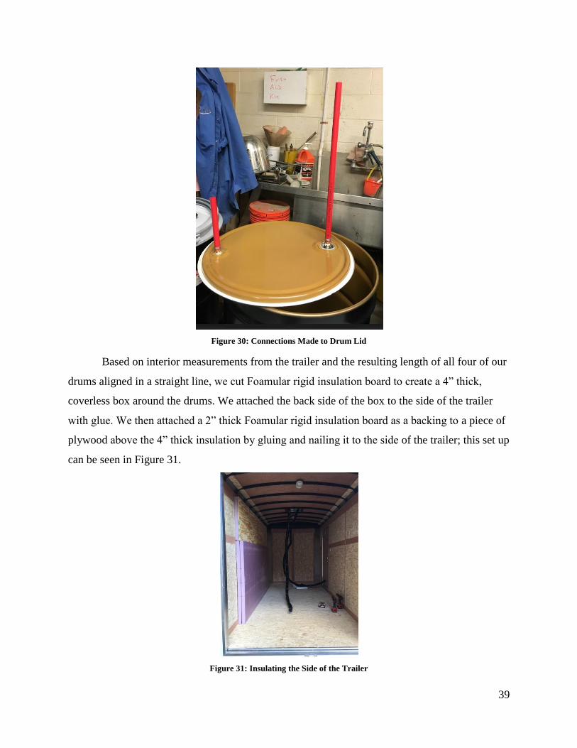
39
Figure 30: Connections Made to Drum Lid
Based on interior measurements from the trailer and the resulting length of all four of our
drums aligned in a straight line, we cut Foamular rigid insulation board to create a 4” thick,
coverless box around the drums. We attached the back side of the box to the side of the trailer
with glue. We then attached a 2” thick Foamular rigid insulation board as a backing to a piece of
plywood above the 4” thick insulation by gluing and nailing it to the side of the trailer; this set up
can be seen in Figure 31.
Figure 31: Insulating the Side of the Trailer

40
We then attached the two Wilo Star pumps at opposite ends of the plywood as well as the
expansion tank for the solar loop which was placed next to the pump to be used for the solar
loop. We also attached the heat exchanger to the plywood placing it in the middle between the
two pumps. When attaching the heat exchanger we had to first attach a piece of wood to the
plywood to ensure that both the PEX and the flexible steel tubing had enough room to be
properly attached to the heat exchanger. We were then able to finish connecting all of the
flexible steel tubing for the solar loop. We connected the flexible tubing that was fed into the
trailer from the output of the solar collector to the “in” port on the heat exchanger. The tubing
that was fed into the trailer from the input of the solar collector was connected to the output (top)
of the Wilo Star pump for the solar loop. We then cut flexible steel tubing to connect the input
(bottom) of the Wilo Star pump for the solar loop to the “out” port on the heat exchanger and to
connect the Wilo Star pump to the expansion tank. All of the connections were made using the
method depicted in Figure 28.
Once the solar loop was complete we turned our attention back to setting up the drums.
We used the bottom box piece of insulation we had cut earlier as a platform to continue with our
set up of the storage drums so that we could set this section of the system up indoors to avoid the
cold weather. We aligned our drums on top of the insulation and began cutting pieces of PEX to
connect the drums together, where the set of holes on top of the drums that had the shorter length
of PEX inside the drums beneath them would be connected in a line and the other holes with the
longer length of PEX inside the drums beneath them would be connected in a separate line, this
set up can be seen in Figure 32.

41
Figure 32: Line Piping Connecting Drums
Additionally, since one length of piping will serve as the inlet and the other will serve as the
outlet, one line will end in one of the end drums and the other line will end in the opposing end
drum. We then crimped together all of the PEX to the fittings except for the final connection to
the drums. Once we successfully attached the tanks along each set of holes and crimped together
the PEX lines, we outlined the base of the drums on the insulation with a marker and labeled
each drum with a number, both on the drum and next to the associated outline on the insulation.
We then removed the PEX lines from the drums and the drums from the insulation and brought
each of the components into the trailer. We reassembled the drums and crimped the PEX lines
onto the drums. Once the drums positions were finalized, we attached the two side pieces of the
insulation. Because on either end of the drums the piping extends to connect to other parts of the
system, we cut holes in the insulation to allow the PEX to pass through. We then glued and
nailed the side pieces of insulation to the back and bottom pieces already in place.
In order to connect the rest of the heating loop, we needed to determine where to position
the heat pump. We decided to place the heat pump on the wall of the trailer opposing the tanks to
be able to allow full access to the trailer and provide more wall space to build the mixing loop.
We decided to build a stand for the heat pump and march pump in order to be able to position the
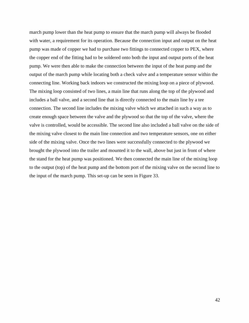
42
march pump lower than the heat pump to ensure that the march pump will always be flooded
with water, a requirement for its operation. Because the connection input and output on the heat
pump was made of copper we had to purchase two fittings to connected copper to PEX, where
the copper end of the fitting had to be soldered onto both the input and output ports of the heat
pump. We were then able to make the connection between the input of the heat pump and the
output of the march pump while locating both a check valve and a temperature sensor within the
connecting line. Working back indoors we constructed the mixing loop on a piece of plywood.
The mixing loop consisted of two lines, a main line that runs along the top of the plywood and
includes a ball valve, and a second line that is directly connected to the main line by a tee
connection. The second line includes the mixing valve which we attached in such a way as to
create enough space between the valve and the plywood so that the top of the valve, where the
valve is controlled, would be accessible. The second line also included a ball valve on the side of
the mixing valve closest to the main line connection and two temperature sensors, one on either
side of the mixing valve. Once the two lines were successfully connected to the plywood we
brought the plywood into the trailer and mounted it to the wall, above but just in front of where
the stand for the heat pump was positioned. We then connected the main line of the mixing loop
to the output (top) of the heat pump and the bottom port of the mixing valve on the second line to
the input of the march pump. This set-up can be seen in Figure 33.
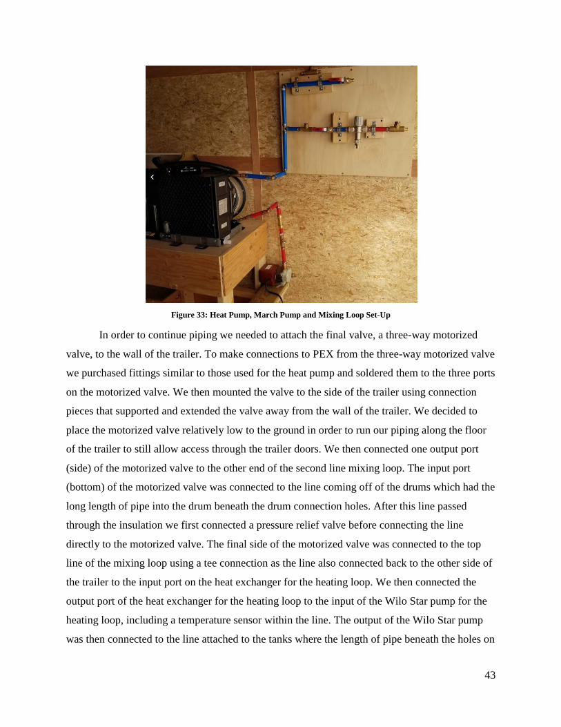
43
Figure 33: Heat Pump, March Pump and Mixing Loop Set-Up
In order to continue piping we needed to attach the final valve, a three-way motorized
valve, to the wall of the trailer. To make connections to PEX from the three-way motorized valve
we purchased fittings similar to those used for the heat pump and soldered them to the three ports
on the motorized valve. We then mounted the valve to the side of the trailer using connection
pieces that supported and extended the valve away from the wall of the trailer. We decided to
place the motorized valve relatively low to the ground in order to run our piping along the floor
of the trailer to still allow access through the trailer doors. We then connected one output port
(side) of the motorized valve to the other end of the second line mixing loop. The input port
(bottom) of the motorized valve was connected to the line coming off of the drums which had the
long length of pipe into the drum beneath the drum connection holes. After this line passed
through the insulation we first connected a pressure relief valve before connecting the line
directly to the motorized valve. The final side of the motorized valve was connected to the top
line of the mixing loop using a tee connection as the line also connected back to the other side of
the trailer to the input port on the heat exchanger for the heating loop. We then connected the
output port of the heat exchanger for the heating loop to the input of the Wilo Star pump for the
heating loop, including a temperature sensor within the line. The output of the Wilo Star pump
was then connected to the line attached to the tanks where the length of pipe beneath the holes on
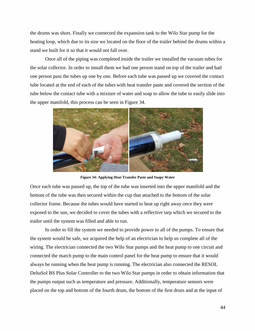
44
the drums was short. Finally we connected the expansion tank to the Wilo Star pump for the
heating loop, which due to its size we located on the floor of the trailer behind the drums within a
stand we built for it so that it would not fall over.
Once all of the piping was completed inside the trailer we installed the vacuum tubes for
the solar collector. In order to install them we had one person stand on top of the trailer and had
one person pass the tubes up one by one. Before each tube was passed up we covered the contact
tube located at the end of each of the tubes with heat transfer paste and covered the section of the
tube below the contact tube with a mixture of water and soap to allow the tube to easily slide into
the upper manifold, this process can be seen in Figure 34.
Figure 34: Applying Heat Transfer Paste and Soapy Water
Once each tube was passed up, the top of the tube was inserted into the upper manifold and the
bottom of the tube was then secured within the cup that attached to the bottom of the solar
collector frame. Because the tubes would have started to heat up right away once they were
exposed to the sun, we decided to cover the tubes with a reflective tarp which we secured to the
trailer until the system was filled and able to run.
In order to fill the system we needed to provide power to all of the pumps. To ensure that
the system would be safe, we acquired the help of an electrician to help us complete all of the
wiring. The electrician connected the two Wilo Star pumps and the heat pump to one circuit and
connected the march pump to the main control panel for the heat pump to ensure that it would
always be running when the heat pump is running. The electrician also connected the RESOL
DeltaSol BS Plus Solar Controller to the two Wilo Star pumps in order to obtain information that
the pumps output such as temperature and pressure. Additionally, temperature sensors were
placed on the top and bottom of the fourth drum, the bottom of the first drum and at the input of
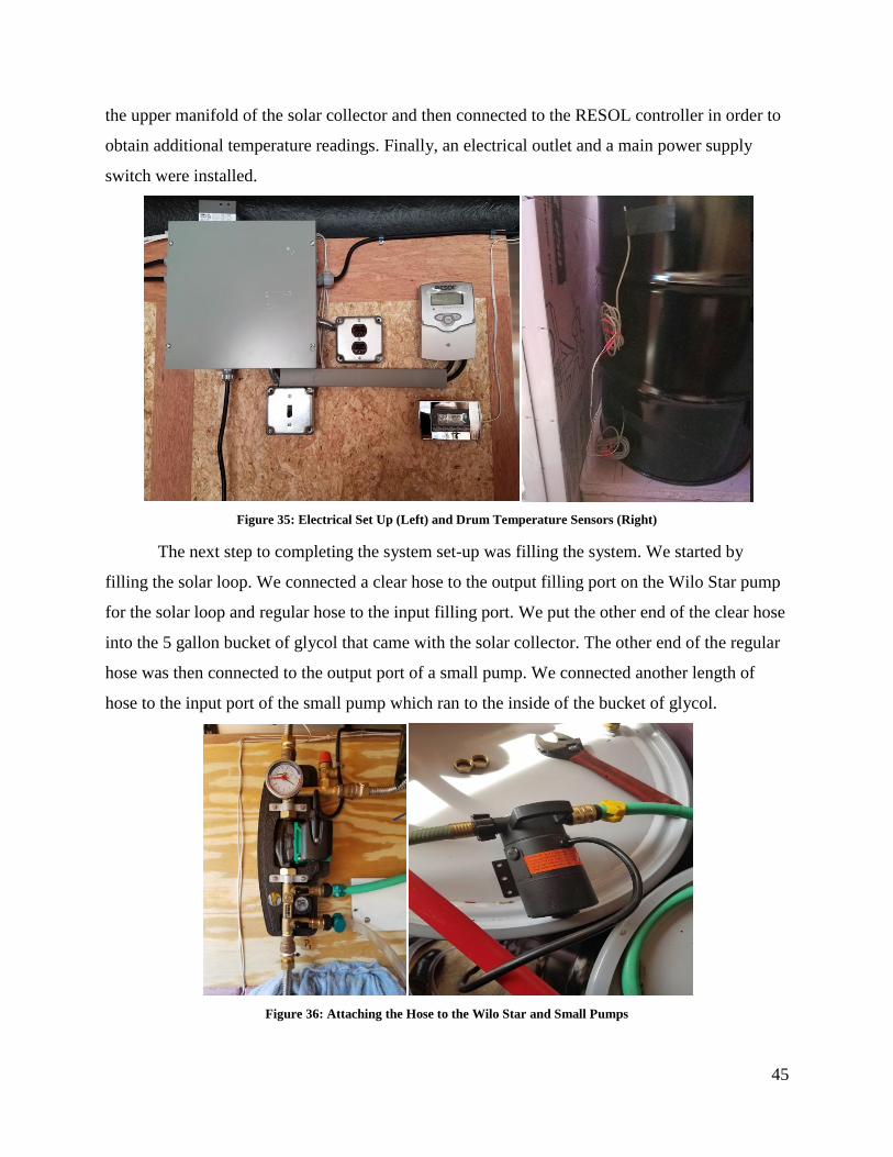
45
the upper manifold of the solar collector and then connected to the RESOL controller in order to
obtain additional temperature readings. Finally, an electrical outlet and a main power supply
switch were installed.
Figure 35: Electrical Set Up (Left) and Drum Temperature Sensors (Right)
The next step to completing the system set-up was filling the system. We started by
filling the solar loop. We connected a clear hose to the output filling port on the Wilo Star pump
for the solar loop and regular hose to the input filling port. We put the other end of the clear hose
into the 5 gallon bucket of glycol that came with the solar collector. The other end of the regular
hose was then connected to the output port of a small pump. We connected another length of
hose to the input port of the small pump which ran to the inside of the bucket of glycol.
Figure 36: Attaching the Hose to the Wilo Star and Small Pumps
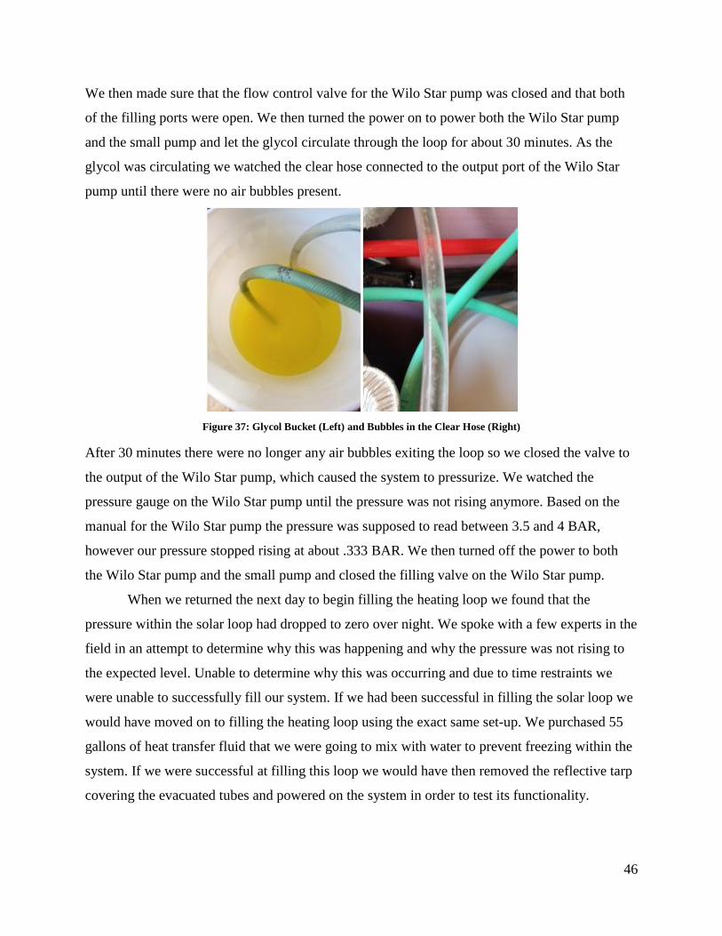
46
We then made sure that the flow control valve for the Wilo Star pump was closed and that both
of the filling ports were open. We then turned the power on to power both the Wilo Star pump
and the small pump and let the glycol circulate through the loop for about 30 minutes. As the
glycol was circulating we watched the clear hose connected to the output port of the Wilo Star
pump until there were no air bubbles present.
Figure 37: Glycol Bucket (Left) and Bubbles in the Clear Hose (Right)
After 30 minutes there were no longer any air bubbles exiting the loop so we closed the valve to
the output of the Wilo Star pump, which caused the system to pressurize. We watched the
pressure gauge on the Wilo Star pump until the pressure was not rising anymore. Based on the
manual for the Wilo Star pump the pressure was supposed to read between 3.5 and 4 BAR,
however our pressure stopped rising at about .333 BAR. We then turned off the power to both
the Wilo Star pump and the small pump and closed the filling valve on the Wilo Star pump.
When we returned the next day to begin filling the heating loop we found that the
pressure within the solar loop had dropped to zero over night. We spoke with a few experts in the
field in an attempt to determine why this was happening and why the pressure was not rising to
the expected level. Unable to determine why this was occurring and due to time restraints we
were unable to successfully fill our system. If we had been successful in filling the solar loop we
would have moved on to filling the heating loop using the exact same set-up. We purchased 55
gallons of heat transfer fluid that we were going to mix with water to prevent freezing within the
system. If we were successful at filling this loop we would have then removed the reflective tarp
covering the evacuated tubes and powered on the system in order to test its functionality.
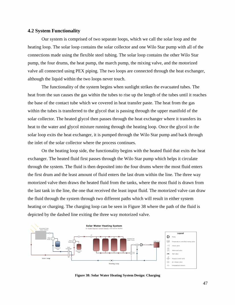
47
4.2 System Functionality
Our system is comprised of two separate loops, which we call the solar loop and the
heating loop. The solar loop contains the solar collector and one Wilo Star pump with all of the
connections made using the flexible steel tubing. The solar loop contains the other Wilo Star
pump, the four drums, the heat pump, the march pump, the mixing valve, and the motorized
valve all connected using PEX piping. The two loops are connected through the heat exchanger,
although the liquid within the two loops never touch.
The functionality of the system begins when sunlight strikes the evacuated tubes. The
heat from the sun causes the gas within the tubes to rise up the length of the tubes until it reaches
the base of the contact tube which we covered in heat transfer paste. The heat from the gas
within the tubes is transferred to the glycol that is passing through the upper manifold of the
solar collector. The heated glycol then passes through the heat exchanger where it transfers its
heat to the water and glycol mixture running through the heating loop. Once the glycol in the
solar loop exits the heat exchanger, it is pumped through the Wilo Star pump and back through
the inlet of the solar collector where the process continues.
On the heating loop side, the functionality begins with the heated fluid that exits the heat
exchanger. The heated fluid first passes through the Wilo Star pump which helps it circulate
through the system. The fluid is then deposited into the four drums where the most fluid enters
the first drum and the least amount of fluid enters the last drum within the line. The three way
motorized valve then draws the heated fluid from the tanks, where the most fluid is drawn from
the last tank in the line, the one that received the least input fluid. The motorized valve can draw
the fluid through the system through two different paths which will result in either system
heating or charging. The charging loop can be seen in Figure 38 where the path of the fluid is
depicted by the dashed line exiting the three way motorized valve.
Figure 38: Solar Water Heating System Design: Charging

48
In this configuration, the motorized valve is set to bypass the heat pump and continue to circulate
the fluid continuously through the heat exchanger in order to maintain a hot water temperature
within the tanks. Alternatively, the system can be in heating mode, depicted in Figure 39 where
the path of the fluid is shown as a dotted line exiting the motorized valve.
Figure 39: Solar Water Heating System Design: Heating
In this configuration, the motorized valve is set to only allow the fluid to pass through the heat
pump. Upon exiting the motorized valve the fluid travels through the mixing valve where it is
mixed with the cold water exiting the heat pump in order to obtain an optimal temperature for
entering the heat pump. The fluid that exits the mixing valve first enters through the march pump
and the check valve, to ensure that no back flow occurs, before entering the heat pump. When the
fluid passes through the heat pump the heat from the fluid is transferred into the air that the heat
pump blows into the air. Then now cold fluid exits the heat pump, where some of it travels
through the mixing loop to mix with the entering hot water and the rest of it travels back to the
heat exchanger where it is heated up and the cycle continues. Ideally, the three way motorized
valve would be controlled by the heat pump where when the heat pump is triggered to turn on
due to the space temperature, the motorized valve would switch to the heating phase and vice
versa. Although we were not able to configure this function, we designed the system with this
intention.
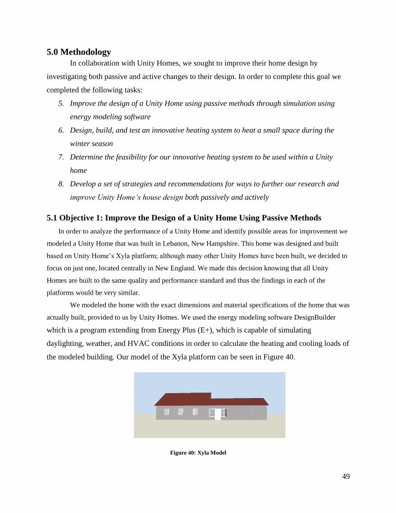
49
5.0 Methodology
In collaboration with Unity Homes, we sought to improve their home design by
investigating both passive and active changes to their design. In order to complete this goal we
completed the following tasks:
5. Improve the design of a Unity Home using passive methods through simulation using
energy modeling software
6. Design, build, and test an innovative heating system to heat a small space during the
winter season
7. Determine the feasibility for our innovative heating system to be used within a Unity
home
8. Develop a set of strategies and recommendations for ways to further our research and
improve Unity Home’s house design both passively and actively
5.1 Objective 1: Improve the Design of a Unity Home Using Passive Methods
In order to analyze the performance of a Unity Home and identify possible areas for improvement we
modeled a Unity Home that was built in Lebanon, New Hampshire. This home was designed and built
based on Unity Home’s Xyla platform; although many other Unity Homes have been built, we decided to
focus on just one, located centrally in New England. We made this decision knowing that all Unity
Homes are built to the same quality and performance standard and thus the findings in each of the
platforms would be very similar.
We modeled the home with the exact dimensions and material specifications of the home that was
actually built, provided to us by Unity Homes. We used the energy modeling software DesignBuilder
which is a program extending from Energy Plus (E+), which is capable of simulating
daylighting, weather, and HVAC conditions in order to calculate the heating and cooling loads of
the modeled building. Our model of the Xyla platform can be seen in Figure 40.
Figure 40: Xyla Model
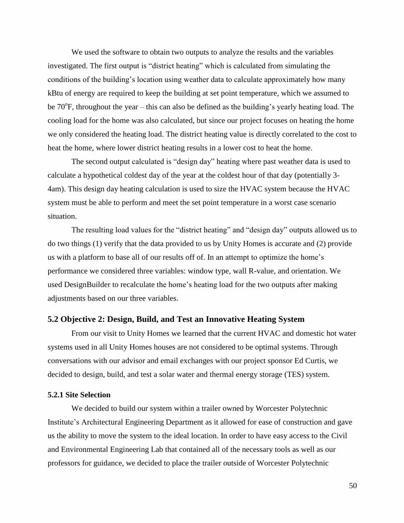
50
We used the software to obtain two outputs to analyze the results and the variables
investigated. The first output is “district heating” which is calculated from simulating the
conditions of the building’s location using weather data to calculate approximately how many
kBtu of energy are required to keep the building at set point temperature, which we assumed to
be 70oF, throughout the year – this can also be defined as the building’s yearly heating load. The
cooling load for the home was also calculated, but since our project focuses on heating the home
we only considered the heating load. The district heating value is directly correlated to the cost to
heat the home, where lower district heating results in a lower cost to heat the home.
The second output calculated is “design day” heating where past weather data is used to
calculate a hypothetical coldest day of the year at the coldest hour of that day (potentially 3-
4am). This design day heating calculation is used to size the HVAC system because the HVAC
system must be able to perform and meet the set point temperature in a worst case scenario
situation.
The resulting load values for the “district heating” and “design day” outputs allowed us to
do two things (1) verify that the data provided to us by Unity Homes is accurate and (2) provide
us with a platform to base all of our results off of. In an attempt to optimize the home’s
performance we considered three variables: window type, wall R-value, and orientation. We
used DesignBuilder to recalculate the home’s heating load for the two outputs after making
adjustments based on our three variables.
5.2 Objective 2: Design, Build, and Test an Innovative Heating System
From our visit to Unity Homes we learned that the current HVAC and domestic hot water
systems used in all Unity Homes houses are not considered to be optimal systems. Through
conversations with our advisor and email exchanges with our project sponsor Ed Curtis, we
decided to design, build, and test a solar water and thermal energy storage (TES) system.
5.2.1 Site Selection
We decided to build our system within a trailer owned by Worcester Polytechnic
Institute’s Architectural Engineering Department as it allowed for ease of construction and gave
us the ability to move the system to the ideal location. In order to have easy access to the Civil
and Environmental Engineering Lab that contained all of the necessary tools as well as our
professors for guidance, we decided to place the trailer outside of Worcester Polytechnic
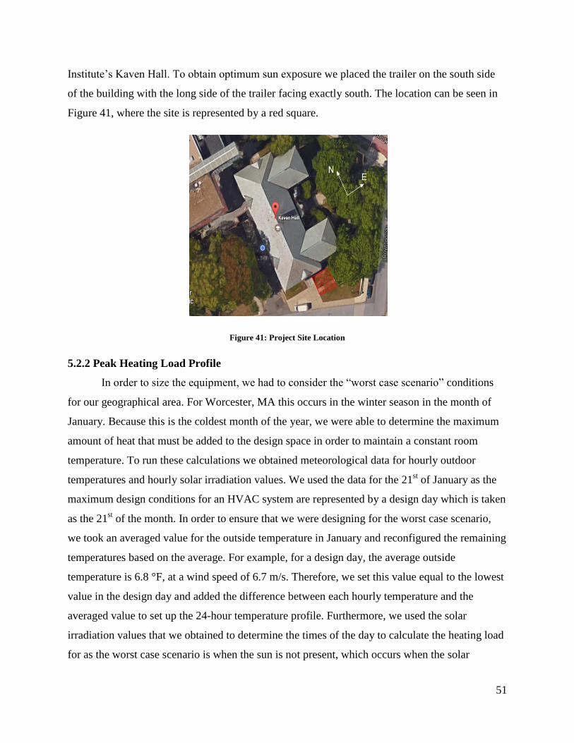
51
Institute’s Kaven Hall. To obtain optimum sun exposure we placed the trailer on the south side
of the building with the long side of the trailer facing exactly south. The location can be seen in
Figure 41, where the site is represented by a red square.
Figure 41: Project Site Location
5.2.2 Peak Heating Load Profile
In order to size the equipment, we had to consider the “worst case scenario” conditions
for our geographical area. For Worcester, MA this occurs in the winter season in the month of
January. Because this is the coldest month of the year, we were able to determine the maximum
amount of heat that must be added to the design space in order to maintain a constant room
temperature. To run these calculations we obtained meteorological data for hourly outdoor
temperatures and hourly solar irradiation values. We used the data for the 21st of January as the
maximum design conditions for an HVAC system are represented by a design day which is taken
as the 21st of the month. In order to ensure that we were designing for the worst case scenario,
we took an averaged value for the outside temperature in January and reconfigured the remaining
temperatures based on the average. For example, for a design day, the average outside
temperature is 6.8 °F, at a wind speed of 6.7 m/s. Therefore, we set this value equal to the lowest
value in the design day and added the difference between each hourly temperature and the
averaged value to set up the 24-hour temperature profile. Furthermore, we used the solar
irradiation values that we obtained to determine the times of the day to calculate the heating load
for as the worst case scenario is when the sun is not present, which occurs when the solar
52
irradiance is equal to 0. Because we intended on testing the system from December through
February, we decided to also look at the solar irradiation values for the months of December and
February to ensure that we would be obtaining accurate values for our load profile.
In order to calculate the peak heating load we performed manual calculations which we
then checked with the results from a simulated model in DesignBuilder. The processes that make
up a heat balance model within a zone are split into four different categories: (1) Outside face
heat balance, (2) Wall conduction process, (3) Inside face heat balance, and (4) Air heat balance.
This relationship can be seen in Figure 42.
Figure 42: Heat Balance Flow Chart
(Fallahi, 2016)
Considering the following information, the heat balance model for the trailer will exhibit
conductive, convective, radiation, and infiltration losses/gains. As noted before, the trailer will
not exhibit solar gains due to our worst case scenario criteria. To calculate the interior and
exterior losses and/or gains through the wall construction we named each surface, as seen in
Figure 43.
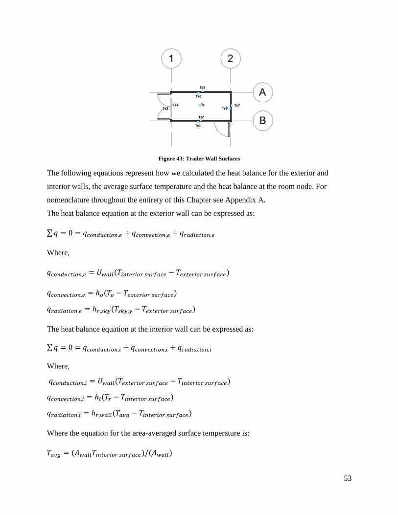
53
Figure 43: Trailer Wall Surfaces
The following equations represent how we calculated the heat balance for the exterior and
interior walls, the average surface temperature and the heat balance at the room node. For
nomenclature throughout the entirety of this Chapter see Appendix A.
The heat balance equation at the exterior wall can be expressed as:
Where,
The heat balance equation at the interior wall can be expressed as:
Where,
Where the equation for the area-averaged surface temperature is:
54
Lastly, the heat balance equation at the room node can be expressed as:
Where,
(Fallahi, 2016).
These equations were used to calculate each wall’s interior and exterior surface temperature, the
average room temperature and qHVAC which is the heat needed to maintain the design space at the
desired set point temperature; this list of equations can be seen in Appendix B. In order to use the
equations we made the following assumptions:
Design indoor temperature is 68 °F,
Infiltration rate is 0.6 ACH,
Assume there are no internal gains from any mechanical sources, lights, and people,
Since the walls and doors are made of the same materials, assume each wall of the trailer
is continuous,
In efforts to sufficiently insulate the trailer, we are closing the hatch located on the roof;
thus we will assume that the roof is continuous, and for ease of calculation, flat,
Ignore exterior LW radiation with the surroundings (refer to Figure 42),
Ignore thermal bridging effects, and
Ignore latent loads.
To solve the equations, we created a matrix in excel to solve for each variable for each hourly
temperature that was included in our peak heat load profile.
In addition to manual calculations, we simulated a model of the trailer in the energy
modeling software DesignBuilder. We created a model of the trailer in DesignBuilder, seen in
Figure 44, and indicated the wall materials, site location, heating set point temperatures,
infiltration rate, and zone type. We also made the same assumptions as we did in our manual
calculations when setting up the energy model. The software used weather data for Worcester,
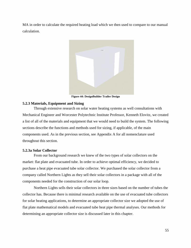
55
MA in order to calculate the required heating load which we then used to compare to our manual
calculation.
Figure 44: DesignBuilder Trailer Design
5.2.3 Materials, Equipment and Sizing
Through extensive research on solar water heating systems as well consultations with
Mechanical Engineer and Worcester Polytechnic Institute Professor, Kenneth Elovitz, we created
a list of all of the materials and equipment that we would need to build the system. The following
sections describe the functions and methods used for sizing, if applicable, of the main
components used. As in the previous section, see Appendix A for all nomenclature used
throughout this section.
5.2.3a Solar Collector
From our background research we knew of the two types of solar collectors on the
market: flat plate and evacuated tube. In order to achieve optimal efficiency, we decided to
purchase a heat pipe evacuated tube solar collector. We purchased the solar collector from a
company called Northern Lights as they sell their solar collectors in a package with all of the
components needed for the construction of our solar loop.
Northern Lights sells their solar collectors in three sizes based on the number of tubes the
collector has. Because there is minimal research available on the use of evacuated tube collectors
for solar heating applications, to determine an appropriate collector size we adopted the use of
flat plate mathematical models and evacuated tube heat pipe thermal analyses. Our methods for
determining an appropriate collector size is discussed later in this chapter.

56
5.2.3b Heat Pump
For our application we purchased a marine heat pump which is a water to air heat pump.
This pump is what allowed us to convert the heat stored in the water in our drums into the air to
heat the space. This type of heat pump is normally used on boats, however its fundamental
operations correspond to the principles used in our system.
In order to size the heat pump we used our results obtained from conducting our heating
load profile. The manual calculations and energy modeling that we completed allowed us to
determine the amount of heat per hour that is needed to heat the trailer. Instead of purchasing the
heat pump based on our sizing calculation, we instead decided to purchase a heat pump that had
the potential to heat a Unity Home. The Xyla house that we modeled in DesignBuilder requires
14.434 kBTU/hr based on information provided to us by Unity Homes and our energy simulation
conducted for the home completed in DesignBuilder for validation. Thus, we decided to
purchase a 16 kBTU/hr heat pump so that when we integrate our system into the Xyla model we
would be able to see if our system could successfully heat the home.
5.2.3c Storage Drums
In order to store the hot fluid generated from the solar collector until the heat pump was
activated to heat the space, we needed to purchase storage drums. To protect our system from
rust and corrosion we decided to use stainless steel drums. Although we considered using one
large water storage tank, we ultimately decided to use a series of smaller drums in order to create
a gradual temperature difference between the drums. Additionally, smaller drums would be
easier to maneuver and when considering a price per gallon we generally found the smaller
drums to be cheaper.
Because we were unable to find any research similar to our system, we first sized our
drums based on a basic heat transfer analysis. In order to verify our initial sizing calculations to
ensure that the determined volume of fluid would be able to store the necessary heat, we
completed an analysis based on a domestic hot water system set up which will be discussed later
in this chapter.
5.2.3d Circulating Pumps
Our system design included three pumps in addition to the heat pump: the two Wilo Star
pumps, one for each loop, and the march pump. The purpose of these three pumps was to provide
circulation throughout the system, as they continuously draw fluid through them.
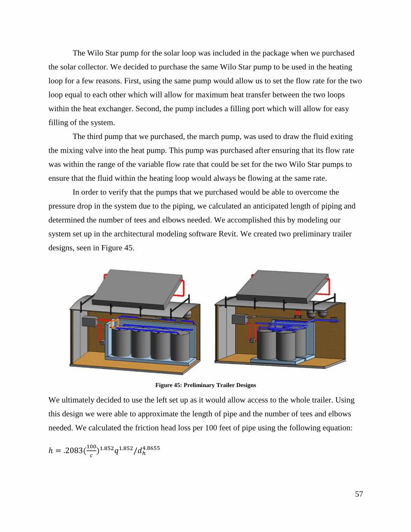
57
The Wilo Star pump for the solar loop was included in the package when we purchased
the solar collector. We decided to purchase the same Wilo Star pump to be used in the heating
loop for a few reasons. First, using the same pump would allow us to set the flow rate for the two
loop equal to each other which will allow for maximum heat transfer between the two loops
within the heat exchanger. Second, the pump includes a filling port which will allow for easy
filling of the system.
The third pump that we purchased, the march pump, was used to draw the fluid exiting
the mixing valve into the heat pump. This pump was purchased after ensuring that its flow rate
was within the range of the variable flow rate that could be set for the two Wilo Star pumps to
ensure that the fluid within the heating loop would always be flowing at the same rate.
In order to verify that the pumps that we purchased would be able to overcome the
pressure drop in the system due to the piping, we calculated an anticipated length of piping and
determined the number of tees and elbows needed. We accomplished this by modeling our
system set up in the architectural modeling software Revit. We created two preliminary trailer
designs, seen in Figure 45.
Figure 45: Preliminary Trailer Designs
We ultimately decided to use the left set up as it would allow access to the whole trailer. Using
this design we were able to approximate the length of pipe and the number of tees and elbows
needed. We calculated the friction head loss per 100 feet of pipe using the following equation:
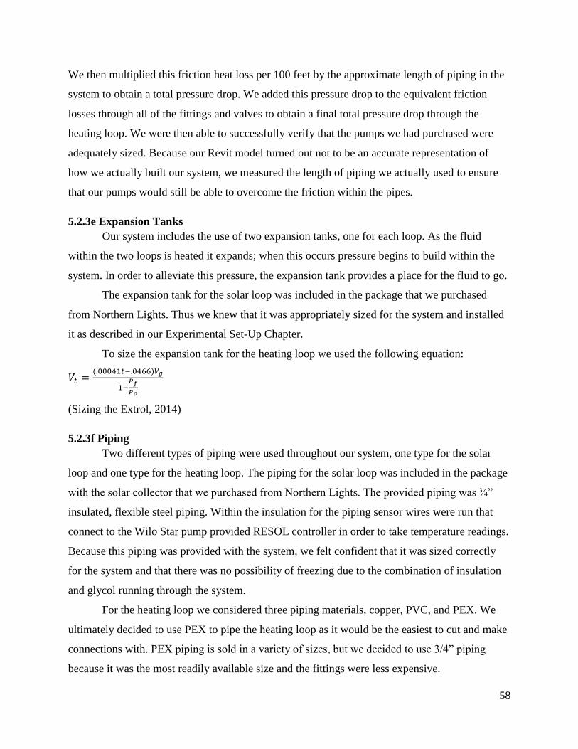
58
We then multiplied this friction heat loss per 100 feet by the approximate length of piping in the
system to obtain a total pressure drop. We added this pressure drop to the equivalent friction
losses through all of the fittings and valves to obtain a final total pressure drop through the
heating loop. We were then able to successfully verify that the pumps we had purchased were
adequately sized. Because our Revit model turned out not to be an accurate representation of
how we actually built our system, we measured the length of piping we actually used to ensure
that our pumps would still be able to overcome the friction within the pipes.
5.2.3e Expansion Tanks
Our system includes the use of two expansion tanks, one for each loop. As the fluid
within the two loops is heated it expands; when this occurs pressure begins to build within the
system. In order to alleviate this pressure, the expansion tank provides a place for the fluid to go.
The expansion tank for the solar loop was included in the package that we purchased
from Northern Lights. Thus we knew that it was appropriately sized for the system and installed
it as described in our Experimental Set-Up Chapter.
To size the expansion tank for the heating loop we used the following equation:
(Sizing the Extrol, 2014)
5.2.3f Piping
Two different types of piping were used throughout our system, one type for the solar
loop and one type for the heating loop. The piping for the solar loop was included in the package
with the solar collector that we purchased from Northern Lights. The provided piping was ¾”
insulated, flexible steel piping. Within the insulation for the piping sensor wires were run that
connect to the Wilo Star pump provided RESOL controller in order to take temperature readings.
Because this piping was provided with the system, we felt confident that it was sized correctly
for the system and that there was no possibility of freezing due to the combination of insulation
and glycol running through the system.
For the heating loop we considered three piping materials, copper, PVC, and PEX. We
ultimately decided to use PEX to pipe the heating loop as it would be the easiest to cut and make
connections with. PEX piping is sold in a variety of sizes, but we decided to use 3/4” piping
because it was the most readily available size and the fittings were less expensive.
59
5.2.3g Valves
Our system includes the use of five different types of valves. The type of valve that was
used in both loops of our system was an air relief valve. As trapped air will tend to accumulate at
the highest point within the system, the air relief valve was installed at the highest point for both
loops within our system. Additionally, they were installed on the outflow side of the Wilo Star
pumps in order to alleviate any generated air upon pump start-up.
Within our heating loop we also incorporated a pressure relief valve. As the expansion
tank allows for fluid expansion as the pressure builds, the pressure relief valve is a safety feature
that is activated in the event of too much pressure build up. The pressure relief valve was set to
go off at a system pressure of 30 psi to prevent damage to our system components.
Our heating loop also includes two ball valves located within the mixing loop of our
system. Both of these valves allow us to manually control the flow within our system in the event
of a component failure.
We also included one check valve in our heating loop placed between the march pump
and the heat pump. The check valve allows flow in one direction thus eliminating the potential
for backflow from the heat pump.
The final valve used within our system is the three-way motorized valve. This valve, like
the check valve, will only allow flow in a certain direction within our system. It will either allow
the fluid to flow from the drums to the heat pump, preventing fluid exiting the heat pump from
entering the stream, or bypass the heat pump and flow back through the heat exchanger.
5.2.3h Sensors
In order to acquire temperature readings to gauge how well our system is functioning, we
placed temperature sensors throughout our system. The flexible steel tubing provided with the
solar collector contained temperature sensing wires within the insulation of the tubing. These
sensors connect to the input and output ports on both the Wilo Star pump and upper manifold of
the solar collector. The RESOL controller that attaches to the Wilo Star pump then records these
temperature readings based on set time intervals.
For the heating loop we purchased temperature sensors to be placed along the piping
throughout the loop. We used five of these temperature sensors placing them in the following
locations:
1. The output of the heat exchanger
60
2. The input of the mixing valve coming from the storage drums
3. The input of the mixing valve coming from the output of the heat pump
4. The output of the mixing valve
5. The input of the heat exchanger
In order to obtain temperature readings from the fluid within the drums, we attached temperature
sensors to the exterior of the drums. Because we were interested in the temperature difference
between the top and bottom of the drums as well as between the first and last drum within the
series connection, we placed these temperature sensors in the following locations:
1. The bottom of the first drum
2. The bottom of the fourth drum
3. The top of the fourth drum
To have access to these temperature readings we intended to connect all of the sensors to a
controller, much like the RESOL controller. However, due to time constraints and lack of
electrical knowledge we were unable to connect the sensors.
5.2.3i Insulation
Because we built our system within a poorly insulated trailer and it is intended to be used
throughout the winter season, we decided to install insulation to decrease the potential for
freezing within the pipes and reduce the heat loss from the drums. We purchased 4’x8’x2” sheets
of Foamular rigid insulation board to insulate our system. Although we had other options, rigid
board insulation would be the easiest to work with and it was the most cost effective choice
based on the provided R-value. We installed a single layer of the insulation board behind the
plywood that we mounted our two Wilo Star pumps and heat exchanger on in order to prevent
damage to the pumps. To insulate the drums, we decided to glue two sheets of the rigid board
insulation together to provide a greater R-value, as we were anticipating there to be a lot of heat
loss off the drums. We cut the insulation board to create a box around the drums. Because we
were not able to successfully fill our system, we did not install the front side of cover to the box;
however, we were planning on creating a trapezoidal cover, as opposed to a flat cover, in order to
enclose the two Wilo Star pumps and the heat exchanger to provide increased protection from
freezing.

61
5.2.3j Fluids
As an additional measure to prevent freezing within the pipes, both our solar and heating
loops were intended to be filled with a glycol and water mixture. With the solar collector that we
purchased came a five gallon bucket of pre-mixed propylene glycol. The manual for the solar
collector included a table relating the ratio of glycol in the mixture to respective operable
temperature ranges, seen in Figure 46.
Figure 46: Freezing and Boiling Points of Propylene Glycol Solution
Because the system came with a pre-mixed 50/50 glycol to water mixture and the temperature
range presented in the table was fitting to New England, we decided not to further mix the
solution.
Because we also wanted to use a glycol mixture within our heating loop, we calculated
the volume of fluid within the loop and used the same table to choose an appropriate ratio. We
calculated the volume of the heating loop, which included the volume of the drums plus the
volume of all of the piping.
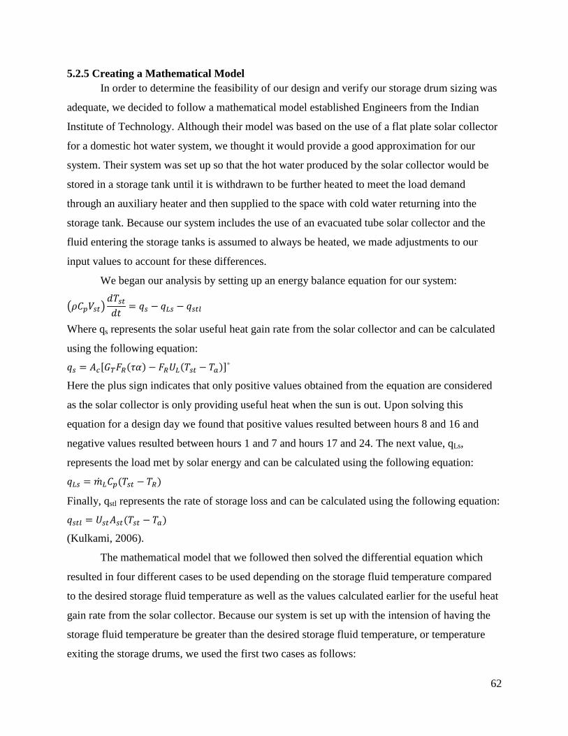
62
5.2.5 Creating a Mathematical Model
In order to determine the feasibility of our design and verify our storage drum sizing was
adequate, we decided to follow a mathematical model established Engineers from the Indian
Institute of Technology. Although their model was based on the use of a flat plate solar collector
for a domestic hot water system, we thought it would provide a good approximation for our
system. Their system was set up so that the hot water produced by the solar collector would be
stored in a storage tank until it is withdrawn to be further heated to meet the load demand
through an auxiliary heater and then supplied to the space with cold water returning into the
storage tank. Because our system includes the use of an evacuated tube solar collector and the
fluid entering the storage tanks is assumed to always be heated, we made adjustments to our
input values to account for these differences.
We began our analysis by setting up an energy balance equation for our system:
Where qs represents the solar useful heat gain rate from the solar collector and can be calculated
using the following equation:
+
Here the plus sign indicates that only positive values obtained from the equation are considered
as the solar collector is only providing useful heat when the sun is out. Upon solving this
equation for a design day we found that positive values resulted between hours 8 and 16 and
negative values resulted between hours 1 and 7 and hours 17 and 24. The next value, qLs,
represents the load met by solar energy and can be calculated using the following equation:
Finally, qstl represents the rate of storage loss and can be calculated using the following equation:
(Kulkami, 2006).
The mathematical model that we followed then solved the differential equation which
resulted in four different cases to be used depending on the storage fluid temperature compared
to the desired storage fluid temperature as well as the values calculated earlier for the useful heat
gain rate from the solar collector. Because our system is set up with the intension of having the
storage fluid temperature be greater than the desired storage fluid temperature, or temperature
exiting the storage drums, we used the first two cases as follows:
63
Case I ( and :
Case II ( :
(Kulkami, 2006).
Based on our results from calculating the useful heat gain rate from the solar collector we
determined that Case I should be used for hours 8 through 16 and Case II should be used for
hours 1 through 7 and hours 17 through 24. Based on weather data from Energy Plus, we solved
for the final storage fluid temperature, or the storage fluid temperature at the end of the day, for
each hour of the day for the first 24 days in the month of January and obtained the following
graph:
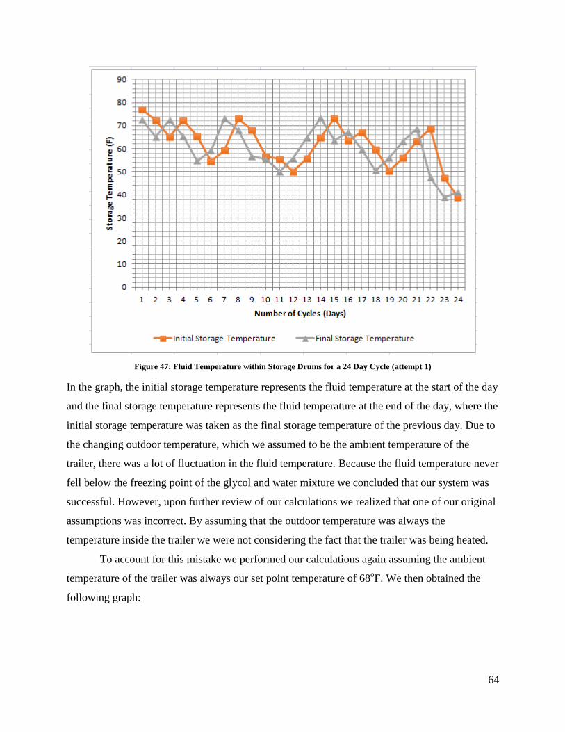
64
Figure 47: Fluid Temperature within Storage Drums for a 24 Day Cycle (attempt 1)
In the graph, the initial storage temperature represents the fluid temperature at the start of the day
and the final storage temperature represents the fluid temperature at the end of the day, where the
initial storage temperature was taken as the final storage temperature of the previous day. Due to
the changing outdoor temperature, which we assumed to be the ambient temperature of the
trailer, there was a lot of fluctuation in the fluid temperature. Because the fluid temperature never
fell below the freezing point of the glycol and water mixture we concluded that our system was
successful. However, upon further review of our calculations we realized that one of our original
assumptions was incorrect. By assuming that the outdoor temperature was always the
temperature inside the trailer we were not considering the fact that the trailer was being heated.
To account for this mistake we performed our calculations again assuming the ambient
temperature of the trailer was always our set point temperature of 68oF. We then obtained the
following graph:
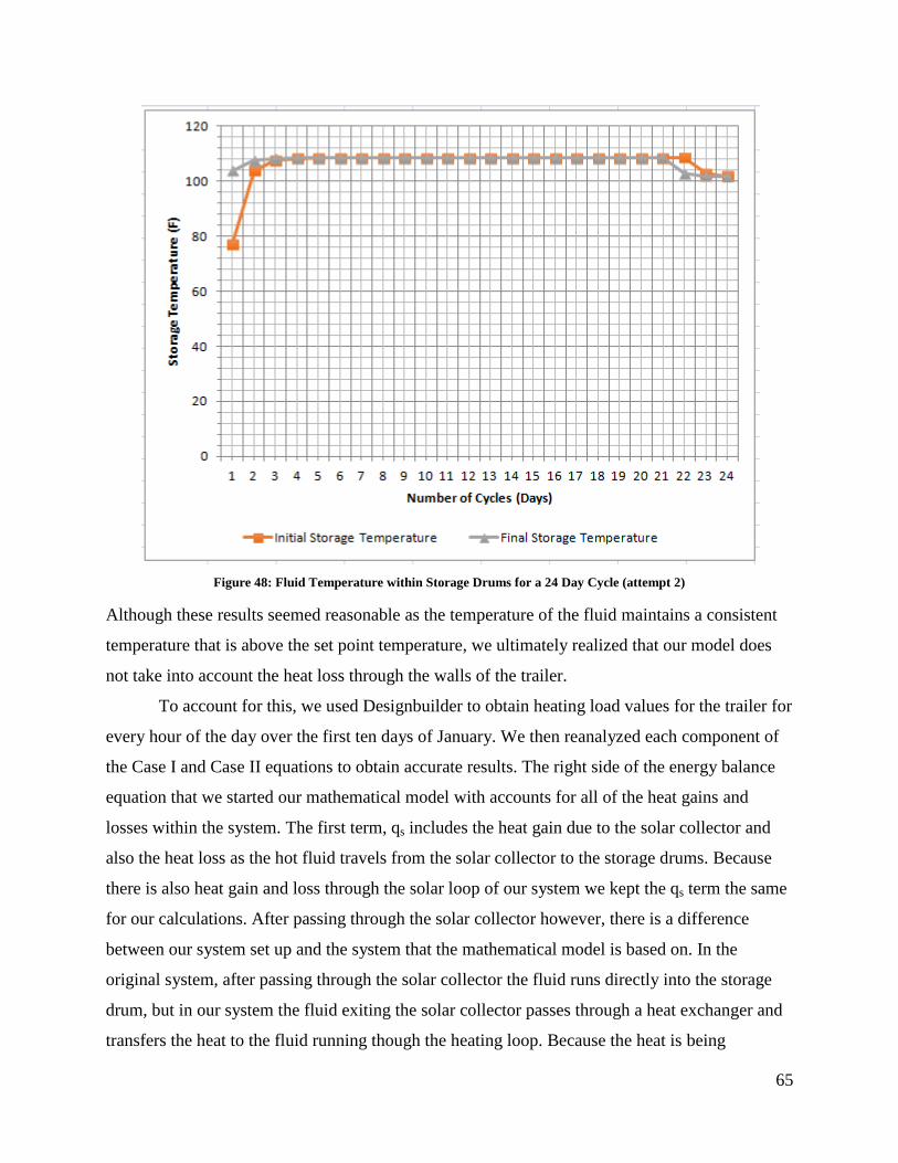
65
Figure 48: Fluid Temperature within Storage Drums for a 24 Day Cycle (attempt 2)
Although these results seemed reasonable as the temperature of the fluid maintains a consistent
temperature that is above the set point temperature, we ultimately realized that our model does
not take into account the heat loss through the walls of the trailer.
To account for this, we used Designbuilder to obtain heating load values for the trailer for
every hour of the day over the first ten days of January. We then reanalyzed each component of
the Case I and Case II equations to obtain accurate results. The right side of the energy balance
equation that we started our mathematical model with accounts for all of the heat gains and
losses within the system. The first term, qs includes the heat gain due to the solar collector and
also the heat loss as the hot fluid travels from the solar collector to the storage drums. Because
there is also heat gain and loss through the solar loop of our system we kept the qs term the same
for our calculations. After passing through the solar collector however, there is a difference
between our system set up and the system that the mathematical model is based on. In the
original system, after passing through the solar collector the fluid runs directly into the storage
drum, but in our system the fluid exiting the solar collector passes through a heat exchanger and
transfers the heat to the fluid running though the heating loop. Because the heat is being
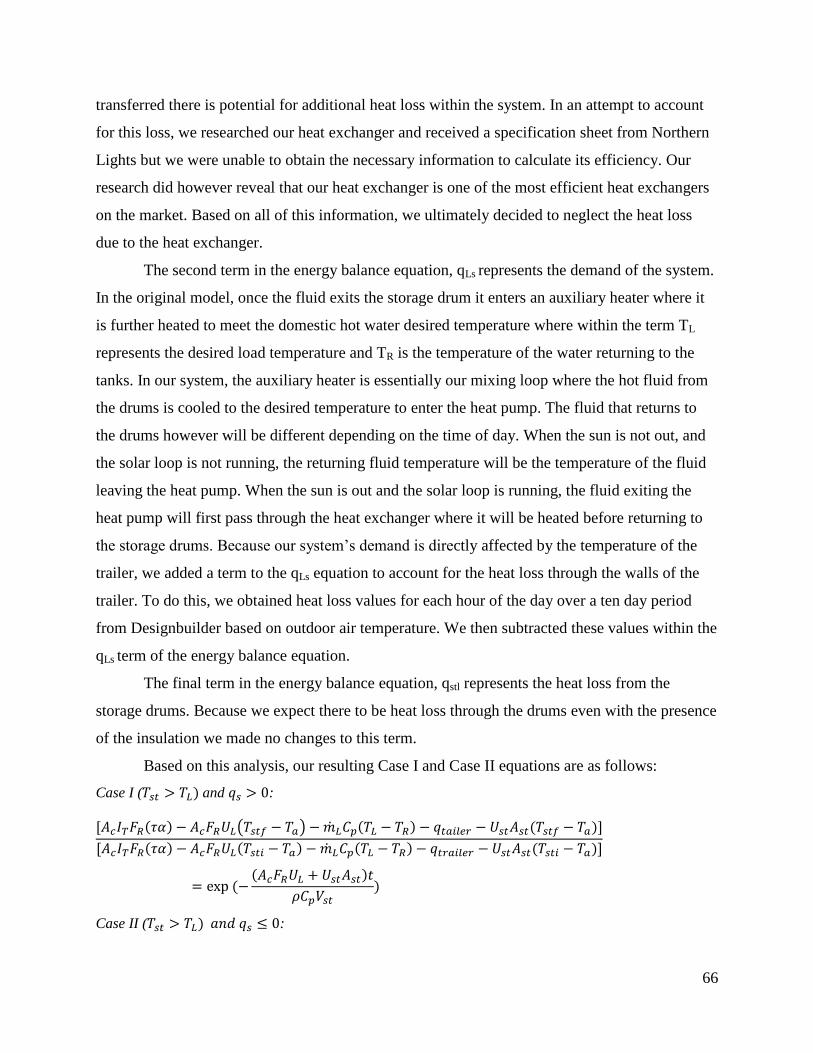
66
transferred there is potential for additional heat loss within the system. In an attempt to account
for this loss, we researched our heat exchanger and received a specification sheet from Northern
Lights but we were unable to obtain the necessary information to calculate its efficiency. Our
research did however reveal that our heat exchanger is one of the most efficient heat exchangers
on the market. Based on all of this information, we ultimately decided to neglect the heat loss
due to the heat exchanger.
The second term in the energy balance equation, qLs represents the demand of the system.
In the original model, once the fluid exits the storage drum it enters an auxiliary heater where it
is further heated to meet the domestic hot water desired temperature where within the term TL
represents the desired load temperature and TR is the temperature of the water returning to the
tanks. In our system, the auxiliary heater is essentially our mixing loop where the hot fluid from
the drums is cooled to the desired temperature to enter the heat pump. The fluid that returns to
the drums however will be different depending on the time of day. When the sun is not out, and
the solar loop is not running, the returning fluid temperature will be the temperature of the fluid
leaving the heat pump. When the sun is out and the solar loop is running, the fluid exiting the
heat pump will first pass through the heat exchanger where it will be heated before returning to
the storage drums. Because our system’s demand is directly affected by the temperature of the
trailer, we added a term to the qLs equation to account for the heat loss through the walls of the
trailer. To do this, we obtained heat loss values for each hour of the day over a ten day period
from Designbuilder based on outdoor air temperature. We then subtracted these values within the
qLs term of the energy balance equation.
The final term in the energy balance equation, qstl represents the heat loss from the
storage drums. Because we expect there to be heat loss through the drums even with the presence
of the insulation we made no changes to this term.
Based on this analysis, our resulting Case I and Case II equations are as follows:
Case I ( and :
Case II ( :
67
We then solved for the final storage temperature and graphed the results. Our resulting graph suggested
that our system was not properly sized and in order to determine the best collector and drum sizes we
adjusted their values until a reasonable graph resulted. Because the heat pump can run in heating mode at
input temperatures between 40oF and 77
oF, we assumed a reasonable graph to be one in which the
temperature within the drums never dropped below 40oF.
5.2.6 System Design
Our system design was created through a combination of research and a series of
consultations with Professor Elovitz. Because the solar collector that we purchased also included
all of the components needed for the solar loop, that part of our system design was based on the
system set up provided to us by Northern Lights. For our heating loop we created many iterations
of the design and each time had it reviewed by Professor Elovitz. Our first iteration consisted of
the four hot water storage drums connected to the heat exchanger and heat pump on either side. It
was then decided that additional circulating pumps would be necessary and the introduction of a
pressure relief valve and air relief valve should be made. We talked through the location of the
pumps and valves and also discussed the need for an expansion tank. As these components were
incorporated to increase the safety of the system, we also considered how hot the fluid in the
drums could potentially become and looked into the maximum operating temperature of the heat
pump. We found the maximum fluid temperature intake on the heat pump to be 77oF which was
a lot lower than our anticipated storage fluid temperature. To account for this we formulated the
idea of incorporating a mixing valve to mix the incoming hot fluid with the cold fluid exiting the
heat pump in order to obtain the optimal temperature. We then considered that the heat pump
will most likely not be needed to continuously heat at all times, thus we incorporated the three
way motorized valve to create two separate system modes: heating and charging. Finally, we
discussed the inclusion of check valves and ball valves in order to prevent backflow and be able
to manually restrict flow. Our final system design, as well as an explanation on how our system
functions is presented in Chapter 4.0.
5.2.7 System Construction
Section 4.1 in the previous chapter describes the construction of our system. In order to
carry out the construction we completed work together as a team, in pairs, and individually.
68
5.2.8 Electrical Design and Controls
In order to provide power to our system, we collected data on each of the components
that required power. These components were the two Wilo Star pumps, the march pump, the heat
pump and the three-way motorized valve. Once we obtained this data, we enlisted the help of an
electrician to help us install the electrical components in a safe manner.
Because our system design requires some of the components to run while others may not
need to, we also drafted a pump schedule for the pumps and motorized valve. We accomplished
this by determining (1) when each pump would be on, (2) if there were time and/or temperature
restrictions, and (3) which pumps are dependent on each other. In order to implement our design
with a control system we had our design reviewed by a professor in the Electrical Engineering
department at WPI. Upon showing him our plan and explaining how the system is intended to
work, he informed us that our system requires a more complex control plan, one that our
collective knowledge would not allow. We sought help from a couple of different experts in the
field, but were unable to completely solve our problem in the time allotted for the project.
However, for the purposes of this project, we included a tentative control schematic that could be
pursued in the future.
5.3 Objective 3: Feasibility of Unity Home Integration
Using the original model that we designed in DesignBuilder for the Xyla platform and
our DesignBuilder model for our solar water heating system we aimed to predict the
effectiveness of our system within a Unity Home. We attempted this by changing the HVAC
settings within the program for our model of the Xyla platform from simple to detailed. In doing
so, DesignBuilder calculates loads differently; instead of using an idealized HVAC system that
always reaches the defined set point temperature, as the system does when the HVAC is set to
simple, the components of our system were inserted and the system was run until it reached the
set point temperature. Upon running this simulation, DesignBuilder outputs data on how the
system performed, which includes a table depicting how many hours throughout the day our
system was not able to reach the defined set point temperature. These results would allow us to
determine if our system is a feasible option for a Unity Home.
In addition to using DesignBuilder, we also our mathematical model established in
Objective 2. We made adjustments to our model by inputting values associated with the Xyla
69
platform and again changed the solar collector size and storage drum volume until we obtained
an adequately sized system to meet the demand required by the home.
5.4 Objective 4: Develop a Set of Strategies and Recommendations
Using information gathered from our background research, energy modeling and the
construction of our system we were able to make recommendations for Unity Homes and for
future WPI students. From our energy modeling to investigate the potential for passive
improvements to Unity Home’s houses we were able to make definitive conclusions about their
design and construction process and formulated recommendations to reflect our findings. The
design and testing of our system within the trailer and in DesignBuilder revealed potential flaws
with the system which allowed us to prepare recommendations on how to improve the system.
Additionally, we developed ideas on how to improve our system that could be implemented by
WPI students in future projects. Finally, our system integration with a Unity Homes house
allowed us to analyze the potential of our system for use within a home and helped us develop
recommendations on the system’s integration.

70
6.0 Results
The following Chapter presents our results from each of our objectives as described in
our Methodology chapter.
6.1 Objective 1: Improve the Design of a Unity Home Using Passive Methods
Windows
Error! Reference source not found. shows the district heating and design day load of
the home for four different window types.
Table 1: Comparison of Window Types
Base Design
(Trp low-e
(e2=.2) Clr
3mm/13mm)
Double Pane
(Dbl low-e (e2=.2)
Clr 3mm/13mm Air)
Triple Pane w/ film
(Trp Bronze [44]
6mm/6mm Arg)
Quadruple Pane
(Qdp low-e
3mm/8mm Krypton)
District
Heating
(kBtu/year)
16351 17836 20775 16454
Design Day
(kBtu/h) 15.44 18.16 16.43 15.42
In all of their homes Unity Homes use low-e triple pane windows which are represented by the
“Base Design” column in the table. Although we found that the quadruple pane window is better
at holding in heat, resulting in less heat required on a design day, using quadruple pane windows
results in a greater district heating load. This occurs because quadruple pane windows block out
more sunlight resulting in less passive heat gain from the sun which ultimately requires an
increase in mechanical heating. Because of this the triple pane low-e windows that Unity Homes
already use are the most efficient and cost effective option from what we have tested.
Insulation
Error! Reference source not found. shows the district heating and design day load of
the home for four different R-value wall insulations.
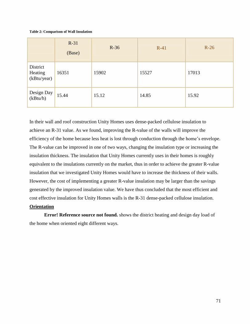
71
Table 2: Comparison of Wall Insulation
R-31
(Base) R-36 R-41 R-26
District
Heating
(kBtu/year)
16351 15902 15527 17013
Design Day
(kBtu/h) 15.44 15.12 14.85 15.92
In their wall and roof construction Unity Homes uses dense-packed cellulose insulation to
achieve an R-31 value. As we found, improving the R-value of the walls will improve the
efficiency of the home because less heat is lost through conduction through the home’s envelope.
The R-value can be improved in one of two ways, changing the insulation type or increasing the
insulation thickness. The insulation that Unity Homes currently uses in their homes is roughly
equivalent to the insulations currently on the market, thus in order to achieve the greater R-value
insulation that we investigated Unity Homes would have to increase the thickness of their walls.
However, the cost of implementing a greater R-value insulation may be larger than the savings
generated by the improved insulation value. We have thus concluded that the most efficient and
cost effective insulation for Unity Homes walls is the R-31 dense-packed cellulose insulation.
Orientation
Error! Reference source not found. shows the district heating and design day load of
the home when oriented eight different ways.
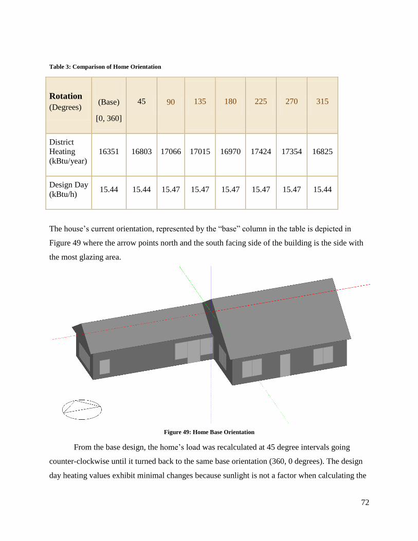
72
Table 3: Comparison of Home Orientation
Rotation
(Degrees)
(Base)
[0, 360]
45 90 135 180 225 270 315
District
Heating
(kBtu/year)
16351 16803 17066 17015 16970 17424 17354 16825
Design Day
(kBtu/h) 15.44 15.44 15.47 15.47 15.47 15.47 15.47 15.44
The house’s current orientation, represented by the “base” column in the table is depicted in
Figure 49 where the arrow points north and the south facing side of the building is the side with
the most glazing area.
Figure 49: Home Base Orientation
From the base design, the home’s load was recalculated at 45 degree intervals going
counter-clockwise until it turned back to the same base orientation (360, 0 degrees). The design
day heating values exhibit minimal changes because sunlight is not a factor when calculating the
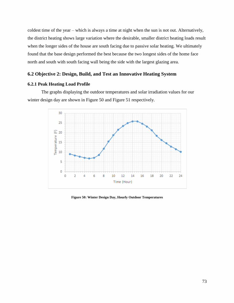
73
coldest time of the year – which is always a time at night when the sun is not out. Alternatively,
the district heating shows large variation where the desirable, smaller district heating loads result
when the longer sides of the house are south facing due to passive solar heating. We ultimately
found that the base design performed the best because the two longest sides of the home face
north and south with south facing wall being the side with the largest glazing area.
6.2 Objective 2: Design, Build, and Test an Innovative Heating System
6.2.1 Peak Heating Load Profile
The graphs displaying the outdoor temperatures and solar irradiation values for our
winter design day are shown in Figure 50 and Figure 51 respectively.
Figure 50: Winter Design Day, Hourly Outdoor Temperatures
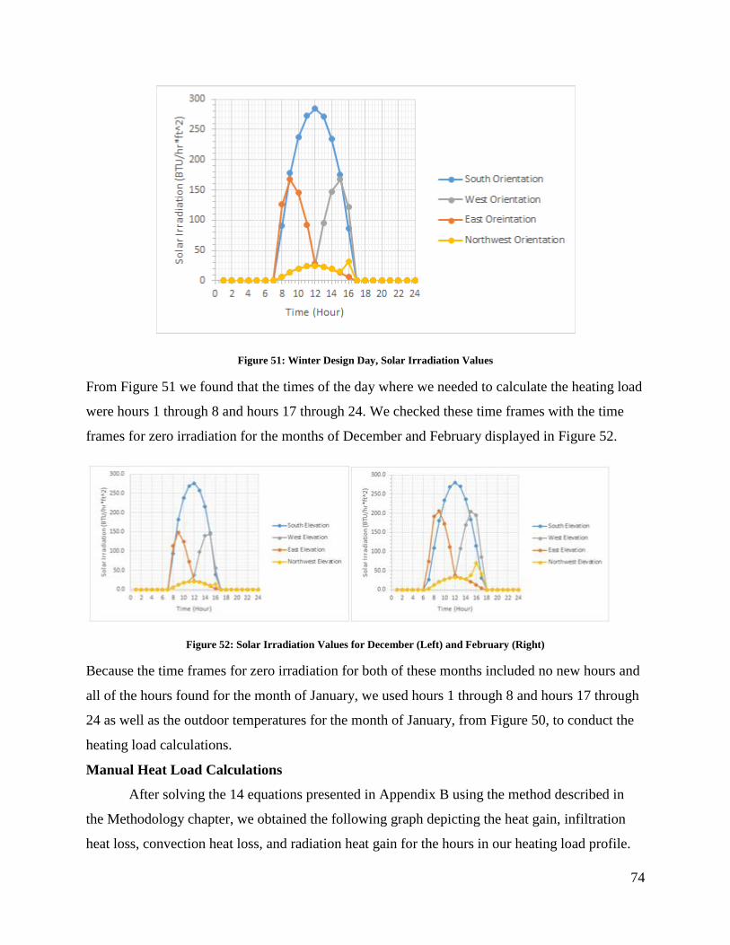
74
Figure 51: Winter Design Day, Solar Irradiation Values
From Figure 51 we found that the times of the day where we needed to calculate the heating load
were hours 1 through 8 and hours 17 through 24. We checked these time frames with the time
frames for zero irradiation for the months of December and February displayed in Figure 52.
Figure 52: Solar Irradiation Values for December (Left) and February (Right)
Because the time frames for zero irradiation for both of these months included no new hours and
all of the hours found for the month of January, we used hours 1 through 8 and hours 17 through
24 as well as the outdoor temperatures for the month of January, from Figure 50, to conduct the
heating load calculations.
Manual Heat Load Calculations
After solving the 14 equations presented in Appendix B using the method described in
the Methodology chapter, we obtained the following graph depicting the heat gain, infiltration
heat loss, convection heat loss, and radiation heat gain for the hours in our heating load profile.
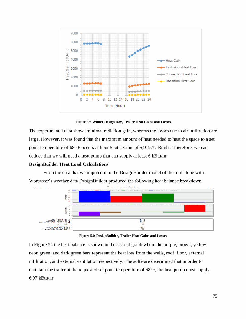
75
Figure 53: Winter Design Day, Trailer Heat Gains and Losses
The experimental data shows minimal radiation gain, whereas the losses due to air infiltration are
large. However, it was found that the maximum amount of heat needed to heat the space to a set
point temperature of 68 °F occurs at hour 5, at a value of 5,919.77 Btu/hr. Therefore, we can
deduce that we will need a heat pump that can supply at least 6 kBtu/hr.
DesignBuilder Heat Load Calculations
From the data that we imputed into the DesignBuilder model of the trail alone with
Worcester’s weather data DesignBuilder produced the following heat balance breakdown.
Figure 54: DesignBuilder, Trailer Heat Gains and Losses
In Figure 54 the heat balance is shown in the second graph where the purple, brown, yellow,
neon green, and dark green bars represent the heat loss from the walls, roof, floor, external
infiltration, and external ventilation respectively. The software determined that in order to
maintain the trailer at the requested set point temperature of 68°F, the heat pump must supply
6.97 kBtu/hr.
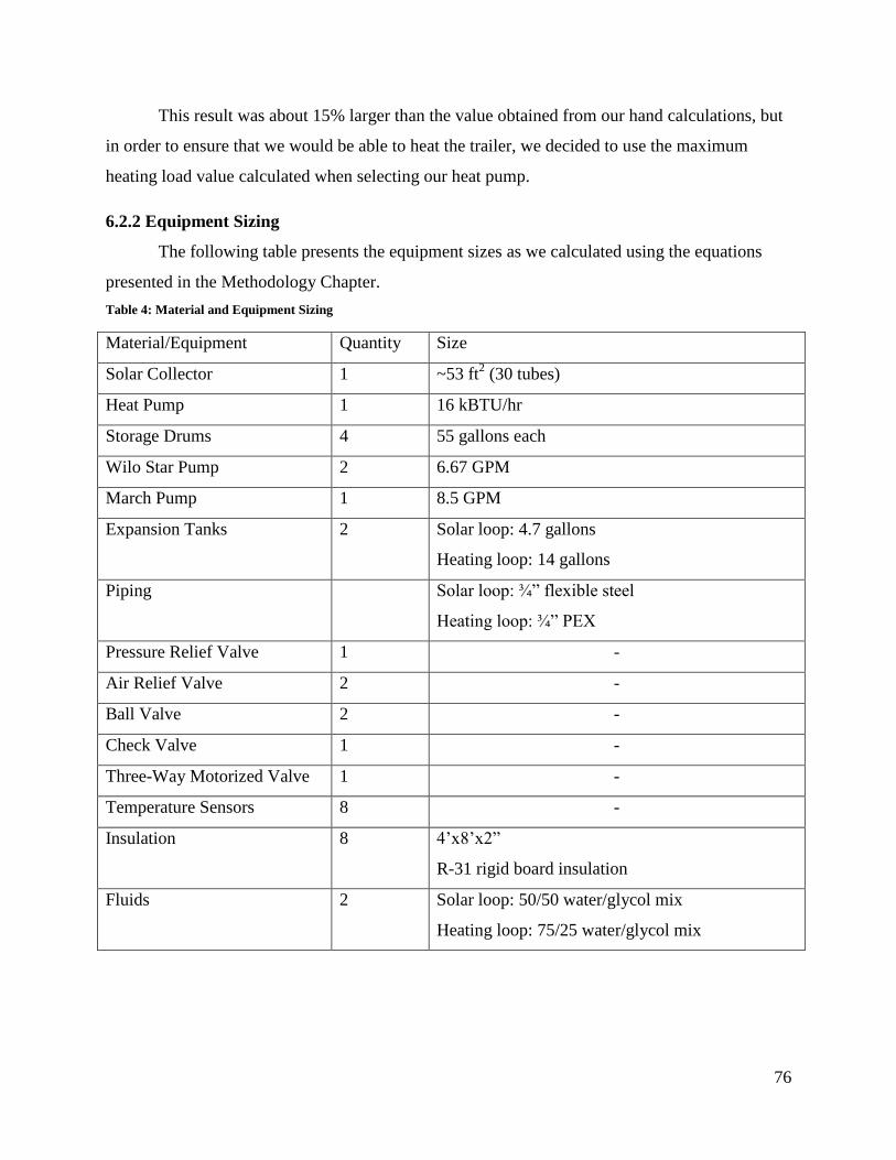
76
This result was about 15% larger than the value obtained from our hand calculations, but
in order to ensure that we would be able to heat the trailer, we decided to use the maximum
heating load value calculated when selecting our heat pump.
6.2.2 Equipment Sizing
The following table presents the equipment sizes as we calculated using the equations
presented in the Methodology Chapter.
Table 4: Material and Equipment Sizing
Material/Equipment Quantity Size
Solar Collector 1 ~53 ft2 (30 tubes)
Heat Pump 1 16 kBTU/hr
Storage Drums 4 55 gallons each
Wilo Star Pump 2 6.67 GPM
March Pump 1 8.5 GPM
Expansion Tanks 2 Solar loop: 4.7 gallons
Heating loop: 14 gallons
Piping Solar loop: ¾” flexible steel
Heating loop: ¾” PEX
Pressure Relief Valve 1 -
Air Relief Valve 2 -
Ball Valve 2 -
Check Valve 1 -
Three-Way Motorized Valve 1 -
Temperature Sensors 8 -
Insulation 8 4’x8’x2”
R-31 rigid board insulation
Fluids 2 Solar loop: 50/50 water/glycol mix
Heating loop: 75/25 water/glycol mix
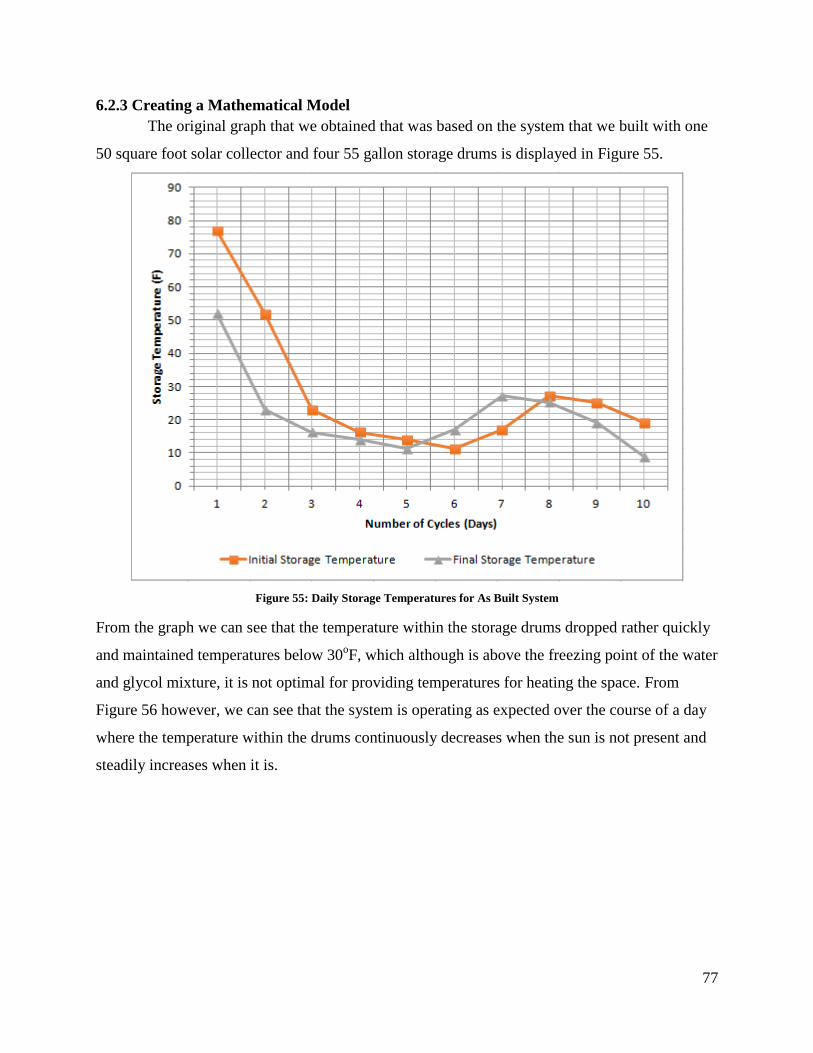
77
6.2.3 Creating a Mathematical Model
The original graph that we obtained that was based on the system that we built with one
50 square foot solar collector and four 55 gallon storage drums is displayed in Figure 55.
Figure 55: Daily Storage Temperatures for As Built System
From the graph we can see that the temperature within the storage drums dropped rather quickly
and maintained temperatures below 30oF, which although is above the freezing point of the water
and glycol mixture, it is not optimal for providing temperatures for heating the space. From
Figure 56 however, we can see that the system is operating as expected over the course of a day
where the temperature within the drums continuously decreases when the sun is not present and
steadily increases when it is.
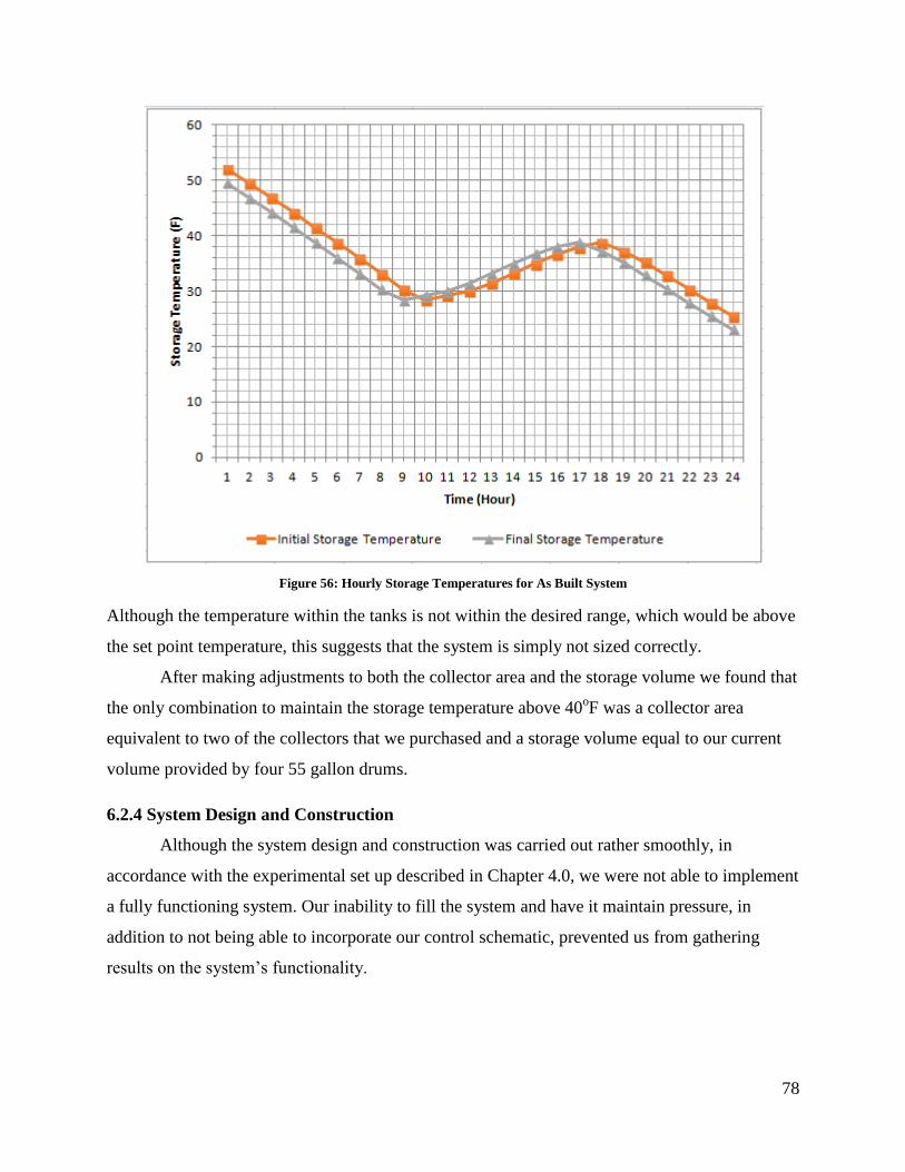
78
Figure 56: Hourly Storage Temperatures for As Built System
Although the temperature within the tanks is not within the desired range, which would be above
the set point temperature, this suggests that the system is simply not sized correctly.
After making adjustments to both the collector area and the storage volume we found that
the only combination to maintain the storage temperature above 40oF was a collector area
equivalent to two of the collectors that we purchased and a storage volume equal to our current
volume provided by four 55 gallon drums.
6.2.4 System Design and Construction
Although the system design and construction was carried out rather smoothly, in
accordance with the experimental set up described in Chapter 4.0, we were not able to implement
a fully functioning system. Our inability to fill the system and have it maintain pressure, in
addition to not being able to incorporate our control schematic, prevented us from gathering
results on the system’s functionality.
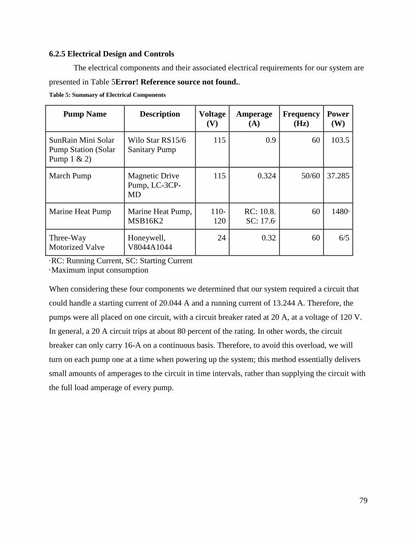
79
6.2.5 Electrical Design and Controls
The electrical components and their associated electrical requirements for our system are
presented in Table 5Error! Reference source not found..
Table 5: Summary of Electrical Components
Pump Name Description Voltage
(V)
Amperage
(A)
Frequency
(Hz)
Power
(W)
SunRain Mini Solar
Pump Station (Solar
Pump 1 & 2)
Wilo Star RS15/6
Sanitary Pump
115 0.9 60 103.5
March Pump Magnetic Drive
Pump, LC-3CP-
MD
115 0.324 50/60 37.285
Marine Heat Pump Marine Heat Pump,
MSB16K2
110-
120
RC: 10.8.
SC: 17.6a
60 1480b
Three-Way
Motorized Valve
Honeywell,
V8044A1044
24 0.32 60 6/5
a RC: Running Current, SC: Starting Current b Maximum input consumption
When considering these four components we determined that our system required a circuit that
could handle a starting current of 20.044 A and a running current of 13.244 A. Therefore, the
pumps were all placed on one circuit, with a circuit breaker rated at 20 A, at a voltage of 120 V.
In general, a 20 A circuit trips at about 80 percent of the rating. In other words, the circuit
breaker can only carry 16-A on a continuous basis. Therefore, to avoid this overload, we will
turn on each pump one at a time when powering up the system; this method essentially delivers
small amounts of amperages to the circuit in time intervals, rather than supplying the circuit with
the full load amperage of every pump.
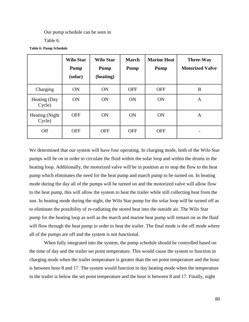
80
Our pump schedule can be seen in
Table 6.
Table 6: Pump Schedule
Wilo Star
Pump
(solar)
Wilo Star
Pump
(heating)
March
Pump
Marine Heat
Pump
Three-Way
Motorized Valvea
Charging ON ON OFF OFF B
Heating (Day
Cycle)
ON ON ON ON A
Heating (Night
Cycle)
OFF ON ON ON A
Off OFF OFF OFF OFF -
We determined that our system will have four operating. In charging mode, both of the Wilo Star
pumps will be on in order to circulate the fluid within the solar loop and within the drums in the
heating loop. Additionally, the motorized valve will be in position as to stop the flow to the heat
pump which eliminates the need for the heat pump and march pump to be turned on. In heating
mode during the day all of the pumps will be turned on and the motorized valve will allow flow
to the heat pump, this will allow the system to heat the trailer while still collecting heat from the
sun. In heating mode during the night, the Wilo Star pump for the solar loop will be turned off as
to eliminate the possibility of re-radiating the stored heat into the outside air. The Wilo Star
pump for the heating loop as well as the march and marine heat pump will remain on as the fluid
will flow through the heat pump in order to heat the trailer. The final mode is the off mode where
all of the pumps are off and the system is not functional.
When fully integrated into the system, the pump schedule should be controlled based on
the time of day and the trailer set point temperature. This would cause the system to function in
charging mode when the trailer temperature is greater than the set point temperature and the hour
is between hour 8 and 17. The system would function in day heating mode when the temperature
in the trailer is below the set point temperature and the hour is between 8 and 17. Finally, night
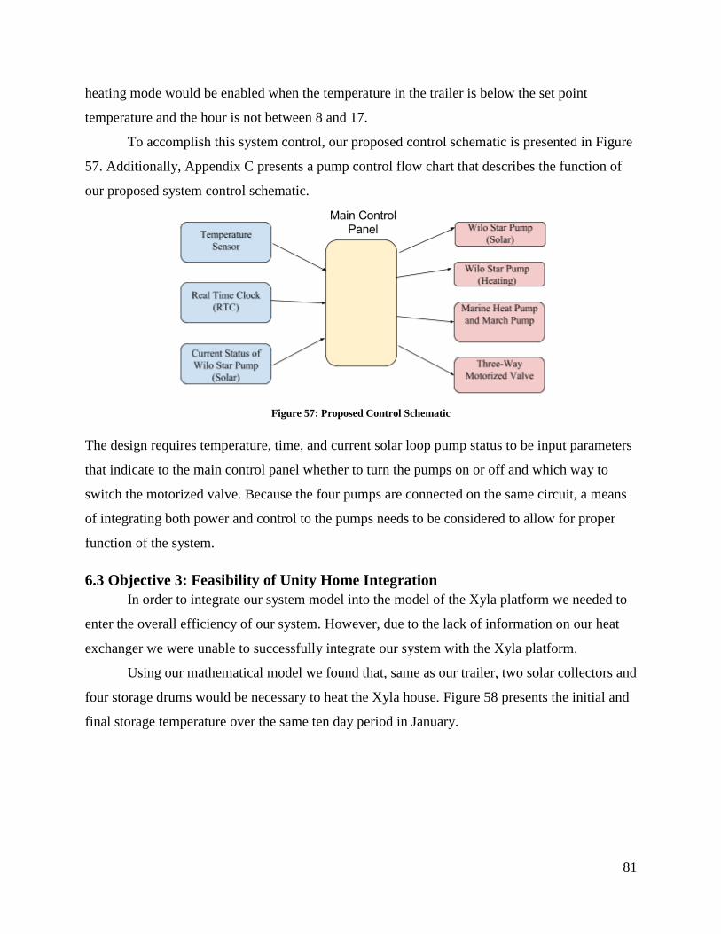
81
heating mode would be enabled when the temperature in the trailer is below the set point
temperature and the hour is not between 8 and 17.
To accomplish this system control, our proposed control schematic is presented in Figure
57. Additionally, Appendix C presents a pump control flow chart that describes the function of
our proposed system control schematic.
Figure 57: Proposed Control Schematic
The design requires temperature, time, and current solar loop pump status to be input parameters
that indicate to the main control panel whether to turn the pumps on or off and which way to
switch the motorized valve. Because the four pumps are connected on the same circuit, a means
of integrating both power and control to the pumps needs to be considered to allow for proper
function of the system.
6.3 Objective 3: Feasibility of Unity Home Integration
In order to integrate our system model into the model of the Xyla platform we needed to
enter the overall efficiency of our system. However, due to the lack of information on our heat
exchanger we were unable to successfully integrate our system with the Xyla platform.
Using our mathematical model we found that, same as our trailer, two solar collectors and
four storage drums would be necessary to heat the Xyla house. Figure 58 presents the initial and
final storage temperature over the same ten day period in January.
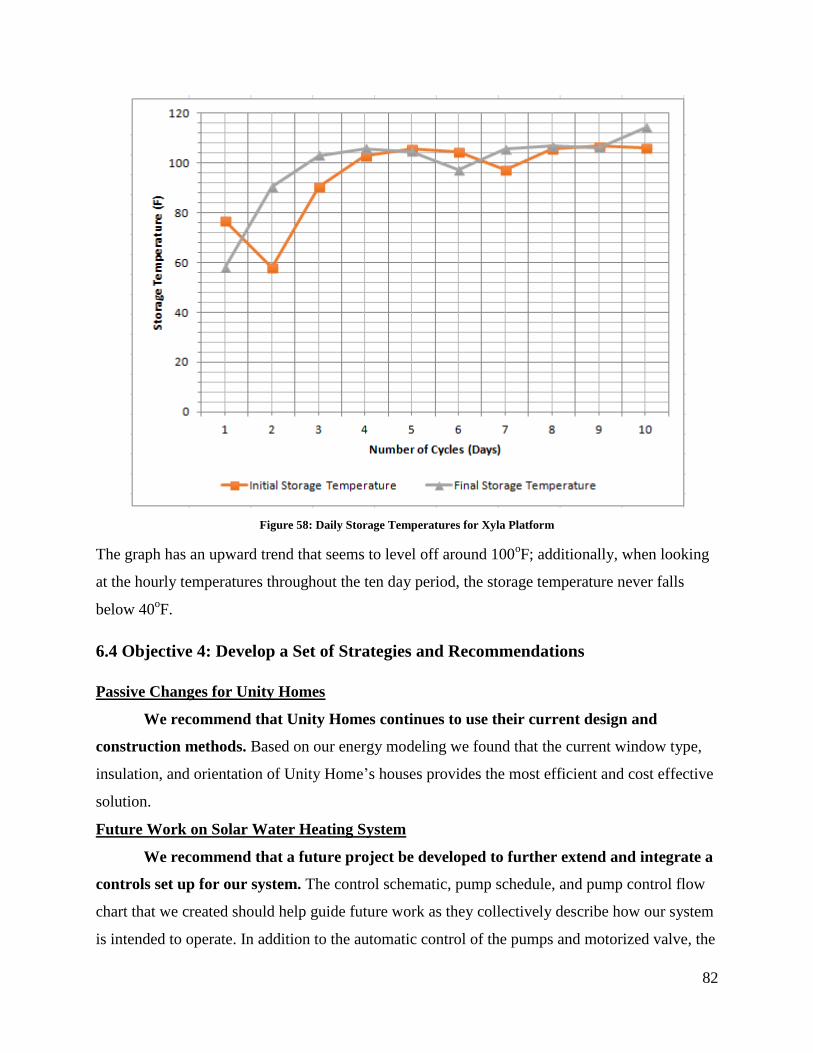
82
Figure 58: Daily Storage Temperatures for Xyla Platform
The graph has an upward trend that seems to level off around 100oF; additionally, when looking
at the hourly temperatures throughout the ten day period, the storage temperature never falls
below 40oF.
6.4 Objective 4: Develop a Set of Strategies and Recommendations
Passive Changes for Unity Homes
We recommend that Unity Homes continues to use their current design and
construction methods. Based on our energy modeling we found that the current window type,
insulation, and orientation of Unity Home’s houses provides the most efficient and cost effective
solution.
Future Work on Solar Water Heating System
We recommend that a future project be developed to further extend and integrate a
controls set up for our system. The control schematic, pump schedule, and pump control flow
chart that we created should help guide future work as they collectively describe how our system
is intended to operate. In addition to the automatic control of the pumps and motorized valve, the
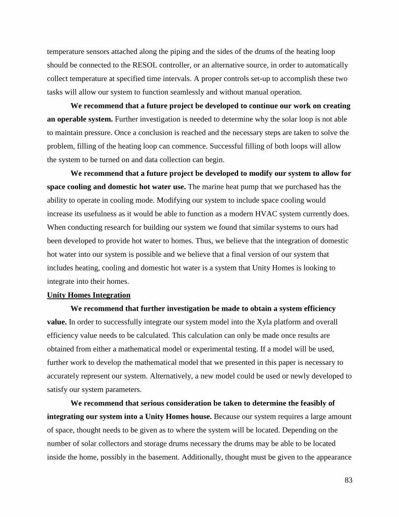
83
temperature sensors attached along the piping and the sides of the drums of the heating loop
should be connected to the RESOL controller, or an alternative source, in order to automatically
collect temperature at specified time intervals. A proper controls set-up to accomplish these two
tasks will allow our system to function seamlessly and without manual operation.
We recommend that a future project be developed to continue our work on creating
an operable system. Further investigation is needed to determine why the solar loop is not able
to maintain pressure. Once a conclusion is reached and the necessary steps are taken to solve the
problem, filling of the heating loop can commence. Successful filling of both loops will allow
the system to be turned on and data collection can begin.
We recommend that a future project be developed to modify our system to allow for
space cooling and domestic hot water use. The marine heat pump that we purchased has the
ability to operate in cooling mode. Modifying our system to include space cooling would
increase its usefulness as it would be able to function as a modern HVAC system currently does.
When conducting research for building our system we found that similar systems to ours had
been developed to provide hot water to homes. Thus, we believe that the integration of domestic
hot water into our system is possible and we believe that a final version of our system that
includes heating, cooling and domestic hot water is a system that Unity Homes is looking to
integrate into their homes.
Unity Homes Integration
We recommend that further investigation be made to obtain a system efficiency
value. In order to successfully integrate our system model into the Xyla platform and overall
efficiency value needs to be calculated. This calculation can only be made once results are
obtained from either a mathematical model or experimental testing. If a model will be used,
further work to develop the mathematical model that we presented in this paper is necessary to
accurately represent our system. Alternatively, a new model could be used or newly developed to
satisfy our system parameters.
We recommend that serious consideration be taken to determine the feasibly of
integrating our system into a Unity Homes house. Because our system requires a large amount
of space, thought needs to be given as to where the system will be located. Depending on the
number of solar collectors and storage drums necessary the drums may be able to be located
inside the home, possibly in the basement. Additionally, thought must be given to the appearance
84
of the system and whether or not a roof mounted solar collector will be favorable over a ground
mounted system.
We recommend that a cost analysis be performed to compare our systems costs with
the cost of the HVAC system already used within a Unity Home. Taking into account both
the initial cost of the system as well as the cost savings allowed by the elimination of electric or
gas consumption a cost analysis can be performed. This analysis will further illustrate the
feasibility of the integration of our system. Additionally, calculations and an associated cost
analysis can be performed for our system with the addition of using solar panels as a means to
power our system. This addition to our system would not only provide potential long term cost
savings, it would also create an HVAC system to help in achieving a net zero energy house
design.
85
Conclusions
The goal of our project was to improve Unity Home’s home design by investigating both
passive and active methods. We conducted research, performed energy modeling analyses, and
built a solar water heating system to formulate recommendations for Unity Homes and future
WPI students. Our research assisted us in choosing variables to consider when attempting to
passively improve Unity Home’s design. The energy modeling that we performed to accomplish
this allowed us to conclude that Unity Home’s current design and construction techniques are the
most efficient and cost effective. When considering active improvements we were able to
conclude that our system would need to include an additional solar collector in order to
effectively heat either the trailer or the Xyla house. We were also able to formulate many
recommendations to assist future WPI project teams that continue our work as they outline our
intentions for successfully completing of our work as well as additional topics to investigate
upon obtaining further results.
86
References
(2015). Retrieved from http://scienceline.ucsb.edu/getkey.php?key=1464: UCSB ScienceLine.
A Better Way to Build. (n.d.). Retrieved from http://unityhomes.com/: Unity Homes.
Active Solar Systems. (n.d.). Retrieved from http://www.usc.edu/dept-
00/dept/architecture/mbs/tools/thermal/controls_activesolar.html.
Active System. (n.d.). www.engineering-dictionary.org/ACTIVE_SYSTEM.
Bainbridge, D. A. (2005). A Water Wall Solar Design Manual. Retrieved
from http://www.builditsolar.com/Projects/SpaceHeating/AWaterWallIntro.pdf.
Building a Better Trombe Wall. (n.d.). Retrieved
from http://www.nrel.gov/docs/legosti/fy98/22834.pdf: NREL.
Congress, U. S. (2007). Energy Independence and Security Act of 2007. Washington, DC.
Daylighting. (n.d.). Retrieved from https://energy.gov/energysaver/daylighting: energy.gov.
de Gracia L.F. Cabeza, A. (2015). Phase Change Materials and Thermal Energy Storage for
Buildings. https://beopt.nrel.gov/sites/beopt.nrel.gov/files/Alvaro%20&%20Garcia,%202
015%20-
%20Phase%20change%20materials%20and%20thermal%20energy%20storage%20for%
20buildings.pdf.
Dimock, L. (2013). Your Home Electrical System. Retrieved
from http://www.thecircuitdetective.com/bkgrd.htm.
Domestic Solar Water Heating Installation Manual. (n.d.). Northern Lights.
Evacuated Tube Collector. (2017). Retrieved from http://www.alternative-energy-
tutorials.com/solar-hot-water/evacuated-tube-collector.html: Alternative Energy
Tutuorials.
Fallahi, A. (2016). Load Calculations and Principles-Quasi-Steady-State.
Geothermal Heating and Cooling. (n.d.). Retrieved
from http://groundsourcewi.com/geothermal: Ground Source.
Harris, C. (1991). U.S.A Patent No. https://www.google.com/patents/US4993483.
International Living Future Institute. (2017). Net Zero Energy Building. Retrieved
from https://living-future.org/net-zero/.
87
Jafarkazemi, F., & Abdi, H. (2012). Evacuated Tube Solar Heat Pipe Collector Model and
Associated Tests. Journal of Renewable and Sustainable Energy, 4(023101).
Jones, B. (2013). Flat Plate Solar Thermal Collectors: Overview. Retrieved from
http://thegreenhome.co.uk/heating-renewables/solar-panels/flat-plate-solar-thermal-
collectors-overview/: The Green Home Construction & Lifestyle.
Kulkami, G. N., Kedare, S. B., & Bandyopadhyay, S. (2006). Determination of Design Space
and Optimization of Solar Water Heating Systems. Solar Energy, 81(8), 958-968.
McNabb, N. (2013). Strategies to Achieve Net-Zero Energy Homes: A Framework for Future
Guidelines. Retrieved from
http://nvlpubs.nist.gov/nistpubs/SpecialPublications/NIST.SP.1140.pdf: National Institute
of Standards and Technology.
Measuring Solar Thermal Energy. (2012). Retrieved from http://www.home-energy-
metering.com/solar-thermal-energy.html: UtilEcon Services, LLC.
Meyers, R. J., Williams, E. D., & Matthews, H. S. (2010). Scoping the Potential of Monitoring
and Control Technologies to Reduce Energy use in Homes. Paper presented at the Energy
and Buildings.
Passive House Certification Criteria. (n.d.). Retrieved from https://passivehouse-
international.org/index.php?page_id=150: International Passive House Association.
Reardon, C. (n.d.). Thermal Mass. Retrieved from http://www.yourhome.gov.au/passive-
design/thermal-mass: Australian Government.
Sedra, A. S., & Smith, K. C. (2014). Microelectronic Circuits (7th edition ed.): Oxford
University Press.
Solar Geyser Technology Explained. (n.d.). Retrieved from http://www.solarsense.co.za/solar-
water-heating-explained.php: Solar Sense Solar Heating Specialists.
Solar Photovoltaic Technology Basics. (n.d.). Retrieved
from https://www.nrel.gov/workingwithus/re-photovoltaics.html: NREL.
Solar Pool Heating. (n.d.). Retrieved from http://www.alternative-energy-tutorials.com/solar-hot-
water/solar-pool-heating.html: Alternative Energy Tutorials.
Solar PV Technology. (n.d.). Retrieved
from http://www.altenergy.org/renewables/solar/solartechnolgy.html: Alternative
Energy.
Solar Thermal Water Heating. (n.d.). Retrieved
from http://www.powellrangesolutions.co.uk/services/solar/: Powell Range Solutions.

88
This is LEED: Better Buildings are our Legacy. (n.d.). Retrieved from
http://leed.usgbc.org/leed.html?gclid=Cj0KEQjw6uO-
BRDbzujwtuzAzfkBEiQAAnhJ0Osm_unfbmKTiWoELSqAC_EiGMMngXtfToe5yzS8d
isaApr08P8HAQ: U.S. Green Building Council.
Types of Insulation. (n.d.). Retrieved from https://energy.gov/energysaver/types-
insulation: energy.gov.
Understanding Your Home Electrical System. (2015). Retrieved
from http://www.esfi.org/resource/understanding-your-home-electrical-system-
213: Electrical Safety Foundation International.
Window Types. (n.d.). Retrieved from https://energy.gov/energysaver/window-
types: energy.gov.
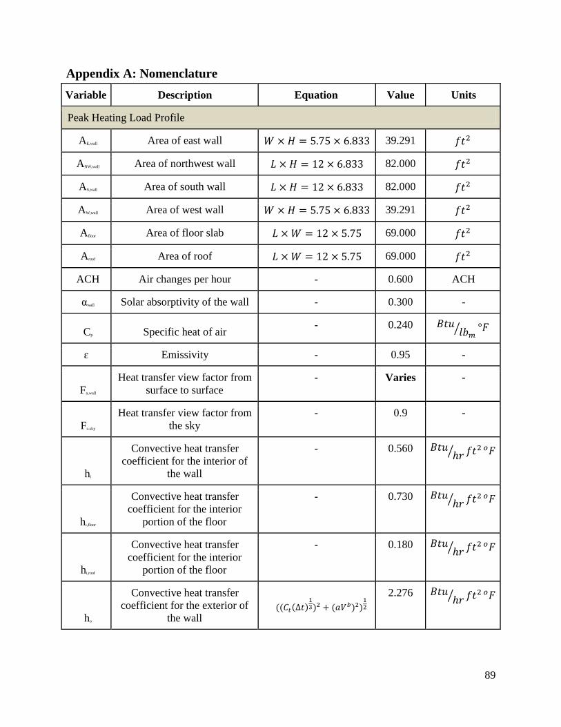
89
Appendix A: Nomenclature
Variable Description Equation Value Units
Peak Heating Load Profile
AE,wall Area of east wall 39.291
ANW,wall Area of northwest wall 82.000
AS,wall Area of south wall 82.000
AW,wall Area of west wall 39.291
Afloor Area of floor slab 69.000
Aroof Area of roof 69.000
ACH Air changes per hour - 0.600 ACH
αwall Solar absorptivity of the wall - 0.300 -
Cp Specific heat of air - 0.240
ɛ Emissivity - 0.95 -
Fa,wall
Heat transfer view factor from
surface to surface
- Varies -
Fs-sky
Heat transfer view factor from
the sky
- 0.9 -
hi
Convective heat transfer
coefficient for the interior of
the wall
- 0.560
hi,floor
Convective heat transfer
coefficient for the interior
portion of the floor
- 0.730
hi,roof
Convective heat transfer
coefficient for the interior
portion of the floor
- 0.180
ho
Convective heat transfer
coefficient for the exterior of
the wall
2.276

90
hr,sky,v
Long wave radiation
coefficient from the sky
Varies
hr,wall,s,nw
Long wave radiation
coefficient from the south and
northwest wall
( )
0.2694
hr,wall,w,e
Long wave radiation
coefficient from the west and
east wall
( )
0.1130
hr,floor
Long wave radiation
coefficient from the roof
( )
0.2025
hr,roof
Long wave radiation
coefficient from the roof
( )
0.2025
mair Mass flow rate of air
22.066
Density of air
- 0.0780
qintGain Internal heat gain - 0
Stefan Boltzmann constant
- 0.1714e-
8
Tavg Average room Temperature - Varies °F
To Outside temperature - Varies °F
Tsky Sky temperature in the winter
To - 10.8
Varies °F
Tsky,v
Sky temperature for vertical
surfaces in the winter
Varies °F
Tr
Temperature inside the trailer
in the winter
- 68 °F
Uwall Heat loss coefficient of walls - 0.5606
Ufloor Heat loss coefficient of floor - 0.5606
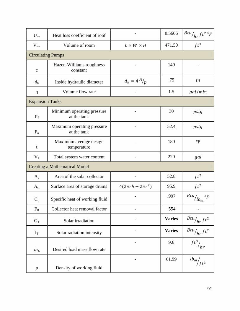
91
Uroof Heat loss coefficient of roof - 0.5606
Vroom Volume of room 471.50
Circulating Pumps
c
Hazen-Williams roughness
constant
- 140 -
dh Inside hydraulic diameter .75
q Volume flow rate - 1.5
Expansion Tanks
Pf
Minimum operating pressure
at the tank
- 30
Po
Maximum operating pressure
at the tank
- 52.4
t
Maximum average design
temperature
- 180
Vg Total system water content - 220
Creating a Mathematical Model
Ac Area of the solar collector - 52.8
Ast Surface area of storage drums 95.9
Cp Specific heat of working fluid - .997
FR Collector heat removal factor - .554 -
GT Solar irradiation - Varies
IT Solar radiation intensity - Varies
Desired load mass flow rate
- 9.6
Density of working fluid
- 61.99
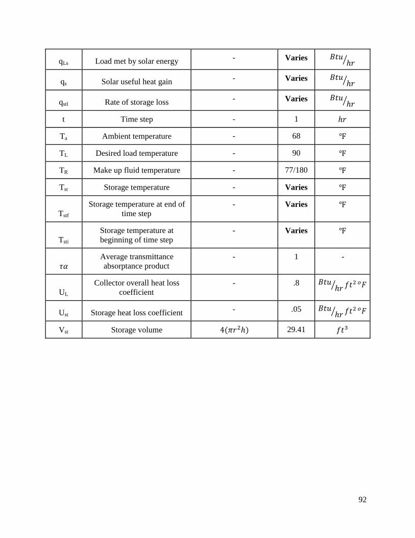
92
qLs Load met by solar energy - Varies
qs Solar useful heat gain - Varies
qstl Rate of storage loss - Varies
t Time step - 1
Ta Ambient temperature - 68
TL Desired load temperature - 90
TR Make up fluid temperature - 77/180
Tst Storage temperature - Varies
Tstf
Storage temperature at end of
time step
- Varies
Tsti
Storage temperature at
beginning of time step
- Varies
Average transmittance
absorptance product
- 1 -
UL
Collector overall heat loss
coefficient
- .8
Ust Storage heat loss coefficient - .05
Vst Storage volume 29.41
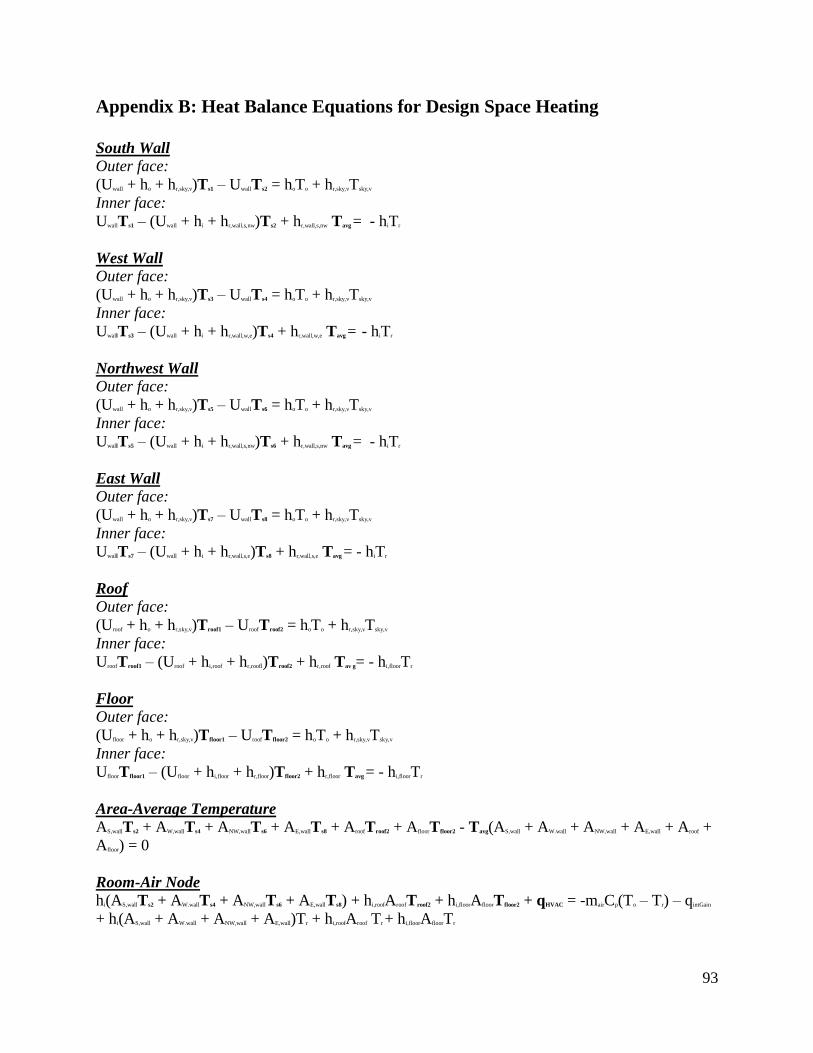
93
Appendix B: Heat Balance Equations for Design Space Heating
South Wall Outer face:
(Uwall + ho + hr,sky,v)Ts1 – UwallTs2 = hoTo + hr,sky,vTsky,v
Inner face:
UwallTs1 – (Uwall + hi + hr,wall,s,nw)Ts2 + hr,wall,s,nw Tavg = - hiTr
West Wall Outer face:
(Uwall + ho + hr,sky,v)Ts3 – UwallTs4 = hoTo + hr,sky,vTsky,v
Inner face:
UwallTs3 – (Uwall + hi + hr,wall,w,e)Ts4 + hr,wall,w,e Tavg = - hiTr
Northwest Wall Outer face:
(Uwall + ho + hr,sky,v)Ts5 – UwallTs6 = hoTo + hr,sky,vTsky,v
Inner face:
UwallTs5 – (Uwall + hi + hr,wall,s,nw)Ts6 + hr,wall,s,nw Tavg = - hiTr
East Wall Outer face:
(Uwall + ho + hr,sky,v)Ts7 – UwallTs8 = hoTo + hr,sky,vTsky,v
Inner face:
UwallTs7 – (Uwall + hi + hr,wall,s,e)Ts8 + hr,wall,s,e Tavg = - hiTr
Roof Outer face:
(Uroof + ho + hr,sky,v)Troof1 – UroofTroof2 = hoTo + hr,sky,vTsky,v
Inner face:
UroofTroof1 – (Uroof + hi,roof + hr,roofl)Troof2 + hr,roof Tav g= - hi,floorTr
Floor Outer face:
(Ufloor + ho + hr,sky,v)Tfloor1 – UroofTfloor2 = hoTo + hr,sky,vTsky,v
Inner face:
UfloorTfloor1 – (Ufloor + hi,floor + hr,floor)Tfloor2 + hr,floor Tavg = - hi,floorTr
Area-Average Temperature AS,wallTs2 + AW,wallTs4 + ANW,wallTs6 + AE,wallTs8 + AroofTroof2 + AfloorTfloor2 - Tavg(AS,wall + AW.wall + ANW,wall + AE,wall + Aroof +
Afloor) = 0
Room-Air Node hi(AS,wallTs2 + AW.wallTs4 + ANW,wallTs6 + AE,wallTs8) + hi,roofAroofTroof2 + hi,floorAfloorTfloor2 + qHVAC = -mairCp(To – Tr) – qintGain
+ hi(AS,wall + AW.wall + ANW,wall + AE,wall)Tr + hi,roofAroof Tr + hi,floorAfloorTr
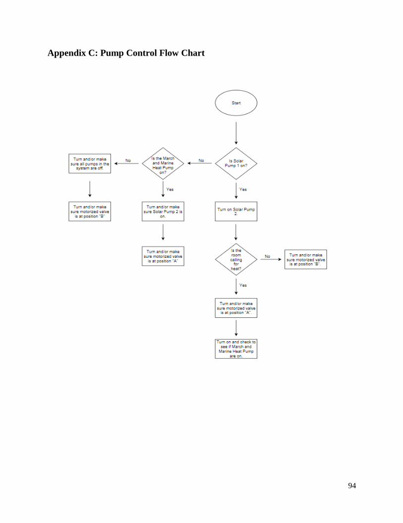
94
Appendix C: Pump Control Flow Chart