Embed Size (px)
Citation preview
ORNL/TM-2017/122 CRADA/NFE-15-05793
Evaluation of Additive Manufacturing for High Volume Composite Part Molds
Chad Duty Vlastimil Kunc Bradley Lokitz Robert Springfield March 3, 2017
CRADA FINAL REPORT NFE-15-05793
Approved for Public Release. Distribution is Unlimited.
DOCUMENT AVAILABILITY Reports produced after January 1, 1996, are generally available free via US Department of Energy (DOE) SciTech Connect. Website http://www.osti.gov/scitech/ Reports produced before January 1, 1996, may be purchased by members of the public from the following source: National Technical Information Service 5285 Port Royal Road Springfield, VA 22161 Telephone 703-605-6000 (1-800-553-6847) TDD 703-487-4639 Fax 703-605-6900 E-mail [email protected] Website http://www.ntis.gov/help/ordermethods.aspx Reports are available to DOE employees, DOE contractors, Energy Technology Data Exchange representatives, and International Nuclear Information System representatives from the following source: Office of Scientific and Technical Information PO Box 62 Oak Ridge, TN 37831 Telephone 865-576-8401 Fax 865-576-5728 E-mail [email protected] Website http://www.osti.gov/contact.html
This report was prepared as an account of work sponsored by an agency of the United States Government. Neither the United States Government nor any agency thereof, nor any of their employees, makes any warranty, express or implied, or assumes any legal liability or responsibility for the accuracy, completeness, or usefulness of any information, apparatus, product, or process disclosed, or represents that its use would not infringe privately owned rights. Reference herein to any specific commercial product, process, or service by trade name, trademark, manufacturer, or otherwise, does not necessarily constitute or imply its endorsement, recommendation, or favoring by the United States Government or any agency thereof. The views and opinions of authors expressed herein do not necessarily state or reflect those of the United States Government or any agency thereof.
ORNL/TM-2017/122 CRADA/NFE-15-05793
Material Science & Technology Division Advanced Manufacturing Office
Evaluation of Additive Manufacturing for High Volume Composite Part Molds
Authors Chad Duty (MDF)
Vlastimil Kunc (MDF) Bradley Lokitz (CNMS)
Robert Springfield (Tru-Design)
Date Published: March 3, 2017
Prepared by OAK RIDGE NATIONAL LABORATORY
Oak Ridge, Tennessee 37831-6283 managed by
UT-BATTELLE, LLC for the
US DEPARTMENT OF ENERGY under contract DE-AC05-00OR22725
Approved For Public Release

v
CONTENTS
Page CONTENTS ........................................................................................................................................... v LIST OF FIGURES ............................................................................................................................... vi ACKNOWLEDGEMENTS ................................................................................................................. vii ABSTRACT ........................................................................................................................................... 1 1. EVALUATION OF ADDITIVE MANUFACTURING FOR HIGH VOLUME COMPOSITE PART MOLDS ....................................................................................................................................... 1
1.1 BACKGROUND .................................................................................................................. 1 1.2 TECHNICAL RESULTS ...................................................................................................... 2
1.2.1 Low Temperature Tooling .................................................................................................... 3 1.2.2 High Temperature Tooling ................................................................................................... 6
1.3 IMPACTS ............................................................................................................................. 9 1.4 CONCLUSIONS ................................................................................................................. 10
2. PARTNER BACKGROUND .......................................................................................................... 11 3. REFERENCES ................................................................................................................................ 13
vi
LIST OF FIGURES
Fig. 1. Cosmetic surface coatings applied by Tru-Design: Shelby Cobra (left), Willis Jeep (right) . ... 2 Fig. 2. Local failure of gel-coat following high temperature cure cycle. ............................................... 3 Fig. 3. Printed mold surface in the (a) “as-printed” condition and (b) following 5-axis machining. .... 3 Fig. 4. Comparison of polyester coatings on (a) as-printed and (b) plasma-treated CF-ABS substrates. ............................................................................................................................................................... 4 Fig. 5. TD Coat RT failure surface on as-printed CF-ABS substrate. ................................................... 4 Fig. 6. Spray application of TD Coat RT onto a vertical face of a printed surface. .............................. 5 Fig. 7. VARTM mold on display at CAMX using TD Coat RT on CF-ABS substrate.4 ...................... 5 Fig. 8. World’s largest solid 3D printed component (Guinness World Record) featuring TD Coat RT. 6 Fig. 9. Gel-coated high temperature mold (a) before and (b) after thermal cycling. ............................. 6 Fig. 10. ATR-FTIR spectra comparison of “as-printed” and “plasma treated” PPS substrates. ............ 7 Fig. 11. PPS high temperature mold after coating with TD Seal HT. .................................................... 8 Fig. 12. PPS high temperature tool bagged for vacuum test. ................................................................. 8 Fig. 13. (a) High temperature molds using TD Seal HT and (b) the resulting composite part............... 9

vii
ACKNOWLEDGEMENTS
This CRADA NFE-15-05793 was conducted as a Technical Collaboration project within the Oak Ridge National Laboratory (ORNL) Manufacturing Demonstration Facility (MDF) sponsored by the US Department of Energy Advanced Manufacturing Office (CPS Agreement Number 24761). Opportunities for MDF technical collaborations are listed in the announcement “Manufacturing Demonstration Facility Technology Collaborations for US Manufacturers in Advanced Manufacturing and Materials Technologies” posted at http://web.ornl.gov/sci/manufacturing/docs/FBO-ORNL-MDF-2013-2.pdf. The goal of technical collaborations is to engage industry partners to participate in short-term, collaborative projects within the Manufacturing Demonstration Facility (MDF) to assess applicability and of new energy efficient manufacturing technologies. Research sponsored by the U.S. Department of Energy, Office of Energy Efficiency and Renewable Energy, Advanced Manufacturing Office, under contract DE-AC05-00OR22725 with UT-Battelle, LLC.
Spectrographic characterization of printed samples was conducted at the Center for Nanophase Materials Sciences, which is a DOE Office of Science User Facility.

viii
1
ABSTRACT
ORNL worked with TruDesign, LLC to develop viable coating solutions to enable the use of large scale 3D printing for both low-temperature and high-temperature composite molds. This project resulted in two commercial products and successfully demonstrated the use of printed molds for autoclave processing for the first time. 1. EVALUATION OF ADDITIVE MANUFACTURING FOR HIGH VOLUME COMPOSITE
PART MOLDS
This phase 2 technical collaboration project (MDF-TC-201-042) was begun on May 2, 2014 and was completed on March 4, 2017. The collaboration partner, Tru-Design, LLC is a small business. This project resulted in viable coating solutions for low-temperature and high-temperature printed molds for composite manufacturing, both of which are being pursued as commercial products. The first phase of this technical collaboration was completed under CRADA NFE-14-05107 and is further described in the final report for that CRADA. 1.1 BACKGROUND
Additive Manufacturing (AM) is becoming a key to success for manufacturing companies in the 21st century. New products forms need to be demonstrated in order to obtain funding or be released for manufacture. Investor and client expectations, fueled by popular press speculation, now anticipate fully functioning prototypes. These prototypes are frequently tested for form and function; and thus, are required to be a reasonably close facsimile of the intended production part. As additive manufacturing technologies mature and become more capable, the expectation for ever-higher quality prototypes will increase.
For large-scale prototypes and low-volume production, hand-placed fibers, as fabrics, and vacuum resin infusion processes have been a traditional solution. For these processes, a fabric cloth is draped over a mold shape and infiltrated with resin to produce a complex shaped composite part. However, typical mold production often takes a week or more and involves many hours of hand labor. Phase 1 of this research effort indicated that additive production processes can be adapted to creation of usable molds in much less time with very little touch labor, indicating potentially significant savings in energy, labor hours, and economic costs.
Additive manufacturing holds promise for the production of quick tooling for all composite processes, including elevated-temperature and room-temperature cure thermosets, and thermoplastics. However, each process resin system is expected to require a specific solution – including tooling coatings (organic or metallic), base thermoplastic resin for printing, machining or polishing needs, etc. Phase 2 of this collaborative research project has therefore focused on the development of suitable approaches for both low temperature and high temperature molding systems, including the base print material and compatible coatings.
The Big Area Additive Manufacturing (BAAM) system currently developed at Oak Ridge National Laboratory’s Manufacturing Demonstration Facility (MDF) presents unique advantages for the production of large scale composite tooling. The BAAM system can deposit material ~200x faster than conventional 3D printers and produce parts on the order of several meters in size. However, the print resolution of the BAAM system does not inherently present a surface that is of sufficient quality for composite molds. Therefore, secondary processing steps, such as 5-axis machining followed by the application of polymer-based coatings, have been investigated for
2
achieving suitable mold surfaces.
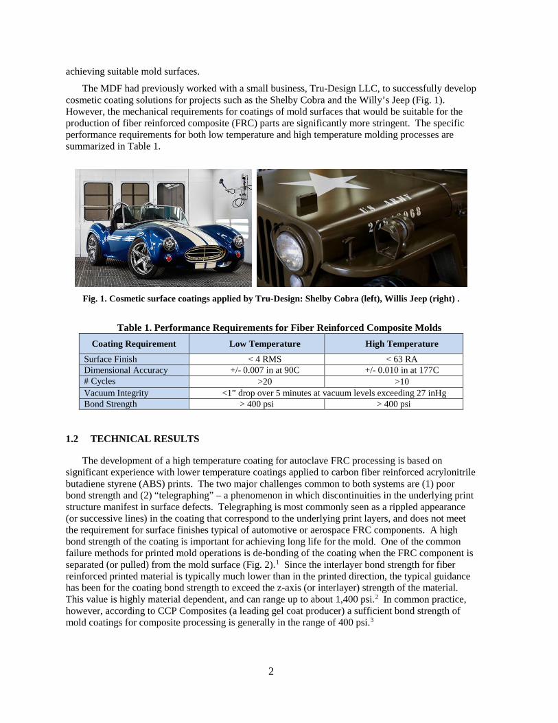
The MDF had previously worked with a small business, Tru-Design LLC, to successfully develop cosmetic coating solutions for projects such as the Shelby Cobra and the Willy’s Jeep (Fig. 1). However, the mechanical requirements for coatings of mold surfaces that would be suitable for the production of fiber reinforced composite (FRC) parts are significantly more stringent. The specific performance requirements for both low temperature and high temperature molding processes are summarized in Table 1.
Fig. 1. Cosmetic surface coatings applied by Tru-Design: Shelby Cobra (left), Willis Jeep (right) .
Table 1. Performance Requirements for Fiber Reinforced Composite Molds
Coating Requirement Low Temperature High Temperature
Surface Finish < 4 RMS < 63 RA Dimensional Accuracy +/- 0.007 in at 90C +/- 0.010 in at 177C # Cycles >20 >10 Vacuum Integrity <1” drop over 5 minutes at vacuum levels exceeding 27 inHg Bond Strength > 400 psi > 400 psi
1.2 TECHNICAL RESULTS
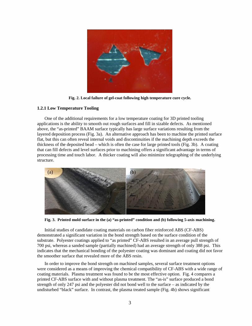
The development of a high temperature coating for autoclave FRC processing is based on significant experience with lower temperature coatings applied to carbon fiber reinforced acrylonitrile butadiene styrene (ABS) prints. The two major challenges common to both systems are (1) poor bond strength and (2) “telegraphing” – a phenomenon in which discontinuities in the underlying print structure manifest in surface defects. Telegraphing is most commonly seen as a rippled appearance (or successive lines) in the coating that correspond to the underlying print layers, and does not meet the requirement for surface finishes typical of automotive or aerospace FRC components. A high bond strength of the coating is important for achieving long life for the mold. One of the common failure methods for printed mold operations is de-bonding of the coating when the FRC component is separated (or pulled) from the mold surface (Fig. 2).1 Since the interlayer bond strength for fiber reinforced printed material is typically much lower than in the printed direction, the typical guidance has been for the coating bond strength to exceed the z-axis (or interlayer) strength of the material. This value is highly material dependent, and can range up to about 1,400 psi.2 In common practice, however, according to CCP Composites (a leading gel coat producer) a sufficient bond strength of mold coatings for composite processing is generally in the range of 400 psi.3
3
Fig. 2. Local failure of gel-coat following high temperature cure cycle.
1.2.1 Low Temperature Tooling
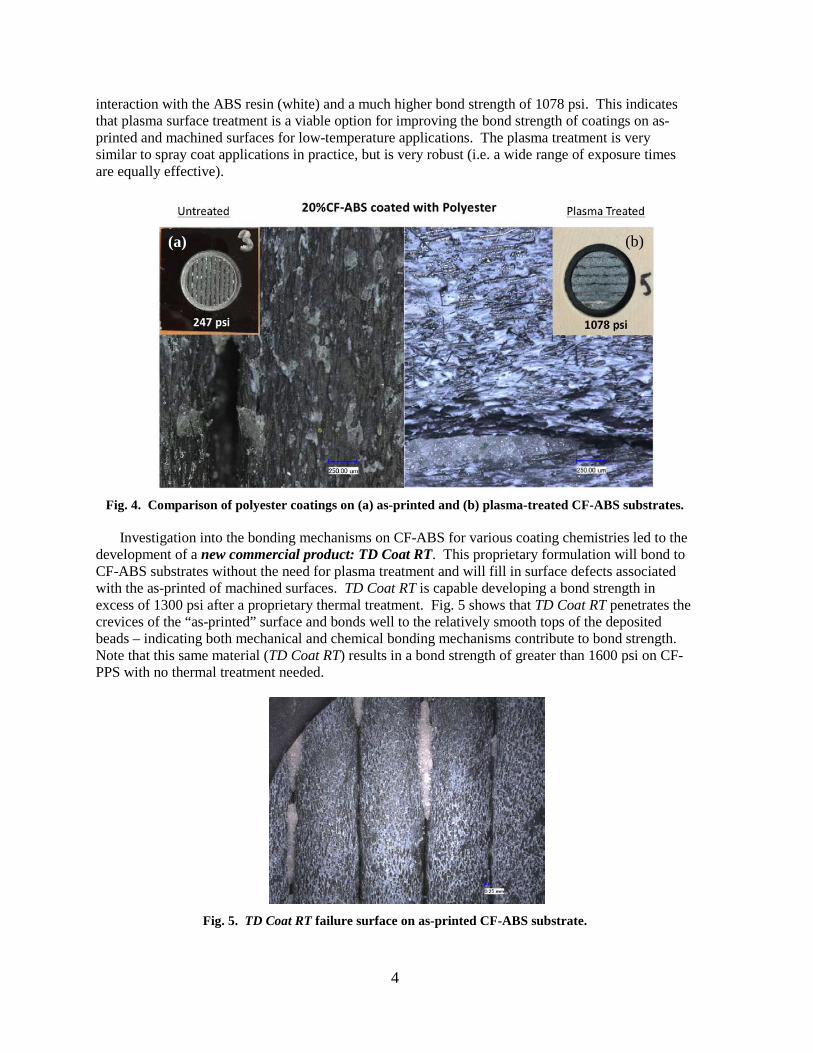
One of the additional requirements for a low temperature coating for 3D printed tooling applications is the ability to smooth out rough surfaces and fill in sizable defects. As mentioned above, the “as-printed” BAAM surface typically has large surface variations resulting from the layered deposition process (Fig. 3a). An alternative approach has been to machine the printed surface flat, but this can often reveal internal voids and discontinuities if the machining depth exceeds the thickness of the deposited bead – which is often the case for large printed tools (Fig. 3b). A coating that can fill defects and level surfaces prior to machining offers a significant advantage in terms of processing time and touch labor. A thicker coating will also minimize telegraphing of the underlying structure.
Fig. 3. Printed mold surface in the (a) “as-printed” condition and (b) following 5-axis machining. Initial studies of candidate coating materials on carbon fiber reinforced ABS (CF-ABS)
demonstrated a significant variation in the bond strength based on the surface condition of the substrate. Polyester coatings applied to “as printed” CF-ABS resulted in an average pull strength of 700 psi, whereas a sanded sample (partially machined) had an average strength of only 388 psi. This indicates that the mechanical bonding of the polyester coating was dominant and coating did not favor the smoother surface that revealed more of the ABS resin.
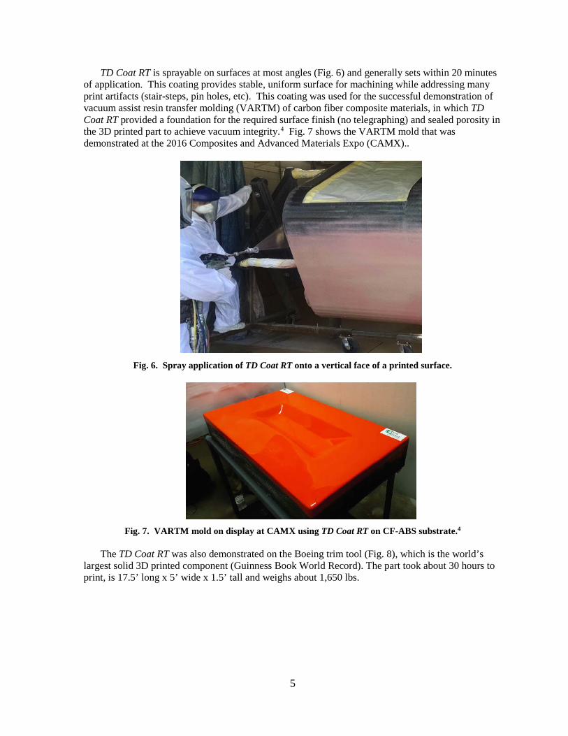
In order to improve the bond strength on machined samples, several surface treatment options were considered as a means of improving the chemical compatibility of CF-ABS with a wide range of coating materials. Plasma treatment was found to be the most effective option. Fig. 4 compares a printed CF-ABS surface with and without plasma treatment. The “as-is” surface produced a bond strength of only 247 psi and the polyester did not bond well to the surface – as indicated by the undisturbed “black” surface. In contrast, the plasma treated sample (Fig. 4b) shows significant
(a) (b)
4
interaction with the ABS resin (white) and a much higher bond strength of 1078 psi. This indicates that plasma surface treatment is a viable option for improving the bond strength of coatings on as-printed and machined surfaces for low-temperature applications. The plasma treatment is very similar to spray coat applications in practice, but is very robust (i.e. a wide range of exposure times are equally effective).
Fig. 4. Comparison of polyester coatings on (a) as-printed and (b) plasma-treated CF-ABS substrates.
Investigation into the bonding mechanisms on CF-ABS for various coating chemistries led to the
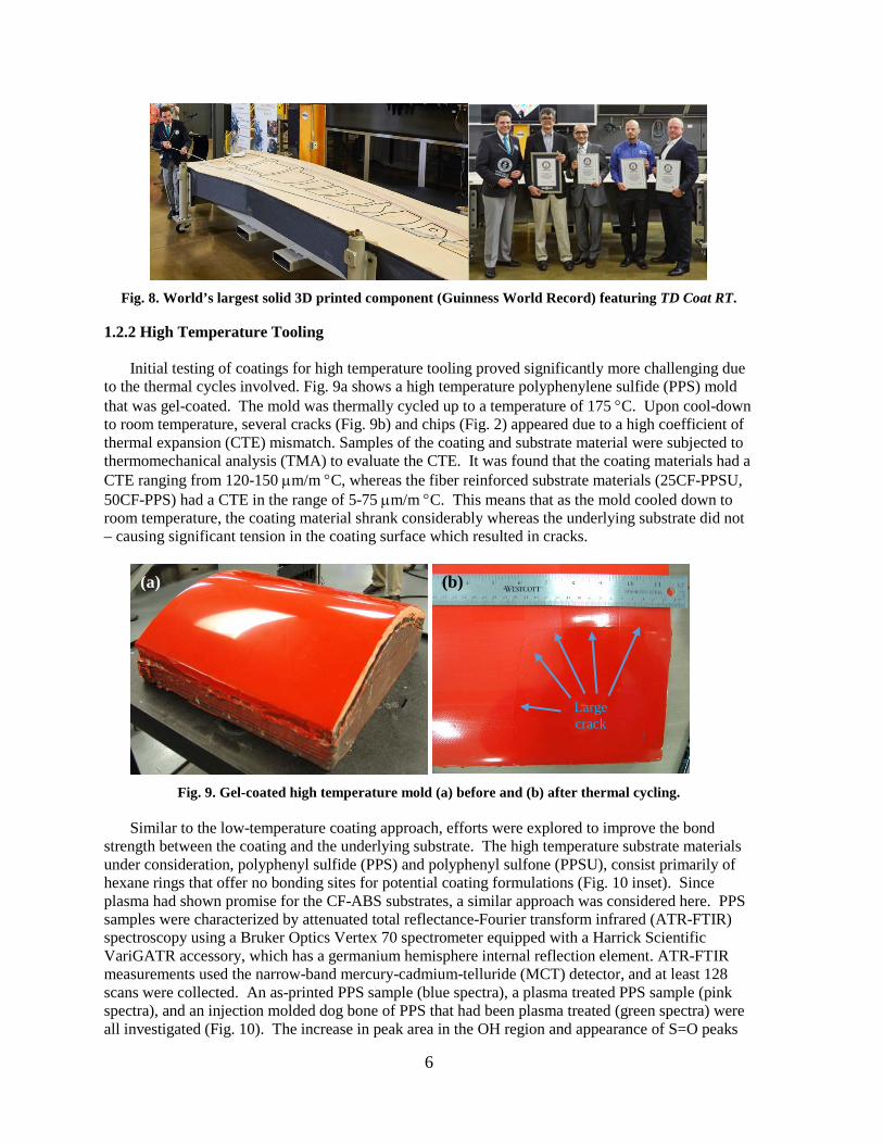
development of a new commercial product: TD Coat RT. This proprietary formulation will bond to CF-ABS substrates without the need for plasma treatment and will fill in surface defects associated with the as-printed of machined surfaces. TD Coat RT is capable developing a bond strength in excess of 1300 psi after a proprietary thermal treatment. Fig. 5 shows that TD Coat RT penetrates the crevices of the “as-printed” surface and bonds well to the relatively smooth tops of the deposited beads – indicating both mechanical and chemical bonding mechanisms contribute to bond strength. Note that this same material (TD Coat RT) results in a bond strength of greater than 1600 psi on CF-PPS with no thermal treatment needed.
Fig. 5. TD Coat RT failure surface on as-printed CF-ABS substrate.
(a) (b)
5
TD Coat RT is sprayable on surfaces at most angles (Fig. 6) and generally sets within 20 minutes of application. This coating provides stable, uniform surface for machining while addressing many print artifacts (stair-steps, pin holes, etc). This coating was used for the successful demonstration of vacuum assist resin transfer molding (VARTM) of carbon fiber composite materials, in which TD Coat RT provided a foundation for the required surface finish (no telegraphing) and sealed porosity in the 3D printed part to achieve vacuum integrity.4 Fig. 7 shows the VARTM mold that was demonstrated at the 2016 Composites and Advanced Materials Expo (CAMX)..
Fig. 6. Spray application of TD Coat RT onto a vertical face of a printed surface.
Fig. 7. VARTM mold on display at CAMX using TD Coat RT on CF-ABS substrate.4
The TD Coat RT was also demonstrated on the Boeing trim tool (Fig. 8), which is the world’s
largest solid 3D printed component (Guinness Book World Record). The part took about 30 hours to print, is 17.5’ long x 5’ wide x 1.5’ tall and weighs about 1,650 lbs.
6
Fig. 8. World’s largest solid 3D printed component (Guinness World Record) featuring TD Coat RT.
1.2.2 High Temperature Tooling
Initial testing of coatings for high temperature tooling proved significantly more challenging due to the thermal cycles involved. Fig. 9a shows a high temperature polyphenylene sulfide (PPS) mold that was gel-coated. The mold was thermally cycled up to a temperature of 175 °C. Upon cool-down to room temperature, several cracks (Fig. 9b) and chips (Fig. 2) appeared due to a high coefficient of thermal expansion (CTE) mismatch. Samples of the coating and substrate material were subjected to thermomechanical analysis (TMA) to evaluate the CTE. It was found that the coating materials had a CTE ranging from 120-150 µm/m °C, whereas the fiber reinforced substrate materials (25CF-PPSU, 50CF-PPS) had a CTE in the range of 5-75 µm/m °C. This means that as the mold cooled down to room temperature, the coating material shrank considerably whereas the underlying substrate did not – causing significant tension in the coating surface which resulted in cracks.
Fig. 9. Gel-coated high temperature mold (a) before and (b) after thermal cycling.
Similar to the low-temperature coating approach, efforts were explored to improve the bond
strength between the coating and the underlying substrate. The high temperature substrate materials under consideration, polyphenyl sulfide (PPS) and polyphenyl sulfone (PPSU), consist primarily of hexane rings that offer no bonding sites for potential coating formulations (Fig. 10 inset). Since plasma had shown promise for the CF-ABS substrates, a similar approach was considered here. PPS samples were characterized by attenuated total reflectance-Fourier transform infrared (ATR-FTIR) spectroscopy using a Bruker Optics Vertex 70 spectrometer equipped with a Harrick Scientific VariGATR accessory, which has a germanium hemisphere internal reflection element. ATR-FTIR measurements used the narrow-band mercury-cadmium-telluride (MCT) detector, and at least 128 scans were collected. An as-printed PPS sample (blue spectra), a plasma treated PPS sample (pink spectra), and an injection molded dog bone of PPS that had been plasma treated (green spectra) were all investigated (Fig. 10). The increase in peak area in the OH region and appearance of S=O peaks
Large crack
(a) (b)
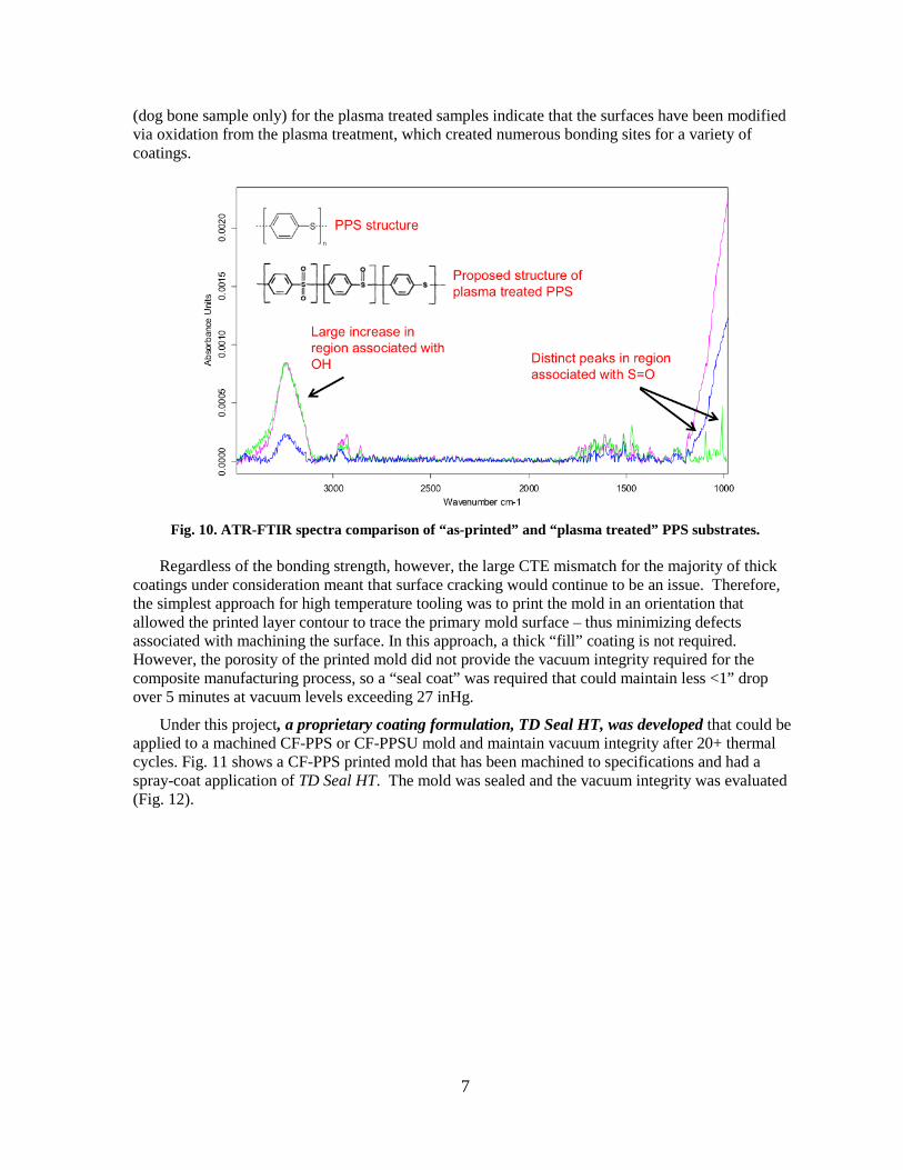
7
(dog bone sample only) for the plasma treated samples indicate that the surfaces have been modified via oxidation from the plasma treatment, which created numerous bonding sites for a variety of coatings.
Fig. 10. ATR-FTIR spectra comparison of “as-printed” and “plasma treated” PPS substrates.
Regardless of the bonding strength, however, the large CTE mismatch for the majority of thick
coatings under consideration meant that surface cracking would continue to be an issue. Therefore, the simplest approach for high temperature tooling was to print the mold in an orientation that allowed the printed layer contour to trace the primary mold surface – thus minimizing defects associated with machining the surface. In this approach, a thick “fill” coating is not required. However, the porosity of the printed mold did not provide the vacuum integrity required for the composite manufacturing process, so a “seal coat” was required that could maintain less <1” drop over 5 minutes at vacuum levels exceeding 27 inHg.
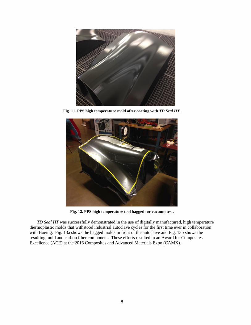
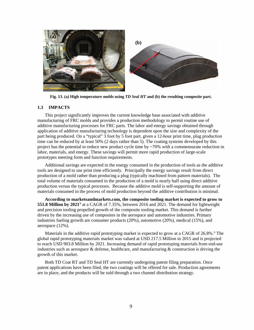
Under this project, a proprietary coating formulation, TD Seal HT, was developed that could be applied to a machined CF-PPS or CF-PPSU mold and maintain vacuum integrity after 20+ thermal cycles. Fig. 11 shows a CF-PPS printed mold that has been machined to specifications and had a spray-coat application of TD Seal HT. The mold was sealed and the vacuum integrity was evaluated (Fig. 12).
8
Fig. 11. PPS high temperature mold after coating with TD Seal HT.
Fig. 12. PPS high temperature tool bagged for vacuum test.
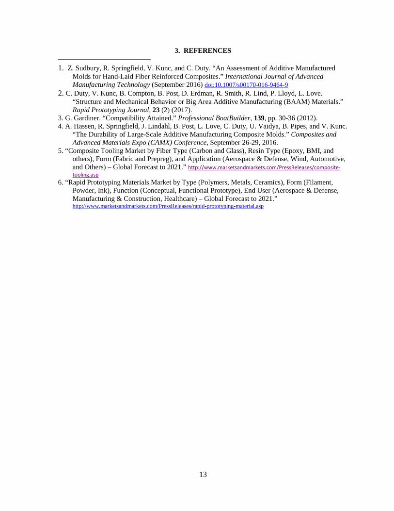
TD Seal HT was successfully demonstrated in the use of digitally manufactured, high temperature
thermoplastic molds that withstood industrial autoclave cycles for the first time ever in collaboration with Boeing. Fig. 13a shows the bagged molds in front of the autoclave and Fig. 13b shows the resulting mold and carbon fiber component. These efforts resulted in an Award for Composites Excellence (ACE) at the 2016 Composites and Advanced Materials Expo (CAMX).
9
Fig. 13. (a) High temperature molds using TD Seal HT and (b) the resulting composite part.
1.3 IMPACTS
This project significantly improves the current knowledge base associated with additive manufacturing of FRC molds and provides a production methodology to permit routine use of additive manufacturing processes for FRC parts. The labor and energy savings obtained through application of additive manufacturing technology is dependent upon the size and complexity of the part being produced. On a “typical” 3 foot by 5 foot part, given a 12-hour print time, plug production time can be reduced by at least 50% (2 days rather than 5). The coating systems developed by this project has the potential to reduce new product cycle time by ~70% with a commensurate reduction in labor, materials, and energy. These savings will permit more rapid production of large-scale prototypes meeting form and function requirements.
Additional savings are expected in the energy consumed in the production of tools as the additive tools are designed to use print time efficiently. Principally the energy savings result from direct production of a mold rather than producing a plug (typically machined from pattern materials). The total volume of materials consumed in the production of a mold is nearly half using direct additive production versus the typical processes. Because the additive mold is self-supporting the amount of materials consumed in the process of mold production beyond the additive contribution is minimal.
According to marketsandmarkets.com, the composite tooling market is expected to grow to 551.8 Million by 20215 at a CAGR of 7.35%, between 2016 and 2021. The demand for lightweight and precision tooling propelled growth of the composite tooling market. This demand is further driven by the increasing use of composites in the aerospace and automotive industries. Primary industries fueling growth are consumer products (20%), automotive (20%), medical (15%), and aerospace (12%).
Materials in the additive rapid prototyping market is expected to grow at a CAGR of 26.8%.6 The global rapid prototyping materials market was valued at USD 217.5 Million in 2015 and is projected to reach USD 903.8 Million by 2021. Increasing demand of rapid prototyping materials from end-use industries such as aerospace & defense, healthcare, and manufacturing & construction is driving the growth of this market.
Both TD Coat RT and TD Seal HT are currently undergoing patent filing preparation. Once patent applications have been filed, the two coatings will be offered for sale. Production agreements are in place, and the products will be sold through a two channel distribution strategy.
(a) (b)

10
1.4 CONCLUSIONS During this Phase II Technical Collaboration, ORNL worked with TruDesign, LLC to develop
viable coating solutions to enable the use of large scale 3D printing for both low-temperature and high-temperature composite molds. The bonding mechanisms of various coatings on fiber reinforced printed substrates was explored and suitable surface treatments were found to increase the bond strength by a factor of 4. This project also resulted in the development of two separate commercial products that are patent-pending: TD Coat RT and TD Seal HT. Using these products, the research team successfully demonstrated the use of printed molds for autoclave processing for the first time.

11
2. PARTNER BACKGROUND
Tru-Design, LLC is creating, developing and manufacturing products using alternative materials,
such as carbon fiber composites that will aid in conserving energy and natural resources for the benefit of our economy. Tru-Design is focused on engineering, prototyping and low-volume production of composite and carbon fiber products. The company’s years of experience developing composite and carbon fiber manufacturing processes, position Tru-Design for manufacture and sales into several markets, but principally transportation markets.

12
13
3. REFERENCES
1. Z. Sudbury, R. Springfield, V. Kunc, and C. Duty. “An Assessment of Additive Manufactured Molds for Hand-Laid Fiber Reinforced Composites.” International Journal of Advanced Manufacturing Technology (September 2016) doi:10.1007/s00170-016-9464-9
2. C. Duty, V. Kunc, B. Compton, B. Post, D. Erdman, R. Smith, R. Lind, P. Lloyd, L. Love. “Structure and Mechanical Behavior or Big Area Additive Manufacturing (BAAM) Materials.” Rapid Prototyping Journal, 23 (2) (2017).
3. G. Gardiner. “Compatibility Attained.” Professional BoatBuilder, 139, pp. 30-36 (2012). 4. A. Hassen, R. Springfield, J. Lindahl, B. Post, L. Love, C. Duty, U. Vaidya, B. Pipes, and V. Kunc.
“The Durability of Large-Scale Additive Manufacturing Composite Molds.” Composites and Advanced Materials Expo (CAMX) Conference, September 26-29, 2016.
5. “Composite Tooling Market by Fiber Type (Carbon and Glass), Resin Type (Epoxy, BMI, and others), Form (Fabric and Prepreg), and Application (Aerospace & Defense, Wind, Automotive, and Others) – Global Forecast to 2021.” http://www.marketsandmarkets.com/PressReleases/composite-tooling.asp
6. “Rapid Prototyping Materials Market by Type (Polymers, Metals, Ceramics), Form (Filament, Powder, Ink), Function (Conceptual, Functional Prototype), End User (Aerospace & Defense, Manufacturing & Construction, Healthcare) – Global Forecast to 2021.” http://www.marketsandmarkets.com/PressReleases/rapid-prototyping-material.asp