Embed Size (px)
Citation preview
September 2002
NASA/TM-2002-211926
Evaluation of an Aircraft Concept WithOver-Wing, Hydrogen-Fueled Engines forReduced Noise and Emissions
Mark D. Guynn and Erik D. OlsonLangley Research Center, Hampton, Virginia

The NASA STI Program Office ... in Profile
Since its founding, NASA has been dedicatedto the advancement of aeronautics and spacescience. The NASA Scientific and TechnicalInformation (STI) Program Office plays a keypart in helping NASA maintain this importantrole.
The NASA STI Program Office is operated byLangley Research Center, the lead center forNASA’s scientific and technical information.The NASA STI Program Office providesaccess to the NASA STI Database, the largestcollection of aeronautical and space scienceSTI in the world. The Program Office is alsoNASA’s institutional mechanism fordisseminating the results of its research anddevelopment activities. These results arepublished by NASA in the NASA STI ReportSeries, which includes the following reporttypes:
• TECHNICAL PUBLICATION. Reports
of completed research or a majorsignificant phase of research thatpresent the results of NASA programsand include extensive data or theoreticalanalysis. Includes compilations ofsignificant scientific and technical dataand information deemed to be ofcontinuing reference value. NASAcounterpart of peer-reviewed formalprofessional papers, but having lessstringent limitations on manuscriptlength and extent of graphicpresentations.
• TECHNICAL MEMORANDUM.
Scientific and technical findings that arepreliminary or of specialized interest,e.g., quick release reports, workingpapers, and bibliographies that containminimal annotation. Does not containextensive analysis.
• CONTRACTOR REPORT. Scientific and
technical findings by NASA-sponsoredcontractors and grantees.
• CONFERENCE PUBLICATION.Collected papers from scientific andtechnical conferences, symposia,seminars, or other meetings sponsoredor co-sponsored by NASA.
• SPECIAL PUBLICATION. Scientific,
technical, or historical information fromNASA programs, projects, and missions,often concerned with subjects havingsubstantial public interest.
• TECHNICAL TRANSLATION. English-
language translations of foreignscientific and technical materialpertinent to NASA’s mission.
Specialized services that complement theSTI Program Office’s diverse offeringsinclude creating custom thesauri, buildingcustomized databases, organizing andpublishing research results ... evenproviding videos.
For more information about the NASA STIProgram Office, see the following:
• Access the NASA STI Program HomePage at http://www.sti.nasa.gov
• E-mail your question via the Internet to
[email protected] • Fax your question to the NASA STI
Help Desk at (301) 621-0134 • Phone the NASA STI Help Desk at (301)
621-0390 • Write to:
NASA STI Help Desk NASA Center for AeroSpace Information 7121 Standard Drive Hanover, MD 21076-1320
National Aeronautics andSpace Administration
Langley Research CenterHampton, Virginia 23681-2199
September 2002
NASA/TM-2002-211926
Evaluation of an Aircraft Concept WithOver-Wing, Hydrogen-Fueled Engines forReduced Noise and Emissions
Mark D. Guynn and Erik D. OlsonLangley Research Center, Hampton, Virginia

Available from:
NASA Center for AeroSpace Information (CASI) National Technical Information Service (NTIS)7121 Standard Drive 5285 Port Royal RoadHanover, MD 21076-1320 Springfield, VA 22161-2171(301) 621-0390 (703) 605-6000
AcknowledgmentsThe authors gratefully acknowledge the contributions made to the study described in this report by personnel in thePropulsion Systems Analysis Office at NASA Glenn Research Center; in particular Tom Lavelle, David Koci, and JeffBerton.
1
Executive Summary
Throughout the world the environmental impacts of all industries, including aviation, are under scrutiny.It is widely believed that environmental issues will be an ever present and growing concern for aviation.Aviation faces a particularly difficult challenge due to its projected rapid growth (faster than GrossDomestic Product and most other industries) and the demanding performance requirements associatedwith air transportation. In some industries technology is already available to greatly reduceenvironmental impacts, the issue is simply the cost of implementation. In the case of aviation, however,there are no simple solutions. On the other hand, a sustainable air transportation system, which is able tomeet society’s demand for minimal environmental impact, is an important factor in future economicgrowth.
Of the various environmental impacts of aviation, aircraft noise and emissions are at the forefront.Because of the importance of these issues to the future of aviation, a “Quiet Green Transport” (QGT)study was chosen as one of the initial studies conducted in NASA’s Revolutionary Aerospace SystemsConcepts (RASC) Program. The objective of the QGT study is to develop and evaluate commercialtransport aircraft concepts that significantly reduce or eliminate aircraft noise and emissions. Modelingand evaluation of the first concept considered in the study, Concept A, is described in this report.Concept A is a strut-braced wing configuration with over-wing, ultra-high bypass ratio, hydrogen fueledturbofan engines. Projected benefits of Concept A include complete elimination of all aircraft emissionsexcept NOX and water vapor and a 53% reduction, relative to today’s equivalent aircraft, in the areaexposed to noise levels of 55dB and greater during takeoff and landing operations. NOX emitted by theaircraft during takeoff and landing operations is also reduced by 18%. With near term technologyassumptions, the total amounts of NOX and water vapor emitted by Concept A over the entire flight arehigher than today’s conventional aircraft. These penalties can be addressed through future technologyadvances. In addition, Concept A was designed to cruise at a reduced altitude to provide the potential toeliminate the formation of persistent contrails, minimizing the impact of its water vapor emissions.
In addition to developing concepts, another objective of RASC studies is to identify the technologyadvances necessary to bring the concepts to reality. The most revolutionary technology advancesrequired for Concept A are related not to the aircraft itself but to the liquid hydrogen (LH2) fuel used. Inorder for Concept A to be practical, large scale, economical, environmentally friendly production of LH2
is needed. With current technology, environmentally friendly production methods are only viable on asmall scale and/or are very expensive. Widespread availability of LH2 is necessary for Concept A tobecome a reality. Furthermore, if the production of LH2 is not “environmentally friendly,” theenvironmental benefits of Concept A are diluted. The technology issues associated with hydrogen fuelare currently being addressed in many research projects, including those directed by the Department ofEnergy Hydrogen Program.
Since Concept A is revolutionary, representing a fundamental change from current aircraft, there are anumber of challenges associated with the design which would require engineering and development tosolve. However, the technology advances needed to build such an aircraft could probably be available inthe near term. Even so, noise and emission benefits would be greatly enhanced through application ofadvanced technologies in a few key areas. The NOX emissions of Concept A could be greatly reduced byutilization of advanced combustors. NASA and others are currently developing combustor conceptswhich offer the potential for significant NOX reduction. H2O and NOX emissions are both sensitive toadvances in the areas of aircraft drag, engine fuel efficiency, and airframe structural weight. The overallnoise characteristics of Concept A were found to be mainly sensitive to airframe noise. Advancedtechnologies for airframe noise reduction could significantly augment the noise benefits of Concept A.

2

3
Contents
Executive Summary.................................................................................................................................1
Contents ..................................................................................................................................................3
1. Introduction .........................................................................................................................................5
1.1 Aviation and the Environment – Current Outlook ..........................................................................5
1.2 Aviation and the Environment - Possible Future Scenarios.............................................................6
2. Study Overview ...................................................................................................................................8
3. General Concept Description ...............................................................................................................9
4. Design Mission Requirements..............................................................................................................9
5. Modeling and Analysis Methodologies ..............................................................................................10
5.1 Aircraft Performance Analysis.....................................................................................................10
5.2 Noise Analysis ............................................................................................................................11
6. Concept Evaluation Results................................................................................................................13
6.1 Performance and Sizing ...............................................................................................................13
6.2 Emissions Characteristics ............................................................................................................14
6.3 Noise Characteristics ...................................................................................................................15
7. Technology Requirements..................................................................................................................16
8. Technology Sensitivities ....................................................................................................................18
9. Concluding Remarks..........................................................................................................................19
10. References…………………………………………………………………….…….…..………..……21
Tables……………………………………………….……………………..……………………..…..……23
Figures………………………………………….………………………………………………………….26

4

5
1. Introduction
1.1 Aviation and the Environment – Current Outlook
Many industries today have an increased awareness of the environmental impact of products they produceand services they provide. In some cases this is driven by existing or proposed government regulations,while in other cases it is driven by a desire to be seen as “green” by consumers. The idea of using“green” as a selling point to consumers is even stronger in other areas of the world than in the UnitedStates. Growing attention to environmental issues is likely due to the increased understanding of howfuture public health and welfare is being adversely impacted by today’s activities. The trend toward“green” has not been overlooked by the aviation industry. For example, on Boeing’s commercial airplanewebsite catch phases like, “Concern for the environment…at Boeing it comes naturally” are foundthroughout the promotional literature (ref. 1). The Boeing 767 family of aircraft is called, “the rightchoice for the environment” because of lower noise and emissions compared to the similarly sized AirbusA330 (ref. 2). Airbus states that its new A380 design, “…brings new standards of comfort, bettereconomics, in an aircraft that is more environmentally responsible…” and refers to the A380 as a “newgreen giant”(ref. 3). In addition to aircraft manufacturers, the service providers (i.e. airlines) have alsobegun to address environmental issues. Some airlines have formal environmental goals or objectives andpublicize the ways in which they have reduced the environmental impact of their operations (refs. 4,5,6).The Star Alliance, a global alliance of 15 air carriers including U.S. carrier United Airlines, issued anEnvironmental Commitment Statement in May 1999. One of the commitments is, “we will strive todevelop and use technology that is environmentally sound and we will promote enhanced environmentalstandards in our purchasing of new aircraft, equipment, and facilities” (ref. 7). Lufthansa, a member ofthe Star Alliance, has a corporate goal to, “Reduce specific fuel consumption by 30 percent from 1991 to2008, and by 35 percent by 2012”(ref. 5).
Despite the greater attention being paid to environmental issues by the aviation industry, theenvironmental challenges faced by the industry are significant. These challenges stem from a rapidgrowth in the demand for air travel and a “greening” of other industries, including other modes oftransportation. Although aviation’s impact on the environment can be fairly significant near airports, inglobal terms aviation’s current contribution to environmental problems is relatively small. However, thenegative environmental impacts from aviation are growing. Unconstrained the demand for passenger airtravel is projected to nearly triple over the next 25 years. The growth in air cargo is projected to be evenfaster, increasing 4.5 times over the same period (ref. 8). At the same time, other industries will bereducing their relative environmental impact in response to stricter regulations and the availability of new,revolutionary technologies. Figure 1, based on data in reference 9, illustrates the projected increase in therelative contribution of aircraft to regional NOX emissions. An upward trend is also predicted for therelative contribution of aircraft to global warming as shown in figure 2, from reference 10. Despite therelatively small current contributions, some environmental groups have been calling attention to theenvironmental impacts of aviation for several years (e.g., refs. 11 and 12). As the contribution of aviationto environmental problems grows in the future, the calls for action will likely become louder.
The capacity issues expected to face aviation in the future are also closely tied to the environmentalissues. Aircraft noise already constrains air transportation through curfews, noise budgets and limits, andslot restrictions. One of the barriers to construction of new airports and/or expansion of operations atexisting airports is the negative environmental impact on surrounding communities. According to theNational Science and Technology Council (NSTC) report, Goals for a National Partnership inAeronautics Research and Technology (ref. 13), “Environmental issues are likely to impose thefundamental limitation on air transportation growth in the 21st century.” Environmental concerns could
6
constrain growth of the air transportation system either directly, such as through noise and emissionlimits, or indirectly through opposition to new airports on the basis of environmental concerns. If the airtransportation system is not able to grow at a rate sufficient to meet demand, there will be an increase inair transportation costs and negative economic impacts.
The environmental impact of aviation is a broad topic involving many aspects, including, but not limitedto: aircraft, airports, ground support equipment, and operational procedures. A complete assessment ofjust the aircraft related aspects would have to include a number of factors such as the manufacturingprocess and the ability to recycle aircraft materials, in addition to the traditional concerns of aircraftproduced noise and emissions. Although there are numerous facets to an environmentally friendlyaircraft, the present study is focused only on aircraft noise and emissions characteristics. Reducing noiseand reducing emissions are two of the five strategic objectives under the NASA Aerospace TechnologyEnterprise “Revolutionize Aviation” goal (ref. 14). The NSTC report, National Research andDevelopment Plan for Aviation Safety, Security, Efficiency, and Environmental Compatibility (ref. 15)states, “…developing technology for reducing noise and emissions are essential to sustaining aviation’svitality…”
Over the past fifty years, aircraft and engine manufactures have made great strides in reducing noise andemissions (though usually not motivated strictly by concern for the environment.) In fact, Boeingpresents a perspective that aircraft of today are quieter and cleaner than other forms of transportation (ref.1). However, the rate of aircraft noise and emission reductions from evolutionary technologyimprovements is slowing. For example, figure 3 from reference 10 shows the reduction in specific fuelconsumption since the introduction of the jet transport. Clearly the rate of improvement in fuel efficiencyhas slowed drastically in the past two decades. A similar trend also exists for aircraft noise levels. Therate of noise and emissions reduction from evolutionary improvements in airframe and engine technologycannot keep pace with the projected growth in air travel and a steady rise in the negative environmentalimpacts of aviation will result. In addition, the relative size of aviation’s impacts will grow as otherindustries move beyond evolutionary technology improvements to fundamental changes (e.g. fuel cellpowered cars). To reverse these trends, revolutionary approaches to aircraft noise and emissions reductionare needed.
1.2 Aviation and the Environment - Possible Future Scenarios
When developing and evaluating advanced aircraft concepts which could enter the market decades in thefuture, it is not sufficient to only consider the current market environment. It is also necessary to considerpossible future environments that will dictate the desired design attributes. It is impossible to predictwhat the world will be like many years in the future, but based on today’s environment plausible futurescan be extrapolated.
Because of population and economic growth, the demand for air travel is projected to continue growing.Certainly a number of scenarios could be postulated in which the demand for air travel stagnates or evendeclines. However, if air travel grows as predicted, the environmental issues noted above will continue tobe a concern.
It is reasonable to expect that noise will continue to be an important aspect of future aircraft. Alreadyaircraft noise is an issue that daily affects how airlines operate. Because of aircraft noise regulationsimposed by the International Civil Aviation Organization (ICAO) and the Federal AviationAdministration (FAA), and noise related restrictions and fees imposed by individual airports, there iscurrently a fairly strong economic incentive for airlines to consider noise characteristics in the purchase of
7
aircraft. Quieter aircraft tend to provide the airline with more flexibility in utilization, as well as a hedgeagainst possible future reductions in regulated noise limits during the ~30 year lifetime of the aircraft. Asimportant as noise is today, it will probably be even more of an issue in the future. As the number ofoperations grows, the noise generated by each individual aircraft will have to decrease to avoid growth inthe area around the airport subjected to excessive total noise levels. In addition, it is likely that as thecapacity limits of the current hub-and-spoke airline route structure are reached, a transition to more point-to-point service will occur. In this case, much of the growth in operations will occur at airports whichcurrently have low traffic and little noise. Moving to a more distributed air transportation system wouldmake aircraft noise an issue for even a greater segment of the population than it is today. Therefore,strong incentives for aircraft noise reduction will likely continue to exist in the future.
Future scenarios concerning the importance of aircraft emissions are somewhat more speculative thanthose for noise. The only aircraft emissions currently regulated are landing-takeoff cycle (LTO)emissions of NOX, CO, unburned hydrocarbons, and smoke. Although there are some airports whichcurrently have fees based on aircraft LTO emission characteristics, the incentives for buying loweremission aircraft appear to be much weaker than those associated with noise. For example, only ahandful of airlines are buying special low NOX engines available for some aircraft because of the extracosts compared to the standard, higher NOX engines. There is a strong economic incentive for buyingfuel-efficient aircraft, which can have an indirect beneficial impact on emissions as well. Aircraft whichare more fuel-efficient tend to have lower emissions (although not always the case for NOX emissions).Since fuel cost is a significant portion of airline operating cost, more fuel-efficient aircraft are desirable.The desire for reduced fuel cost has led to continual improvement in aircraft efficiency and reduction inmost emissions. But, in today’s environment, there is no incentive for using an alternate fuel that resultsin even lower emissions if it cost more than normal jet fuel.
The differences in the current perspectives on aircraft noise and emissions are due in part to fundamentaldifferences in the two issues. The impacts of aircraft emissions on human health and well-being are muchmore indirect and uncertain than those of aircraft noise. Aircraft noise has a direct and immediate affecton the “quality of life” of those exposed to it. The effects of aircraft emissions tend to be more long term,and in most cases materialize as part of a larger problem. For example, a “silent aircraft” would probablysolve the airport noise issue. However, “emissionless aircraft” would not solve the air quality problemsaround airports or the global climate change problem. Furthermore, the importance of issues such asglobal climate change is still somewhat uncertain and the subject of much debate. Despite the currentuncertainties, the visibility of issues related to aircraft emissions, and anthropogenic emissions in general,has been growing. It is likely that this trend will continue and as a result in the future there could beeconomic incentives for aircraft with significant emissions reduction or elimination. These incentivescould come in a number of different forms such as emission taxes, emission permit trading, emissioncaps, etc., or even consumer demand for low emission transportation.
If “green” is important for aviation, it will be for other industries as well. Substantial research efforts arein place today to develop the technologies needed to move towards an economy based on “greener”energy sources. A future “hydrogen economy,” with hydrogen produced by renewable energy sourcesand used as an energy carrier, is the goal of much of that research. A transition to alternate fuels such ashydrogen is not something that the aviation industry would likely do alone, but as part of a shift towardsthese fuels by many industries. Currently, the incentive for using alternate fuels is much stronger in otherareas than in aviation, as evidenced by the large investment in hydrogen fuel technologies for groundvehicles. For this reason, and because of the greater challenges faced in aircraft design, it is anticipatedthat aviation will follow behind other sectors in making any fuel transition. When developing andevaluating the aircraft concept described in this report, it was assumed that a transition to alternate fuels

8
by many industries would occur in the future, making alternate fuels available to aviation as well. Basedon the current direction of research in the Department of Energy (DOE) and Department ofTransportation (DOT), hydrogen appears to be a likely alternate fuel candidate.
2. Study Overview
The work presented in this report was conducted as part of the “Quiet Green Transport” study of NASA’sRevolutionary Aerospace Systems Concepts (RASC) Program. The RASC vision is to develop andanalyze revolutionary concepts (considering a 25-50 year time horizon) that address strategic objectivesof the NASA Enterprises and to identify the enabling advanced technology requirements for the concepts.The RASC Quiet Green Transport study addresses the aircraft noise and emission reduction goals ofNASA’s Aerospace Technology Enterprise. The Quiet Green Transport (QGT) study actually evolvedfrom a number of recent NASA studies which investigated advanced concepts for reducing noise andemissions. Past studies were generally focused on advanced concepts for either noise or emissions, butdid not combine these concepts into one aircraft configuration as done in the QGT study. However, manyof the ideas, concepts, assumptions, and knowledge from these previous studies were used as initial inputfor the QGT study. In addition, related studies being performed concurrently with the QGT study wereused as a continuing source of input. In 1998-1999 a series of high-level studies was performed jointly byNASA Langley Research Center (LaRC) and NASA Glenn Research Center (GRC) which exploredaircraft with unconventional propulsion concepts for the reduction or elimination of aircraft emissions.The types of propulsion systems studied included: methane fueled gas turbine propulsion, hydrogenfueled gas turbine propulsion, hydrogen fuel cell/electric propulsion, lithium-air fuel cell/electricpropulsion, and nuclear propulsion. Hydrogen fueled gas turbine based propulsion was investigatedfurther in concept studies conducted in 2000 as part of the GRC Zero CO2 Emissions Technology (ZCET)project. Since 1999, MSE Technology Applications, Inc. has been performing a study funded by LaRC toinvestigate the future possibilities for a totally emissionless transport aircraft. This study has covered abroad range of possible technologies, including breakthrough concepts which challenge traditional viewsof propulsion and energy systems. Advanced concepts for noise reduction that have been recentlyinvestigated include over-wing engine placement and scarf engine inlets. The available knowledge basefor noise and emission reduction concepts is much broader than the recent studies mentioned above andincludes numerous past reports. Where appropriate, information from these reports was also used as aresource for the current effort.
The ultimate vision for a Quiet Green Transport is the ability to move people (and goods) by air withoutharming the Earth or degrading the quality of life of its residents. In the context of the QGT study this isinterpreted to mean that objectionable aircraft noise is contained within the airport boundary and theaircraft does not emit any substance where it has a significant environmental impact. The objectives ofthe QGT study are to define revolutionary aircraft concepts that are aimed toward achieving this visionand to identify the technology advances necessary to make those concepts feasible. Note that while allthe concepts investigated in the study are focused on the above vision, not all of the concepts arenecessarily capable of fully achieving it. Fully achieving the vision is a very demanding goal which mayrequire technology advances that are unrealistic even in the 25-50 year time horizon considered for RASCstudies. Even though “green” technologies are beginning to find application in a number of other areas,and are projected to significantly penetrate many markets in the near future, the design requirements foraircraft application are much more demanding.
A set of three aircraft concepts, developed from “brainstorming” ideas to eliminate aircraft noise andemission sources (or significantly reduce their impacts), were selected for evaluation in the QGT study.The first concept defined and analyzed, referred to as Concept A, is the focus of this report. This is the
9
“lowest risk/lowest benefit” concept of the three selected and integrates noise and emission reductionfeatures which are lower risk relative to other proposed ideas.
3. General Concept Description
The general arrangement of Quiet Green Transport Concept A is illustrated in figure 4. The conceptfeatures “ultra-high” bypass ratio, hydrogen (H2) fueled turbofan engines with scarf inlets placed above astrut-braced wing. The hydrogen fuel is stored as a cryogenic liquid (LH2) in fuselage tanks. Using H2
turbofan engines eliminates all aircraft emissions except H2O and NOX. The over-wing placement andscarf inlets provide shielding of the engine noise relative to the ground. A strut-braced wingconfiguration was selected for its increased aerodynamic and structural efficiency relative to aconventional wing arrangement. Concept A also includes two operational approaches to reducing theimpact of the noise and emissions generated. To reduce approach noise, the approach angle is increasedfrom today’s 3° standard approach to 6°. At a given distance from the runway, this increases the aircraftaltitude and reduces the noise propagated to the ground. The second operational measure is providing areduced altitude cruise capability. The optimum cruise altitude for subsonic jet aircraft is usually in theupper troposphere. However, the ambient conditions at this altitude are often conducive to the formationof persistent contrails, which are triggered by aircraft H2O emissions and are believed to have asignificant environmental impact (ref. 10). It is presently unclear exactly how contrail formation andcontrail properties for a H2 aircraft would compare to today’s kerosene fueled aircraft. But, by providingcruise capability at reduced altitude, where contrail formation is unlikely, it should be possible to fly acruise profile that avoids the formation of persistent contrails.
4. Design Mission Requirements
The basic design mission requirements selected for the QGT study are a payload capability of 225passengers (in a 3-class seating arrangement) plus baggage and a range capability of 3500 nmi with fullpayload. A 225 passenger vehicle was chosen based on the projected future fleet mix shown in figure 5.Small aircraft tend to have a large number of operations but fly relatively few seat-miles. Large aircrafttend to have relatively few operations, but represent the majority of the seat-miles flown. Airport noiseand local air quality issues are related primarily to the number of operations, while global atmosphericissues are related primarily to the total number of seat-miles flown. A fleet of quiet, green aircraft ofvarious sizes would obviously be needed to significantly reduce aviation’s environmental impacts.However, since the scope of the current study was limited to one vehicle class, a “mid-size” class whichrepresents both a significant portion of projected airport operations and of total seat-miles flown wasselected. The chosen passenger capacity is roughly equivalent to a Boeing 767-300 class aircraft whilethe range capability is lower. The maximum range of a Boeing 767-300ER is slightly over 6000 nmi, butthe majority of routes flown by aircraft in the 225 passenger class do not require this range capability. Infact, in 1999 the average route distance flown by 767-300s was only 1424 nmi (ref. 16). Previous studiesof “zero emission” aircraft have indicated that the feasibility of some concepts is very sensitive to therange requirement. With a 6000 nmi range requirement these concepts would be penalized by a rangecapability that is not often needed or used. A range capability of 3500 nmi was deemed suitable tocomplete the majority of flights typical for this class of aircraft and was selected as the design rangerequirement. The design mission profile is illustrated in figure 6. In addition to the payload and rangerequirements, the concept must satisfy constraints on landing and takeoff field length, approach speed,takeoff and missed approach climb gradients, and rate-of-climb capability at top of climb.
10
5. Modeling and Analysis Methodologies
There is an inherent difficulty in the study of unconventional concepts in that most analysis tools arebased on and geared to existing design paradigms. Furthermore, the details of the concepts are generallynot well defined. The analysis for this study, therefore, was performed at a fairly high, conceptual level.In some cases significant tool development was still necessary to adequately model elements of theconcept. In other cases, simplifying assumptions were made to allow the use of existing tools.
5.1 Aircraft Performance Analysis
Aircraft performance and sizing analysis was performed with the LaRC Flight Optimization System(FLOPS) computer code. (Note: a specially modified version of FLOPS was developed to automatesizing of fuselage fuel tanks and fuselage length.) An existing FLOPS model for a current technology,conventional baseline aircraft was used as a starting point for Concept A to ensure consistency in themodeling. The major changes to the conventional aircraft model necessary to model Concept A were:changing to a strut-braced wing, changing to liquid hydrogen (LH2) fuel, incorporating the new LH2
engine, and adding reduced altitude cruise capability. Concept A was initially modeled using current tonear term technology assumptions, establishing a technology baseline from which the impact of possiblefuture technology advances could be assessed.
The FLOPS code has some limited capability to model strut-braced wings. A “wing strut-bracing factor”is provided in the structural weight equations to represent the structural weight reduction realized fromstrut bracing. However, previous studies of strut-braced transport aircraft deemed this factor insufficient(ref. 17). Furthermore, there is no ability to account for a strut-braced wing in the FLOPS internalaerodynamic estimates. Aspects of a design which cannot be properly modeled internal to FLOPS can beeasily handled through user input which overrides the internal calculations. For the strut-braced wing ofConcept A, this input was derived from a number of previous studies of strut-braced wing transonictransport aircraft performed by the Virginia Tech (VT) Multidisciplinary Analysis and Design Center forAdvanced Vehicles (ref. 17,18,19,20,21). In the VT studies, multidisciplinary optimization wasperformed to determine optimum strut-braced wing and conventional designs. Although the designmission for Concept A is somewhat different from that in the VT studies, the VT optimum designs andthe differences between the strut-braced and conventional optimums was used as a guide in selecting thewing geometry for Concept A. A critical part of modeling the strut-braced wing is the structural weightestimate. As noted above, FLOPS alone is not sufficient for this task. The VT studies employed higherorder weight estimation methods for the wing and strut based on finite element structural analysis.Applying this level of analysis to Concept A would have required time and resources not available for theQGT study. However, the results from the VT analyses were used to calibrate the FLOPS weightestimates. In other words, a correction factor was found which when applied to the FLOPS wing weightestimates would result in approximately the wing+strut weight from the VT higher order analysis. Thiscorrection factor was then used for the Concept A FLOPS model. Methods described in the VT reportswere used as a basis for estimating strut related interference drag penalties and for laminar flowassumptions for the wing and strut surfaces. Landing gear lengths were also derived from the VT strut-braced wing aircraft designs.
One important aspect of an aircraft which uses LH2 fuel is the fuel system. Although LH2 has a very highenergy content per pound, because of its low density a cubic foot of LH2 only contains about one-fourththe energy of a cubic foot of jet fuel (kerosene). So nominally a LH2 aircraft needs four times the fuelvolume of an equivalent kerosene fueled aircraft. In addition to the fuel volume issues, LH2 is a cryogenstored at about 20K, so insulation and thermal management are important. While the differences between
11
conventional and LH2 fueled aircraft are many, LH2 fueled aircraft have been studied on numerousprevious occasions. NASA LaRC sponsored a significant amount of research into hydrogen aircraft andrelated issues in the late 1970’s. In fact, one of the participants in that research, Daniel Brewer, laterwrote a book, Hydrogen Aircraft Technology (ref. 22), which summarizes many of the findings from theNASA sponsored studies. The information presented by Brewer in his book was used as a basis for manyof the LH2 related modeling aspects of Concept A. Basic fuel tank shape, fuel tank arrangement (integralfuselage tanks fore and aft of passenger compartment), and fuel system weights were based on the resultsof these earlier studies. To accommodate large LH2 tanks, the fuselage of the conventional 225 passengeraircraft was replaced by a larger diameter fuselage typical of a 300 passenger aircraft (i.e. Boeing 777).The layout of the passenger compartment (e.g. number of seats abreast) was modified to also beconsistent with the new fuselage diameter. Fuselage length was a sizing variable determinedautomatically by FLOPS to match the fuel volume available to the fuel volume required to complete themission.
Concept A not only differs from the conventional baseline in airframe design and fuel type, but also in thebasic parameters of the engine. The engine model used was based on a scaled down version of the currenttechnology LH2 engine used in the 2000 ZCET studies. Engine bypass ratio was significantly increasedto address the desire for reduced noise for Concept A. Although higher bypass ratio helps to reduceengine source noise as well as improve engine fuel efficiency, problems encountered with thrust lapse ataltitude and NOX emissions necessitated some design compromises. The final engine design has a bypassratio of 13.5 with a fan pressure ratio of 1.3 and an overall pressure ratio of 30. Maximum turbine inlettemperature (T4) is 3085°R. Cruise specific fuel consumption for this engine is ~0.21 lb of hydrogen perhour per lb of thrust and the thrust lapse from sea level static conditions to cruise is ~80%. The NOX
emission characteristics of the engine were modeled with a semi-empirical equation representative ofcurrent combustor design technology. The emissions of other compounds were calculated based on fuelcomposition and combustion chemistry.
Modeling the reduced altitude cruise capability for Concept A was accomplished by simply modifying themission profile definition. The aircraft was sized to complete the 3500 nmi design range with maximumaltitude limited to 25,000 ft. (Note that for the 25,000 ft altitude mission the cruise Mach number forConcept A was reduced to match cruise airspeed with the baseline conventional aircraft.) A cruisealtitude limit of 25,000ft for this contrail avoidance mission was selected based on guidance from Dr.Patrick Minnis of NASA LaRC, who has written a number of papers on contrail formation. The actualaltitude above which contrail formation becomes a possibility depends on many factors which vary fromflight to flight. While the aircraft weight and fuel capacity was sized for cruise at 25,000ft, engine thrustwas sized to be sufficient to cruise at 35,000ft (~ optimum cruise altitude). This provides the aircraft withan alternate mission capability to cruise much more efficiently when conditions at higher altitudes aresuch that contrail formation is not a concern. In practice the actual cruise altitude selected would dependon the atmospheric conditions along the flight path. By the RASC time horizon, increased understandingof the mechanism of contrail formation and improved meteorological observation and predictioncapabilities should allow reliable prediction of contrail formation potential along a flight path.
5.2 Noise Analysis
Takeoff and landing noise levels were predicted using the Aircraft Noise Prediction Program (ANOPP),which uses empirical methods to compute the far-field noise levels of the individual sources—fan, core,turbine, jet and airframe. The effects of atmospheric absorption and ground attenuation are computed asthe sound propagates to a set of observer locations on the ground. Overall noise levels at the observer areexpressed as effective perceived noise level (EPNL), which accounts for frequency weighting, tone
12
protrusion and duration of the noise-producing event.
The first step in the noise analysis was to calibrate the noise predictions for the conventional baseline toensure that the noise levels of the individual sources, as well as the total level, were reasonable for thatclass of aircraft. The individual ANOPP source modules were calibrated using the levels for theindividual noise sources, plus the total noise levels, for a “generic” small-to-medium sized twin-enginetransport from reference 23. Noise levels were computed at the three FAR 36 observers—sideline,cutback, and approach—using the separate steady flight conditions defined in reference 23 as typical forthat specific class of aircraft. The three representative flight conditions are given in Table 1. The faninlet and exhaust, core, jet and airframe noise levels were computed for each flight condition, and theEPNLs for the individual sources were then calibrated to match the predictions from reference 23. Thecalibration factors were then used for all subsequent noise predictions for both conventional and advancedconfigurations.
Low-speed aerodynamic characteristics were not available for the aircraft configurations due to therelatively low fidelity of the aerodynamic analysis methods being used in this study. Instead, therepresentative flight conditions from Table 1 were used for both the conventional and Concept Aconfigurations; this made it possible to perform noise predictions for both aircraft but any difference inthe low-speed aerodynamics of the two aircraft was not captured. Typically, though, the effect ofchanging low-speed aerodynamics on the noise levels is small compared to the reduction achieved bytechnologies that reduce the source noise directly.
It was possible to estimate the change in the flight path when assessing the impact of advancedtechnologies by computing the change in either the thrust required or available climb rate using thefollowing simplified equation of motion:
γ = T/W - D/L
where γ is the flight path angle, T/W the thrust-weight ratio, and D/L the drag-lift ratio. Knowing theoriginal thrust, weight and flight path angle gave an “effective” lift-drag ratio for each flight condition.For the sideline portion of the flight path, the new climb angle was then computed from the new enginethrust, gross weight, and percent change in L/D. For cutback and approach, the required throttle settingwas computed from the new maximum thrust, landing weight and landing L/D.
Most of the reduction in noise for the Concept A configuration relative to the conventional baseline wasaccomplished through configuration benefits and noise reduction concepts that directly affected the noiselevels. These concepts were the scarf inlet, swept fan stators, engine over-wing placement, and nozzlechevrons. The EPNL reductions for each of the noise reduction concepts are shown in Table 2 for eachflight condition and are discussed below. For simplicity, the noise reduction for each of these conceptswas applied by simply subtracting the overall EPNL benefit from the predicted EPNL for each observer,rather than trying to apply the noise reduction as frequency- and directivity-dependent effects at differentthrottle settings.
The estimated benefits from the scarf inlet were derived from reference 24. In that study the measuredscarf benefit below the aircraft was less than 1 EPNdB, but for a non-optimized inlet contour. Based onthe discussion in reference 24, it was assumed for this study that the benefit could be increased to 2EPNdB through careful aerodynamic and acoustic design of the inlet. Data were not available for theeffect of the scarf inlet on the noise radiated laterally to the sideline, and noise reduction along that axis islikely to be less than directly under the aircraft, so no noise reduction was applied at the sideline observer.
13
The benefits of swept stators were taken from references 25 and 26. An 8 dB reduction in the rotor-statorinteraction tones was used at all engine power settings, resulting in a smaller benefit in the total noisewhen the fan broadband noise was added in. The swept-stator benefit varied for different power settingsdue to the changing contribution of the interaction tones to the total fan noise. The benefits of engineover-wing placement were based on results presented in reference 27. The configuration analyzed in thatreport was similar in terms of engine bypass ratio, wing planform and placement of the engines on thewing, so the EPNL benefits of that study were used without modification. The benefits of nozzlechevrons were taken from reference 28. The benefits were only available for full thrust, so it wasassumed that the EPNL benefit was independent of engine power setting. It is possible that the reductionin jet noise is smaller at lower jet velocities.
The noise goal of the QGT concepts is to contain “objectionable” aircraft noise within the airportboundary, so it is important to consider how the noise benefits of Concept A translate to a reduction in thesize of the community noise contours. Configuration noise characteristics are usually expressed in termsof EPNL while community noise is usually expressed in terms of day-night noise level (DNL) contours.DNL is based on an entirely different frequency weighting than EPNL, but it was assumed that the EPNLand DNL benefits would be approximately the same. The Integrated Noise Model (INM) computerprogram was used to compute the single-event noise level (SEL) contours for approach and takeoff; SELis a measure of the contribution of a single aircraft operation to the total DNL at an airport. Since INMuses noise-power-distance (NPD) tables which give the noise level directly below the flight path for a setof throttle settings and aircraft-to-observer distances, it was not possible to capture the directivity effectsof the configuration noise benefits, particularly those of the over-wing engine. Instead, the cutbackbenefit was used for the takeoff flight path and the approach benefit for the approach flight path whencomputing the noise contours in INM. Computation of DNL contours at a number of airports was carriedout using the Noise Impact Model (NIM), part of Logistics Management Institute’s (LMI) web-basedAviation Systems Analysis Capability (ASAC) suite of models.
6. Concept Evaluation Results
6.1 Performance and Sizing
A comparison of Concept A (with state-of-the-art to near term technology level assumptions) to anequivalent conventional aircraft sized for the same mission requirements is shown in Table 3. The twoaircraft are compared graphically in figure 7. Estimated gross weight for Concept A is 298,281 lbcompared to 270,632 lb for the conventional aircraft. The fuselage of Concept A is 25% wider and 30%longer to provide sufficient fuel volume for the LH2 fuel. Although the fuselage size for Concept A ismuch larger than a typical 225 passenger aircraft, it is not unreasonable, being slightly smaller than thefuselage of a Boeing 777-300 (which has a typical 3-class seating capacity of 386 passengers). The largefuselage does have a negative impact on aerodynamic efficiency and aircraft empty weight. On the otherhand, the large energy content per pound of hydrogen results in more than a 50% reduction in fuel weightdespite the inefficient, low altitude cruise performed by Concept A. Total energy used by Concept A tocomplete the 3500 nmi “contrail avoidance” mission is 31% greater than used by the conventional aircraftflying an optimum altitude cruise. If Concept A flew the same mission profile as the conventionalaircraft, the fuel weight reduction associated with using LH2 fuel would be even greater. Note that it wasnot necessary to assume “revolutionary” technology advances for Concept A in order to arrive at aconfiguration of reasonable size and weight.
14
6.2 Emissions Characteristics
The principal exhaust emissions of current jet aircraft include CO2, H2O, SOX, NOX, CO,unburned hydrocarbons (HC), and soot. CO2 and H2O emissions result from complete combustion ofhydrocarbon molecules which form the basis of today’s jet fuel. SOX emissions result from combustionof the small amount of sulfur that remains in jet fuel after it is refined from crude oil. (Note: Fuelspecifications limit the sulfur content in jet fuel.) CO, HC, and soot emissions result from incompletecombustion of the fuel. NOX emissions are a by-product of combustion associated with air beingsubjected to high temperatures and pressures in the engine. CO2, H2O, and SOX emissions are directlyrelated to fuel composition and rate of consumption. NOX, CO, HC, and soot emission rates are verydependent on ambient conditions and engine operating conditions.
The emission characteristics of Concept A are summarized and compared to the conventional baselineaircraft in Table 4. Results for Concept A are shown for both the design mission with cruise altitudelimited to 25,000ft and an alternate mission with cruise at optimum altitude.
By virtue of using hydrogen fuel instead of a hydrocarbon fuel, emissions of CO2, CO, HC, and soot aretotally eliminated in Concept A. Since the LH2 does not contain sulfur as jet fuel typically does, SOX
emissions are eliminated as well. The only emissions from Concept A are H2O (as water vapor) fromcombustion of the hydrogen fuel and NOX as a by-product of combustion.
Although switching to hydrogen fuel eliminates several types of aircraft emissions, it does dramaticallyincrease the amount of H2O emitted. For an equal amount of energy released, combustion of H2 results in2.6 times more H2O than combustion of jet fuel. The increase in H2O emissions for Concept A relative tothe conventional baseline is more (3.3 times) due to the less energy efficient cruise for Concept A.
Even though water vapor is a greenhouse gas just like CO2, in many situations H2O emissions areconsidered harmless. In fact automobiles which only emit water vapor are usually referred to as zeroemission vehicles. Water vapor emissions are generally not a concern because of the great abundance ofnaturally occurring water vapor. Another difference in CO2 and H2O emissions is the residence time inthe atmosphere. The residence time for CO2 is on the order of 100 years, so the impact of CO2 emissionson CO2 concentration is a function of the total CO2 emitted over the previous 100 years or so. Watervapor, on the other hand, has a residence time on the order of only a couple of weeks (unless emitted inthe upper stratosphere or above). Although water vapor emissions are often considered harmless in othersituations, they need to be given special consideration in the case of aircraft. The direct radiative effect ofwater vapor emissions from current subsonic aircraft, which do not fly above the lower stratosphere, isbelieved to be negligibly small (ref. 10). The indirect effects of these emissions such as contrailformation are the primary concern. These indirect effects are complex and to a large extent uncertain.They also do not necessary scale directly with the amount of H2O emitted. For example, aircraft H2Oemissions really just act as a trigger for contrail formation. The aircraft emitted H2O is actually only afraction of the total H2O content of the contrail that is subsequently formed. So the number of contrailsformed can depend more on the number of flights flown then on the amount of H2O emitted by eachaircraft. Also, the characteristics of contrails depend on what is emitted from the engines in addition towater vapor. The environmental impacts of H2O from hydrogen aircraft cannot be simply extrapolatedfrom studies which have investigated conventional jet aircraft burning kerosene fuel. However, asmentioned previously, to address the concerns associated with increased H2O emissions from a hydrogenaircraft, Concept A was designed to be capable of cruising at a reduced altitude (25,000 ft) where thepotential impacts of the H2O emissions should be greatly reduced. Atmospheric studies specific tohydrogen aircraft would be needed to better assess whether this approach is sufficient to eliminate any
15
potential significant environmental impact from the H2O emissions of Concept A.
Simply by paying special attention to NOX emissions in the design of the Concept A engine, LTO NOX
emissions for Concept A were reduced 18% relative to the conventional baseline. This NOX emissionreduction was not realized for the mission as a whole, however. Total NOX emissions for Concept A are59% greater than for the conventional baseline. The reasons for this significant increase in total NOX
emissions are twofold. The majority of this increase is associated with the less efficient, lower altitude“contrail avoidance” cruise of Concept A, which results in a 31% increase in total energy used. Part ofthe increase is also due to the engine design. Higher engine operating temperature at cruise altitude isneeded to maintain sufficient thrust capability with the higher bypass ratio engine design. Higher enginetemperatures generally result in higher NOX emissions. Many past studies of H2 aircraft have predictedlower NOX emissions for H2 engines due to the special properties of H2 fuel. According to combustionexperts at GRC, however, the type of fuel used does not have a fundamental impact on the amount ofNOX generated in the engine. The amount of NOX formed is mainly dependent on the engine cycleparameters (temperature, pressure, etc.) and the combustor design. The properties of H2 may, however,enable special advanced combustors which are not possible with kerosene. Advanced combustorconcepts currently being developed for jet fuel could also possibly be used to significantly reduce theNOX emissions of the Concept A engine. Advanced, low NOX H2 combustors are a technology whichwould greatly improve the environmental performance of Concept A.
Concept A does not fully achieve the Quiet Green Transport vision because of its NOX emissions. NOX
emissions can possibly be eliminated by moving away from combustion based propulsion to electro-chemical based propulsion, which is being considered in another one of the QGT study concepts. TheH2O emissions of Concept A are of concern, but an attempt to meet the “no significant environmentalimpact” criteria has been made through the “contrail avoidance” design mission. This should eliminatethe indirect, but potentially significant, impact of water vapor on radiative forcing though the formation ofcontrails. Based on current understanding, the direct environmental impact of the water vapor emissionsis expected to be minimal.
6.3 Noise Characteristics
Figure 8 shows the predicted noise levels at the three FAR 36 observer locations for three cases: theconventional baseline; Concept A with the higher bypass ratio engine but without the noise reductionsfrom Table 2 added in; and finally for Concept A with all benefits accounted for. An additional benefitfor Concept A at the approach condition is achieved by the use of a 6o glide slope, which greatly reducesthe required throttle setting and doubles the distance between the observer and the aircraft as it passesoverhead. With the higher glide slope, the required throttle setting was reduced to such a low level thatthe engines would probably be at idle power during approach; in this case an idle power setting of 10%thrust was assumed.
Taking into account all of the performance and configuration noise benefits, Concept A has a cumulativereduction in the three noise levels of 33 EPNdB relative to the conventional baseline. The noise benefitswould likely be slightly better if it had been possible to account for the improved low-speed aerodynamicsof the higher aspect ratio of the strut-braced wing concept. As can be seen in figure 8, the higher bypassratio engine combined with the configuration noise benefits results in a significant reduction in the noiselevels received from all components except the airframe. In fact, the airframe noise level increases asmall amount due to a slightly larger wing on Concept A. Since Concept A has its engines placed abovethe wing, it might be possible to use full-span flaps, which would likely reduce the airframe noise due tothe presence of fewer flap edges. This effect was not captured in ANOPP’s original airframe noise
16
method, which does not separate the flap-edge noise component like newer prediction methods.
Figure 9 shows the single-event noise level (SEL) contours for the conventional baseline and Concept A(including all noise benefits), plus an illustration of how an additional 5 dB improvement in airframenoise would further reduce the size of the contours. The 55 dBA SEL contour area for Concept A is 53%smaller than for the conventional baseline. As shown, reduction in airframe noise, the dominant noisesource for Concept A, would enable additional reductions in contour area.
Since DNL, the typical community noise metric, accounts for the impact of every aircraft operation on thetotal noise levels at a given airport, it is necessary to define which aircraft would have the QGT noisebenefits applied to them in the future and which would not in order to calculate the DNL benefits of theQGT concepts. Several different scenarios were examined for replacing the current aircraft fleet mix withaircraft that have the noise benefits of Concept A. The NIM model breaks down the fleet into five generalcategories: narrow-body short-haul, narrow-body long-haul, wide-body short-haul, wide-body long-haul,and propeller. Long-haul aircraft are defined as aircraft with a stage length of at least 1000 nmi, whileshort-haul aircraft have shorter stage lengths. Since the Concept A design mission falls into the narrow-body, long-haul class, the first scenario involves replacing all aircraft in that class with newer aircraft thatare 11 dB quieter (approximate average EPNL reduction for Concept A at each observer location). Thesecond scenario replaces all turbofan-powered aircraft with newer, quieter aircraft. The final scenarioalso replaces all propeller aircraft with models that are 11 dB quieter; this could be either throughreplacing the propeller aircraft with regional jets, or by applying appropriate noise reduction technologiesto the propeller aircraft. Figure 10 shows the number of persons living within the 55 dB DNL contour ateach airport for projected 2017 aircraft operations and population. (2017 was the last forecast yearavailable from the database used.) A noise level of 55 dB DNL is assumed to be the threshold for“objectionable” noise in the QGT study. Therefore, realizing the goal of containing “objectionable” noisewithin the airport boundary would correspond to a 55 dB exposed population of zero. Figure 11 showsthe total number of persons living within the 55 dB contours of all 11 airports studied, for the differentreplacement scenarios. As this figure shows, to fully realize the benefits of a QGT configuration, it isnecessary that the benefits be applicable to as many classes of aircraft as possible. If QGT type benefitscannot be extended to all aircraft in service in the future, it will be difficult to achieve the QGT noisegoal. When the Concept A noise reduction benefits are applied to all aircraft types, the goal of containing“objectionable” noise (i.e. > 55 dB DNL) within the airport boundary is almost fully achieved.
7. Technology Requirements
Concept A achieves significant reductions in noise and emissions by incorporating a number of designelements which are fundamentally different from current aircraft. Because many of the systems ofConcept A are not “off-the-shelf,” building an aircraft like Concept A would involve an extensive designand development effort. But since the necessary technologies for these systems are either alreadyavailable today or should be available in the near term, Concept A does not really require “revolutionary”technology advances. Based on the results in Section 6.1, an aircraft like Concept A could probably bebuilt in the fairly near term with only a small increase in gross weight relative to an equivalentconventional aircraft. However, the “practicality” of the concept is limited by current technologies in theareas LH2 fuel production, transportation, and storage.
For use of LH2 as an aviation fuel to become a reality, LH2 must be widely available at a reasonable cost.LH2 is commercially available today, but not on the scale that would be necessary to fuel a large numberof aircraft. With current production technology, LH2 is at least ~4 times more expensive than jet fuel onan equivalent energy basis. In addition to the economic aspects of LH2 production, the environmental
17
aspects must be considered as well. Emissions associated with LH2 production or the electricity used inproduction can potentially negate the environmental benefits of the aircraft. Zero emission productionmethods exist today, but they are much more expensive than less environmentally friendly methods.Currently the most economical method to produce hydrogen is steam reforming of methane (ref. 29),which generates CO2 emissions. Economical, low environmental impact LH2 production processes areneeded to make LH2 a practical and environmentally sound fuel choice. Achieving this goal will requiresignificant advances beyond current hydrogen production and liquefaction technology. Additionalenvironmental and economic costs are incurred from hydrogen transportation and storage. Boil-off lossesare particularly important for transportation and storage of LH2. LH2 that vaporizes can either be ventedor re-liquefied. In either case, this adds to the overall fuel costs. Advances in transportation and storagetechnology would further improve the viability of LH2 fuel. Note that the fuel cost at which LH2 will be acompetitive fuel choice in the RASC time horizon is unknown. That value will be largely dependent onhow much the costs of conventional fuels rise in response to the predicted decrease in supply. Equallyimportant are the possibilities for market based incentives such as carbon taxes or carbon permit tradingthat encourage the use of “green” technology.
The hydrogen technology requirements noted above are not specific to Concept A, or even to aviation.They relate to a widespread push for “green” energy and are being addressed in research programs suchas the DOE Hydrogen Program. The DOE Hydrogen Program conducts “research and engineeringdevelopment in the areas of hydrogen production, storage, and utilization, for the purpose of makinghydrogen a cost-effective energy carrier for utility, buildings, and transportation applications” (ref. 30).Primary research thrust include: projects that introduce renewable-based options for producing hydrogen,projects that decrease the cost of producing hydrogen from natural gas, developing hydrogen-basedenergy storage and electrical generation systems, demonstrating fueling systems for hydrogen vehicles,developing and lowering the cost of technologies to produce hydrogen directly from sunlight and water,and developing codes and standards for hydrogen technologies (ref. 30).
The design and construction of Concept A presents a number of challenges that would require extensiveengineering and development to address. Note that design of a hydrogen-fueled engine is not the majorchallenge. Only minor modifications are required to convert a conventional engine to hydrogen. In fact,a turbojet engine capable of burning hydrogen or kerosene was flight tested by the NACA in 1956 (ref.31). Achieving an ultra-high bypass ratio for the engine is a challenge, however, and would requiretechnology advances in areas such as the fan gearbox and exhaust nozzle. The LH2 fuel system is alsoone of the challenges. LH2 fuel has been used extensively for rocket propulsion, but the requirements foraircraft fuel systems are different. Fuel systems for rocket motors do not operate continuously forextended periods of time and in some cases are refurbished or replaced between missions. For an LH2
aircraft to be practical, the LH2 fuel system must be reliable, maintainable, and have a long operationallife.
The airframe and propulsion-airframe integration concepts present design challenges as well. Althoughstrut-braced wings are used for some general aviation aircraft, application to a transonic transport aircraftis somewhat different. Early VT studies showed a large weight penalty associated with preventing strutbuckling (ref. 17). In order to avoid this weight penalty it is necessary to avoid compression loads on thestrut. The fuselage-strut attachment concept presented in the VT studies is a “telescoping sleevemechanism” which makes the strut inactive in compression (ref. 17). Although this approach appearsfeasible, additional development in this area would be required. A primary concern with a transonic strut-braced wing is the interference drag associated with the strut. Through careful aerodynamic design usingcomputational fluid dynamics (CFD) tools, it should be possible to design the strut intersections withminimal interference drag. The engine integration and inlet design for Concept A are also unconventional
18
and optimal integration of the over-wing engine pods and design of the scarf inlet are important.
The above challenges associated with the design of Concept A can probably be classified as mainlyengineering problems rather than technology problems. In other words, the problems can be solvedthrough careful engineering and design with current or near term technology. (One possible exception isthe LH2 fuel pumps, which may require additional technology advances to reach the performance neededfor aircraft application. Some of the pump reliability and maintainability issues associated with ahydrogen aircraft may also be faced in efforts to design reusable launch vehicles with aircraft-likeoperations and mission turnaround. The NACA hydrogen engine flight test program did use a pump-fedsystem for the last three flights (ref. 32). However, the fuel system was not subjected to the wide range ofconditions that would be encountered in normal operation of a LH2 fueled aircraft.)
8. Technology Sensitivities
Future advances in aircraft related technology areas would have a significant positive impact on the noiseand emission characteristics of Concept A.
Emissions that are already eliminated by virtue of the nature of the design cannot be reduced furtherthrough technology advances. However, technology advances can reduce the remaining H2O and NOX
emissions. The sensitivity of H2O and NOX emissions to aircraft related technology areas is shown infigure 12. These sensitivities were calculated by assuming a 10% improvement in each technology areaindividually, resizing the aircraft, and recalculating the emission characteristics. Although theenvironmental impact of Concept A’s H2O emissions is expected to be small, it is still likely that less H2Ois better. H2O emissions (which are directly related to fuel consumption) are most sensitive to drag (i.e.aerodynamic efficiency) and engine specific fuel consumption (i.e. engine efficiency), with a 10%improvement resulting in a 13.6% and 12.0% reduction in H2O emissions respectively. The next largestsensitivity is airframe structural weight with a 10% improvement resulting in a 3.5% reduction in H2Oemissions. The sensitivities for NOX emissions are similar, except that NOX emissions are dependent notonly on fuel consumption but also the NOX emission index (EI). A 10% improvement in average NOX EIwould translate directly into a 10% reduction in NOX emissions. The NOX EI is largely a function ofcombustor design. Low NOX combustors for conventional kerosene fueled engines are the subject ofcurrent research at NASA and elsewhere. This low NOX technology should be applicable to hydrogenengines and perhaps could even be enhanced using the special properties of hydrogen. There isopportunity, therefore, for advanced combustor technology to greatly improve the NOX emissioncharacteristics of Concept A and eliminate the increase in NOX relative to the “state-of-the-art”conventional baseline that is shown in Table 4.
Figure 13 shows the sensitivity of noise characteristics (EPNL at the three FAR 36 observer locations) tothe independent improvements in key technology areas. In addition to the technology areas in theemissions sensitivity analysis, noise specific technology areas were added for these sensitivities. In thecase of the noise technology areas for which “percent reduction” is not meaningful, the levels of theindividual sources were reduced by 5 EPNdB instead. (This increment was considered roughlyequivalent to the “10% improvement” increments used in the other technology areas.) As expected, themost significant contribution comes from an improvement in the airframe noise level since thatcomponent is the dominant source for Concept A. Fan noise and jet noise reduction have small butmeasurable effects on the overall noise characteristics. There is very little sensitivity of Concept A’snoise characteristics to aircraft performance related technology areas such as weight, drag, engineefficiency, etc. Several technology improvements actually have a slight—though nearly negligible—detrimental affect on cutback noise due to a smaller performance-sized engine and thus a higher required
19
throttle setting to meet the required climb gradient after cutback. The technology areas most importantwith respect to emissions are not significant potential contributors to additional noise reduction forConcept A. For this concept, by far the most important technology area for noise reduction is airframenoise.
9. Concluding Remarks
A study of “Quiet Green Transport” aircraft concepts has been initiated as part of NASA’s RASCprogram. The ultimate goal established for these concepts is to restrict objectionable aircraft noise towithin airport boundaries and to eliminate aircraft emission of any substance where it can have asignificant environmental impact. Evaluation of noise and emission reduction benefits and technologyrequirements for the first concept, Concept A, has been completed.
With extensive engineering and development, it is believed that an aircraft based on Concept A could bebuilt in the relatively near term, since the technologies necessary to enable the revolutionary aspects ofthe aircraft design are largely in place today. Significant reductions in aircraft environmental impactscould be achieved with this concept. Projected benefits of Concept A include complete elimination of allaircraft emissions except NOX and water vapor and a 53% reduction, relative to today’s equivalentaircraft, in the area exposed to noise levels of 55dB and greater during takeoff and landing operations.NOX emitted by the aircraft during takeoff and landing operations is also reduced by 18%. Concept Adoes not fully achieve the noise and emission goals set for the Quiet Green Transport study. Fullyachieving these goals will require more radical approaches to noise and emission reduction/elimination, asare being considered in the other concepts of the QGT study.
The emission benefits of Concept A are mainly derived from a switch from kerosene to hydrogen fuel.Use of hydrogen as an aircraft fuel has been demonstrated in the past, but implementation of thetechnology has been hampered by the high cost of hydrogen production and the lack of a hydrogen fuelinfrastructure. For Concept A to become a viable concept, revolutionary technologies which makehydrogen fuel production economical and environmentally friendly are needed. Since hydrogen is anattractive fuel for many other uses besides aircraft, once it becomes economical an infrastructure shouldevolve which aviation will be able to utilize. The use of hydrogen fuel greatly increases aircraft emissionsof water vapor. Atmospheric science investigations specific to hydrogen aircraft are needed to fullyunderstand the impacts of these emissions and ways to mitigate their effect. A possible mitigationstrategy (reduced cruise altitude) to greatly reduce or eliminate the occurrence of persistent contrails wasincluded in the design of Concept A.
There are a number of aircraft related technology areas important to Concept A. All of theunconventional elements of the design would require development, and advanced technology may berequired to enable some of these elements. One example is the LH2 fuel system. Even though a LH2
fueled aircraft engine was demonstrated in flight over forty years ago, there is some uncertaintyconcerning the ability to build a LH2 fuel system which meets the demands of commercial aircraftservice. Concept A would benefit, therefore, from research in the area of highly reliable andmaintainable, long life LH2 fuel systems. The environmental performance of Concept A would be greatlyenhanced by technology advances in two key areas: combustor design and airframe noise. There ispotential for significant reductions in NOX emissions through the development of low NOX, hydrogencombustors. Advanced low NOX combustor concepts for kerosene fueled engines are already underdevelopment and could likely be applied to a future hydrogen engine. There is also a possibility that bydesigning the combustor to take advantage of the properties of hydrogen, NOX emissions could bereduced even further. Because of a reduction in engine source noise and shielding provided by the over-

20
wing placement and scarf inlets, airframe noise is the dominant noise source for Concept A. The noisecharacteristics of Concept A would benefit greatly from technologies aimed at airframe noise reduction.
21
10. References
1. The Value of Environment-Friendly Air Transportation. The Boeing Company.http://www.boeing.com/commercial/value/index.html Accessed June 11, 2002.
2. The 767 Family: The Right Choice for the Environment. The Boeing Company.http://www.boeing/com/commercial/767family/pf/pf_environment.html Accessed June 11, 2002.
3. A380 Family. Airbus S.A.S.. http://www.airbus.com Accessed June 11, 2002.
4. 2000 Environmental, Health, and Safety Report. Delta Air Lines, 2000.http://www.delta.com/inside/investors/annual_reports/archive/index.jsp Accessed June 11, 2002.
5. Albert-Graffert, A.; Ungeheuer, C.; and Laemmerhold, L., eds.: Environmental Report Balance 1999/2000.Deutsche Lufthansa AG, 2000.
6. Air Canada – About Air Canada: Our Committment to the Environment. Air Canada.www.aircanada.com/about-us/environment Accessed June 11, 2002.
7. Environmental Commitment Statement. Star Alliance, 1999.http://www.aircanada.com/about-us/environment/images/starcom.pdf Accessed June 11, 2002.
8. Current Market Outlook 2001. Boeing Commercial Airplanes, 2001.
9. Evaluation of Air Pollutant Emissions from Subsonic Commercial Jet Aircraft. EPA420-R-99-013, U.S.Environmental Protection Agency, 1999.
10. Penner, J. E.; Lister, D. H.; Griggs, D.J.; Dokken, D.J.; and McFarland, M., eds.: Aviation and the GlobalAtmosphere. Cambridge University Press, 1999.
11. Vedantham, A.; and Oppenheimer, M.: Aircraft Emissions and the Global Atmosphere. Environmental DefenseFund, 1994.
12. Stenzel, J.; Trutt, J.; Cunningham, C.; and Kassel, R.: Flying Off Course: Environmental Impacts of America’sAirports. Natural Resources Defense Council, 1996.
13. Goals for a National Partnership in Aeronautics Research and Technology. National Science and TechnologyCouncil, 1995.
14. NASA Aerospace Technology Enterprise Strategic Plan. NASA Office of Aerospace Technology, 2001.
15. National Research and Development Plan for Aviation Safety, Security, Efficiency, and EnvironmentalCompatibility. National Science and Technology Council, 1999.
16. Sutkus, D. J. Jr.; Baughcum, S. L.; and DuBois, D. P.: Scheduled Civil Aircraft Emission Inventories for 1999:Database Development and Analysis. NASA CR-2001-211216, 2001.
17. Grasmeyer, J. M.: Multidisciplinary Design Optimization of a Strut-Braced Wing Aircraft. M.S. Thesis,Virginia Polytechnic Institute & State University, 1998.
22
18. Gundlach, J. F. IV; Naghshinen-Pour, A.; Gern, F; Tetrault, P-A.; Ko, A.; Schetz, J. A.; Mason, W. H.; Kapania,R. K.; Grossman, B.; and Haftka, R. T.: Multidisciplinary Design Optimization and Industry Review of a 2010Strut-Braced Wing Transonic Transport. MAD Center Report 99-06-03, Virginia Polytechnic Institute & StateUniversity, 1999.
19. Gundlach, J. F. IV; Tetrault, P-A.; Gern, F; Naghshinen-Pour, A.; Ko, A.; Schetz, J. A.; Mason, W. H.; Kapania,R.; Grossman, B.; and Haftka, R. T.: Multidisciplinary Design Optimization of a Strut-Braced Wing TransonicTransport. AIAA 2000-0420, 2000.
20. Ko, A.: The Role of Constraints and Vehicle Concepts in Transport Design: A Comparison of Cantilever andStrut-Braced Wing Airplane Concepts. M.S. Thesis, Virginia Polytechnic Institute & State University, 2000.
21. Ko, A.; Grossman, B.; Mason, W. H.; and Haftka, R. T.: The Role of Constraints in the MDO of a Cantileverand Strut-Braced Wing Transonic Commercial Transport Aircraft. SAE 2000-01-5609, 2000.
22. Brewer, G. D.: Hydrogen Aircraft Technology. CRC Press, 1991.
23. Kumasaka, H. A.; Martinez, M. M.; and Weir, D. S.: Definition of 1992 Technology Aircraft Noise Levels andthe Methodology for Assessing Airplane Noise Impact of Component Noise Reduction Concepts. NASA CR-198298, 1996.
24. Clark, L. R.; Thomas, R. H.; Dougherty, R. P.; Farassat, F.; and Gerhold, C. H.: Inlet Shape Effects on the Far-Field Sound of a Model Fan. AIAA 97-1589, 1997.
25. Woodward, R. P.; Elliot D. M.; and Berton, J. J.: Benefits of Swept and Leaned Stators for Fan Noise Reduction.NASA TM-1998-208661, 1998.
26. Schulten, J. B. H. M.: Vane Sweep Effects on Rotor/Stator Interaction Noise. AIAA Journal, vol. 35, no. 6, 1997,pp. 945-951.
27. Berton, J. J.: Noise Reduction Potential of Large, Over-the-Wing Mounted Advanced Turbofan Engines.Presented at the Fourteenth International Symposium on Airbreathing Engines, (ISABE XIV), Florence, Italy,1999.
28. Saiyed, N. H.; Mikkelsen, K. L.; and Bridges, J. E.: Acoustics and Thrust of Separate-Flow Exhaust Nozzles withMixing Devices for High-Bypass-Ratio Engines. AIAA 2000-1961, 2000.
29. Padro, C. E. G.; and Putsche, V.: Survey of the Economics of Hydrogen Technologies. NREL/TP-570-27079,National Renewable Energy Laboratory, 1999.
30. H2 Information Network: U.S. Department of Energy (DOE) Hydrogen Program. U.S. Department of Energy.http://www.eren.doe.gov/hydrogen/program.html Accessed June 11, 2002
31. Mulholland, D. R.; Acker, L. W.; Christenson, H. H.; and Gough, W. V.: Flight Investigation of a Liquid-Hydrogen Fuel System. NACA RM E57F19a, 1957.
32. Fenn, D. B.; Acker, L. W.; and Algranti, J. S.: Flight Operation of a Pump-Fed, Liquid-Hydrogen Fuel System.NASA TM X-252, 1960.
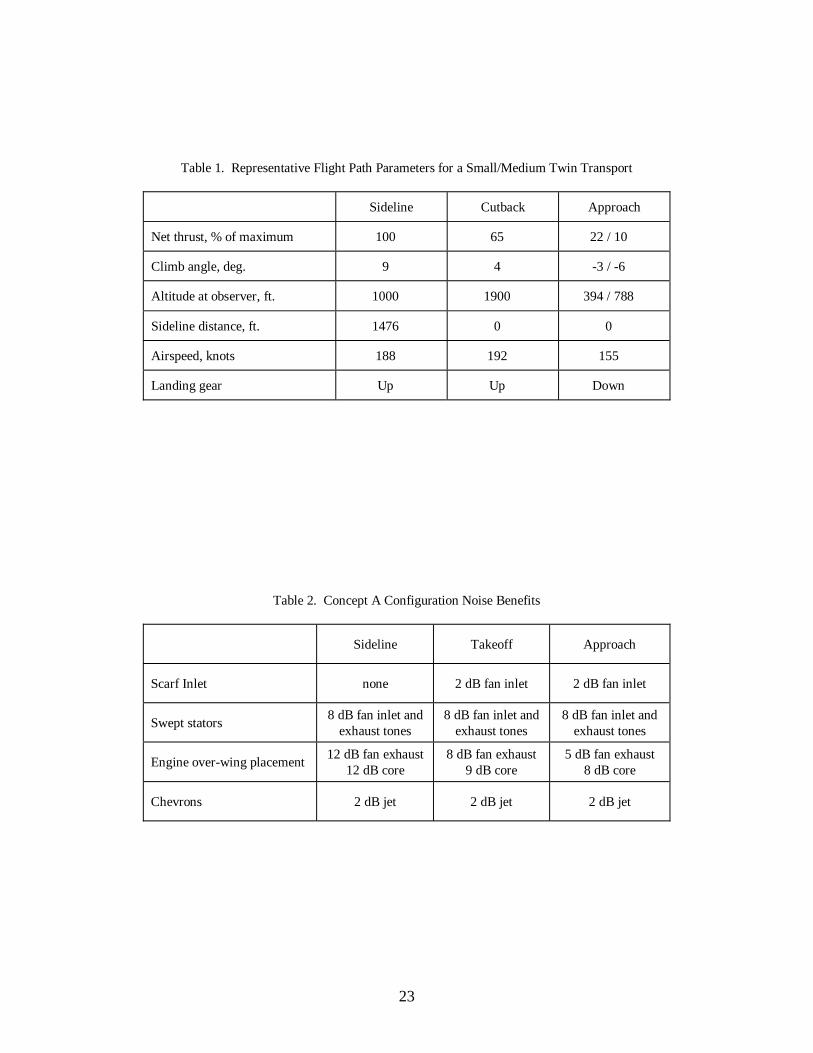
23
Table 1. Representative Flight Path Parameters for a Small/Medium Twin Transport
Sideline Cutback Approach
Net thrust, % of maximum 100 65 22 / 10
Climb angle, deg. 9 4 -3 / -6
Altitude at observer, ft. 1000 1900 394 / 788
Sideline distance, ft. 1476 0 0
Airspeed, knots 188 192 155
Landing gear Up Up Down
Table 2. Concept A Configuration Noise Benefits
Sideline Takeoff Approach
Scarf Inlet none 2 dB fan inlet 2 dB fan inlet
Swept stators8 dB fan inlet and
exhaust tones8 dB fan inlet and
exhaust tones8 dB fan inlet and
exhaust tones
Engine over-wing placement12 dB fan exhaust
12 dB core8 dB fan exhaust
9 dB core5 dB fan exhaust
8 dB core
Chevrons 2 dB jet 2 dB jet 2 dB jet
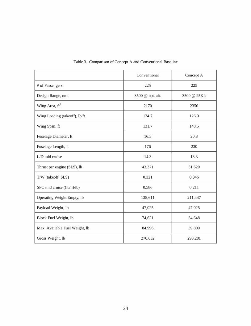
24
Table 3. Comparison of Concept A and Conventional Baseline
Conventional Concept A
# of Passengers 225 225
Design Range, nmi 3500 @ opt. alt. 3500 @ 25Kft
Wing Area, ft2 2170 2350
Wing Loading (takeoff), lb/ft 124.7 126.9
Wing Span, ft 131.7 148.5
Fuselage Diameter, ft 16.5 20.3
Fuselage Length, ft 176 230
L/D mid cruise 14.3 13.3
Thrust per engine (SLS), lb 43,371 51,620
T/W (takeoff, SLS) 0.321 0.346
SFC mid cruise ((lb/h)/lb) 0.586 0.211
Operating Weight Empty, lb 138,611 211,447
Payload Weight, lb 47,025 47,025
Block Fuel Weight, lb 74,621 34,648
Max. Available Fuel Weight, lb 84,996 39,809
Gross Weight, lb 270,632 298,281
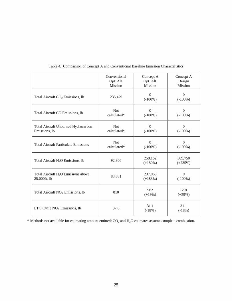
25
Table 4. Comparison of Concept A and Conventional Baseline Emission Characteristics
ConventionalOpt. Alt.Mission
Concept AOpt. Alt.Mission
Concept ADesignMission
Total Aircraft CO2 Emissions, lb 235,4290
(-100%)0
(-100%)
Total Aircraft CO Emissions, lbNot
calculated*0
(-100%)0
(-100%)
Total Aircraft Unburned HydrocarbonEmissions, lb
Notcalculated*
0(-100%)
0(-100%)
Total Aircraft Particulate EmissionsNot
calculated*0
(-100%)0
(-100%)
Total Aircraft H2O Emissions, lb 92,306258,162(+180%)
309,750(+235%)
Total Aircraft H2O Emissions above25,000ft, lb
83,881237,068(+183%)
0(-100%)
Total Aircraft NOX Emissions, lb 810962
(+19%)1291
(+59%)
LTO Cycle NOX Emissions, lb 37.831.1
(-18%)31.1
(-18%)
* Methods not available for estimating amount emitted; CO2 and H2O estimates assume complete combustion.
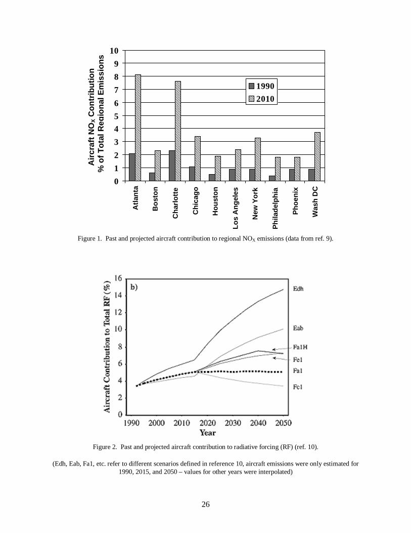
26
Figure 1. Past and projected aircraft contribution to regional NOX emissions (data from ref. 9).
Figure 2. Past and projected aircraft contribution to radiative forcing (RF) (ref. 10).
(Edh, Eab, Fa1, etc. refer to different scenarios defined in reference 10, aircraft emissions were only estimated for1990, 2015, and 2050 – values for other years were interpolated)
Air
craf
tN
OX
Co
ntr
ibu
tio
n%
of
To
talR
egio
nal
Em
issi
on
s
������������������������������������������������������������������������������������������
�������������������������
������������������������������������������������������������������������������������
�����������������������������������
������������������������
�������������������������
������������������������������
��������������������
��������������������
�����������������������������������
0
1
2
3
4
5
6
7
8
9
10
Atl
anta
Bo
sto
n
Ch
arlo
tte
Ch
icag
o
Ho
ust
on
Lo
sA
ng
eles
New
Yo
rk
Ph
ilad
elp
hia
Ph
oen
ix
Was
hD
C
1990���������� 2010

27
Figure 3. Historical trends in engine and aircraft fuel efficiency (ref. 10).
Figure 4. Quiet Green Transport Concept A description.
Basic Concept
– High bypass ratio H2 turbofan engines, LH2
fuel– Over-wing engine placement– Scarf Inlets– Strut-Braced Wing airframe– Steep approach (6°)– “Contrail Avoidance” cruise
Benefits
– Elimination of aircraft emissions of CO2, CO,hydrocarbons, SOX, soot
– Forward and aft noise shielding– Increased wing aero and structural efficiency– Reduced approach noise– Potential to eliminate contrails
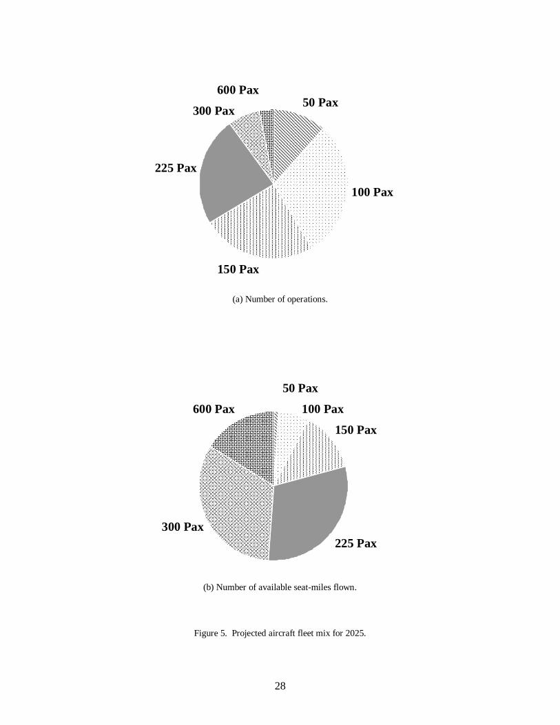
28
(a) Number of operations.
(b) Number of available seat-miles flown.
Figure 5. Projected aircraft fleet mix for 2025.
����������������������������������������������������������������������������������������������������������������������������������������������������������������������������������������������������������������������������������������
������������������������������������������������������������������������������������������������������������������������������������������������������������������������������������������������������������������������������������������������������������������������������������������������������������������������������������������������������������������������������������������������������������������������������������������������������������������������������������������������������������������������������������������������
����������������������������������������������������������������������������������������������������������������������������������������������������������������������������������������������������������������������������������������������������������������������������������������������������������������������������������������������������������������������������������������������������������������������������������������������������������������������������������������
����������������������������������������������������������������������������������������������������������������������������������������������������������������������������������������������������������������
������������������������������������������������������������������������
50 Pax
100 Pax
150 Pax
225 Pax
300 Pax
600 Pax
��������������������������������
������������������������������������������������������������������������������������������������������������������������������������������������������������������������
������������������������������������������������������������������������������������������������������������������������������������������������������������������������������������������������������������������������������������������������������������������������������������������������������
������������������������������������������������������������������������������������������������������������������������������������������������������������������������������������������������������������������������������������������������������������������������������������������������������������������������������������������������������������������������������������������������������������������������������������������������������������������������������������������������������������������������������������
��������������������������������������������������������������������������������������������������������������������������������������������������������������������������������������������������������������������������������������������������������������������������������������������������������
50 Pax
100 Pax
150 Pax
225 Pax300 Pax
600 Pax
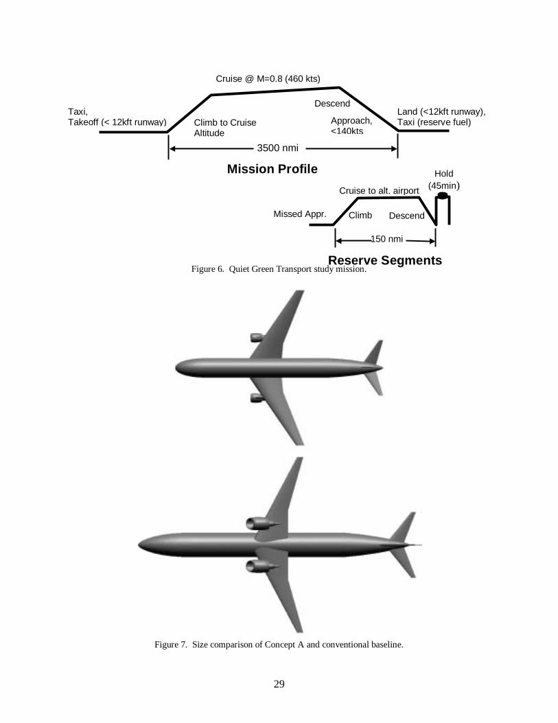
29
Figure 6. Quiet Green Transport study mission.
Figure 7. Size comparison of Concept A and conventional baseline.
Taxi,Takeoff (< 12kft runway) Climb to Cruise
Altitude
Cruise @ M=0.8 (460 kts)
3500 nmi
150 nmi
Reserve Segments
Descend
Approach,<140kts
Land (<12kft runway),Taxi (reserve fuel)
Hold(45min)Cruise to alt. airport
Missed Appr. DescendClimb
Mission Profile
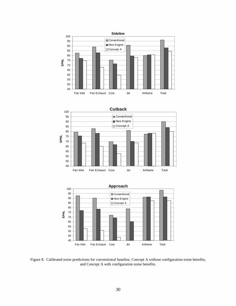
30
Figure 8. Calibrated noise predictions for conventional baseline, Concept A without configuration noise benefits,and Concept A with configuration noise benefits.
Sideline
45
50
55
60
65
70
75
80
85
90
95
100
Fan Inlet Fan Exhaust Core Jet Airframe Total
EP
NL
Conventional
New Engine
Concept A
Cutback
45
50
55
60
65
70
75
80
85
90
95
100
Fan Inlet Fan Exhaust Core Jet Airframe Total
EP
NL
Conventional
New Engine
Concept A
Approach
45
50
55
60
65
70
75
80
85
90
95
100
Fan Inlet Fan Exhaust Core Jet Airframe Total
EP
NL
Conventional
New Engine
Concept A
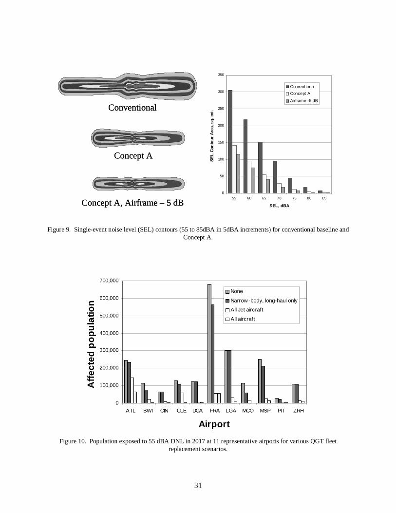
31
Figure 9. Single-event noise level (SEL) contours (55 to 85dBA in 5dBA increments) for conventional baseline andConcept A.
Figure 10. Population exposed to 55 dBA DNL in 2017 at 11 representative airports for various QGT fleetreplacement scenarios.
0
50
100
150
200
250
300
350
55 60 65 70 75 80 85
SEL, dBAS
EL
Con
tour
Are
a,sq
.mi.
Conventional
Concept A
Airframe -5 dB
Concept AConcept A
ConventionalConventional
Concept A, Airframe – 5 dBConcept A, Airframe – 5 dB
0
100,000
200,000
300,000
400,000
500,000
600,000
700,000
ATL BWI CIN CLE DCA FRA LGA MCO MSP PIT ZRH
Airport
Aff
ecte
dp
op
ula
tion
None
Narrow -body, long-haul only
All Jet aircraft
All aircraft
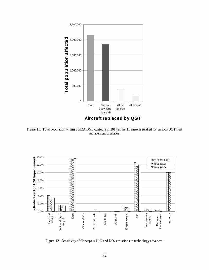
32
Figure 11. Total population within 55dBA DNL contours in 2017 at the 11 airports studied for various QGT fleetreplacement scenarios.
Figure 12. Sensitivity of Concept A H2O and NOX emissions to technology advances.
0
500,000
1,000,000
1,500,000
2,000,000
2,500,000
None Narrow -body, long-
haul only
All Jetaircraf t
A ll aircraf t
Aircraft replaced by QGT
To
talp
op
ula
tion
affe
cted
��������������������
���������������
������������������������������������������������������������
���������������
����������������������������������������������������������������������
��������
����������
��������������������������������������������
��������������������
���������������
���������������������������������������������������������������������������
����������
��������
�����������������������������������������������������������������
����������
��������
�������������������������������������������������������0.0%
2.0%
4.0%
6.0%
8.0%
10.0%
12.0%
14.0%
Str
uctu
ral
Wei
ght
Sys
tem
s&E
quip
Wei
ght D
rag
CLm
ax(T
.O.)
CLm
ax(L
and)
L/D
(T.O
.)
L/D
(Lan
d)
Eng
ine
Wei
ght
SF
C
Fue
lSys
tem
Wei
ght
Res
erve
Req
uire
men
ts
EI
(NO
X)
%R
edu
ctio
nfo
r10
%Im
pro
vem
ent
������ NOx per LTO������ Total NOx
Total H2O
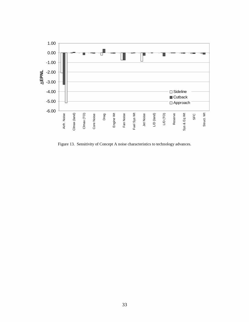
33
Figure 13. Sensitivity of Concept A noise characteristics to technology advances.
-6.00
-5.00
-4.00
-3.00
-2.00
-1.00
0.00
1.00
Airf
r.N
oise
Clm
ax(la
nd)
Clm
ax(T
O)
Cor
eN
oise
Dra
g
Eng
ine
Wt
Fan
Noi
se
Fue
lSys
Wt
JetN
oise
L/D
(land
)
L/D
(TO
)
Res
erve
Sys
&E
qW
t
SF
C
Str
uct.
Wt
∆E
PN
L
SidelineCutbackApproach
REPORT DOCUMENTATION PAGE Form ApprovedOMB No. 0704-0188
Public reporting burden for this collection of information is estimated to average 1 hour per response, including the time for reviewing instructions, searching existing datasources, gathering and maintaining the data needed, and completing and reviewing the collection of information. Send comments regarding this burden estimate or any otheraspect of this collection of information, including suggestions for reducing this burden, to Washington Headquarters Services, Directorate for Information Operations andReports, 1215 Jefferson Davis Highway, Suite 1204, Arlington, VA 22202-4302, and to the Office of Management and Budget, Paperwork Reduction Project (0704-0188),Washington, DC 20503.
1. AGENCY USE ONLY (Leave blank) 2. REPORT DATE
September 20023. REPORT TYPE AND DATES COVERED
Technical Memorandum
4. TITLE AND SUBTITLE
Evaluation of an Aircraft Concept With Over-Wing, Hydrogen-FueledEngines for Reduced Noise and Emissions
5. FUNDING NUMBERS
WU 706-87-11-04
6. AUTHOR(S)
Mark D. Guynn and Erik D. Olson
7. PERFORMING ORGANIZATION NAME(S) AND ADDRESS(ES)
NASA Langley Research CenterHampton, VA 23681-2199
8. PERFORMING ORGANIZATIONREPORT NUMBER
L-18222
9. SPONSORING/MONITORING AGENCY NAME(S) AND ADDRESS(ES)
National Aeronautics and Space AdministrationWashington, DC 20546-0001
10. SPONSORING/MONITORINGAGENCY REPORT NUMBER
NASA/TM-2002-211926
11. SUPPLEMENTARY NOTES
12a. DISTRIBUTION/AVAILABILITY STATEMENT
Unclassified-UnlimitedSubject Category 01 Distribution: StandardAvailability: NASA CASI (301) 621-0390
12b. DISTRIBUTION CODE
13. ABSTRACT (Maximum 200 words)
This report describes the analytical modeling and evaluation of an unconventional commercial transport aircraftconcept designed to address aircraft noise and emission issues. A strut-braced wing configuration with over-wing, ultra-high bypass ratio, hydrogen fueled turbofan engines is considered. Estimated noise and emissioncharacteristics are compared to a conventional configuration designed for the same mission and significantbenefits are identified. The design challenges and technology issues which would have to be addressed to makethe concept a viable alternative to current aircraft designs are discussed. This concept is one of the "Quiet GreenTransport" aircraft concepts studied as part of NASA's Revolutionary Aerospace Systems Concepts (RASC)Program. The RASC Program seeks to develop revolutionary concepts that address strategic objectives of theNASA Enterprises, such as reducing aircraft noise and emissions, and to identify enabling advanced technologyrequirements for the concepts.
14. SUBJECT TERMS
Aircraft Emissions, Aircraft Noise, Hydrogen Aircraft, Advanced Aircraft Concept,15. NUMBER OF PAGES
38Alternative Fuels, Advanced Propulsion Concept, Strut-Braced Wing 16. PRICE CODE
17. SECURITY CLASSIFICATION
OF REPORT
Unclassified
18. SECURITY CLASSIFICATIONOF THIS PAGE
Unclassified
19. SECURITY CLASSIFICATION OF ABSTRACT
Unclassified
20. LIMITATION OF ABSTRACT
UL
NSN 7540-01-280-5500 Standard Form 298 (Rev. 2-89)Prescribed by ANSI Std. Z-39-18298-102