Embed Size (px)
Citation preview
THESIS FOR THE DEGREE OF DOCTOR OF PHILOSOPHY
Evaluation of Biocide Release from Modified Microcapsules
JONATAN BERGEK
Department of Chemistry and Chemical Engineering
CHALMERS UNIVERSITY OF TECHNOLOGY
Gothenburg, Sweden 2017
II
Evaluation of Biocide Release from Modified Microcapsules JONATAN BERGEK ISBN 978-91-7597-524-5 © JONATAN BERGEK, 2017. Doktorsavhandlingar vid Chalmers tekniska högskola Ny serie nr 4205 ISSN 0346-718X Department of Chemistry and Chemical Engineering Chalmers University of Technology SE-412 96 Gothenburg Sweden Telephone + 46 (0)31-772 1000 Cover: Three different microcapsules. To the left, the porosity within the homogeneous polymer matrix has been tuned. In the middle, polyelectrolyte multilayers have been built on the surface of a microsphere. To the right, a sprayed microcapsule is illustrated with its core-shell structure. All three can be loaded with the biocide OIT, here shown as red hexagons. Printed at Chalmers Reproservice Gothenburg, Sweden 2017

III
Evaluation of Biocide Release from Modified Microcapsules
JONATAN BERGEK Department of Chemistry and Chemical Engineering
Chalmers University of Technology
Abstract
Anti-fouling coatings have found use in a wide variety of sectors spanning from biological implants to house paints. Contemporary outdoor paint systems rely on the effect of anti-fouling substances, biocides, when protecting a coated surface against micro-organic growth of mold or algae. Biocides are small molecules and normally mixed directly in the paint during manufacturing. Today´s paint systems lose their anti-growth protection long before the end of their intended lifetime as the biocides are leached and rinsed from the coating by water at a high rate. This problem is related to the high diffusivity of the biocide inside the paint matrix.
A promising improvement can be achieved by encapsulating the biocide and thereby reducing the release rate from the coating. In this thesis, the industrially common biocide 2-n-octyl-4-isothiazolin-3-one (OIT) has been encapsulated in homogenous polymeric microcapsules, using a physical process-based method denoted internal phase separation by solvent evaporation. The biocide has also been encapsulated in inorganic titania microcapsules using a chemical spraying-induced formulation route where hydrolysis and condensation of a titania precursor at the oil-water interface of emulsion droplets forms the shell around the oil core.
The main objective of this work was to explore the mechanisms affecting controlled release from microcapsules. By understanding how, and to which extent, different parameters influence the release of biocides, a prolonged and controlled surface protection of paint and other coatings can be achieved, which is the general purpose of the work. Moreover, the aim was to design release methodologies in order to evaluate the release of biocides.
The results presented in this thesis show that microscopic porosity of the polymer matrix, or free volume, in polymeric microcapsules is affected by the evaporation rate in the formulation step. However, diffusion through the macroscopic porosity in the paint matrix was still rate-determining. Instead, assembly of a polyelectrolyte multilayer on the surface of the capsule could be identified to restrict diffusion to become the rate-determining barrier in a system consisting of encapsulated OIT in a coating. It could also be concluded that by following the spraying-induced technique, up to 50 wt% OIT could be encapsulated in the oil core enclosed within a hydrophilic titanium dioxide shell.
Keywords: Microcapsule, core-shell particle, microsphere, polyelectrolyte multilayer, microscopic and macroscopic porosity, controlled release, 2-n-octyl-4-isothiazolin-3-one, internal phase separation method, airbrush spraying

IV
V
LIST OF PUBLICATIONS This thesis is a summary of the following papers, referred to by Roman numerals in the text. I: Controlled release of microencapsulated 2-n-octyl-4-isothiazolin-3-one
from coatings: Effect of microscopic and macroscopic pores Jonatan Bergek, Markus Andersson Trojer, Alberta Mok and Lars
Nordstierna Colloids and Surfaces A: Physicochemical and engineering aspects, 2014,
458, 155-167 II: Charged microcapsules for controlled release of hydrophobic actives.
Part III: the effect of polyelectrolyte brush- and multilayers on sustained release Markus Andersson Trojer, Helena Andersson, Ye Li, Jonatan Borg*, Krister Holmberg, Magnus Nydén and Lars Nordstierna Physical Chemistry Chemical Physics, 2013, 15, 6456-6466
III: Controlled release of a microencapsulated arduous semi-hydrophobic
active from coatings: Superhydrophilic polyelectrolyte shells as globally rate-determining barriers
Jonatan Bergek, Markus Andersson Trojer, Hermann Uhr and Lars Nordstierna
Journal of Controlled Release, 2016, 225, 31-39 IV: Use of microcapsules as controlled release devices for coatings Markus Andersson Trojer, Lars Nordstierna, Jonatan Bergek, Hans
Blanck, Krister Holmberg and Magnus Nydén Advances in Colloid and Interface Science, 2015, 222, 18-43 V: Formation of titanium dioxide core-shell microcapsules through a
binary-phase spray technique Jonatan Bergek, Björn Elgh, Anders E.C. Palmqvist and Lars
Nordstierna Manuscript
* I changed surname from Borg to Bergek in July 2013.

VI
CONTRIBUTION REPORT FOR THE LISTED PUBLICATIONS
I. Most experimental and major analytical work. Responsible for writing the manuscript.
II. Selected experimental and analytical work. Co-authoring the manuscript.
III. Most experimental and major analytical work. Responsible for writing the manuscript.
IV. Review article. Co-authoring the manuscript, major responsibility in particular for the content in Chapter 3.
V. Most experimental and major analytical work. Responsible for writing the manuscript.

VII
TABLE OF CONTENTS
1 INTRODUCTION .......................................................................................................... 1 1.1 OBJECTIVES .............................................................................................................. 2 1.2 OUTLINE OF THE THESIS ......................................................................................... 3
2 BACKGROUND ............................................................................................................ 5 2.1 PAINT ......................................................................................................................... 5
2.1.1 Titanium dioxide and its Synthesis .................................................................... 6 2.2 ANTIMICROBIAL PROPERTIES ................................................................................ 7
2.2.1 Biocides ................................................................................................................. 8 2.2.1.1 2-n-octyl-4-isothiazolin-3-one (OIT) ......................................................... 8
2.2.2 Surface Flux .......................................................................................................... 9 2.3 MICROENCAPSULATION ........................................................................................ 11
2.3.1 Microcapsule Formulation Methods ............................................................... 11 2.3.1.1 Internal Phase Separation by Solvent Evaporation .............................. 12 2.3.1.2 Airbrush Pen Microcapsule Formation .................................................. 14
2.3.2 Polyelectrolytes and Polyelectrolyte Multilayers .......................................... 15 2.3.3 Porosity ............................................................................................................... 16
3 FORMULATION ......................................................................................................... 19 3.1 INTERNAL PHASE SEPARATION BY SOLVENT EVAPORATION .......................... 20
3.1.1 Tuning the Solvent Evaporation ...................................................................... 21 3.1.2 Building Polyelectrolyte Multilayers ............................................................... 22
3.2 AIRBRUSH PEN MICROCAPSULE FORMATION ................................................... 23
4 RELEASE METHODOLOGY ................................................................................. 25 4.1 METHODOLOGICAL FRAMEWORK ....................................................................... 25 4.2 RELEASE FROM MICROCAPSULES ........................................................................ 26
4.2.1 The Setup ............................................................................................................ 27 4.2.2 The Analysis ....................................................................................................... 29
4.3 RELEASE FROM COATINGS ................................................................................... 30 4.3.1 The Setup ............................................................................................................ 31 4.3.2 The Analysis ....................................................................................................... 32
4.4 DIFFUSION MODELS .............................................................................................. 32 4.4.1 Microspheres ...................................................................................................... 33 4.4.2 Coatings .............................................................................................................. 33
5 ANALYTICAL TECHNIQUES ................................................................................ 35 5.1 LIGHT MICROSCOPY .............................................................................................. 35 5.2 DIFFERENTIAL SCANNING CALORIMETRY ......................................................... 36 5.3 TENSIOMETRY ........................................................................................................ 36 5.4 UV/VIS SPECTROPHOTOMETRY ........................................................................... 36

VIII
6 RESULTS AND DISCUSSION ................................................................................. 39 6.1 ENCAPSULATION OF BIOCIDES ............................................................................. 39
6.1.1 Porosity ............................................................................................................... 42 6.1.2 Polyelectrolyte Multilayers .............................................................................. 47 6.1.3 Airbrush Pen Microcapsule Formation .......................................................... 50
6.2 ANTIMICROBIAL PROPERTIES .............................................................................. 55
7 CONCLUDING REMARKS ..................................................................................... 59
ACKNOWLEDGEMENTS ................................................................................................ 61
REFERENCES ..................................................................................................................... 63

1
1 INTRODUCTION Growth of mold and algae on painted façades is a worldwide problem. The esthetic problems are often easy to see; grey, black, or green stains change the appearance undesirably. However, paint is still applied to protect the underlying surface and the way of preserving has changed over time, often due to regulations after discoveries of upcoming environmental issues connected to the selected mode of protection [1]. Toxic metal compounds including tin and mercury have been previously used to prevent microbial growth. However, such compounds are now banned [2]. Today, the paint industry relies on metal-free and less hazardous biocides as protection against growth [1, 3, 4]. Almost all biocides used in the coatings industry are small and often hydrophobic molecules and they have been selected due to their capability to destroy or repulse organisms as mold and algae via biological or chemical processes [5]. The typical procedure for industrial paint formulation is to directly mix the biocides in the paint. Subsequent to paint application and drying, the small biocides are diffusing more or less freely within the paint matrix, which is both positive and negative from a user’s perspective. Biocides which are able to quickly migrate in the paint matrix will conserve the formulation by preventing microbial growth at the surface of the paint layer [2, 6]. However, a high diffusivity, i.e. rate of migration, inside the dried paint matrix will also contribute to a fast leakage of biocide from the applied paint as rain rinses the painted surface. High diffusivity leads consequently to premature loss of surface protection [3, 5, 7].
1

2
One way to minimize the losses of biocide and to prolong the surface protection against micro-organic growth is by using microcapsules. In this thesis, microcapsules are defined as solid particles in the micrometer size range and can be of both core-shell structure, or homogenous polymer monolithic form. The latter will in parts of the thesis be denoted more specifically as microspheres [8]. Microcapsules are too large to diffuse inside the polymeric paint matrix and they are also easily homogenously mixed in the paint and embedded in the dry coating [9]. These properties give the opportunity to control the release of biocide into the paint matrix via the properties of the microcapsule, since the biocide first has to diffuse inside the microcapsule, then be released from it, thereafter diffuse inside the paint matrix, and finally migrate to the outermost surface. A controlled release from microcapsules can prolong the protection of the paint since the biocides will stay in the paint matrix for a longer time. The release rate of a selected biocide can be tuned to a great extent by tailoring several physicochemical properties of the microcapsule. Shell thickness, particle size, choice of core and shell material as well as surface charge density are some of the parameters that can be tailored in order to control the release and prolong the protection against microbial growth. The microcapsules can also be modified after encapsulation, e.g. by adding additional shells such as polyelectrolyte multilayers.
1.1 OBJECTIVES The main scientific objective of this work has been to explore the mechanisms affecting the release from microcapsules. By understanding how, and to what extent, different parameters influence the release of biocides, a prolonged and controlled surface protection of paint and other coatings can be achieved, which is the general purpose of the work. As part of this work, a generic methodology has been designed to study the release of biocides. The goal was to find a setup suitable for different release systems as well as model applications. The aim of Paper I was to investigate and analyze the effects of microscopic and macroscopic pores in microcapsules and coatings, respectively on the release of the biocide 2-n-octyl-4-isothizolin-3-one (OIT). In Paper II, the addition of a very hydrophilic and charged barrier on the microcapsule and its effect on the release was investigated. Polyelectrolyte multilayers were assembled on microcapsules using the diblock copolymer poly(methyl methacrylate)-block-poly(sodium methacrylate) and the release was measured using the dye Disperse Red 13. The aim of Paper III connects Paper I and Paper II. The study was done to evaluate the effects of using microcapsules with polyelectrolyte multilayers as containers for OIT and

3
the release of the biocide. A commercially available paint was used and dried for several different time intervals, to investigate a possible upcoming macroscopic porous structure, depending on drying time, which would influence the release rate of OIT. Also, a study was performed to evaluate the antimicrobial properties of OIT on a common biofouler. Paper IV is a review concerning the use of microcapsules as controlled release devices for coatings. It puts the research in Paper I-III in a wider perspective. In Paper V a new route to encapsulate OIT was investigated. Here, microcapsules were produced consisting of a titanium dioxide (TiO2) shell, and an oil as core and as such, these inorganic microcapsules are intrinsically different in terms of physicochemical properties compared to the previously mentioned polymeric ones. These microcapsules have been formulated using a spray technique, and can be interesting in outdoor paint formulations by also fulfilling the role as pigment for which TiO2 is commonly used.
1.2 OUTLINE OF THE THESIS This thesis is divided into seven chapters focusing on microencapsulation and the release of biocide from microcapsules. After this introduction, Chapter 2 covers essential background related to the work; paint, antimicrobial properties, and microencapsulation. Chapter 3 focuses on the microencapsulation techniques used, while Chapter 4 describes the release measurements for the active substances from suspension and from a coated surface, both freely and encapsulated. In Chapter 5 the analytical tools used to characterize the microcapsules and measure the release are described. Chapter 6 discusses the results from the articles while concluding remarks can be found in Chapter 7.

4

5
2 BACKGROUND In Chapter 2, a short background is given focusing on paint, its general composition, the selected biocide and the theoretical basis for microencapsulation.
2.1 PAINT Paint can be found almost everywhere in our everyday life, and its applications ranges from esthetical to protective, or often both. It is used both indoors and outdoors, in extreme environments as under water, in spaces exposed for fire or tremendous pressures, or surfaces which need to endure heavy forces. To be able to perform under these different conditions, the paint is modified to fit the specific task, and at the same time developments in the field related to environmental considerations, and constraints in health and safety legislation, drive changes in the paint industry [10, 11]. In all cases, paint is a complex formulation of ingredients including binder, pigment, solvent and additives [12]. The binder is the component that identifies the paint, as alkyd, acrylic (latex) or vinyl [12]. In waterborne paint, which is the focus in this work, acrylic latex is widely used as binder mainly because of its stability under excess of UV, alkalinity and heat, its good exterior durability, and film clarity [13]. During paint drying, the latex particles (~100 nm in size) merge together as water continuously evaporates and form a film. However,
2

6
the particle merging is seldom fully complete resulting in porosity within the paint layer, here denoted macroscopic porosity and discussed in Section 2.3.3. The solvent is carrier of the paint formulation, aiding the application of the paint at a surface. There are generally two commercial categories of paint with regard to solvent of the product for the consumer to choose between; waterborne or solvent-based [11, 12, 14]. By definition, waterborne refers to the broad category of coatings using water as main volatile liquid component [11]. In this work the focus has been on waterborne acrylic paints intended for façade application. Pigments have been a part of paint formulations as long as humans have been painting [15]. Pigments are more specifically solids dispersed in paints and can be both organic or inorganic materials where organic pigments are most often used for decorative purposes while inorganic pigments more often have a protective purpose [12]. Carbon black is the dominant black pigment while titanium dioxide is the most common white pigment [15]. Titanium dioxide has been explored in this work as shell material for microcapsules, and will be described in Section 2.1.1 below. Additives cover a range of substance categories, usually fillers or thickeners, but also more specific substances intended to improve a certain property [14]. In several of these cases surfactants are used, e.g. as dispersant for the pigment, as emulsifier for the binder, and to improve wetting for the ingoing components [16]. Other specific additives are antifoaming agents added to prevent foaming during the preparation of the paint [14], and preservatives as biocides, more extensive described in Section 2.2.1.
2.1.1 Titanium dioxide and its Synthesis Titanium is the ninth most common element in the earth´s crust, and several common minerals contain titanium [17]. Titanium dioxide, or titania, is from a technological perspective the most important of the titanium compounds, and it occurs in nature in three different crystal forms: rutile, anatase and brookite, in addition to the amorphous phase [18]. A large quantity of titania, approximately 90 %, is used as white pigment especially in different paints, but also to color plastics, paper and rubber [17]. It is titania in the rutile form that is most important as white pigment, with its light scattering properties, non-toxicity and chemical stability, but also anatase is used commercially [12, 15, 19]. Titanium dioxide is not only used in formulations for white paints, it is also included in other color formulas to adjust the brightness of the final color [12, 20]. The two main manufacturing processes for producing titanium dioxide pigment at industrial scale are the chloride and the sulfate processes [21], both including steps involving high-temperature.

7
There are also several different low-temperature synthesis routes of titanium dioxide where two common methods are using either inorganic precursors, as titanium(IV) tetrachloride, TiCl4, or organic precursors as titanium alkoxides, Ti(OR)n [22]. In this work, organic precursors have been used in a new fabrication route for core-shell microcapsules (Paper V). Titanium alkoxides, Ti(OR)n, are highly susceptible to nucleophilic attack. Upon contact with water, titanium alkoxides are rapidly hydrolyzed via nucleophilic substitution resulting in the loss of a protonated alkoxy group [23], see Figure 1. Condensation of the formed hydrolysis product may proceed via three different condensation reaction: alcoxolation, oxolation, and olation [24], as shown below. Alcoxolation proceeds via a nucleophilic attack resulting in the release of an alcohol. Oxolation and olation proceeds via nucleophilic attack with water as the leaving group. As the hydrolysis of titanium alkoxide approaches completion, oxolation and olation become the predominating condensation reactions of the hydrolyzed titania species.
Figure 1. Hydrolysis and condensation routes in titanium dioxide formation.
2.2 ANTIMICROBIAL PROPERTIES An essential trait of higher organisms is their ability to protect themselves from biofouling, i.e. unwanted growth of microbes such as fungi, algae and bacteria. Man-

8
made materials lack this important protection and microbial cells can attach and under the right conditions grow and survive on a surface [25, 26]. There are several ways to prevent microbial growth on a surface, as by e.g. physical grounds or chemical, as using biocides [27]. Biocides (Section 2.2.1) used for protection of coated surfaces have been the focus in this work and the antimicrobial effect is determined by the surface concentration of the biocide, which depends on its surface flux from the coated surface, this will be addressed in Section 2.2.2. The antimicrobial properties of coatings are extensively treated in Paper III and Paper IV.
2.2.1 Biocides Biocides have been used for protection in coatings and materials since the 1950´s [2]. Due to regulations regarding environmental issues, a large portion of the development in biocide technology has focused on finding more environmental friendly substitutes for e.g. tin and mercury based products [2]. However, it is difficult to find environmentally sound substitutes with equivalent antifouling properties as the banned organometallic compounds. These compounds were harmful against many different organisms, while more environmental friendly substances are only effective against more specific microbes. A way could be to instead formulate paints consisting of a cocktail of biocides, all with different efficacy profiles but at the same time showing a rapid degradation when leached out to the surrounding environment [28-30], as discussed in Paper IV. 2.2.1.1 2-n-octyl-4-isothiazolin-3-one (OIT) One interesting group of biocides is the isothiazolinones which are biologically active, heterocyclic aromatic compounds [31]. These molecules are electrophilically active and their degradation is improved by readily reacting with the surrounding, as water and soil [32]. It has been suggested that this environmental degradation proceeds by ring opening through the nitrogen-sulfur bond, where progressive hydrolysis and oxidation produces sulfur, malonic acid, methylamine hydrochloride, and eventually leading to the formation of short-chain carboxylic acids and carbon dioxide [2].
Figure 2. The molecular structure of 2-n-octyl-4-isothiazolin-3-one, abbreviated OIT.
This work has specifically focused on 2-n-octyl-4-isothiazolin-3-one (OIT), see Figure 2, which is a semi-hydrophobic biocide often used commercially in the paint industry but also in leather and cardboard products, as well as in polymeric materials as PVC [6, 32]. OIT protects by preventing growth at the surface of the paint layer. The biocide must therefore be able to migrate to the outermost surface of the coating as mentioned in the introduction [2, 6], and subsequently penetrate the cell wall of the microbe. Cell death

9
within the microbe will eventually occur, in the cytoplasm, when the electron deficient sulfur of the isothiazolinone reacts with the thiols in proteins, leading to impairment of their enzymatic functions [31]. This route gives OIT the advantage of being a broad-spectrum biocide, not as selective as many other biocides. In contemporary commercial paint products, OIT is found as a freely dispersed additive in the wet paint formulation. A prolonged protection could most simply be reached by increasing the surface flux over time by increasing the biocide concentration in the paint [2]. One problem is that biocides in general, and the isothiazolinones as OIT in particular, can act as softeners which may change the thermo-mechanical properties of the paint. Furthermore, most antimicrobials are expensive ingredients and there is often a maximum allowed concentration of biocide in paint products due to environmental regulations. The above-mentioned features make encapsulation of OIT, to obtain prolonged protection, an interesting topic.
2.2.2 Surface Flux The surface flux is here defined as the amount of biocide that leaves the coated surface per unit area and unit time. A main concern when using biocides as protecting agents in a coating is its fast diffusion in the polymer paint matrix and out from the outermost surface to the surrounding. The antifouling protection will be lost when the surface flux of the active ingredient is below a certain critical value, as described illustratively in Figure 3, and discussed and visually inspected in Paper III. The value of this critical surface concentration depends on the given biocide and the biological species. The surface flux from the coating ṁSURF, which depends on the time t and the biocide concentration in the coating mC(t), will determine the average surface concentration m(t) within a small finite volume element in immediate proximity to the coating surface. The surface concentration, which also depends on the rate of biocide removalṁOUT (as leaching, degradation, microbial absorption, most often following first order kinetics [33]), must be kept above a minimum level, which then is the critical surface concentration of the specific biocide. 𝑚 t = 𝑚SURF mc t ,t −𝑚OUT(m t ,t)
(1)
m t = 𝑚 t dtm 0 = 0
)
*
(2)
The surface flux is equivalent to the derivative of the release models discussed in Section 4.4, see also Paper III. It is here normalized with biocide mass mTOT and surface area As, giving fFLUX(t) according to
fFLUX t =𝑚SURF(t)
As=
mTOT
As
∂∂t
fRELEASE(t) (3)

10
where the analytical solution to fRELEASE(t) is presented in Paper I. The diagram in Figure 3 describes how the antimicrobial effect is related to the time dependent surface flux of biocide from the surface and critical surface flux. The first curve, A, represents a typical system with freely dispersed biocide in paint, where the concentration of biocide at the surface rapidly is decreased and found below the critical surface concentration, meaning that the protection is lost. B shows illustratively that a longer protection time can be achieved by increasing the ingoing biocide concentration. However, this can only be seen as a quick fix since the problems discussed in Section 2.2.1, as softening of the system, expensive ingredient and environmental regulations, prevent this to function in larger scale. Curve C in Figure 3 exemplifies the aim of this work: a slow release rate of biocide out from the coated surface protecting the same, thus stays above the critical surface concentration, for a significantly longer period of time than the cases A and B.
Figure 3. Three different scenarios with surface flux of biocide over time. The red horizontal line represents the critical surface concentration. A represents a system where the biocide is freely dispersed in coating, where a rather low amount of biocide is rapidly released resulting in only short protection time. B shows illustratively that a longer protection time can be achieve by increasing the ingoing biocide concentration. In this work, the aim is to achieve a slow release rate of biocide out from the coated surface protecting the same for a much longer time, as exemplified by curve C.

11
2.3 MICROENCAPSULATION Microencapsulation is a fabrication method where small (1-1000 µm) solid particles, liquid droplets, or gas bubbles are coated with a thin layer of coating or shell material [34, 35]. Information about preparation of microparticles dates back to 1950s when Green and Schleicher produced microencapsulated dyes for the manufacture of carbonless copy paper, which is still used commercially [35-37]. However, encapsulation systems have been used by humans long before labeled as a specific technique [38], and the principle mimics the nature´s way of isolating essential processes, and how it protect and release active substances in a controlled manner [39]. The main reason for encapsulation may vary depending on the aim of the application but it is often to protect and/or control the release of an active substance [35, 40, 41]. Microencapsulation can be found in several different industrial areas [42] and microcapsules are for instance very common in the pharmaceutical industry as transportation reservoirs for drugs [43-45]. Here, the release of a drug often has to be immediate when addressed, and is often triggered physically or chemically by e.g. pH changes, temperature variations, or light [46-48]. Microencapsulation can also be found in industrial sectors as agriculture [35, 49, 50], food [51-54], textiles [41, 55] and the coating industry [9, 56, 57].
2.3.1 Microcapsule Formulation Methods There are many different techniques used to synthesize microcapsules. The methods can be divided into physical, chemical or mechanical routes, or combinations of these [34, 40, 42]. Some of the common methods are listed in Table 1. Table 1. Common methods for microcapsule preparation.
Chemical processes
Physical processes (Physico-chemical)
Mechanical processes (Physico-mechanical)
- Chain growth or Step
growth (polycondensation) polymerization
- Coacervation/Phase separation
- Spraying
- Interfacial polymerization
- Self-assembly - Fluid-bed coating
- Emulsion polymerization - Sol-gel encapsulation - Pan coating - Suspension
polymerization - Polyelectrolyte layer-
by-layer assembly - Electrostatic
encapsulation
The techniques based on coacervation, or phase separation, are the broadest class of encapsulation methods [35, 58]. There are three main methods of coacervation if long term controlled release is intended: internal phase separation (see Section 2.3.1.1), multiple emulsion route; and interfacial polymerization [58]. This thesis will focus on core-shell particles, also called microcapsules, and microspheres which are homogenous polymer matrices. The spectrum of sizes, shapes and morphology

12
of microparticles is broad [34, 35, 40] and examples of microcapsule outcomes can be found in Figure 4.
Figure 4. Possible outcomes of the morphologies of microcapsules (a)-(d) and two additional possible phase separation outcomes when following the internal phase separation method (e)-(f).
2.3.1.1 Internal Phase Separation by Solvent Evaporation The internal phase separation, induced by solvent evaporation, was described by Loxley and Vincent 1998 [59] and is one of the chosen microencapsulation techniques in this thesis. It is a physicochemical versatile, straightforward and industrially applicable method. Also, the internal phase separation method gives an almost full encapsulation yield of the active substance [40]. The route, described in Figure 5, starts with the formation of an oil/water emulsion where the continuous phase consists of water and a dispersant, often a water-soluble and surface-active polymer. The oil phase includes a volatile solvent, ingredients for the microcapsule core and shell, and an active substance. The volatile solvent has to have low miscibility in water, be able to dissolve the core oil and be a good solvent for both the shell-forming polymer and the active substance. After the emulsion step, a phase separation of the polymer within the droplets occurs due to evaporation of the volatile solvent. The polymer-rich phase migrates to the interface starting to create a shell. When all volatile solvent has evaporated the microcapsule has got its final structure. If producing microspheres, the setup is identical except no core-material is used.

13
Figure 5. The microencapsulation process via the internal phase separation method. (1) The encapsulation starts with an O/W emulsion where the dispersed oil phase contains the core material, the shell material and the biocide dissolved in a volatile solvent. (2) As the volatile solvent evaporates, phase separation of the polymer within the droplets occurs and (3) the polymer-rich phase migrates to the interface. When all volatile solvent has evaporated, the microcapsule is formed. (4) When the volatile solvent evaporates a homogenous polymeric sphere starts to get its shape. (5) The final microsphere is formed when all volatile solvent has evaporated.
To be able to form capsules with core-shell morphology following the internal phase separation method by solvent evaporation, the polymer (index p) needs to wet the oil (index o) and aqueous phase (index w), i.e. spreading between the oil and water. The definition of the spreading coefficient Sp is found in Equation 4: Sp = ∆Gp
c − ∆Gpa = γow − (γpw + γop) (4)
where ΔGc
p is the free energy for cohesion, ΔGap the free energy for adsorption and γ ij
the interfacial tension between phases i and j (described above). A derivation has been made by Torza and Mason [60] to be able to predict the morphology of droplets of three immiscible liquids in terms of their spreading coefficients. Loxley and Vincent expanded the theory to include solid polymers [59]. With the precondition γow > γop, there are three possible spreading conditions [59, 60]: So<0;Sw<0;Sp>0; (5)
So<0;Sw<0;Sp<0; (6)
So<0;Sw>0;Sp>0; (7)
The microcapsule will obtain core-shell morphology if the conditions in Equation 5 are fulfilled while Equation 6 generates so-called acorn particles, and Equation 7 results in separate oil and polymer droplets. In addition, Trongsatitkul and Budhlall [61] have suggested that multicore-shell particles may form if Sp>>0. If aiming for producing microspheres, the experimental procedure is equivalent to that of microcapsules but the spreading coefficient discussed above is not applicable as the only interface is that between polymer and water phase.

14
2.3.1.2 Airbrush Pen Microcapsule Formation OIT has been found to be problematic to encapsulate in polymeric microcapsules with an oil-core following the internal phase separation method due to its lowering of the oil-water interfacial tension, experimentally tested in Paper I. At the same time, a hydrophilic barrier has been found to be a successful way of decreasing the release rate of OIT out to the surrounding, as evaluated in Paper III. Metal oxide shells can then be another viable alternative to polymeric or composite barriers. Titanium dioxide, titania, is cheap, abundant, environmentally benign, and non-toxic. While polymeric barriers typically are synthesized or formulated using harsh organic solvents, a plethora of titania synthesis routes are known, many of which are waterborne or based on non-hazardous solvents [62]. Furthermore, titania may be synthesized from both hydrophobic and hydrophilic precursors [63], enabling innovative emulsion and microemulsion reaction systems to be formulated. There are ways to formulate core-shell microcapsules consisting of a titania shell, using spray techniques [64, 65] or from non-aqueous emulsions [66, 67]. In order to find a formation route to encapsulate OIT in a core-shell microcapsule with a hydrophilic inorganic shell, a novel, fast and straightforward process was investigated, schematically illustrated in Figure 6. The idea was to encapsulate OIT together with an oil within a shell of titanium dioxide, a material already found in many outdoor paints, as pigment. The setup starts with the formulation of an oil phase and a water phase. The oil phase, consisting of titanium alkoxide and biocide both molecularly dissolved in a so-called core oil, is mixed before added to one of two containers connected to an airbrush pen. In the second airbrush container, a water phase is added.
Figure 6. A. The airbrush setup. Nitrogen gas is used as propellant. B. One container is filled with oil phase and the other container is filled with water phase, and the two solutions are pressed out together through the small spray nozzle. C. The formation of core-shell microcapsules initiates in the direct vicinity of the spray nozzle, when titanium precursor in the oil droplets comes in contact with surrounding water, and starts to form titanium dioxide in the interface between water and oil. The final product is microcapsules suspended in water phase.
Immediately after filling the two containers with oil phase and water phase, respectively, the spraying is started, and microcapsules are formed. The end product is well-defined

15
core-shell microcapsules suspended in water phase. The exact physical and chemical steps in the fabrication is still not completely understood yet but discussed in Paper V. A plausible explanation is that both the hydrolysis and the following condensation occur in the nozzle and also directly after leaving the same.
2.3.2 Polyelectrolytes and Polyelectrolyte Multilayers Since polymeric microcapsules formulated by the internal phase separation can display premature release of their encapsulated active substance [8, 68], thermodynamic or kinetic approaches (the theory is presented in Chapter 4) can be interesting ways to circumvent this drawback [69]. A kinetic approach is discussed in next section. A thermodynamic approach is to build a hydrophilic barrier at the surface of the microcapsule, as a polyelectrolyte multilayer [70]. The adsorption of polyelectrolytes at a surface, for instance the surface of a microcapsule, is governed mainly by electrostatic interactions and the outcome is therefore very dependent on the salt concentration [71, 72]. At low salt concentrations and if the surface has the same sign of the charge as the polyelectrolyte, only small amounts, if any, will adsorb [73, 74]. Also, if the surface has no charge, the result will be only week adsorption. If we instead consider high salt concentrations, the adsorption of polyelectrolytes of opposite charge as compared to that of the surfaces is very strong if there is also a non-electrostatic interaction between the two. This is due to entropy gain from the release of surface bound counter ions [75]. The outcome of the adsorption depending on salt concentration, polymer and surface charge can be found in Figure 7. As can be noticed, the adsorption of the polyelectrolyte at a charged surface is much more affected at low salt concentrations than at high.
Figure 7. A schematic view of the adsorption of polyelectrolytes at a surface under various conditions for salt concentrations, cs, polymer charge density and surface charge density.
16
The assembly of polyelectrolyte multilayers, so called PEMs, using the Layer-by-Layer (LBL) technique is achieved due to the surface charge inversion. This deposition technique was described by Iler [76] and developed by Decher on planar macroscopic substrates [70], and is an efficient way for controlled surface modification [77]. Möhwald and co-workers expanded the PEM assembly to microscopic colloidal surfaces [78]. To be able to build multilayers using LBL, the salt concentration is of outmost importance as described above. Also, the first charged layer needs to be anchored to the surface [79]. The reason to use polyelectrolyte multilayers in this work, as in Paper II and Paper III, is to build a hydrophilic barrier at the surface of the microcapsule to reduce the release of hydrophobic biocides to a surrounding medium.
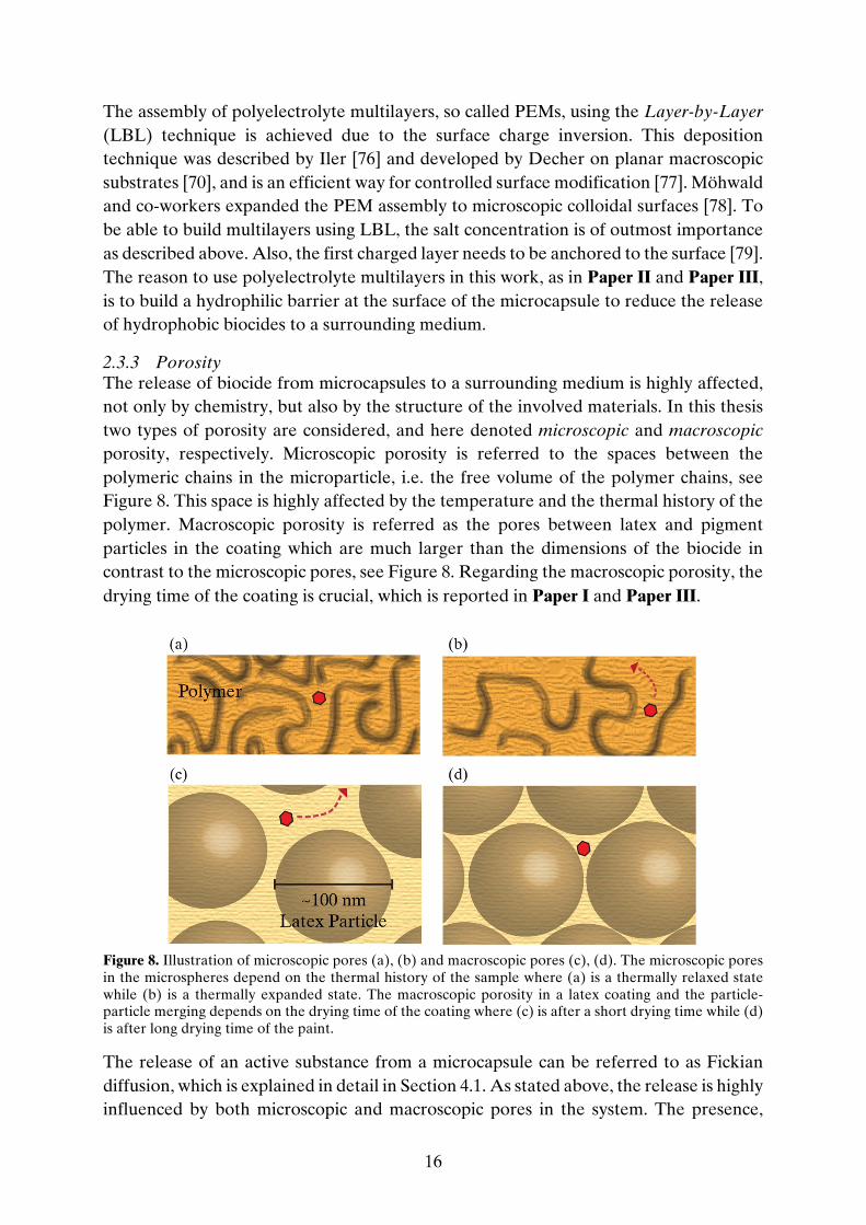
2.3.3 Porosity The release of biocide from microcapsules to a surrounding medium is highly affected, not only by chemistry, but also by the structure of the involved materials. In this thesis two types of porosity are considered, and here denoted microscopic and macroscopic porosity, respectively. Microscopic porosity is referred to the spaces between the polymeric chains in the microparticle, i.e. the free volume of the polymer chains, see Figure 8. This space is highly affected by the temperature and the thermal history of the polymer. Macroscopic porosity is referred as the pores between latex and pigment particles in the coating which are much larger than the dimensions of the biocide in contrast to the microscopic pores, see Figure 8. Regarding the macroscopic porosity, the drying time of the coating is crucial, which is reported in Paper I and Paper III.
Figure 8. Illustration of microscopic pores (a), (b) and macroscopic pores (c), (d). The microscopic pores in the microspheres depend on the thermal history of the sample where (a) is a thermally relaxed state while (b) is a thermally expanded state. The macroscopic porosity in a latex coating and the particle-particle merging depends on the drying time of the coating where (c) is after a short drying time while (d) is after long drying time of the paint.
The release of an active substance from a microcapsule can be referred to as Fickian diffusion, which is explained in detail in Section 4.1. As stated above, the release is highly influenced by both microscopic and macroscopic pores in the system. The presence,

17
magnitude, and distribution of microscopic porosity depends on the route of solvent evaporation, which is further explained in Section 3.1.1 below while macroscopic porosity is affected by the drying time of the paint, see Section 6.1.1.

18

19
3 FORMULATION Here, the main routes for microcapsule production will be explained in detail. The end products are gathered in three groups of different microcapsules all loaded with the biocide OIT, see Figure 9.
Figure 9. The three different microcapsules. To the left, the porosity within the homogeneous polymer matrix has been tuned. In the middle, polyelectrolyte multilayers have been built on the surface of a
The
rmal
ly
rela
xed
stat
e
Thermall
y
expan
ded st
ate
3

20
microsphere. To the right, the sprayed microcapsule is illustrated with its core-shell structure. All three can be loaded with the biocide OIT, here shown as red hexagons.
3.1 INTERNAL PHASE SEPARATION BY SOLVENT EVAPORATION The internal phase separation by solvent evaporation has been the selected method when producing polymeric microcapsules, as investigated in Paper I-IV. For the initial investigations of microcapsule production where a core-shell structure is intended, n-hexadecane has been used as core oil. Regarding the shell material, poly(methyl methacrylate) (PMMA) has been the main choice. PMMA is a widely used polymer and goes under common brand names as Plexiglas® or Acrylite®. The main advantages are its low price, optical properties, the low sensibility to UV light, and its overall weather resistance [80], all important parameters for ingredients in façade coating. The compatibility between microcapsules or microspheres and the coating is very important since a homogenous mixture is crucial as final coating product. PMMA is a moderately hydrophobic polymer and this can be disadvantageous with respect to the release of a given biocide. Whether this is the case or not depends in turn on the physicochemical properties of the biocide. Previous studies have shown that biocides, often small semi-hydrophobic molecules, are more soluble in the PMMA shell than in the very hydrophobic alkane core, making the benefits of using core-shell structure questionable [81]. This is one of the reasons why microspheres, spherical particles only consisting of PMMA and biocide, were used in several studies in this work. The microspheres were produced following the recipe described by Loxley and Vincent [59] (see also Section 2.3.1.1) without adding any oil as core material. Two different homogenous PMMA matrix microspheres loaded with OIT have been formulated in this work where the main recipes differ concerning the solvent evaporation procedure as well as the water dissolved dispersant, as described in detail in Sections 3.1.1 and 3.1.2, respectively. All the chemicals used in these recipes are found in Chart 1.

21
Chart 1. Molecular structure and abbreviations of the chemicals used in internal phase separation experiments, including molecular weight (Mn), critical micelle concentration (CMC), and UV adsorption maximum (λmax) where relevant.
3.1.1 Tuning the Solvent Evaporation In Paper I, a water phase, consisting of 1 wt% non-ionic surfactant PVA (95 % prehydrolyzed) and water of MilliQ grade was prepared as a first step. The oil phase consisted of 53 ml dichloromethane (DCM) as volatile solvent, 4.95 g PMMA (350,000 Mw) as polymer matrix material, 0.55 g of the biocide OIT, and 5 ml of the aiding solvent acetone. During emulsification, the entire oil phase was slowly added (during 120 s) under stirring at 5,000 rpm, using a homogenizer, to 80 ml of the continuous water phase. The emulsification was carried out in a round bottom flask, immerged in a room-temperature water bath, and kept running for an additional 60 minutes under stirring at

22
10,000 rpm. The emulsion was then poured into 120 ml water phase and stirred for several minutes by gentle magnetic mixing, before the evaporation started. In this work, the evaporation method and time of evaporation have been evaluated by analyzing one rapid and one slow evaporation procedure, respectively. As standard, the evaporation of volatile solvent was performed without instrumental force and the solvent is evaporated in a fume hood under slow magnetic stirring from an open 600 ml Griffin beaker. It takes approximately 24 hours until complete evaporation following this route. In order to decrease the time of the evaporation step, a parallel procedure with a rotary evaporator has also been evaluated. The solvent was here evaporated under forced low pressure which results in a significantly faster evaporation, a few hours in our experiments. In both cases, to compensate for water evaporation, pure water was added to set the final suspension to 200 ml thus giving 2.75 wt% of microspheres with 10 wt% OIT content. Different routes of evaporation can be supposed to induce changes in the microscopic porosity of the polymeric microsphere. The hypothesis here was that fast evaporation, and thereby fast polymer phase separation within the emulsion droplet, freezes the polymers in non-equilibrium conformations. In order to assess this hypothesis, the polymer in the microsphere was thermally relaxed by post heat treatment. Heat treatment of the capsules kept in suspension could not be carried out under atmospheric pressure and required an autoclave setup as the PMMA glass-transition temperature (Tg, up to 122 ◦C) is higher than the boiling point of water. By preceding analysis of Tg with respect to OIT content in microspheres, using differential scanning calorimetry (DSC), see Section 5.2, an autoclave setup was established. 25 ml of suspension was poured in a homemade Teflon® container, which was then placed in an autoclave made of stainless steel. The autoclave was put in a silicon oil bath which was heated up to 125 ◦C. This temperature was then held constant for 90 min after which a controlled decrease of temperature with steps of 5–10 ◦C each 15 min followed to ensure annealing relaxation of the polymer. During the entire procedure, the suspension was magnetically stirred in order to avoid agglomeration of the suspended microspheres.
3.1.2 Building Polyelectrolyte Multilayers In Paper II and Paper III, the water phase consisted of 0.4 wt% of the amphiphilic diblock copolymer PMMA(600)-b-PMANa(4600) dispersed in MilliQ water. The diblock copolymer will anchor its PMMA block to the capsule, which is essential for the building of polyelectrolyte layers (Paper II). The oil phase still contained DCM (14 ml) as volatile solvent, PMMA (0.495 g) as matrix material, the biocide OIT (0.055 g), and acetone (1 ml) as co-solvent. The oil phase was added drop wise during 300 seconds to 20 ml of the continuous water phase homogenized at 5,000 rpm in a round bottom flask immersed in a room-temperature water bath, and kept running for an additional 60 minutes. The emulsion was then added to 30 ml water phase and kept in an open beaker in fume hood under magnetic stirring at least 20 hours to evaporate the DCM. In order to remove the excess of dispersant, the suspension was centrifuged in 50 minutes at 6,000

23
rpm and 10 °C. The microcapsules were collected and re-suspended in MilliQ water to a concentration of 1 wt%. Note the anionic character of the surface as a result of the chosen amphiphilic diblock copolymer. After removal of excess dispersant, polyelectrolyte layers were assembled on the microcapsule surface by adding the purified microcapsule suspension dropwise to 50 ml solution of 1 wt% oppositely charged polyelectrolyte solution, sodium chloride (2 M NaCl), and MilliQ water, under magnetic stirring. Two different polyelectrolytes have been used to repetitively build the polyelectrolyte multilayers (PEMs). The positively charged polyelectrolyte poly(diallyldimethylammonium chloride) (PDADMAC) is first adsorbed to the microsphere while the next monolayer is the negatively charged polyelectrolyte poly(sodium methacrylate) PMANa. The polyelectrolyte was allowed to adsorb for 30 minutes at moderate stirring (500 rpm). Thereafter, the excess polyelectrolyte was removed by the centrifugation procedure described in the paragraph above. The adsorption and washing steps were repeated for each layer and several layers can repeatedly be adsorbed but in this work two bilayers have been standard.
3.2 AIRBRUSH PEN MICROCAPSULE FORMATION As described in Section 2.3.1.2, a new and direct process was investigated using an airbrush pen where the aimed end product was a core-shell microcapsule constructed by a titania shell and a hydrophobic core. Several different chemicals were analyzed to find the best suitable recipe, see Table 2. In addition, various process parameters were assessed to optimize the setup. Table 2. The different chemicals tested as part of the water phase or the oil phase. Several concentrations of OIT, between 0-80 wt%, have been tested, as well as the pressure of the propellant, nitrogen gas. The components in italic are chosen as the principal recipe, together with 10 wt% OIT.
Water Phase Oil Phase Propellant pressure
- Pure MilliQ water - Titanium(IV) ethoxide - 1.4 bar
- 1 wt% PVA in MilliQ - Titanium(IV) butoxide - 2.0 bar
- 2.8 bar
- OIT (0-80 wt%)
- 1-Butanol
- 1-Hexanol
- Oleyl alcohol
- Dodecane
- Hexadecane

24
The formulation outcome was found to be heavily dependent on ingoing substances and the propellant pressure, further discussed in Chapter 6. The principal recipe after optimization was given as follows resulting in microcapsules with 10 wt% encapsulated OIT. The oil phase consisted of 70 wt% oleyl alcohol, 20 wt% titanium(IV) butoxide, and 10 wt% OIT, and was mixed a few minutes before attached to the airbrush pen. The water phase consisted of 1 wt% PVA, and was in excess compared to the oil phase by means of volume. The airbrush was driven using nitrogen gas, N2, of 2.8 bar pressure and the spray nozzle was 0.70 mm in size, as stated from the manufacturer. Immediately after filling the two containers with oil phase and water phase, respectively, the spraying was started, and microcapsules were formed. The nozzle was approximately 20 centimeters from the vertical aluminum surface from where the suspension was rinsed down to a collecting beaker, without additional support. The significance of distance between nozzle and the surface was investigated without finding any immediate differences in the end result with respect to microencapsulation yield and size distribution. After filtration through a mesh, the suspension consisting of microcapsules in 1 wt% PVA water phase was stored for further analyzes.

25
4 RELEASE METHODOLOGY A large part of this work is related to release measurements, including both biocide release from microcapsules to the continuous aqueous phase in a suspension as well as biocide release from a dried coating immersed in water. These systems will be discussed here in Chapter 4, together with the theory behind the chosen setup of release study. The applied diffusion models will also be presented.
4.1 METHODOLOGICAL FRAMEWORK Controlled release can today be found in many different areas but was developed in the pharmaceutical industry [82]. Controlled release is a wide expression including e.g. triggered, fast, or sustained release [46, 82]. In this work the aim has been to obtain sustained release since the biocide should be released from the microcapsule over a long time span. There are several different mechanisms for encapsulated active substances to be released, e.g. dissolution of the wall, mechanical rupture of the capsule wall or diffusion through the wall [30, 35]. Sustained release of an active substance is, in this work, controlled by the permeation through the shell and thereafter the coating matrix. The release rate is determined by both thermodynamic and kinetic parameters, which are described in detail below.
4
26
The solubility of a biocide in the microcapsule shell, the core material, and the surrounding medium (coating or aqueous solution) will determine its distribution between the phases. This is given by the partition coefficient, Ki
A/B, of active i between phases A and B:
KA/B
i =cA
i
cBi (8)
where ci
A and ciB are the equilibrium concentrations of i in phases A and B, respectively.
Ki
A/B is a thermodynamic constant while the effective diffusion coefficient, D, is a kinetic parameter related to size of the active and the surrounding medium. It is important to distinguish between D and the self-diffusion D0 of the active. The effective diffusion coefficient can be manipulated by steric factors, as crystallinity and polymer molecular weight, or interactions between e.g. active and polymer [40]. Here, the effects of pores, both microscopic and macroscopic, will be in focus and the overall situation of effective diffusion in the system can be referred as Fickian diffusion when considering diffusion from a microsphere. In porous media, the effective diffusion coefficient is given by [83]
D = D0e
,γVcVf
ετ. (9)
The effective diffusion is related to the self-diffusion coefficient D0, the free volume of the polymer Vf, the critical volume for diffusion Vc, the porosity ε, the tortuosity τ , and the overlap factor γ, the latter being 1 for most polymers. The active is diffusing in the free volume of the polymer chains inside the microsphere if Vf is larger than Vc. The impermeable volume V is the volume occupied by the polymer and Vw is the van der Waals volume [30].
Vf = V− V0 (10)
V0 = 1.3Vw (11)
The diffusion in the coating is described by the porosity ε and the tortuosity τ , and discussed more in detail in Paper I.
4.2 RELEASE FROM MICROCAPSULES Release of actives from microcapsules can be studied using several different methods. Regardless of the chosen method, at least three main steps are included: setup, analysis and evaluation. The setup includes the laboratory equipment, the materials and quantities, and time needed to perform release studies of an active from microcapsules to a surrounding release medium. The analysis part includes the experimental equipment for data sampling and analytical technique to quantify the time-dependent

27
concentration of the active. The evaluation step puts the results into perspective by the implementation of release models. When designing the release setup, two parameters need to be considered. First, the saturation concentration of the biocide in the chosen release medium has to be known. Second, the distribution of the biocide, as given by its partition coefficient described above, Ki
A/B, between the microcapsule and the release medium has to be known. As soon as the microcapsules are formed the biocide is released into the aqueous medium until equilibrium is reached.
4.2.1 The Setup A common setup for release studies from particles to an aqueous solution is to use a semi-permeable dialysis tube where its pore size is smaller than the particles, see Figure 10 [8, 84-86]. The dialysis tube is filled with the suspension and the concentration of released active is measured outside the membrane. However, some severe problems have been noticed in our laboratory when using this setup. One problem is that equilibrium inside and outside the membrane may not be established during the time interval between sampling of two successive data points. Also, the microcapsules can agglomerate due to lack of proper mixing, affecting the release to be of hindered nature.
Figure 10. The use of semi-permeable dialysis membranes is a common setup for release measurements. The microcapsule suspension is put in a tube where the dialysis membrane has a pore size significantly smaller than the size of the microcapsules. Samples are taken from the surrounding medium, often an aqueous solution, and the concentration of released active substance is analysed.
To overcome these problems, focus in this work has been to design an alternative experimental setup which is schematically described in Figure 11. Here, a selected volume of the microcapsule suspension is dispersed directly in a release medium subjected to stirring. The release of active substance out to the release medium starts simultaneously with this step and small-volume samples are taken using a syringe. The sample is then pressed through a syringe filter and the filtered solution, where only released active is present, is finally analyzed. This method prevents agglomeration and permits immediate determination of the concentration of the active in the entire continuous medium.

28
Figure 11. Experimental methodology for release measurements of active substance from microcapsules suspension. The suspension is poured into an aqueous solution (consisting of dispersant if needed) at time zero and the release of biocide out from the capsules to the surrounding medium will start immediately. By using a syringe, samples are taken and pressed through a suitable filter. This removes microcapsules, dust etc. giving an aqueous solution with dissolved active substance. Samples are taken after less than minutes in the beginning but the interval will increase over time. The samples are then analyzed and curves are fitted to the result using mathematical models. As mentioned above, the partition coefficient of an active substance between the microcapsules and the surrounding release medium is important to consider in order to understand its influence on the release. The partition coefficient can most often experimentally be determined prior to the release study. In this thesis work, it has been found that two criteria have to be fulfilled to obtain high-quality release data over the entire release profile:

29
- After complete release, the concentration of active substance should correspond to less than 10 % of its saturation concentration in the surrounding medium. This condition allows the reverse flux of the active into the microcapsule to be neglected for a large portion of the release profile.
- The final steady-state released fraction of active substance, taking the partition coefficient into consideration, should be high and around 90 % of total amount of active. Following this criterion will give well-resolved data to the mathematical modelling.
Biocides are most often small hydrophobic or semi-hydrophobic molecules. If considering a setup using only water as surrounding medium, the partition coefficient between capsule and water will be high, meaning a very small release of biocide out in the medium before equilibrium is established. To be able to attain the criteria stated above, the degree of release has to be increased by altering K. One way to decrease K is to change the surrounding aqueous medium to also consist of micelle-forming surfactants. This will increase the solubility of the biocide in the release medium, highly affecting the partition coefficient and the release. In comparison to decrease K by the introduction of a more hydrophobic co-solvent, surfactants do not risk to alter the structure of the microcapsule, e.g. by intrusion and swelling.
4.2.2 The Analysis When designing the experimental setup one has to consider the analytical method to quantify the concentration of the released substance. UV/Vis spectrophotometry is a fast and reliable method to practice though working only if the substance possesses a conjugated part. Practically, UV/Vis spectrophotometry displays a linear dependence, called the Beer-Lambert law, between measured quantity (absorbance) and concentration within a certain absorbance range. This means that the setup not only have to consider a minimum concentration above analytical noise level but also a specific maximum concentration within the linear dependence. One could certainly dilute the samples but this step should preferably be avoided in order to decrease the number of error sources. The range of linear dependence can differ depending on both instrumental and chemical factors and practically in this work the absorbance maximum was found to be below ~1.5 to fall within linearity. Moreover, the lower limit is determined by the electrical noise of the instrument as well as spectral resolution. In this work, the lower absorbance limit was circa 0.05. This means, in our setup, that the lowest concentration (determined by instrumental sensitivity and resolution) should correspond to an absorbance value of approximately 0.05 and the maximum concentration should correspond to an absorbance below 1.5. The method described above and in Figure 11 has several advantages. It is reliable, straightforward and can be applied for many different systems if following the mentioned criteria steps. The setup can also achieve almost full release. However, there are also a few limitations. First, when collecting samples, syringe filters are used to separate the microcapsules from the continuous solution where released biocide is

30
present. The polarity of the filter may heavily affect the result since biocide might be trapped in the filter membrane by strong adsorption. One has to find a filter that allows for complete passage for every specific substance to be analyzed. Second, the influence of the release in progress will not stop until the suspension has been pushed through the filter. This filter procedure for each sampling takes some time into consideration (~ seconds), which can be a limiting factor analyzing fast initial release. Third, this setup can be sensitive to evaporation of release medium, which can give misleading concentrations, and complete coverage of all release beakers is required.
4.3 RELEASE FROM COATINGS To disperse biocide-loaded microcapsules in a wet system of paint or varnish is a straightforward process. No specific pre-treatment of the paint is needed, considering waterborne paint, and the microcapsules are considered as an additive [9]. As described in Section 3.1, the final microcapsules end up as a suspension in water after formulation and the ratio between microcapsule and water is typically 1:20. The water content needs to be considerably reduced before mixed into the paint, and this is achieved by centrifugation or ultrafiltration. If using PVA as emulsifier an excess of dispersant is important, otherwise irreversible aggregation of the microcapsules will follow. Highly charged emulsifiers, e.g. used when formulating microspheres with PEMs, are not dependent on excess of dispersant and are fully dispersible also from a dried state. The concentrated and dense microcapsule suspension is typically of 1:1 ratio (microcapsule/water) when mixed in the wet paint or varnish. Similar to the release measurements described in Section 4.2, release studies from coatings can be divided in three major parts: setup, analysis, and evaluation. The steps, from encapsulating the active substance to analyzing the concentration, are described in Figure 12. The release method follows an international standard method for the release of biocides from coatings [87] but with some modifications e.g. permanent immersion instead of dipping leakage.

31
Figure 12. Experimental method to study the release of an active substance from a coating. A paint that contains microcapsules is coated on a grazed polypropylene plate. After drying under controlled conditions, the coated plate is placed in a water filled beaker with lid, and stirred using a shaking table. Samples, precise volumes, are taken using an automatic pipette. Since the sample might contain also other substances and particles from the paint, a HPLC column is used to separate the active substance before analytical quantification. Diffusion models are fitted to the experimental results.
4.3.1 The Setup In this work the paint, containing freely dispersed or encapsulated biocide, has been coated on polypropylene (PP) plates. It is important that the substrate is physically and

32
chemically inert to the coating ingredients, and that it is unaffected by film drying and water contact. The PP plates are also grazed to enhance adhesion. When applying the coating, both film thickness and coated area are parameters of utmost importance. By using a film applicator, several different defined thicknesses can be applied and by using protective adhesive tape, a defined surface area can be achieved on the PP plates. To be able to control the amount of paint, and therefore also the amount of possible active substance to be released, the plates are weighed both before and after applying the coating. The coated plates are then put in an incubator to dry at a constant temperature (here 37 °C). The plates are thereafter weighed again to be able to assess the water content in the coating. Each dry-film coated plate are separately put in beakers and leaning downwards and tilted against the beaker wall, and tightly sealed with a lid in order to prevent evaporation of release medium. Along the progression of the release, samples were acquired followed by refilling of an identical volume of fresh release medium. In contrast to the release studies described in Section 4.2 the concentrations of active substance are here much lower, giving conditions closely related to, and hence assumed to be, perfect sink.
4.3.2 The Analysis Compared to the samples collected in the release studies from microcapsule suspension, the samples in this study do not require filtering before analysis as the coating sticks to the substrate. A molecular separation is however necessary since the samples not only consist of dissolved active substance and release medium but also other substances and particles originating from the coating, e.g. fillers, pigment, and additives. Hence, a direct UV/Vis spectrophotometric analysis is not a good option since other substances may interfere. Instead a HPLC column is used to separate the specific active substance, here the OIT biocide, before UV/Vis spectrophotometry can be used to analyze the absorbance at a specific wavelength. Subsequent to the release from the coating, several external parameters can chemically affect the active substance in the release medium and this is important to consider when comparing different studies. Presence of light, temperature condition, and pH are examples of parameters that can affect the active substance, for instance by degradation.
4.4 DIFFUSION MODELS The experimental setups described in Sections 4.2 and 4.3 are of great value since the experimental data can be used in the fitting of mathematical diffusion models generating several important parameters, as the effective diffusion coefficient of the biocide. The applied models will be stated below and more detailed information can be found in Paper I, Paper III and Paper IV.

33
4.4.1 Microspheres The first consideration is release from a microsphere to a surrounding medium. Here, the release, and hence analyzed, amount m over time t is expressed as fractional part of released active. The equation is derived by Crank [88]:
m(t)mtot
= f D,r,Vsink,Vsphere,K,t =α
1+ α1− 6α(α+ 1)
19+ 9α+ (qnα)2 e
,Dqn2
-. t∞
n/1
(12)
The equation contains the effective diffusion coefficient D and radius r of the microsphere while α is defined as
α =
Vsink
𝑉1234-41K
(13)
where K is the partition coefficient, Vsink the volume of the release medium and Vsphere the total volume of microspheres. Parameter qn is the n:th positive root of
tan qn =
3qn
3+ qn2α
(14)
In all studies in this work concerning release from microspheres to a surrounding medium, a burst rate can be noticed. Burst release arises due to biocide saturation in the outermost part of the microsphere, and is an undesirable effect when aiming for long time protection [89]. By also including a well-characterized size distribution P(r) for microcapsules and considering the burst to be a size-independent zero order release with rate constant kburst and population fraction pburst, the complete equation for fractional release versus time can be written as
m(t)mtot
= pburstkburst + (1− pburstkburst) f D,r,Vsink,Vsphere,K,t P r dr (15)
4.4.2 Coatings When calculating the release of freely dispersed or encapsulated active from a coating, the coating is considered as plane sheets of monolithic character with homogenously embedded active. Since the final concentration of active in surrounding medium is very low, perfect sink conditions can be assumed. The released amount of active from the overall coating is expressed as a function of time t, according to Crank [88]:
å¥
=
+-
+-=
1
4)12(
222
22
)12(181),,()(
n
tLnD
tote
ntLDf
mtm p
p
(16)
where L is the coating thickness and D the effective diffusion coefficient.

34
Following the release from the coating, the active undergoes degradation in the aqueous environment at longer times. The degradation has been apparent from experimental data following the release from coatings, as investigated in Paper I. Time-dependent degradation of a substance can be modelled according to the following rate equation
dg(t)dx
= −kdeg g(x) m (17)
where g(x) is the concentration of non-degraded active that has been located in the sink during time x. The rate constant of degradation is denoted kdeg, and m is the order of degradation kinetics. No degradation is assumed to take place inside the coating and the boundary condition
g 0 = d
f(D,L,j)dj
(18)
is therefore applicable for time x = t j and we may express a general release equation providing the detectable amount mdet(t) of the active in fractional parts by
mdet(t)mtot
= g(t− j)djt
0
(19)
In this work, degradation is supposed to follow the first-order rate equation (or rather pseudo-first order) and the corresponding function is then given by
mdet(t)mtot
= df(D,L,j)
dj
∞
0e,kdeg t,j dj
(20)

35
5 ANALYTICAL TECHNIQUES In Chapter 5, the major analytical techniques used in this work are listed. The size- and shape determinations of microcapsules have been carried out using light microscopy but to some extent also scanning electron microscopy (SEM). Differential scanning calorimetry (DSC) was used to decide and tune the setup for heat treatment experiments to study microscopic porosity. Both optical and force tensiometry were used to determine surface-active properties of OIT. UV/Vis spectrophotometry has been the preferred quantitative technique to analyze the concentration of active substance in the release studies, but also NMR spectroscopy has been used in a few cases.
5.1 LIGHT MICROSCOPY A light microscope, also called optical microscope, uses visible light and a system of lenses in order to magnify images of the sample. In this work, light microscopy has been used to characterize different encapsulation batches, e.g. size and shape of the microcapsules. As discussed in Chapter 4, the size distribution is an important parameter when considering the release rate as well as the mathematical models used to describe the release. Histograms of the size distribution for different suspensions have been calculated using ImageJ (National Institutes of Health, USA), a Java-based image processing program. By measuring several hundred of capsules per batch, a histogram was constructed and the log-normal probability distribution was fitted to the experimental histogram data to calculate size distribution parameters.
5

36
5.2 DIFFERENTIAL SCANNING CALORIMETRY Differential scanning calorimetry (DSC) is a thermo-analytical technique. It measures the difference in amount of heat required to keep the sample and a reference in heat equilibrium as a function of temperature. Several phase transitions can be quantitatively and qualitatively analyzed, as glass transition and melting point. DSC has been used to determine the glass transition temperature (Tg) for microspheres made of PMMA. Also, the effect of OIT loading in microspheres was analyzed to be able to decide the optimal setup for the heat treatment experiments considered in Paper I.
5.3 TENSIOMETRY Interfacial tension is a measurement of the surface free energy of the interface between two immiscible, or poorly miscible liquids [16]. The OIT surface tension (which, as for the interfacial tension, also originates from an imbalance of the attractive forces on molecules at the interface) and the OIT-water interfacial tension were decisive properties in Paper I, when investigating OIT and its effect on the core-shell microcapsule formulation following the internal phase separation method by solvent evaporation. These properties were investigated using both optical and force tensiometry. Optical tensiometry enables measurements of e.g. contact angles, surface and interfacial tensions through image analysis [90]. The shape of a drop of the investigated liquid is fitted with the Young-Laplace equation, Equation 21, where γ is the surface or interfacial tension, Δρ the density difference between the drop and the surrounding medium, g the gravitational constant, R0 the radius at the drop apex and β the shape factor.
γ = ∆ρg
R02
β
(21)
Surface and interfacial tension can also be measured by force tensiometry, e.g. by using the Du Noüy ring method. Here, a ring, often made of platinum, is pulled or pushed through the surface of a liquid or interface between two liquids and the force referred to the wetted length acting on the ring is measured and related to the surface or interfacial tension.
5.4 UV/VIS SPECTROPHOTOMETRY UV/Vis spectrophotometry (UV/Vis) is a well-established analytical tool for quantitative and qualitative determinations of chemical substances. It uses light to radiate the sample, which absorbs the energy to excite electrons to higher anti-bonding molecular orbitals. One can use UV/Vis for direct concentration determination since the Beer-Lambert law (Equation 22) states that the absorbance is directly proportional to the concentration, specifically in a certain absorbance magnitude range with lower limit given by instrumental noise and upper limit influenced by deviation from Beer-Lambert

37
law linearity. By constructing a standard curve, the absolute relationship between absorbance and concentration of the specific active was established. In Beer-Lambert law A is the absorbance, I0 and I the intensities of the monochromatic light before and after passing through the sample, ε the extinction coefficient, c the concentration of the compound, and l the path length:
A = log
I0
I= εcl
(22)
In this work, UV/Vis spectrophotometry has been used to analyze the concentration of OIT and Disperse Red 13 in the release studies described in Paper I - IV. The absorbance of OIT in the collected samples has been analyzed at wavelength 276 nm and each sample has been analyzed three times and the mean value for the absorbance provided the concentration value using the constructed standard curve. The release studies where freely and encapsulated OIT was released from painted surfaces were also analyzed using UV/Vis but with a connected HPLC column, see Section 4.3.

38

39
6 RESULTS AND DISCUSSION In this work, different types of microcapsules have been formulated and loaded with active substances, in particular the biocide OIT. Polymeric microcapsules have been modified by altering the internal microscopic porosity or by assembling polyelectrolyte multilayers on the surface. The outcome of these two modifications has been analyzed by release measurements and will be presented in this chapter. A new route formulating core-shell microcapsules with a titania shell has also been investigated, and the formulation approach will be discussed in this chapter. In addition, the antimicrobial effect of OIT has been studied in terms of encapsulation and the results are concluded below.
6.1 ENCAPSULATION OF BIOCIDES The first part of this work was to formulate microcapsules of core-shell structure following the internal phase separation method induced by solvent evaporation, following the work by Loxley and Vincent [59]. As core oil, n-hexadecane was selected and poly(methyl methacrylate) (PMMA) constituted the shell material. The recipe was slightly tuned as dependent on the chosen dispersant in the water phase. Both charged and uncharged poly(methyl acrylic acid) (PMAA) were evaluated as well as different degree of hydrolysis of poly(vinyl alcohol) (PVA). The produced microcapsules were highly affected by the chosen dispersant. Since charged PMAA is extremely water soluble, it will not adsorb to the oil interface in the same extent as uncharged PMAA,
6

40
and therefore a less good end result was achieved, see Figure 13. The degree of hydrolysis of PVA also altered the result but not as radical. However, a lower degree of hydrolysis of PVA gave a large number of non-spherical microcapsules, which was not the case using a higher hydrolysis degree of PVA, as can be seen in Figure 13. A plausible explanation could be that PVA with a lower hydrolysis degree lowered the surface tension between oil and water too much, hindering the formation of spherical core-shell capsules. Using PVA with high degree of hydrolysis gave capsules with narrower size distribution compared to when using uncharged PMAA, and was therefore the preferred dispersant in the water phase in further studies.
Figure 13. Micrographs of microcapsules using different emulsifiers (1 wt%) in the internal phase separation: 1. PMAA (uncharged), 2. PMAA (charged, Na+), 3. PVA (95 % hydrolyzed), PVA (88% hydrolysed). The scale bar corresponds to 5 µm in all four micrographs.
An early scientific aim of this project was to produce core-shell microcapsules, following the same route as described above, with pure OIT cores surrounded by polymer shells. For this to be feasible, the spreading conditions described in Section 2.3.1.1. needed to be fulfilled. However, since it was experimentally found using both optical and force tensiometry that the OIT-water interfacial tension was exceptionally low, 4.5 mN/m, this could not be realized using the internal phase separation route. It was also experimentally investigated if a mixture of n-hexadecane and OIT could be a suitable core content for the same setup. It could however be stated that OIT, which appears to have surface-active properties, already in small amounts of a core phase hinders the production of microcapsules of core-shell structure. OIT seems to instead spread around the polymer, here PMMA, which was also predicted theoretically using the van Oss formalism described in Paper I. To encapsulate OIT following the internal phase separation method, a modified route was followed where the core oil was replaced by equal amount of the shell material PMMA, instead producing homogenous PMMA microspheres. It should be noted that these microspheres still can be seen as microcapsules, due to the excess of the emulsifier PVA in the water phase which will be found in the close proximity to the surface of the microsphere, forming a weak shell. The amount of OIT was altered to find the best suitable recipe. Up to 20 wt% OIT could be encapsulated producing monolithic microspheres while 30 wt% gave an end result consisting of both macroscopic PMMA aggregates and microspheres showing a spectrum of different sizes and shapes, see Figure 14. Also, some of the ingoing OIT amount was found as a separated phase. A difference between microspheres, loaded with 10 wt% and 20 wt% OIT respectively, could also be detected although both recipes gave a suspension with a great number of microspheres of narrow size distribution. However, when loading the system with 20

41
wt% OIT some of the microspheres, investigated using microscopy, were not perfectly spherical. These problems could also depend on lowered interfacial tensions in the system, as mentioned above. From these results, the standard microsphere recipe following the internal phase separation was stated to be with 10 wt% encapsulated OIT.
Figure 14. Micrographs showing the effect of OIT content in microspheres when following the internal phase separation method. All microspheres loaded with 10 wt% OIT (1) were spherical, while some of the microspheres loaded with 20 wt% OIT (2) were not. When loading the system with 30 wt% OIT (3), the end result consisted of both microspheres showing a spectrum of different sizes and shapes and microscopic PMMA aggregates, as pictured here.
As described above, a core-shell structure including OIT was impossible to achieve due to mismatch in spreading coefficients when following the internal phase separation method, hence a homogenous polymeric microsphere is the preferred option. Another difficulty is that the active substance is more soluble in the polymer shell than in the core oil [68]. This will then lead to a faster release when most of the encapsulated active is close to the outermost surface of the microcapsule. The morphology of the produced microspheres loaded with 10 wt% OIT was studied by liquid- and solid-state nuclear magnetic resonance (NMR) spectroscopy to confirm the hypothesis of microsphere homogeneity. Liquid-state NMR confirmed the absence of core structures with liquid OIT, as in contrast to corresponding studies with pure hexadecane-PMMA core-shell structures. To be able to analyze the samples using solid-state NMR, the microsphere suspensions were dried in order to remove water. We have previously shown that neither centrifugation nor drying damage the microspheres, and they could be re-suspended without showing deformation or aggregation. By spin-relaxation measurements using solid-state NMR, it was proved that OIT is evenly and molecularly distributed throughout the polymer matrix, i.e. OIT is not present within the microsphere as separate domains (data not yet published [91]). In this work, the dichlorinated analogue of OIT, 4,5-dicholoro-2-octyl-2H-isothiazolin-3-one (DCOIT) was also investigated and encapsulated in microspheres following the same recipe as OIT. DCOIT is also a biocide, commonly used in marine applications [92], but is solid at room temperature in contrast to OIT which is a liquid. Encapsulating DCOIT gave similar results as OIT concerning size, size distribution and the molecule distribution within the polymeric microsphere. Also, a 1:1 mixture of OIT:DCOIT was evaluated, and the mixture showed the same distribution pattern within the microsphere as the individual biocides.
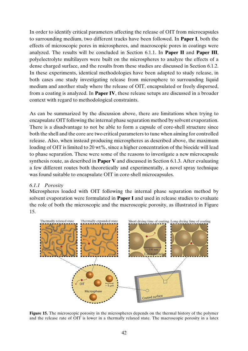
42
In order to identify critical parameters affecting the release of OIT from microcapsules to surrounding medium, two different tracks have been followed. In Paper I, both the effects of microscopic pores in microspheres, and macroscopic pores in coatings were analyzed. The results will be concluded in Section 6.1.1. In Paper II and Paper III, polyelectrolyte multilayers were built on the microspheres to analyze the effects of a dense charged surface, and the results from these studies are discussed in Section 6.1.2. In these experiments, identical methodologies have been adapted to study release, in both cases one study investigating release from microsphere to surrounding liquid medium and another study where the release of OIT, encapsulated or freely dispersed, from a coating is analyzed. In Paper IV, these release setups are discussed in a broader context with regard to methodological constraints. As can be summarized by the discussion above, there are limitations when trying to encapsulate OIT following the internal phase separation method by solvent evaporation. There is a disadvantage to not be able to form a capsule of core-shell structure since both the shell and the core are two critical parameters to tune when aiming for controlled release. Also, when instead producing microspheres as described above, the maximum loading of OIT is limited to 20 wt%, since a higher concentration of the biocide will lead to phase separation. These were some of the reasons to investigate a new microcapsule synthesis route, as described in Paper V and discussed in Section 6.1.3. After evaluating a few different routes both theoretically and experimentally, a novel spray technique was found suitable to encapsulate OIT in core-shell microcapsules.
6.1.1 Porosity Microspheres loaded with OIT following the internal phase separation method by solvent evaporation were formulated in Paper I and used in release studies to evaluate the role of both the microscopic and the macroscopic porosity, as illustrated in Figure 15.
Figure 15. The microscopic porosity in the microspheres depends on the thermal history of the polymer and the release rate of OIT is lower in a thermally relaxed state. The macroscopic porosity in a latex

43
coating depends on the drying time of the coating. When latex binder has merged together, after long drying time of the paint, a decrease in release rate of OIT occurs.
A main step in the internal phase separation method is the evaporation of the volatile solvent, DCM in this case, and the evaporation rate was found to affect the microscopic porosity. A thermally relaxed state of the microsphere polymer, PMMA, was achieved if evaporating DCM in an open beaker in fume hood over 24 hours (system here denoted F). This gave a more dense structure, or more specifically a decrease in free volume of PMMA. A thermally expanded state was achieved by accelerating the evaporation using a rotary evaporator (denoted R). It was clearly found that microspheres with polymers in a thermally relaxed state lowered the rate of OIT release, see Figure 16. The model-fitted diffusion coefficient of OIT is significantly larger for the rotary evaporated microspheres R compared to the microspheres F, see Table 3. Table 3. The calculation of size distribution, burst fraction and effective diffusion coefficient for OIT/PMMA microspheres F and R after release in aqueous suspension.
Microsphere type Mean radius (µm)
Burst fraction (pburst)
Diffusion coefficient (10-18 m2/s)
F 1.90 ± 0.02 0.09 ± 0.01 4.2 ± 0.4
R 1.89 ± 0.03 0.12 ± 0.01 10.4 ± 1.0
Figure 16. The suspension fractional release of OIT for three replica studies with slow evaporation of DCM (np¢) and three replica studies with fast evaporation of DCM (np¢). The left figure shows the entire release using a logarithmic time scale while the first 35 hours of the experiment are presented on a linear time scale in the right figure.
In order to strengthen these findings, heat treatment experiments were carried out using an autoclave. By using an autoclave, the microspheres could be treated in temperatures above their glass transition temperature, Tg, where the polymer chains can reshape and

44
conform in an energetically more stable microstructure as the temperature is slowly cooled below Tg. This was performed on suspensions R and F, respectively and the heat-treated suspensions were denoted RA and FA. The results strongly supported the findings above on the relationship between solvent method and microscopic porosity. The heat treatment of F microspheres did not alter the release pattern, see Figure 17. The R microspheres, on the other hand, were significantly modified in microscopic porosity by the heat treatment, as seen in Figure 18. Heat treatment at elevated temperature well above the glass-transition temperature thus proved to generate a relaxation pathway of the polymer chains to a more favorable and hence less porous state.
Figure 17. The suspension release of OIT for F (n) and heat-treated FA (u).

45
Figure 18. The suspension release of OIT for R (n) and heat-treated RA (u).
The effect of macroscopic porosity of the coating was investigated in Paper I by release studies of both freely and encapsulated OIT from waterborne varnish coatings, and the results can be found in Figure 19.
Figure 19. The release of OIT from varnish coatings. (A) The first 25 hours. (B) The entire experimental time. (t) Free OIT after 7 days drying with decay fitting (•••) and no-decay fitting (—). (l) Encapsulated OIT after 7 days drying with decay fitting (∙∙∙) and no-decay fitting (- - -). (t) Free OIT after 28 days drying with decay fitting (•••) and no-decay fitting (—). (l) Encapsulated OIT after 28 days drying with decay-fitting (∙∙∙) and no-decay fitting (- - -).
As can be noted in Figure 19, significant degradation of OIT occurs in the release medium of the coating studies after approximately 50 hours. No degradation was detected after the same experimental time during release of OIT in suspension. A few

46
possible reasons have been discussed. The analytical technique used to quantify OIT from coating release was HPLC chromatography with UV detection while release from microsphere suspension was analyzed using only UV/Vis spectrophotometry. Since HPLC separates ingoing components depending on its adsorption to chosen supporting material, it is highly sensitive to e.g. molecular structure or polarity. A decrease in detected concentration of OIT when analyzing the release from coatings indicates that degradation has occurred during the experiment. The conjugated part of the isothiazole ring might however still be intact since no degradation could be seen using UV/Vis spectrophotometer as analytical technique. Also, the aqueous environment differed between the two studies with respect to pH, light influence, and presence of other dissolved species, primarily from the coating. The mathematical models considering degradation used to fit the data samples are stated in Paper I and Section 4.4.2. Table 4. The results of calculation of effective diffusion coefficient, D, for OIT release from coatings at two different drying times.
The results show that encapsulated OIT releases slower than freely dispersed OIT from a varnish coating after 7 days of drying and the effective diffusion coefficients can be found in Table 4. Moreover, the drying time of the varnish influences the macroscopic structure of the coating and a longer drying time decreases the release rate and the effective OIT diffusion coefficient significantly. However, an opposite effect between free and encapsulated OIT was found after very long (28 days) drying time. Here the release rate was lower for the freely dispersed OIT compared to that of encapsulated OIT. A plausible explanation is the disruption of the merging close-packing of latex particles when microspheres were embedded in the coated film. The size of the latex particles is one order of magnitude smaller than the microspheres. This difference in length scales may affect the close-packing of the 28 days dried paint, see Figure 20, resulting in a structure not allowing for perfect homogenous film formation.
Formulation 7 days drying D
(10-16 m2/s) 28 days drying D
(10-16 m2/s)
Free OIT 307 ± 25 0.7 ± 0.1
Encapsulated OIT 163 ± 11 3.0 ± 0.4

47
Figure 20. The size of the microspheres may affect the close-packing of the smaller latex particles.
6.1.2 Polyelectrolyte Multilayers One way to tune a microsphere is to build polyelectrolyte multilayers (PEMs) at its surface, Figure 21, as investigated in Paper II and Paper III. This surface modification has been shown to result in a substantial decrease in release rate out from the microspheres. When adsorbing PEMs on top of the diblock copolymer the swollen polyelectrolyte block collapses. The conditions for assembly used in this work result in very dense PEM with rate-determining barrier capacity already at very thin thicknesses [89]. Two bilayers in this work will form an approximately 5-6 nm thin barrier which is sufficient to be rate-determining [93]. This can be compared to if using the non-ionic surfactant PVA as dispersant where a layer is approximately 20 nm thick and not rate-determining [73].
Figure 21. The layer-by-layer adsorption. The 600-b-4600 block-copolymer makes the microsphere surface highly negatively charged. When adsorbing polyelectrolyte multilayers on top of the block-copolymer the brush-like structure collapses and gives a dense structure. The hydrophobic biocide OIT will only solubilize in negligible low amounts in the multilayers.
The PEMs form a hydrophilic barrier at the surface of the microspheres, and its effect on the release out from the spheres has been investigated using two different active substances. In Paper II Disperse Red 13, a hydrophobic dye, was used in order to

48
evaluate the release while OIT was the chosen active substance in Paper III. OIT is almost 1000 times more hydrophilic than Disperse Red 13 in terms of water solubility, and a positive result for Disperse Red 13 might not lead to success when investigating OIT instead. The hydrophilic barrier of the PEM-modified microspheres will for instance affect the release of Disperse Red 13 to a larger extent, since the solubility of the active in the PEM layer is very low. This will affect Ki
A/B presented in Section 4.1. The more hydrophobic nature of Disperse Red 13 will also lower the burst release since the burst release is due to accumulation and saturation in the outermost part of the microparticle. The release of OIT from microspheres surface modified with PEMs to an aqueous suspension was compared to the release out from microspheres produced using PVA as emulsifier, and the results are found in Figure 22. It was observed that the PEM-layer decreased the effective diffusion coefficient 40 times, but the burst rate was unaltered. This can be compared with the two times reduction of thermally relaxed microspheres compared to microspheres with high microscopic porosity (see Section 6.1.1). The calculated effective diffusion coefficients can be found in Table 5.
Figure 22. The release of OIT from PVA-based (np) and PEM-modified (l¢) microspheres. Filled and unfilled symbols are duplicates. The left figure shows the first 25 hours on a linear scale while the entire release using a logarithmic time scale are showed in the right figure. Full and dashed lines are fitted diffusion models.
The PEM-modified and OIT loaded microspheres were mixed in a commercial water-borne and acrylic façade paint and the release of OIT out from the coating to the surrounding water reservoir was analyzed and compared to the results from freely dispersed OIT in the paint. Another parameter was in the same time considered: the drying time of the paint. The assumption, due to the results considering porosity in Paper I, was that the drying time of the paint is an important parameter that will affect the results. The main question was therefore if the drying time of the paint or the PEM

49
microspheres caused the structural feature with rate-determining diffusion properties in terms of release of OIT. The results are presented in Figure 23.
Figure 23. The fractional release m(t)/mtot of OIT from a latex paint as a function of time t. In left the first 300 hours of the experiment are displayed and the data has been fitted according to diffusion models. In right figure, the long-term release is displayed which includes the degradation of the biocide. Freely dispersed OIT is marked with n and p, and encapsulated OIT with p and r. Filled and unfilled symbols are duplicates. The different drying times are marked with, black (one day), blue (seven days) and red (33 days). The fitting for the curve corresponding to free OIT dried for one week was poor and has been excluded.
The release study was ongoing for 2000-3000 hours and it was clear that freely dispersed OIT in the coating was released faster than encapsulated OIT. Also, even if a longer drying time decreased the release rate for both free and encapsulated OIT, the effect is almost negligible for OIT encapsulated in PEM modified microspheres. Therefore, it was found in this study that the polyelectrolyte multilayers caused the rate-determining diffusion as the release rate was found to be more or less independent of the drying time of the paint. Another point of discussion is that it is rather impractical to dry a paint for one month in higher temperatures than room temperature and therefore is the results for one and seven days of drying time more interesting in an applied aspect. As in the case in Section 6.1.1 degradation was considered in the coating experiments but not in the suspension experiments. The reasons are the same as stated above.

50
Table 5. Calculated effective diffusion coefficients.
Microsphere type Diffusion coefficient
(10-18 m2/s)
OIT in unmodified microspheres 10.9 ± 0.3
OIT in PEM modified microspheres 0.28 ± 0.02
Formulation Drying time
(days)
Free OIT 1 107 ± 7 Encapsulated OIT 1 3.01 ± 0.08 Free OIT 7 (not evaluated) Encapsulated OIT 7 1.98 ± 0.04 Free OIT 33 0.15 ± 0.01 Encapsulated OIT 33 0.35 ± 0.03
6.1.3 Airbrush Pen Microcapsule Formation The chosen formulation route producing microcapsules using an airbrush pen is fast and straightforward. The end product is a microcapsule with titanium dioxide shell surrounding a core containing up to 50 wt% OIT. In order to confirm the core-shell structure of the formed microcapsules (in addition to visually inspection after centrifugation of the suspensions), NMR spectroscopy were used. Studies of the so-called principal recipe showed that the ratio OIT:oleyl alcohol remained the same in the microcapsules as in the initial oil phase. Also, by using UV/Vis spectrophotometry the encapsulation yield was investigated. The yield, defined as the fraction of OIT leaving the airbrush container that ends up in micron-sized core-shell particles, was found to be 35 %. This result was confirmed by NMR spectroscopy. As the synthesis path is novel, a great effort has been put in to tune and find a suitable recipe focusing on the ingoing components. As water phase, two different systems were investigated: pure water of MilliQ grade with and without the addition of poly(vinyl alcohol) (PVA). It was concluded that the addition of PVA had some benefits. First, and most importantly, PVA will stabilize the formed oil droplets which have a great impact on the end result. Where and exactly how the formation of microcapsules occurs has not been fully characterized so far but a hypothesis is that the formation starts immediately when the two phases entering the spray nozzle. The hydrolysis and subsequent condensation then occurs inside the nozzle but might also continue directly after leaving the nozzle. If this step is ongoing for a short while after leaving the nozzle, the result is relying on the stabilization of the oil droplets since the shape of the droplet will decide the shape of the prepared microcapsule. If instead using only MilliQ water as water phase, microcapsules were still formed, but to a large extent broken after a few weeks in

51
suspension, which could not be detected using PVA in the water phase. Micrographs showing produced microcapsules can be found in Figure 24.
Figure 24. A. Micrograph showing microcapsules loaded with 10 wt% OIT in oleyl alcohol, using 1 wt% PVA as water phase. B. Broken and fractured microcapsules showing the inner core released out to the surrounding. In this recipe, no PVA was used in the water phase. C. A larger broken capsule where the core-shell structure is visible. The scale bar is in all three cases corresponding to 10 µm.
Second, the surface activity of PVA provided a slightly narrower size distribution of the microcapsules and a lower mean average concerning the size, see Figure 25. It has been found that large capsules (>10 µm) break easily after formulation, therefore a narrow size distribution and a rather small microcapsule size are appreciated.
Figure 25. The size distribution of microcapsules using pure MilliQ water as water phase (l) or with the addition of PVA (n) fitted with a log normal distribution function.
The oil phase consisted of three main ingredients; a titania precursor, core material and in most cases the biocide OIT. Two different titania precursors were tested, titanium(IV) ethoxide and titanium(IV) butoxide. Due to the shorter chains in titanium(IV) ethoxide, this precursor reacts very fast when in contact with water, faster than the bulkier

52
titanium(IV) butoxide. As the setup is designed, the precursor should not react with the water until entering the spray nozzle to control the conformation of the outcome, micron-sized spherical capsules. Also, if the reaction occurs before entering the spray nozzle, the remaining oil phase are blocked. The formed titania will not pass the nozzle. Therefore, titanium(IV) butoxide was the preferred alternative when finding an optimal recipe, since titanium(IV) ethoxide reacts too fast and prior to the nozzle in this system. When investigating a suitable core material, different alkanes and alcohols were tested and it could be observed that this selection was crucial for the end result. By investigating 1-butanol, 1-hexanol, oleyl alcohol, dodecane and hexadecane, two main important properties were identified. Using hexadecane or oleyl alcohol as core material, a much larger number of microcapsules of core-shell structure were obtained as compared to using the other listed alternatives where the main issues were too fast reaction rates, formation of titania fragments and/or aggregates of large, broken capsules. Both hexadecane and oleyl alcohol are practically insoluble in water which then seems to be of importance. However, hexadecane was still not an ideal candidate. A large amount of the ingoing oil phase became microcapsules, in size of a few microns, but also larger aggregates and flakes of titania were formed. Instead, oleyl alcohol was shown to be by far the best suited core material in this setup. This oil phase using a longer fatty alcohol produced a high yield of microcapsules and the nozzle flow of oil phase and water phase, respectively, was not interrupted by the formation of titania in the interface between the two phases in an early stage of the experiment. The property of oleyl alcohol compared to hexadecane that may be beneficial in these experiments is its surface activity [94]. As touched upon above concerning the use of PVA in the water phase, a stabilization of the oil droplets in the excess of water phase seems to aid the formation of titania shell and enhance the result. Therefore, the use of oleyl alcohol may also be positive due to its surface activity. The ingoing components in the principal recipe are found in Chart 2.

53
Chart 2. The components of the principal recipe when following the airbrush pen microcapsule formation.
As mentioned earlier, OIT also shows surface-active properties and microcapsules consisting of only OIT as core material was investigated. However, a limitation could be found in the formation of the ingoing oil phase since OIT and titanium (IV) butoxide were found to be not completely miscible in the studied concentration range and pure OIT as core substance was therefore not an option. Instead, different mixtures of OIT and oleyl alcohol as core material were tested and it was found that 50 wt% of OIT was the maximum concentration still forming a homogeneous one-phase solution of the oil phase. The size distribution of different OIT/oleyl alcohol mixtures is presented in Figure 26.

54
Figure 26. The size distribution of microcapsules with 0 wt% OIT (n), 10 wt% OIT (l), 25% OIT (▲) and 50 wt% OIT (▼) encapsulated together with oleyl alcohol within a titania shell, fitted with a log normal distribution function.
It was concluded that microcapsules of core-shell structure loaded with up to 50 wt% OIT could be formed as compared to 20% for the polymeric counterparts discussed above. Also, the addition of OIT to the system produced microcapsules smaller in size, most probably aided by the surface-active properties of the biocide. The recipes with 10 wt% and 25 wt% OIT, respectively, showed high-quality yield of microcapsules, almost no aggregation formation, and a narrower size distribution of capsules than without addition of OIT, see Figure 26. A small fraction of the microcapsules loaded with 50 wt% OIT were not perfectly spherical in shape, showing similar problem as the polymeric microspheres loaded with 20 wt% OIT discussed earlier in this thesis. Also, microcapsules with 50 wt% OIT generated a small but noticeable tail of large, and therefore leaking, microcapsules. In addition, the importance of the propellant pressure (here N2) used in the setup was investigated. All systems described above were executed using 2.8 bar N2 as propellant and this value was chosen since it is the maximum pressure allowed for the spray nozzle. In addition, 1.4 bar, which is the lower limit for the spray nozzle, and 2.0 bar were tested. All three systems produced a high yield of microcapsules, but with noticeable differences. A nitrogen gas pressure of 1.4 bar generated a significant portion of large capsules (~10 µm) which broke early in the collected suspension, and aggregates of broken capsules and unreacted material were detected. Moreover, a significant amount of the reaction took place at an early stage in the airbrush pen. A noteworthy improvement was achieved when increasing the pressure to 2.0 bar, forming a larger number of microcapsules with more narrow size distribution. However, a nitrogen pressure using 2.8 bar was found as preferable. The high pressure produced the highest yield of microcapsules, a narrow size distribution and a setup with condensation of titania that did not initiate until reaching the spray nozzle.

55
As mention in the beginning of this section, the exact formation steps are not specified yet. If the condensation starts in the nozzle but the process does not conclude until in the air or even when collected as suspension, an interfacial stabilizer as PVA seems needed, which the study also indicates. A hypothesis is that a shell only starts to form around the oil droplet, at the interface to the water phase, inside the spray nozzle. In order for a complete shell to form, and not only fragments of titania at the interface, the system needs to be stabilized for some time after leaving the nozzle while unreacted precursor still in the oil droplet diffuse to the interface. Such process is then also most probably aided by a surface-active molecule in the oil phase, which we can conclude by the superior results using oleyl alcohol and OIT as core material.
6.2 ANTIMICROBIAL PROPERTIES In order to evaluate the antimicrobial properties of coatings containing freely or encapsulated OIT, the surface growth (or rather the lack thereof) of Aspergillus Niger was studied. Aspergillus Niger, also known as black mold, is a fungus and a common biofouler [95]. As mentioned in Section 2.2.2, the antimicrobial effect of a biocide-containing coating is determined by the surface concentration of the biocide, which in turn is decided by the surface flux. The antimicrobial effect of OIT was investigated in Paper III and the results will be summarized here. The coated plates used in the release studies described in Section 6.1.2 were removed from their water baths after a few months and put individually in petri dishes. 0.5 ml of Aspergillus Niger conidia suspension (~106 cfu/ml) was added onto the investigated samples containing freely dispersed or encapsulated OIT in the paint matrix, as well as blank samples used as references. Melted (~45 °C) malt extract agar (MEA) was poured into the petri dishes and the plates were incubated at 30 °C for three days after which the biofouling was assessed by visual inspection. The results can be found in Figure 27 where the surface flux is derived from the diffusion models found in Figure 23. Both freely dispersed and encapsulated OIT in coatings with three different drying times were visually inspected concerning surface growth of Aspergillus Niger, and the antifungal effects are listed in Table 6.

56
Table 6. The antifungal effect of the coatings and surface flux of OIT after 80–100 days of release with respect to OIT formulation and drying time of the paint.
Sample Drying time
(days) Flux
(10-2 µg/cm2/day) Antifungal effect
(%)
Free OIT 1 -0 0
Encapsulated OIT 1 2.9 0
Encapsulated OIT 7 6.9 85-90
Free OIT 33 6.0 0-5
Encapsulated OIT 33 9.2 ~95
It can be seen in Figure 27 that the surface flux differs between the samples with regard of coating drying time, biocide formulation and time elapse of biocide release. The flux decreases rapidly for the sample with one day of drying time and freely dispersed OIT in the coating, and the protection is lost already after approximately 10 days. This result can be connected to the findings concerning macroscopic porosity explained in Section 6.1.1. The sample with encapsulated OIT in paint dried for one day showed a significantly slower release rate. The two samples (freely dispersed and encapsulated OIT) corresponding to 33 days of drying have almost the same curvature but the sample with encapsulated OIT has a larger surface flux during a considerable majority of the measured interval, which subsequently should lead to higher surface concentration and superior surface protection. By visual inspection of the coated plates, it was clear that two of the plates had much better protection against the fungus compared to the other samples; both encapsulated OIT in coatings dried for 7 days and 33 days, respectively, displayed great antifungal effect. The remaining three plates had lower surface flux values and were full of microbial growth of the surfaces. These results correspond to the hypothesis that there is a critical surface flux for the system, represented by the grey horizontal line in Figure 27, and systems with a surface flux above the critical surface flux will then prevent biofouling.

57
Figure 27. Time-dependent OIT surface flux showing the antifouling effect for various coatings, with free or encapsulated OIT, visually provided by photographs showing the growth of Aspergillus niger. Freely dispersed OIT is marked with dashed lines, and encapsulated OIT with solid lines. The different drying times are marked with black (1 day), blue (7 days) and red (33 days). The grey horizontal line in the graph illustrates the critical surface flux needed to stay above the critical surface concentration and prevent fungal growth. Each image corresponds to the specific time when the fouling of Aspergillus niger was analysed for each coating. Coatings containing no OIT were used as blank reference for all drying times (not shown here).

58
59
7 CONCLUDING REMARKS In this work, several different microcapsule systems loaded with the biocide 2-n-octyl-4-isothiazolin-3-one (OIT) have been formulated and evaluated. Release of OIT have been analyzed from both microcapsules and coatings. The experimental design of the release methodology developed in this work is a robust and straightforward tool, suitable for many different systems. Polymeric microcapsules have been formulated using the internal phase separation method induced by solvent evaporation. The first approach was to produce core-shell microcapsules to be able to encapsulate the biocide OIT within a polymeric shell. Core-shell structured microcapsules can however only be formulated by the internal phase separation method if the shell polymer, the core material, and the aqueous phase all fulfill specific spreading conditions. It was concluded that incorporation of OIT in the system will prevent the core-shell formation due to surfactant-like properties. Instead polymeric microspheres loaded with OIT were produced and tuned in different ways. Both the microscopic porosity of the microsphere and the macroscopic porosity of the coating affect the release of OIT. It was shown that a thermally relaxed state of the polymeric microsphere will decrease the release rate significantly compared to a thermally expanded state. The macroscopic porosity in the chosen coating will also affect
7

60
the release rate and it was shown that the drying time greatly tune the diffusivity in the coating. By using a diblock copolymer as dispersant when formulating microspheres, polyelectrolyte multilayers can be built at the surface of the microsphere. This hydrophilic barrier has here been proven to significantly reduce the release rate of hydrophobic and semi-hydrophobic actives to the surrounding. It was also verified to be the rate-determining step, independent of the macroscopic porosity in paint. The antifouling properties of the biocide OIT were evaluated when both freely dispersed and encapsulated in coatings. When encapsulated and with drying times of the paint of one week or longer, the protection was still high enough to prevent biofouling after a few months immersed in water. This was not the case with the biocide freely dispersed in the paint. To be able to encapsulate OIT within an inorganic microcapsule of core-shell structure, a novel and fast approach was developed and evaluated. By using the airbrush pen technique, microcapsules with a hydrophilic titania shell surrounding a hydrophobic core consisting of up to 50 wt% OIT could be formed. In this setup, the addition of OIT gives the microcapsules a narrower size distribution.

61
8 ACKNOWLEDGEMENTS The Swedish Research Council Formas is acknowledged for financial support. I would also like to thank: My former examiner Magnus Nydén and my present examiner Anders Palmqvist, for giving me the opportunity to do research at TYK, and for all the support and encouragement. My main supervisor Lars Nordstierna. No one knows as much about both microcapsules and svensk lokalfotboll i sydöstra Sverige as you. Thank you for always being supportive and for all the discussions we have had about both work and others, it has been a true pleasure to work with you. My co-supervisor Markus Andersson Trojer for great guidance in the field of microencapsulation, and in the fine art of writing articles. My co-authors Alberta Mok, Helena Andersson, Ye Li, Krister Holmberg, Hermann Uhr, Hans Blanck and Björn Elgh, for support and fruitful discussions. My former diploma worker Lorenz Bock, for helping me in the project but also by challenging me with great questions. Good luck in your academic career. Thanks to exchange student Nancy Figueroa and all my former bachelor students, for your motivation in the project, and for giving me the opportunity to refine my teaching skills. Ann Jakobsson and Frida Andersson for all your help regarding almost anything, as invoices, sudden gift wrap issues and where to live in the Kungälv region. Thank you, Roger Forsberg, for help in getting chemicals, and to Kurt Löfgren for manufacturing polypropylene plates. My roomie Anand Kumar Rajasekharan. Thank you for not killing all the fishes and plants while I was away, even if you did a nice try. And thank you for being a great friend. Please remember me when you get the Nobel Prize. Hej boss! My new/old colleagues/friends at the diamond division, thanks for all the fun! Too much fika has been compensated by rough innebandy games, and summer courses have been a state of mind. I will truly miss you all.

62
All my friends outside doktorandbubblan, thank you for your love and also for sometimes making me think about other important things in life, as football, board games, and Weber. Finally, I would like to thank my family. The Familjen Borg, you are amazing and have always been, thanks for everything. To Lottie, for your endless love and patience. I am looking forward for whatever our next adventures together may bring! And Oliver, I love you so much.

63
9 REFERENCES 1. Shirakawa, M.A., R.G. Tavares, C.C. Gaylarde, M.E.S. Taqueda, K. Loh, and
V.M. John, Climate as the most important factor determining anti-fungal biocide performance in paint films. Science of the Total Environment, 2010. 408(23): p. 5878-5886.
2. Edge, M., N.S. Allen, D. Turner, J. Robinson, and K. Seal, The enhanced performance of biocidal additives in paints and coatings. Progress in Organic Coatings, 2001. 43(1-3): p. 10-17.
3. Bester, K. and X. Lamani, Determination of biocides as well as some biocide metabolites from facade run-off waters by solid phase extraction and high performance liquid chromatographic separation and tandem mass spectrometry detection. Journal of Chromatography A, 2010. 1217(32): p. 5204-5214.
4. Wittmer, I.K., R. Scheidegger, H.-P. Bader, H. Singer, and C. Stamm, Loss rates of urban biocides can exceed those of agricultural pesticides. Science of The Total Environment, 2011. 409(5): p. 920-932.
5. Coutu, S., C. Rota, L. Rossi, and D.A. Barry, Modelling city-scale facade leaching of biocide by rainfall. Water Research, 2012. 46(11): p. 3525-3534.
6. Coulthwaite, L., K. Bayley, C. Liauw, G. Craig, and J. Verran, The effect of free and encapsulated OIT on the biodeterioration of plasticised PVC during burial in soil for 20 months. International Biodeterioration & Biodegradation, 2005. 56(2): p. 86-93.
7. Wittmer, I.K., R. Scheidegger, C. Stamm, W. Gujer, and H.-P. Bader, Modelling biocide leaching from facades. Water Research, 2011. 45(11): p. 3453-3460.
8. Nordstierna, L., A.A. Abdalla, M. Nordin, and M. Nyden, Comparison of release behavior from microcapsules and microspheres. Prog. Org. Coat., 2010. 69(1): p. 49-51.
9. Nordstierna, L., A.A. Abdalla, M. Masuda, G. Skarnemark, and M. Nydén, Molecular release from painted surfaces: Free and encapsulated biocides. Progress in Organic Coatings, 2010. 69(1): p. 45-48.
10. Lu, Y.S. and R.C. Larock, New hybrid latexes from a soybean oil-based waterborne polyurethane and acrylics via emulsion polymerization. Biomacromolecules, 2007. 8(10): p. 3108-3114.
11. Weiss, K.D., Paint and coatings: A mature industry in transition. Progress in Polymer Science, 1997. 22(2): p. 203-245.
12. Talbert, R., Paint technology handbook. 2007, Boca Raton, FL, U.S.A.: Taylor & Francis Group.
13. Mariz, I.D.A., I.S. Millichamp, J.C. de la Cal, and J.R. Leiza, High performance water-borne paints with high volume solids based on bimodal latexes. Progress in Organic Coatings, 2010. 68(3): p. 225-233.
14. Stoye, D. and W. Freitag, eds. Paints, Coatings and Solvents. 2nd ed. 1998, Wiley-VCH.
15. Perera, D.Y., Effect of pigmentation on organic coating characteristics. Progress in Organic Coatings, 2004. 50(4): p. 247 - 262.
16. Kronberg, B., K. Holmberg, and B. Lindman, Surface Chemistry of Surfactants and Polymers. 2014, United Kingdom: John Wiley & Sons, Ltd.
17. Zhang, W., Z. Zhu, and C.Y. Cheng, A literature review of titanium metallurgical processes. Hydrometallurgy, 2011. 108(3–4): p. 177 - 188.

64
18. Prasai, B., B. Cai, M.K. Underwood, J.P. Lewis, and D.A. Drabold, Properties of amorphous and crystalline titanium dioxide from first principles. Journal of Materials Science, 2012. 47(21): p. 7515-7521.
19. Thiele, E.S. and R.H. French, Light-Scattering Properties of Representative, Morphological Rutile Titania Particles Studied Using a Finite-Element Method. Journal of the American Ceramic Society, 1998. 81(3): p. 469 - 479.
20. Fisher, J. and T.A. Egerton, Titanium Compunds, Inorganic, in Kirk-Othmer Encyclopedia of Chemical Technology. 2001, John Wliey & Sons, Inc.
21. Filippou, D. and G. Hudon, Iron removal and recovery in the titanium dioxide feedstock and pigment industries. JOM, 2009. 61(10): p. 36.
22. Elgh, N.B.E., Studies of Wet-Chemical Synthesis of Nanostructured Titanium Dioxide for Photocatalytic Applications. 2013, Göteborg: Instutionen för Kemi- och bioteknik, Chalmers tekniska högskola.
23. Livage, J., M. Henry, and C. Sanchez, Sol-gel chemistry of transition metal oxides. Progress in Solid State Chemistry, 1988. 18(4): p. 259- 341.
24. Scherer, G.W. and C.J. Brinker, Sol-Gel Science. 1990, London: Academic Press. 25. Siedenbiedel, F. and J.C. Tiller, Antimicrobial Polymers in Solution and on
Surfaces: Overview and Functional Principles. Polymers, 2012. 4(1): p. 46. 26. Nicolas, P. and A. Mor, Peptides as Weapons Against Microorganisms in the
Chemical Defense System of Vertebrates. Annual Review of Microbiology, 1995. 49: p. 277-304.
27. Nurioglu, A.G., A.C.C. Esteves, and G. de With, Non-toxic, non-biocide-release antifouling coatings based on molecular structure design for marine applications. 2015. 3(32): p. 6547 - 6570.
28. Arrhenius, Å., T. Backhaus, F. Grönvall, M. Junghans, M. Scholze, and H. Blanck, Effects of Three Antifouling Agents on Algal Communities and Algal Reproduction: Mixture Toxicity Studies with TBT, Irgarol, and Sea-Nine. Archives of Environmental Contamination and Toxicology, 2006. 50(3): p. 335-345.
29. Johansson, P., K.M. Eriksson, L. Axelsson, and H. Blanck, Effects of Seven Antifouling Compounds on Photosynthesis and Inorganic Carbon Use in Sugar Kelp Saccharina latissima (Linnaeus). Archives of Environmental Contamination and Toxicology, 2012. 63(3): p. 365-377.
30. Andersson Trojer, M., L. Nordstierna, J. Bergek, H. Blanck, K. Holmberg, and M. Nydén, Use of microcapsules as controlled release devices for coatings. Advances in Colloid and Interface Science, 2015. 222: p. 18-43.
31. Morley, J.O., A.J.O. Kapur, and M.H. Charlton, Structure-activity relationships in 3-isothiazolones. 2005. 3(20): p. 3713 - 3719.
32. Gillatt, J., Microbiological protection of waterborne paint formulations. Polymers Paint Colour Journal, 1993. 183(4328): p. 222-230.
33. Lewis D, H. and R. Cowsar D, Principles of Controlled Release Pesticides, in Controlled Release Pesticides. 1977, ACS. p. 1-16.
34. Thies, C., Microencapsulation, in Kirk-Othmer Encyclopedia of Chemical Technology. 2005, John Wiley & Sons, Inc.
35. Dubey, R., T.C. Shami, and K.U.B. Rao, Microencapsulation Technology and Applications. Defence Science Journal, 2009. 59(1): p. 82-95.
36. Barrett K. Green, L.S., Oil-containing Microscopic Capsules and Method of Making them, D. The National Cash Register Company, Ohio, Editor. 1957: USA.

65
37. Green, B.K., Oil-containing Microscopic Capsules and Method of Making them, D. The National Cash Register Company, Ohio, Editor. 1957: USA.
38. Skorb, E.V. and H. Möhwald, 25th Anniversary Article: Dynamic Interfaces for Responsive Encapsulation Systems. 2013. - 25(- 36): p. - 5043.
39. Chang, T.M.S., Semipermeable Microcapsules. Science, 1964. 146(3643): p. 524-525.
40. Trojer, M.A., Polymeric Core-Shell Particles: Physicochemical Properties and Controlled Release, in Encyclopedia of Chemical Technology, P. Somasundaran, Editor. 2013, Taylor and Francis: New York.
41. Parys, M.V., Smart Textiles Using Microencapsulation Technology, in Functional Coatings, S.K. Ghosh, Editor. 2006, Wiley-VCH: Weinheim. p. 221-258.
42. Ghosh, S.K., Functional Coatings and Microencapsulation: A General Perspective, in Functional Coatings, S.K. Ghosh, Editor. 2006, Wiley-VCH: Weinheim. p. 1-28.
43. Dai, C., B. Wang, and H. Zhao, Microencapsulation peptide and protein drugs delivery system. Colloids and Surfaces B: Biointerfaces, 2005. 41(2–3): p. 117 - 120.
44. Sinha, V.R. and A. Trehan, Biodegradable microspheres for protein delivery. Journal of Controlled Release, 2003. 90(3): p. 261-280.
45. Li, M., O. Rouaud, and D. Poncelet, Microencapsulation by solvent evaporation: State of the art for process engineering approaches. International Journal of Pharmaceutics, 2008. 363(1-2): p. 26-39.
46. Li, M.-H. and P. Keller, Stimuli-responsive polymer vesicles. Soft Matter, 2009. 5(5): p. 927-937.
47. Chen, W., F. Meng, R. Cheng, and Z. Zhong, pH-Sensitive degradable polymersomes for triggered release of anticancer drugs: A comparative study with micelles. Journal of Controlled Release, 2010. 142(1): p. 40-46.
48. Rijcken, C.J.F., O. Soga, W.E. Hennink, and C.F.v. Nostrum, Triggered destabilisation of polymeric micelles and vesicles by changing polymers polarity: An attractive tool for drug delivery. Journal of Controlled Release, 2007. 120(3): p. 131-148.
49. Li, Z.-Z., S.-A. Xu, L.-X. Wen, F. Liu, A.-Q. Liu, Q. Wang, H.-Y. Sun, W. Yu, and J.-F. Chen, Controlled release of avermectin from porous hollow silica nanoparticles: Influence of shell thickness on loading efficiency, UV-shielding property and release. Journal of Controlled Release, 2006. 111(1–2): p. 81-88.
50. Lopez, M.D., A. Maudhuit, M.J. Pascual-Villalobos, and D. Poncelet, Development of Formulations to Improve the Controlled-Release of Linalool to Be Applied As an Insecticide. Journal of Agricultural and Food Chemistry, 2012. 60(5): p. 1187 - 1192.
51. Çam, M., N.C. İçyer, and F. Erdoğan, Pomegranate peel phenolics: Microencapsulation, storage stability and potential ingredient for functional food development. LWT - Food Science and Technology, 2014. 55(1): p. 117-123.
52. Gharsallaoui, A., G. Roudaut, O. Chambin, A. Voilley, and R. Saurel, Applications of spray-drying in microencapsulation of food ingredients: An overview. Food Research International, 2007. 40(9): p. 1107-1121.
53. Nedovic, V., A. Kalusevic, V. Manojlovic, S. Levic, and B. Bugarski, An overview of encapsulation technologies for food applications. Procedia Food Science, 2011. 1(0): p. 1806-1815.

66
54. Teunou, E. and D. Poncelet, Batch and continuous fluid bed coating – review and state of the art. 2002. 53(4): p. 325 - 340.
55. Zydowicz, N., E. Nzimba-Ganyanad, and N. Zydowicz, PMMA microcapsules containing water-soluble dyes obtained by double emulsion/solvent evaporation technique. Polymer Bulletin, 2002. 47(5): p. 457-463.
56. Szabó, T., L. Molnár-Nagy, J. Bognár, L. Nyikos, and J. Telegdi, Self-healing microcapsules and slow release microspheres in paints. Progress in Organic Coatings, 2011. 72(1-2): p. 52-57.
57. Sørensen, G., A.L. Nielsen, M.M. Pedersen, S. Poulsen, H. Nissen, M. Poulsen, and S.D. Nygaard, Controlled release of biocide from silica microparticles in wood paint. Progress in Organic Coatings, 2010. 68(4): p. 299-306.
58. Trojer, M.A., L. Nordstierna, M. Nordin, M. Nyden, and K. Holmberg, Encapsulation of actives for sustained release. Physical Chemistry Chemical Physics, 2013. 15(41): p. 17727-17741.
59. Loxley, A. and B. Vincent, Preparation of poly(methyl methacrylate) microcapsules with liquid cores. Journal of Colloid Interface Science., 1998. 208(1): p. 49-62.
60. Torza, S. and S.G. Mason, Three-phase interactions in shear and electrical fields. Journal of Colloid and Interface Science, 1970. 33(1): p. 67-83.
61. Trongsatitkul, T. and B.M. Budhlall, Multicore-Shell PNIPAm-co-PEGMa Microcapsules for Cell Encapsulation. Langmuir, 2011. 27(22): p. 13468-13480.
62. Elgh, B. and A.E.C. Palmqvist, A facile low-temperature synthesis of TiO2 nanoparticles with excellent polymorph control. Journal of Sol-Gel Science and Technology, 2015. 76(2): p. 395-401.
63. Andersson, M., L. Österlund, S. Ljungström, and A. Palmqvist, Preparation of nanosize anatase and rutile TiO2 by hydrothermal treatment of microemulsions and their activity for photocatalytic wet oxidation of phenol. Journal of Physical Chemistry B, 2002. 106(41): p. 10674-10679.
64. Chou, T.C., T.R. Ling, M.C. Yang, and C.C. Liu, Micro and nano scale metal oxide hollow particles produced by spray precipitation in a liquid-liquid system. Materials Science and Engineering A-Structural Materials Properties Microstructure and Processing, 2003. 359(1-2): p. 24-30.
65. Iida, M., T. Sasaki, and M. Watanabe, Titanium dioxide hollow microspheres with an extremely thin shell. Chemistry of Materials, 1998. 10(12): p. 3780 - 3782.
66. Chai, L.X., X.D. Wang, and D.Z. Wu, Development of bifunctional microencapsulated phase change materials with crystalline titanium dioxide shell for latent-heat storage and photocatalytic effectiveness. Applied Energy, 2015. 138: p. 661-674.
67. Collins, A.M., C. Spickermann, and S. Mann, Synthesis of titania hollow microspheres using non-aqueous emulsions. Journal of Materials Chemistry, 2003. 13(5): p. 1112-1114.
68. Enejder, A., F. Svedberg, L. Nordstierna, and M. Nyden, Chemical release from single-PMMA microparticles monitored by CARS microscopy. Proc. SPIE, 2011. 7903(Multiphoton Microscopy in the Biomedical Sciences XI): p. 79030S/1-79030S/8.
69. Andersson Trojer, M., Y. Li, C. Abrahamsson, A. Mohamed, J. Eastoe, K. Holmberg, and M. Nyden, Charged microcapsules for controlled release of hydrophobic actives Part I: encapsulation methodology and interfacial properties. Soft Matter, 2013. 9(5): p. 1468-1477.

67
70. Decher, G., Fuzzy nanoassemblies: Toward layered polymeric multicomposites. Science, 1997. 277(5330): p. 1232-1237.
71. Joanny, J.F., Polyelectrolyte adsorption and charge inversion. European Physical Journal B, 1999. 9(1): p. 117-122.
72. G.J. Fleer, M.A.C.S., J.M.H.M. Scheutjens, T. Cosgrove, B. Vincent, Polymers at Interfaces. 1993, London: Chapman & Hall.
73. Dowding, P.J., R. Atkin, B. Vincent, and P. Bouillot, Oil CorePolymer Shell Microcapsules Prepared by Internal Phase Separation from Emulsion Droplets. I. Characterization and Release Rates for Microcapsules with Polystyrene Shells. Langmuir, 2004. 20(26): p. 11374-11379.
74. Stuart, M.A.C., G.J. Fleer, J. Lyklema, W. Norde, and J.M.H.M. Scheutjens, Adsorption of Ions, Polyelectrolytes and Proteins. Advances in Colloid and Interface Science, 1991. 34: p. 477-535.
75. K. Holmberg, B. Jönsson., B. Kronberg, B. Lindman, Surfactants and Polymers in Aqueous Solution. 2003, West Sussex, England: John Wiley & Sons Ltd.
76. Iler, R.K., Multilayers of Colloidal Particles. Journal of Colloid and Interface Science, 1966. 21(6): p. 569-&.
77. Kolasinska, M., R. Krastev, and P. Warszynski, Characteristics of polyelectrolyte multilayers: Effect of PEI anchoring layer and posttreatment after deposition. Journal of Colloid and Interface Science, 2007. 305(1): p. 46-56.
78. Caruso, F., R.A. Caruso, and H. Mohwald, Nanoengineering of inorganic and hybrid hollow spheres by colloidal templating. Science, 1998. 282(5391): p. 1111-1114.
79. Decher, G. and J.B. Schlenoff, Multilayer Thin Films: Sequential Assembly of Nanocomposite Materials. 2003, Weinhem: Wiley.
80. Strong, A.B., Plastics - Materials and Processing. Third ed. 2006, Upper Sadle River, New Jersey: Pearson Education.
81. Enejder, A., F. Svedberg, L. Nordstierna, and M. Nyden, Chemical Release from Single PMMA Microparticles Monitored by CARS microscopy. Multiphoton Microscopy in the Biomedical Sciences Xi, 2011. 7903.
82. Weiser, J.R. and W.M. Saltzman, Controlled Release for Local Delivery of Drugs: Barriers and Models. Journal of Controlled Release, (0).
83. Crank, J. and G.S. Park, Diffusion in Polymers. 1968, London: Academic Press. 84. Dowding, P.J., R. Atkin, B. Vincent, and P. Bouillot, Oil core-polymer shell
microcapsules prepared by internal phase separation from emulsion droplets. I. Characterization and release rates for microcapsules with polystyrene shells. Langmuir, 2004. 20(26): p. 11374-11379.
85. Dowding, P.J., R. Atkin, B. Vincent, and P. Bouillot, Oil core/polymer shell microcapsules by internal phase separation from emulsion droplets. ii: controlling the release profile of active molecules. Langmuir, 2005. 21(12): p. 5278-5284.
86. Romero-Cano, M.S. and B. Vincent, Controlled release of 4-nitroanisole from poly(lactic acid) nanoparticles. J. Controlled Release, 2002. 82(1): p. 127-135.
87. Standardization, E.C.f., Paints and varnishes - Laboratory method for determination of release of regulated dangerous substances from coatings in intermittent contact with water. 2011, CEN: Brussels.
88. Crank, J., The Mathematics of Diffusion. 2nd ed. 1975: Oxford University Press Inc.
89. Trojer, M.A., H. Andersson, Y. Li, J. Borg, K. Holmberg, M. Nyden, and L. Nordstierna, Charged microcapsules for controlled release of hydrophobic actives.

68
Part III: the effect of polyelectrolyte brush- and multilayers on sustained release. Physical Chemistry Chemical Physics, 2013. 15(17): p. 6456-6466.
90. Berry, J.D., M.J. Neeson, R.R. Dagastine, D.Y.C. Chan, and R.F. Tabor, Measurement of surface and interfacial tension using pendant drop tensiometry. Journal of Colloid and Interface Science, 2015. 454: p. 226 - 237.
91. Bock, L., PMMA Microspheres for Biocide Delivery, in Department of Chemistry and Molecular Biology. 2015, University of Gothenburg: Gothenburg.
92. Thomas, K.V. and S. Brooks, The environmental fate and effects of antifouling paint biocides. Biofouling, 2010. 26(1): p. 73 - 88.
93. Trojer, M.A., Y. Li, M. Wallin, K. Holmberg, and M. Nyden, Charged microcapsules for controlled release of hydrophobic actives Part II: Surface modification by LbL adsorption and lipid bilayer formation on properly anchored dispersant layers. Journal of Colloid and Interface Science, 2013. 409: p. 8-17.
94. Petermann, J., Der Einfluß monomolekularer Filme auf die Kinetik der Gasabsorption in wäßrige Lösungen. Berichte der Bunsengesellschaft für physikalische Chemie, 1977. 81(7): p. 649 - 656.
95. Adan, O.C.G. and R.A. Samson, Fundamentals of Mold Growth in Indoor Environments and Strategies for Healthy Living. 2011, Wageningen: Wageningen Academic Publishers.


![화학물질 화학제품 관리 강화대책 - Chemical Watchfiles.chemicalwatch.com/Biocide press release 31 Jan.pdf · [유통관리] 화학물질 유통채널별 맞춤형 관리](https://img.pdfslide.net/doc/110x75/608933366634b75b2e4289bb/e-oe-ee-eeoe-chemical-press-release-31-janpdf.jpg)