Embed Size (px)
Citation preview
UPTEC Q16 025
Examensarbete 30 hpDecember 2016
Evaluation of dry fly-ash particles causing difficult deposits for acoustic soot blowing of boilers
Arvid Bo Cedervall
Teknisk- naturvetenskaplig fakultet UTH-enheten Besöksadress: Ångströmlaboratoriet Lägerhyddsvägen 1 Hus 4, Plan 0 Postadress: Box 536 751 21 Uppsala Telefon: 018 – 471 30 03 Telefax: 018 – 471 30 00 Hemsida: http://www.teknat.uu.se/student
Abstract
Evaluation of dry fly-ash particles causing difficultdeposits for acoustic soot blowing of boilers
Arvid Bo Cedervall
This thesis compares ash collected from different boilers cleaned using infrasoundcleaning. The samples were evaluated from their physical properties, in an attempt tofind connections between the difficulty to remove ash and its physical appearance. Toget a deeper understanding of the mechanisms behind adhesion and fouling, andpossibly explain results from the study of the ash samples, a literature review wascarried out. The ash was also evaluated to see if any connections could be drawnbetween the physical properties of the ash and its fouling capabilities. A strongconnection was found between ash density and its fouling capabilities. It was foundthat no dry ash with a density higher than 0.4 g/ml were difficult to remove withinfrasound cleaning, and no ash with lower density was easy to remove. The ashdensity was calculated from a measurement of the weight of a certain volume of ashon a scale. Optical microscopy was used to study the ash samples, and gave anestimation of particle size, shape, and porosity. However, no clear connection couldbe observed with this method between the different samples and which were difficultto remove. The particle size for a few of the samples were also measured by a wetlaser sieving method, and while it does give a good picture of particle size, the sizewas not found to be a useful prediction of the ash fouling behaviour. The exactmechanism giving rise to the density dependence need to be further investigated.
ISSN: 1401-5773, UPTEC Q16 025Examinator: Åsa KassmanÄmnesgranskare: Urban WiklundHandledare: Martin Ellebro
Avlagringar i skorstenar
Arvid Bo Cedervall
Avlagringar i skorstenar, och vad man gör åt demNär ett bränsle brinner bildas det förutom värme och ljus även rök. Denna rök består av olika gaser, men kan även innehålla olika partiklar. Dessa partiklar kallas för flygaska, och kan komma både från eldstaden eller bildas i rökgasen. När röken kommer i kontakt med olika ytor i skorstenen kan det bildas avlagringar. Hur mycket avlagringar som bildas beror på många olika faktorer; bränsle, typ av eldstad, hur varm röken är, hur mycket partiklar som finns i röken, hur fuktig röken är samt utformningen av skorstenen.
Främsta skälet till att man vill göra rent i skorstenen är att man brukar ha värmeväxlare där. Ju mer avlagringar som fastnar på värmeväxlarna desto sämre effekt får de. Avlagringarna kan också skada både värmeväxlare och skorsten. Torr aska bildar oftast inte så mycket avlagringar i skorstenar, och de som bildas brukar vara lätta att avlägsna med infraljud. Det finns också ett stort antal andra metoder som kan ta bort avlagringar, med olika fördelar och nackdelar. Två vanliga metoder är att spruta ånga på avlagringarna eller att släppa metallkulor genom skorstenen.
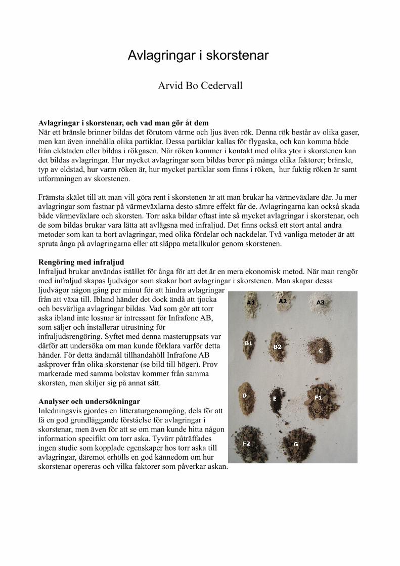
Rengöring med infraljudInfraljud brukar användas istället för ånga för att det är en mera ekonomisk metod. När man rengör med infraljud skapas ljudvågor som skakar bort avlagringar i skorstenen. Man skapar dessa ljudvågor någon gång per minut för att hindra avlagringarfrån att växa till. Ibland händer det dock ändå att tjockaoch besvärliga avlagringar bildas. Vad som gör att torraska ibland inte lossnar är intressant för Infrafone AB,som säljer och installerar utrustning förinfraljudsrengöring. Syftet med denna masteruppsats vardärför att undersöka om man kunde förklara varför dettahänder. För detta ändamål tillhandahöll Infrafone ABaskprover från olika skorstenar (se bild till höger). Provmarkerade med samma bokstav kommer från sammaskorsten, men skiljer sig på annat sätt.
Analyser och undersökningarInledningsvis gjordes en litteraturgenomgång, dels för attfå en god grundläggande förståelse för avlagringar iskorstenar, men även för att se om man kunde hitta någoninformation specifikt om torr aska. Tyvärr påträffadesingen studie som kopplade egenskaper hos torr aska tillavlagringar, däremot erhölls en god kännedom om hurskorstenar opereras och vilka faktorer som påverkar askan.
Undersökning av askproverna gjordes främst med mikroskop. Med det kunde närbilder tas av askan, vilket gjorde det lättare att jämföra de olika proverna. Främst studerades partikelstorlek och form, men man fick även en uppfattning om askans porositet. Några prover skickades för att analyseras med en metod som kallas lasersiktning. Det innebär att man blandar askan i en vätska och sedan lyser igenom vätskan med laser. En dator beräknar sedan partikelstorleken hos de olika partiklarna i vätskan. Även mängden av de olika partikelstorlekarna som förekom beräknas. Densiteten hos de olika askorna beräknades också från dess volym och vikt. Volymen aska erhölls genom att den placerades i en ask av en viss volym, varvid massa sedan vägdes med en våg.
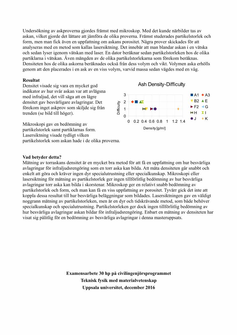
Resultat Densitet visade sig vara en mycket godindikator av hur svår askan var att avlägsnamed infraljud, det vill säga att en lägredensitet gav besvärligare avlagringar. Detförekom inget askprov som skiljde sig fråntrenden (se bild till höger).
Mikroskopi gav en bedömning avpartikelstorlek samt partiklarnas form.Lasersiktning visade tydligt vilkenpartikelstorlek som askan hade i de olika proverna.
Vad betyder detta?Mätning av torraskans densitet är en mycket bra metod för att få en uppfattning om hur besvärliga avlagringar för infraljudsrengöring som en torr aska kan bilda. Att mäta densiteten går snabbt och enkelt att göra och kräver ingen dyr specialutrustning eller specialkunskap. Mikroskopi eller lasersiktning för mätning av partikelstorlek ger ingen tillförlitlig bedömning av hur besvärliga avlagringar torr aska kan bilda i skorstenar. Mikroskop ger en relativt snabb bedömning av partikelstorlek och form, och man kan få en viss uppfattning av porositet. Tyvärr gick det inte att koppla dessa resultat till hur besvärliga beläggningar som bildades. Lasersiktningen gav en väldigt noggrann mätning av partikelstorleken, men är en dyr och tidskrävande metod, som både behöver specialkunskap och specialutrustning. Partikelstorleken ger dock ingen tillförlitlig bedömning av hur besvärliga avlagringar askan bildar för infraljudsrengöring. Enbart en mätning av densiteten har visat sig pålitlig för en bedömning av besvärliga avlagringar i denna masteruppsats.
Examensarbete 30 hp på civilingenjörsprogrammet
Teknisk fysik med materialvetenskap
Uppsala universitet, december 2016
0 0.2 0.4 0.6 0.8 1 1.2 1.40
1
2
3
Ash Density-Difficulty
A1 A3
B2 E
F2 G
H I
J K
Density [g/ml]
Diff
icu
lty
Table of Contents1. Introduction.....................................................................................................................................12. Background......................................................................................................................................3
2.1. Boiler overview...................................................................................................................43. Theory..............................................................................................................................................6
3.1. Fouling mechanisms...........................................................................................................73.2. Sooting methods..................................................................................................................9
4. Method...........................................................................................................................................114.1. Sample presentation..........................................................................................................124.2. Optical microscopy...........................................................................................................144.3. Laser sieving.....................................................................................................................144.4. Density..............................................................................................................................14
5. Results...........................................................................................................................................155.1. Physical behaviour............................................................................................................155.2. Optical Microscopy...........................................................................................................165.3. Laser Sieving.....................................................................................................................315.4. Density..............................................................................................................................32
6. Discussion......................................................................................................................................336.1. Microscopy........................................................................................................................336.2. Particle size.......................................................................................................................346.3. Density..............................................................................................................................34
7. Conclusions...................................................................................................................................378. Continuation..................................................................................................................................379. ACKNOWLEDGEMENT.............................................................................................................3810. Reference List..............................................................................................................................39

1. IntroductionThis thesis was commissioned by Infrafone AB, which is located in Stockholm, Sweden. They remove ash deposits in large industrial applications using an infrasound cleaning system. A typical installation can be seen in Figure 1. When predicting how successful an installation will be, it is often enough to look at the boiler type, fuel burned, and the temperature of the flue gas. However, this is not always the case. While there can exist both particles and droplets in the flue gas, the term "particle" in this area generally include both kinds. The same description will be used in this thesis.
Dry and friable soot is typically easy to remove and does not create problematic deposits, especiallynot in coal/oil boilers. Solid particles and fast-flowing flue gasses can have a blasting effect in the chimney and help reduce deposit formation. Acoustic cleaning can work very well to stop dry particles from settling on surfaces and diffuse into them. It can also make the deposits that do form, become looser and therefore easier to remove. It has less effect on wet particles, which stick harder to surfaces they impact, and porous deposits can be oscillated into harder dense deposits. (Skaardal)
The more ash there is in the flue gasses, the more problematic the cleaning of boilers typically becomes. This is true especially for ashes with compounds, which have low melting points. The ash itself can be molten, soft, or solid. Solid ash can still be both dry and wet. What makes solid ash wetis when other components condense on the surface. Here the solid particles act as nucleation points. When the ash is solid and dry, it seldom causes any problems with fouling. (Davidsson et al.)
It may be problematic to use acoustic cleaning with steam soot blowing. The acoustic cleaning requires dry soot to function well, and the added steam can condensate on the ash. When the acoustic cleaning system is operating, this can make them set harder together and become harder to remove, rather than shaking lose the particles. Acoustic cleaning works best when the temperature isbelow the melting point of the ash, but also above the dew point of the flue gas. (Skaardal)
Several studied mechanisms can make ash stick and form deposits. Among the most well studied mechanisms are thermophoresis and diffusiophoresis, which have more effect for small particles. For larger particles, impaction is a more significant effect. Finding out what effects are in place in a real world application can however prove difficult. If instead a connection could be found between the physical appearance of the ash and its ability to form deposits, it would make it easier to evaluate fouling behaviour. It is easy to find articles about phoresis effects in boilers, but significantly harder to find any studies, which connect them to dry ash fouling.
This thesis set out to find physical properties in the ash that could be used to predict what ash wouldbe difficult to remove. This was done by evaluating different ash samples that Infrafone AB had collected from various boilers. The ash samples were delivered personally from employees of Infrafone AB to the author. The focus was primarily set to look at particle size, shape, and porosity of the samples. This was done primarily with an optical microscope analysis, which was carried out in the MSL Cleanroom of the Ångström Laboratory in Uppsala, Sweden. The laser sieving was commissioned to the external company ALS Laboratory Group. Moreover, Infrafone AB performed the density measurements in their facilities.
In addition to the analysis, a literature study was included on different deposit formation mechanisms. This together with the ash sample analysis sought to increase the understanding about deposit growth and find a way to predict difficult ash.
1

Figure 1 – An installation of two infrasound cleaners in an industrial boiler. The infrasound cleaners are the blue vertical pipes and the connected cones. They stand fixed atop the economizer section of the boiler. Image by Infrafone AB
2
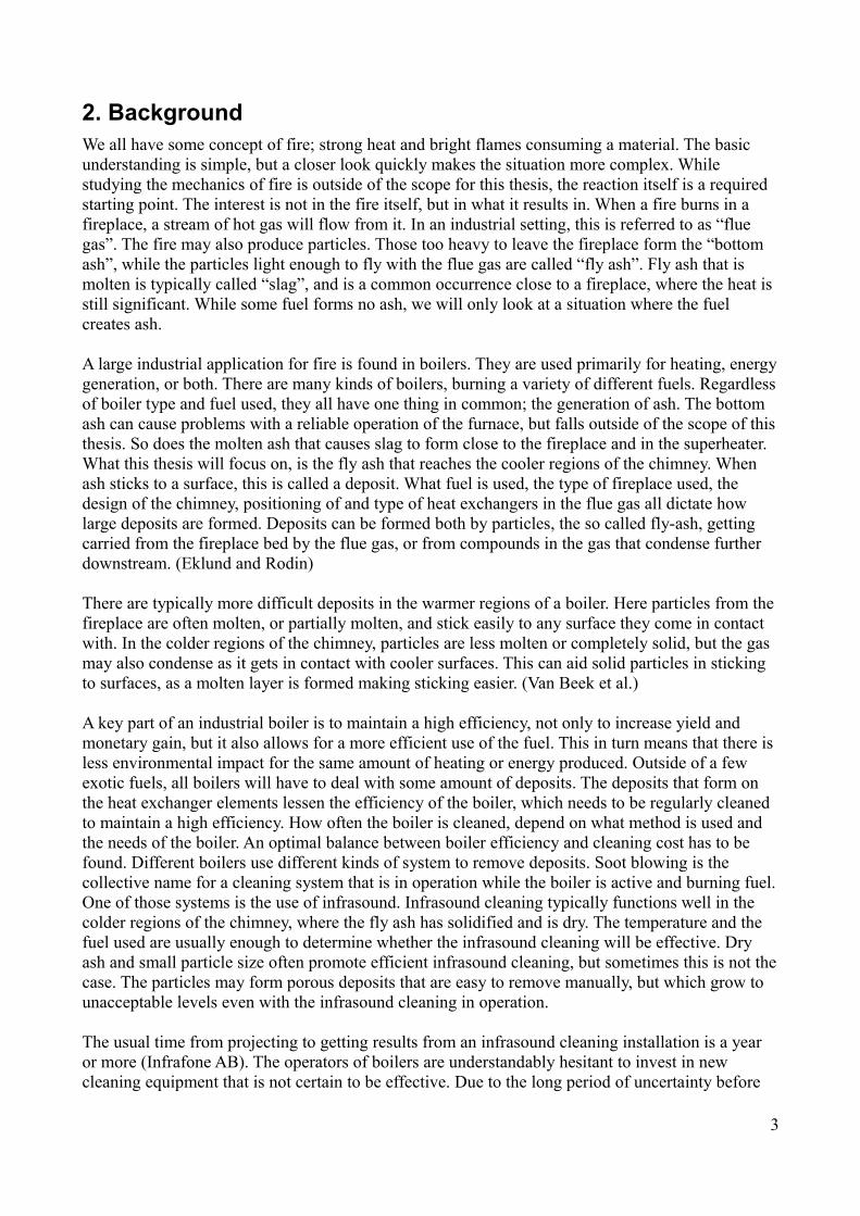
2. BackgroundWe all have some concept of fire; strong heat and bright flames consuming a material. The basic understanding is simple, but a closer look quickly makes the situation more complex. While studying the mechanics of fire is outside of the scope for this thesis, the reaction itself is a required starting point. The interest is not in the fire itself, but in what it results in. When a fire burns in a fireplace, a stream of hot gas will flow from it. In an industrial setting, this is referred to as “flue gas”. The fire may also produce particles. Those too heavy to leave the fireplace form the “bottom ash”, while the particles light enough to fly with the flue gas are called “fly ash”. Fly ash that is molten is typically called “slag”, and is a common occurrence close to a fireplace, where the heat is still significant. While some fuel forms no ash, we will only look at a situation where the fuel creates ash.
A large industrial application for fire is found in boilers. They are used primarily for heating, energygeneration, or both. There are many kinds of boilers, burning a variety of different fuels. Regardlessof boiler type and fuel used, they all have one thing in common; the generation of ash. The bottom ash can cause problems with a reliable operation of the furnace, but falls outside of the scope of thisthesis. So does the molten ash that causes slag to form close to the fireplace and in the superheater. What this thesis will focus on, is the fly ash that reaches the cooler regions of the chimney. When ash sticks to a surface, this is called a deposit. What fuel is used, the type of fireplace used, the design of the chimney, positioning of and type of heat exchangers in the flue gas all dictate how large deposits are formed. Deposits can be formed both by particles, the so called fly-ash, getting carried from the fireplace bed by the flue gas, or from compounds in the gas that condense further downstream. (Eklund and Rodin)
There are typically more difficult deposits in the warmer regions of a boiler. Here particles from the fireplace are often molten, or partially molten, and stick easily to any surface they come in contact with. In the colder regions of the chimney, particles are less molten or completely solid, but the gas may also condense as it gets in contact with cooler surfaces. This can aid solid particles in sticking to surfaces, as a molten layer is formed making sticking easier. (Van Beek et al.)
A key part of an industrial boiler is to maintain a high efficiency, not only to increase yield and monetary gain, but it also allows for a more efficient use of the fuel. This in turn means that there is less environmental impact for the same amount of heating or energy produced. Outside of a few exotic fuels, all boilers will have to deal with some amount of deposits. The deposits that form on the heat exchanger elements lessen the efficiency of the boiler, which needs to be regularly cleaned to maintain a high efficiency. How often the boiler is cleaned, depend on what method is used and the needs of the boiler. An optimal balance between boiler efficiency and cleaning cost has to be found. Different boilers use different kinds of system to remove deposits. Soot blowing is the collective name for a cleaning system that is in operation while the boiler is active and burning fuel.One of those systems is the use of infrasound. Infrasound cleaning typically functions well in the colder regions of the chimney, where the fly ash has solidified and is dry. The temperature and the fuel used are usually enough to determine whether the infrasound cleaning will be effective. Dry ash and small particle size often promote efficient infrasound cleaning, but sometimes this is not thecase. The particles may form porous deposits that are easy to remove manually, but which grow to unacceptable levels even with the infrasound cleaning in operation.
The usual time from projecting to getting results from an infrasound cleaning installation is a year or more (Infrafone AB). The operators of boilers are understandably hesitant to invest in new cleaning equipment that is not certain to be effective. Due to the long period of uncertainty before
3

knowing the success of an installation, it is of interest to find a method to evaluate what deposits areproblematic. The length of time to evaluate if an installation was sucessful or not further increase the need for a method which can predict which deposits will be difficult to remove.
2.1. Boiler overviewWhile this thesis is not about the function of boilers, nor about the best way to operate one, the setting for the thesis is inevitable within a boiler. Though the environment inside a boiler is very complex and will not be covered in detail, a basic understanding of a boiler is required to understand what can cause deposit formation and growth inside one.
The purpose of a boiler is to ignite a fuel, and from the combustion convert chemical energy to electricity or use the hot flue gas for heating. The fuel is burned in the fireplace. To burn the fuel, there needs to be a steady flow of air coming into the fireplace. As the fuel is burned, ash is produced by components of the fuel that have been combusted or which does not combust (Eklund and Rodin), (Strömberg and Svärd). Some the ash remains in the bed and need to be removed in time, either manually or automatically. These parts of the ash, along with ash that fall down in the bed again, form the bottom ash together with possible bed material (Strömberg and Svärd). The light particles will be carried with the flow of air as fly ash, and together with the gasses released from the fuel make up the flue gas (Strömberg and Svärd). The flue gas will leave the fireplace in a hot stream. Depending on boiler type, the maximum temperature of the flue gas can vary between 900-1600ºC (Livingston).
Figure 2 – Overview of the layout of a boiler. The exact layout differs from boiler to boiler. Image ofIdbäcken P3 as depiced in Figure 4 by Mann et al. (2014).
2.1.1. Radiant/First Draft
When the flue gas leaves the fireplace, it will enter the radiant section, also known as the first draft. Here most particles in the flue gas will be partially or fully molten. This makes the particles easy to
4
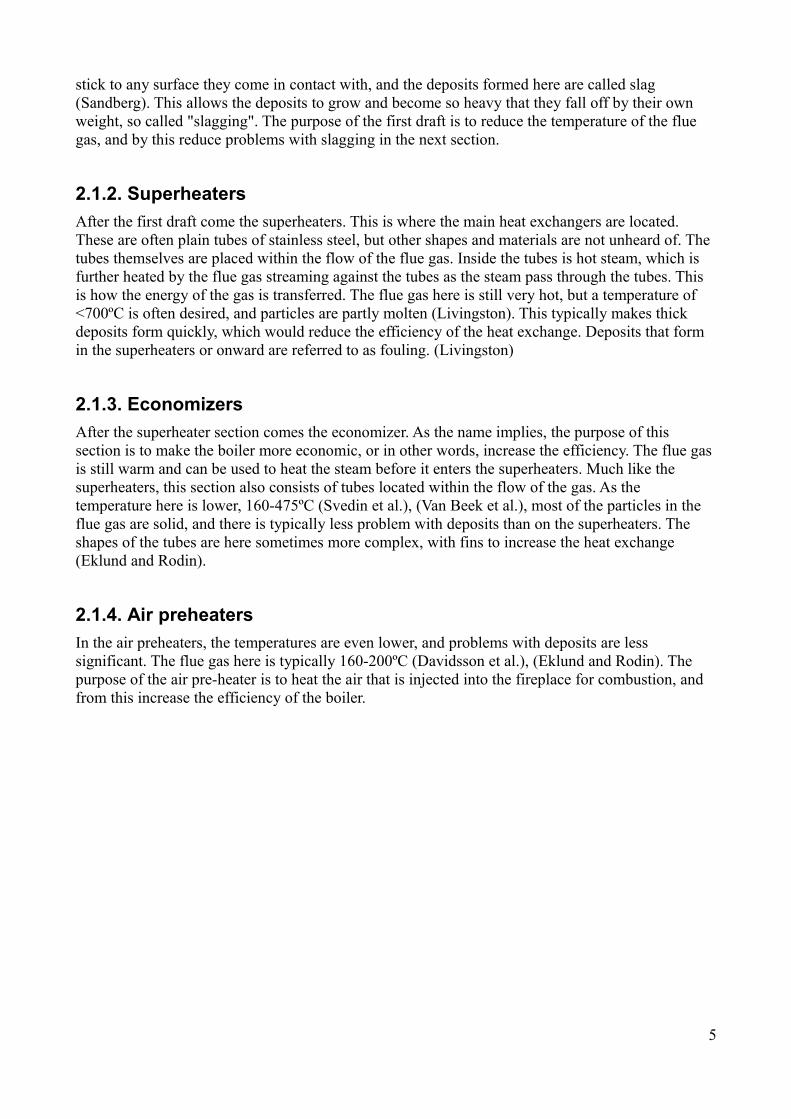
stick to any surface they come in contact with, and the deposits formed here are called slag (Sandberg). This allows the deposits to grow and become so heavy that they fall off by their own weight, so called "slagging". The purpose of the first draft is to reduce the temperature of the flue gas, and by this reduce problems with slagging in the next section.
2.1.2. Superheaters
After the first draft come the superheaters. This is where the main heat exchangers are located. These are often plain tubes of stainless steel, but other shapes and materials are not unheard of. The tubes themselves are placed within the flow of the flue gas. Inside the tubes is hot steam, which is further heated by the flue gas streaming against the tubes as the steam pass through the tubes. This is how the energy of the gas is transferred. The flue gas here is still very hot, but a temperature of <700ºC is often desired, and particles are partly molten (Livingston). This typically makes thick deposits form quickly, which would reduce the efficiency of the heat exchange. Deposits that form in the superheaters or onward are referred to as fouling. (Livingston)
2.1.3. Economizers
After the superheater section comes the economizer. As the name implies, the purpose of this section is to make the boiler more economic, or in other words, increase the efficiency. The flue gas is still warm and can be used to heat the steam before it enters the superheaters. Much like the superheaters, this section also consists of tubes located within the flow of the gas. As the temperature here is lower, 160-475ºC (Svedin et al.), (Van Beek et al.), most of the particles in the flue gas are solid, and there is typically less problem with deposits than on the superheaters. The shapes of the tubes are here sometimes more complex, with fins to increase the heat exchange (Eklund and Rodin).
2.1.4. Air preheaters
In the air preheaters, the temperatures are even lower, and problems with deposits are less significant. The flue gas here is typically 160-200ºC (Davidsson et al.), (Eklund and Rodin). The purpose of the air pre-heater is to heat the air that is injected into the fireplace for combustion, and from this increase the efficiency of the boiler.
5
3. TheoryThe normal gas flow has a typical velocity of several meters per second. When there are objects such as heat exchangers in the gas flow, it creates zones with higher and lower velocity. This happens in certain areas, such as behind tubes and close in front of them, as can be seen in Figure 4.Deposit growth is typically increased in areas with low flue gas velocity, particularly found in the wake of tubes (Bouris et al.), (Sandberg).
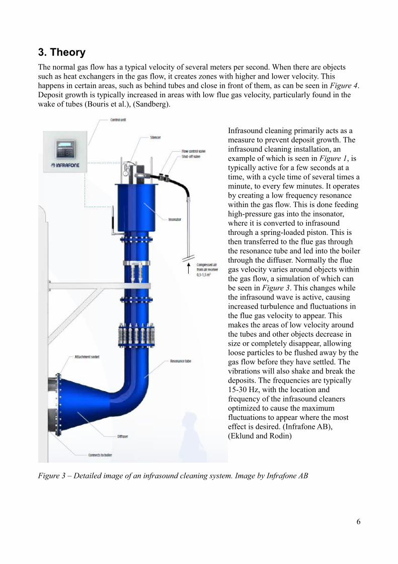
Infrasound cleaning primarily acts as a measure to prevent deposit growth. The infrasound cleaning installation, an example of which is seen in Figure 1, is typically active for a few seconds at a time, with a cycle time of several times aminute, to every few minutes. It operatesby creating a low frequency resonance within the gas flow. This is done feeding high-pressure gas into the insonator, where it is converted to infrasound through a spring-loaded piston. This is then transferred to the flue gas through the resonance tube and led into the boilerthrough the diffuser. Normally the flue gas velocity varies around objects withinthe gas flow, a simulation of which can be seen in Figure 3. This changes while the infrasound wave is active, causing increased turbulence and fluctuations in the flue gas velocity to appear. This makes the areas of low velocity around the tubes and other objects decrease in size or completely disappear, allowing loose particles to be flushed away by the gas flow before they have settled. The vibrations will also shake and break the deposits. The frequencies are typically 15-30 Hz, with the location and frequency of the infrasound cleaners optimized to cause the maximum fluctuations to appear where the most effect is desired. (Infrafone AB), (Eklund and Rodin)
Figure 3 – Detailed image of an infrasound cleaning system. Image by Infrafone AB
6
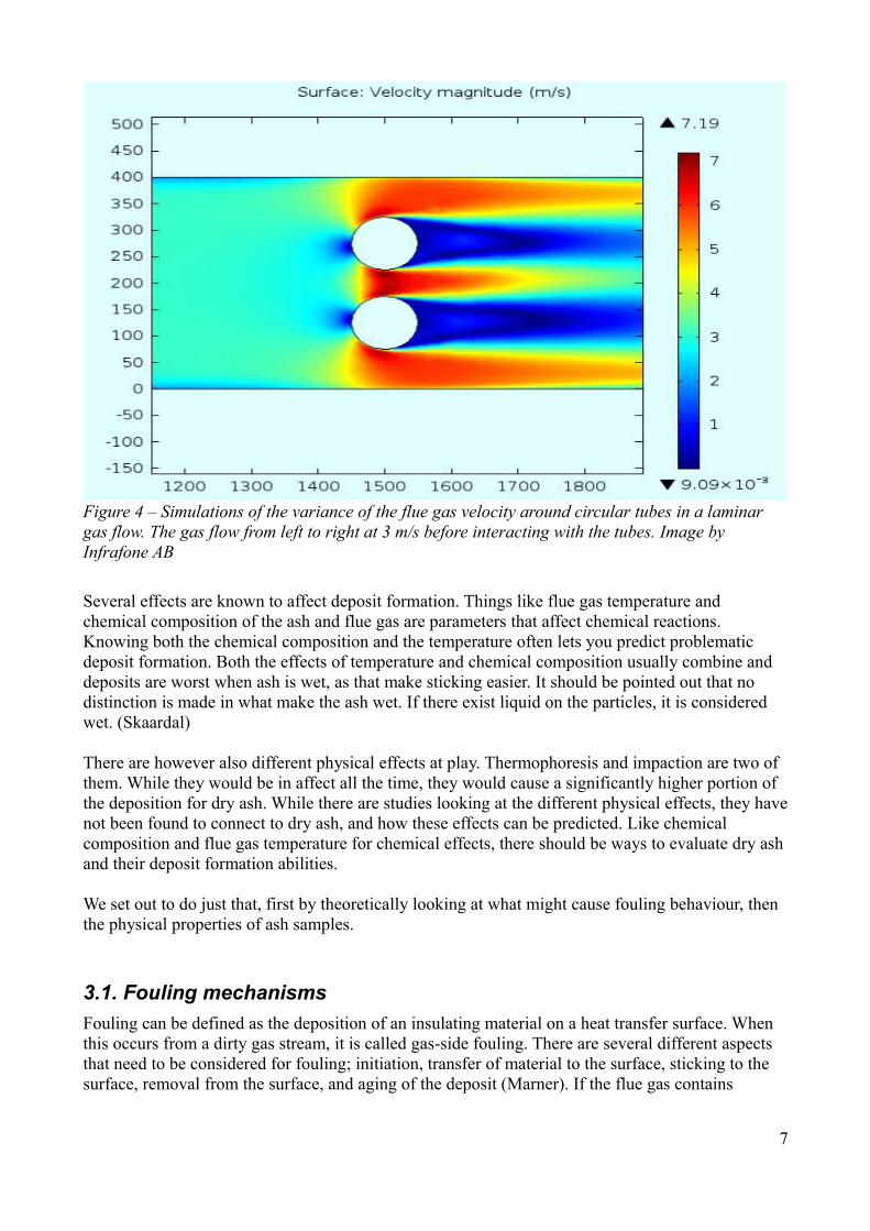
Figure 4 – Simulations of the variance of the flue gas velocity around circular tubes in a laminar gas flow. The gas flow from left to right at 3 m/s before interacting with the tubes. Image by Infrafone AB
Several effects are known to affect deposit formation. Things like flue gas temperature and chemical composition of the ash and flue gas are parameters that affect chemical reactions. Knowing both the chemical composition and the temperature often lets you predict problematic deposit formation. Both the effects of temperature and chemical composition usually combine and deposits are worst when ash is wet, as that make sticking easier. It should be pointed out that no distinction is made in what make the ash wet. If there exist liquid on the particles, it is considered wet. (Skaardal)
There are however also different physical effects at play. Thermophoresis and impaction are two of them. While they would be in affect all the time, they would cause a significantly higher portion of the deposition for dry ash. While there are studies looking at the different physical effects, they havenot been found to connect to dry ash, and how these effects can be predicted. Like chemical composition and flue gas temperature for chemical effects, there should be ways to evaluate dry ashand their deposit formation abilities.
We set out to do just that, first by theoretically looking at what might cause fouling behaviour, then the physical properties of ash samples.
3.1. Fouling mechanisms
Fouling can be defined as the deposition of an insulating material on a heat transfer surface. When this occurs from a dirty gas stream, it is called gas-side fouling. There are several different aspects that need to be considered for fouling; initiation, transfer of material to the surface, sticking to the surface, removal from the surface, and aging of the deposit (Marner). If the flue gas contains
7
nothing but inert gas for the temperature present, there will be no fouling. That would however be an exceptional case for a typical incinerator, as most of them already contain particles all the way from the bed. For a refuse waste incinerator, the particles typically found in the flue gas range from sub-micron to a few hundred microns large (van Beek et al.). This will be covered in more detail in the "transport" subsection below, which according to Marner (1996), are the most studied and the best understood mechanism. This still seems to hold true to this day. There can also form other components in the flue gas as it pass through the chimney, either from reactions within the flue gas itself or with materials found in the chimney. This will be covered in more detail in the Initiation subsection below. This section contains both chemical reactions and condensation of flue gas, whichmany articles covers and is probably the second most studied mechanism. So-called particulation, the deposition of particles onto a surface, is responsible for most of the deposited mass in boilers (Van Beek et al.). Sometimes different components are added to the fuel or bed material in an attempt to bind problematic compounds and hinder them from entering flue gas and cause problems, but this does not change the existence of the mechanism.
InitiationTo be able to form any kind of deposits, the gas must contain components that are solid or liquid, or which can form those components. Particles in the gas stream, whether solid or molten, can act as nucleation points and let other components stick to, or react with them. Components of the gas can react with other components of the gas, or objects within the gas stream, forming new compounds. (Sandberg). This section will cover how these interactions within the flue gas. Chemical reactions largely depend on the fuel used, is this supply the materials found within the flue gas. For this section, it is most important to look at reactive components in gas phase, as both solid and liquid phase components can already form deposits. The importance of chemical reactionscome from the ability of components of the gas to react, either with the material of the chimney or with the flue gas itself, and for the product to be in non-gas phase. If this reaction happens with the surface of a cooler tube or other part of the chimney, it can form a wet or solid deposit directly in contact with the surface, which will make it easier for further deposits to stick. If the reaction happens within the flue gas itself, different transport mechanisms need to be considered for the deposits to form. While different type of boilers can burn different kinds of fuels, ultimately it is thetemperature and fuels itself that is of significance for chemical reactions. Alkali metals, especially sodium and potassium, alongside chlorine, are predominant for problematic for deposit formation and corrosion (Davidsson et al.). Zinc, lead and titanium are also found to increase fouling and to cause corrosion (Enestam et al.). They do this by forming compounds with low melting points.Condensation is another important effect for initiating fouling. Condensation is initiated when the flue gas has cooled sufficiently to cause a gas-liquid phase transition for components in the gas. In the flue gas, already existing particles or droplets will act as nucleation points in the flue gas, and aid in the condensation of the gas. This can also occur locally against cooler surfaces such as heat exchangers or the chimney wall. This forms a wet layer on the affected surfaces, making further deposition easier. (Skaardal). While condensation can be problematic, its occurrence is easy to predict. Reviewing which compounds exist in the flue gas along with their condensation temperature, along with local temperatures of for example walls and heat exchangers, and that of the flue gas, give a good prediction of this behaviour. (Davidsson et al.)
TransferTransfer refers to the mechanics, which moves the particles within the flue gas into contact with parts of the chimney. As the gas move through the chimney, particles will tend to move with the flow of the gas. While the gas will flow around objects, the particles can collide or even be drawn tothem. The mechanisms for this are described below. The processes where particulate matters are deposited onto boiler surfaces are sometimes referred to as particulation (Van Beek et al.).
8

Impaction is the process where particles collide with deposition surfaces. This is the dominant deposit formation mechanism for larger particles (Abd-Elhady and Malayeri). This effect starts when particle size is roughly a few microns large (Van Beek et al.). It occurs when the gas flows around objects, but the inertia of the particles is too large to allow it to follow with the streamlines. Instead, they collide into the object (Marner). This will cause the particles to either bounce of or stick to the surface (Van Beek et al.). Whether the particles stick or not depends on several different factors, which are covered in the following subsection. (Konstandopoulos)Thermophoresis is an effect where particles move towards a colder surface, and is the primary contributor for deposition of smaller particles (Abd-Elhady and Malayeri). Particle sizes where this dominates are in the sub-micron to a few micron size range (Van Beek et al.). The thermophoretic effect occurs when there is a temperature gradient between a cooler surface and a warmer gas. This will create a force acting on the particles in the flue gas, directed towards the cooler surface. The thermophore tic force comes from the fact that molecules in a warmer gas will have a higher velocity then that of cooler gas, and from this, the gas on the warm side of a particle will hit the particle harder than the gas on the cooler side. This results in a net force acting towards the cooler surface. (Van Beek et al.). This effect is more dominant for smaller particles as they are more affected by collisions within the flue gas, allowing them to move more than larger particles.Diffusiophoresis is similar to thermophoresis in that it is dominant for smaller particles. However, instead of acting through a temperature gradient, it arises from a concentration gradient (Keh and Chen). The difference in concentration come from the fact that particles in the flue gas which are close to surface is captured and stick to the surface through different forces. When this happen, there will be fewer particles in the flue gas close to the surface than further away from it, which give rise to a concentration gradient.Electrophoresis is a well-known effect, where an external electrical field applies a force to a charged particle (Keh and Chen). While it is a well-known effect, it is only rarely described in a boiler environment. According to Harnevie et al. (2002), particles may attain an electrical charge from their velocity through the chimney. Exactly how the charge is generated is not understood, but it is often assumed that when a particle comes in contact to a surface, there may be a charge transfer.This is the most simple model, described as the "condenser model" (Matsusyama and Yamamoto). Experimental studies and simulations of electrostatic behaviour are typically done outside of a boiler environment, and cannot easily be translated to the behaviour within the flue gas (Keh and Chen), (Matsusyama and Yamamoto), (Zhang et al.).
StickingWhen the particles have been transported to the surface, they need to stick to the surface to cause fouling. This can occur either mechanically/electrostatically or from condensation (Eklund and Rodin). Smaller particles typically have low velocities when they are close to the surfaces, which allow most of them to stick to the surface (Abd-Elhady and Malayeri). Their low velocities arise from the fact that small particles usually can follow with the streamlines, and will then be captured in the wakes and vortices around tubes and other surfaces. Larger particles have less sticking probability due to their ability to bounce off (Van Beek et al.). Their ability to bounce largely arises from their larger inertia. This inertia make it harder for large particles to be captured in low speed regions, as they either collide with objects at high speed, with a high chance of bouncing of, or continue past the low speed regions with their higher momentum. The ability for particles to stick depends highly on deposits already present on the surface (Konstandopoulos), (Van Beek et al.), (Abd-Elhady and Malayeri). The presence of a liquid layer on the surface, or of the particles themselves, significantly increase sticking and deposit growth (Van Beek et al.). Sticking is also highly dependent on the roughness of the surface (Back et al.).While this is intuitive and well documented, it is not explained exactly why this is the case.
9
RemovalThe deposits are in a constant exposure to the flue gas. This creates a shear force against the particles in the deposit, which can cause some particles to loosen from the deposit and follow the flue gas. The shear forces act parallel to the surface, and can cause the particles to either roll or slideaway from their position on the deposit surface. It have been shown that the gas velocity required for rolling is much lower than that for dragging, and the former is therefore the most likely to occur of the two (Abd-Elhady and Malayeri). In addition to this, there are forces acting perpendicular to the surface that can remove deposits. These are lift, buoyancy and gravity (Abd-Elhady and Malayeri). Lift is not well explained and is on orders of magnitude smaller then buoyancy, and can be disregarded with no major difference in simulations (Sandberg). The buoyancy force comes fromthe differences in density between the particle and the gas (Sandberg). Gravity is the main contributor for large deposit removal. When deposits growth large enough, their weight can make large chunks fall off (Sandberg).
AgingDeposits that are allowed to remain for prolonged times allow for both thermal- and chemical sintering to take place. This can turn an initially porous deposit more compact and make it significantly harder to remove from the surface. The thermal and chemical sintering can also take place between the base material and the deposit, resulting in the formation of permanent deposits that are impossible to remove fully. As deposits grow, they usually become warmer on the surface, insulating the original cooler surface from the flue gas. This can cause the formation of a molten layer with accelerated growth from increased sticking. If the deposit does not grow heavy enough to break of, they can eventually an equilibrium can be reached where the deposit will no longer grow. This is reached when the temperature of the deposit surface is close to that of the flue gas, andthe removal rate from shear balance against the deposition rate. (Eklund and Rodin)
3.2. Sooting methods
There are as many different soot blowing solutions as there are industrial boilers. Each one will have its specific arrangement tailored to optimize the operation of its boiler. Different methods havedifferent strengths and weaknesses, and are used for different purposes. Some work well together, while others do not. Several hundreds of pages could easily be written about the different methods, but the most common ones are described briefly below.
Water soot blowing work by sending a high pressure stream of water towards the deposits. This is exclusively used against hard sintered deposits with a ceramic structure that are found before the superheater. The water can cause corrosion and is typically avoided on surfaces that are more sensitive. (Eklund and Rodin). When the water affects the hot surface, it rapidly heats up and evaporates. For deposits that are more porous, this can cause the deposit to crack and break as the water evaporates within the deposit. For more smooth deposits, the thermal shock the cold water causes can make the deposits contract and crack, causing them to fall off. In addition, this evaporating and rapidly expanding water can corrode tubes and limit their lifetime. While the method is highly effective, this behaviour makes it exclusively used only when absolutely required. Water soot blowing is either done manually by an opening a hatch in the chimney, or through fixed nozzles placed around the area. The volume of steam entering the flue gas during cleaning may require reducing the load of the boiler not to increase the pressure within the chimney.Steam soot blowing is the most widespread and used soot blowing method. It can generally describe as a friendlier version of water soot blowing. It can be used in both the superheater and the economizer (Eklund and Rodin). The steam is usually delivered through fixed or mobile beams. These beams stick in through the walls of the chimney, positioned to give balance between coverage
10

and cost. There are often rotating nozzles that distribute the steam around the beam. Since the steamcan mostly operate through line of sight, there are requirements for several beams to be placed through the boiler to keep the deposit removal sufficient. If there are droplets within the steam, this can cause corrosion or erosion on the tubes, reducing their lifespan (Eklund and Rodin), (Davidssonet al.). The steam used by the steam soot blowing is also taken from the boiler itself. This steam is normally used for electricity generation or heating, therefore the cost of operating the boiler is increased (Eklund and Rodin), (Davidsson et al.). The steam will also wet the flue gas, which may increase soot blowing requirements further in the chimney (Davidsson et al.), (Skaardal). This makes it less suitable to use alongside acoustic- and shot cleaning (Skaardal). Steam soot blowing isnormally performed every 6-18 hours (Eklund and Rodin).Shot cleaning is an installation, which operates by dropping balls or metal pieces, made of steel or aluminium, through the heat exchanger. The balls are dropped onto a plate above the heat exchanger, which make them scatter and bounce in different directions, to get a good spread of where they hit. Sometimes a cover has to be placed in front of the first tube row to protect them from the impact of the falling balls. When the balls hit the deposit, it will shake the tubes and may shatter the deposits, and make them fall off. It works best in the presence of thick and dry sintered deposits (Eklund and Rodin). After the balls or metal pieces have fallen through the heat exchanger,they are collected in the bottom. From there the balls or pieces are returned to the original position with the use of a mechanical or pneumatic system. There they will remain until they are dropped again and the process repeats. There are wear both on the balls and on the conveyer system, which will both require maintenance and regular replacing to keep operational. If the ash is wet, it can stick to the balls and clog the system for returning the balls to their original position (Skaardal). Theimpact of the balls may damage tubes. Shot cleaning can be done continuously or at set intervals, from one to several times a day (Eklund and Rodin), (Skaardal). Acoustic soot blowing can use either audible sound or infrasound. Both operate on the same principle, to cause resonance within the boiler. In the case of an audible cleaner, an opening is madein the side of the chimney, and a horn is fixed to it. When the horn is fed with high pressure air, it will cause resonance through the horn and cause the soundwave to travel into the flue gas. An infrasound cleaner work in a similar but more complex manner, by creating resonance within the flue gas itself. How infrasound-cleaning works has already been described above. The pressure from the sound, both audible and infrasound, cause oscillations of the flue gas velocity, which can prevent thick deposits from forming (Eklund and Rodin). They do so both by shaking and breaking deposits and by flushing away loose particles. Acoustic soot blowing works best with dry ash, as theoscillations may make wet ash settle in denser and harder to remove deposits (Skaardal). This also means that it is most suited for the boiler regions where the temperature is above the dew point of the flue gas, but below the melting point of the particles (Skaardal). Infrasound has a longer reach, but requires a much larger and more extensive installation than audible soot blowing (Eklund and Rodin). Acoustic soot blowing is typically done more than once a minute, to every few minutes (Davidsson et al.), (Infrafone AB). While audible soot blowing can be heard, infrasound soot blowing can usually not be. However, it can cause resonance and vibrations in other objects, thus still produce audible noise.Explosion soot blowing can be compared to the acoustic soot blowing methods. It works triggeringa controlled explosion within the chimney. Instead of causing prolonged sonic exposure, it instead causes a single shockwave. This can be done manually by inserting a device through a hatch in the side of the chimney. Often a "balloon" of a gas mixture is ignited, causing the explosion. It has proven effective against most kinds of deposits, but this method is usually only used when thick sintered deposits have formed (Eklund and Rodin). This can also be automated and used continuously to keep deposits from growing. When automated, a device is installed in a similar manner to the audible soot blowing horn. Instead of causing a resonant wave, however, the explosive gas mixture is fed into a chamber, where it is ignited. From there, the shockwave is
11
guided into the chimney through a horn-like structure. The intervals for these are often a few times an hour (Davidsson et al.). The vibrations caused by the shockwave may damage the boiler, but is usually not the case (Eklund and Rodin). Hammer soot blowing (rapping) use large hammers or other heavy objects to frequently strike objects that need cleaning. Pneumatic or mechanical hammers are installed on the outside of the chimney. Reinforcement plates are placed where they are positioned to prevent them from damaging the wall. When they strike the plate, vibrations will spread through the chimney, causing walls and heat exchangers to shake. These vibrations will then crack brittle deposits (Eklund and Rodin). Rapping is often used frequently, but will cause a lot of noise around the boiler. It may also damage the boiler, such as causing bolts to loosen or even snap (Davidsson et al.). Not only does this cause extra maintenance from workers checking and tightening bolts, but also the hammers themselves often require frequent maintenance.
12
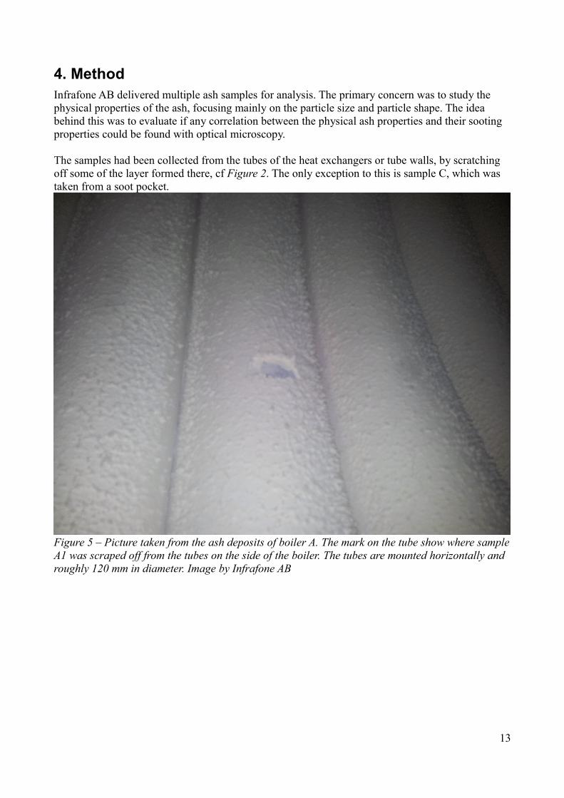
4. MethodInfrafone AB delivered multiple ash samples for analysis. The primary concern was to study the physical properties of the ash, focusing mainly on the particle size and particle shape. The idea behind this was to evaluate if any correlation between the physical ash properties and their sooting properties could be found with optical microscopy.
The samples had been collected from the tubes of the heat exchangers or tube walls, by scratching off some of the layer formed there, cf Figure 2. The only exception to this is sample C, which was taken from a soot pocket.
Figure 5 – Picture taken from the ash deposits of boiler A. The mark on the tube show where sampleA1 was scraped off from the tubes on the side of the boiler. The tubes are mounted horizontally and roughly 120 mm in diameter. Image by Infrafone AB
13
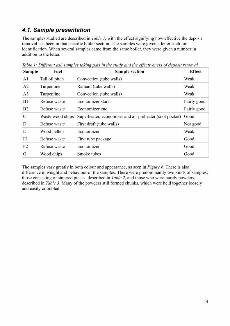
4.1. Sample presentationThe samples studied are described in Table 1, with the effect signifying how effective the deposit removal has been in that specific boiler section. The samples were given a letter each for identification. When several samples came from the same boiler, they were given a number in addition to the letter.
Table 1: Different ash samples taking part in the study and the effectiveness of deposit removal. Sample Fuel Sample section Effect
A1 Tall oil pitch Convection (tube walls) Weak
A2 Turpentine Radiant (tube walls) Weak
A3 Turpentine Convection (tube walls) Weak
B1 Refuse waste Economizer start Fairly good
B2 Refuse waste Economizer end Fairly good
C Waste wood chips Superheater, economizer and air preheater (soot pocket) Good
D Refuse waste First draft (tube walls) Not good
E Wood pellets Economizer Weak
F1 Refuse waste First tube package Good
F2 Refuse waste Economizer Good
G Wood chips Smoke tubes Good
The samples vary greatly in both colour and appearance, as seen in Figure 6. There is also difference in weight and behaviour of the samples. There were predominantly two kinds of samples;those consisting of sintered pieces, described in Table 2, and those who were purely powders, described in Table 3. Many of the powders still formed chunks, which were held together loosely and easily crumbled.
14
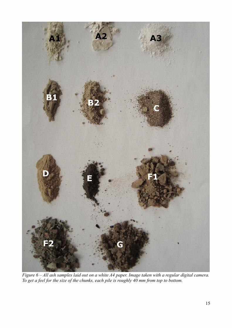
Figure 6 – All ash samples laid out on a white A4 paper. Image taken with a regular digital camera.To get a feel for the size of the chunks, each pile is roughly 40 mm from top to bottom.
15
4.2. Optical microscopy
To get a closer look at the ash samples, they were studied with an optical microscope. This was done with the Olympus AX70 Research Microscope in Ångström Microstructure Laboratory (MSL). To do this, each ash sample was placed in a plastic petri dish with a spatula. The petri dish was then placed on the hold of the Olympus AX70 microscope and illuminated from the top. Different settings was tried to evaluate which gave most information. Once good contrast and focus had been found, a picture was taken with the attached CCD camera, and saved with the Picsara image software it is connected to.
4.3. Laser sieving
A few selected ash samples were sent to ALS Laboratory Group. They perform a grain size analysis using a wet sieve analysis method using laser diffraction. The particles are suspended in a liquid andthe size fraction evaluated by using laser diffraction. This is done by letting a laser beam shine through the liquid, and from the diffraction pattern calculates the size of the suspended particles. For the fraction >63 μm a wet mesh sieving method was used. Fractions smaller then this was analysed by a laser particle size analyser using liquid dispersion mode. This was done according to ISO 11277:2009. From this a measurement of the particle size, a distribution was acquired, and with+/- 10% error margin a confidence of about 95% is achieved.
4.4. Density
Martin Ellebro (Infrafone AB) performed density measurements. The ash was put into a box containing roughly 30 ml, and then weighted on a scale. From this the density was calculated, and isshown in Table 5.
16
5. Results
5.1. Physical behaviour
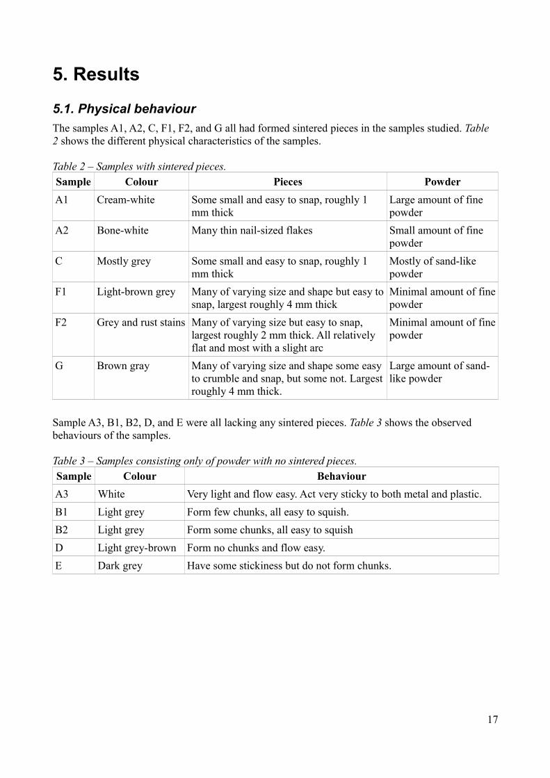
The samples A1, A2, C, F1, F2, and G all had formed sintered pieces in the samples studied. Table 2 shows the different physical characteristics of the samples.
Table 2 – Samples with sintered pieces.Sample Colour Pieces Powder
A1 Cream-white Some small and easy to snap, roughly 1 mm thick
Large amount of fine powder
A2 Bone-white Many thin nail-sized flakes Small amount of fine powder
C Mostly grey Some small and easy to snap, roughly 1 mm thick
Mostly of sand-like powder
F1 Light-brown grey Many of varying size and shape but easy tosnap, largest roughly 4 mm thick
Minimal amount of finepowder
F2 Grey and rust stains Many of varying size but easy to snap, largest roughly 2 mm thick. All relatively flat and most with a slight arc
Minimal amount of finepowder
G Brown gray Many of varying size and shape some easyto crumble and snap, but some not. Largestroughly 4 mm thick.
Large amount of sand-like powder
Sample A3, B1, B2, D, and E were all lacking any sintered pieces. Table 3 shows the observed behaviours of the samples.
Table 3 – Samples consisting only of powder with no sintered pieces.Sample Colour Behaviour
A3 White Very light and flow easy. Act very sticky to both metal and plastic.
B1 Light grey Form few chunks, all easy to squish.
B2 Light grey Form some chunks, all easy to squish
D Light grey-brown Form no chunks and flow easy.
E Dark grey Have some stickiness but do not form chunks.
17

5.2. Optical Microscopy
This section shows the appearance of the samples as seen through a microscope. All the samples had large difference in height. The inability to image all particles in focus is not only caused by uneven samples, as the agglomerations of particles of the samples were larger than the depth of focus of the microscope. This is typically seen in the images by sections of small areas being in focus surrounded by unfocused ones, or the other way around.
Boiler A
Boiler A was originally fired with Tall oil pitch (A1). It was later changed to use turpentine (A2 & A3) as fuel. Ash samples were taken both before and after this change.
A1 – Tall oil pitch from the convection section
In Figure 7 The ash particles are similar in colour through the sample. The ash seem to aggregate into larger clusters composing of smaller particles. The particles appear small, the majority being <50 μm in size and their shape is uneven. The clusters fall apart to touch, but the bonds are strong enough to form clusters that do not fall apart from gravity alone.
Figure 7 – Fine powder from the convection section tube walls of a tall oil pitch fired boiler.
18
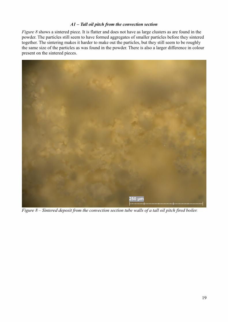
A1 – Tall oil pitch from the convection section
Figure 8 shows a sintered piece. It is flatter and does not have as large clusters as are found in the powder. The particles still seem to have formed aggregates of smaller particles before they sintered together. The sintering makes it harder to make out the particles, but they still seem to be roughly the same size of the particles as was found in the powder. There is also a larger difference in colour present on the sintered pieces.
Figure 8 – Sintered deposit from the convection section tube walls of a tall oil pitch fired boiler.
19
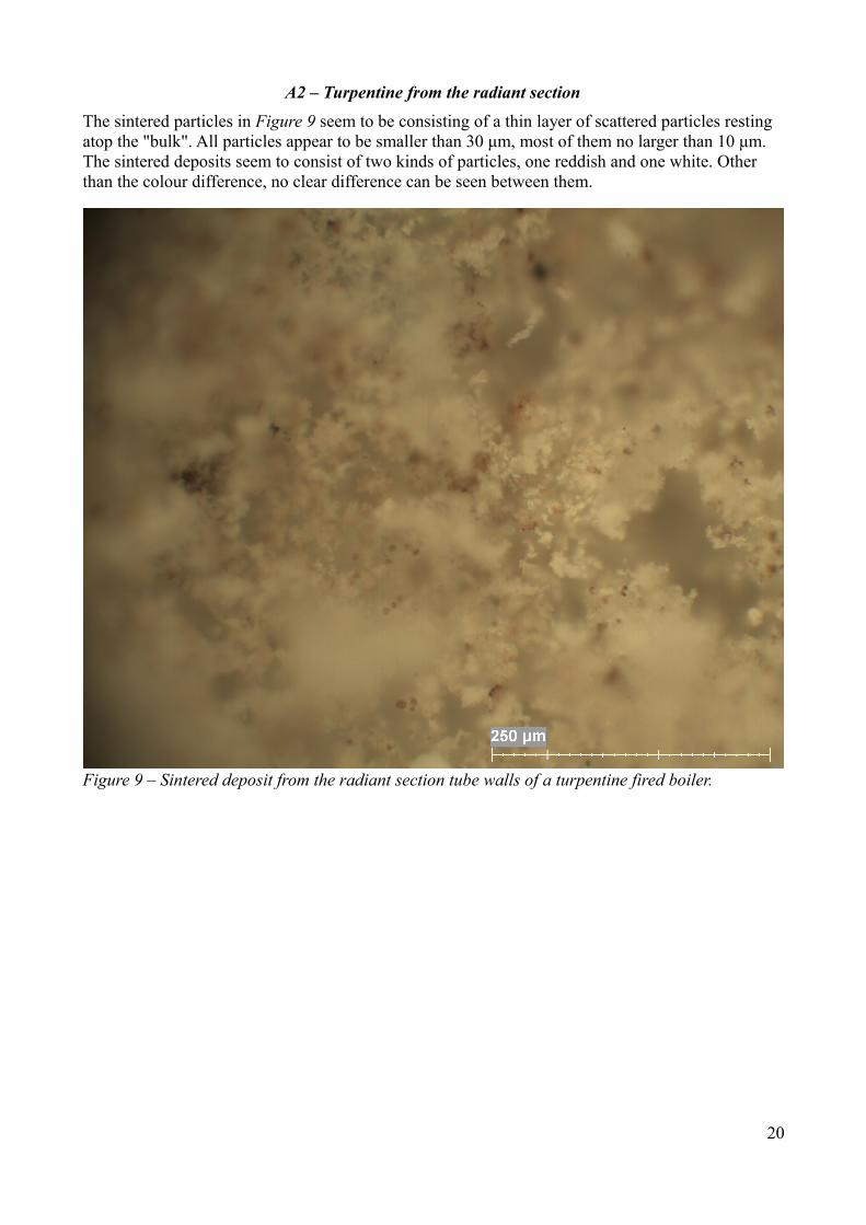
A2 – Turpentine from the radiant section
The sintered particles in Figure 9 seem to be consisting of a thin layer of scattered particles resting atop the "bulk". All particles appear to be smaller than 30 μm, most of them no larger than 10 μm. The sintered deposits seem to consist of two kinds of particles, one reddish and one white. Other than the colour difference, no clear difference can be seen between them.
Figure 9 – Sintered deposit from the radiant section tube walls of a turpentine fired boiler.
20
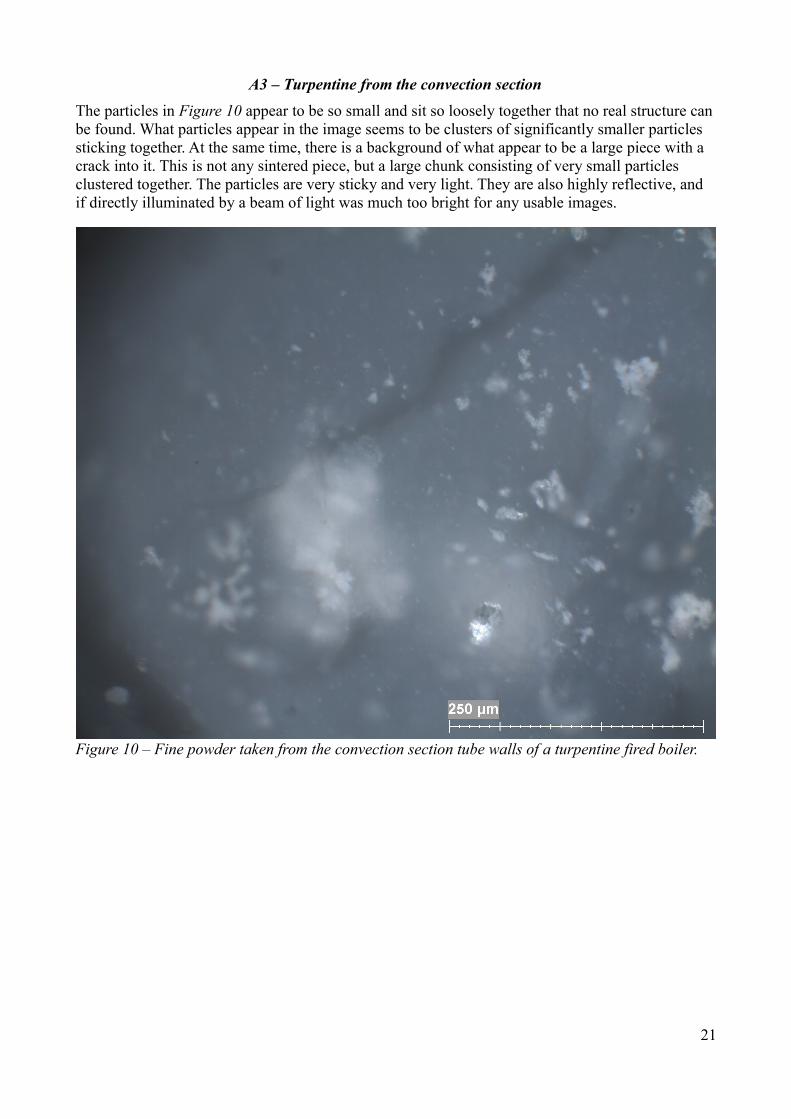
A3 – Turpentine from the convection section
The particles in Figure 10 appear to be so small and sit so loosely together that no real structure canbe found. What particles appear in the image seems to be clusters of significantly smaller particles sticking together. At the same time, there is a background of what appear to be a large piece with a crack into it. This is not any sintered piece, but a large chunk consisting of very small particles clustered together. The particles are very sticky and very light. They are also highly reflective, and if directly illuminated by a beam of light was much too bright for any usable images.
Figure 10 – Fine powder taken from the convection section tube walls of a turpentine fired boiler.
21
Boiler B
Boiler B is fired by Refuse waste, with ash samples taken from the start (B1) and end (B2) of the economizer.
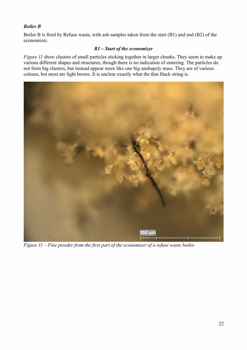
B1 – Start of the economizer
Figure 11 show clusters of small particles sticking together in larger chunks. They seem to make up various different shapes and structures, though there is no indication of sintering. The particles do not form big clusters, but instead appear more like one big unshapely mass. They are of various colours, but most are light brown. It is unclear exactly what the thin black string is.
Figure 11 – Fine powder from the first part of the economizer of a refuse waste boiler.
22

B2 – End of the economizer
The particles in Figure 12 seem to be of similar sizes, though they differ in colour. No individual particle seems to be larger than 10-20 μm, though the clusters they aggregate in are slightly larger. Compared to Figure 11, the shapes of the clusters are less diverse and simpler in their appearance.
Figure 12 – Fine powder from the last part of the economizer of a refuse waste fired boiler.
23
Boiler C
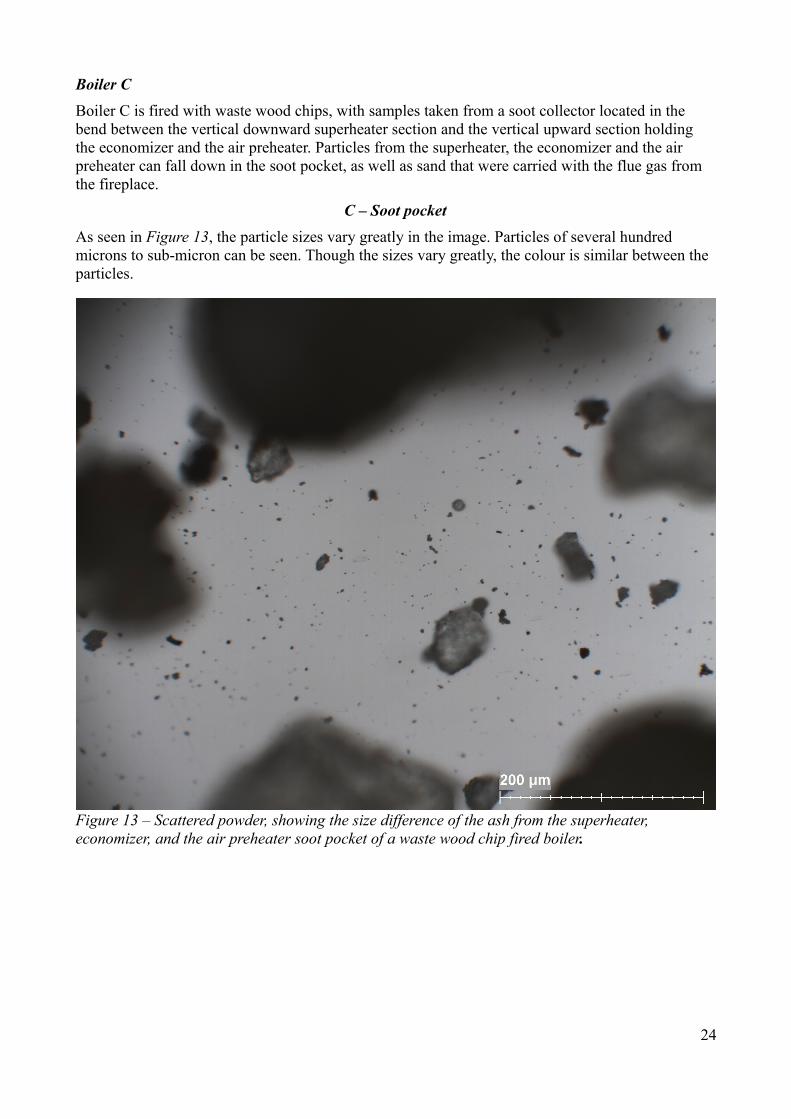
Boiler C is fired with waste wood chips, with samples taken from a soot collector located in the bend between the vertical downward superheater section and the vertical upward section holding the economizer and the air preheater. Particles from the superheater, the economizer and the air preheater can fall down in the soot pocket, as well as sand that were carried with the flue gas from the fireplace.
C – Soot pocket
As seen in Figure 13, the particle sizes vary greatly in the image. Particles of several hundred microns to sub-micron can be seen. Though the sizes vary greatly, the colour is similar between the particles.
Figure 13 – Scattered powder, showing the size difference of the ash from the superheater, economizer, and the air preheater soot pocket of a waste wood chip fired boiler.
24
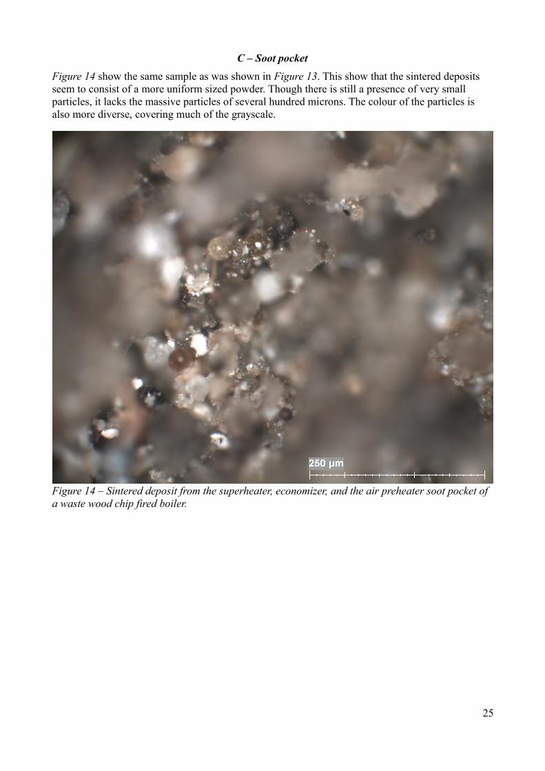
C – Soot pocket
Figure 14 show the same sample as was shown in Figure 13. This show that the sintered deposits seem to consist of a more uniform sized powder. Though there is still a presence of very small particles, it lacks the massive particles of several hundred microns. The colour of the particles is also more diverse, covering much of the grayscale.
Figure 14 – Sintered deposit from the superheater, economizer, and the air preheater soot pocket of a waste wood chip fired boiler.
25

Boiler D
Boiler D is fired with refuse waste, with ash samples taken from the first draft tube walls.
D – First draft
Most of the particles in Figure 15 appear very small and having aggregated into clusters. Their colour is overall very similar between the particles, though a few differ from the others. The most notable thing to note is that some of the larger particles seem to be partially opaque and darker in colour.
Figure 15 – Fine powder from the first draft tube walls of a refuse waste fired boiler.
26

Boiler E
Boiler E is fired with wood pellets, with ash samples taken from the economizer.
E – Economizer
The particles in Figure 16 vary a bit more in sizes than most of the powder samples. The particles seem to range from 30 μm down to sub-micron range. The particles seem to form a network more than clusters, consisting of ridges of particles more than chunks. There is also great variety in the colours of the particles, though they do not seem connected to any particular particle shape or size.
Figure 16 – Fine powder from the economizer of a wood pellet fired boiler.
27
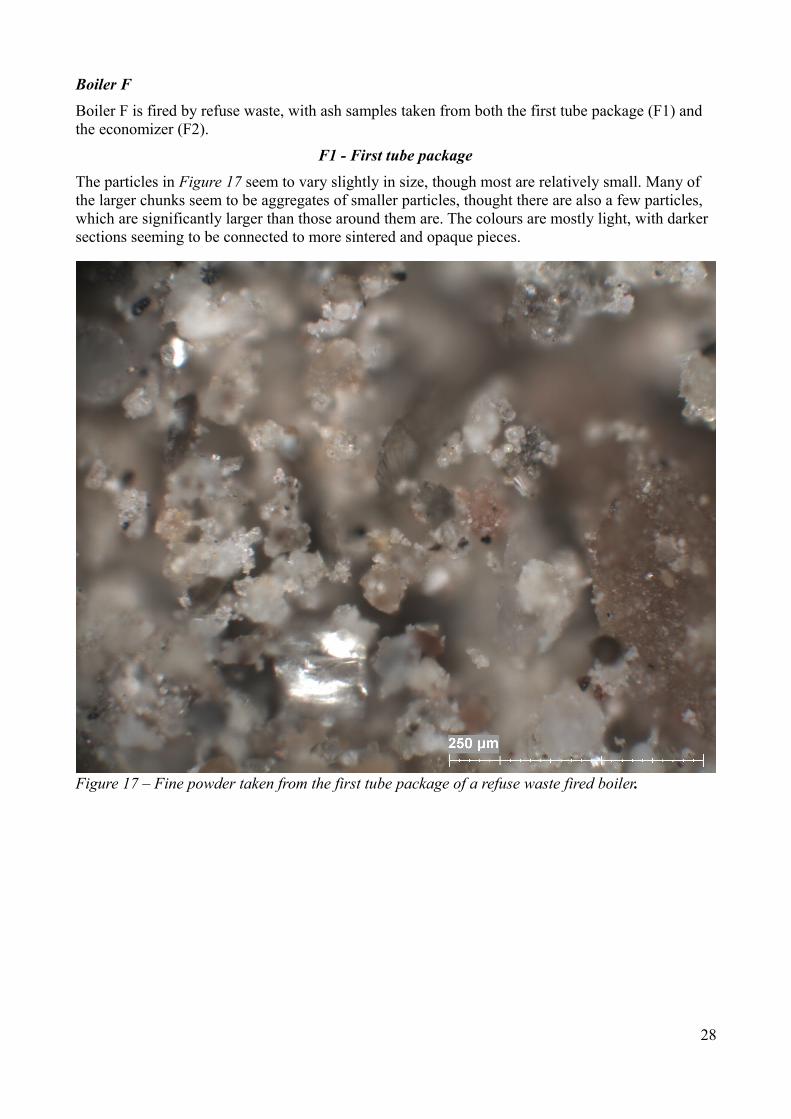
Boiler F
Boiler F is fired by refuse waste, with ash samples taken from both the first tube package (F1) and the economizer (F2).
F1 - First tube package
The particles in Figure 17 seem to vary slightly in size, though most are relatively small. Many of the larger chunks seem to be aggregates of smaller particles, thought there are also a few particles, which are significantly larger than those around them are. The colours are mostly light, with darker sections seeming to be connected to more sintered and opaque pieces.
Figure 17 – Fine powder taken from the first tube package of a refuse waste fired boiler.
28

F1 - First tube package
In Figure 18, the particles are fairly even in size. There are no particles massively larger than the others are. There seem to be ridges formed on the surface of the sintered piece from these particles. There appear to be a more solid structure, which the ridges rest atop, with no large porosities found. The colours of the particles vary but are predominantly of the greyscale.
Figure 18 – Sintered deposit from the first tube package of a refuse waste fired boiler.
29
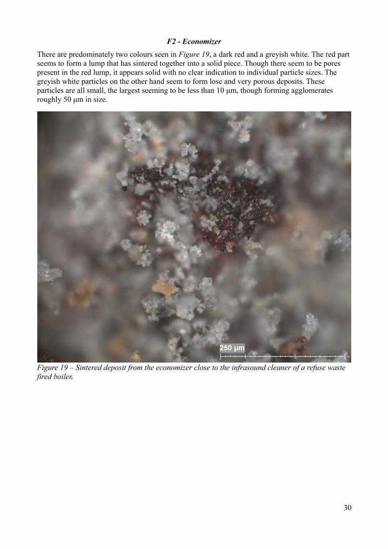
F2 - Economizer
There are predominately two colours seen in Figure 19, a dark red and a greyish white. The red partseems to form a lump that has sintered together into a solid piece. Though there seem to be pores present in the red lump, it appears solid with no clear indication to individual particle sizes. The greyish white particles on the other hand seem to form lose and very porous deposits. These particles are all small, the largest seeming to be less than 10 μm, though forming agglomerates roughly 50 μm in size.
Figure 19 – Sintered deposit from the economizer close to the infrasound cleaner of a refuse waste fired boiler.
30
F2 - Economizer
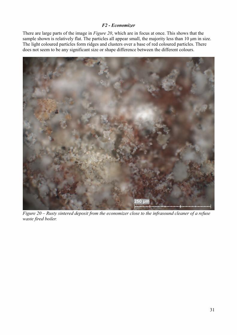
There are large parts of the image in Figure 20, which are in focus at once. This shows that the sample shown is relatively flat. The particles all appear small, the majority less than 10 μm in size. The light coloured particles form ridges and clusters over a base of red coloured particles. There does not seem to be any significant size or shape difference between the different colours.
Figure 20 – Rusty sintered deposit from the economizer close to the infrasound cleaner of a refuse waste fired boiler.
31
Boiler G
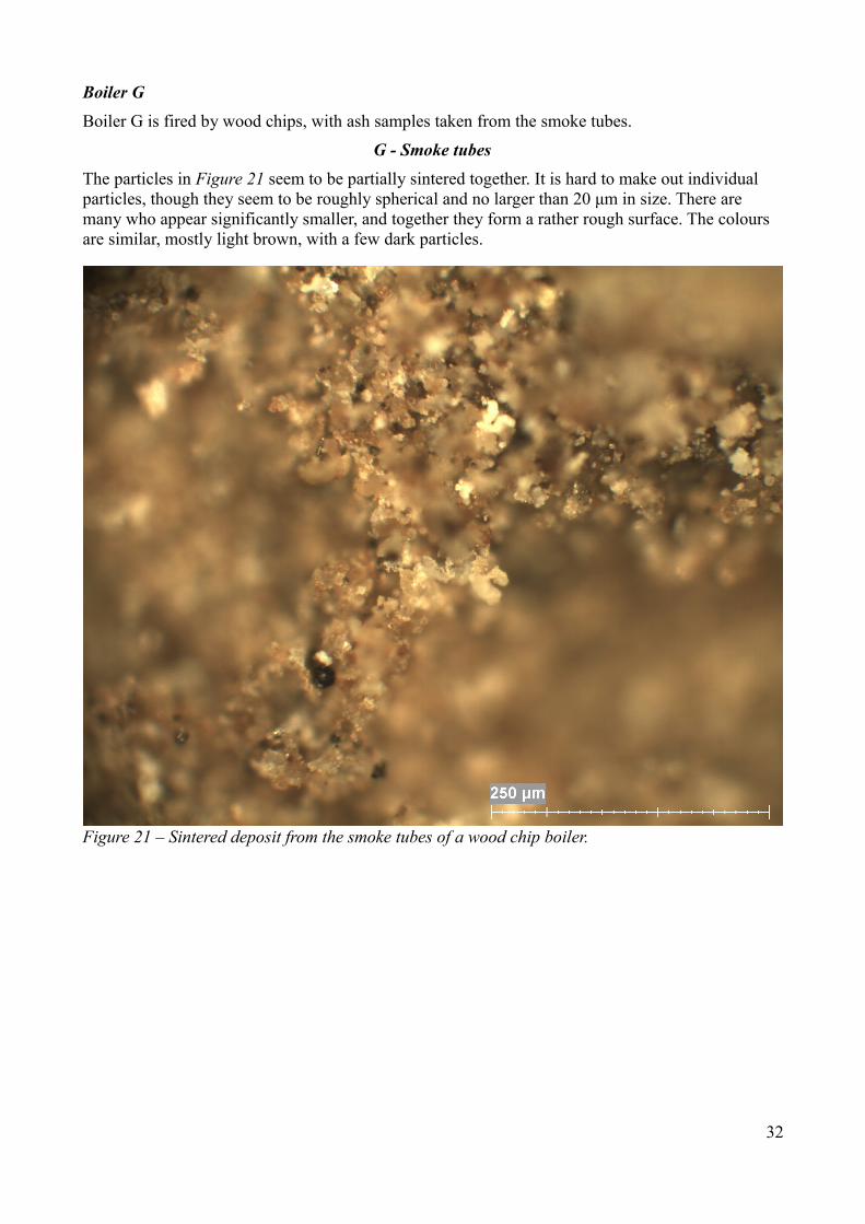
Boiler G is fired by wood chips, with ash samples taken from the smoke tubes.
G - Smoke tubes
The particles in Figure 21 seem to be partially sintered together. It is hard to make out individual particles, though they seem to be roughly spherical and no larger than 20 μm in size. There are many who appear significantly smaller, and together they form a rather rough surface. The colours are similar, mostly light brown, with a few dark particles.
Figure 21 – Sintered deposit from the smoke tubes of a wood chip boiler.
32
5.3. Laser Sieving
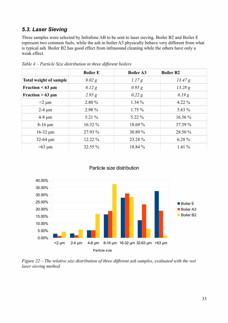
Three samples were selected by Infrafone AB to be sent to laser sieving. Boiler B2 and Boiler E represent two common fuels, while the ash in boiler A3 physically behave very different from what is typical ash. Boiler B2 has good effect from infrasound cleaning while the others have only a weak effect.
Table 4 – Particle Size distribution in three different boilers
Boiler E Boiler A3 Boiler B2
Total weight of sample 9.02 g 1.17 g 13.47 g
Fraction < 63 μm 6.12 g 0.95 g 13.28 g
Fraction > 63 μm 2.95 g 0.22 g 0.19 g
<2 μm 2.80 % 1.34 % 4.22 %
2-4 μm 2.98 % 1.75 % 5.63 %
4-8 μm 5.21 % 5.22 % 16.56 %
8-16 μm 16.32 % 18.69 % 37.39 %
16-32 μm 27.93 % 30.89 % 28.50 %
32-64 μm 12.22 % 23.28 % 6.28 %
>63 μm 32.55 % 18.84 % 1.41 %
Figure 22 – The relative size distribution of three different ash samples, evaluated with the wet laser sieving method
33
<2 μm 2-4 μm 4-8 μm 8-16 μm 16-32 μm 32-63 μm >63 μm0.00%
5.00%
10.00%
15.00%
20.00%
25.00%
30.00%
35.00%
40.00%
Particle size distribution
Boiler E
Boiler A3
Boiler B2
Particle size
5.4. Density
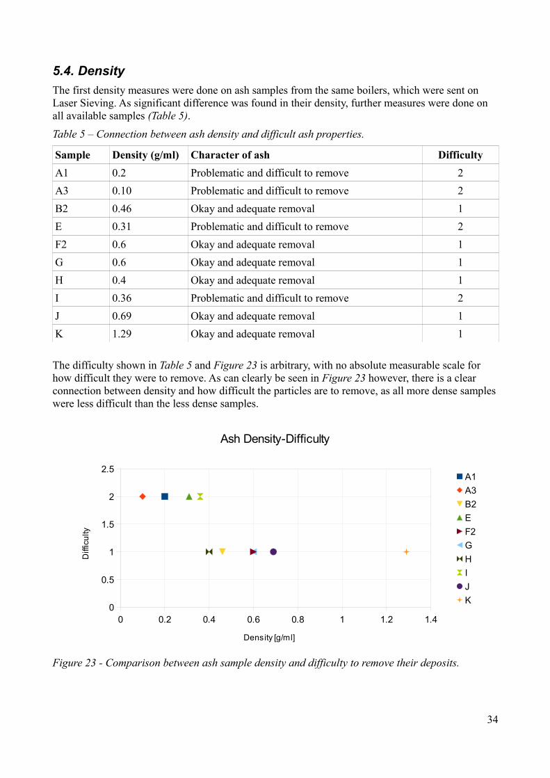
The first density measures were done on ash samples from the same boilers, which were sent on Laser Sieving. As significant difference was found in their density, further measures were done on all available samples (Table 5).
Table 5 – Connection between ash density and difficult ash properties.
Sample Density (g/ml) Character of ash Difficulty
A1 0.2 Problematic and difficult to remove 2
A3 0.10 Problematic and difficult to remove 2
B2 0.46 Okay and adequate removal 1
E 0.31 Problematic and difficult to remove 2
F2 0.6 Okay and adequate removal 1
G 0.6 Okay and adequate removal 1
H 0.4 Okay and adequate removal 1
I 0.36 Problematic and difficult to remove 2
J 0.69 Okay and adequate removal 1
K 1.29 Okay and adequate removal 1
The difficulty shown in Table 5 and Figure 23 is arbitrary, with no absolute measurable scale for how difficult they were to remove. As can clearly be seen in Figure 23 however, there is a clear connection between density and how difficult the particles are to remove, as all more dense sampleswere less difficult than the less dense samples.
Figure 23 - Comparison between ash sample density and difficulty to remove their deposits.
34
0 0.2 0.4 0.6 0.8 1 1.2 1.40
0.5
1
1.5
2
2.5
Ash Density-Difficulty
A1
A3
B2
E
F2
G
H
I
J
K
Density [g/ml]
Diff
icu
lty
6. Discussion
6.1. Microscopy
The results from the optical microscopy study show that there are no substantial and easy to observedifference in the particle sizes of the studied samples. For both partially sintered samples (Table 2) and complete powder samples (Table 3), most of the samples appear similar in particle sizes. While the images gained from the optical microscope did not give as much information as desired, they gave a rough estimate of particle sizes.
While most of the samples appeared fairly homogeneous, the sample from Boiler C was very inhomogeneous. The sample was also very sand-like in appearance, with coarse and rough grains, as opposed to a smooth powder for the other samples. The major reason for this sand-like appearance is likely the means with which it was collected and the type of boiler used. Boiler C is a so-called Bubbling Fluidized Bed (BFB), which mean that the fuel is supported in a fluidizing stream of air along with the bed material. The bed material is often quartz sand, and the smaller particles of this can leave the bed with the flue gas and fly ash. (Livingston). If the sample instead had been taken from deposits found inside the boiler rather than from a soot pocket where material from the flue gas have rained down, the appearance would likely be closer to that of the other samples. Another sample, which behaved very different from the others, was sample A3. This sample is extremely light and even the slightest shift of air in the cleanroom caused the loose chunks to shift in the petri dish. Along with this, it was also acting very sticky, parts of the chunks sticking to the spatula when it was moved around. Inside the plastic resalable bag it is kept, a thin layer of fine powder has also formed on the inside. The reason for this sample acting so sticky has not been determined. There could be a stronger binding force acting between the particles, but there is also no indication as to what this could be. If there had been an electrostatic charge, it would likely have been observed in some of the particles behaviours to different objects. As they seem to act the same to everything, it is likely not an electrostatic force. An alternative could be that the particles are extremely light, and as such have an easier time defying gravity and stick to other objects.
As no major differences could be noticed with the optical microscopy in the physical appearance of different samples, on neither particle size nor particle shape, other methods of evaluation needed to be considered. From the optical microscope images, the particle sizes could be approximated to be 50 μm or less. The Swedish Cement and Concrete Research Institute (CBI) were contacted and, Alexander Eriksson-Brandels gave guidance on the usability of the method in this case. Regular sieving methods use a mesh with square or round holes. They are stacked from a course to a finer mesh that the dry powder is shaken through. This gradually finer mesh gives different size fractions.The fractions for the smallest particles are in the range of 0-63 μm, and the procedure requires a large sample (600 g). Along with this, it is problematic to handle samples with a large amount of powder less than 500 μm in size, which could clog the finer mesh and cause a lot of dusting. All thisconsidered with the information that was already acquired about the samples and the particle sizes, the method ”laser-sieving” was suggested as a possible alternative, which are able to handle smallerfractions, though at an increased cost.
Particle sizes in boilers are reported to be less than a micron to a few hundred microns in size, which was not what was observed with the optical microscope (Van Beek et al.). Moreover, roughly50% of the ash should be in the 150-250 μm range (Sveriges tekniska forskningsinstitut). This is notat all, what was observed with the optical microscope, where only one sample (C) even contained
35
particles close to this size. It could be that the majority of the particles sticking are of the smaller fraction. According to Van Beek et al. (2001), such could be the case. Another possibility is that most measurements of particle sizes in fly ash have been made with regular sieving methods. This is not a good way to measure particle sizes when a large fraction of fine powder is present according to Alexander Eriksson-Brandels at CBI. The fine powder can clog the mesh and artificially cause it to appear to have larger particle sizes. This is especially true if the powder have a tendency to agglomerate and stick to each other, which have been frequently observed for these powders. From another study using ash (Nordström et al.) it was confirmed that regular sieving can make samples appear courser then they are found to be with laser sieving. All these factors considered, a few selected samples were sent for evaluation using a laser sieving analysis method.
6.2. Particle size
There is often a connection drawn between particle size and fouling. Particle sizes in a refuse waste incinerator are often in the range of a few to a few hundred micrometres, while the observed deposits rarely have particles larger than 30 μm (Van Beek et al.). Some of this is contributed to thermophoresis (Abd-Elhady and Malayeri), which is found to affect smaller particles more than larger particles. Thermophoresis is viewed as the dominant deposition mechanic for particles up to afew microns, while larger particle deposition mechanics are dominated by impaction (Van Beek et al.). The particle sizes observed with the optical microscopy for the powder samples from the deposits, along with the laser sieving analysis, seem consistent to what Van Beek et. al. (2001) found in their study, where smaller particles stick more than larger. The particle sizes are larger thanthose commonly seen as mostly affected by thermophoresis.,The exact mechanics behind their deposition and why the smaller particles are more affected is still not determined.
Diffusion is frequently mentioned alongside thermophoresis (Van Beek et al.), and since the forces act in the same direction (Marner), it may be hard to tell apart from Thermophoresis in any practicalapplication in boilers.
A possible secondary interaction that can take place is electrophoresis or electrostatic charging. According to Eklund and Rodin (2004), one of the mechanisms with which particles can be transported from the flue gas is electrophoresis. It is also mentioned that one of the boilers has a large amount of electrically charged particles, which cause problem with thick deposits. When the flue gas flow through the chimney the particles can collide with walls and objects and gain an electrical charge. This can then make them attract to different charged objects, possibly resulting in fouling. While electrostatic fouling is clearly mentioned in some articles (Eklund and Rodin), (Harnevie et al.), it is seldom more than mentioning its occurrence. The same can be said about electrophoresis, with the information available for electrostatic charging and electrophoresis is either very limited or brief, or doesn't touch on the practical implications behind the mechanics (Keh and Chang), (Matsusyama and Yamamoto), (Zhang et al.). The effect does not seem properly evaluated for gas-side fouling in a boiler setting and would need further analysis.
36
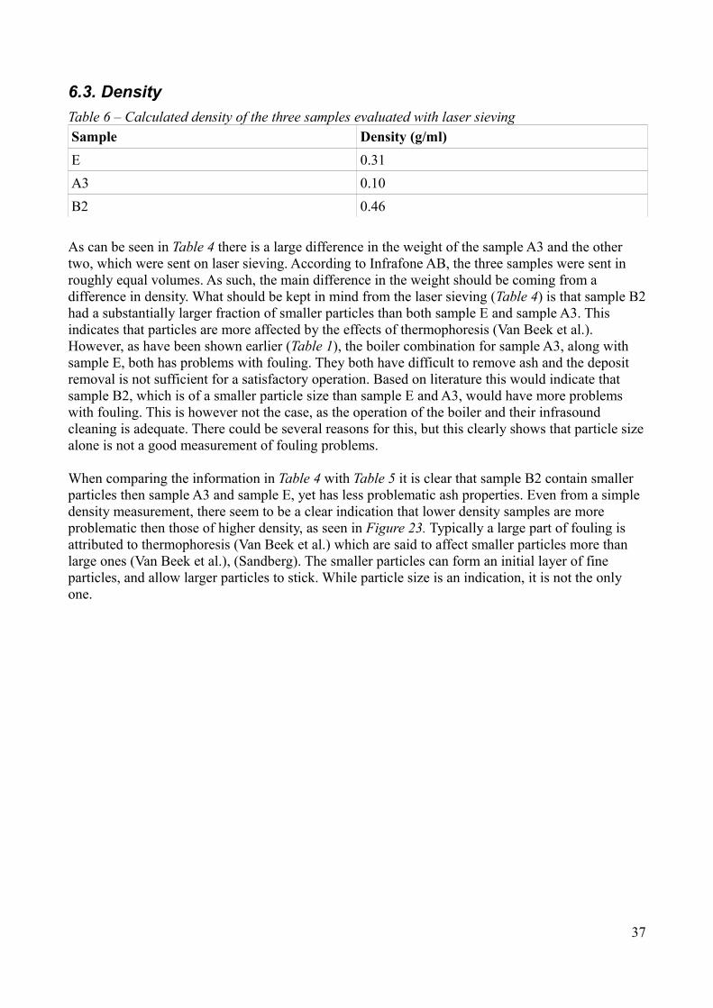
6.3. Density
Table 6 – Calculated density of the three samples evaluated with laser sievingSample Density (g/ml)
E 0.31
A3 0.10
B2 0.46
As can be seen in Table 4 there is a large difference in the weight of the sample A3 and the other two, which were sent on laser sieving. According to Infrafone AB, the three samples were sent in roughly equal volumes. As such, the main difference in the weight should be coming from a difference in density. What should be kept in mind from the laser sieving (Table 4) is that sample B2had a substantially larger fraction of smaller particles than both sample E and sample A3. This indicates that particles are more affected by the effects of thermophoresis (Van Beek et al.). However, as have been shown earlier (Table 1), the boiler combination for sample A3, along with sample E, both has problems with fouling. They both have difficult to remove ash and the deposit removal is not sufficient for a satisfactory operation. Based on literature this would indicate that sample B2, which is of a smaller particle size than sample E and A3, would have more problems with fouling. This is however not the case, as the operation of the boiler and their infrasound cleaning is adequate. There could be several reasons for this, but this clearly shows that particle sizealone is not a good measurement of fouling problems.
When comparing the information in Table 4 with Table 5 it is clear that sample B2 contain smaller particles then sample A3 and sample E, yet has less problematic ash properties. Even from a simple density measurement, there seem to be a clear indication that lower density samples are more problematic then those of higher density, as seen in Figure 23. Typically a large part of fouling is attributed to thermophoresis (Van Beek et al.) which are said to affect smaller particles more than large ones (Van Beek et al.), (Sandberg). The smaller particles can form an initial layer of fine particles, and allow larger particles to stick. While particle size is an indication, it is not the only one.
37
6.3.1. Why density?
Thermophoresis is an inertia based effect, and for a powder of the same material but with varying sizes, the smaller particles will be affected more than the larger ones. When you are not just interested in what particles are affected in a given sample, however, it could be more interesting to look deeper on the actual mechanics behind thermophoresis. There are several physical properties that play a role in the inertia of a particle; size, shape, porosity, and material. When you only changethe size of the particle, it will also become lighter. A flat flake will however also be lighter than a sphere, while appearing to have the same size in regular sieving methods. Similarly, a more porous particle of the same shape and size will also be lighter than a solid particle. Lastly, a particle consisting of a lighter material will also be lighter. When a particle is subject to the same external force, but have less mass, it will move more than a particle with higher mass, which is the mechanism behind which thermophoresis is said to work; smaller particles are more mobile and move more than larger ones over the temperature gradient (Abd-Elhardy and Malayeri).
While moving particles would be one important component of fouling, it is not the only one. First, the particle need to move sufficiently close to a surface, then it also need to stick to it. Binding forces are typically based on the surface area of a particle. Both the cross-section and surface area of a spherical particle have a linear relationship to the radius squared, while the volume, and as suchmass, of the particle is related to the cubic of the radius. The implication of this is that the surface area to mass ratio will increase the smaller the particle is.
Since there seem to be a relationship between the density of the powder and the formation of problematic ash deposit, one must consider what the cause of this could be. We have already established that the binding strength is related to the surface area. If this were the only thing to consider, then larger particles would foul more, due to an absolute larger surface area, and as such, greater binding forces. We have established that smaller particles will contact more to the surface, but there are also other mechanisms that can remove the particles after making contact. The most notable mechanisms are gravity and collision with moving particles (Abd-Elhady and Malayeri). Gravity can and will certainly play a role with removal of deposits. Each individual particle does not seem largely affected by this. It is typically not before a large deposit have been formed that the gravity take over, breaking it loose from the surface it formed upon, and fall down in a big chunk (Sandberg). If gravity had played a big role in formation of deposits, it would come in effect much earlier. Combining this with the fact that the flow of flue gas is often vertical in the colder sections where the particles are solid, most of the fouling would be on the upward side of tubes. Significant fouling is usually seen on the windward side of the tubes (Sandberg). With those things considered, it leaves us impaction and shear as the primary components of natural deposit removal and growth inhibition. Particles in the flue gas will make contact with the deposits, and if with sufficient energy,remove some of the deposit. It would seem a natural conclusion of this, that smaller and lighter particles would be easier to remove, but this is exactly opposite to what have been observed here. If a smaller or lighter particle is subject to the same kinetic energy, it would require a larger binding force to prevent itself from being displaced. Then why is this not happening? The answer could be trivial, but it may not be intuitive.
The flue gas typically moves at a fixed speed, and the particles are suspended in the stream. They will largely move at the same speed as the flue gas, and will have a kinetic energy related to the velocity and their individual mass. When a particle then collides with a deposit, it will exert a force on it, and if great enough, remove some of the deposit. One possible explanation to the lower density powders showing greater fouling is that the particles that make up the deposits are the same kind that also are found in the flue gas itself. While a lighter particle are more affected by the same
38
kinetic energy (it would need to move more to preserve the energy), if the density of the particles in the deposit is half that of another deposit, then the particles in the flue gas itself would also be half the density. This in turn would mean that their kinetic energy was reduced in half. All this while the binding strength of the deposit particles stay the same, as it is related to the surface area, which was unchanged. With only half the kinetic energy available to break the bounds of the deposit, it would grow larger than for a more dense powder, and be more problematic. Since acoustic soot blowing operates by creating resonance in the flue gas, it will create fluctuations in the gas flowing past the deposits. This gas flow will contain the same kind of particles as can be found in the particles. While there is a normal gas flow through the chimney, the added energy and resonance from the infrasound cleaning alter the flow characteristics of the gas. The low speed regions shown in Figure4 will shrink and allow higher speed gas, and particles, to flow closer to the deposits. It could be that the inertia of the more dense particles will not be able to follow the streamlines of the flue gas, and as such to a greater degree collide with the deposits when the infrasound cleaning is in operation. This will put increased stress and shear on the deposits, potentially limiting them from growing larger. The resonance will also cause vibrations within the deposits, and it could be that thereduced binding strength to mass ratio of dense particles are more affected by these vibrations. As no other clear connection could be drawn between which particles were sufficiently removed, and those who were not, it stand to reason that the density play a major role in deposit growth and removal through acoustic means, as size and appearance did not.
7. ConclusionsA connection between particle size and difficult deposits cannot be made. There is a clear connection between the density of an ash sample and difficulty to remove the corresponding deposits. Samples with a high density have shown better results in terms of infrasound efficiency without exceptions than those with a low density.
8. ContinuationTo increase the understanding of what connection density have to fouling, it would be of interest to evaluate a larger range of particle samples. Those should ideally include flue gas samples both before and after affected areas, to evaluate if the gas composition changes. These should be compared to samples taken from the deposits. A scientific method for density measurements should be developed. This should include how to handle sintered deposits, along with getting consistent density measurements from identical samples. The method must be able to handle samples that havebeen shaken more compact, but still be simple to use. It could be beneficial to create an experimental setup where different density samples could be tested and deposit growth measured.
39
9. ACKNOWLEDGEMENT
I would first like to thank my thesis supervisor Martin Ellebro at Infrafone AB for his friendly and supportive attitude. He was always there to give advice or answer questions whenever I needed it. He also helped me with the practical things I couldn't easily do myself.
I would also like to thank professor Urban Wiklund of the Department of Engineering Sciences at Uppsala University. He provided valuable input and allowed me to see what the thesis needed.
I would also like to acknowledge senior lecturer Åsa Kassman of the Department of Engineering Sciences at Uppsala University. She was there to help me when I didn't know who else to turn to, even though it wasn't her responsibility.
Finally, I am forever grateful to my parents and to my partner for your encouragement and support throughout my years of study and through the process of researching and writing this thesis. I could not have done this without them. Thank you.
Author
Arvid Bo Cedervall
40
10. Reference List
Abd-Elhady, M.S. & Malayeri, M.R. (2013) 'Asymptotic characteristics of particulate deposit formation in exhaust gas recirculation (EGR) coolers', Applied Thermal Engineering, 60(1-2), pp. 96-104.
Bach, G., Zimmmann, G., Kopinke, F.-D., Barendregt, S., Van Den Oosterkamp, P. & Woerde, H. (1995) 'Transfer-line heat exchanger fouling during pyrolysis of hydrocarbons. 1. Deposits from dry cracked gases', Industrial and Engineering Chemistry Research, 34(4), pp. 1132-1139.
Bouris, D., Konstantinidis, E., Balabani, S., Castiglia, D. & Bergeles, G. (2005) 'Design of a nove, intensified heat exchanger for reduced fouling rates', International Journal of Heat and Mass Transfer, 48(18), pp 3817-3832.
Calisto, H., Martins, N. & Afgan, N. (2008) 'Diagnostic system for boilers and furnaces using CFD and neural networks', Expert Systems with Applications, 35(4), pp 1780-1787.
Davidsson, K., Johansson, I., Stålenheim, A. & Boman, K. (2014) Sotningsmetoder för panor som använder besvärliga bränslen, Available at: http://www.varmeforsk.se/rapporter/ #1257 (Accessed 18 August 2015).
Eklund, A. & Rodin, Å. (2004) Sotningsmetodernas effektivitet och konsekvenser på förbränningsanläggningar för olika typer av bränslen, Available at: http://www.varmeforsk.se/rapporter/ #878 (Accessed 27 May 2015).
Enestam, S., Boman, C., Niemi, J., Boström, D., Backman, R., Mäkelä, K. & Hupa, M. (2011) 'Occurrence of Zinc and Lead in Aerosols and Deposits in the Fluidized-Bed Combustion of Recovered Waste Wood. Part 1: Samples from Boilers', Energy and Fuels, 25(4), pp 1396-1404.
Harnevie, H., Hägerstedt, L.-E. & Nyquist, G. (2002) Kontinuerlig mätning av stoft i rökgaser, Available at: http://www.varmeforsk.se/rapporter/ #772 (Accessed 26 May 2015).
Iribarne, J.V., Anthony, E.J. & Iribarne, A. (2003) 'A scanning electron microscope study on agglomeration in petroleum coke-fired FBC boilers', Fuel Processing Technology, 82(1), pp 27-50.
Konstandopoulus, A.G. (2000) 'Deposit growth dynamics: particle sticking and scattering phenomena', Powder Technology, 109(1-3), pp 262-277.
Keh, H.J. & Chen, S.B. (1993) 'Diffusiophoresis and Electrophoresis of Colloidal Cylinders', Langmuir, 9(4), pp 1142-1149.
Livingston, W.R. (2007) Biomass ash characterisitcs and behaviour in combustion, gasification
41
and pyrolysis systems, Available at: https://antioligarch.files.wordpress.com/2014/12/biomass-fly-ash-characteristics-behaviour-in-combustion.pdf (Accessed 2 June 2015).
Mann, I., Boman, K., Stålheim, A. & Nylén, L. (2014) Slagging and fouling – Idbäcken P3 soot blowing evaluation and heat transfer model description, Available at: http://www.varmeforsk.se/rapporter/ #1257 Bilaga C (Accessed 18 August 2015).
Marner, W.J. (1996) 'Progress in gas-side fouling of heat-transfer surfaces: 1989-1995', Applied Mechanics Reviews, 49(10 part 2), pp S161-S166.
Matsusyama, T. & Yamamoto, H. (2006) 'Impact charging of particulate materials', Chemical Engineering Science, 61(7), pp 2230-2238.
Nordstrom, E., Holmström, M. & Sandström, T. (2004) Användning av askor från förbränning med returpappersslam inom gruvindustrin, Available at: http://www.energiaskor.se/pdf-dokument/Rapport%20862.pdf (Accessed 16 October 2015).
Reichelt, J., Pfrang-Stotz, G., Bergfeldt, B., Seifert, H. & Knapp, P. (2013) 'Formation of deposits on the surfaces of superheaters and economisers of MSW incinerator plants', Waste Management, 33(1), pp 43-51.
Sandberg, J. (2007) Fouling in biomass fired boilers. Licentiate thesis, Mälardalen University.
Skaardal, R. (1984) Utvärdering av sotningsmetoder, Available at: http://www.varmeforsk.se/rapporter/ #176 (Accessed 27 May 2015).
Strömberg, B. & Svärd, S.H. (2012) Bränslehandboken 2012, Available at: http://www.varmeforsk.se/rapporter/ #1234 (Accessed 17 May 2015).
Svedin, K., Wallin, E. & Ahlroth, M. (2008) Sotningsmetoder och sotångsförbrukning i svenska sodapannor, Available at: http://www.varmeforsk.se/rapporter/ #1086 (Accessed 27 May 2015).
Van Beek, M.C., Rindt, C.C.M., Wijers, J.G. & Van Steenhoven, A.A. (2001) 'Analysis of fouling inrefuse waste incinerators', Heat Transfer Engineering, 22(1), pp 22-31.
Zhang, L., Bi, X. & Grace, J.R. (2015) 'Measurements of electrostatic charging of powder mixtures in a free-fall test device', Procedia Engineering, 102, pp 295-304.
42