Embed Size (px)
Citation preview
Composite Structures 174 (2017) 176–186
Contents lists available at ScienceDirect
Composite Structures
journal homepage: www.elsevier .com/locate /compstruct
Evaluation of effective material properties in magneto-electro-elasticcomposite materials
http://dx.doi.org/10.1016/j.compstruct.2017.03.1040263-8223/� 2017 Elsevier Ltd. All rights reserved.
⇑ Corresponding author.E-mail address: [email protected] (J. Sladek).
Jan Sladek a,⇑, Vladimir Sladek a, Miroslav Repka a, Jozef Kasala b, Peter Bishay c
a Institute of Construction and Architecture, Slovak Academy of Sciences, 84503 Bratislava, Slovakiab Faculty of Special Technology, University of Trencin, 91150 Trencin, SlovakiacCollege of Engineering and Computer Science, California State University, Northridge, CA, United States
a r t i c l e i n f o a b s t r a c t
Article history:Received 24 March 2017Revised 28 March 2017Accepted 29 March 2017Available online 12 April 2017
Keywords:Meshless local integral equationGradient theorySize effectMagnetoelectroelastic solidEffective material parameters
The meshless local integral equation method is developed to analyze general two-dimensional boundaryvalue problems in size-dependent magnetoelectroelastic solids. A consistent theory is developed for sizedependent magnetoelectroelasticity. The strain gradients are considered in the constitutive equations forelectric displacement and magnetic induction. The governing equations are derived with the correspond-ing boundary conditions using the variational principle. The local integral equations are subsequentlyderived and the meshless moving least square (MLS) numerical method is implemented to solve theseequations.
� 2017 Elsevier Ltd. All rights reserved.
1. Introduction
Modern smart structures made of piezoelectric and piezomag-netic materials offer certain potential performance advantagesover conventional ones due to their capability of convertingenergy from one type to another, among magnetic, electric, andmechanical [1,2]. It is well known that some composite materialscan provide superior properties compared to their virginmonolithic constituent materials [3]. The irregularity in the spatialarrangement of the fibers and their geometry can influence theestimation of the effective material properties of the unidirectionalcomposite. The experimental approaches are not convenientfor an optimal design of composites due to the expensive costof the measurements and the low efficiency. Therefore,mathematical and numerical models are frequently utilized toget homogenized material properties directly from those of theconstituents and from their microstructure. Then, these materialproperties are used for numerical analyses at macroscopic scale.However, sometimes such analyses are not accurate enough,especially if the size of the structure is comparable to the materiallength scale.
Due to their superior physical, electrical, optical, chemical andother properties, the nano/micro structures were expanded intomany areas such as nano-electromechanical devices [4], spaceand bio-engineering [5], actuators [6], and nanocomposites [7,8].The validity of using the classical continuum mechanics for micro/nano structures is inconclusive. Experimental as well as discreteatomistic methods such as molecular dynamics (MD) simulations[9,10] have been utilized in understanding and analysing the beha-viour of nano/micro structures. However, these methods are highlyexpensive and not applicable to real sized structures due to theextremely high computer hardware requirements. Fortunately,the continuum theory can be applied for these structures afterproper improvements or enhancements [11]. Recent experimentshave demonstrated that when the dimensions of the structureare of the same order of the material length scale, the stiffness ofthe structure increases. Size-dependent behaviour has beenobserved in many studies [12–15]. This phenomenon can beexplained by the presence of significant strain gradients whichappear because of the small size of the microstructural elements.Thus, the behaviour of the mesoscopic structural elements couldbe described by the continuum theory enriched by incorporationof strain gradients. Then, a consistent size-dependent continuummechanics theory can be a more efficient alternative to the atomis-tic models.
Magnetoelectroelastic (MEE) composites are made of piezoelec-tric and magnetostrictive phases coupled by a strain field. From
J. Sladek et al. / Composite Structures 174 (2017) 176–186 177
earlier investigation for macro-sized layered MEE, it is well-knownthat effective composite coefficients are higher than their con-stituents [16]. A similar enhancement of effective coefficients hasbeen observed for fiber composites. Kuo and Wang [17] optimizedthe effective magnetoelectric (ME) voltage coefficient of fibrouscomposites made of piezoelectric and piezomagnetic phases.They showed that at an optimal orientation of fibers, the effectivein-plane and out-of-plane ME coefficient can be enhancedmany-fold. Wang and Pan [18] investigated the influence of imper-fect matrix-fiber bond on the ME coefficient under longitudinalshear.
The influence of strain gradients in the gradient theory on theeffective material properties of MEE composites, if coated piezo-electric fiber is embedded into the piezomagnetic matrix, is inves-tigated in the present paper. This problem was analyzed beforeusing the classical elasticity theory. Kuo [19] and Kuo and Pan[20] analyzed fibrous composites with piezoelectric and piezomag-netic phases only under anti-plane shear deformation, whereasSladek et al. [21] analyzed the same composites under in-planedeformation. Ebrahimi and Dabbagh [22] also studied the flexuralwave propagation responses of smart FG MEE nanoplates via non-local strain gradient theory. If the thickness of the coating layer isvery small, the strain gradients should be included into the magne-toelectroelasticity mathematical model. The governing equationsfor magnetoelectroelastic solids in gradient elasticity with the cor-responding boundary conditions are derived from the variationalprinciple in the present paper.
Meshless methods are becoming very popular in numericalanalyses of engineering problems. A variety of meshless methodshas been proposed so far. They can be derived either from aweak- or strong-form. The weak formulation can be performedon the global domain or a set of local subdomains. Backgroundcells are required in the global weak formulation to performnumerical integration. However, no background cells are requiredin the local weak formulation. The moving least squares (MLS)approximation is often used for approximating the trial functions.It yields C1 continuity counterpart to conventional discretizationmethods, where discontinuity of secondary fields at the interfacesof elements occurs. Meshless methods have been also applied topiezoelectric problems [23,24]. Many meshless formulations canbe defined on the base of the meshless local Petrov-Galerkin(MLPG) method, since trial and test functions can be chosen fromdifferent functional spaces [25–27]. The test functions in the MLPGmethod can be arbitrary. The formulation with a Heaviside stepfunction as the test functions [28,29] leads to a simple form andit has been applied successfully to various boundary value prob-lems [30–34].
In the present paper, the MLPG method, with the gradient the-ory, is applied to 2-D problems of magnetoelectroelasticity. Thecorresponding governing equations are satisfied in a weak formon small fictitious subdomains. Nodal points are randomly dis-tributed over the analyzed domain. Each node is surrounded bya small circle for simplicity, but without loss of shape generality.Numerical integration over circles can be easily carried out. Thelocal integral equations have a very simple nonsingular form.The MLS scheme is used for spatial approximations of the displace-ments, the electric and magnetic potentials [35]. Performing thespatial integrations, a system of linear algebraic equations forthe unknown nodal values is obtained. The proposed computa-tional method is applied to evaluation of effective material proper-ties of a piezomagnetic matrix with regularly distributedpiezoelectric fibers with a nano-sized coating layer. The influenceof the coating layer on the effective MEE coefficients isinvestigated.
2. Basic equations for electric- and magnetic-strain gradienttheory
The electric field-strain gradient theory for nano-dielectricsintroduced by Hu and Shen [36] is extended here for a nano-magnetoelectroelastic material. The strain gradients exist only inthe higher order stress, electric displacement and magnetic induc-tion fields. Then, the constitutive equations are given by
rij ¼ cijklckl � ekijEk � qkijHk;
sjkl ¼ �f ijklEi � hijklHi þ gjklmnigmni;
Dk ¼ ekijcij þ eklEl þ aklHl þ f klmnglmn;
Bk ¼ qkijcij þ aklEl þ lklHl þ hklmnglmn; ;
ð1Þ
where cijkl; ekij; qkij; ekl;akl;lkl and f ijkl; hijkl; gjklmni are the materialproperty tensors. Particularly, ekl;lkl; cijkl are the second-order per-mittivity, permeability and the fourth-order elasticity constant ten-sors, respectively. Symbol ekij denotes the piezoelectric coefficient,qkij is the piezomagnetic coefficient, akl is the electromagnetic coef-ficient. The electric field–strain gradient coupling coefficient tensorf ijkl represents the higher-order electromechanical coupling inducedby the strain gradient, and hijkl is the magnetic field–strain gradientcoupling coefficient tensor. The higher-order elastic parametersgjklmni represent the purely the strain gradient elasticity theory.Symbols sijk and Di denote the higher-order stress tensor and elec-tric displacement vector, respectively. A subscript preceded by acomma denotes differentiation with respect to the correspondingCartesian coordinate. The Eistein summation is employed forrepeated lowercase indices.
The strain tensor cij, the electric field vector Ej and the magneticfield vector Hl are related to the displacements ui, the electricpotential / and the magnetic potential w, respectively by
cij ¼12ðui;j þ uj;iÞ; Ej ¼ �/;j; Hj ¼ �w;j ð2Þ
The strain gradient tensor [37] is defined as
gijk ¼ cij;k ¼12ðui;jk þ uj;ikÞ ð3Þ
with exhibiting the symmetry cij ¼ cji, gijk ¼ gjik. The constitutiveequations (1) for orthotropicmaterial can bewritten in amatrix form:
r11
r33
r13
26664
37775 ¼
c11 c13 0
c13 c33 0
0 0 c44
26664
37775
c11
c33
2c13
26664
37775�
0 e31
0 e33
e15 0
26664
37775
E1
E3
" #
�0 q31
0 q33
q15 0
26664
37775
H1
H3
" #
or r ¼ Cc� LE�MH ð4Þ
D1
D3
� �¼ 0 0 e15
e31 e33 0
� � c11c332c13
24
35þ e11 0
0 e33
� �E1
E3
� �þ a11 0
0 a33
� �H1
H3
� �
þm2 0 0 e15 0 0 e15e31 e31 0 e33 e33 0
� �g111
g331
2g131
g113
g333
2g133
266666664
377777775
or D¼ LTcþ JEþAHþm2Fg; ð5Þ
178 J. Sladek et al. / Composite Structures 174 (2017) 176–186
B1
B3
� �¼ 0 0 q15
q31 q33 0
� � c11c332c13
264
375þ a11 0
0 a33
� �E1
E3
� �þ l11 0
0 l33
� �
� H1
H3
� �þm2 0 0 q15 0 0 q15
q31 q31 0 q33 q33 0
� �g111
g331
2g131
g113
g333
2g133
2666666664
3777777775
or B ¼ MTcþ AEþ IHþm2Og; ð6Þ
s111s331s131s113s333s133
2666666664
3777777775¼ �m2
0 e310 e33e15 00 e310 e33e15 0
2666666664
3777777775
E1
E3
� ��m2
0 q31
0 q33
q15 00 q31
0 q33
q15 0
2666666664
3777777775
H1
H3
� �
þ l2
c11 c13 0 0 0 0c13 c33 0 0 0 00 0 c44 0 0 00 0 0 c11 c13 00 0 0 c13 c33 00 0 0 0 0 c44
2666666664
3777777775
g111
g331
2g131
g113
g333
2g133
2666666664
3777777775
or s ¼ �m2FTE�m2OTHþ l2Ggð7Þ
where gradient theory parameters gjklmni are proportional to elasticparameters cklmn by the internal length material parameter l [38].Similarly, the electric field-strain gradient and magnetic field-strain gradient coupling coefficient f ijkl and hijkl are expressed bypiezoelectric and piezomagnetic coefficients, respectively, and ascaling parameter m.
Consider a piezoelectric solid in domain Vwith boundary C. Thevariation of the electric Gibbs free energy in gradient theory ofmagnetoelectroelastic solids is given by
dU ¼ZVðrijdeij þ sijkdgijk þ Dkd/;k þ Hkdw;kÞdV : ð8Þ
Applying the Gauss divergence theorem, one gets
dU ¼ZVðrijdui;j þ sijkdui;jk þ Dkd/;k þ Hkdw;kÞdV
¼ �ZVðrij;jdui þ sijk;kdui;j þ Dk;kd/þ Hk;kdwÞdV
þZCðnjrijdui þ nksijkdui;j þ nkDkd/þ nkHkdwÞdC
¼ �ZV½ðrij;j � sijk;jkÞdui þ Dk;kd/þ Hk;kdw�dV
þZC½njðrij � sijk;kÞdui þ nksijkdui;j þ nkDkd/þ nkHkdw�dC
¼ �ZV½ðrij;j � sijk;jkÞdui þ Dk;kd/þ Hk;kdw�dV
þZC½tidui þ Ridsi þ Qd/þ Sdw�dC; ð9Þ
where the traction vector is defined as
ti ¼ njðrij � sijk;kÞ � @qi
@pþXc
kqiðxcÞkdðx� xcÞ ð10Þ
with qi :¼ nkpjsijk ð11Þand kqiðxcÞk :¼ qiðxc þ 0Þ � qiðxc � 0Þ is the jump at a corner on theoriented boundary contour C. Symbol pi is the Cartesian component
of the unit tangent vector on C, si :¼ @ui@n , Ri :¼ nknjsijk, Q :¼ nkDk,
S :¼ nkHk.In derivation of dU, the following identity is invoked:
nksijkdui;j ¼ qi@dui
@pþ Rid
@ui
@n
� �ð12Þ
The primary fields ðui; si; /; wÞ are energetically conjugatedwith ðti; Ri; Q ; SÞ. The work of the external generalized forcesð�ti; �Ri; �Q ; �SÞ is given by
dW ¼ZCt
�tiduidCþZCR
�RidsidCþZCQ
�Qd/dCþZCS
�SdwdC ð13Þ
From the principle of virtual work dU � dW ¼ 0, the followinggoverning equations are obtained from Eqs. (9) and (13),
rij;jðxÞ � sijk;jkðxÞ ¼ 0; Dk;kðxÞ ¼ 0; Hk;kðxÞ ¼ 0; ð14Þand two kinds of boundary conditions (b.c.) are:
Essential b:c: :
uiðxÞ ¼ �uiðxÞ onCu; Cu � C
siðxÞ ¼ �siðxÞ onCs; Cs � C
/ðxÞ ¼ �/ðxÞ onC/; C/ � C
wðxÞ ¼ �wðxÞ onCw; Cw � C
ð15Þ
Natural b:c: : tiðxÞ ¼ �tiðxÞ onCt ; Ct [ Cu ¼ C; Ct \ Cu ¼ £
RiðxÞ ¼ �RiðxÞ onCR; CR [ Cs ¼ C; CR [ Cs ¼ £
QðxÞ ¼ �QðxÞ onCQ ; CQ [ C/ ¼ C; CQ [ C/ ¼ £
SðxÞ ¼ �SðxÞ onCS; CS [ Cw ¼ C; CS [ Cw ¼ £
ð16Þ
3. The meshless local integral equation method
The MLPG method is the local weak-form with local fictitioussubdomains Xs. It is a small region constructed for each nodeinside the global domain [27,35]. The shape of local subdomainscould be of any geometry and size. In the present paper, the localsubdomains are circular for numerical simplicity. The local weak-form of the first governing equation (14) can be written asZXs
rij;jðxÞ � sijk;jkðxÞ� �
u�ikðxÞ dX ¼ 0 ð17Þ
where u�ikðxÞ is a test function.
Applying the Gauss divergence theorem to the weak-form (17)one obtainsZ@Xs
½rijðxÞ� sijk;kðxÞ�njðxÞu�ikðxÞdC�
ZXs
½rijðxÞ � sijk;kðxÞ�u�ik;jðxÞdX¼ 0;
ð18Þwhere @Xs is the boundary of the local subdomain. It consists ofthree parts @Xs ¼ Ls [ Cst [ Csu [35], where Ls is the local boundarythat is totally inside the global domain, Cst is the part of the localboundary which coincides with the global boundary with prescribedtractions, i.e., Cst ¼ @Xs \ Ct , and similarly Csu is the part of the localboundary with prescribed displacements, i.e., Csu ¼ @Xs \ Cu.
If a Heaviside step function is chosen as the test function u�ikðxÞ
in each subdomain as
u�ikðxÞ ¼
dik at x 2 Xs
0 at x R Xs
�; ð19Þ
the local weak-form (18) is transformed into the following localboundary-domain integral equationsZLsþCsu
njðrij � sijk;kÞdCþ qiðx fstÞ � qiðxs
stÞ ¼ �ZCst
�tidC; ð20Þ

J. Sladek et al. / Composite Structures 174 (2017) 176–186 179
where definition of the traction vector (10) is utilized and x fst , xs
st
stand for the final and starting points on Cst .Similarly, the local weak-form of the second governing equation
(14) can be written asZXs
Dk;kðxÞv�ðxÞ dX ¼ 0; ð21Þ
where v�ðxÞ is a test function.Applying the Gauss divergence theorem to Eq. (21) and choos-
ing the Heaviside step function as the test function v�ðxÞ one canobtainZLsþCs/
QðxÞdC ¼ �ZCsQ
�QðxÞdC; ð22Þ
where
QðxÞ ¼DkðxÞnkðxÞ ¼ ekijui;jðxÞ� ekl/;lðxÞ�aklw;lðxÞþ f klmnul;mnðxÞ� �
nk:
ð23ÞThe local integral equation corresponding to the third governing
equation (14) has the formZLsþCsw
SðxÞdC ¼ �ZCsS
�SðxÞdC; ð24Þ
where magnetic flux is given by
SðxÞ ¼ BkðxÞnkðxÞ ¼ qkijui;jðxÞ�akl/;lðxÞ�lklw;lðxÞþhklmnul;mnðxÞ� �
nj:
ð25ÞIn the MLPG method the test and the trial functions can be from
different functional spaces. The MLS approximation is used forapproximation of trial functions. A number of nodes is spread overthe domain of influence. The approximated functions for primaryfields (mechanical displacements, electric and magnetic potentials)are given by [33]
uhðxÞ ¼ NTðxÞ � u ¼Xna¼1
NaðxÞua; /hðxÞ ¼Xna¼1
NaðxÞ/a;
whðxÞ ¼Xna¼1
NaðxÞwa ð26Þ
where the nodal values ua ¼ ðua1; u
a3ÞT , /a and wa are fictitious
parameters for displacements, electric and magnetic potentials,respectively, and NaðxÞ is the shape function related to the node a.The number of nodes n used for the approximation is determinedby the weight function waðxÞ. The forth-order spline-type weightfunction is applied in the present work
waðxÞ ¼ 1� 6 da
ra
2þ 8 da
ra
3� 3 da
ra
4; 0 6 da 6 ra
0; da P ra
8<: ð27Þ
where da ¼ kx� xak and ra is the size of the support domain. Thisweight function has the C1� continuity over the entire domain,and therefore the continuity conditions of tractions, electric chargeand magnetic flux are satisfied.
The traction vector tiðxÞ at a boundary point x 2 @Xs can beeasily approximated in terms of primary fields as
thðxÞ ¼ NðxÞCXna¼1
BaðxÞua þ NðxÞLXna¼1
PaðxÞ/a þ NðxÞMXna¼1
PaðxÞwa
�m2NðxÞLXna¼1
Pa1ðxÞ/a �m2NðxÞL
Xna¼1
Pa3ðxÞ/a
�m2NðxÞMXna¼1
Pa1ðxÞwa �m2NðxÞM
Xna¼1
Pa3ðxÞwa
þ l2NðxÞCXna¼1
Ba1ðxÞua þ l2NðxÞC
Xna¼1
Ba3ðxÞua; ð28Þ
where the matrices C; L, and M are defined in Eq. (4), the matrixNðxÞ is related to the normal vector n(x) on @Xs by
NðxÞ ¼ n1 0 n3
0 n3 n1
� �ð29Þ
and finally, the matrices Ba and Pa are represented by the gradi-ents of the shape functions as
BaðxÞ ¼Na
;1 0
0 Na;3
Na;3 Na
;1
2664
3775; B1aðxÞ ¼
Na;111 0
0 Na;311
Na;311 Na
;111
2664
3775;
B3aðxÞ ¼Na
;133 0
0 Na;333
Na;333 Na
;133
2664
3775;
PaðxÞ ¼Na
;1
Na;3
" #; P1aðxÞ ¼
Na;111
Na;311
" #; P3aðxÞ ¼
Na;133
Na;333
" #: ð30Þ
Similarly, the normal component of the electric displacementvector QðxÞ can be approximated by
QhðxÞ ¼ N1ðxÞLTXna¼1
BaðxÞua � N1ðxÞJXna¼1
PaðxÞ/a
� N1ðxÞAXna¼1
PaðxÞwa þm2N1ðxÞLTXna¼1
Ba4ðxÞua
þm2N1ðxÞLTXna¼1
Ba5ðxÞua; ð31Þ
where the matrices LT; J, and A are defined in Eq. (5) and
N1ðxÞ ¼ n1 n3½ �; Ba4ðxÞ ¼
Na;11 0
0 Na;31
Na;31 Na
;11
264
375 ; Ba
5ðxÞ ¼Na
;13 0
0 Na;33
Na;33 Na
;13
264
375 :
ð32Þ
The magnetic flux SðxÞ is approximated by
ShðxÞ ¼ N1ðxÞMTXna¼1
BaðxÞua � N1ðxÞAXna¼1
PaðxÞ/a
� N1ðxÞIXna¼1
PaðxÞwa þm2N1ðxÞMTXna¼1
Ba4ðxÞua
þm2N1ðxÞMTXna¼1
Ba5ðxÞua; ð33Þ
with the matrices MT and I being defined in Eq. (6).The essential boundary conditions are satisfied in the strong-
form at nodal points. One obtains the discretized form of theseboundary conditions from the approximation formula (26)
Xna¼1
NaðfÞua ¼ �uðfÞ for f 2 Cu;Xna¼1
PaðfÞN1ðfÞua ¼ �sðfÞ for f 2 Cs
Xna¼1
NaðfÞ/a ¼ �/ðfÞ for f 2 C/;Xna¼1
NaðfÞwa ¼ �wðfÞ for f 2 Cw
ð34Þ
Substituting the MLS-approximation (28), (31), (33) into thelocal boundary-domain integral equations (20), (22) and (24), weobtain the system of algebraic equations for unknown nodalquantities
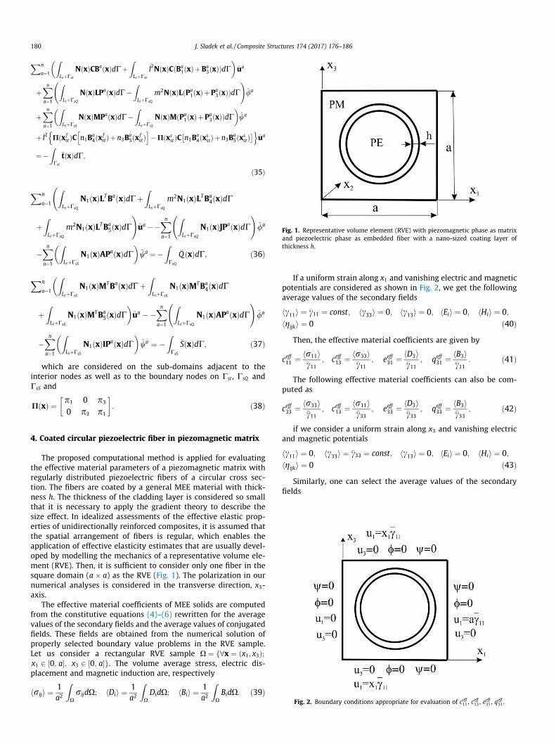
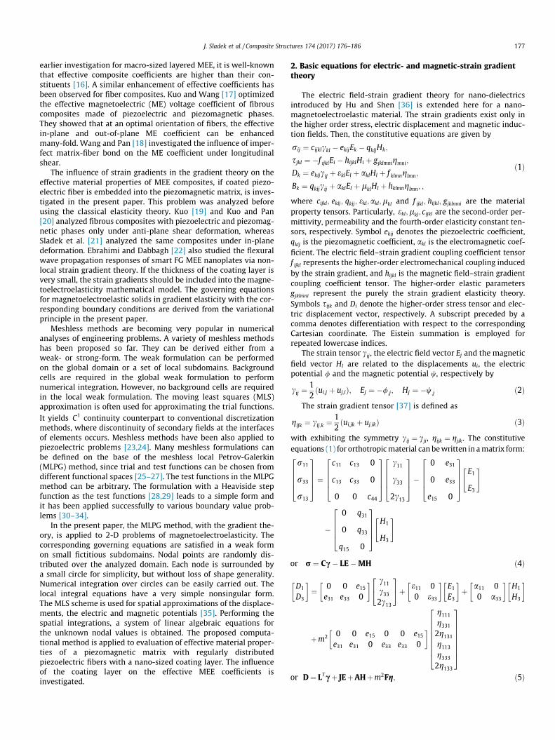
Fig. 1. Representative volume element (RVE) with piezomagnetic phase as matrixand piezoelectric phase as embedded fiber with a nano-sized coating layer ofthickness h.
180 J. Sladek et al. / Composite Structures 174 (2017) 176–186
Xn
a¼1
ZLsþCst
NðxÞCBaðxÞdCþZLsþCst
l2NðxÞCðBa1ðxÞþBa
3ðxÞÞdC� �
ua
þXna¼1
ZLsþCsQ
NðxÞLPaðxÞdC�ZLsþCsQ
m2NðxÞLðPa1ðxÞþPa
3ðxÞÞdC !
/a
þXna¼1
ZLsþCsS
NðxÞMPaðxÞdC�ZLsþCsS
NðxÞMðPa1ðxÞþPa
3ðxÞÞdC� �
wa
þ l2 Pðx fstÞC n1B
a4ðx f
stÞþn3Ba5ðx f
stÞh i
�PðxsstÞC n1B
a4ðxs
stÞþn3Ba5ðxs
st� �n o
ua
¼�ZCst
�tðxÞdC;
ð35Þ
Xn
a¼1
ZLsþCsQ
N1ðxÞLTBaðxÞdCþZLsþCsQ
m2N1ðxÞLTBa4ðxÞdC
þZLsþCsQ
m2N1ðxÞLTBa5ðxÞdC
!ua ��
Xna¼1
ZLsþCsQ
N1ðxÞJPaðxÞdC !
/a
�Xna¼1
ZLsþCsS
N1ðxÞAPaðxÞdC� �
wa ¼�ZCsQ
�QðxÞdC; ð36Þ
Xn
a¼1
ZLsþCsS
N1ðxÞMTBaðxÞdCþZLsþCsS
N1ðxÞMTBa4ðxÞdC
�
þZLsþCsS
N1ðxÞMTBa5ðxÞdC
�ua ��
Xna¼1
ZLsþCsQ
N1ðxÞAPaðxÞdC !
/a
�Xna¼1
ZLsþCsS
N1ðxÞIPaðxÞdC� �
wa ¼ �ZCsS
�SðxÞdC; ð37Þ
which are considered on the sub-domains adjacent to theinterior nodes as well as to the boundary nodes on Cst , CsQ andCsS and
PðxÞ ¼ p1 0 p3
0 p3 p1
� �: ð38Þ
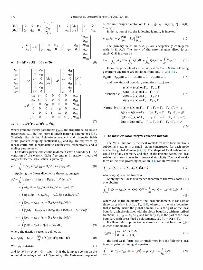
Fig. 2. Boundary conditions appropriate for evaluation of ceff , ceff , eeff , qeff .
4. Coated circular piezoelectric fiber in piezomagnetic matrix
The proposed computational method is applied for evaluatingthe effective material parameters of a piezomagnetic matrix withregularly distributed piezoelectric fibers of a circular cross sec-tion. The fibers are coated by a general MEE material with thick-ness h. The thickness of the cladding layer is considered so smallthat it is necessary to apply the gradient theory to describe thesize effect. In idealized assessments of the effective elastic prop-erties of unidirectionally reinforced composites, it is assumed thatthe spatial arrangement of fibers is regular, which enables theapplication of effective elasticity estimates that are usually devel-oped by modelling the mechanics of a representative volume ele-ment (RVE). Then, it is sufficient to consider only one fiber in thesquare domain (a � a) as the RVE (Fig. 1). The polarization in ournumerical analyses is considered in the transverse direction, x3-axis.
The effective material coefficients of MEE solids are computedfrom the constitutive equations (4)–(6) rewritten for the averagevalues of the secondary fields and the average values of conjugatedfields. These fields are obtained from the numerical solution ofproperly selected boundary value problems in the RVE sample.Let us consider a rectangular RVE sample X ¼ f8x ¼ ðx1; x3Þ;x1 2 ½0; a�; x3 2 ½0; a�g. The volume average stress, electric dis-placement and magnetic induction are, respectively
hriji ¼ 1a2
ZXrijdX; hDii ¼ 1
a2
ZXDidX; hBii ¼ 1
a2
ZXBidX: ð39Þ
If a uniform strain along x1 and vanishing electric and magneticpotentials are considered as shown in Fig. 2, we get the followingaverage values of the secondary fields
hc11i ¼ �c11 ¼ const; hc33i ¼ 0; hc13i ¼ 0; hEii ¼ 0; hHii ¼ 0;hgijki ¼ 0 ð40Þ
Then, the effective material coefficients are given by
ceff11 ¼ hr11i�c11
; ceff13 ¼ hr33i�c11
; eeff31 ¼ hD3i�c11
; qeff31 ¼ hB3i
�c11: ð41Þ
The following effective material coefficients can also be com-puted as
ceff33 ¼ hr33i�c11
; ceff13 ¼ hr11i�c33
; eeff33 ¼ hD3i�c33
; qeff33 ¼ hB3i
�c33; ð42Þ
if we consider a uniform strain along x3 and vanishing electricand magnetic potentials
hc11i ¼ 0; hc33i ¼ �c33 ¼ const; hc13i ¼ 0; hEii ¼ 0; hHii ¼ 0;hgijki ¼ 0 ð43Þ
Similarly, one can select the average values of the secondaryfields
11 13 31 31

J. Sladek et al. / Composite Structures 174 (2017) 176–186 181
hc11i ¼ 0; hc33i ¼ 0; hc13i ¼ �c13 ¼ const; hEii ¼ 0; hHii ¼ 0;hgijki ¼ 0 ð44Þto compute effective material coefficients
ceff66 ¼ hr13i2�c13
; eeff15 ¼ hD1i2�c13
; qeff15 ¼ hB1i
2�c13: ð45Þ
If a uniform electric intensity field along x3 and vanishing dis-placements are considered, the average values of the secondaryfields are given as
hc11i ¼ 0; hc33i ¼ 0; hc13i ¼ 0; hEii ¼ �E3di3 ¼ const; hHii ¼ 0;hgijki ¼ 0 ð46Þ
Then, one can calculate the following effective materialcoefficients
eeff31 ¼ �hr11i�E3
; eeff33 ¼ �hr33i�E3
; eeff33 ¼ hD3i�E3
; aeff33 ¼ hB3i
�E3: ð47Þ
Similarly, a uniform electric intensity field along x1 and vanish-ing displacements are considered
hc11i ¼ 0; hc33i ¼ 0; hc13i ¼ 0; hEii ¼ �E1di1 ¼ const; hHii ¼ 0;hgijki ¼ 0 ð48Þ
for evaluating the effective material coefficients
eeff11 ¼ hD1i�E1
; eeff15 ¼ �hr13i�E1
; aeff11 ¼ hB1i
�E1: ð49Þ
If the following boundary conditions are considered
hc11i ¼ 0; hc33i ¼ 0; hc13i ¼ 0; hEii ¼ 0; hHii ¼ �H1di1 ¼ const;
hgijki ¼ 0 ð50Þthe effective material coefficients are computed as
qeff15 ¼ �hr13i
�H1; aeff
11 ¼ hD1i�H1
; leff11 ¼ hB1i
�H1: ð51Þ
Finally, if the average values of the secondary fields are consid-ered as
hc11i ¼ 0; hc33i ¼ 0; hc13i ¼ 0; hEii ¼ 0; hHii ¼ �H3di3 ¼ const;
hgijki ¼ 0 ð52Þthen, we can calculate the following effective material
coefficients
qeff31 ¼ �hr11i
�H3; qeff
33 ¼ �hr33i�H3
; aeff33 ¼ hD3i
�H3; leff
33 ¼ hB3i�H3
: ð53Þ
where the volume average values of the conjugated fields hr11i,hr33i, hr13i, hD3i, hB3i are calculated from Eq. (39), with the inte-grands being obtained from the solution of the considered boundaryvalue problem.
5. Numerical examples
In the numerical examples, the RVE has a piezoelectric fiberwith circular cross section in the square domain (a � a). The fiberis coated by the piezomagnetic material Terfenol-D. The matrixmaterial parameter is CoFe2O4 whose properties are given in[39]. The piezoelectric fiber is BaTiO3 with parameters
c11 ¼ 16:6� 1010 Nm�2; c13 ¼ 7:8� 1010 Nm�2;
c33 ¼ 16:2� 1010 Nm�2; c44 ¼ 4:3� 1010 Nm�2 ;
e15 ¼ 11:6 Cm�2; e31 ¼ �4:4 Cm�2; e33 ¼ 18:6 Cm�2 ;
e11 ¼ 11:2� 10�9 C2=Nm2; e33 ¼ 12:6� 10�9 C2=Nm2;
q15 ¼ 0:0 N=Am; q31 ¼ 0:0 N=Am; q33 ¼ 0:0 N=Am;
a11 ¼ 0:0 Ns=VC; a33 ¼ 0:0 Ns=VC;
l11 ¼ 5:0� 10�6 Ns2 C�2; l33 ¼ 10:0� 10�6 Ns2 C�2 :
The piezomagnetic material Terfenol-D has the following mate-rial coefficients:
c11 ¼ 0:854� 1010 Nm�2; c13 ¼ 0:391� 1010 Nm�2;
c33 ¼ 2:83� 1010 Nm�2 ; c44 ¼ 0:555� 1010 Nm�2 ;
e15 ¼ 0:0 Cm�2; e31 ¼ 0:0 Cm�2 ; e33 ¼ 0:0 Cm�2 ;
e11 ¼ 0:05� 10�9 C2=Nm2; e33 ¼ 0:05� 10�9 C2=Nm2 ;
q15 ¼ 155:5 N=Am; q31 ¼ �5:75 N=Am; q33 ¼ 270:1 N=Am;
a11 ¼ 0:0 Ns=VC; a33 ¼ 0:0 Ns=VC ;
l11 ¼ 8:6� 10�6 Ns2 C�2; l33 ¼ 2:3� 10�6 Ns2 C�2 :
The volume fraction of the fiber is introduced here asf ¼ pr2=a2, with r ¼ r0 þ h where r0 is the radius of the circularcross section of the fiber and h is the coating layer thickness. Thefollowing geometrical dimensions have been considered in thenumerical model: h ¼ 1 � 10�8 m and a ¼ 5 � 10�7m:
The coating layer thickness is kept constant for all the consid-ered volume fractions. Due to the symmetry of the problem withrespect to both Cartesian coordinates, only a quarter of the RVEis modelled. We have used 300 nodes for the MLS approximationof the physical quantities in the fiber and 2414 nodes in the matrix.The quarter of the coating layer is approximated by 90 nodes. Thelocal subdomains are assumed circular.
Now, it is needed to ensure a jump of secondary fields on inter-faces. It is well known that the C1� continuity is ensured over theentire domain in the MLS approximation. Therefore the continuityconditions of the tractions, electric displacement and magneticinduction are satisfied on interfaces too. However, this highly con-tinuous nature leads to difficulties when there is an imposed dis-continuity in the secondary fields. To simulate jumps oninterfaces Krongauz and Belytschko [40] introduced a jump shapefunction for 2-D problems. It is a trial function with a pre-imposeddiscontinuity in the gradient of the function on interfaces. It is verytedious to applied this approach for curvilinear interfaces. Cordesand Moran [41] solved also 2-D problems using Lagrangian multi-plier. The method requires a lot of computational effort for the dis-continuity of a complex geometrical shape.
It is much simpler to apply double nodes approach for the mate-rial discontinuity [42]. Two sets of collocation nodes are assignedon both the +side and the �side of the material interface at thesame location (Fig. 3). The MLS approximations are carried out sep-arately on particular sets of nodes related to the homogeneousdomains. Then, the support domains for the weights in theweighted MLS approximations must be truncated at the interfaceof the two media. Then, the high order continuity is kept withineach homogeneous part, but not across their interface. The localsubdomains considered around nodes should not cross the inter-face too.
On the interface CI , we must enforce the continuity for the dis-placements and potentials, as well as the equilibrium of tractions,electric charge and magnetic flux by collocating the following
equations at double nodes xd 2 @Xds \ CI ¼ Cd
I :
Interface between two media
Medium +Medium -
circular subdomain
semi-circular subdomain for node in +
Fig. 3. Double nodes approach for material discontinuities.
182 J. Sladek et al. / Composite Structures 174 (2017) 176–186
Xnþa¼1
NaðxdÞua ¼Xn�a¼1
NaðxdÞua; ð54Þ
Xnþa¼1
NaðxdÞ/a ¼Xn�a¼1
NaðxdÞ/a; ð55Þ
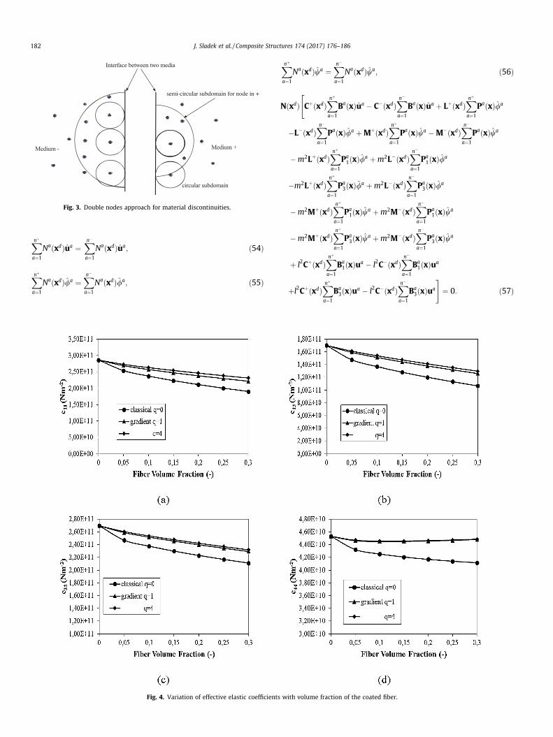
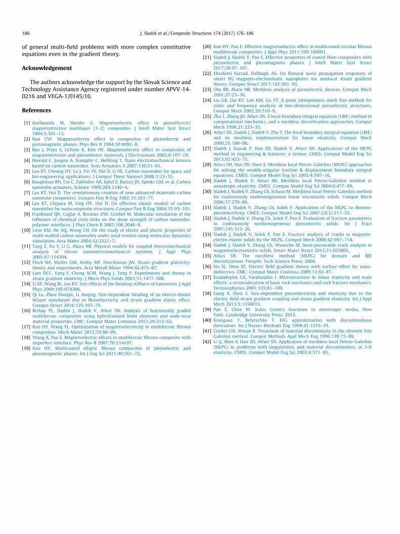
Fig. 4. Variation of effective elastic coefficients
Xnþa¼1
NaðxdÞwa ¼Xn�a¼1
NaðxdÞwa; ð56Þ
NðxdÞ CþðxdÞXnþa¼1
BaðxÞua � C�ðxdÞXn�a¼1
BaðxÞua þ LþðxdÞXnþa¼1
PaðxÞ/a
"
�L�ðxdÞXn�a¼1
PaðxÞ/a þMþðxdÞXnþa¼1
PaðxÞwa �M�ðxdÞXn�a¼1
PaðxÞwa
�m2LþðxdÞXnþa¼1
Pa1ðxÞ/a þm2L�ðxdÞ
Xn�a¼1
Pa1ðxÞ/a
�m2LþðxdÞXnþa¼1
Pa3ðxÞ/a þm2L�ðxdÞ
Xn�a¼1
Pa3ðxÞ/a
�m2MþðxdÞXnþa¼1
Pa1ðxÞwa þm2M�ðxdÞ
Xn�a¼1
Pa1ðxÞwa
�m2MþðxdÞXnþa¼1
Pa3ðxÞwa þm2M�ðxdÞ
Xn�a¼1
Pa3ðxÞwa
þ l2CþðxdÞXnþa¼1
Ba1ðxÞua � l2C�ðxdÞ
Xn�a¼1
Ba1ðxÞua
þl2CþðxdÞXnþa¼1
Ba3ðxÞua � l2C�ðxdÞ
Xn�a¼1
Ba3ðxÞua
#¼ 0: ð57Þ
with volume fraction of the coated fiber.
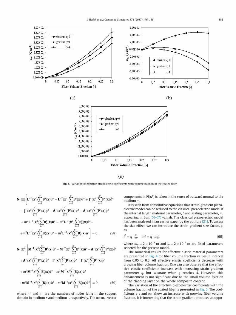
Fig. 5. Variation of effective piezoelectric coefficients with volume fraction of the coated fiber.
J. Sladek et al. / Composite Structures 174 (2017) 176–186 183
N1ðxÞ LþTðxdÞXnþa¼1
BaðxÞua � L�TðxdÞXn�a¼1
BaðxÞua þ JþðxdÞXnþa¼1
PaðxÞ/a
"
� J�ðxdÞXn�a¼1
PaðxÞ/a � AþðxdÞXnþa¼1
PaðxÞwa þ A�ðxdÞXn�a¼1
PaðxÞwa
þm2LþTðxdÞXnþa¼1
Ba4ðxÞua �m2L�TðxdÞ
Xn�a¼1
Ba4ðxÞuaþ
þm2LþTðxdÞXnþa¼1
Ba5ðxÞua �m2L�TðxdÞ
Xn�a¼1
Ba5ðxÞua
#¼ 0; ð58Þ
N1ðxdÞ MþTðxdÞXnþa¼1
BaðxÞua �M�TðxdÞXn�a¼1
BaðxÞua �AþðxdÞXnþa¼1
PaðxÞ/a
"
þA�ðxdÞXn�a¼1
PaðxÞ/a � IþðxdÞXnþa¼1
PaðxÞwa þ I�ðxdÞXn�a¼1
PaðxÞwa
þm2MþTxdXnþa¼1
Ba4ðxÞua �m2M�Txd
Xn�a¼1
Ba4ðxÞua
þm2MþTðxdÞXnþa¼1
Ba5ðxÞua �m2M�TðxdÞ
Xn�a¼1
Ba5ðxÞua
#¼ 0; ð59Þ
where nþ and n� are the numbers of nodes lying in the supportdomain in medium + and medium -, respectively. The normal vector
components in NðxdÞ is taken in the sense of outward normal to themedium +.
It is seen from constitutive equations that strain-gradient piezo-electric model can be reduced to the classical piezoelectric model ifthe internal length material parameter, l, and scaling parameter, m,appearing in Eqs. (5)–(7) vanish. The classical piezoelectric modelhas been analyzed in an earlier paper by the authors [21]. To assessthe size effect, we can introduce the strain-gradient size-factor, q,as
l2 ¼ q � l20; m2 ¼ q �m20; ð60Þ
where m0 ¼ 2� 10�8 m and l0 ¼ 2� 10�9 m are fixed parametersselected for the present model.
The numerical results for effective elastic material parametersare presented in Fig. 4 for fiber volume fraction values in intervalfrom 0.05 to 0.3. All effective elastic coefficients decrease withgrowing fiber volume fraction. One can also observe that the effec-tive elastic coefficients increase with increasing strain gradientparameter q, but saturate when q reaches 4. However, thisenhancement is not significant due to the small volume fractionof the cladding layer on the whole composite content.
The variation of the effective piezoelectric coefficients with thevolume fraction of the coated fiber is presented in Fig. 5. The coef-ficients e15 and e33 show an increase with growing fiber volumefraction. It is interesting that the strain gradient produces an oppo-
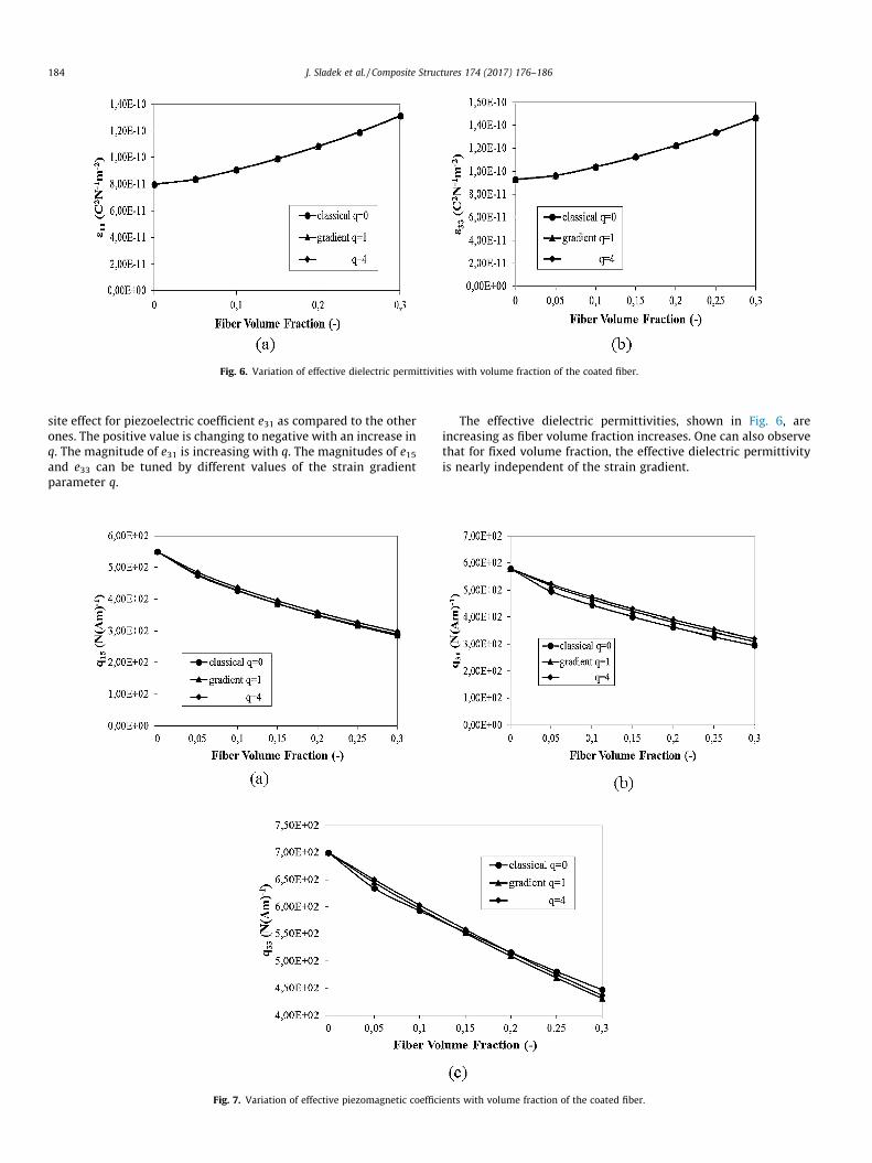
Fig. 6. Variation of effective dielectric permittivities with volume fraction of the coated fiber.
184 J. Sladek et al. / Composite Structures 174 (2017) 176–186
site effect for piezoelectric coefficient e31 as compared to the otherones. The positive value is changing to negative with an increase inq. The magnitude of e31 is increasing with q. The magnitudes of e15and e33 can be tuned by different values of the strain gradientparameter q.
Fig. 7. Variation of effective piezomagnetic coeffic
The effective dielectric permittivities, shown in Fig. 6, areincreasing as fiber volume fraction increases. One can also observethat for fixed volume fraction, the effective dielectric permittivityis nearly independent of the strain gradient.
ients with volume fraction of the coated fiber.

Fig. 8. Variation of effective magnetoelectric coefficients with volume fraction of the coated fiber.
Fig. 9. Variation of effective magnetic permeabilities with volume fraction of the coated fiber.
J. Sladek et al. / Composite Structures 174 (2017) 176–186 185
Variation of the effective piezomagnetic coefficients with thevolume fraction of coated fiber is shown in Fig. 7. The effectivepiezomagnetic coefficients are reduced as the volume fraction ofthe fiber increases. The effect of strain gradients is insignificantfor all effective piezomagnetic coefficients.
Variation of the effective magnetoelectric coefficients with thevolume fraction of the coated fiber is shown in Fig. 8. The magni-tude of these coefficients highly increases as the fiber volume frac-tion increases. One can also observe a strong influence of the straingradient on the effective magnetoelectric coefficients. The effectivemagnetoelectric coefficients are enhanced as compared to the clas-sical models, particularly when q is large.
Finally, Fig. 9 shows the effect of fiber volume fraction on theeffective magnetic permeabilities. Both effective magnetic perme-abilities decrease with increasing volume fraction of the coatedpiezoelectric fiber. The influence of strain gradients on the effectivemagnetic permeabilities is also very small.
6. Conclusions
A new formulation based on the meshless local Petrov-Galerkin(MLPG) method is developed for the evaluation of the effectivematerial properties in MEE composite materials described bythe gradient theory. The strain-gradients are considered in the con-stitutive equations. The composite is made of a piezomagnetic
matrix with embedded piezoelectric fibers with nano-sized coatinglayer. The governing equations with the corresponding boundaryconditions are derived using the variational principle. The localintegral equations for the solution of 2D boundary value problemsof magnetoelectroelasticity are derived in the gradient theory.
It follows from the numerical analyses that the effective elastic,piezoelectric, magnetoelectric coefficients and magnetic perme-abilities are influenced significantly by the strain-gradient. Whilethe effective piezomagnetic coefficients and dielectric permeabili-ties are influenced very weakly. The strongest influence of the clad-ding layer is observed in the effective magnetoelectric (ME)coefficients. The influence of the coating layer on the effectiveME coefficient is dominant although the ME coefficients for allthree composite constituents (fiber, matrix, coating) are zero. Thus,our MLPG modeling results could open an opportunity for enhanc-ing the ME coefficients in coated fiber composites for possiblepromising future applications.
The strain-gradient theory should be employed if the dimen-sions of the analyzed problem are of the same order of magnitudeas the internal material length. Numerical results illustrate thatsize-effect phenomenon must be considered in such cases. TheMLPG method has been successfully applied to nano-MEE compos-ites. The present local integral equation method requires no funda-mental solutions and all integrands in the present formulation areregular. Therefore, the method is promising for numerical analysis
186 J. Sladek et al. / Composite Structures 174 (2017) 176–186
of general multi-field problems with more complex constitutiveequations even in the gradient theory.
Acknowledgement
The authors acknowledge the support by the Slovak Science andTechnology Assistance Agency registered under number APVV-14-0216 and VEGA-1/0145/16.
References
[1] Avellaneda M, Harshe G. Magnetoelectric effect in piezoelectric/magnetostrictive multilayer (2–2) composites. J Intell Mater Syst Struct1994;5:501–13.
[2] Nan CW. Magnetoelectric effect in composites of piezoelectric andpiezomagnetic phases. Phys Rev B 1994;50:6082–8.
[3] Ryu J, Priya S, Uchino K, Kim HE. Magnetoelectric effect in composites ofmagnetostrictive and piezoelectric materials. J Electroceram 2002;8:107–19.
[4] Hierold C, Jungen A, Stampfer C, Helbling T. Nano electromechanical sensorsbased on carbon nanotubes. Sens Actuators A 2007;136:51–61.
[5] Lau KT, Cheung HY, Lu J, Yin YS, Hui D, Li HL. Carbon nanotubes for space andbio-engineering applications. J Comput Theor Nanosci 2008;5:23–35.
[6] Baughman RH, Cui C, Zakhidov AA, Iqbal Z, Barisci JN, Spinks GM, et al. Carbonnanotube actuators. Science 1999;284:1340–4.
[7] Lau KT, Hui D. The revolutionary creation of new advanced materials-carbonnanotube composites. Compos Part B-Eng 2002;33:263–77.
[8] Lau KT, Chipara M, Ling HY, Hui D. On effective elastic moduli of carbonnanotubes for nanocomposite structures. Compos Part B-Eng 2004;35:95–101.
[9] Frankland SJV, Caglar A, Brenner DW, Griebel M. Molecular simulation of theinfluence of chemical cross-links on the shear strength of carbon nanotube-polymer interfaces. J Phys Chem B 2002;106:3046–8.
[10] Liew KM, He XQ, Wong CH. On the study of elastic and plastic properties ofmulti-walled carbon nanotubes under axial tension using molecular dynamicssimulation. Acta Mater 2004;52:2521–7.
[11] Tang Z, Xu Y, Li G, Aluru NR. Physical models for coupled electromechanicalanalysis of silicon nanoelectromechanical systems. J Appl Phys2005;97:114304.
[12] Fleck NA, Muller GM, Ashby MF, Hutchinson JW. Strain gradient plasticity:theory and experiments. Acta Metall Mater 1994;42:475–87.
[13] Lam DCC, Yang F, Chong ACM, Wang J, Tong P. Experiments and theory instrain gradient elasticity. J Mech Phys Solids 2003;51:1477–508.
[14] Li XF, Wang BL, Lee KY. Size effects of the bending stiffness of nanowires. J ApplPhys 2009;105:074306.
[15] Qi Lu, Zhou Shenjie, Li Anqing. Size-dependent bending of an electro-elasticbilayer nanobeam due to flexoelectricity and strain gradient elastic effect.Compos Struct 2016;135:167–75.
[16] Bishay PL, Sladek J, Sladek V, Atluri SN. Analysis of functionally gradedmultiferroic composites using hybrid/mixed finite elements and node-wisematerial properties. CMC: Comput Mater Continua 2012;29:213–62.
[17] Kuo HY, Wang YL. Optimization of magnetoelectricity in multiferroic fibrouscomposites. Mech Mater 2012;50:88–99.
[18] Wang X, Pan E. Magnetoelectric effects in multiferroic fibrous composite withimperfect interface. Phys Rev B 2007;76:214107.
[19] Kuo HY. Multicoated elliptic fibrous composites of piezoelectric andpiezomagnetic phases. Int J Eng Sci 2011;49:561–75.
[20] Kuo HY, Pan E. Effective magnetoelectric effect in multicoated circular fibrousmultiferroic composites. J Appl Phys 2011;109:104901.
[21] Sladek J, Sladek V, Pan E. Effective properties of coated fiber-composites withpiezoelectric and piezomagnetic phases. J Intell Mater Syst Struct2017;28:97–107.
[22] Ebrahimi Farzad, Dabbagh Ali. On flexural wave propagation responses ofsmart FG magneto-electroelastic nanoplates via nonlocal strain gradienttheory. Compos Struct 2017;162:281–93.
[23] Ohs RR, Aluru NR. Meshless analysis of piezoelectric devices. Comput Mech2001;27:23–36.
[24] Liu GR, Dai KY, Lim KM, Gu YT. A point interpolation mesh free method forstatic and frequency analysis of two-dimensional piezoelectric structures.Comput Mech 2002;29:510–9.
[25] Zhu T, Zhang JD, Atluri SN. A local boundary integral equation (LBIE) method incomputational mechanics, and a meshless discretization approaches. ComputMech 1998;21:223–35.
[26] Atluri SN, Sladek J, Sladek V, Zhu T. The local boundary integral equation (LBIE)and its meshless implementation for linear elasticity. Comput Mech2000;25:180–98.
[27] Sladek J, Stanak P, Han ZD, Sladek V, Atluri SN. Applications of the MLPGmethod in engineering & Sciences: a review. CMES: Comput Model Eng Sci2013;92:423–75.
[28] Atluri SN, Han ZD, Shen S. Meshless local Petrov-Galerkin (MLPG) approachesfor solving the weakly-singular traction & displacement boundary integralequations. CMES: Comput Model Eng Sci 2003;4:507–16.
[29] Sladek J, Sladek V, Atluri SN. Meshless local Petrov-Galerkin method inanisotropic elasticity. CMES: Comput Model Eng Sci 2004;6:477–89.
[30] Sladek J, Sladek V, Zhang Ch, Schanz M. Meshless local Petrov-Galerkin methodfor continuously nonhomogeneous linear viscoelastic solids. Comput Mech2006;37:279–89.
[31] Sladek J, Sladek V, Zhang Ch, Solek P. Application of the MLPG to thermo-piezoelectricity. CMES: Comput Model Eng Sci 2007;22(3):217–33.
[32] Sladek J, Sladek V, Zhang Ch, Solek P, Pan E. Evaluation of fracture parametersin continuously nonhomogeneous piezoelectric solids. Int J Fract2007;145:313–26.
[33] Sladek J, Sladek V, Solek P, Pan E. Fracture analysis of cracks in magneto-electro-elastic solids by the MLPG. Comput Mech 2008;42:697–714.
[34] Sladek J, Sladek V, Zhang Ch, Wunsche M. Semi-permeable crack analysis inmagnetoelectroelastic solids. Smart Mater Struct 2012;21:025003.
[35] Atluri SN. The meshless method (MLPG) for domain and BIEdiscretizations. Forsyth: Tech Science Press; 2004.
[36] Hu SL, Shen SP. Electric field gradient theory with surface effect for nano-dielectrics. CMC: Comput Mater Continua 2009;13:63–87.
[37] Exadaktylos GE, Vardoulakis I. Microstructure in linear elasticity and scaleeffects: a reconsideration of basic rock mechanics and rock fracture mechanics.Tectonophysics 2001;335:81–109.
[38] Liang X, Shen S. Size-dependent piezoelectricity and elasticity due to theelectric field-strain gradient coupling and strain gradient elasticity. Int J ApplMech 2013;5:1350015.
[39] Pan E, Chen W. Static Green’s functions in anisotropic media. NewYork: Cambridge University Press; 2015.
[40] Krongauz Y, Belytschko T. EFG approximation with discontinuitousderivatives. Int J Numer Methods Eng 1998;41:1215–33.
[41] Cordes LW, Moran B. Treatment of material discontinuity in the element freeGalerkin method. Comput Methods Appl Mech Eng 1996;139:75–89.
[42] Li Q, Shen S, Han ZD, Atluri SN. Application of meshless local Petrov-Galerkin(MLPG) to problems with singularities, and material discontinuities, in 3-Delasticity. CMES: Comput Model Eng Sci 2003;4:571–85.