Embed Size (px)
Citation preview

Evaluation of Foundation on Soil with Cavities:
A Case Study from the UAE
Civil Engineering Department, Abu Dhabi University, Abu Dhabi, United Arab Emirates
Email: [email protected]
Eng. Muhanad Airan Civil Engineering Department, ALHOSN University, Abu Dhabi, United Arab Emirates
Email: [email protected]
Abstract—Abu Dhabi, the capital of United Arab Emirates
(UAE), is one of the most rapidly developing cities during
the last two decades. One of the major problems facing this
rapid development is the presence of sub surface cavities
and sinkholes in different areas of Abu Dhabi, which causes
many engineering and geotechnical problems. The main
objective of this research is to evaluate different foundation
options for a case study from the UAE with foundation on
soil with cavities. The evaluation will be carried out through
a finite element numerical investigation using Plaxis 3D to
model the four proposed foundation options for the selected
case study. The foundation options evaluated are the raft
foundation and the pile foundation first with no cavity
treatment and then with cavity treatment. Based on the
numerical investigation results, the pile foundation with
grouted cavities option is recommended to be used as the
foundation of the studied structure.
Index Terms—Soil Cavity, Numerical Modeling, Plaxis 3D,
Raft Foundation, Pile Foundation
I. INTRODUCTION
Ground cavities are geologic features that result from
water erosion in soluble rocks over time due to seasonal
ground variation and/or ground water flow and the
associated seepage forces. These cavities represent a
serious geotechnical hazard for civil construction and
urban development [1]. The procedure of cavity creation,
extension and spread is hard to anticipate in light of the
fact that it is driven by a blend of different scenarios
depending on local geological conditions such as the
dissolution rate of rock, flow of groundwater, amount of
fine material within rock layers, presence of loose,
uncontrolled fill over the rock and the leakage of
underground utilities. In United Arab Emirates (UAE),
Abu Dhabi most cavities occur in mudstone or gypsum,
or at an interface between these two rock types [2].
For the past few years, UAE has been experiencing
significant growth of urbanization outside the city center
of Abu Dhabi, due to the population explosion that
happened in a short period of time. This is accompanied
with the discovery of cavities in Shakhbout City, Zayed
Manuscript received December 6, 2017; revised August 25, 2018.
City, Al Falah and the regions around Abu Dhabi
International Airport which is located a few kilometers
far from the city center as shown in Fig.1 [3, 4].
Figure 1. Cavity distribution in Abu Dhabi City [3].
The majority of cavities in Abu Dhabi (67%) were
detected in Shakbout area where the risk posed by the
presence of cavities is considered real, as villas and roads
have been heavily damaged due to ground collapse and
sinkhole formation. Fig. 2 shows two examples of
damaged structures in Abu Dhabi due to presence of
underground cavities.
Figure 2. Damaged structures in Abu Dhabi due to presence of underground cavities: a) Fence of a villa and b) Asphalt road.
a)
b)
358
International Journal of Structural and Civil Engineering Research Vol. 7, No. 4, November 2018
© 2018 Int. J. Struct. Civ. Eng. Res.doi: 10.18178/ijscer.7.4.358-363
Reem Sabouni
The surface layers in this region are classified as fill
that consists of very loose-to-very dense silty sand
underlain by deep interlayer formations of very weak to
moderately strong gypsum and mudstone [3].
II. THE CASE STUDY
A structure with cavity problems was picked to study
different foundation options through a numerical
investigation using the finite element method. The results
of this investigation are used to choose the most efficient
foundation. The studied structure is an indoor
multipurpose sports hall of a private school located in
Shakhbout City in Abu Dhabi (See Fig. 3). By using
Plaxis 3D, four foundations options are studied in this
investigation which are raft foundation with no cavity
treatment, raft foundation with grouted cavities, pile
foundation with no cavity treatment and pile foundation
with grouted cavities. The four options are assessed,
compared and then a recommendation for the foundation
is made.
Figure 3. Multipurpose sports hall (817m2) [5].
The investigated site is at Shakhbout City, Abu Dhabi.
The strata characteristic of this area is dominated by
Aeolian dune sand, Sabkha and evaporates deposits of
Holocene to Pleistocene age. The dune sand deposits
typically comprise fine-grained silty calcareous sand,
which is commonly mobile layer. Although variable, the
degree of cementation generally increases with depth,
such that the variable cemented sand grades to
predominantly calcareous sandstone. Very silty,
gypsiferous Sabkha and evaporate layers commonly
occur within the Aeolian sand deposits. Sabkha layers,
where present, tend to occur from the surface of shallow
depth [5].
The soil properties were found from interpretation of
the results of both the geotechnical and the geophysical
investigation. The geotechnical investigation presented
the information on three boreholes drilled down to a
depth of 30 m below the existing ground surface at the
location of the sports hall. The findings of the drilled
boreholes indicate that the materials encountered at the
site were generally consistent with the general geology of
the area. Moreover, a partial disappear of gypsum layer
was encountered in one of the boreholes from -11.5 m to
-12 m which indicate a presence of a cavity at this region.
This borehole was selected to be used in Plaxis 3D in
order to represent the soil layers with their sequence in
addition to the groundwater level which is equal to 4.9 m
below the ground surface. The soil layers from top to
bottom are: silty sand, sand, gypsum, and mudstone as
shown in Fig. 5 [5].
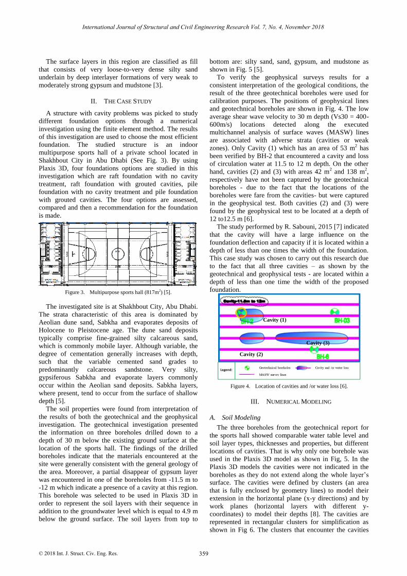
To verify the geophysical surveys results for a
consistent interpretation of the geological conditions, the
result of the three geotechnical boreholes were used for
calibration purposes. The positions of geophysical lines
and geotechnical boreholes are shown in Fig. 4. The low
average shear wave velocity to 30 m depth (Vs30 = 400-
600m/s) locations detected along the executed
multichannel analysis of surface waves (MASW) lines
are associated with adverse strata (cavities or weak
zones). Only Cavity (1) which has an area of 53 m2 has
been verified by BH-2 that encountered a cavity and loss
of circulation water at 11.5 to 12 m depth. On the other
hand, cavities (2) and (3) with areas 42 m2 and 138 m
2,
respectively have not been captured by the geotechnical
boreholes - due to the fact that the locations of the
boreholes were fare from the cavities- but were captured
in the geophysical test. Both cavities (2) and (3) were
found by the geophysical test to be located at a depth of
12 to12.5 m [6].
The study performed by R. Sabouni, 2015 [7] indicated
that the cavity will have a large influence on the
foundation deflection and capacity if it is located within a
depth of less than one times the width of the foundation.
This case study was chosen to carry out this research due
to the fact that all three cavities – as shown by the
geotechnical and geophysical tests - are located within a
depth of less than one time the width of the proposed
foundation.
Figure 4. Location of cavities and /or water loss [6].
III. NUMERICAL MODELING
A. Soil Modeling
The three boreholes from the geotechnical report for
the sports hall showed comparable water table level and
soil layer types, thicknesses and properties, but different
locations of cavities. That is why only one borehole was
used in the Plaxis 3D model as shown in Fig, 5. In the
Plaxis 3D models the cavities were not indicated in the
boreholes as they do not extend along the whole layer’s
surface. The cavities were defined by clusters (an area
that is fully enclosed by geometry lines) to model their
extension in the horizontal plane (x-y directions) and by
work planes (horizontal layers with different y-
coordinates) to model their depths [8]. The cavities are
represented in rectangular clusters for simplification as
shown in Fig 6. The clusters that encounter the cavities
Cavity (1)
Cavity (2)
Cavity (3)
359
International Journal of Structural and Civil Engineering Research Vol. 7, No. 4, November 2018
© 2018 Int. J. Struct. Civ. Eng. Res.

are deactivated between the plans that contain the cavities
when the analysis is performed. The locations of the
modeled cavities are as shown in Fig.6. Cavity (1) is
located at a depth of 11.5m to 12m and cavities (2) and (3)
are located at a depth of 12m to 12.5m.
Figure 5. The soil layers of the calibrated borehole.
The soils parameters used in the Plaxis 3D model are
presented in Table I. The material behavior of all
modeled soil layers was assumed to be drained. The
Mohr-coulomb material model was used for all the
modeled soils.
TABLE I. SOIL AND GROUT PARAMETERS [5].
Parameter
Name
Silty
Sand Sand Gypsum Mudstone Grout
Type Porous Porous Porous Porous Non-
Porous
γunsat [kN/m3] 18.8 24 19 18 24
γsat [kN/m3] 19.5 27 20 20 -
Eref [kN/m2] 13000 15000 100000. 15000 2.5x10⁷
v 0.3 0.3 0.3 0.3 0.2
Cref [kN/m2] 12 1 100 1.00E-03 1
φ [°] 23 32 30 25 30
[°] 0 2 0 0 °
B. Foundation Modeling
Through using Plaxis 3D Foundation, one
comprehensive model that contains both raft and pile
foundation elements (raft, pile caps, ground beams and
piles) was developed (shown in Fig. 6) to run the analysis
of the four foundation options. Using the stage
construction option in Plaxis 3D four foundation and soil
treatment options were generated through activation and
deactivation of soil layers and structural elements during
the analysis stage. The first two options a raft foundation
was used as the foundation system were in the first option
the soil cavities were not treated and the second option
the soil cavity was treated with grout injection. For the
third and fourth options a pile foundation system was
used once with no treatment for the soil cavities and the
other with grout injection treatment for the cavity,
respectively. The grout was modeled by assigning a grout
material type to the deactivated cavity cluster throughout
the layers that encounter the cavity. The grout properties
are shown in Table I.
The raft foundation was modeled with a thickness of
65 cm and had a width and length of 19m and 45m,
respectively. The pile foundation was modeled to match
the pile foundation design details including the piles the
pile caps and the ground beams as shown in Fig.6. The
used properties of all the structural elements (Raft
foundation, pile, pile caps and ground beams) in the
Plaxis 3D model are summarized in Table II.
The model boundaries in the horizontal directions were
taken to be twice the foundation width away from each
edge of the foundation. The depth of the soil model was
extended to three times the foundation width from the tip
of the piles.
C. Structural Load
The applied loads on the foundation were found from
the concentrated loads at the supports of the sports hall
columns and are shown in the SAFE model in Fig. 7. The
same loads were applied to the four studied foundation
options.
TABLE II.
PARAMETERS OF THE STRUCTURAL ELEMENTS [9].
Parameter Name
Raft Foundation
Pile
Pile Cap
Ground Beam
Model
Linear-elastic
Linear-elastic
Linear-elastic
Linear-elastic
γunsat
[kN/m3]
24
24
-
-
A
[m2]
-
-
-
0.78
V
0.2
0.15
0.15
0.1
d
[m]
0.65
-
1.2
-
γ
[kN/m3]
24
-
24
78.5
G
[kN/m2]
1.25E+07
-
1.30E+07
-
Eref
[kN/m2]
3.00E+07
2.92E+07
3.00E+07
3.00E+07
I2
[m4]
-
-
-
1.31E-04
I3
[m4]
-
-
-
1.37E-03
I
[m4]
-
-
-
0
Sil
ty S
an
d
San
d
Gyp
sum
M
ud
ston
e
360
International Journal of Structural and Civil Engineering Research Vol. 7, No. 4, November 2018
© 2018 Int. J. Struct. Civ. Eng. Res.

Figure 6. Top view of a comprehensive model.
Figure 7. Concentrated load values in KN from the SAFE model.
IV. RESULTS AND DISCUSSION
The aim of this research is to study different
foundations options available for structures on cavities to
select the most efficient and safe foundation based on the
results of the extreme total displacement of the studded
foundation options.
A. Raft Foundation with No Cavity Treatment
In raft foundation phases all the loads applied equally
distributed with a value of -140.700 KN/m2 at work plan
y = -1.95 m (the surface of the raft foundation). As shown
in Fig. 8, the resulted extreme total displacement is equal
to 34.6 cm which is very high and can cause severe
damages to the structure.
Figure 8. Shading of total displacement.
B. Raft Foundation with Cavity Treatment
In the raft foundation with cavities that were treated
with grout injection (Fig. 9), the extreme total
displacement is equal to 28.3 cm. In this option the total
displacement has slightly reduced due to filling the three
cavities with grout as shown in the figure below.
Figure 9. View of the raft foundation with grout (some soil layers were removed to show the grouted cavities in gray color).
C. Pile Foundation with No Cavity Treatment
In the case of pile foundation with no cavity treatment,
the extreme total displacement is 30.24 cm as shown in
the Fig. 10. The current option shows larger settlement
than the raft foundation with cavity treatment; this is due
Cavity (1)
Cavity (2) Cavity (3)
Ground Beam
Raft Cluster
Pile
Pile Cap
361
International Journal of Structural and Civil Engineering Research Vol. 7, No. 4, November 2018
© 2018 Int. J. Struct. Civ. Eng. Res.

to the heavy weight of the pile foundation compared to
the raft foundation. The load of the structure has been
applied directly at the top of the piles to avoid any failure
in the structural elements that might affect the result of
the study.
Figure 10. Shading of total displacement (some layers were removed to show the distribution of the piles within soil profile).
D. Pile Foundation with Cavity Treatment
For this option, the extreme total displacement of the
pile foundation with grouted cavities was found to be
11.62 cm (see Fig.11). This option gives the best resistant
to settlement compared with the previous options.
Figure 11. Shading of total displacement at soil ground level.
E. Comparison of the Options
All the four studded options showed no structural
failure or soil collapse. The results of the three first
options showed excessive displacements. The
displacement in the fourth option was largely reduced
when the grout was used with the pile foundation option.
This value is still considered to be somewhat high. This
can be attributed to the fact that the worst case scenario
was considered in the model. Where both modeled
cavities (2) and (3) where indicated in the geophysical
test to be week layer and could not be verified by the
geotechnical test if they are cavities or week soil so they
were taken as cavities. Moreover, the settlement also can
be lowered to a considerable value by using light weight
concrete or by modifying the pile design.
A point that should be kept in mind when choosing a
foundation option including grout treatment, is that
cavities can grow and expand to form cavity networks
which will make cavity grout treatment extremely
expensive.
V. CONCLUSION
Underground cavity problems have been one of the
major problems faced by geotechnical engineers when
designing foundations for structures. In this paper, an
indoor multipurpose sports hall resting on soil with three
cavities located at a relatively shallow depth was chosen
to carry out this study. This structure is located in
Shakhbout City in Abu Dhabi, UAE. Four foundations
options are modeled using the finite element analysis
program Plaxis 3D and studied in this investigation.
These options are: raft foundation with no cavity
treatment, raft foundation with grouted cavities, pile
foundation with no cavity treatment and pile foundation
with grouted cavities. Based on the results of this study,
the pile foundation with grouted cavities was
recommended to be used as the foundation of this
structure. This research will be extended further in the
coming stage to incorporate several other case studies
from a number of locations in the Abu Dhabi city that
encounter the presence of sub surface cavities and
sinkholes. This will be done in order to enable the
researcher to come up with a more comprehensive
recommendation for these areas.
REFERENCES
[1] Beynen, P. E. Van. Karst Management. New York: Springer, 2011.
[2] El Ganainy, M. M. Demirkan, J. J. Gutierrez, et al. Geotechnical
and Geological Engineering, vol. 34, p. 125, 2016. [3] R. Ramanathan, Y. Gao, M. M. Demirkan, B. Hatipoglu, M. E.
Adib, M. Rosenmeier, J. J. Gutierrez, and H. El Ganainy,
“Development of cavity probability map for Abu Dhabi. Municipality Using GIS and Decision Tree Modeling,” Published
in the proceeding of the 14TH Multidisciplinary Conference on Sinkhole and the Engineering and Environmental Impacts of Karst,
NCKRI SYMPOSIUM 5, Rochester, Minnesota, pages 277-288,
5-9 October 2015. [4] R. Ramanathan, Y. Gao, M. M. Demirkan, B. Hatipoglu, M. E.
Adib, M. Rosenmeier, J. J. Gutierrez, and H. El Ganainy,
“Evaluation of cavity distribution using point-pattern analysis,”
Published in the proceeding of the 14TH Multidisciplinary
Conference on Sinkhole and the Engineering and Environmental Impacts of Karst, NCKRI SYMPOSIUM 5, Rochester, Minnesota,
pages 289-298, 5-9 October 2015. [5] Laboratories, Baynunah. "Geotechnical investigation report,"
Private School. Abu Dhabi, January 15, 2014.
[6] Consultancy, Orbit. "Geophysical investigation report," Private School. Abu Dhabi, September 21, 2014.
[7] R. Sabouni, “Displacement and effective stresses changes underneath strip footing on stiff ground with single and double
voids,” Published in the proceeding of GeoMontreal 2013
Conference, Montreal, Canada, 29th October - 3rd September, 2013.
[8] P. E. Brinkgreve, Plaxis 3D Foundation Tutorial Manual version 1, Delft: Plaxis, 1998.
[9] Medhat, Sarah, "Piling and shoring division," Foundation Design.
Abu Dhabi: Australian Piling Technology (L.L.C.), April 8, 2014.
362
International Journal of Structural and Civil Engineering Research Vol. 7, No. 4, November 2018
© 2018 Int. J. Struct. Civ. Eng. Res.

Reem Sabouni is an Associate professor at Abu Dhabi University (ADU) in United Arab
Emirates (UAE) with several publications in
the fields of geotechnical and structural engineering. Prior to her joining ADU Dr.
Reem Sabouni held the position of Chair of the Civil Engineering Department and
Director of University Laboratories at
ALHOSN University in UAE. She is a member of several prominent professional
engineering societies, such as the CGCE, CSCE, ASCE, ACI and is the Chair of Women Engineers in the Fib-
UAE Chapter.
Dr. Reem acquired her PhD and Master degree in Civil Engineering from the University of Western Ontario in Canada. She was the first
researcher in North America to conduct full scale tests on circular precast concrete manholes in a controlled laboratory environment.
These tests were conducted in the Large Scale Geotechnical Testing
Facility in the University of Western Ontario and in collaboration with the Ontario Concrete Pipe Association.
Dr. Reem received several Canadian awards and research scholarships, including the Industrial NSERC Scholarship, the Ontario
Graduate Scholarship, the University President Scholarship, and the
prestigious Milos Novak Memorial. She had also received the Excellence Award from H.H. Sheikha Fatima Bint Mubarak, for
ranking first in the UAE University’s Class of 2002.
363
International Journal of Structural and Civil Engineering Research Vol. 7, No. 4, November 2018
© 2018 Int. J. Struct. Civ. Eng. Res.