Embed Size (px)
Citation preview
FAA Joint Advanced Materials & Structures (JAMS) Center of Excellence 6th Annual Technical Review Meeting, May 19–20, 2010
Burford, et al. Page 1
Evaluation of Friction Stir Weld Process and Properties for Aerospace Application:
e-NDE for Friction Stir Processes
D. Burford, P. Gimenez Britos, E. Boldsaikhan, and J. Brown National Institute for Aviation Research,
Wichita State University, Wichita, KS E-mail: [email protected]
Abstract
A powerful new friction stir welding e-NDE technique, which is based on process
monitoring, shows promise for increasing the accuracy and precision of probability of
detection (POD) analyses when compared to conventional inspection techniques. The
technique is based primarily on monitoring the Fy (transverse) force feedback signal,
which has previously been correlated with defect formation. As an e-NDE near real-
time inspection technique, force feedback process monitoring adds a second layer of
“greenness” to an already extremely “green” process by reducing and potentially elimi-
nating the need for secondary inspection operations like X-ray, and ultrasonic inspection
steps. In terms of establishing standards and specifications for friction stir technologies,
the e-NDE technique featured in this paper will greatly facilitate the establishment of
performance based specifications for FSW that will ultimately become the basis of de-
veloping design data for FSW joints in multiple structures made from multiple alloys and
product forms.
FAA Joint Advanced Materials & Structures (JAMS) Center of Excellence 6th Annual Technical Review Meeting, May 19–20, 2010
Burford, et al. Page 2
Introduction
Successful implementation of friction stir welding (FSW) is reliant upon basic metal-
working principles applied and controlled at a local level.1 The thermal and mechanical
mechanisms involved in FSW are similar to those found in other metal working proc-
esses such as rolling, extruding, and forging. However, unlike these bulk thermo-
mechanical (TM) processing operations, the highly localized nature of FSW introduces
steep thermal and deformation gradients into the material adjacent to and along the joint
line. Therefore, standards and specifications for friction stir technologies must of ne-
cessity address and account for the localized metal working nature of friction stir
technologies.
e-NDE for FSW: In FSW the side of the weld tool is pressed against the workpiece
in a manner similar to that of machining with the side of an end mill. However, unlike
end mill machining, in FSW the tool design and process parameters are selected such
that the displaced material is captured and reconstituted into the original material – as
opposed to removing it from the work zone in the form of “chips” as is done in machin-
ing. Consequently, there are both similarities as well as dramatic differences in the
dynamic response of the respective tools used in end milling and FSW.
In machining, it is important to clear the cut metal (chips) from the tool at a sufficient
rate to prevent clogging of tool features, namely the flutes, etc. In FSW the opposite is
true. The features of a FSW tool, such as threads, grooves, etc., are expected to be-
come impacted with metal – and thereby maintain a full frontal engagement between
the tool and the material of the workpiece – while in machining only the tool cutting
FAA Joint Advanced Materials & Structures (JAMS) Center of Excellence 6th Annual Technical Review Meeting, May 19–20, 2010
Burford, et al. Page 3
edges are expected to be in contact with the workpiece. This full engagement between
the FSW tool and workpiece leads to unique dynamic behavior not typically experienced
in machining.
In machining, advanced control techniques have been investigated for reducing
chatter. For example, Zhang and Sims assessed the ability of “piezoelectric active vi-
bration damping” to arrest chaotic tool behavior.2 To reduce defect formation in FSW
associated with chaotic tool motion, Boldsaikhan,3 and Jene et al.,4 have studied ma-
chine tool-material interactions by monitoring force feedback signals. As these studies
demonstrate, in both machining and FSW, process monitoring may serve as the basis
for reducing chaotic tool behavior and, thereby, provides a means for improving part
quality in both machining and FSW.
In FSW, the tool tends to vibrate or oscillate side-to-side (nominally transverse to
applied loading vector) while under the local dynamic side loading conditions imposed
on the tool at the tool-workpiece interface. In machining, when the tool oscillates in a
chaotic manner, a self-excited vibration phenomenon called “chatter” tends to form,
leaving erratic markings on the newly cut surface. Similar chaotic oscillations in FSW
tend to be associated with the formation of voids within the joint (resulting from the lack
of consistency in the reconsolidation of material along the joint line).
The advancing, rotating FSW tool presses against the material directly ahead of it,
creating a shearing action that extends around the tool front. In a generalized manner,
when the material directly in front of the tool is sufficiently heated under the pressure
and shearing action imposed on it by the advancing FSW tool, thin layers of material are
FAA Joint Advanced Materials & Structures (JAMS) Center of Excellence 6th Annual Technical Review Meeting, May 19–20, 2010
Burford, et al. Page 4
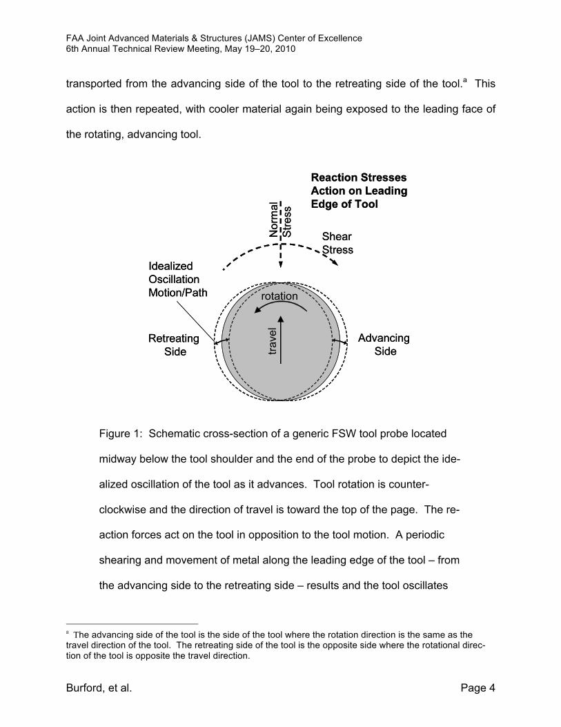
transported from the advancing side of the tool to the retreating side of the tool.a This
action is then repeated, with cooler material again being exposed to the leading face of
the rotating, advancing tool.
Figure 1: Schematic cross-section of a generic FSW tool probe located
midway below the tool shoulder and the end of the probe to depict the ide-
alized oscillation of the tool as it advances. Tool rotation is counter-
clockwise and the direction of travel is toward the top of the page. The re-
action forces act on the tool in opposition to the tool motion. A periodic
shearing and movement of metal along the leading edge of the tool – from
the advancing side to the retreating side – results and the tool oscillates
a The advancing side of the tool is the side of the tool where the rotation direction is the same as the travel direction of the tool. The retreating side of the tool is the opposite side where the rotational direc-tion of the tool is opposite the travel direction.
FAA Joint Advanced Materials & Structures (JAMS) Center of Excellence 6th Annual Technical Review Meeting, May 19–20, 2010
Burford, et al. Page 5
side-to-side (nominally) in response the primary reaction forces acting on
the leading edge of the FSW tool probe.
This new interface or band of material is again pressed upon until it is sufficiently
heated to be moved along the tool front from the advancing side to the retreating side.
This undulation in metal movement along the leading edge of the tool promotes an os-
cillatory or alternating pattern in both normal and shear forces acting on the tool surface,
which in turn causes the tool to move in a periodic motion, nominally side-to-side, as the
tool is advanced. This process is schematically depicted in Figure 1 (depicting only sim-
plified, idealized frontal force conditions).
Material flow and the associated resultant forces acting upon the tool are actually
much more complex than idealized in the model shown in Figure 1.5 With the tool probe
completely submerged in workpiece, forces act on the probe from all directions in re-
sponse to its dynamic loading environment, the resultant of which may be measured
experimentally.6 The full engagement of the rotating, advancing FSW tool further ag-
gravates its tendency to oscillate in a chaotic manner. Adding to the complexity of FSW
tool oscillatory motion is the spinning motion of the tool shoulder face on the surface of
the workpiece. This tends to cause a walking motion of the end of the tool, which even
further promotes chaotic tool behavior as the tool seeks (or seeks to establish) a center
of rotation on the workpiece surface.
Uniformity in FSW tool oscillations is dependent upon the periodicity (or lack thereof)
in the material flow behavior around the tool front. It is anticipated that the lower the
abruptness in the material heating and shearing cycle, the less likely the process will
FAA Joint Advanced Materials & Structures (JAMS) Center of Excellence 6th Annual Technical Review Meeting, May 19–20, 2010
Burford, et al. Page 6
become chaotic in its behavior (action). Selection of tool features and process parame-
ters are expected to contribute to the overall stability of the tool control process.
The ability to monitor the dynamic behavior of FSW tools through force feedback sig-
nals provides an effective way to dramatically reduce or eliminate the inspection costs
associated with secondary inspection techniques such as X-ray, ultrasonic phased array
(UPA), or penetrant inspections. By simply analyzing the force feedback signal of each
weld, this lean and effective e-NDE technique can be utilized to improve production and
quality based directly on recorded weld information. It further offers the potential ability
to actively and adaptively control FSW operations in production. It can also conceivably
be developed to monitor tool wear, optimize design and performance of FSW tools, and
compete different tooling design concepts, etc.
Thermal Components of FSW: The thermal process elements or components of
FSW are typically controlled indirectly (i.e. passively) through the process variables that
most strongly influence them, namely mechanical factors such as spindle speed, travel
speed, and the applied weld tool axial force. Through the influence of these indirect
means, thermal energy is generated during FSW by forcing a rotating, non-consumable
metalworking tool into the joint line between components to be joined. Once stable
processing conditions are established locally, the weld tool is then forcibly translated or
advanced along the joint line to form a consolidated unit.
The energy for conveying material from the advancing to the retreating side of the
weld tool is supplied by the torque and compressive forces of the FSW machine as ap-
plied to the workpiece through the specialized, non-consumable metalworking tool. The
FAA Joint Advanced Materials & Structures (JAMS) Center of Excellence 6th Annual Technical Review Meeting, May 19–20, 2010
Burford, et al. Page 7
actual energy imparted to the workpiece by the machine is converted into heat through
mechanical stirring and frictional/shearing interaction between the non-consumable tool
and workpiece. This heat, which is generated in a local but traveling work zone, can be
viewed conceptually as flowing away from the work zone along three generalized heat
sink paths (or conduits):
Path 1: The Spindle Path: including the metalworking (welding) tool, tool holder,
spindle, machine frame, etc.
Path 2: The Workpiece Path: the workpiece, fixture, machine bed, machine
frame, clamps, connecting structure, etc.
Path 3: The Surroundings Path: the atmosphere, applied materials (coolants,
gases, etc.).
Ideally, the distribution of heat flow away from the localized work zone will remain stable
without either a substantial build-up of heat or a substantial loss of energy as the weld
progresses. The level of heat build-up or loss may shift due to, for example, a local
change in the thermal mass of the part and/or fixture (e.g. at a stiffener or with an in-
crease or decrease in section thickness). Or it may result from traveling at a rate faster
than heat can be dissipated along these three paths collectively.
In practice, the proportion of heat that flows along each of these heat sink paths at
any given time can vary widely. Many factors influence the relative heat flux along each
path. For example, in Path 2, the workpiece path, the flux of heat away from the local
work zone is first regulated by the thermal conductivity and heat capacity of the work-
piece and is then regulated by these same properties of the fixturing and supporting
components (e.g. the backing bar). For regularly shaped parts, where the effective
FAA Joint Advanced Materials & Structures (JAMS) Center of Excellence 6th Annual Technical Review Meeting, May 19–20, 2010
Burford, et al. Page 8
thermal mass cross-section does not vary over the length of the part, a greater probabil-
ity exists that the process will remain stable throughout the duration of the FSW
process. In contrast, in irregularly shaped parts or setups, which vary in thermal mass
along the direction of the weld (e.g. variations in the joint cross-section), joint properties
can vary substantially as a result of the changing thermal environment (heat sink) in and
around the local work zone if not properly accounted for and addressed.
Edge effects also have the potential for contributing to joint property variation. As
the FSW process progresses toward the end of a workpiece, for example, the heat gen-
erated in the part tends to build up near the end of the part where there is a decreasing
amount of material available to contain the heat generated by the advancing tool. Po-
tential approaches for maintaining a consistent thermal environment as the local work
zone nears the end of a part may include changing process parameters to lessen the
heat input into the joint line in the closeout region of the joint.
Rather than attempting to precisely regulate heat flow during FSW, application de-
velopment work is typically based on a phenomenological approach in which process
parameters are developed for each unique setup and welding system.7 Bounding welds
are usually conducted first to identify a suitable process window limit. Then experimen-
tal design techniques (SPC and DOE) are employed to refine the process window for
optimizing selected joint properties. If changes are made to any of the three general
thermal conduits in the system, the process output (e.g. joint material properties) should
be checked to determine what impact, if any, there may have been as a result of the
change. With such an approach, thermal management may be viewed as more of an
art than a science. However, this approach is often justified where a thorough analysis
FAA Joint Advanced Materials & Structures (JAMS) Center of Excellence 6th Annual Technical Review Meeting, May 19–20, 2010
Burford, et al. Page 9
of the setup is not warranted or deemed tractable given the available program re-
sources.
The actual thermal efficiency of a given FSW process, and the gradients associated
with it, may never be well understood or directly controllable. As such, attempting to es-
tablish repeatable processes through a single rigid process specification (e.g. fixing the
setup, tool, process parameters, weld system, etc.) for all applications is not deemed
necessary or even appropriate. Notwithstanding the complexities involved, perform-
ance specifications, along with the appropriate controlling documents (e.g. welding
performance specifications), provide sufficient control to achieve the ultimate process
goal of fabricating structure that meets engineering requirements.
Mechanical Components of FSW: Unlike the thermal components of the FSW proc-
ess, the mechanical components are typically controlled directly through the FSW
machine capabilities and controls, the selection of the metalworking tool and fixture de-
signs, setting processing speeds and feeds, etc. Because process controls can be set
directly through machine settings and tool designs, defining a process specification
around machine controls may seem to be a straightforward approach to establishing
handbook quality data for FSW. However, the steep gradients introduced by FSW
mean that small variations in input (independent) variables (speed, feed, load, tool de-
sign, etc.) can lead to relatively large variations in local response variables (e.g. thermal
gradients, residual stresses, transverse tensile properties).
Therefore, in order to establish usable databases for FSW design data, an under-
standing of potential sources of variation is required and robust methods for managing

FAA Joint Advanced Materials & Structures (JAMS) Center of Excellence 6th Annual Technical Review Meeting, May 19–20, 2010
Burford, et al. Page 10
these inherent variations must be developed. For example, once the basic FSW ma-
chine is selected, an unlimited number of metalworking (weld) tools may be used with it.
Literally hundreds of combinations of geometric features on weld tools are in use today
throughout the various industries utilizing FSW. Shoulder design considerations alone
include a multitude of factors to be established, such as its basic shape (concave, con-
vex, flat, etc.) and the optimum ratio between the shoulder diameter and the probe.
Should the shoulder have scrolls? If so, how many should it have and in what configu-
ration? How deep or wide should they be? Should they be tapered or irregularly
staggered?
The answer to such questions is that there is not one single tooling solution for all
joints, not even for a specific joint. In general, many different tools may be used to pro-
duce the required engineering properties for a given application as long as an optimized
process window is established for each tool on a tool-by-tool basis.9 Further, some
tools may be more sensitive to tool wear and variations in the manufacture of weld tool
features in terms of how they affect the data population generated. Therefore, while it
may be determined how tool design affects joint properties, ultimately, it is more impor-
tant to determine what level of control for a given tool is needed to ensure consistent
joint properties over the life of the tool, as well as between setups, part configurations,
suppliers, etc.
Alloy and workpiece dimensions all come into play when selecting appropriate tool
features and combinations of features. While it may be straightforward to control proc-
essing parameters such as spindle and travel speeds, attempting to control all of the
factors that go into the process is not so straightforward. Different alloys react differ-
FAA Joint Advanced Materials & Structures (JAMS) Center of Excellence 6th Annual Technical Review Meeting, May 19–20, 2010
Burford, et al. Page 11
ently to the possible combinations of features as well. Consider further the fact that
there are numerous patents covering weld tool features. In other words, attempting to
establish process specifications by fixing tool designs, etc., will not lead to the desired
outcome of a controlled process. Specifications must be data and results driven. The
e-NDE technique featured in this paper will greatly facilitate the establishment of per-
formance based specifications for FSW and will ultimately become the basis of
developing design data for FSW joints in multiple structures made from multiple alloys
and product forms.
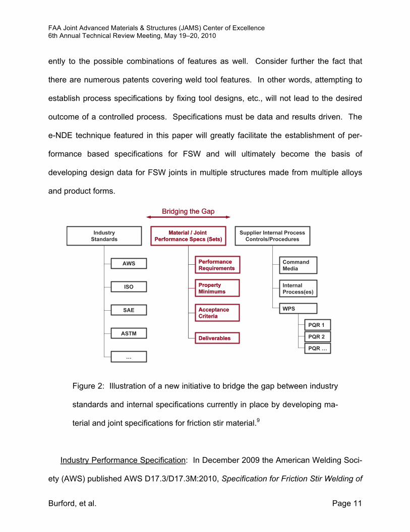
Figure 2: Illustration of a new initiative to bridge the gap between industry
standards and internal specifications currently in place by developing ma-
terial and joint specifications for friction stir material.9
Industry Performance Specification: In December 2009 the American Welding Soci-
ety (AWS) published AWS D17.3/D17.3M:2010, Specification for Friction Stir Welding of
FAA Joint Advanced Materials & Structures (JAMS) Center of Excellence 6th Annual Technical Review Meeting, May 19–20, 2010
Burford, et al. Page 12
Aluminum Alloys for Aerospace Applications.8 While this document provides process
controls and specifications, it does not provide guidance or information regarding ex-
pected joint properties produced by FSW. Specifically, in Section 5.1, Weldment
Design Data, the following statement is made: “The Engineering Authority shall develop
or obtain appropriate material property data to support the weldment design.” There-
fore, each organization relying upon this specification must produce its own material
property data for design.
An initiative to establish performance specifications independent of weld tool design
and process parameters was formerly introduced. 9 Through this initiative, coordination
of material and joint standards was begun through the SAE AMEC committee. As illus-
trated from Figure 2, the objective in establishing SAE sponsored material and joint
specifications is to bridge the gap between industry standards and the internal com-
mand media of individual organizations.
Justification for establishing performance specifications is based on the observation
that FSW has a sufficiently flexible process window that allows all aluminum alloys to be
joined with a wide variety of weld tool designs operated within independently developed
process windows.10,11 Therefore, it was concluded that 1) an unspecified number of tool
designs can be used to make equally sound joints with independently developed proc-
ess windows, 2) any advantage one tool may have over another is expected to be
evident primarily in terms of productivity, i.e. welding and processing speeds, and 3) the
process can be effectively controlled via performance specifications.
Additional observations support the tractability of the path-independence approach.
For example, FSW does not change bulk chemistry (no filler typically added), and it

FAA Joint Advanced Materials & Structures (JAMS) Center of Excellence 6th Annual Technical Review Meeting, May 19–20, 2010
Burford, et al. Page 13
does not involve recasting the alloy (no bulk solid/liquid phase transformation). Joint
properties are observed to be related to parent material mechanical properties (e.g.
strength). They are typically increased in work hardened, non-heat treatable alloys (e.g.
AA5xxx) via grain refinement in the dynamically recrystallized zone (DXZ), i.e. the weld
nugget. They are typically decreased in precipitation-strengthened Al alloys, for exam-
ple, by over-aging in the heat affected zone (HAZ) adjacent to the joint.
Consider aircraft aluminum alloy AA2024-T3 for an example. It may be produced in
one of many ways, including on a continuous rolling line or in a batch facility. Both
product forms may be sold to the same industry specification because the specification
does not explicitly call out the type of rolling stands or the other mechanical equipment
used to process the material thermomechanically. Likewise, extruded and forged mate-
rials come in a variety of shapes and sizes, each requiring its own processing schedule,
but they are still sold to the same material specifications. Even though each piece does
not get exactly the same thermomechanical treatment in production, it may be sold to
common minimum property specifications. Similarly, FSW, developed as a thermome-
chanical process can be expected to produce common minimum property values
independent of the processing steps involved.
Experimental Approach
A Nondestructive Evaluation (NDE) inspection round robin was conducted on a set
of 30 friction stir welded plates.12 The plates tested were selected based on the results
of a “path independence” FSW study previously reported on at the 2009 JAMS confer-
ence.9 The plates were produced on a MTS® ISTIR™ PDS welding machine located at
FAA Joint Advanced Materials & Structures (JAMS) Center of Excellence 6th Annual Technical Review Meeting, May 19–20, 2010
Burford, et al. Page 14
Wichita State University in the Advanced Joining and Processing Lab (AJP) of the Na-
tional Institute for Aviation Research (NIAR). Force feedback data sets from the MTS
system were analyzed with a computer software program written by Boldsaikhan.3 Ten
different combinations of process parameters and weld tools were used to prepare three
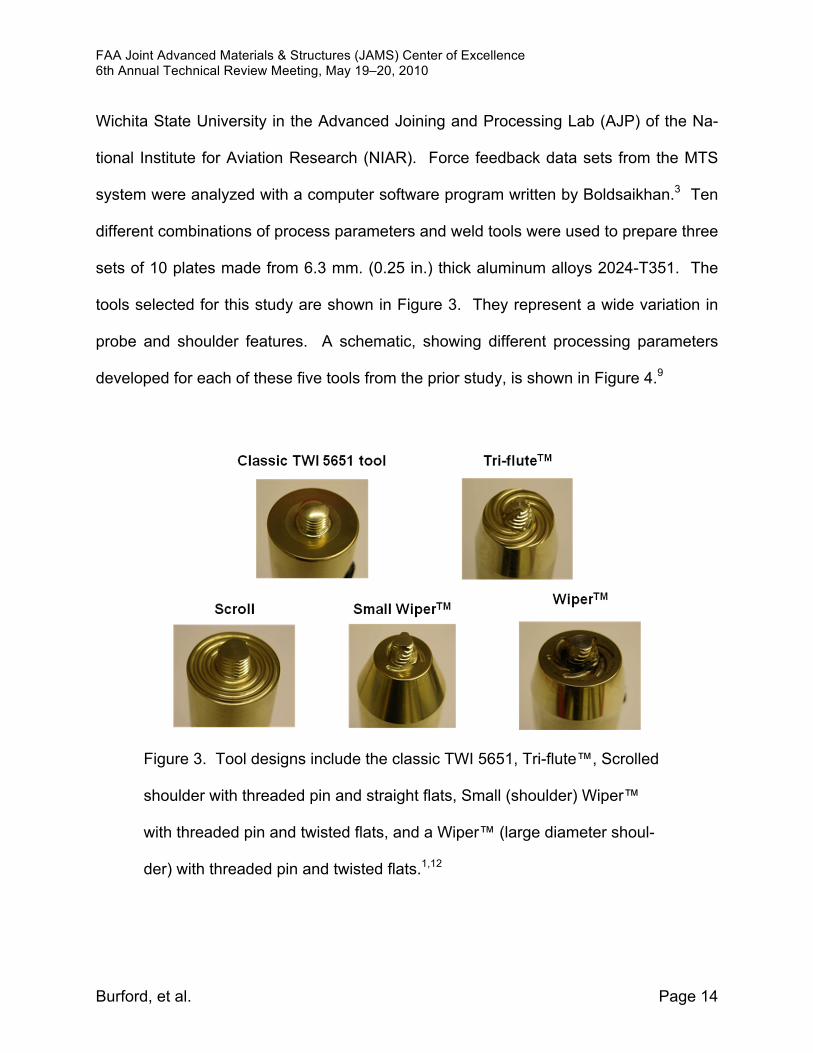
sets of 10 plates made from 6.3 mm. (0.25 in.) thick aluminum alloys 2024-T351. The
tools selected for this study are shown in Figure 3. They represent a wide variation in
probe and shoulder features. A schematic, showing different processing parameters
developed for each of these five tools from the prior study, is shown in Figure 4.9
Figure 3. Tool designs include the classic TWI 5651, Tri-flute™, Scrolled
shoulder with threaded pin and straight flats, Small (shoulder) Wiper™
with threaded pin and twisted flats, and a Wiper™ (large diameter shoul-
der) with threaded pin and twisted flats.1,12
FAA Joint Advanced Materials & Structures (JAMS) Center of Excellence 6th Annual Technical Review Meeting, May 19–20, 2010
Burford, et al. Page 15
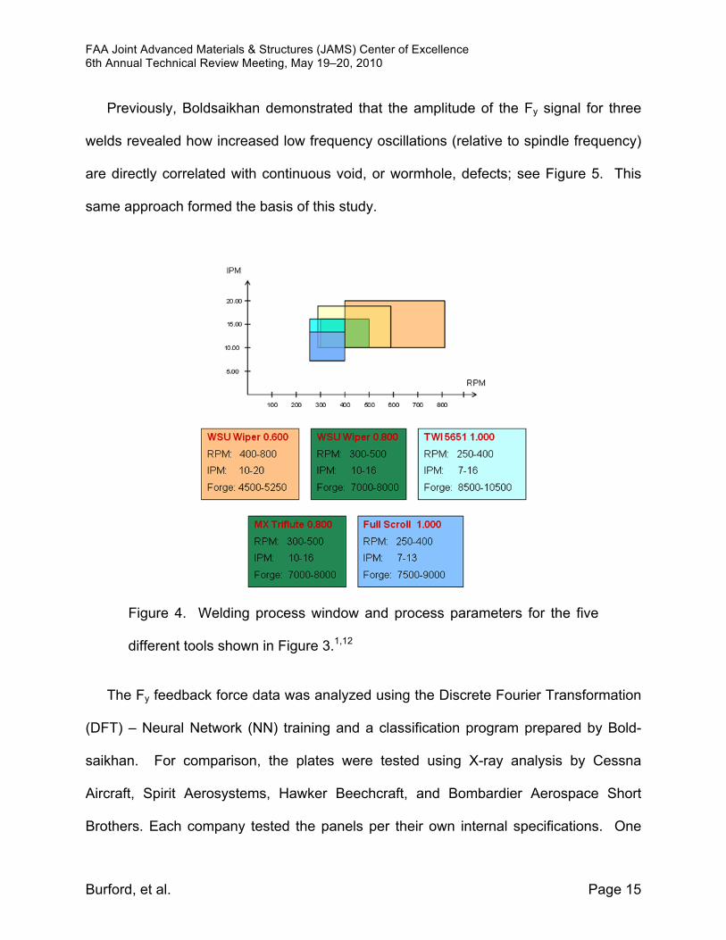
Previously, Boldsaikhan demonstrated that the amplitude of the Fy signal for three
welds revealed how increased low frequency oscillations (relative to spindle frequency)
are directly correlated with continuous void, or wormhole, defects; see Figure 5. This
same approach formed the basis of this study.
Figure 4. Welding process window and process parameters for the five
different tools shown in Figure 3.1,12
The Fy feedback force data was analyzed using the Discrete Fourier Transformation
(DFT) – Neural Network (NN) training and a classification program prepared by Bold-
saikhan. For comparison, the plates were tested using X-ray analysis by Cessna
Aircraft, Spirit Aerosystems, Hawker Beechcraft, and Bombardier Aerospace Short
Brothers. Each company tested the panels per their own internal specifications. One
FAA Joint Advanced Materials & Structures (JAMS) Center of Excellence 6th Annual Technical Review Meeting, May 19–20, 2010
Burford, et al. Page 16
company also provided ultrasonic phased array (UPA) results for 28 of the plates.
“Probability of detection” (POD) curves were then constructed based on the inspection
report submitted by each company. The results were compared against metallographic
inspection and mechanical tensile test results performed in the AJP lab.
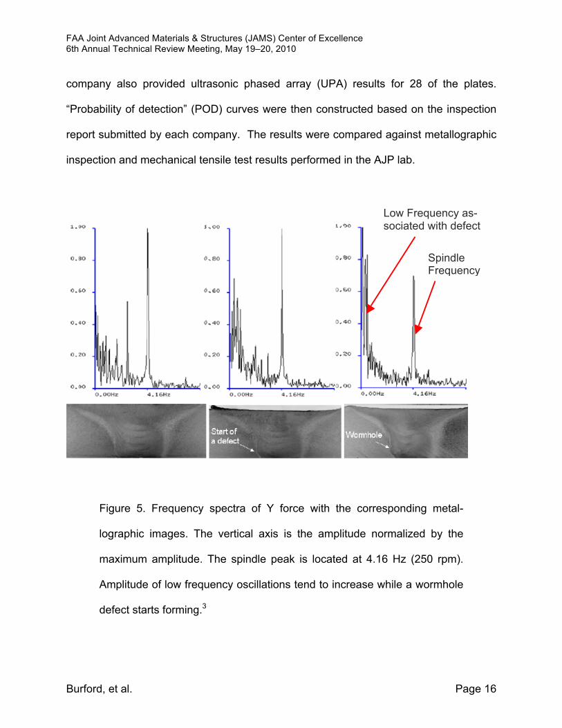
Figure 5. Frequency spectra of Y force with the corresponding metal-
lographic images. The vertical axis is the amplitude normalized by the
maximum amplitude. The spindle peak is located at 4.16 Hz (250 rpm).
Amplitude of low frequency oscillations tend to increase while a wormhole
defect starts forming.3
Low Frequency as-sociated with defect
Spindle Frequency
FAA Joint Advanced Materials & Structures (JAMS) Center of Excellence 6th Annual Technical Review Meeting, May 19–20, 2010
Burford, et al. Page 17
All indications were marked on the plates based on the inspection reports of the
round robin participants. Metallographic inspection and mechanical test coupons were
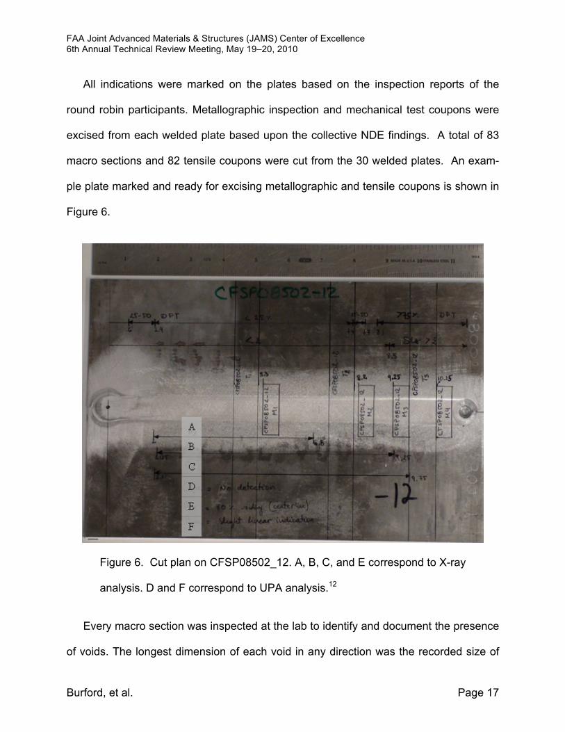
excised from each welded plate based upon the collective NDE findings. A total of 83
macro sections and 82 tensile coupons were cut from the 30 welded plates. An exam-
ple plate marked and ready for excising metallographic and tensile coupons is shown in
Figure 6.
Figure 6. Cut plan on CFSP08502_12. A, B, C, and E correspond to X-ray
analysis. D and F correspond to UPA analysis.12
Every macro section was inspected at the lab to identify and document the presence
of voids. The longest dimension of each void in any direction was the recorded size of
FAA Joint Advanced Materials & Structures (JAMS) Center of Excellence 6th Annual Technical Review Meeting, May 19–20, 2010
Burford, et al. Page 18
the void. In the situation of multiple voids in the same macro section, the dimension of
the largest void was used. Each void associated with a cluster of voids was recorded
separately. Although a cluster of voids may affect the overall tensile properties, the pri-
mary concern in this study was the ability to detect the size each void.
The neural network (NN) algorithm provided by Boldsaikhan, described else-
where,13,14 was trained using three feature vectors per each point of interest obtained
from the Fy feedback force signal. Two were used to train the NN, and the third point
was used to test the classification computed by the NN based on the other two. It was
possible to train the NN with 100% of the feature vectors, and the NN was able to cor-
rectly classify 92.7% of the samples. Only 3 samples of a total of 28 were false
classifications and only 3 samples with voids were not detected.
Discussion of Results
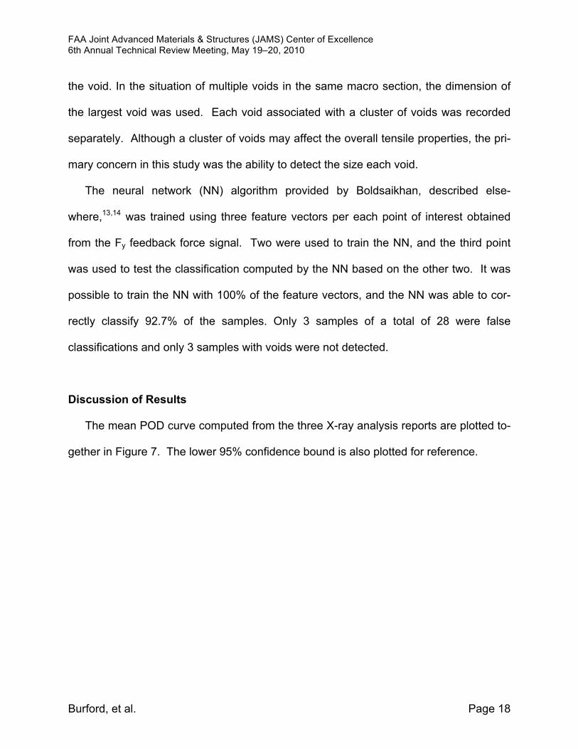
The mean POD curve computed from the three X-ray analysis reports are plotted to-
gether in Figure 7. The lower 95% confidence bound is also plotted for reference.
FAA Joint Advanced Materials & Structures (JAMS) Center of Excellence 6th Annual Technical Review Meeting, May 19–20, 2010
Burford, et al. Page 19
Figure 7: Mean POD curve versus void size computed from the three re-
ported X-ray analyses.12
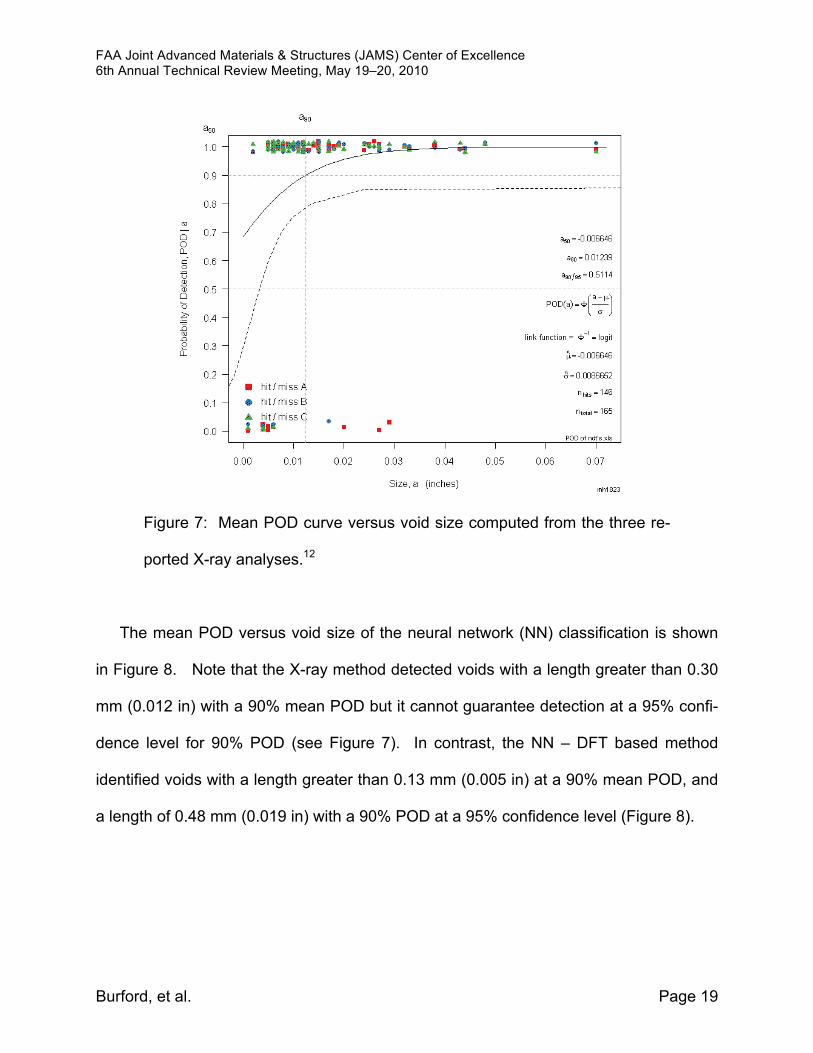
The mean POD versus void size of the neural network (NN) classification is shown
in Figure 8. Note that the X-ray method detected voids with a length greater than 0.30
mm (0.012 in) with a 90% mean POD but it cannot guarantee detection at a 95% confi-
dence level for 90% POD (see Figure 7). In contrast, the NN – DFT based method
identified voids with a length greater than 0.13 mm (0.005 in) at a 90% mean POD, and
a length of 0.48 mm (0.019 in) with a 90% POD at a 95% confidence level (Figure 8).
FAA Joint Advanced Materials & Structures (JAMS) Center of Excellence 6th Annual Technical Review Meeting, May 19–20, 2010
Burford, et al. Page 20
Figure 8: Mean POD versus void size for the NN analysis results.12
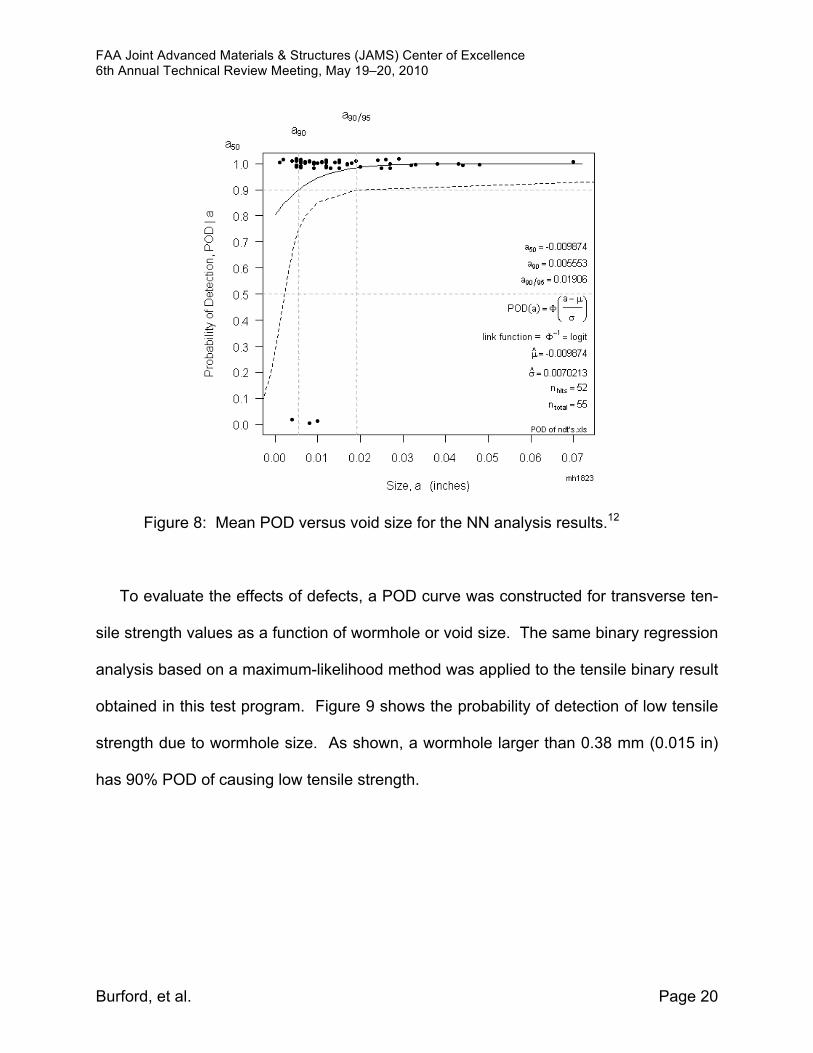
To evaluate the effects of defects, a POD curve was constructed for transverse ten-
sile strength values as a function of wormhole or void size. The same binary regression
analysis based on a maximum-likelihood method was applied to the tensile binary result
obtained in this test program. Figure 9 shows the probability of detection of low tensile
strength due to wormhole size. As shown, a wormhole larger than 0.38 mm (0.015 in)
has 90% POD of causing low tensile strength.
FAA Joint Advanced Materials & Structures (JAMS) Center of Excellence 6th Annual Technical Review Meeting, May 19–20, 2010
Burford, et al. Page 21
Figure 9: Effect of Defect - Mean POD versus void size for the Tensile
Test analysis results.12
To summarize, the trained neural network (NN) system evaluated in this study was
found to provide better detection capability than either X-ray, a non-destructive method,
or tensile testing, a destructive test method.
Conclusions
The ability to both monitor and correlate Fy force feedback signals to the occurrence
of defect formation provides a major opportunity to actively and adaptively control FSW
operations in production. This unique process monitoring tool will form the basis of a

FAA Joint Advanced Materials & Structures (JAMS) Center of Excellence 6th Annual Technical Review Meeting, May 19–20, 2010
Burford, et al. Page 22
powerful e-NDE technique that will greatly reduce inspection costs, both in terms of time
and resources, as well as in terms of accuracy and quality. Because of its evaluation
capability, process monitoring of Fy (transverse) feedback forces provides a viable al-
ternative or complement to conventional NDE techniques. As an e-NDE near real-time
inspection technique, process monitoring for force feed back signals adds a second
layer of “greenness” to an already extremely green process by reducing and potentially
eliminating the need for secondary inspection operations like penetrant, X-ray, and ul-
trasonic inspections. It can also conceivably be developed to monitor tool wear,
optimize design and performance of FSW tools, and compete different tooling design
concepts, etc. In terms of establishing standards and specifications for friction stir tech-
nologies, the e-NDE technique featured in this paper will greatly facilitate the
establishment of performance based specifications for FSW that will ultimately become
the basis of developing design data for FSW joints in multiple structures made from mul-
tiple alloys and product forms.
FAA Joint Advanced Materials & Structures (JAMS) Center of Excellence 6th Annual Technical Review Meeting, May 19–20, 2010
Burford, et al. Page 23
Future Work
The basic principles outlined for force feedback process monitoring have potential
applications in other processes and materials systems. For example, drilling holes in
composites for mechanical fasteners introduces a point load on these highly laminar
materials. If the drilling process is not performed properly, cracks and thermal stresses
may be introduced into the material during the drilling process, significantly degrading
the mechanical performance of the joint.15 Monitoring and controlling the thrust force
(axial feedback force) when drilling is crucial to maintaining quality holes. The axial
force is a function of the feed rate and drill performance and, therefore, can be used as
an indicator of the quality and efficiency of the process. So far, no significant studies
have been reported on controlling the drilling process for composites using the feedback
signals. Hence, one of the important objectives of potential future work would be to ad-
vance the state of drilling practice by introducing an intelligent process monitoring
analysis technique.
FAA Joint Advanced Materials & Structures (JAMS) Center of Excellence 6th Annual Technical Review Meeting, May 19–20, 2010
Burford, et al. Page 24
Acknowledgements
This research work was completed with the support of the staff and students of the
Advanced Joining & Processing (AJ&P) Lab of the National Institute for Aviation Re-
search (NIAR) located at Wichita State University, 1845 Fairmount, Wichita, Kansas. It
was funded under the FAA project, Evaluation of Friction Stir Weld Process and Proper-
ties for Aircraft Application, grant 04-C-AM-WISU-A28, through a membership in the
Center for Friction Stir Processing (CFSP), an NSF I/UCRC. Materials utilized in this-
work were graciously provided by Cessna. The Welding Institute provided several of the
tool designs evaluated in this study. The NIAR Research Machine Shop fabricated all
of the friction stir welding tools. The X-ray analyses were conducted by Cessna Aircraft,
Spirit Aerosystems, Hawker Beechcraft, and Bombardier Aerospace Short Brothers.
The UPA analyses were conducted by Cessna Aircraft and Bombardier Aerospace
Short Brothers.
FAA Joint Advanced Materials & Structures (JAMS) Center of Excellence 6th Annual Technical Review Meeting, May 19–20, 2010
Burford, et al. Page 25
References
1 D. Burford, C. Widener, B. Tweedy, “Path Independence of Friction Stir Welding
and Friction Stir Spot Welding Developed as an “In Situ” Integral Fastener System,”
8th International Conference on Trends in Welding Research Conference, Session
5 - Friction Stir Welding - Processing II, Callaway Gardens Resort, Pine Mountain,
Georgia USA,1-6 June 2008.
2 Y. Zhang and N. Sims, “Milling workpiece chatter avoidance using piezoelectric ac-
tive damping: a feasibility study,” Smart Mater. Struct. 14 (2005) N65–N70.
3 E. Boldsaikhan, “The use of feedback forces for nondestructive evaluation of friction
stir welding,” Doctorial Dissertation, Materials Science, South Dakota School of
Mines and Technology, 2008.
4 T. Jene, G. Dobmann, G. Wagner, and D. Eifler, “MonStir – Monitoring of the Fric-
tion Stir Welding Process,” 7th International Symposium on Friction Stir Welding,
Awaji Yumebutai Conference Centre, Awaji Island, Japan, 20-22 May 2008.
5 W. Arbegast, “Modeling Friction Stir Joining as a Metalworking Process” Hot De-
formation of Aluminum Alloys III, edited by Jin Z. TMS (The Minerals, Metals, and
Materials Society), 2003.
6 N. Balasubramanian, B. Gattu, and R. Mishra, “Process forces during friction stir
welding of aluminium alloys,” Science and Technology of Welding and Joining,
2009, Vol. 14, No. 2, 141-145.
FAA Joint Advanced Materials & Structures (JAMS) Center of Excellence 6th Annual Technical Review Meeting, May 19–20, 2010
Burford, et al. Page 26
7 D. Burford, “Friction Stir Welding of Airframe Structure: From One Delivery System
to Another,” SAE 2003 Transactions, Journal of Aerospace, Section. 1, Vol. 112,
295-300.
8 http://files.aws.org/pr/122109.pdf; Last accessed May 10, 2010.
9 D. Burford, C. Widener, “Evaluation of Friction Stir Welding Process and Properties
for Aerospace Application: Standards and Specifications Development,” Federal
Aviation Administration Joint Advanced Materials and Structures (JAMS), CoE
Technical Review Meeting, hosted by CECAM at Wichita State University, 21-22
July 2009.
10 C.Widener, B. Tweedy, & D. Burford, “Path Independence of Allowables Based
Friction Stir Butt Welds,” 7th AIAA Aviation Technology, Integration and Operations
Conference (ATIO) Belfast, Northern Ireland, 18-20 September 2007, Paper 40-
ATIO-40 / AIAA-2007-7864.
11 C. Widener, B. Tweedy, & D. Burford, “An Investigation of the Effects of Tool De-
sign and Welding Parameters on Fatigue Life In Friction Stir Welded 2024-T3,”
Paper 57, 7th International Friction Stir Welding Symposium, Awaji Yumebutai Con-
ference Centre, Awaji Island, Japan, 20-22 May 2008.
12 P. Gimenez Britos, “Probability of Detection in Friction Stir Welding Using Nonde-
structive Evaluation Techniques,” Master’s Thesis, Industrial Engineering, Wichita
State University, May 2010.
FAA Joint Advanced Materials & Structures (JAMS) Center of Excellence 6th Annual Technical Review Meeting, May 19–20, 2010
Burford, et al. Page 27
13 P. Gimenez-Britos, C. Widener, E. Boldsaikhan, D. Burford, “Probability of Detec-
tion Analysis of NDT Methods for Friction Stir Welded Panels,” 8th International
Friction Stir Welding Symposium, MARITIM Seehotel, Timmendorfen Strand, Ger-
many, 18-20 May 2010.
14 E. Boldsaikhan, A. Logar, and E. Corwin, “Real-Time Monitoring in Friction Stir
Welding: The Use of Feedback Forces for Nondestructive Evaluation of Friction Stir
Welding”, Lambert Academic Publishing, 2010.
15 K. Kokkonen and N. Potdar, Mechanical drilling of composite materials, Handbook
of Composites, second edition. Edited by S.T. Peters, Process Research, Mountain
View, California, USA, Published in 1998 by Chapman and Hall, London


![Maximizing Strength of Friction Stir Spot Welded ...d.researchbib.com/f/8nnKOup2bho3WaY0yWFx1SY1... · recent times to weld aluminum alloys [5], [6], [7]. Friction stir spot welding](https://img.pdfslide.net/doc/110x75/5f099a157e708231d4279dfb/maximizing-strength-of-friction-stir-spot-welded-d-recent-times-to-weld-aluminum.jpg)


![Friction Stir Welding of Shipbuilding Steel with Primer · McPerson et al. [8] compared fatigue behaviour of submerged arc and friction stir weld in DH36 concluding on am improved](https://img.pdfslide.net/doc/110x75/5eb597e5216c0a5a983bbe28/friction-stir-welding-of-shipbuilding-steel-with-mcperson-et-al-8-compared-fatigue.jpg)