Embed Size (px)
Citation preview

dtiEVALUATION OF HYDROGEN DEMONSTRATION SYSTEMS
(TASK 18 OF IEA IMPLEMENTING AGREEMENT ON HYDROGEN)
CONTRACT NUMBER: F/04/00279/00/00
URN NUMBER: 05/905

The DTI drives our ambition of ‘prosperity for all’ by working to create the best environment for business success in the UK.We help people and companies become more productive by promoting enterprise, innovation and creativity.
We champion UK business at home and abroad. We invest heavily in world-class science and technology.We protect the rights of working people and consumers. And we stand up for fair and open markets in the UK, Europe and the world.

EVALUATION OF HYDROGEN DEMONSTRATION SYSTEMS (TASK 18 OF IEA IMPLEMENTING AGREEMENT
ON HYDROGEN)
REPORT NUMBER F/04/00279/00/REP
Contractor
EA Technology Limited
Prepared by: J N Baker and S Carter
The work described in this report was carried out under contract as part of the DTI Technology Programme: New and Renewable Energy. The views and judgements expressed in this report are those of the contractor and do not necessarily reflect those of the DTI.
First published 2005 © Crown Copyright 2005

EXECUTIVE SUMMARY
Background
The International Energy Agency (IEA) was established in the mid-1970s, in response to increasing concerns in relation to the developed Western world’s dependency on petroleum fuels. Its membership comprises some 26 countries, drawn principally from the Organisation for Economic Co-operation and Development (OECD) member countries.
The IEA’s programme of strategic R&D activities comprises various Implementing Agreements, including the current Hydrogen Implementing Agreement. Various projects, or Tasks, are performed within such individual Implementing Agreements, with sub-sets of the various member countries electing to participate in these, under the overall co-ordination of an international Operating Agent.
The Hydrogen Implementing Agreement has initiated a new Task, termed Task 18, Demonstration Systems. Task 18 is led by a US DoE appointed Operating Agent. Twelve countries/entities are participating in Task 18, namely Canada, Denmark, the European Union, France, Iceland, Italy, Japan, Norway, Spain, Sweden, the UK and the US.
Objectives
The overall aim of Task 18 is to provide its participants with information and data about the integration of hydrogen into society around the world. The work is disaggregated into two principal sub-tasks, namely:-
Subtask A: Database Development
Subtask A collates information on an international basis in relation to hydrogen systems technology, policy issues, initiatives and regulatory matters. Specific activities and deliverables include:-
• assessment and characterisation of hydrogen systems investments, commitments, initiatives and activities, on an international basis
• development of a database of hydrogen systems component manufacturers, developers, infra-structure and resources
• collation of hydrogen systems commercialisation roadmaps, for the various participating countries
• review of previous hydrogen systems analyses, including well to wheels studies
Subtask B: Demonstration Projects
The objective of the Subtask B activities is to identify suitable candidate demonstration projects from across the participating countries and, via consensus between the Task Participants, to agree on those projects which should be the subject of detailed review and
(i)

analysis. Projects falling within this latter category will then be carried forward for detailed modelling and analysis studies. Specific activities and deliverables will include:-
• establishment of an agreed, consistent information and data assessment format
• submission of individual national case studies
• performance of associated modelling and assessment work
The UK is presently participating in subtask B only. EA Technology discharged the role of UK Participating Agent for the first year of Task 18, on behalf of the Department of Trade and Industry (DTI). As such, it was responsible for the collation of information and data in relation to specific UK hydrogen demonstration projects/case studies.
Approach
The work was conducted by a structured combination of desk research, literature review, telephone dialogue and direct meetings with a range of hydrogen project related developers and operators in the UK. The work was conducted as an integral part of the overall Task 18 work programme, with a series of twice yearly international Experts’ Meetings serving as the principal information exchange mechanism for the Task. EA Technology therefore participated in the March and September 2004 Experts’ Meetings, as part of its Participating Agent role.
The principal focus of the first year’s work related to the identification of candidate UK hydrogen demonstration systems, suitable for analysis and review as part of the overall Task 18 work programme. The emphasis of this first year’s work therefore reflected that of the Task itself, i.e. in relation to integrated hydrogen systems per se, with a further consideration relating to the likely availability of information and data during the three year currency of the Task.
One further consideration that applies in the UK context is not only to identify suitable projects that satisfy the criteria above, but that are also amenable to the exchange of project related data, within the context of the IEA framework. EA Technology’s position here differs somewhat from a number of the other national participants, who effectively bring their own demonstration projects to the subtask.
Results
The work programme succeeded in identifying a range of hydrogen related demonstration projects in the UK, ranging from technically simple hydrogen fuelled fuel cell installations, vehicle re-fuelling stations, through to integrated renewable energy/hydrogen systems. The status of these various demonstration projects ranges from projected or proposed, through those under construction, to commissioned and operational facilities. The principal hydrogen related demonstration activities identified and described in the report are:-
• the CUTE re-fuelling station at Hornchurch
• the HARI project, Leics.
(ii)
• the Hunterston Hydrogen Project
• the PURE Project, Unst
• the Tees Valley Hydrogen Project,
complemented by associated developments in relation to the Fuel Cell House, the Hydrogen Office, INEOS Chlor, the London Hydrogen Partnership and the Wales Hydrogen Project.
Six of the above project developments are currently operational, albeit with only the HARI Project satisfying the requirement for “integrated hydrogen systems”. However, other project developments identified and which are likely to be realised and to provide data within the three year currency of Task are the Hornchurch CUTE re-fuelling station and the PURE project. These latter two projects are both scheduled for completion and commissioning, early 2005.
A far higher degree of uncertainty is attached to the timing of the various other developments, particularly in relation to the possibility of their producing operational data, consistent with the timescales of Task 18.
The three candidate UK demonstration projects identified for inclusion in the overall Task 18 workplan are therefore the HARI Project, the PURE Project and the Hornchurch CUTE refuelling station. Agreement has been reached with the key stakeholders in these developments, in relation to their participation in the Subtask B demonstration project analysis framework.
(iii)

Implications
The work has identified a range of hydrogen related demonstration activities in the UK, either already operational, under construction or planned. Compressed gaseous hydrogen fuelled fuel cell installations represent the majority of implementations to date, but with the HARI Project representing a highly significant demonstration of an integrated renewable energy/hydrogen system. Further significant developments, which are anticipated to be realised within the next six months, are the Hornchurch CUTE re-fuelling station and the PURE Project. Each of the latter two projects is technically significant and of considerable interest to Task 18.
It is therefore recommended that the HARI, PURE and Hornchurch projects should form the UK contribution for analysis and review within Task 18. The UK should also take every opportunity to learn from overseas best practice, as it further develops its own hydrogen related programme activities.
(iv)

CONTENTS
Page
1. INTRODUCTION 1
2. AIMS AND OBJECTIVES 3
3. UK HYDROGEN PROJECT DEMONSTRATION ACTIVITIES 4
3.1 The CUTE Re-fuelling Station at Hornchurch, Essex 73.1.1 Development of Hornchurch Re-fuelling Station 73.1.2 The Hornchurch Hydrogen Re-fuelling Station 8
3.2 The HARI Project (Hydrogen and Renewables Integration) 11
3.3 The Hunterston Hydrogen Project and AssociatedDevelopments 163.3.1 The Hunterston Hydrogen Project 163.3.2 Associated Scheme Proposals 17
3.4 The PURE Project (Promoting Unst Renewable Energy) 17
3.5 Tees Valley Hydrogen Project 213.5.1 The Middlesbrough Transporter Bridge
Variable Message Sign 213.5.2 Tees Lighthouse 213.5.3 Public Demonstrations 223.5.4 The Middlehaven Project 223.5.5 Fleet and Fuelling Project 223.5.6 Hydrogen Greening 223.5.7 Wind Hydrogen 22
3.6 Other UK Hydrogen Scheme Developmental Activities 233.6.1 The CymruH2Wales Project
(The Wales Hydrogen Project) 233.6.2 The Fuel Cell House 233.6.3 The Hydrogen Office 233.6.4 INEOS Chlor Hydrogen Fuelled Fuel Cell Demonstration, Runcorn233.6.5 The London Hydrogen Partnership 23
4. OVERSEAS DEMONSTRATION PROJECTS 24
5. SELECTION OF CANDIDATE UK PROJECTS FOR MORE DETAILEDANALYSIS AND REVIEW UNDER TASK 18 25
(v)

6. ANALYSIS FRAMEWORK 27
7. CONCLUSIONS 28
8. RECOMMENDATIONS FOR FUTURE WORK 29
REFERENCES 30
ACKNOWLEDGEMENTS 31
W

GLOSSARY
ACAFCAIST
B-o-PCNGCRESTCUTEDCDoEDTIECTOSESTExCoFIRSTHARIHHLLEDLH2
ODPMOECDPAFCPEMPURERAFR&DROCTfLWHL
Suffixesegth
Alternating current Alkaline fuel cellNational Institute of Advanced Industrial Science and Technology (Japan)Balance-of-plantCompressed natural gasCentre for Renewable Energy SystemsClean Urban Transport for EuropeDirect currentDepartment of Energy (USA)Department of Trade & Industry Ecological city transport system Energy Saving Trust Executive CommitteeFuel cell innovative system for remote telecommunicationsHydrogen and renewables integrationHunterston Hydrogen LimitedLight emitting diodeLiquid hydrogenOffice of the Deputy Prime MinisterOrganisation for Economic Co-operation and DevelopmentPhosphoric acid fuel cellProton exchange membranePromoting Unst Renewable EnergyRoyal Air ForceResearch & DevelopmentRenewables Obligation CertificateTransport for LondonWind Hydrogen Limited
electricalgaugethermal
(vii)

1. INTRODUCTION
The International Energy Agency (IEA) was established in 1974, in response to increasing concerns in relation to the developed Western world’s dependency on petroleum fuels. Its membership comprises some 26 countries, drawn principally from the Organisation for Economic Co-operation and Development (OECD) member countries.
The IEA’s programme of strategic R&D activities addresses various areas of energy technology via a framework of Implementing Agreements, which essentially establish the basis for collaborative Research and Development (R&D) and information exchange, between particular sub-sets of the IEA member countries. Various projects, or Tasks (Annexes), are performed within such individual Implementing Agreements, with sub-sets of the various member countries electing to participate in these, under the overall co-ordination of an international Operating Agent. A high level Executive Committee (ExCo) is responsible for the overall co-ordination of activities within the Implementing Agreement.
The IEA’s Hydrogen Implementing1 was established in the early 1980s and presently has fifteen members. Task 18 of the IEA’s Hydrogen Implementing Agreement, which addresses demonstration systems, was initiated January 2004, following a programme of dialogue between various interested parties, from late 2002 on. The Task is presently planned to run for three years, through to December 2006. The Task 18 Operating Agent is Longitude 122 West, appointed by the US Department of Energy (DoE); this reflects the US leadership of Task 18. Task 18 presently has twelve participating countries/entities2’ each represented by their own Participating Agent. EA Technology discharges the UK Participating Agency role, on behalf of the Department of Trade and Industry (DTI). Figure 1.1 shows the organisational structure of Task 18, within the overall framework of the Hydrogen Implementing Agreement.
1 International Energy Agency. Implementing Agreement on Hydrogen2 The members of Task 18 comprise Canada, Denmark, the European Union, France, Iceland, Italy, Japan, Norway, Spain, Sweden, UK and USA.
1

anada
Eenmark
ance
celand
Norway
pain
den
y
National Participating Agents
Figure 1.1: Organisational Structure, IEA Hydrogen Implementing Agreement,Task 18
2

2. AIMS AND OBJECTIVES
The overall aim of Task 18 is to provide its participants with information and data about the integration of hydrogen into society around the world. The work is disaggregated into two principal sub-tasks, namely:-
Subtask A: Database Development
Subtask A collates information on an international basis in relation to hydrogen systems technology, policy issues, initiatives and regulatory matters. Specific activities and deliverables include:-
• assessment and characterisation of hydrogen systems investments, commitments, initiatives and activities, on an international basis
• development of a database of hydrogen systems component manufacturers, developers, infra-structure and resources
• collation of hydrogen systems commercialisation roadmaps, for the various participating countries
• review of previous hydrogen systems analyses, including well to wheels studies
Subtask B: Demonstration Projects
The objective of the Subtask B activities is to identify suitable candidate demonstration projects from across the participating countries and, via consensus between the Task Participants, to agree on those projects which should be the subject of detailed review and analysis. Projects falling within this latter category will then be carried forward for detailed modelling and analysis studies. Specific activities and deliverables include:-
• establishment of an agreed, consistent information and data assessment format
• submission of individual national case studies
• performance of associated modelling and assessment work
The UK is presently participating in Subtask B only. EA Technology discharges the role of UK Participating Agent on behalf of the DTI and is responsible for the collation of information and data in relation to specific UK hydrogen demonstration projects.
3
3. UK HYDROGEN PROJECT DEMONSTRATION ACTIVITIES
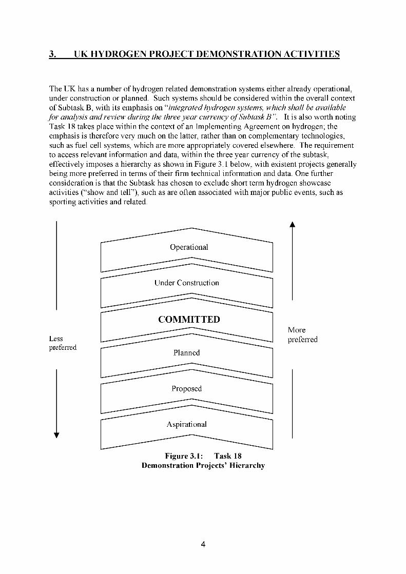
The UK has a number of hydrogen related demonstration systems either already operational, under construction or planned. Such systems should be considered within the overall context of Subtask B, with its emphasis on “integrated hydrogen systems, which shall be available for analysis and review during the three year currency of Subtask B”. It is also worth noting Task 18 takes place within the context of an Implementing Agreement on hydrogen; the emphasis is therefore very much on the latter, rather than on complementary technologies, such as fuel cell systems, which are more appropriately covered elsewhere. The requirement to access relevant information and data, within the three year currency of the subtask, effectively imposes a hierarchy as shown in Figure 3.1 below, with existent projects generally being more preferred in terms of their firm technical information and data. One further consideration is that the Subtask has chosen to exclude short term hydrogen showcase activities (“show and tell”), such as are often associated with major public events, such as sporting activities and related.
Operational
Under Construction
COMMITTED
Lesspreferred
Planned
Proposed
Aspirational
Figure 3.1: Task 18 Demonstration Projects’ Hierarchy
A
Morepreferred
4
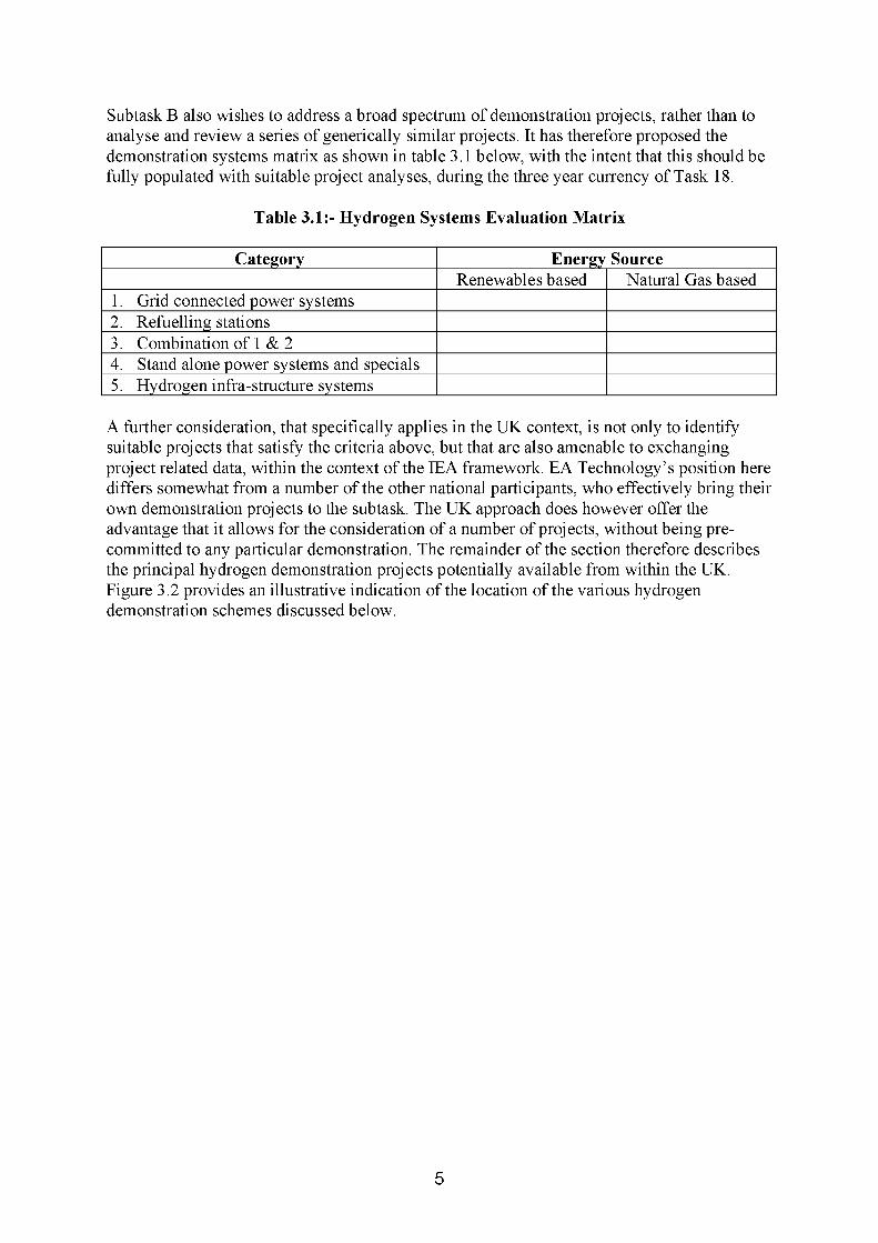
Subtask B also wishes to address a broad spectrum of demonstration projects, rather than to analyse and review a series of generically similar projects. It has therefore proposed the demonstration systems matrix as shown in table 3.1 below, with the intent that this should be fully populated with suitable project analyses, during the three year currency of Task 18.
Table 3.1:- Hydrogen Systems Evaluation Matrix
Category Energy SourceRenewables based Natural Gas based
1. Grid connected power systems2. Refuelling stations3. Combination of 1 & 24. Stand alone power systems and specials5. Hydrogen infra-structure systems
A further consideration, that specifically applies in the UK context, is not only to identify suitable projects that satisfy the criteria above, but that are also amenable to exchanging project related data, within the context of the IEA framework. EA Technology’s position here differs somewhat from a number of the other national participants, who effectively bring their own demonstration projects to the subtask. The UK approach does however offer the advantage that it allows for the consideration of a number of projects, without being precommitted to any particular demonstration. The remainder of the section therefore describes the principal hydrogen demonstration projects potentially available from within the UK. Figure 3.2 provides an illustrative indication of the location of the various hydrogen demonstration schemes discussed below.
5

KEY
Constructed
UnderConstruction
Planned
Proposed
PURE, Unst
Shetland Wind Hydrogen
Hydrogen Office
Hunterston 0 Hydrogen
Project
Tees Valley Hydrogen Project
jINEOS Chlor
■HARI, Leics■Hydrogen House
0 Wales Hydrogen Project
Hornchurch CUTE refuelling station
0 London Hydrogen Project
© Crown Copyright 2005. Image reproduced with permission of Ordnance Survey and Ordnance Survey of Northern Ireland. AEAT Environment, licence no 100023800.
Figure 3.2: Location of Principal Hydrogen Related Demonstrations
6

3.1 The CUTE Re-fuelling Station at Hornchurch, Essex
The demonstration of three Mercedes-Benz Citaro hydrogen fuelled fuel cell buses in London forms an integral part of the pan-European demonstration of 27 such vehicles in nine participating cities, performed under the auspices of the European Commission’s CUTE project (Clean Urban Transport for Europe). The London based demonstration of the vehicles is co-ordinated by Transport for London (TfL), in partnership with Daimler Chrysler, BP, First and the Energy Saving Trust (EST). The vehicles were delivered from December 2003 on and commenced a two year public demonstration programme, in January 2004 (1).
The vehicles run on compressed gaseous hydrogen, with on-board storage being in the form of six roof mounted hydrogen cylinders. BP, as infra-structure partner, is responsible for the provision of the re-fuelling facilities and is similarly participating in another two of the CUTE cities3, where it is demonstrating a range of different hydrogen technologies, in each location. BOC has been engaged on a “capable supplier” basis by BP, for the provision of expert advice in relation to systems engineering, integration and health and safety aspects in relation to the various CUTE re-fuelling stations.
3.1.1 Development of Hornchurch Re-fuelling Station
The re-fuelling station for the London based CUTE buses was planned from the project outset to be located at BP’s filling station at Hornchurch, in Essex. This filling station was opened February 2002 as an exemplar of environmental best practice and incorporates wind turbines, solar photo-voltaics and a closed water system. The site is located in a metropolitan green belt area. For the purposes of the CUTE project, the site would be further developed to incorporate underground vaulted liquid hydrogen storage (LH2), associated Balance-of-Plant (BoP) and fuelling dispensers. The site was to be unique in the CUTE project, in that the hydrogen fuelling station was to be on a publicly accessible forecourt, in contrast to the other CUTE re-fuelling stations, which are located on restricted access premises.
The original plans to develop the hydrogen fuelling facility at Hornchurch, such as to be available coincidental with the introduction of the buses into service suffered a severe setback in July 2003. Havering Council, as the relevant planning authority rejected BP’s planning application, on the grounds that the proposed development was “inappropriate for a metropolitan green belt area” (2). As an interim measure, a re-fuelling facility was arranged at BOC’s existing Hackney depot, in East London, with the vehicles re-fuelled from compressed gaseous hydrogen storage cylinders. This allowed the vehicles to be introduced into public service operation, January 2004, on Route 25, running between Oxford Circus and Ilford.
Coincidentally, BP chose to appeal against Havering Council’s decision, with the proposed development then becoming the subject of a Public Inquiry, May 2004. The recommendations from this Inquiry were passed to the Office of the Deputy Prime Minister (ODPM) in June, with the Council’s decision being reversed and planning permission granted, 22nd July 2004. It is not the purpose of the present report to provide a full and detailed commentary on the various planning issues and inter-actions involved. However, it
3 BP is owner/operator for the London, Porto and Barcelona fuelling stations. BP is also a minor partner in the Hamburg and Stuttgart projects.
7
is worth noting that the whole process is regarded as an extremely valuable learning experience by BP and, in particular, with respect to the interactions between National Government, Local Government, the community stakeholders and BP, as a major multinational (3). BP and BOC were therefore able to re-assess the practicability of developing the Hornchurch facility, noting, in particular construction lead times and the likely operational duration of the facility, prior to the cessation of the CUTE demonstration activities, December 20054 The Hornchurch hydrogen re-fuelling facility is presently planned to be dismantled and removed at the end of the CUTE project.
BP re-affirmed its commitment to the development late summer 2004, with on-site construction commencing November 2004. A twelve week construction period is planned, with the re-fuelling station to be commissioned and declared operational, February 2005.
3.1.2 The Hornchurch Hydrogen Re-fuelling Station
As was noted above, the Hornchurch re-fuelling station will incorporate underground vaulted hydrogen storage, within the curtilage of the existing site.
Figure 3.3 shows a diagrammatic representation of the equipment layout.
4 The various CUTE demonstrations are scheduled to run until the late 2005/early 2006, at such time the vehicles are presently planned to be withdrawn from service.
8

VAPORISER
DISPENSER
BUFFER
STORAGE
LIQUIDUNDERGROUND STORAGE TANK
PUMP
The principal plant items comprise
• an insulated underground cryogenic hydrogen storage tank
• a cryogenic liquid hydrogen pump
• a vaporiser unit
• intermediate compressed gaseous hydrogen storage
a vehicle fuelling dispenser
Table 3.2 provides a summary of the equipment specifications and their indicative costings. These costs should be viewed in the context of a “first of a kind” installation at a location subject to local objections and, as such, are not necessarily representative of follow-on installations.
9

Table 3.2: Summary of Hornchurch Sub Systems
Sub-system Manufacturer/Supplier/ModelDesignation
Rated Performance Indicative Cost (£)
Cryogenic liquid hydrogen tank CryolorEFH53
• Vacuum insulated• 3000 kg LH2 (50,220 litres)• 12 barg working pressure• -253 °C temperature
£298,000(including £24,000 of currency
variations suffered)
Cryogenic pump ACD2-SGV
• 80 kg /hr LH• 450 barg LH
£65,000 inc spares
Vaporiser Cryoquip3T48-115-400
• 80 kg/hr LH• 115 kW electrical load
£20,000
High pressure storage FaberEN-230-675-755/B/CARB
• 15 x 50 litre composites cylinders
• Steel lined carbon fibre• Max rating 450 barg
(£600 each * 15) £9,000
Dispenser2 hose dispenser (bus/car)BP Harmony carcass
FTIBespoke
• 227 kg/hr• 450 barg max• WEH nozzle
£54,000
10

3.2 The HARI Project (Hydrogen and Renewables Integration)
The HARI project represents a demonstration of an integrated renewables / hydrogen energy storage facility at West Beacon Farm in Leicestershire, the family home of Professor Tony Marmont. The project complements the various other renewables and energy technologies installed on-site. These include wind turbines, solar photo-voltaics, low head hydro, small scale combined heat and power (CHP), battery storage and electric vehicles (4). The HARI project was conceived with the ultimate objective of achieving grid independence for West Beacon Farm, with it becoming electrically self-sufficient. As such, it represents an example of an integrated renewables/hydrogen conversion and storage installation, with the potential for hydrogen off-take, for vehicle re-fuelling purposes.
The project itself has been conducted in full collaboration with the Centre for Renewable Energy Systems Technology (CREST) at the University of Loughborough, with various aspects of its implementation forming an integral part of CREST’s research programme activities. The HARI facility is presently in its early stage of operation and is described in more detail below.
HARI incorporates the essential elements of any hydrogen energy storage and conversion system, namely electrolysis equipment, the hydrogen storage medium itself and an energy conversion medium, for the production of electricity from the stored hydrogen. In the case of HARI this comprises two fuel cell units. Figure 3.4 shows a diagrammatic representation of the system.
11

PV Wind Hydro
Battery Storage
Electrical Loads
Fuel Cell (1)
FuelCell (2)
Controller/PowerConverter
ELECTROLYSER
FIGURE 3.4: Diagrammatic Representation of HARI Installation
12

The principal plant items comprise:-
• an alkaline electrolyser unit
• a hydrogen compressor and associated drive unit
• compressed gaseous hydrogen storage, in the form of 48interconnected steel cylinders
• two proton exchange membrane (PEM) fuel cell power plant
• a bespoke system controller and power conversion system.
Various other B-o-P complements the above, including a hydrogen gas detection system and a data acquisition unit. Table 3.3 provides a summary of the equipment specifications and their indicative costings.
13

Table 3.3: Summary of HARI Sub-Systems
Sub-system Manufacturer/Supplier/ModelDesignation
Rated Performance Indicative Cost (£)
Electrolyser Stuart Energy Europe (formerly Vandenborre)
8Nm3/hour of H2, 34kW, 25bar rated
143,000
Fuel Cell (1) Intelligent Energy, CHP Unit 2kW Electrical, 2kW Thermal,24V DC
25,000
Fuel Cell (2) Plug Power GenCore, Supplied by SiGen Ltd.
5kW Electrical, 48 V DC 20,000
H2 Compressor Hydro-Pac Supplied by BOC 11Nm3/hour, 3.75kW, 8:1 compression ratio
59,000
H2 Storage Supplied by BOC 48 Cylinders, each 0.475m3,137bar Max pressure, 2856Nm3 total H2 capacity
22,000
Wind Turbines Carter Wind Turbines 2 x 25kW two bladed stall- regulated, pitch over-speed.
50,000
Solar PV BP 13kW total, mixed polycrystalline and monocrystalline
60,000
Hydro-electric Installed by Dulas 850W Cross-flow with 2m head 2.2kW Turgo with 25m head
67,000
Integration System Control Techniques and bespoke converters from Loughborough University
Various 49,000
14
Although not specifically part of the new build HARI installation, the principal renewables inputs for the system comprise:-
• 2 x 25 kW Carter wind turbines
• 13 kW of BP solar photo-voltaics
• an 850 Watt low head (2 metre) hydro system
• a 2.2 kW 25 metre head hydro system
BOC has provided engineering and technical support to the project and, in particular, has supplied the gas compressor and the 48 storage cylinders. These cylinders (or “bullets”) are BOC standard industrial hydrogen storage cylinders, rated at 137 bar (g). Total hydrogen storage capacity equates to 2,856 NM3, equivalent to some 3.8 MWh.
The two fuel cell units are each straight DC output systems, with the bespoke power conversion system handling the conversion to AC. The Intelligent Energy unit is rated at 2kWe/4kWe peak, with 4kWth of heat recovery, for CHP (Combined Heat and Power). The Plug Power unit is rated at 5 kWe and with 8 kWth of thermal output, again for CHP purposes.
As was noted above, the system was commissioned early 2004 and operating experience is progressively being developed (5,6). Overall energy conversion efficiency has been measured at around the 40% level, on a round trip basis. An early finding from the system’s operation is that the highly variable renewables loading input spectrum imposes considerable demands on standard industrial electrolysis units, of the type used in HARI, to the extent that this will significantly impact on electrolyser reliability and longevity. In the short term, the use and application of supplementary battery storage is being investigated as an intermediate “buffer store”, with the development of electrolyser technology specifically for intermittent renewables resources being part of a medium/longer term R&D objective.
Future plans in relation to the specific development of HARI include the implementation of hydride storage, the installation of additional stationary fuel cell power plant capacity and the addition of a hydrogen fuelling dispenser, for vehicular applications. The latter is likely to be used in conjunction with fuel cell supplemented battery electric cars, with the on-board fuel cells essentially used in a range extension mode. This link to the transport chain is seen as one of the eventual key objectives for the system, as the arguments in relation to round-trip efficiency then become less significant, with the further potential of utilising hydrogen production as part of an integrated load management facility for electricity production.
Complementary developments include the provision of the supplementary battery storage, as mentioned above, together with rationalisation of the Farm’s local distribution system, via the installation of a 600 volt DC bus. This is intended to facilitate the balancing of supply and demand between all the various energy technologies involved. It is also intended to modify the two wind turbines on site, such that they may operate independently of the network supply, presently used to activate and control their induction generators.
15
3.3 The Hunterston Hydrogen Project and Associated Developments
The Hunterston Hydrogen Project has been actively promoted by Hunterston Hydrogen Limited (HHL) with a view to constructing the first large scale, commercially viable wind- hydrogen scheme (7,8,9). HHL has been established as a joint venture company between Wind Hydrogen Limited and Hunterston Developments Limited, with the specific objective of pursuing the development. The Hunterston development is one of a series of such schemes proposed by Wind Hydrogen Limited, with some of these associated schemes discussed in Section 3.3.2 below. All of these developments are essentially aspirational at this stage and with funding being sought for their development.
3.3.1 The Hunterston Hydrogen Project
The Hunterston Hydrogen Project is proposed for development on the Hunterston Estate in Ayrshire, Scotland. Its commercial case is based on the electricity trading arrangements and, in particular the Renewables Obligation and the associated value of Renewables Obligation Certificates (ROCs). HHL proposes the application of hydrogen energy conversion and storage, to “buffer” circa 10% of the output from wind farms, such as firm up their output, with an increase in the value of the output from circa £15 to nearer £25 per MWh.
Key aspects of the proposed project include:-
• application of large scale industrial electrolyser plant
• large scale hydrogen storage
• energy conversion back to electricity via dedicated internal combustion engine generating sets
Table 3.4 below summarises some of the more important characteristics associated with the proposed development.
16

Table 3.4:- Hunterston Hydrogen Project Summary Parameters
Parameter Rating/V alueLocation Ladyland Moor, North Ayrshire Wind
FarmWind generation capacity 15 x 1.75 MW machines, total installed
capacity of 26.25 MWWind turbine output 92 GWh paElectrolyser capacity 5.75 x 10⁶ NM3 of hydrogen paStorage capacity 250,000 NM3 of H2, equivalent to 4 days
peak supply at 10 MW, 16:00 to 19:00 hours
Generation Plant 10 MW of gas engine generation setsScheme total capital cost £27M
3.3.2 Associated Scheme Proposals
WHL is also pursuing the basic concept of large scale wind/hydrogen load balancing schemes via two other principal proposals. The first of these relates to Shetland Wind Hydrogen Limited, which is subject to a joint development agreement with AMEC Group. The proposed development relates to the application of the wind/hydrogen concept to a 100 MW capacity wind development, in the particular context of optimising the inter-connection to the mainland.
The second significant proposal relates to the application of the concept within the context of the overall Tees Valley Hydrogen Project (see also Section 3.5 below). The Teeside Hydrogen Energy Balancing Scheme is proposed for renewables developments in the North East, but with the hydrogen storage provided via the existing underground cavern storage capacity in the region.
3.4 The PURE Project (Promoting Unst Renewable Energy)
The PURE project represents an interesting and novel application of hydrogen energy technologies, within the context of a remote community renewable energy project. Unst is the most northerly island in the British Isles, situated at the northern extremity of the Shetland Isles. The depopulation of the outlying isles has been a major concern for many decades, if not longer, with the size of their local populations directly relating to the available employment opportunities. Unst, in particular, has experienced a significant decline in population since the late 1990s, with its population declining from just over the one thousand level to the present day figure of circa seven hundred. The run-down of the local RAF base has been one significant factor here, exacerbated by the loss of other employment opportunities. The Unst Partnership has therefore been established as a not-for-profit organisation, with a view to stabilising, if not improving the local economy.
Renewable energy related opportunities have been identified as a high priority for the Shetland Isles in general, with organisations such as the Shetland Renewable Energy Forum established to promote the development of renewable energy technologies in the region. The
17

PURE project itself emanated from some original research pursued at Robert Gordons Institute of Technology, Aberdeen, by Mr Ross Gazey, who has subsequently joined the project, with the support of the Unst Partnership.
The PURE project itself is genetically similar to the HARI project (10, 11), in that it concerns the application of an integrated hydrogen energy scheme to a small scale renewables development. PURE is however a completely “new build” initiative, based on a small industrial estate, presently being developed as part of an overall package of measures to stimulate the local economy and to develop and retain expertise on the island.
Figure 3.5 shows a diagrammatic representation of the PURE project, with its key constituent elements comprising:-
• 2 x 15 kW wind turbines
• 18 kW electrolyser unit
• compressed gaseous hydrogen storage
• Plug Power PEM fuel cell
• hydrogen dispenser (for vehicle re-fuelling applications)
• a Reva electric car, converted to use a hydrogen fuel cell
• integrated control unit
Table 3.5 provides a more detailed breakdown of the individual component assemblies, their performance specifications and costings. SiGen is acting as the overall systems integrator for the project and has retained the services of the scheme’s originator, Mr Ross Gazey, for this purpose.
18

2 x 15 kW Wind Turbines
Industrial Estate Power Supply
DISPENSER
FUELCELL
Integrated Control Unit
ELECTROLYSER
Fuel Cell Electric Car
Figure 3.5: Diagrammatic Representation of PURE Installation
19

Table 3.5: Summary of PURE Sub-Systems
Sub-system Manufacturer/Supplier/ModelDesignation
Rated Performance Indicative Cost (£)
Wind turbines (2 off) Proven Engineering 2 x 15 kW £80,000Electrolyser Accagen SA, via SiGen 0.67 to 3.55 Nm3/hour at 99.999%
purity.£120,000
Hydrogen storage Accagen SA, via SiGen 16 x nominal 50 litre bottles, total capacity 44 Nm3 at 55 bar.
£15,000
PEM fuel cell Plug Power 5 kW £12,0005Systems controller SiGen Integrated power conversion and
control system, sized in relation to the inputs/outputs, as above
Reva electric car Sigen n/a
5 Unit supplied as ex-demonstrator unit by SiGen.
20

The PURE Partnership has secured a £290,000 funding package for the development, which includes contributions from the Shetland Renewable Energy Forum, Highlands & Islands, European Regional Development Fund and Shetland Enterprise. As with the HARI project, BOC is providing engineering and technical support and there is already a degree of direct dialogue and information exchange between the two projects. The present PURE construction phase is scheduled to be completed, such as to allow commissioning, April 2005.
3.5 Tees Valley Hydrogen Project
The Tees Valley Hydrogen Project has been initiated as an adjunct to the Renew Tees Valley regeneration initiative, itself established 2001/2002 to pursue a long term regeneration of the Tees Valley area, which has historically been dependent on heavy chemicals and engineering. The Tees Valley Hydrogen Project was established in 2002, following direct dialogue between Middlesbrough Council and Forum for the Future and the recognition of the potential wealth creation and employment opportunities associated with any hydrogen and fuel cell developments in the region. Such latter developments are regarded as highly complementary to the existing hydrogen related skills and infra-structure in the region. These include over 30 km of hydrogen pipelines, 600 tonnes of underground cavern hydrogen storage, combined with the production of some 70,000 tonnes of hydrogen pa, at a price level of some £40 to £50 per MWh (12,13).
The initiation of the Tees Valley Hydrogen Project was effectively marked by the coming together of a group of invited stakeholders, including BOC, Johnson Matthey and Intelligent Energy and the agreement to pursue a small series of individual projects, as described below. The first three of these represent demonstrations which have been implemented to date, with the remaining schemes either being under active development or planned for the future.
3.5.1 The Middlesbrough Transporter Bridge Variable Message Sign
The Middlesbrough Transporter Bridge is probably one of the best known landmarks in the region. The particular demonstration activity concerns the application of a fuel cell as part of an off-grid power supply, linked to a variable message sign on the approach to the Transporter Bridge. A one hundred Watt Intelligent Energy PEM fuel cell system is used for this purpose, fed from a bottled hydrogen gas feed. Although technically a very simple installation, it has nevertheless highlighted some interesting regulatory aspects, including the requirement to maintain a 5 metre separation distance from the between the sign and the hydrogen supply. It is anticipated that the demonstration will be a precursor to the commercialisation of such fuel cell powered telemetry controlled signage, for remote location (off-grid) applications.
3.5.2 Tees Lighthouse
The Tees Lighthouse demonstration again concerns the use and application of a one hundred Watt Intelligent Energy PEM fuel cell system, but applied as the power supply for the Tees Lighthouse’s 40 Watt LED (light emitting diode) beacon (noting that the use of LEDs significantly reduces the power supply requirement). The demonstration provides direct
21

operational experience of a PEM fuel cell in a saline environment. A technically simple bottled gas hydrogen feed is employed, as in the Transporter Bridge demonstration above.
3.5.3 Public Demonstrations
The first of these demonstrations concerns the application of a hydrogen fuelled 2 kW Plug Power PEM fuel cell system, operating in the visitor centre of a local crematorium. A further demonstration of a small scale CHP fuel cell is planned at a local school.
Further projects which are planned or proposed include:-
3.5.4 The Middlehaven Project
The Middlehaven Project relates to the re-development and regeneration of the Greater Middlehaven district of Middlesbrough, which will involve the reclamation and remediation of prime waterside land and its subsequent development for high quality residential, commercial, educational and leisure uses. It is intended that the Project will be implemented in phases, over the next ten years. The development of an integrated and fully optimised sustainable community energy system, incorporating a significant tranche of fuel cell CHP has been identified as an integral part of the Project’s development. An initial feasibility study has been completed in relation to the community energy system, with a 2 MWe tranche of capacity reserved for fuel cell CHP, as part of an overall 10 MWe development.
3.5.5 Fleet and Fuelling Project
The fleet and fuelling project is examining the application of various compressed natural gas (CNG), hydrogen and hydrogen/CNG blends in municipal fleets and related applications. Potential application opportunities include a hydrogen fuelled refuse vehicle and harbour launch.
3.5.6 Hydrogen Greening
The hydrogen greening project represents the potential development of a major coal gasification project, with complementary CO2 sequestration. An 800 MWe power plant is under consideration, producing 40 tonnes per hour of hydrogen for distribution into the local pipeline network and with some 4 million tonnes pa of CO2 sequestration.
3.5.7 Wind Hydrogen
This concerns the application of “hydrogen buffering” to the region’s developing renewables resource base, specifically two onshore wind farms (of 30 MW and 45 MW capacity) and an offshore development of 100 MW capacity. The project concept is being pursued in conjunction with Wind Hydrogen Limited and is planned to utilise the existing underground cavern storage capacity.
Mention should also be made of the complementary National Fuel Cell Applications Facility, which has been established to act as a national centre of expertise for fuel cell applications, testing, installation and regulatory aspects. The Facility is based at the Wilton Centre, in Redcar.
22

3.6 Other UK Hydrogen Scheme Developmental Activities
Various other hydrogen related demonstration activities are either under way, planned or proposed, with some of these being as described below (14, 15, 16, 17 & 18).
3.6.1 The CymruH2Wales Project (The Wales Hydrogen Project)
The Wales Hydrogen Project is examining the possibility of implementing one or more demonstration projects in Wales, from early 2005 on. Candidate projects include a hydrogen production station and vehicle re-fuelling facility, a hydrogen boat demonstration in Cardiff Bay and a hydrogen related demonstration in the National Botanical Gardens, Camarthen.
3.6.2 The Fuel Cell House
The Black Country Housing and Community Services Group have recently announced what is claimed to be the UK’s first fuel cell house, in Telford, Shropshire. A 4.4 kWe/ 3 kWth hydrogen fuelled Zetec alkaline fuel cell unit is employed, fed directly from compressed gaseous hydrogen cylinders. Systems integration was performed by Alternative Fuel Cell Systems, with BOC contributing to the fuel supply aspects and safety case development.
3.6.3 The Hydrogen Office
The Business Environment Partnership has proposed the concept of the “hydrogen office”, as an energy self-sufficient office building in Midlothian, Scotland, based on the use of renewables and hydrogen energy technologies. An initial feasibility study into the project was understood to have been commissioned mid-2004, with further developments awaited.
3.6.4 INEOS Chlor Hydrogen Fuelled Fuel Cell Demonstration, Runcorn
INEOS Chlor is presently investigating the possibility of installing a 200 kWe Hydrogenics PEM fuel cell system at its Runcorn chlor-alkali complex, to generate useful power from the by-product hydrogen produced on-site and to contribute to the development of its proprietary PEMcoat™ bipolar plate technology. A five month duration feasibility project is presently under way, with support from the Carbon Trust.
3.6.5 The London Hydrogen Partnership
The London Hydrogen Partnership was established April 2002 in order to provide a platform for the development of a hydrogen economy for London. The Partnership has produced the London Hydrogen Action Plan, with various Task Groups also defined, to pursue project opportunities in specific technical areas. Various hydrogen production, infra-structure, stationary and transport applications are of interest, with the December 2004 illumination of the Trafalgar Square Christmas Tree being performed under the auspices of the Partnership.
23
4. OVERSEAS DEMONSTRATION PROJECTS
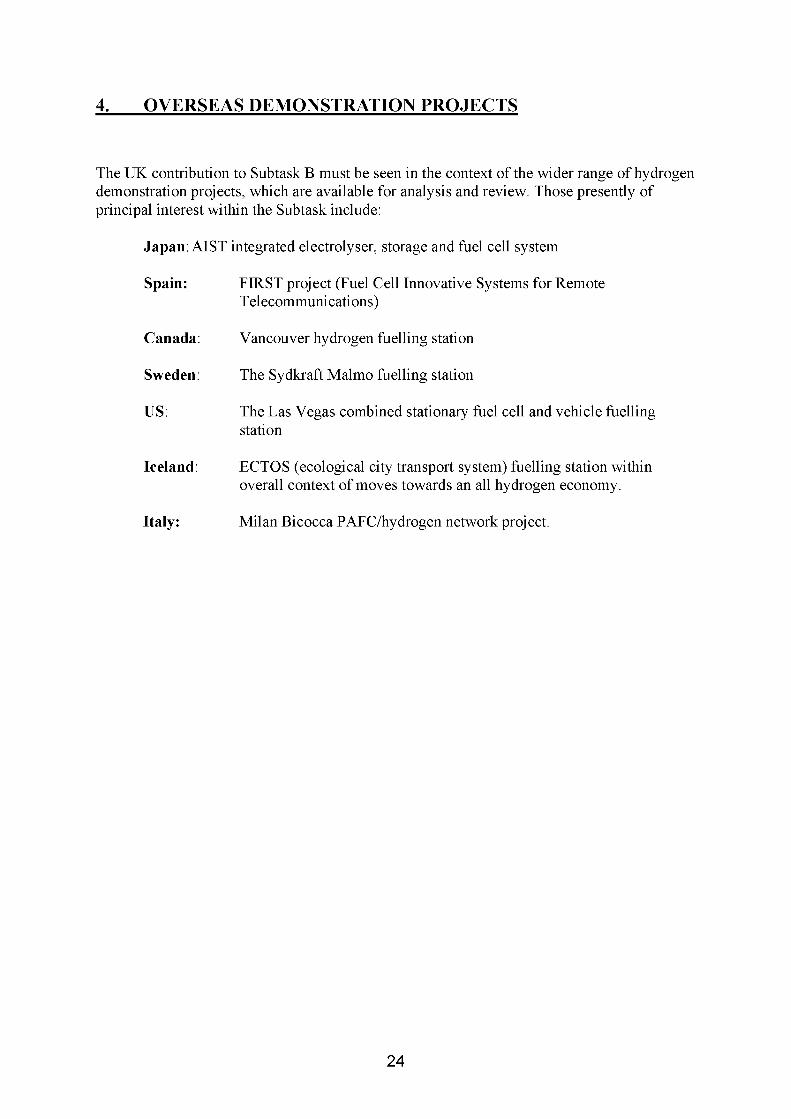
The UK contribution to Subtask B must be seen in the context of the wider range of hydrogen demonstration projects, which are available for analysis and review. Those presently of principal interest within the Subtask include:
Japan: AIST integrated electrolyser, storage and fuel cell system
Spain: FIRST project (Fuel Cell Innovative Systems for RemoteTelecommunications)
Canada: Vancouver hydrogen fuelling station
Sweden: The Sydkraft Malmo fuelling station
US: The Las Vegas combined stationary fuel cell and vehicle fuelling station
Iceland: ECTOS (ecological city transport system) fuelling station within overall context of moves towards an all hydrogen economy.
Italy: Milan Bicocca PAFC/hydrogen network project.
24

5. SELECTION OF CANDIDATE UK PROJECTS FOR MOREDETAILED ANALYSIS AND REVIEW UNDER TASK 18
Table 5.1 provides a summary of the various UK hydrogen related demonstration schemes discussed above.
Table 5.1: Summary of Principal UK Hydrogen Related Demonstration Projects
Demonstration Status TypeHackney CUTE refuelling stationHornchurch CUTE refuelling station
Temporary installation
Under construction
Re-fuelling station
Re-fuelling stationHARI Project Early operational Integrated hydrogen/renewables
systemHunterston Hydrogen Project
Proposed Large scale integrated hydrogen/renewables system
PURE Project Under construction Integrated community energy hydrogen/renewables system, with vehicular hydrogen offtake
Tees Valley Hydrogen Project
Operational: Variable Message SignLighthouseVisitor centre
Planned/proposed: Small Scale CHPLarge Scale CHPFleet and fuellingHydrogen greeningWind hydrogen
Hydrogen Office Planned/proposed Integrated hydrogen office energy system
CymruH2Wales Planned/proposed Various projects, including hydrogen production and fuelling, power generation and marine
INEOS Chlor Under investigation Off-gas fuelled stationary fuel cell
Fuel Cell House Early operational Stationary fuel cell CHPLondon Hydrogen Partnership
Proposed Various projects in relational to infra-structure, stationary and transport applications
The above projects may be reviewed, relative to the Task 18 selection criteria defined in Section 3, i.e. “integrated hydrogen systems, which shall be available for analysis and review during the three year currency of Subtask B”.
25

Notwithstanding the identification of six existent hydrogen related demonstration projects, only the HARI project satisfies the requirement for “integrated hydrogen systems6 ”.
However, if other project developments are considered, which are likely to be realised and to provide data within the three year currency of Task 18 (i.e. to December 2006), then the Hornchurch re-fuelling station and the PURE project may also be included. These latter two projects are both scheduled for completion and commissioning, early 2005.
A far higher degree of uncertainty is attached to the timing of the various other developments identified, particularly in relation to the possibility of their producing operational data, consistent with the timescales of Task 18.
This therefore results in the identification of three UK candidate demonstration projects, suitable for in-depth analysis, review and information exchange under the auspices of Subtask B, namely the HARI project, the PURE project and the Hornchurch CUTE refuelling station. Agreement has been reached with the key stakeholders in all three of these developments, in relation to their participation in the Subtask B demonstration project analysis framework. The inclusion of these three projects within the overall Subtask B demonstration project analysis framework is also entirely consistent with the wider objective of Subtask B, i.e. to populate the evaluation matrix as shown in Table 3.1 with representative examples of demonstration projects.
6 The three Tees Valley demonstrations and the Fuel Cell House all represent examples of hydrogen fuelled fuel cells systems, fed from supplies of compressed gaseous hydrogen. The Hackney refuelling station represents a short term temporary installation only, pending the construction of that at Hornchurch.
26

6. ANALYSIS FRAMEWORK
The analyses of the three preferred UK case study demonstration will address energy efficiency considerations, environmental impact, economic impact, capital and operating costs, planning aspects, health, safety, regulatory and licensing issues and other relevant criteria. The analyses themselves will be performed within the context of an overall analysis framework, as agreed between the various Subtask B Participants.
The analysis of the Hornchurch CUTE hydrogen bus re-fuelling station will form one part of a larger series of analyses of hydrogen re-fuelling stations, conducted within the Subtask. Areas of specific interest within such analyses will include:
• refuelling station aims and objectives (e.g. advancing the technology, limiting risk, limiting cost, demonstrating safety etc)
• development of the safety case
• the planning process
• system performance and operation
• the hydrogen supply chain
• hydrogen station utilisation
The complementary analyses of the HARI and PURE projects will aim to characterise the performance of the systems across a full spectrum of their operational envelopes, paying particular attention to the following parameters:-
• time series analyses of energy demand profiles, typically on hourly/seasonal bases
• time series analyses of renewable resource energy inputs, again on hourly and seasonal bases
• analyses of performance of principal sub-systems, including electrolyser, storage and fuel cell sub-systems
• overall control strategy adopted
All the in-depth analyses will aim to identify the key lessons learnt, for future implementations and to compare UK custom and practice, with that achieved overseas. The work completed to date has provided a firm foundation for such analyses, which can now be built upon over the next two years of Task 18.
27

7. CONCLUSIONS
7.1 The UK has a small but significant number of hydrogen related demonstration projects, either already constructed and operational, planned or proposed.
7.2 Compressed gaseous hydrogen fuelled fuel cell installations represent the majority of implementations to date, noting that these are expedient in developing a first level of hydrogen and fuel cell related operational experience, but at a manageable level of financial commitment.
7.3 The HARI project, as implemented at West Beacon Farm, Leics., represents the sole UK example of an integrated renewable energy/hydrogen system implemented to date. As such, it is eminently suitable for inclusion in the Task 18 Subtask B analysis framework.
7.4 Early operational experience, gained in relation to HARI, has already identified electrolyser performance, when subjected to highly variable renewables related input loadings, to be less than satisfactory.
7.5 Anticipated developments, which are projected to be commissioned within the next six months, include the CUTE re-fuelling station in Essex and the PURE project, in Unst, Shetland. Each of these projects is technically significant and of considerable interest within the context of Subtask B.
28
8. RECOMMENDATIONS FOR FUTURE WORK
8.1 The HARI, PURE and Hornchurch CUTE projects should form the principal UK contributions for analysis and review under Task 18’s Subtask B work programme.
8.2 The UK should also consider participating in the Subtask A programme of work, consistent with the other Participants in Task 18.
8.3 Every effort should be made to learn from the current tranche of UK and overseas demonstration projects, with a view to creating a truly sustainable level of national expertise in relation to the implementation of hydrogen systems.
8.4 There is a need for R&D in relation to enhancing the performance of electrolyser systems, when operating under highly variable input loadings.
8.5 Future UK demonstration projects should include larger scale production/storage systems, with fuel off-takes into the transport chain, consistent with recommendations for Governmental policy formulation in this area (19).
29

REFERENCES
1. All aboard the first zero-emission fuel cell buses. Transport for London Press Release, 16th December 2003.
2. Planning row disrupts fuel cell bus scheme. Professional Engineering, 16th January 2004.
3. CUTE Planning Application. Mumford, J., H2 NET AGM, Rutherford Appleton Laboratory, 14th July 2004.
4. Welcome to West Beacon Farm. Information Leaflet (undated).
5. West Beacon Farm Hydrogen Project. Gammon, R. H2 NET AGM, Rutherford Appleton Laboratory, 14th July 2004
6. The Hydrogen Economy Comes to the UK. Gammon, R. Fuel Cell Today, June 2004.
7. www.wind-hydrogen.com/proiects/PDF/Hunterston.pdf
8. Wind Hydrogen, Delivering the Energy White Paper. Pritchard, D.Institution of Electrical Engineers Seminar on Challenges of the Energy White Paper, Hay dock Park, Lancs., 11th November 2003.
9. Application of Hydrogen Storage for Wind Power-Current Projects,Pritchard, D. DTI Energy Storage Workshop, London, 13th July 2004.
10. www.pure.shetland.co.uk
11. PURE: Promoting Unst’s Renewable Energy. Information Leaflet, May 2004
12. The Challenge of Creating a Viable Fuel Cell Industry: Making it Happen in the Tees Valley. Autherson, J. Mayo, B.J and White D. Eighth Grove Fuel Cell Symposium, London, September 2003.
13. Teeside Hydrogen. A Regional Approach to Effective Applications, the Opportunities and Problems. Mayo, B. H2 NET AGM, Rutherford Appleton Laboratory, 14th July 2004
14. Hydrogen and Wales. A Vision of the Hydrogen Economy in Wales. Report No. 3, University of Glamorgan, November 2004.
30

15. Looking at the UK’s First Fuel Cell Powered Home. Adamson, K. Fuel Cell Today, January 2005.
16. The Hydrogen Office. Undated Information Leaflet. Business Environment Partnership, Dalkeith.
17. INEOS Chlor, Hydrogenics, Stopford Projects and The Carbon Trust to Collaborate on Large Scale Fuel Cell Installation Feasibility Study. INEOS Chlor Press Release, November 2004.
18. The London Hydrogen Partnership. www.lhp.org.uk. January 2005
19. Overview of the UK’s Strategic Framework for Hydrogen Energy. E4 Tech, Eoin Lees Energy and Element Energy, December 2004.
ACKNOWLEDGEMENTS
The writer acknowledges the assistance and contribution freely provided by all the various parties, organisations and individuals contacted, during the discharge of the first year of the UK Task 18 Participating Agency.
31