Embed Size (px)
Citation preview
© 2017 Fire Protection Research Foundation
1 Batterymarch Park, Quincy, MA 02169-7417, USA Email: [email protected] Web: nfpa.org/foundation
Evaluation of LPG Pool Fire Heat Flux – A Literature Review FINAL REPORT BY:
Hang Yi, PhD Student Sam Wang, PhD, PE, CSP Fire Protection and Safety Engineering, Oklahoma State University, OK March 2017
TECHNICAL NOTES

—— Page ii ——
—— Page iii ——
FOREWORD Liquefied Petroleum Gas (LPG) is used widely in a large number of applications, including utility,
cooking and heating appliances. The main components of LPG are propane and butane, which
can be used safely if risks can be managed in acceptable levels. However, LPG may leak and a
pool fire may occur if ignition sources are existed. The heat flux from the pool fire will increase
personnel risks and cause significant damages to individuals, process equipment, storage tanks
and appliances. Therefore, appropriate management of these risks is a critical part throughout
the processes of production, transportation and utilization of LPG.
In order to have a better understanding of the heat flux of LPG pool fires and determine the
acceptable separation distance between the vaporizer and LPG storage tanks, this research tries
to collect available experimental data of LPG pool fires. All the content, perspectives and
conclusions are strictly based on the literature data and just serviced to this research committee.
Thanks to all original authors for producing these data and theoretical models in this report.
Contributions from all technical panel members and NFPA staff are greatly appreciated.
The Fire Protection Research Foundation expresses gratitude to the report authors Hang Yi and
Sam Wang, who are with the Fire Protection and Safety Engineering department, Oklahoma State
University, OK. The Research Foundation appreciates the guidance provided by the Project
Technical Panelists, and all others that contributed to this research effort. Thanks are also
expressed to the National Fire Protection Association (NFPA) for providing the project funding
through the NFPA Annual Research Fund.
The content, opinions and conclusions contained in this report are solely those of the authors and
do not necessarily represent the views of the Fire Protection Research Foundation, NFPA,
Technical Panel or Sponsors. The Foundation makes no guaranty or warranty as to the accuracy
or completeness of any information published herein.
About the Fire Protection Research Foundation
The Fire Protection Research Foundation plans,
manages, and communicates research on a broad
range of fire safety issues in collaboration with
scientists and laboratories around the world. The Foundation is an affiliate of NFPA.
About the National Fire Protection Association (NFPA)
Founded in 1896, NFPA is a global, nonprofit organization devoted to eliminating death, injury, property and economic loss due to fire, electrical and related hazards. The association delivers information and knowledge through more than 300 consensus codes and standards, research, training, education, outreach and advocacy; and by partnering with others who share an interest in furthering the NFPA mission.
All NFPA codes and standards can be viewed online for free.
—— Page iv ——
NFPA's membership totals more than 65,000 individuals around the world.
Keywords: LPG, Heat flux, Pool fire, Radiation, Heat Transfer, Separation Distance, Vaporizer, NFPA 58, NFPA 59
Report number: FRPF-2017-04

—— Page v ——
—— Page vi ——
PROJECT TECHNICAL PANEL
Eric Nette, National Fire Protection Association, MA
Kevin L. Ritz, Baltimore Gas & Electric Company, MD
James R. Goodchild, Xcel Energy, MN
Richard G. Fredenburg, Dept. of Agriculture & Consumer services, NC
Richard A. Hoffman, Hoffmann & Feige, NY
PROJECT SPONSORS
National Fire Protection Association

—— Page vii ——
—— Page viii ——
Final Report
Evaluation of LPG Pool Fire Heat Flux – A Literature
Review
Prepared by
Hang Yi, PhD student
Sam Wang, PhD, PE, CSP
Dale F. Janes Endowed Associate Professor
Fire Protection and Safety Engineering Technology
Oklahoma State University, OK
March 2017
I
Preface
Liquefied Petroleum Gas (LPG) is used widely in a large number of applications, including
utility, cooking and heating appliances. The main components of LPG are propane and
butane, which can be used safely if risks can be managed in acceptable levels. However,
LPG may leak and a pool fire may occur if ignition sources are existed. The heat flux from
the pool fire will increase personnel risks and cause significant damages to individuals,
process equipment, storage tanks and appliances. Therefore, appropriate management of
these risks is a critical part throughout the processes of production, transportation and
utilization of LPG.
In order to have a better understanding of the heat flux of LPG pool fires and determine
the acceptable separation distance between the vaporizer and LPG storage tanks, this
research tries to collect available experimental data of LPG pool fires. All the content,
perspectives and conclusions are strictly based on the literature data and just serviced to
this research committee.
Thanks to all original authors for producing these data and theoretical models in this report.
Contributions from all technical panel members and NFPA staff are greatly appreciated.
II
Contents
Preface ......................................................................................................................................... I
1. Introduction ........................................................................................................................... 1
1.1 Background ...................................................................................................................... 1
1.2 Objectives ......................................................................................................................... 1
1.3 Scope ................................................................................................................................. 1
2. Definition ................................................................................................................................ 3
2.1 Pool fire ............................................................................................................................ 3
2.2 Pool size ............................................................................................................................ 3
2.3 Burning rate ..................................................................................................................... 3
2.4 Flame shape ...................................................................................................................... 3
2.5 Flame height ..................................................................................................................... 3
2.6 Average emissive power .................................................................................................. 3
2.7 Flame temperature .......................................................................................................... 3
2.8 Flame tilt angle ................................................................................................................ 4
2.9 Geometric view factor ..................................................................................................... 4
2.10 Radiation to surroundings ............................................................................................ 4
2.11 LPG storage tanks (Non-refrigerated) ........................................................................ 4
2.12 Linear scale .................................................................................................................... 4
3. Literature data ....................................................................................................................... 6
3.1 Amount of radiant heat emitted by different sized pool fires ...................................... 6
3.2 Heat flux values causing LPG storage tanks to fail .................................................... 17
3.3 Determining the acceptable separation distance (ASD) ............................................. 19
4. Modelling of heat flux from pool fires to LPG containers ............................................... 20
5. Conclusion and future work ............................................................................................... 21
6. References ........................................................................................................................... 22
Appendix A: Models for Calculating Parameters of LPG Pool Fires ..................................... 25
1. Burning rate ......................................................................................................................... 26
2. Flame height ......................................................................................................................... 27
3. Flame tilt .............................................................................................................................. 28
4. Thermal radiation form pool fires ..................................................................................... 29
4.1 Point source model ........................................................................................................ 29
4.2 Solid flame radiation model .......................................................................................... 29
5. Geometric view factor ......................................................................................................... 31
6. Smoke effects on radiation .................................................................................................. 32

III
7. Radiation to surroundings (Fractional energy radiated by a fire) .................................. 32
1
1. Introduction
1.1 Background
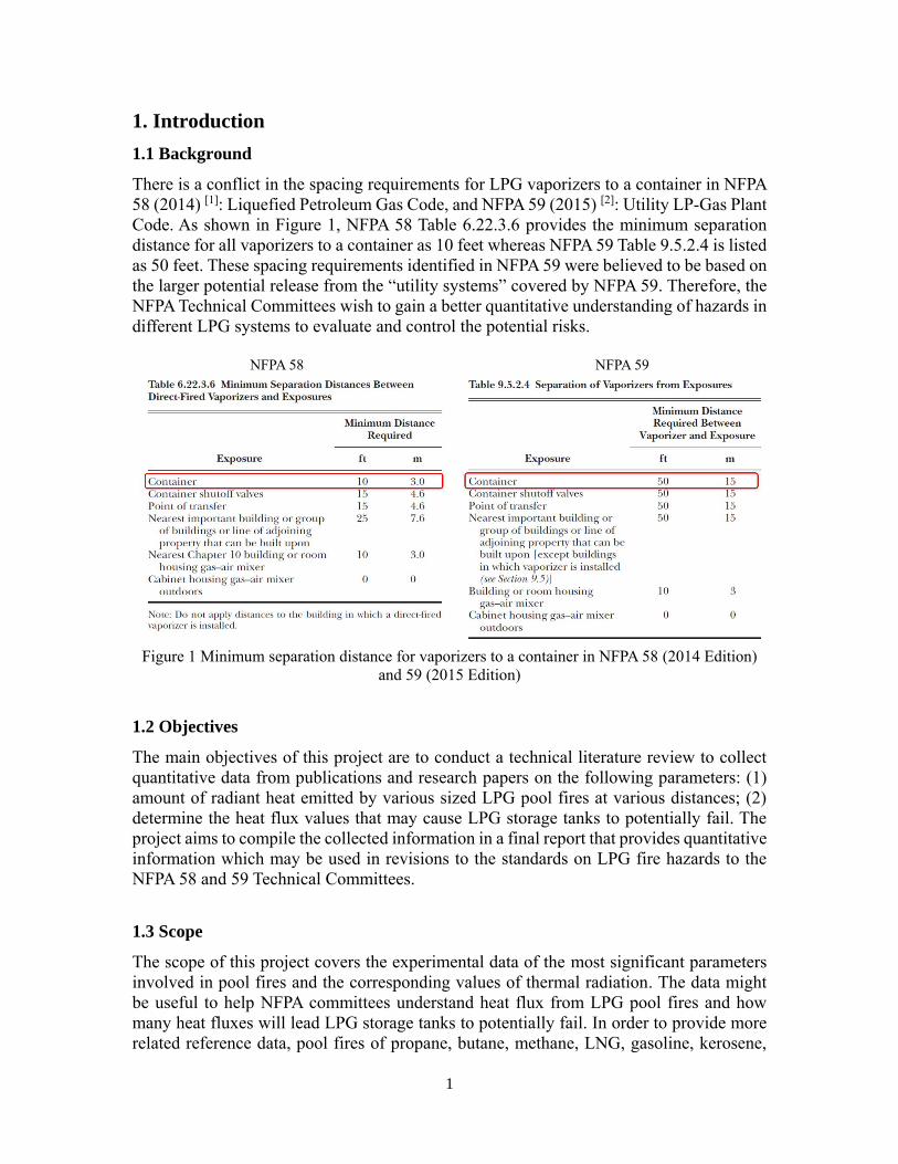
There is a conflict in the spacing requirements for LPG vaporizers to a container in NFPA
58 (2014) [1]: Liquefied Petroleum Gas Code, and NFPA 59 (2015) [2]: Utility LP-Gas Plant
Code. As shown in Figure 1, NFPA 58 Table 6.22.3.6 provides the minimum separation
distance for all vaporizers to a container as 10 feet whereas NFPA 59 Table 9.5.2.4 is listed
as 50 feet. These spacing requirements identified in NFPA 59 were believed to be based on
the larger potential release from the “utility systems” covered by NFPA 59. Therefore, the
NFPA Technical Committees wish to gain a better quantitative understanding of hazards in
different LPG systems to evaluate and control the potential risks.
NFPA 58 NFPA 59
Figure 1 Minimum separation distance for vaporizers to a container in NFPA 58 (2014 Edition)
and 59 (2015 Edition)
1.2 Objectives
The main objectives of this project are to conduct a technical literature review to collect
quantitative data from publications and research papers on the following parameters: (1)
amount of radiant heat emitted by various sized LPG pool fires at various distances; (2)
determine the heat flux values that may cause LPG storage tanks to potentially fail. The
project aims to compile the collected information in a final report that provides quantitative
information which may be used in revisions to the standards on LPG fire hazards to the
NFPA 58 and 59 Technical Committees.
1.3 Scope
The scope of this project covers the experimental data of the most significant parameters
involved in pool fires and the corresponding values of thermal radiation. The data might
be useful to help NFPA committees understand heat flux from LPG pool fires and how
many heat fluxes will lead LPG storage tanks to potentially fail. In order to provide more
related reference data, pool fires of propane, butane, methane, LNG, gasoline, kerosene,
2
JP-4, JP-5, hexane and diesel are also considered in this report. These extra data might help
the committees make decisions when they evaluate the heat flux values of LPG pool fires
and consider revisions to the codes. It should be pointed out that there is little literature on
the storage tanks or containers being heated by the heat flux of LPG pool fires. Almost all
collected literature only shows the situation that the storage container or tank is heated in
engulfing fires, which is different from the condition under a specific pool fire.
However, this project also collects some classical pool fire models and provides significant
instructions that can help the committee to obtain a large amount of theoretical data, which
are beyond the scope of this project. More research on pool fire models should be carried
out as future work.
3
2. Definition
LPG pool fire is a complicated combustion processing affected by many parameters,
including pool size, burning rate, flame shape, flame height, emissive power, flame
temperature, flame tilt, geometric view factor, etc. In order to have a profound
understanding of the heat flux from LPG pool fires to surroundings, all these parameters
should be considered and their definitions are listed below.
2.1 Pool fire
A pool fire is defined as a buoyant diffusion flame in which the fuel is configured
horizontally. The fuel is not limited to liquid, it may be a gas or solid.
2.2 Pool size
Pool size, D (m), is also called pool diameter. LPG pool fire has an arbitrary geometry, for
simplicity, most studies consider a circular configuration characterized by a single
geometrical scale.
2.3 Burning rate
Burning rate, �̇�" (kg/m2 s), of LPG pool fires is the combustion rate of fuels which is
commonly represented by the mass loss rate per unit area.
2.4 Flame shape
Flame shape of pool fires is generally considered as a three-dimensional cylindrical model
with radiation and the main parameters of which includes the flame chassis diameter, flame
height and angle. In pool fires, the flame chassis diameter is slightly larger than the pool
diameter. However, in order to simplify the calculation, it is generally believed the flame
chassis diameter is equal to the pool diameter.
2.5 Flame height
Flame height, H (m), is the visible edge of flame luminescence. It is often replaced with a
non-dimensional flame height, H/D.
2.6 Average emissive power
Average emissive power, E (kW/m2), is also called average surface emissive power (SEP),
which means the average emissive power of the flame on the flame surface.
2.7 Flame temperature
Flame temperature, T (K), is the temperature of the flame surface. It is a constant when the
pool fire is under steady state.
4
2.8 Flame tilt angle
Flame tilt angle, θ, is the angle of inclination of the flame in a LPG pool fire under the
crosswind, which is correlated from the function of crosswind velocity.
2.9 Geometric view factor
Geometric view factor, F, is defined as the fraction of energy radiated by the fire that is
intercepted by the receiving object.
2.10 Radiation to surroundings
Radiation to surroundings, �̇�" (kW/m2), or heat flux to objects, means the heat flux to an
object in a distance S (m) from the center of a pool fire.
2.11 LPG storage tanks (Non-refrigerated)
LPG storage tanks are pressure vessels that hold liquefied LPG, or compressed gases. In
US, LPG storage tanks are designed and constructed to ASME (Section VIII, Division Ι),
NFPA 58 and NFPA 59.
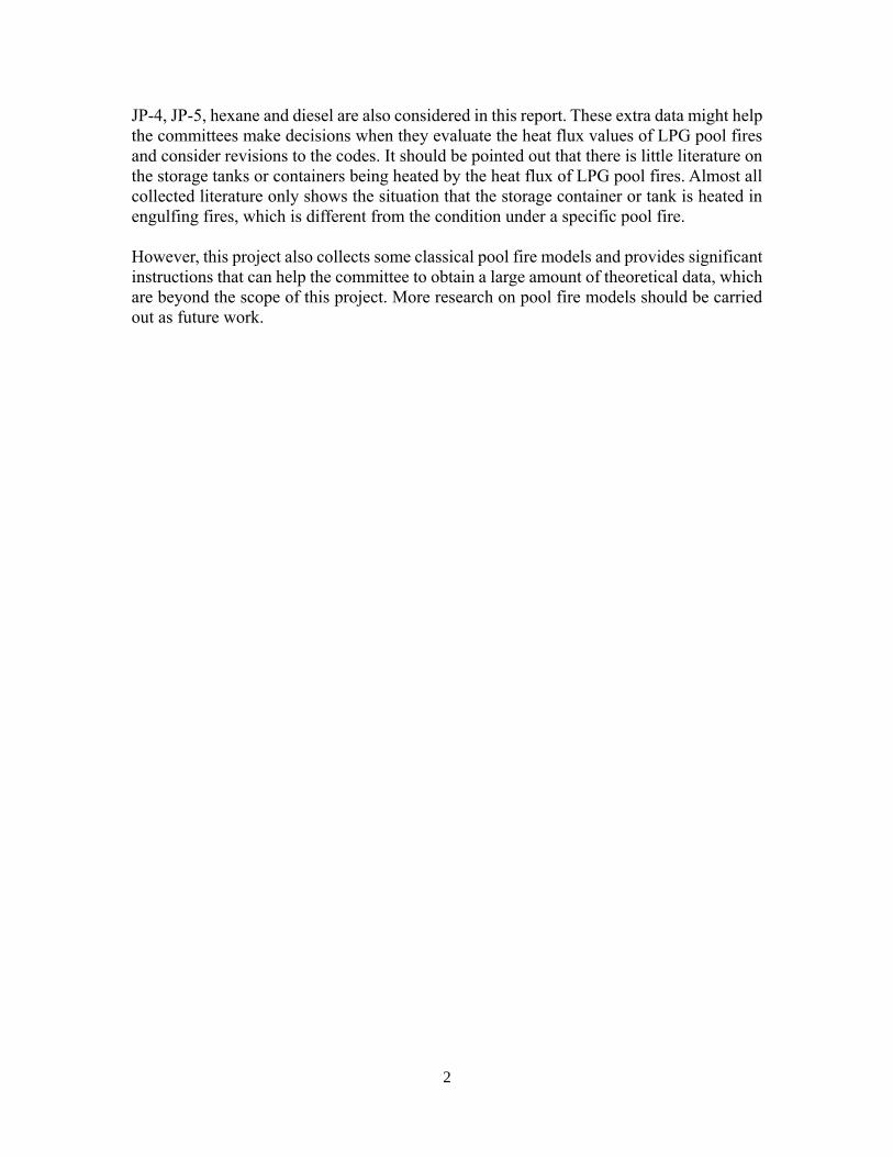
2.12 Linear scale
Figure 2 Sketches showing h and d in tanks with liquids
5
Linear scale is to describe how full a LPG storage tank is, often using h/d to replace h in
the industry, where h is the liquid height and d is the diameter for a cylindrical or spherical
container shown in Figure 2.
6
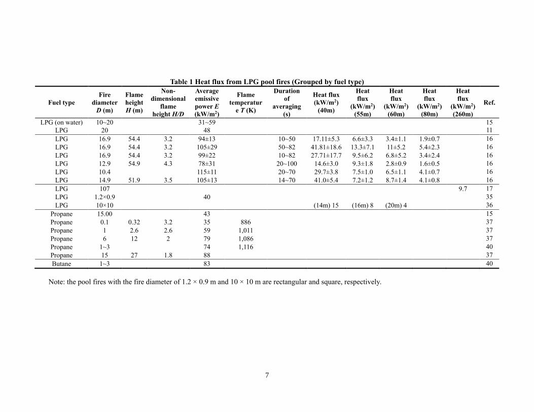
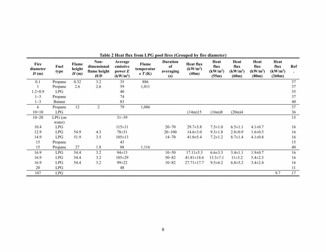
3. Literature data
This section includes three parts: (1) the heat flux from different pool fires at various
distances; (2) the amount of heat flux values that will lead storage tanks to potentially fail,
(3) acceptance separation distance (ASD) for LPG pool fires.
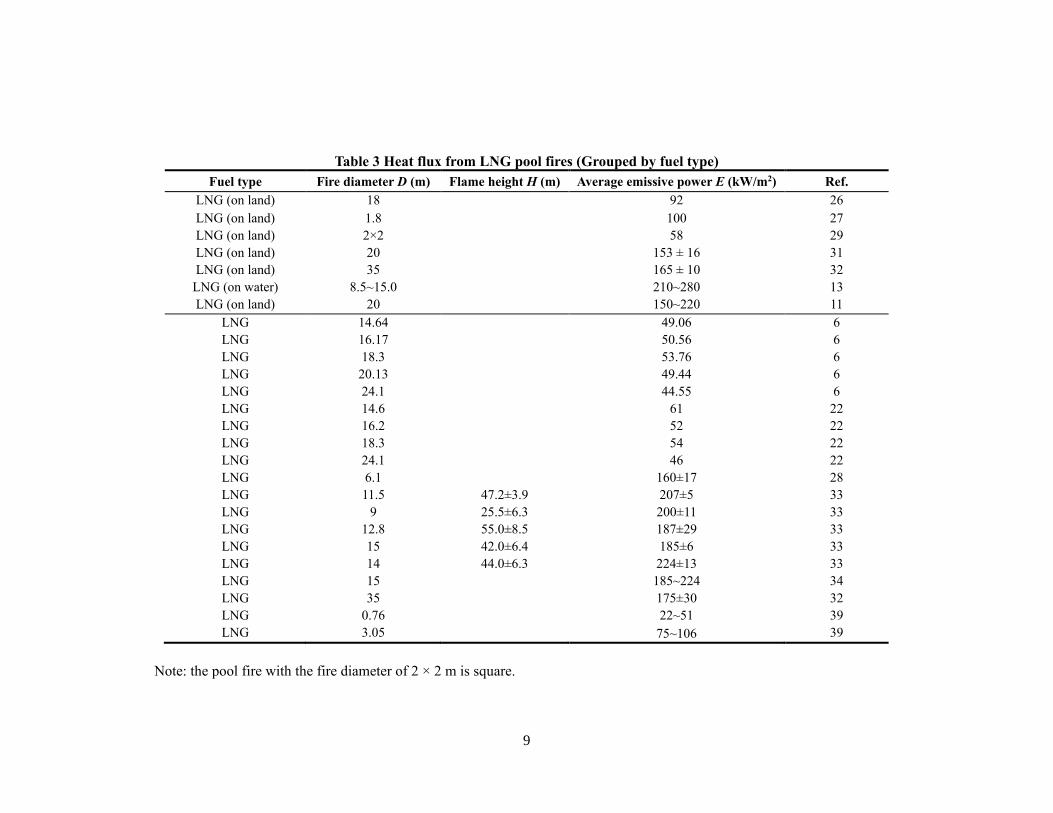
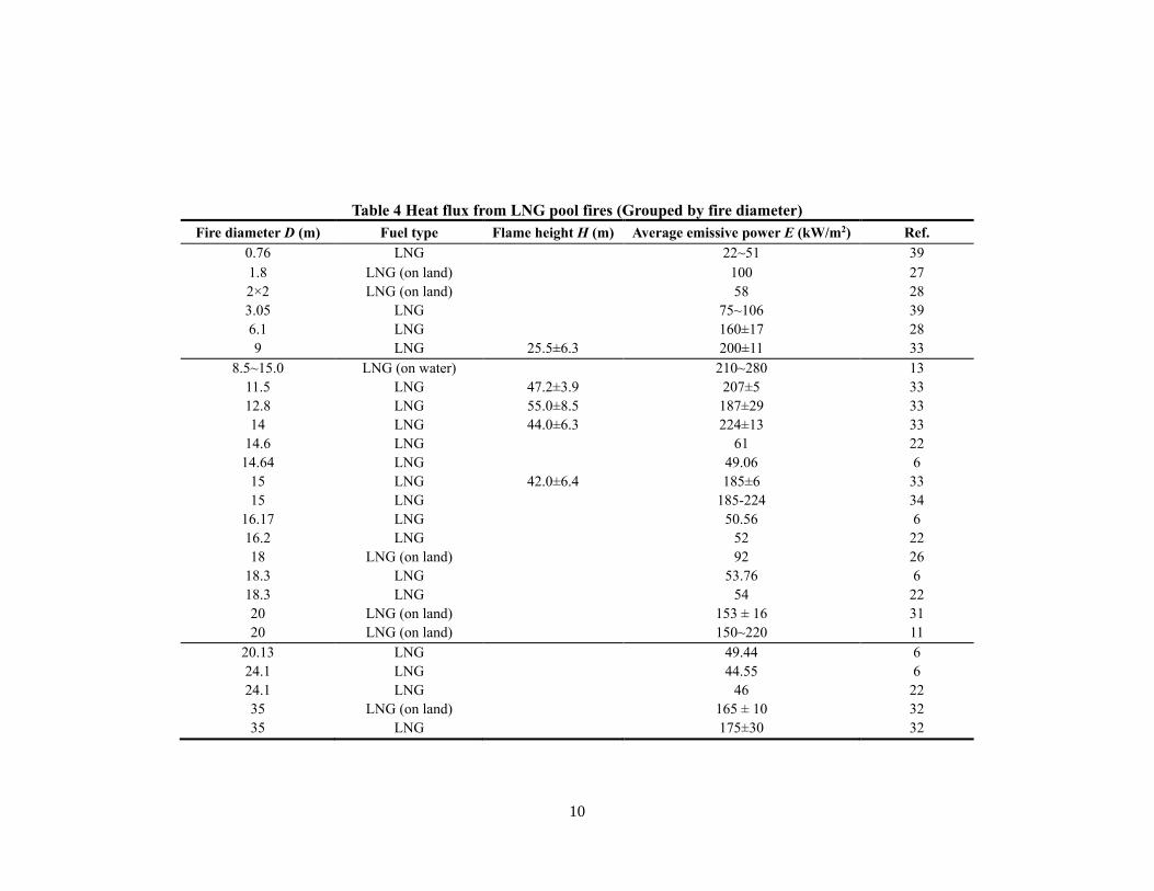
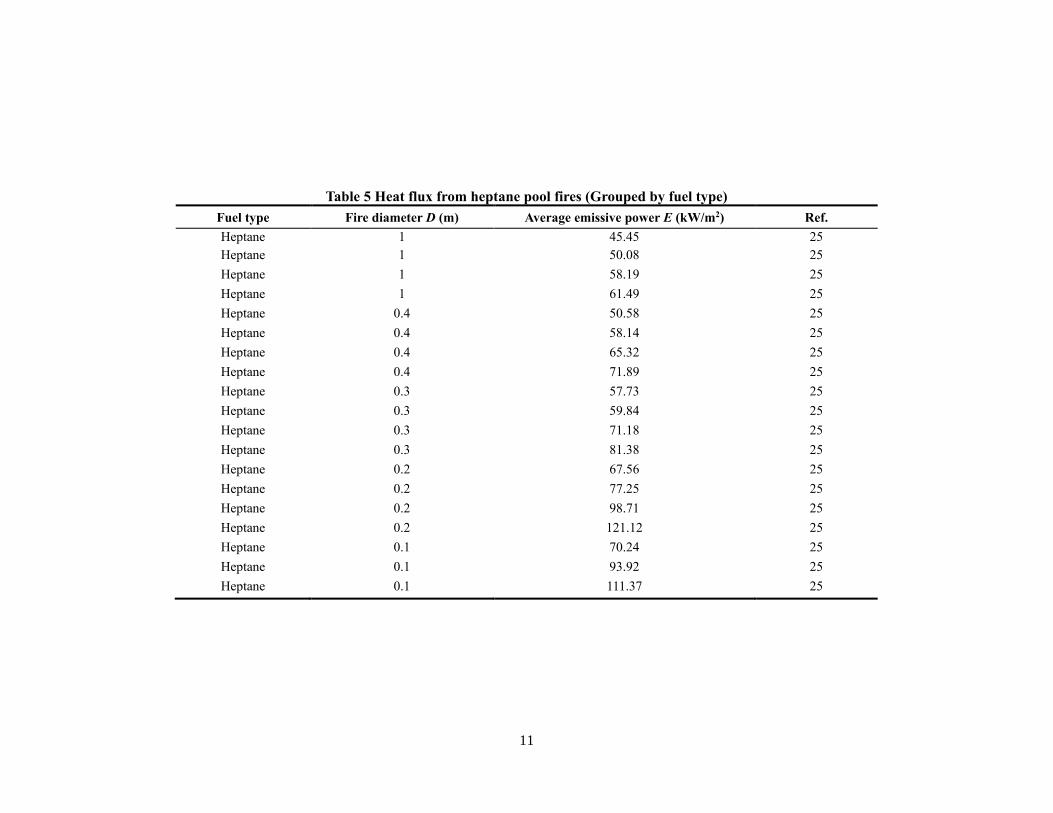
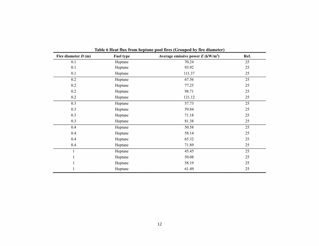
3.1 Amount of radiant heat emitted by different sized pool fires
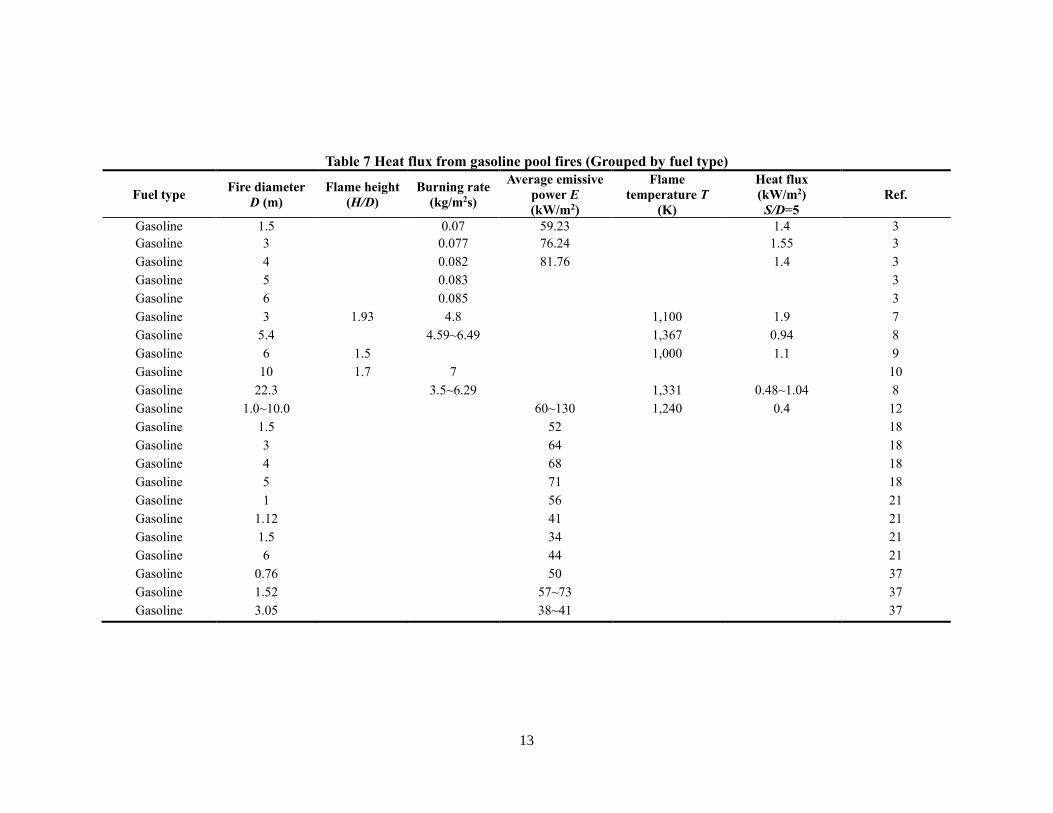
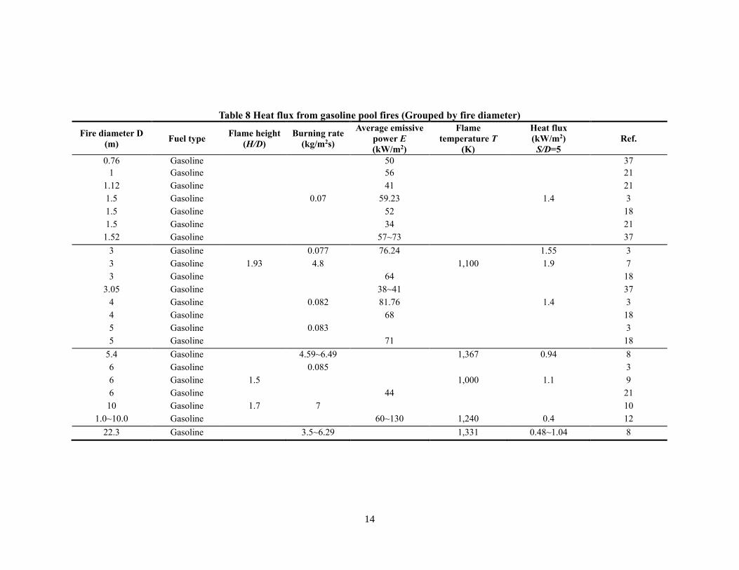
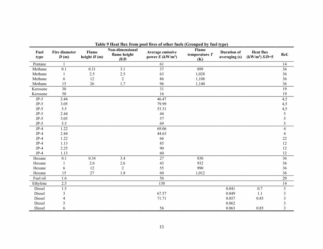
This report gives pool fire data of 13 types of fuels, and each fuel is grouped by fuel type
and pool fire size separately. Table 1 and Table 2 show experimental data from LPG pool
fires. Table 3 and Table 4 describe experimental data from LNG pool fires. Table 5 and
Table 6 present experimental information from heptane pool fires. Table 7 and Table 8 show
heat flux from gasoline, and Table 9 and Table 10 show other fuels’ information.
In Table 1, for the pool fire sizes from 0.1 m to 10 m, the average emissive power is ranging
from 35 kW/m2 to 79 kW/m2 according to the experimental data, and when the size is from
10 m to 20 m, the counterpart power is ranging from 47 kW/m2 to 134 kW/m2. When the
shape of liquid pools is rectangular or square [35, 36], the diameters of these pool fires can
be transferred to equivalent diameters 1 m and 10 m, respectively.
Mudan, K. S. [16] gives relatively complete data for LPG pool fires with the pool size from
10.4 m to 16.9 m. The heat flux at the distances of 40 m, 55 m, 60 m and 80 m to the pool
fire center has been measured clearly in these experiments. The heat flux decreases from
60 kW/m2 to 2 kW/m2 as the distance increases from 40 m to 80 m. For the diameter larger
than 100 m, NISTIR 6546 [17] shows the heat flux is 9.7 kW/m2 at the distance of 260 m to
the fire center with the largest pool size of 107 m.
7
Table 1 Heat flux from LPG pool fires (Grouped by fuel type)
Fuel type
Fire
diameter
D (m)
Flame
height
H (m)
Non-
dimensional
flame
height H/D
Average
emissive
power E
(kW/m2)
Flame
temperatur
e T (K)
Duration
of
averaging
(s)
Heat flux
(kW/m2)
(40m)
Heat
flux
(kW/m2)
(55m)
Heat
flux
(kW/m2)
(60m)
Heat
flux
(kW/m2)
(80m)
Heat
flux
(kW/m2)
(260m)
Ref.
LPG (on water) 10~20 31~59 15
LPG 20 48 11
LPG 16.9 54.4 3.2 94±13 10~50 17.11±5.3 6.6±3.3 3.4±1.1 1.9±0.7 16
LPG 16.9 54.4 3.2 105±29 50~82 41.81±18.6 13.3±7.1 11±5.2 5.4±2.3 16
LPG 16.9 54.4 3.2 99±22 10~82 27.71±17.7 9.5±6.2 6.8±5.2 3.4±2.4 16
LPG 12.9 54.9 4.3 78±31 20~100 14.6±3.0 9.3±1.8 2.8±0.9 1.6±0.5 16
LPG 10.4 115±11 20~70 29.7±3.8 7.5±1.0 6.5±1.1 4.1±0.7 16
LPG 14.9 51.9 3.5 105±13 14~70 41.0±5.4 7.2±1.2 8.7±1.4 4.1±0.8 16
LPG 107 9.7 17
LPG 1.2×0.9 40 35
LPG 10×10 (14m) 15 (16m) 8 (20m) 4 36
Propane 15.00 43 15
Propane 0.1 0.32 3.2 35 886 37
Propane 1 2.6 2.6 59 1,011 37
Propane 6 12 2 79 1,086 37
Propane 1~3 74 1,116 40
Propane 15 27 1.8 88 37
Butane 1~3 83 40
Note: the pool fires with the fire diameter of 1.2 × 0.9 m and 10 × 10 m are rectangular and square, respectively.
8
Table 2 Heat flux from LPG pool fires (Grouped by fire diameter)
Fire
diameter
D (m)
Fuel
type
Flame
height
H (m)
Non-
dimensional
flame height
H/D
Average
emissive
power E
(kW/m2)
Flame
temperatur
e T (K)
Duration
of
averaging
(s)
Heat flux
(kW/m2)
(40m)
Heat
flux
(kW/m2)
(55m)
Heat
flux
(kW/m2)
(60m)
Heat
flux
(kW/m2)
(80m)
Heat
flux
(kW/m2)
(260m)
Ref
.
0.1 Propane 0.32 3.2 35 886 37
1 Propane 2.6 2.6 59 1,011 37
1.2×0.9 LPG 40 35
1~3 Propane 74 37
1~3 Butane 83 40
6 Propane 12 2 79 1,086 37
10×10 LPG (14m)15 (16m)8 (20m)4 36
10~20 LPG (on
water)
31~59 15
10.4 LPG 115±11 20~70 29.7±3.8 7.5±1.0 6.5±1.1 4.1±0.7 16
12.9 LPG 54.9 4.3 78±31 20~100 14.6±3.0 9.3±1.8 2.8±0.9 1.6±0.5 16
14.9 LPG 51.9 3.5 105±13 14~70 41.0±5.4 7.2±1.2 8.7±1.4 4.1±0.8 16
15 Propane 43 15
15 Propane 27 1.8 88 1,116 40
16.9 LPG 54.4 3.2 94±13 10~50 17.11±5.3 6.6±3.3 3.4±1.1 1.9±0.7 16
16.9 LPG 54.4 3.2 105±29 50~82 41.81±18.6 13.3±7.1 11±5.2 5.4±2.3 16
16.9 LPG 54.4 3.2 99±22 10~82 27.71±17.7 9.5±6.2 6.8±5.2 3.4±2.4 16
20 LPG 48 11
107 LPG 9.7 17
9
Table 3 Heat flux from LNG pool fires (Grouped by fuel type)
Fuel type Fire diameter D (m) Flame height H (m) Average emissive power E (kW/m2) Ref.
LNG (on land) 18 92 26
LNG (on land) 1.8 100 27
LNG (on land) 2×2 58 29
LNG (on land) 20 153 ± 16 31
LNG (on land) 35 165 ± 10 32
LNG (on water) 8.5~15.0 210~280 13
LNG (on land) 20 150~220 11
LNG 14.64 49.06 6
LNG 16.17 50.56 6
LNG 18.3 53.76 6
LNG 20.13 49.44 6
LNG 24.1 44.55 6
LNG 14.6 61 22
LNG 16.2 52 22
LNG 18.3 54 22
LNG 24.1 46 22
LNG 6.1 160±17 28
LNG 11.5 47.2±3.9 207±5 33
LNG 9 25.5±6.3 200±11 33
LNG 12.8 55.0±8.5 187±29 33
LNG 15 42.0±6.4 185±6 33
LNG 14 44.0±6.3 224±13 33
LNG 15 185~224 34
LNG 35 175±30 32
LNG 0.76 22~51 39
LNG 3.05 75~106 39
Note: the pool fire with the fire diameter of 2 × 2 m is square.
10
Table 4 Heat flux from LNG pool fires (Grouped by fire diameter)
Fire diameter D (m) Fuel type Flame height H (m) Average emissive power E (kW/m2) Ref.
0.76 LNG 22~51 39
1.8 LNG (on land) 100 27
2×2 LNG (on land) 58 28
3.05 LNG 75~106 39
6.1 LNG 160±17 28
9 LNG 25.5±6.3 200±11 33
8.5~15.0 LNG (on water) 210~280 13
11.5 LNG 47.2±3.9 207±5 33
12.8 LNG 55.0±8.5 187±29 33
14 LNG 44.0±6.3 224±13 33
14.6 LNG 61 22
14.64 LNG 49.06 6
15 LNG 42.0±6.4 185±6 33
15 LNG 185-224 34
16.17 LNG 50.56 6
16.2 LNG 52 22
18 LNG (on land) 92 26
18.3 LNG 53.76 6
18.3 LNG 54 22
20 LNG (on land) 153 ± 16 31
20 LNG (on land) 150~220 11
20.13 LNG 49.44 6
24.1 LNG 44.55 6
24.1 LNG 46 22
35 LNG (on land) 165 ± 10 32
35 LNG 175±30 32
11
Table 5 Heat flux from heptane pool fires (Grouped by fuel type)
Fuel type Fire diameter D (m) Average emissive power E (kW/m2) Ref.
Heptane 1 45.45 25
Heptane 1 50.08 25
Heptane 1 58.19 25
Heptane 1 61.49 25
Heptane 0.4 50.58 25
Heptane 0.4 58.14 25
Heptane 0.4 65.32 25
Heptane 0.4 71.89 25
Heptane 0.3 57.73 25
Heptane 0.3 59.84 25
Heptane 0.3 71.18 25
Heptane 0.3 81.38 25
Heptane 0.2 67.56 25
Heptane 0.2 77.25 25
Heptane 0.2 98.71 25
Heptane 0.2 121.12 25
Heptane 0.1 70.24 25
Heptane 0.1 93.92 25
Heptane 0.1 111.37 25
12
Table 6 Heat flux from heptane pool fires (Grouped by fire diameter)
Fire diameter D (m) Fuel type Average emissive power E (kW/m2) Ref.
0.1 Heptane 70.24 25
0.1 Heptane 93.92 25
0.1 Heptane 111.37 25
0.2 Heptane 67.56 25
0.2 Heptane 77.25 25
0.2 Heptane 98.71 25
0.2 Heptane 121.12 25
0.3 Heptane 57.73 25
0.3 Heptane 59.84 25
0.3 Heptane 71.18 25
0.3 Heptane 81.38 25
0.4 Heptane 50.58 25
0.4 Heptane 58.14 25
0.4 Heptane 65.32 25
0.4 Heptane 71.89 25
1 Heptane 45.45 25
1 Heptane 50.08 25
1 Heptane 58.19 25
1 Heptane 61.49 25
13
Table 7 Heat flux from gasoline pool fires (Grouped by fuel type)
Fuel type Fire diameter
D (m)
Flame height
(H/D)
Burning rate
(kg/m2s)
Average emissive
power E
(kW/m2)
Flame
temperature T
(K)
Heat flux
(kW/m2)
S/D=5
Ref.
Gasoline 1.5 0.07 59.23 1.4 3
Gasoline 3 0.077 76.24 1.55 3
Gasoline 4 0.082 81.76 1.4 3
Gasoline 5 0.083 3
Gasoline 6 0.085 3
Gasoline 3 1.93 4.8 1,100 1.9 7
Gasoline 5.4 4.59~6.49 1,367 0.94 8
Gasoline 6 1.5 1,000 1.1 9
Gasoline 10 1.7 7 10
Gasoline 22.3 3.5~6.29 1,331 0.48~1.04 8
Gasoline 1.0~10.0 60~130 1,240 0.4 12
Gasoline 1.5 52 18
Gasoline 3 64 18
Gasoline 4 68 18
Gasoline 5 71 18
Gasoline 1 56 21
Gasoline 1.12 41 21
Gasoline 1.5 34 21
Gasoline 6 44 21
Gasoline 0.76 50 37
Gasoline 1.52 57~73 37
Gasoline 3.05 38~41 37
14
Table 8 Heat flux from gasoline pool fires (Grouped by fire diameter)
Fire diameter D
(m) Fuel type
Flame height
(H/D)
Burning rate
(kg/m2s)
Average emissive
power E
(kW/m2)
Flame
temperature T
(K)
Heat flux
(kW/m2)
S/D=5
Ref.
0.76 Gasoline 50 37
1 Gasoline 56 21
1.12 Gasoline 41 21
1.5 Gasoline 0.07 59.23 1.4 3
1.5 Gasoline 52 18
1.5 Gasoline 34 21
1.52 Gasoline 57~73 37
3 Gasoline 0.077 76.24 1.55 3
3 Gasoline 1.93 4.8 1,100 1.9 7
3 Gasoline 64 18
3.05 Gasoline 38~41 37
4 Gasoline 0.082 81.76 1.4 3
4 Gasoline 68 18
5 Gasoline 0.083 3
5 Gasoline 71 18
5.4 Gasoline 4.59~6.49 1,367 0.94 8
6 Gasoline 0.085 3
6 Gasoline 1.5 1,000 1.1 9
6 Gasoline 44 21
10 Gasoline 1.7 7 10
1.0~10.0 Gasoline 60~130 1,240 0.4 12
22.3 Gasoline 3.5~6.29 1,331 0.48~1.04 8
15
Table 9 Heat flux from pool fires of other fuels (Grouped by fuel type)
Fuel
type
Fire diameter
D (m)
Flame
height H (m)
Non-dimensional
flame height
H/D
Average emissive
power E (kW/m2)
Flame
temperature T
(K)
Duration of
averaging (s)
Heat flux
(kW/m2) S/D=5 Ref.
Pentane 1 61 14
Methane 0.1 0.31 3.1 37 899 36
Methane 1 2.5 2.5 63 1,028 36
Methane 6 12 2 86 1,108 36
Methane 15 26 1.7 96 1,140 36
Kerosene 30 31 19
Kerosene 50 16 19
JP-5 2.44 46.47 4,5
JP-5 3.05 79.99 4,5
JP-5 5.5 53.31 4,5
JP-5 2.44 44 5
JP-5 3.05 57 5
JP-5 5.5 69 5
JP-4 1.22 69.06 4
JP-4 2.44 44.63 4
JP-4 1.22 66 22
JP-4 1.13 85 12
JP-4 2.25 90 12
JP-4 1.13 60 12
Hexane 0.1 0.34 3.4 27 830 36
Hexane 1 2.6 2.6 43 932 36
Hexane 6 12 2 55 990 36
Hexane 15 27 1.8 60 1,012 36
Fuel oil 1.6 56 20
Ethylene 2.5 130 14
Diesel 1.5 0.041 0.7 3
Diesel 3 67.57 0.049 1.1 3
Diesel 4 71.71 0.057 0.85 3
Diesel 5 0.062 3
Diesel 6 56 0.063 0.85 3
16
Table 10 Heat flux from pool fires of other fuels (Grouped by fire diameter)
Fire
diameter
D (m)
Fuel type Flame
height H (m)
Non-dimensional
flame height
H/D
Average emissive
power E (kW/m2)
Flame
temperature T
(K)
Duration of
averaging (s)
Heat flux
(kW/m2) S/D=5 Ref.
0.1 Methane 0.31 3.1 37 899 36
0.1 Hexane 0.34 3.4 27 830 36
1 Pentane 61 14
1 Methane 2.5 2.5 63 1,028 36
1 Hexane 2.6 2.6 43 932 36
1.13 JP-4 85 12
1.13 JP-4 60 12
1.22 JP-4 69.06 4
1.22 JP-4 66 22
1.5 Diesel 0.041 0.7 3
1.6 Fuel oil 56 20
2.25 JP-4 90 12
2.44 JP-5 46.47 4,5
2.44 JP-5 44 5
2.44 JP-4 44.63 4
2.5 Ethylene 130 14
3 Diesel 67.57 0.049 1.1 3
3.05 JP-5 79.99 4,5
3.05 JP-5 57 5
4 Diesel 71.71 0.057 0.85 3
5 Diesel 0.062 3
5.5 JP-5 53.31 4,5
5.5 JP-5 69 5
6 Methane 12 2 86 1,108 36
6 Hexane 12 2 55 990 36
6 Diesel 56 0.063 0.85 3
15 Methane 26 1.7 96 1,140 36
15 Hexane 27 1.8 60 1,012 36
30 Kerosene 31 19
50 Kerosene 16 19
17
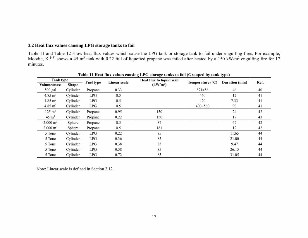
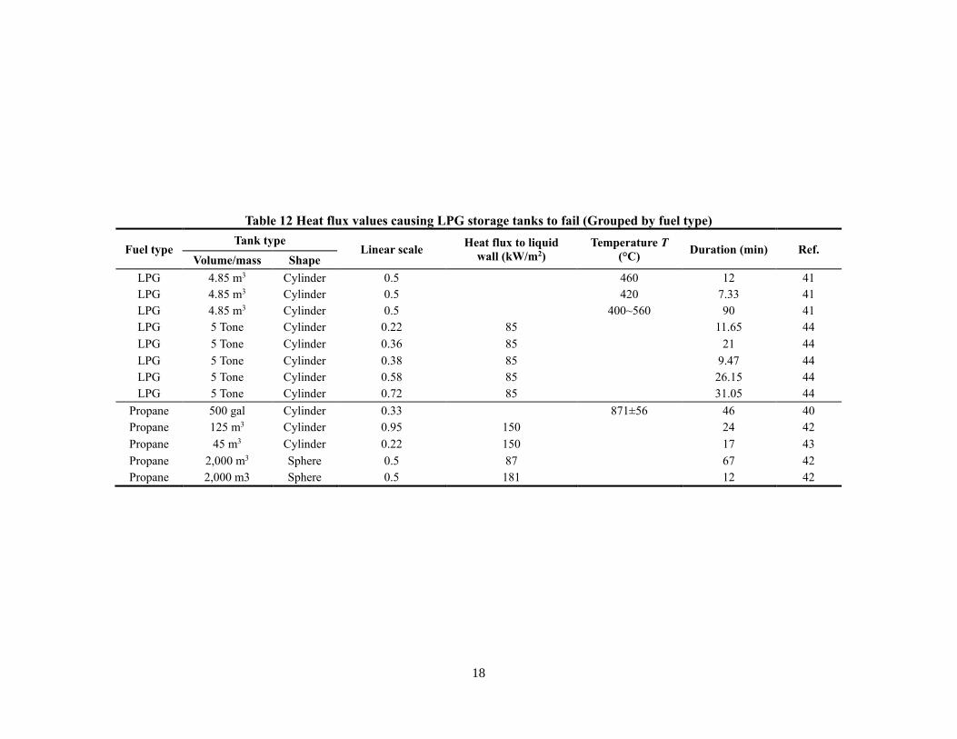
3.2 Heat flux values causing LPG storage tanks to fail
Table 11 and Table 12 show heat flux values which cause the LPG tank or storage tank to fail under engulfing fires. For example,
Moodie, K [43] shows a 45 m3 tank with 0.22 full of liquefied propane was failed after heated by a 150 kW/m2 engulfing fire for 17
minutes.
Table 11 Heat flux values causing LPG storage tanks to fail (Grouped by tank type)
Tank type Fuel type Linear scale
Heat flux to liquid wall
(kW/m2) Temperature (°C) Duration (min) Ref.
Volume/mass Shape
500 gal Cylinder Propane 0.33 871±56 46 40
4.85 m3 Cylinder LPG 0.5 460 12 41
4.85 m3 Cylinder LPG 0.5 420 7.33 41
4.85 m3 Cylinder LPG 0.5 400~560 90 41
125 m3 Cylinder Propane 0.95 150 24 42
45 m3 Cylinder Propane 0.22 150 17 43
2,000 m3 Sphere Propane 0.5 87 67 42
2,000 m3 Sphere Propane 0.5 181 12 42
5 Tone Cylinder LPG 0.22 85 11.65 44
5 Tone Cylinder LPG 0.36 85 21.00 44
5 Tone Cylinder LPG 0.38 85 9.47 44
5 Tone Cylinder LPG 0.58 85 26.15 44
5 Tone Cylinder LPG 0.72 85 31.05 44
Note: Linear scale is defined in Section 2.12.
18
Table 12 Heat flux values causing LPG storage tanks to fail (Grouped by fuel type)
Fuel type Tank type
Linear scale Heat flux to liquid
wall (kW/m2)
Temperature T
(°C) Duration (min) Ref.
Volume/mass Shape
LPG 4.85 m3 Cylinder 0.5 460 12 41
LPG 4.85 m3 Cylinder 0.5 420 7.33 41
LPG 4.85 m3 Cylinder 0.5 400~560 90 41
LPG 5 Tone Cylinder 0.22 85 11.65 44
LPG 5 Tone Cylinder 0.36 85 21 44
LPG 5 Tone Cylinder 0.38 85 9.47 44
LPG 5 Tone Cylinder 0.58 85 26.15 44
LPG 5 Tone Cylinder 0.72 85 31.05 44
Propane 500 gal Cylinder 0.33 871±56 46 40
Propane 125 m3 Cylinder 0.95 150 24 42
Propane 45 m3 Cylinder 0.22 150 17 43
Propane 2,000 m3 Sphere 0.5 87 67 42
Propane 2,000 m3 Sphere 0.5 181 12 42
19
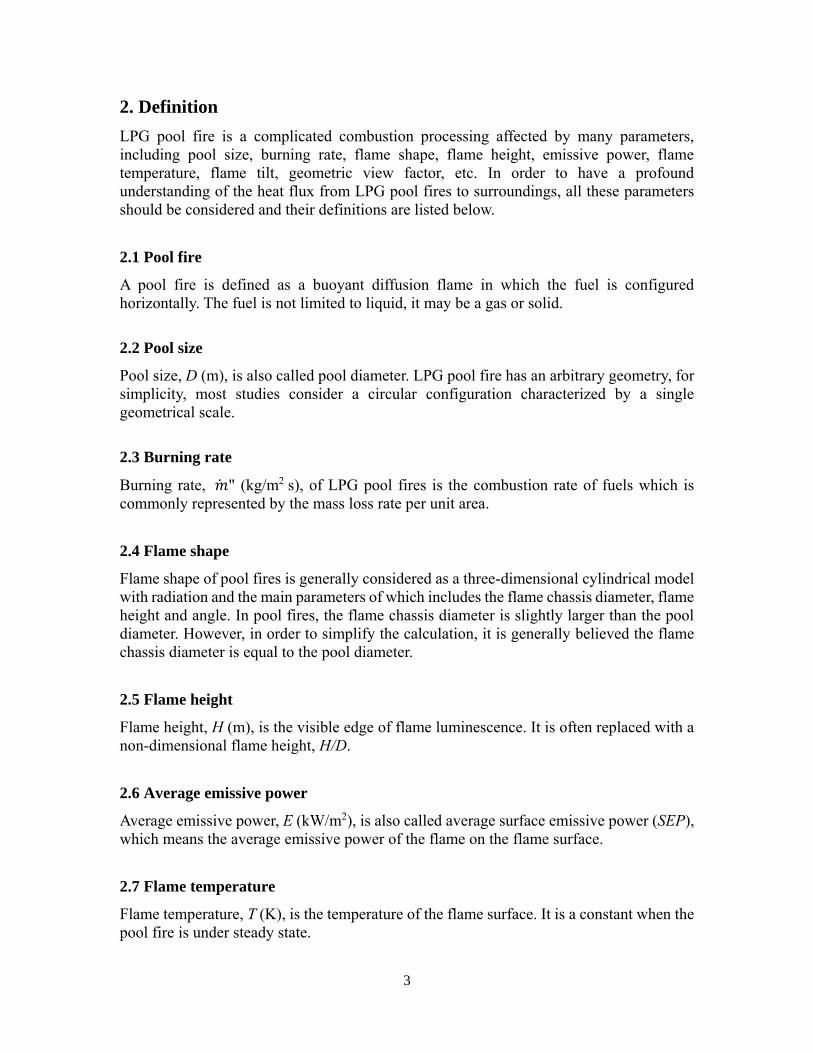
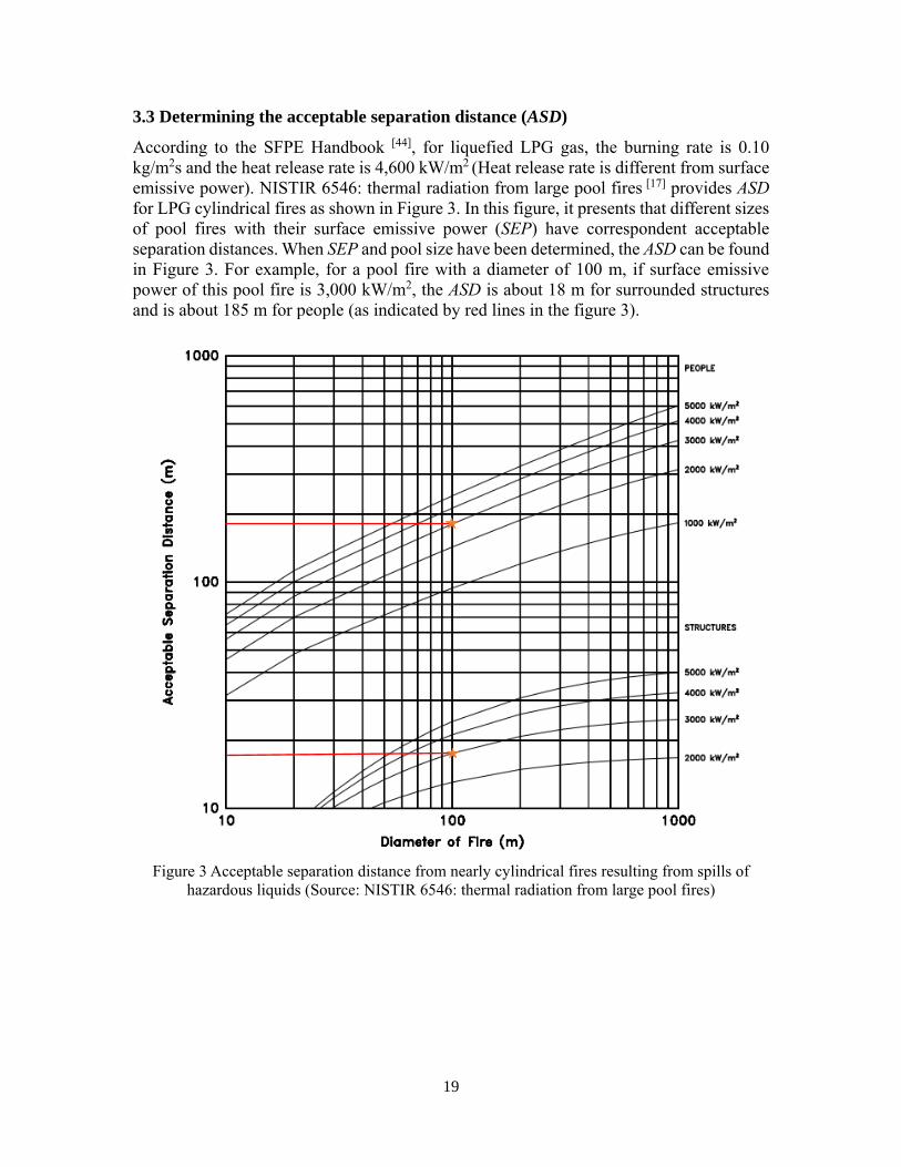
3.3 Determining the acceptable separation distance (ASD)
According to the SFPE Handbook [44], for liquefied LPG gas, the burning rate is 0.10
kg/m2s and the heat release rate is 4,600 kW/m2 (Heat release rate is different from surface
emissive power). NISTIR 6546: thermal radiation from large pool fires [17] provides ASD
for LPG cylindrical fires as shown in Figure 3. In this figure, it presents that different sizes
of pool fires with their surface emissive power (SEP) have correspondent acceptable
separation distances. When SEP and pool size have been determined, the ASD can be found
in Figure 3. For example, for a pool fire with a diameter of 100 m, if surface emissive
power of this pool fire is 3,000 kW/m2, the ASD is about 18 m for surrounded structures
and is about 185 m for people (as indicated by red lines in the figure 3).
Figure 3 Acceptable separation distance from nearly cylindrical fires resulting from spills of
hazardous liquids (Source: NISTIR 6546: thermal radiation from large pool fires)
20
4. Modelling of heat flux from pool fires to LPG containers
The literature for LPG containers’ failure caused by heat flux of LPG pool fires is extremely
limited, and all collected data just describe the situation that LPG containers are heated by
engulfing fires rather than by pool fires. However, there are two useful additional
references, “Impact of a distant wildland fire on an LPG tank” [45] and “An experimental
study of an LPG Tank at low filling level heated by a remote wall fire” [46] which can give
the committee some instructions to simulate the circumstance that tanks or containers are
heated by LPG pool fires.
Heymes, F. et al. [45] calculated the radiative heat flux from the wildland fire to the LPG
tank and carried out experiments that a 2,000 L pressure vessel with 15% full of liquefied
LPG heated by a remote fire with a natural burning system. The distance between the vessel
and the fire was 50 m with theoretically expected heat flux 24 kW/m2.
The experimental results show the average radiative heat flux was 26 kW/m2 and the
highest intensity came to 44 kW/m2 with corresponded wall temperature 427 ℃. If the
committee plans to carry out similar experiments in the future, the data of radiative heat
flux values from LPG pool fires to a LPG container can be obtained easily according the
methods in this paper.
Heymes, F. et al. [46] carried out another similar study which described tests that were
conducted with a 2,300 L cylindrical container filled with 15% full propane. Comparing to
the precious study [45], the authors added three different distances varying from 1.5 to 3.8
m between the fire and the heated tanks. Table 13 summaries the estimated results and
experimental data.
Table 13 Heat flux on tank surfaces and emissive powers of fires
Estimated
distance to the
fire (m)
Peak heat flux
range at tank
surface (kW/m2)
Average peak heat
flux range at tank
surface (kW/m2)
Estimated emissive
power of fires
(kW/m2)
Measured average
fire temperature
(℃)
3~3.8 15~42 26 68~81 750
2~2.8 8~41 24 48~55
1.5~2.3 32~58 43 77~84 830
21
5. Conclusion and future work
All collected experimental data are grouped by fuel and fire scale in this report,
respectively. For the LPG pool fire sizes from 0.1 m to 10 m, the average emissive power
is ranging from 35 kW/m2 to 79 kW/m2; for the size from 10 m to 20 m, the counterpart
power is ranging from 47 kW/m2 to 134 kW/m2. The heat flux at the distances of 40 m, 55
m, 60 m, 80 m and 260 m to the pool fire center has been measured clearly in related
literature. In order to broaden the database and compare with the main parameters of other
fuels’ pool fires for the committees, this report also contains a large amount of the
experimental data of pool fires for other 14 types of fuels.
However, as for the values of heat flux that may cause the LPG tank to potentially fail, a
large number of literature shows LPG tanks heated in engulfing fires. There is no data
showing the amount of heat flux of LPG pool fires that will lead the tanks to fail. The tank
sizes, the level of liquids inside the tanks, and the Pressure Release Valve (PRV) types
should also be considered. However, we may use models to calculate them. The literature
in Section 4 provides significant instructions to compute them and carry out related
experiments.
To provide more data to the committees, the final report also contains some classical
models to compute the significant parameters of LPG pool fires listed in Appendix A.
However, it is difficult to calculate the heat flux from LPG pool fires to LPG tanks or
containers in a limited time because of too many variables. We may utilize Large Eddy
Simulation (LES) and finite element method (FEM) which are acceptable methods to
simulate pool fires and calculate the heat flux in different distances with different pool
sizes.
22
6. References
1. NFPA, “NFPA 58: Liquefied Petroleum Gas Code”, National Fire Protection Association,
2014.
2. NFPA, “NFPA 59: Utility LP-Gas Plant Code”, National Fire Protection Association,
2015.
3. Muñoz, M., Arnaldos, J., Casal J., and Plana, E, “Analysis of geometric and radiative
characteristics of hydrocarbon pool fires,” Combustion and Flame, 139, 2004, pp. 263-277.
4. Fu, T. T., “Heat radiation from fires of aviation fuels,” Fire Technology, 10(1), 1974, pp.
54-67.
5. Dayan, A., and Tien, C. L., “Radiant heating from a cylindrical fire column,” Combustion
Science and Technology, 9(1), 1974, pp. 41-47.
6. May, W. G., and McQueen, W., “Radiation from large liquefied natural gas fires,”
Combustion Science and Technology, 7(2), 1973, pp. 51-56.
7. Yumoto, T., "An experimental study on heat radiation from oil tank fire," FRI Research
Report, No. 33, 1971, pp. 23.
8. Koseki, H., and Yumoto, T., “Air entrainment and thermal radiation from heptane pool
fires”, Fire Technology, 24(1), 1988, pp. 33.
9. Mudan, K.S., “Thermal radiation hazards from hydrocarbon pool fires,” Progress in
Energy and Combustion Science, 10(1), 1984, pp. 59-80.
10. Uehara, Y., Yumoto, T., and Nakagawa, S., “Burning characteristics of cryogenic fuels,”
FRI Research Report, No. 37, 1973, pp. 1.
11. Minzer, G. A., and Lyre, J. A., “Large scale LNG and LPG pool fires,” European
Federation of Chemical Engineering Publication Series, 71, 1982, pp.147-163.
12. Hagglund, B., and Persson, L., “The heat radiation from petroleum fires,” FOA Report,
Försvarets forskningsanstalt, Stockholm, 1976.
13. Raj, P. P. K., Moussa, A. N., and Aravamudan, K., “Experiments involving pool and vapor
fires from spills of LNG on water,” National Technical Information Service, Report No.
USCG-D-55-79, 1979.
14. Modak, A., “Radiation from products of combustion,” Fire Safety Journal, 1(6), 1979, pp.
339-361.
15. Mizner, G. A., and Eyre, J. A., “Radiation from liquefied fire on water,” Combustion
Science and Technology, 35, 1983, pp. 33-57.
16. Mudan, K. S., “Hydrocarbon pool and vapor fire data analysis,” U.S. Department of
Energy, USDOE Report DE-AC01-83EP16008, 1984.
17. McGrattan, K.B., Baum, H.R., and Hamins, A., “NISTIR 6546: thermal radiation from
large pool fires,” National Institute of Standards & Technology, 2000.
18. Koseki, H., “Combustion properties of large liquid pool fires,” Fire Technology, 25, 1989,
pp. 241-255.
19. Yamaguchi, T., and Wakasa, K., “Oil pool fire experiment,” First International Symposium
on Fire Safety Science, 1986, pp. 911-918.
20. Seeger, P.G., “On the Combustion and heat transfer in fires of liquid fuels in tanks,” Heat
Transfer in Fires, Section 2, Chapter 3, 1974, pp. 95-126.
21. Yumoto, T. J., "Fire spread between two oil tanks," Journal of Fire Flammable, 8, 1977,
pp. 494-505.
22. May, W., and McQueen, W. G., “Radiation from large liquefied natural gas fires,”
Combustion Science and Technology, 7, 1973, pp. 51-56.
23. Fan, C. G., Ji, J., Li, Y. Z., Ingason, H., and Sun J. H., “Experimental study of sidewall
effect on flame characteristics of heptane pool fires with different aspect ratios and
orientations in a channel,” Proceedings of the Combustion Institute, 6(196), 2016, pp. 1-9.
23
24. May, H.G., and McQueen, W., “Radiation from large liquefied natural gas fires,”
Combustion Science and Technology, 7, 1973, pp. 51-66.
25. American Gas Association, “LNG safety program, Interim report on phase ii work,”
Bsyyrllr V Columbus Laboratories, IS-3-1, 1974.
26. Raj, P.K., and Atallah, S., “Thermal radiation from LNG fires,” Advances in Cryogenic
Engineering, 20, 1974, pp. 143-150.
27. Japanese Gas Association, “A study of dispersion of evaporated gas and ignition of LNG
pool resulting from continuous spillage of LNG,” Journal of Japanese Gas Association,
1976.
28. Mizner, G.A., and Eyre, J.A., “Large scale LNG and LPG pool fires,” European Federation
of Chemical Engineering, 1982.
29. Nedelka, D.J., Moorhouse, J., and Tucker, R.F., “The monitor 35 m diameter LNG pool
fire experiments,” 9th International Conference on Liquefied Natural Gas, 1989.
30. Raj, P. K., “Large LNG fire thermal radiation-modeling issues & hazard criteria revisited,”
Process Safety Progress, 24(3), 2005, pp. 192-202.
31. Raj, P. K., “LNG fires: A review of experimental results, models and hazard prediction
challenges,” Journal of Hazardous Materials, 140, 2007, pp. 444-464.
32. Raj, P. K., Moussa, A. N., and Aravamudan, K, “Experiments involving pool and vapor
fires from spills of LNG on water,” U.S. Department of Transportation, USCG Report No.
CG-D-55-79, 1979.
33. Shebeko, Y. N., Bolodian, I.A., Filippov, V.N., Navzenya, V.Y., Kostyuhin, A.K.,
Tokarev, P.M., and Zamishevski, E.D., “A study of the behavior of a protected vessel
containing LPG during pool fire engulfment,” Journal of Hazardous Materials, 77, 2000,
pp. 43-56.
34. Shebeko, Y. N., Smolin, I.M., Korolchenko, A.Y., Shevchuk A.P., Borodkin, A.N.,
Malkin, V.L., Simonov, O.A., Gurinovich, L.V., Popov, S.A., Kolosov, V.A., and
Smirnov., E.V., “Some aspects of fire and explosion hazards of large LPG storage vessels,”
Journal of Loss Prevention in the Process Industries, 8(3), 1995, pp. 163-168.
35. Palazzi, E., and Fabiano, B., “Analytical modelling of hydrocarbon pool fires:
Conservative evaluation of flame temperature and thermal power,” Process Safety and
Environmental Protection, 90, 2012, pp. 121-128.
36. Crawley, F.K., “The assessment of major hazards: the effects of the ignition of a major fuel
spillage,” The Institution of Chemical Engineers Symposium Series, 71, 1982, pp. 125-145.
37. Brown, L.E., Wesson, H.R., and Walker, J.R., “Thermal radiation from LNG fire
suppression,” Processing Conference on Natural Gas Resources and Technologies, 1974.
38. Hiroshi K., “Large scale pool fires: results of recent experiments,” Fire Safety Science-
Proceedings of 6th International Symposium, 2000, pp. 115-132.
39. Birk, A.M., “On the response of 500-gal propane tanks to a 25% engulfing fire,” Journal
of Loss Prevention in the Process Industries, 19(6), 2006, pp. 527-541.
40. Droste, B., and Schoen, W., “Full scale fire tests with unprotected and thermal insulated
LPG storage tanks,” Journal of Hazardous Materials, 20, 1988, pp. 41-53.
41. Birk, A.M., “Analysis of a propane sphere BLEVE,” Chemical Engineering Transactions,
31, 2013, pp. 481-486.
42. Balke, C., Heller, W., Konersmann, R., and Ludwig, J. “Study of the failure limits of a tank
car filled with liquefied petroleum gas subjected to an open pool fire test,” Federal Institute
for Materials Research and Testing, 1999.
43. Moodie, K., “Fire engulfment tests on a 5 tone LPG tank,” Journal of Hazardous Materials,
20, 1988, pp. 55-71.
44. Babrauskas, V., “SFPE Handbook: burning rates,” National Fire Protection Association,
2nd edition, 1995.
24
45. Heymes, F., Aprin, L., Birk, A.M., Slangen, P., Jarry J.B., François, H., and Dusserre, G.,
“An Experimental study of an LPG tank at low filling level heated by a remote wall fire”,
Journal of Loss Prevention in the Process Industries, 26, 2013, pp. 1481-1491.
46. Heymes, F., Aprin, L., Birk, A.M., Slangen, P., Jarry J.B., François, H., and Dusserre, G.,
“Impact of a distant wildland fire on a LPG tank”, Fire Safety Journal, 61, 2013, pp. 100-
107.
25
Appendix A: Models for Calculating Parameters of LPG Pool
Fires Nomenclature:
�̇�: burning velocity of a finite diameter pool
(m/s)
�̇�𝑚𝑎𝑥: burning velocity of an infinite
dimension pool (m/s)
�̇�: heat transfer from flame to liquid pool (W)
𝑇𝐹: flame temperature (K)
𝑇𝑎: ambient temperature (K)
F: geometric view factor
d: fire diameter (m)
K: conduction heat transfer coefficient (W/m
K)
H: convective heat transfer coefficient (W/m2
K)
𝜅 extinction coefficient (m-1)
𝜎: Stefan-Boltzman Constant (W/m2 K4)
𝑛𝑖, 𝑚𝑖: mole-fraction composition in the
vapor and liquid phases, respectively
𝑇𝑖 and 𝑇𝑏: initial and boiling temperatures,
respectively, (K)
𝐶𝑝: specific heat capacity (J/kg K)
Δ𝐻𝑐 and Δ𝐻𝑣: the net heat of combustion and
the heat of vaporization (in J/kg) at the
boiling point of the liquid fuel, respectively
�̇�": mass burning rate (kg/m2 s)
D: steady state diameter of the pool (m)
dm and tm: maximum diameter and the time to
reach the maximum diameter (m), (s)
g: acceleration due to gravity (m/s2)
u*: the non-dimensional wind velocity
𝜌𝑎: ambient air density, kg/m3
𝜔: inverse volumetric expansion ratio due to
combustion
𝑢10∗ : the non-dimensional wind
𝑢𝑤: wind speed (m/s)
𝑣: kinematic viscosity of air (m2/s)
�̇�: total energy radiated per unit time (W)
�̇�: fuel mass burning rate (kg/s)
𝜂: fraction of combustion energy radiated
X: radial distance from source to the observer
(m)
E: the constant emissive power of the flame
in kW/m2
Ea: average emissive power at flame surface
(kW/m2)
𝜏: atmospheric transmissivity
F: geometric view factor
𝐸𝑏 :black body emissive power (kW/m2)
𝜀: emissivity
𝑇𝑓: radiation temperature of the flame (K)
T: ambient temperature (K)
𝜀𝑠: spectrally averaged emissivity of soot
𝜀𝑐 𝑎𝑛𝑑 𝜀𝑤: molecular band integrated
emissivity of CO2 and H2O
∆𝜀𝑐,𝑤: correction factor for the CO2-H2O
band overlap
C: effective soot concentration parameter
L: path length (m)
C2: Plank's second constant
𝜓(3): Penta gamma function
𝑘𝑚: extinction coefficient (m-1)
h: flame height or length/flame radius
S: distance to observer from axis/flame
radius
𝛽: angle of inclination of the observer to the
horizontal
𝜙: sin-1 1/S
𝜏𝑠: 𝑡𝑟𝑎𝑛𝑠𝑚𝑖𝑠𝑠𝑖𝑣𝑖𝑡𝑦 𝑜𝑓 𝑠𝑚𝑜𝑘 = 𝑒−(𝑘𝑚𝐶𝑠𝐿𝑏)
𝑘𝑚: specific soot extinction area (m2/kg)
𝐶𝑠: mass concentration of smoke in flame
gases (kg/m3)
𝐿𝑏: beam length, which can be equal to
0.63D for cylindrical fires (m)
𝜒𝑟: fraction of combustion energy released
that is radiated, is equal to η as mentioned
earlier.
26
In general, thermal radiation hazards from LPG poor fires depend on a large number of
parameters, including the size and shape of the fire, the duration of the fire, the distance to
the object, and the characteristics of the object exposed to the thermal radiation. When
evaluating the thermal radiation field surrounding a fire, burning rate of the pool fire, flame
height, and flame tilt have been considered. In developing siting criteria, such as spacing
between storage tanks or containers, there are two basic types of thermal radiation models
available: point source model and solid flame radiation model, which can be applied for
computing the thermal radiation. The references [Mudan, K., Thermal radiation hazards
from hydrocarbon pool fires. Progress in Energy and Combustion Science, 10(1), 1984,
59-80; Raj, P. K., Large LNG fire thermal radiation-modeling issues and hazard criteria
revisited. Process Safety Progress, 24(3), 2005, 192-202; and Muñoz, M, et al. E., Analysis
of the geometric and radiative characteristics of hydrocarbon pool fires. Combustion and
Flame, 139(3), 2004, 263-277.] made some conclusions about how to calculate these
parameters of pool fires listed below.
1. Burning rate
Figure1 Burning rates for various hydrocarbon pool fires
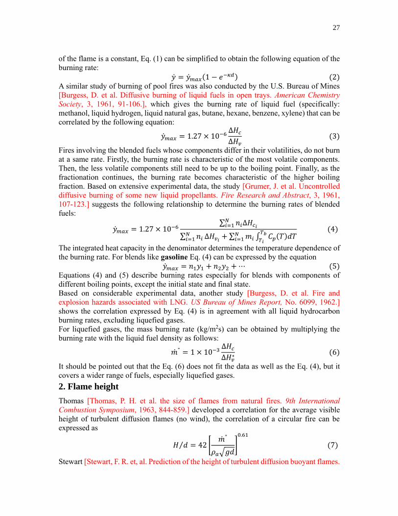
Figure 1 shows Hottel’s research [Hottel, H. C. Certain laws governing diffusive burning
of liquids. Fire Research Abstracts and Reviews, 1, 1959, 41-44] that the relationship
between burning velocity and pool diameter can be used for all types of fuels. He also
demonstrated that these behaviors can be related to the heat transfer rate determining the
vaporization rate of the fuel. The heat transfer from the fire to the liquid pool can be
expressed by �̇�
(𝜋𝑑2
4)
=4𝐾
𝑑(𝑇𝐹 − 𝑇𝑎) + 𝐻(𝑇𝐹 − 𝑇𝑎) + 𝜎𝐹(𝑇𝐹
4 − 𝑇𝑎4)(1 − 𝑒−𝜅𝑑) (1)
where the left term represents the mean heat flux to the liquid pool from the fire; the first
right term represents the conductive heat transfer rate through the pan (liquid pool) rim;
the second term shows the convective heat flux and the last term shows the radiative
transfer rate.
The average heat flux to the pool divided by the heat of vaporization of the liquid gives the
liquid burning rate (𝑦)̇. The conduction term in Eq. (1) is an edge effect only for fires with
extremely small dimensions importantly. For pool size larger than about 1 m, the radiative
term in Eq. (1) dominates the heat flux to the pool. If we assume that geometric view factor
27
of the flame is a constant, Eq. (1) can be simplified to obtain the following equation of the
burning rate:
�̇� = �̇�𝑚𝑎𝑥(1 − 𝑒−𝜅𝑑) (2)
A similar study of burning of pool fires was also conducted by the U.S. Bureau of Mines
[Burgess, D. et al. Diffusive burning of liquid fuels in open trays. American Chemistry
Society, 3, 1961, 91-106.], which gives the burning rate of liquid fuel (specifically:
methanol, liquid hydrogen, liquid natural gas, butane, hexane, benzene, xylene) that can be
correlated by the following equation:
�̇�𝑚𝑎𝑥 = 1.27 × 10⁻⁶Δ𝐻𝑐
Δ𝐻𝑣 (3)
Fires involving the blended fuels whose components differ in their volatilities, do not burn
at a same rate. Firstly, the burning rate is characteristic of the most volatile components.
Then, the less volatile components still need to be up to the boiling point. Finally, as the
fractionation continues, the burning rate becomes characteristic of the higher boiling
fraction. Based on extensive experimental data, the study [Grumer, J. et al. Uncontrolled
diffusive burning of some new liquid propellants. Fire Research and Abstract, 3, 1961,
107-123.] suggests the following relationship to determine the burning rates of blended
fuels:
�̇�𝑚𝑎𝑥 = 1.27 × 10⁻⁶∑ 𝑛𝑖∆𝐻𝑐𝑖
𝑁𝑖=1
∑ 𝑛𝑖𝑁𝑖=1 ∆𝐻𝑣𝑖
+ ∑ 𝑚𝑖 ∫ 𝐶𝑝(𝑇)𝑑𝑇𝑇𝑏
𝑇𝑖
𝑁𝑖=1
(4)
The integrated heat capacity in the denominator determines the temperature dependence of
the burning rate. For blends like gasoline Eq. (4) can be expressed by the equation
�̇�𝑚𝑎𝑥 = 𝑛1𝑦1 + 𝑛2𝑦2 + ⋯ (5) Equations (4) and (5) describe burning rates especially for blends with components of
different boiling points, except the initial state and final state.
Based on considerable experimental data, another study [Burgess, D. et al. Fire and
explosion hazards associated with LNG. US Bureau of Mines Report, No. 6099, 1962.]
shows the correlation expressed by Eq. (4) is in agreement with all liquid hydrocarbon
burning rates, excluding liquefied gases.
For liquefied gases, the mass burning rate (kg/m2s) can be obtained by multiplying the
burning rate with the liquid fuel density as follows:
�̇�" = 1 × 10⁻³∆𝐻𝑐
∆𝐻𝑣∗
(6)
It should be pointed out that the Eq. (6) does not fit the data as well as the Eq. (4), but it
covers a wider range of fuels, especially liquefied gases.
2. Flame height
Thomas [Thomas, P. H. et al. the size of flames from natural fires. 9th International
Combustion Symposium, 1963, 844-859.] developed a correlation for the average visible
height of turbulent diffusion flames (no wind), the correlation of a circular fire can be
expressed as
𝐻 𝑑⁄ = 42 [�̇�"
𝜌𝑎√𝑔𝑑]
0.61
(7)
Stewart [Stewart, F. R. et, al. Prediction of the height of turbulent diffusion buoyant flames.
28
Combustion Science Technology, 2, 1970, 205-212.] also developed a similar correlation
which has considered the fuel’s properties as follows:
𝐻 𝑑⁄ = 14.73 [𝜔(𝑟+
𝜔
𝜌0′ )
(1−𝜔)5 ] [�̇�"
𝜌𝑎√𝑔𝑑]
0.4
(8)
The presence of wind may also alter the visible length of flames. The correlation developed
by Thomas [Thomas, P. H. et al. the size of flames from natural fires. 9th International
Combustion Symposium, 1963, 844-859.] based on wood crib fires is as follows:
𝐻 𝑑⁄ = 55[�̇�"/𝜌𝑎√𝑔𝑑]0.67
[𝑢∗]−0.21 (9)
𝑢∗ =𝑢𝑤
[𝑔�̇�"𝑑
𝜌𝑣]
13
(10)
Moorhouse [Moorhouse, J. et al. Scaling criteria for pool fires derived from large scale
experiments. International Symposium Series, No. 71, 1982, 165-179.] carried out
considerable large scale experiments of LNG and LPG pool fires. The crosswind and
downwind were considered and analyzed to determine the flame height (length). Therefore,
the correlation can be as follows:
𝐻 𝑑⁄ = 6.2[�̇�"/𝜌𝑎√𝑔𝑑]0.254
[𝑢10∗ ]−0.044 (11)
where 𝑢10∗ is the nondimensional wind speed determined using Eq. (9) with measured wind
speed at a height of 10m. In both Eq. (8) and (9), u* is assigned a value of unity if it is less
than one.
3. Flame tilt
The correlations relating the tilt angle θ of the flame from the vertical to wind velocity are
listed below. If there is no wind in LPG pool fires of this project, this section can be
negligible. The correlation given by Welker [Welker, J. R. et al. Bending of wind-blown
flames from liquid pools. Fire Technology, 2(2), 1966, 127-135.] was derived from small
size tests (0.3-0.6 m) with liquid fuels and is as follows:
tan 𝜃
cos 𝜃= 3.3 [
𝑑𝑢𝑤
𝑣]
0.07
[𝑢𝑤
2
𝑔𝑑]
0.8
(𝜌𝑟
𝜌𝑎)
−0.6
(12)
Thomas [Thomas, P. H. et al. The size of flames from natural fires. 9th International
Combustion Symposium, 1963, 844-859.] gave another correlation for flame tilt listed
below
cos 𝜃 = 0.7 [𝑢𝑤
(𝑔�̇�"/𝜌𝑎)1/3]
−0.49
(13)
Based on measured values, the A.G.A. [A.G.A., LNG safety research program. American
Gas Association Report, IS 3-1, 1974.] proposed the following correlation to determine the
flame tilt:
cos 𝜃 = {
1 𝑓𝑜𝑟 𝑢∗ < 11
√𝑢∗ 𝑓𝑜𝑟 𝑢∗ ≥ 1
(14)
where u* is the non-dimensional wind velocity given by Eq. (10) with a wind velocity
measured at a flame height of 1.6 m. Although there is considerable scatter in the measured
flame tilt, the correlation by Eq. (14) is more accurate than correlation by Eq. (13).
29
4. Thermal radiation form pool fires
4.1 Point source model
The point source thermal radiation model is based on the following assumptions: (1) the
flame can be represented as a small source of thermal energy; (2) the energy radiated from
the flame is a specified fraction of energy released during combustion; (3) the thermal
radiation intensity varies proportionally with the inverse square of the distance from the
source.
The radiant intensity at any distance from the source is given by the following equations:
�̇�" =�̇�
4𝜋𝑥2 (15)
and
�̇� = 𝜂�̇�Δ𝐻𝑐 (16)
While the above model is acceptable widely because of its simplicity, while there are two
important limitations which should be recognized clearly.
The first one involves the modeling of radiative output and another one is the description
of the diversity intensity as a function of distance from the fire source. Moorhouse
[Moorhouse, J. et al. Thermal radiation hazards from large pool fires and fireballs.
International Chemical Engineering Symposium Series, No.71, 1982, 387-428.] concluded
that the fraction of combustion energy radiated expressed as follows:
𝜂 =𝐸
�̇�"Δ𝐻𝑐
[1 + 4𝐻/𝑑] (17)
In large scale hydrocarbon pool fires, smoke obscuration contributes to a reduction in
measured flame emissive powers.
The second limitation is that the point source model overestimates the intensity of heat flux
(thermal radiation) at observer locations close to the fire because of the nearfield radiation
influenced by flame size, shape, tilt and the relative orientation greatly.
In conclusion, the point source model provides a simple method to evaluate the intensity
of thermal radiation at far field where the effects of flame geometry are not significant.
This model can be used to determine thermal radiation hazards to personnel. It must be
pointed out that caution must be exercised in using this model to solely determine siting
criteria, such as spacing between two storage tanks or containers.
4.2 Solid flame radiation model
Solid flame radiation model assumes that the entire visible part of the flame emits heat flux
and the non-visible volume of the flame contributes slightly, which means that the rate of
energy emission is only from the visible fire flame. Studies by Markstein [Markstein, G.
H. et al. Radiative energy transfer from turbulent diffusion flames. Combustion and Flame,
27, 1976, 51-63.] have confirmed that the irradiance of the gas plume above the pool fire
contributes less than 10% of the mean irradiance of the visible flame. Therefore, it is in
wide use for describing heat flux from LPG pool fires.
The solid flame model proposes the flame to be a cylindrical model with diameter equal to
the base diameter of the fire and axle length equal to the visible flame height. The flame is
also assumed to radiate uniformly over the entire surface of the cylinder although it is
possible to introduce a radiation distribution along the flame length. The thermal radiation
30
intensity to an element outside the flame envelope is given by the following equation:
�̇�" = 𝐸𝑎𝐹𝜏 (18)
Where the emissive power Ea is difficult to determine. Modak [Modak, A. T. et al.
Radiation from products of combustion. Fire Safety Journal, 1(6), 1979, 339-361.] has
developed simplified calculations for obtaining the gas emissivity. Markstein [Markstein,
G. H. et al. Scaling of radiative characteristics of turbulent diffusion flames. 17th
International Symposium on Combustion, 16(1), 1977, 1407-1419.] has proposed a model
which considers a fire as a two-species emitter whose total radiance is equal to the weighted
sum of the radiance due to gas emissions and luminous soot. The surface emissive power
of turbulent fires may be expressed approximately:
𝐸𝑎 = 𝐸𝑏𝜀 (19)
The emissive power of cylindrical model is given by Plank's law of radiation with
temperature:
𝐸𝑏 = 𝜎[𝑇𝑓4 − 𝑇𝑎
4] (20)
It is extreme different to calculate the combination emissivity of the burnt gases, like soot,
water vapor and carbon dioxide, even when the concentrations of these gases are uniform
and the temperature is considered constant. However, the combined emissivity can also be
expressed by:
𝜀 = 𝜀𝑠 + 𝜀𝑐 + 𝜀𝑤 − ∆𝜀𝑐,𝑤 (21)
Modak [Modak, A. T. et al. Radiation from products of combustion. Fire Safety Journal,
1(6), 1979, 339-361.] has shown the results from the research of Felske [Felske, J. D. et al.
Calculation of emissivity of luminous flames. Combustion Science Technology. 7, 1973,
25-31.] and other test results that the soot emissivity can be determined as followed:
𝜀𝑠 = 1 −15
𝜋4𝜓(3) [1 +
7
𝐶2𝑇𝑓𝐶𝐿] (22)
Yuen [Yuen, W. W. et al. Simple calculation scheme for the luminous flame emissivity.
17th International Symposium on Combustion, 1977, 1481-1487.] reviewed many
experimental results on soot emission from luminous flames of gaseous, polymer and wood
fuels and then confirmed that Eq. (22) can be expressed:
𝜀𝑠 = 1 − 𝑒−𝜅𝑠𝐿 (23)
Where
𝜅𝑠 = 3.6𝐶𝑇𝑓
𝐶2 (24)
𝜀𝑐, 𝜀𝑤 and Δ𝜀𝑐,𝑤 can be calculated by the charts form handbook by Hottel [Hottel, H. C. et
al. Radiative Transfer. McGraw Hill, New York, 1967.].
In general, the emissivity of a homogeneous mixture of path-length 𝑥 is given by:
𝜀𝑚(𝑥) =1
𝜎𝑇𝑓4 ∫ 𝐸𝑏(𝜆)[1 − exp (−𝑘𝑚𝜆𝑥)]
∞
0𝑑𝜆 (25)
If the mixture is spectrally gray, 𝑘𝑚=𝑘𝑚𝜆 and the integral becomes
𝜀𝑚(𝑥) = 𝜀 = 1 − 𝑒𝑥𝑝[−𝑘𝑚𝑥] (26)
Although the heat flux from black soot is relative low, hot spots have a higher surface
emissive power due to the turbulent mixing. Large eddies within the flame bring fuel to the
outer edges of the fire plume and a more efficient combustion takes place on the flame
surface. Based on a qualitative observation of the video records of kerosene fires on land
[NASA, On the experiments with 7.5 m and 15 m JP-4 fuel pool fire measurements.
National Aeronautical and Space Administration, 1979.] and gasoline fires on water, the
31
results show that the luminous zones cover approximately 20% of the flame surface area,
on a time averaged basis. These luminous spots have an emissive power of about 110~130
kW/m2. However, it is not possible to calculate the radiation field surrounding a fire with
intermittent luminous spots. Hagglund [Hagglund, B. et al. The Heat radiation from
petroleum fires. FOA Report C, 20126-D6(A3), 1976.] observed that the emissive power
of the black smoke is about 20 kW/m2 and the temperature is about 800 K.
For example, if we assume that 80% of the surface area is covered with black smoke and
20% with luminous spots, the time average emissive power is given by the following
expression:
𝐸𝑎𝑣 = 0.2 ∗ 130 + 0.8 ∗ 20 = 42𝑘𝑊/𝑚2 (27)
5. Geometric view factor
In general, the view factor is represented by the following equation:
𝐸𝐴1→𝑑𝐴2= ∮
cos 𝜃1cos 𝜃2
𝑟2𝐴1𝑑𝐴1 (28)
Where 𝜃1 and 𝜃2 are the angles made by the normal, respectively, and d𝐴 on the fire and
𝑑𝐴2 on the receiving element; r is the distance between the fire element and the receiving
element.
In the point source model, the view factor is given by:
𝐹𝑃~𝑅2/𝑥2 (29)
where R is the radius of the source and x is the distance from the center of the fire to
observer location. It has been pointed out earlier that point source models are applicable to
predicting heat flux in long distances from the fire.
In the solid flame model, the turbulent flame is considered as a cylinder. Under wind free
conditions, the cylinder is vertical. Under the influence of wind, the cylinder is assumed to
be tilted. The horizontal and vertical view factors for a vertical cylinder are as follows:
𝐹𝐻 = 1
𝜋[
(𝐵−1 𝑆⁄ )
√𝐵2−1tan−1 √
(𝐵+1)(𝑆−1)
(𝐵−1)(𝑆+1)−
(𝐴−1 𝑆)⁄
√𝐴2−1tan−1 √
(𝐴+1)(𝑆−1)
(𝐴−1)(𝑆+1)] (30)
𝐹𝑉 =1
𝜋[
1
𝑆tan−1 ℎ
√𝑆2−1+
ℎ
𝑆{tan−1 √
𝑆−1
𝑆+1−
𝐴
√𝐴2−1tan−1 √
(𝐴+1)(𝑆−1)
(𝐴−1)(𝑆+1)}] (31)
Here,
h = flame height or length/flame radius, S = distance to observer from axis/flame radius,
𝐴 =ℎ2+𝑆2+1
2𝑆 , and 𝐵 =
1+𝑆2
2𝑆.
The maximum view factor is the vectorially sum of horizontal and vertical view factors
and is as follows:
𝐹𝑚 = √𝐹𝐻 2 + 𝐹𝑉
2 (32)
Rein [Rein, R. G., Radiation view factors for titled cylinders. Journal of Fire and
Flammability, 1, 1970, 140-153.] calculated the radiation view factors for tilted cylinders.
In their calculations, they replaced the view factor integral by a summation and numerically
evaluated the view factor by dividing the cylinder into several incremental rectangular
areas. Raj [Raj, P. K. et al., Assessment models in support of the hazard assessment
handbook (Chapter 9). Technical Report Prepared for the U.S., No. AD776617, 1974.]
employed an analytical method to determine the view factors for tilted cylinders. The view
32
factor for a tilted cylinder with a circular base is in following equation:
𝐹 =1
𝜋[(cos 𝛽 sin 𝜃 − sin 𝛽 cos 𝜃 )(𝐴1 cos 𝜙 + ℎ𝐴2) + cos 𝛽 (𝐴3 − 𝐴4)] (33)
Where 𝛽 = angle of inclination of the observer to the horizontal, 𝜙 = sin-1 1/S, and h and S
are defined earlier.
The other parameters appearing in Eq. (33) are as follows:
𝐴1 =1
𝐵1[tan−1 [
ℎ − (𝑆 − 1 𝑆⁄ ) sin 𝜃
𝐵1] + tan−1 [
(𝑆 − 1 𝑆⁄ ) sin 𝜃
𝐵1]]
𝐵1 = {(𝑆2 − 1) cos2 𝜃 + (1 − 1 𝑆2⁄ ) sin2 𝜃}1 2⁄
𝐴2 = ∫sin 𝑣𝑑𝑣
[(1+ℎ2+𝑆2−2𝑆ℎ sin 𝜃)+2(ℎ sin 𝜃−𝑆) sin 𝑣]
𝜋 2⁄
𝑣=0 (34)
𝐴3 = ∫(𝑆 sin 𝑣 − 1)𝑑𝑣
[1 + 𝑆2 − 2𝑆 sin 𝑣]
𝜋 2⁄
𝑣=0
𝐴4 = ∫(𝑆 sin 𝑣 − 1)𝑑𝑣
[(1 + ℎ2 + 𝑆2 − 2𝑆ℎ sin 𝜃) + 2(ℎ sin 𝜃 − 𝑆) sin 𝑣]
𝜋 2⁄
𝑣=0
The above integrals are evaluated to determine the view factor, and the observer
orientation, 𝛽, is increased from 0̊ to a maximum of 180̊ to determine the maximum view
factor.
6. Smoke effects on radiation
Raj [Raj, P. J. et al. Large LNG fire thermal radiation modeling issues & hazard criteria
revisited. Process Safety Progress, 24(3), 2005, 192-202.] presents that smoke in a fire
would absorb thermal radiation emission and reduce the effective emissive power, in this
situation, the effective emissive power can be expressed by
𝐸𝑒 = 𝐸𝜏𝑠 (35)
7. Radiation to surroundings (Fractional energy radiated by a fire)
According to perspective of Raj [Raj, P. J. et al. Large LNG fire thermal radiation modeling
issues & hazard criteria revisited. Process Safety Progress, 24(3), 2005, 192-202.], The
heat flux to an object at a distance S from the center of a pool fire of diameter D can be
calculated by the equation
𝑞𝑓 = 𝜒𝑟
𝜋4
𝐷2�̇�"Δ𝐻𝑐
4𝜋𝑆2 (36)
For LNG fires of diameters less than 15 m, 𝜒𝑟 is varying between 0.12 and 0.32, while for
larger diameter pool fires with effects of smoke obscuration effects, especially for heavier
hydrocarbon fuels (other than LNG), like LPG, there is a correlation [McGrattan, K.B,
H.R. et al., Thermal radiation from large pool fires. NISTIR 6546, National Institute of
Standards & Technology, U.S. Department of Commerce, 2000.] for the fraction radiated
with fire diameter represented by
33
𝜒𝑟 = 0.35𝑒−(𝐷20
) (37)
Where it should be noticed that this equation has not be unsubstantiated.

![Cyclohexane Phenol Binary Liquid Mixture: Behavior and ...binary mixtures are nitrobenzene - n-hexane, methanol – cyclohexane, and benzene - coconut oil [4]. 1.2. Literature Review](https://img.pdfslide.net/doc/110x75/5e674dcdceb16615607b8006/cyclohexane-phenol-binary-liquid-mixture-behavior-and-binary-mixtures-are-nitrobenzene.jpg)