Embed Size (px)
Citation preview
PNNL-21546
Prepared for the U.S. Department of Energy under Contract DE-AC05-76RL01830
Evaluation of Manual Ultrasonic Examinations Applied to Detect Flaws in Primary System Dissimilar Metal Welds at North Anna Power Station MT Anderson AA Diaz SR Doctor June 2012
PNNL-21546
Evaluation of Manual Ultrasonic Examinations Applied to Detect Flaws in Primary System Dissimilar Metal Welds at North Anna Power Station
MT Anderson
AA Diaz
SR Doctor
June 2012
Prepared for
the U.S. Department of Energy
under Contract DE-AC05-76RL01830
Pacific Northwest National Laboratory
Richland, Washington 99352

iii
Acronyms and Abbreviations
CAD computer-aided drafting
DMW dissimilar metal weld
EPRI Electric Power Research Institute
HiP hot iso-statically pressed
ID inside diameter
ISI inservice inspection
NRC U.S. Nuclear Regulatory Commission
OD outside diameter
PA phased array
PDI Performance Demonstration Initiative
PNNL Pacific Northwest National Laboratory
PWSCC primary water stress corrosion cracks
SNR signal-to-noise ratio
TJ technical justification
UT ultrasonic testing

v
Contents
Acronyms and Abbreviations ...................................................................................................................... iii
1.0 Background ........................................................................................................................................... 1
2.0 Objective ............................................................................................................................................... 1
3.0 Modeling of Manual UT Probe............................................................................................................. 2
4.0 Observations from North Anna Site Visit ............................................................................................ 5
4.1 Mock-up DM-05 .......................................................................................................................... 6
4.2 Mock-up DM-10 .......................................................................................................................... 7
5.0 Assessment of EPRI Technical Justification ........................................................................................ 8
6.0 Conclusions ........................................................................................................................................ 11
7.0 References .......................................................................................................................................... 12
Appendix A – Description of North Anna Mock-ups ............................................................................... A.1
Appendix B – A-scans on North Anna Mock-ups .....................................................................................B.1
vi
Figures
1 Profile of the North Anna Steam Generator DMW .............................................................................. 2
2 Tandem Probe Setup on DMW Specimen ............................................................................................ 4
3 Sound Field Simulations and −6 dB Filter ............................................................................................ 4
4 Simulated Sound Field at ID with a −12 dB Filter ............................................................................... 5
5 North Anna DMW Mock-up ................................................................................................................. 6
6 Mid-wall Fabrication Flaws or Implantation Artifacts Detected in North Anna Mock-ups (as
indicated by arrow) ............................................................................................................................... 7
Tables
1 Tandem Probe Description ................................................................................................................... 3
1
1.0 Background
During a recent inservice inspection (ISI) of a dissimilar metal weld (DMW) in an inlet (hot leg)
steam generator nozzle at North Anna Power Station Unit 1, several axially oriented flaws went
undetected by the licensee’s manual ultrasonic testing (UT) technique. The flaws were subsequently
detected as a result of outside diameter (OD) surface machining in preparation for a full structural weld
overlay. The machining operation uncovered the existence of two through-wall flaws, based on the
observance of primary water leaking from the DMW. Further ultrasonic tests were then performed, and a
total of five axially oriented flaws, classified as primary water stress corrosion cracking (PWSCC), were
detected in varied locations around the weld circumference.
The North Anna hot leg safe end-to-nozzle weld configuration has an approximate 11-degree OD
taper from the thinner austenitic piping side up to the thicker carbon steel nozzle, and is typical of a
DMW created during steam generator replacement at Westinghouse-designed plants. However, the level
of OD taper exhibited by this particular design is not included as a blind performance demonstration
mock-up used by the industry’s Performance Demonstration Initiative (PDI), which is administered by
the Electric Power Research Institute (EPRI). For this reason, the licensee engaged EPRI to assist in the
development of technical justification (TJ) IR-2009-358 (EPRI 2009), to support the basis for a site-
specific qualification.
2.0 Objective
The U.S. Nuclear Regulatory Commission (NRC) Office of Research requested Pacific Northwest
National Laboratory (PNNL) to assess the manual UT technique that was applied at North Anna, and
evaluate potential causes for the failure of the examination to detect these significant flaws. The purpose
of the PNNL assessment is to provide insights as to the nature of the event and provide a technical basis
for regulatory consideration. Three factors have been identified that make it difficult to determine an
exact cause of the UT detection failure. The first is that the licensee conducted manual non-encoded
(real-time) UT examinations. Non-encoded examinations produce essentially no data for review so it
cannot be judged whether the data quality was sufficient to discriminate the flaws from other weld
reflections or ambient noise, or whether the flaw responses were evident, but simply missed during the
examination. The second factor is that pre-overlay OD machining operations eliminated the OD taper and
reduced the metal path. Thus, the modified configuration could have significantly improved acoustic
transmission for post-machining UT flaw detection. Finally, the third factor is that the machining may
have changed residual stresses which could have changed certain crack dimensions making the flaws
more detectable.
To accomplish these objectives, PNNL was asked to perform the following activities:
Model the acoustic performance of the manual UT probe arrangement used at North Anna to analyze
its potential to detect inside diameter (ID) surface-connected, axially oriented flaws, given predicted
sound field characteristics;
Visit the North Anna site to evaluate the actual probe and UT responses produced from site-specific
DMW flaw mock-ups; and
2
Assess (TJ) IR-2009-358, developed by EPRI, for qualification acceptance of the manual technique
that was applied.
These activities will be reported in the remaining sections of this report, followed by initial PNNL
conclusions. It should be noted that further work is being planned to augment these findings and assist in
generic regulatory assessments; however, initial conclusions are reported herein to support expedited
resolution of NRC Regional findings for the North Anna Power Station.
3.0 Modeling of Manual UT Probe
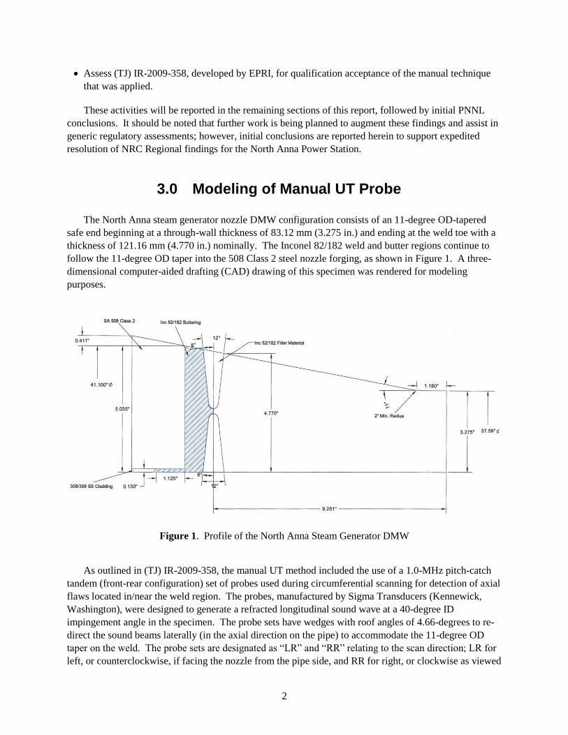
The North Anna steam generator nozzle DMW configuration consists of an 11-degree OD-tapered
safe end beginning at a through-wall thickness of 83.12 mm (3.275 in.) and ending at the weld toe with a
thickness of 121.16 mm (4.770 in.) nominally. The Inconel 82/182 weld and butter regions continue to
follow the 11-degree OD taper into the 508 Class 2 steel nozzle forging, as shown in Figure 1. A three-
dimensional computer-aided drafting (CAD) drawing of this specimen was rendered for modeling
purposes.
Figure 1. Profile of the North Anna Steam Generator DMW
As outlined in (TJ) IR-2009-358, the manual UT method included the use of a 1.0-MHz pitch-catch
tandem (front-rear configuration) set of probes used during circumferential scanning for detection of axial
flaws located in/near the weld region. The probes, manufactured by Sigma Transducers (Kennewick,
Washington), were designed to generate a refracted longitudinal sound wave at a 40-degree ID
impingement angle in the specimen. The probe sets have wedges with roof angles of 4.66-degrees to re-
direct the sound beams laterally (in the axial direction on the pipe) to accommodate the 11-degree OD
taper on the weld. The probe sets are designated as ―LR‖ and ―RR‖ relating to the scan direction; LR for
left, or counterclockwise, if facing the nozzle from the pipe side, and RR for right, or clockwise as viewed
3
from the pipe side. Sigma Transducers was contacted and provided the details of the integral
probe/wedge configurations; these can be found in Table 1. The information in Table 1 is for the LR
probe set, and only this direction has been modeled; the RR probe set would produce a mirror image if
modeled.
Table 1. Tandem Probe Description
Design 2007 Integral Probe/Wedge
Manufacturer Sigma Transducers
Frequency 1.0 MHz
Bandwidth 52% at -6dB
Damping material Backed, not inductively tuned
Angle/mode 40-degree L
Examination type Circumferential scan
Element size 2 (25 25) mm [2 (1.0 1.0) in.]
Pulser-receiver Front-transmit; rear-receive
Wedge material Low 10
Wedge velocity 2449 m/s (0.964 in/µs)
Separation 0.76-mm (30-mil) cork material
Contour 533.4-mm (21-in.) radius
Front Wedge Length 25.65 mm (1.01 in.)
Width 25.4 mm (1.0 in.)
Height 4.72-mm (0.186-in.) low point
Incident angle 9.0 degrees
Roof angle 4.66 degrees
Back Wedge Length 27.84 mm (1.096 in.)
Width 25.4 mm (1.0 in.)
Height 4.55-mm (0.179-in.) low point
Incident angle 13.707 degrees
Roof angle 4.66 degrees
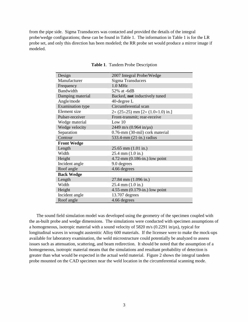
The sound field simulation model was developed using the geometry of the specimen coupled with
the as-built probe and wedge dimensions. The simulations were conducted with specimen assumptions of
a homogeneous, isotropic material with a sound velocity of 5820 m/s (0.2291 in/µs), typical for
longitudinal waves in wrought austenitic Alloy 600 materials. If the licensee were to make the mock-ups
available for laboratory examination, the weld microstructure could potentially be analyzed to assess
issues such as attenuation, scattering, and beam redirection. It should be noted that the assumption of a
homogeneous, isotropic material means that the simulations and resultant probability of detection is
greater than what would be expected in the actual weld material. Figure 2 shows the integral tandem
probe mounted on the CAD specimen near the weld location in the circumferential scanning mode.
4
Figure 2. Tandem Probe Setup on DMW Specimen
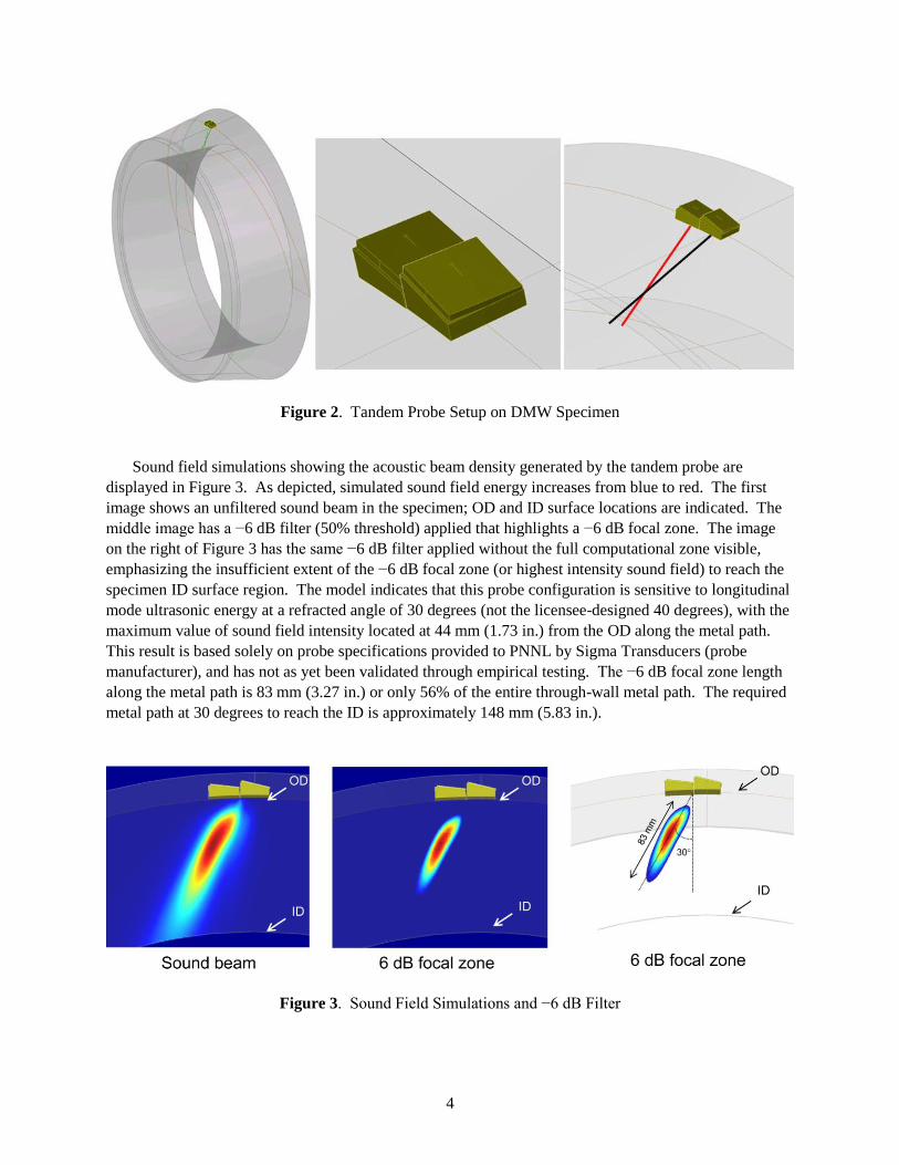
Sound field simulations showing the acoustic beam density generated by the tandem probe are
displayed in Figure 3. As depicted, simulated sound field energy increases from blue to red. The first
image shows an unfiltered sound beam in the specimen; OD and ID surface locations are indicated. The
middle image has a −6 dB filter (50% threshold) applied that highlights a −6 dB focal zone. The image
on the right of Figure 3 has the same −6 dB filter applied without the full computational zone visible,
emphasizing the insufficient extent of the −6 dB focal zone (or highest intensity sound field) to reach the
specimen ID surface region. The model indicates that this probe configuration is sensitive to longitudinal
mode ultrasonic energy at a refracted angle of 30 degrees (not the licensee-designed 40 degrees), with the
maximum value of sound field intensity located at 44 mm (1.73 in.) from the OD along the metal path.
This result is based solely on probe specifications provided to PNNL by Sigma Transducers (probe
manufacturer), and has not as yet been validated through empirical testing. The −6 dB focal zone length
along the metal path is 83 mm (3.27 in.) or only 56% of the entire through-wall metal path. The required
metal path at 30 degrees to reach the ID is approximately 148 mm (5.83 in.).
Figure 3. Sound Field Simulations and −6 dB Filter
5
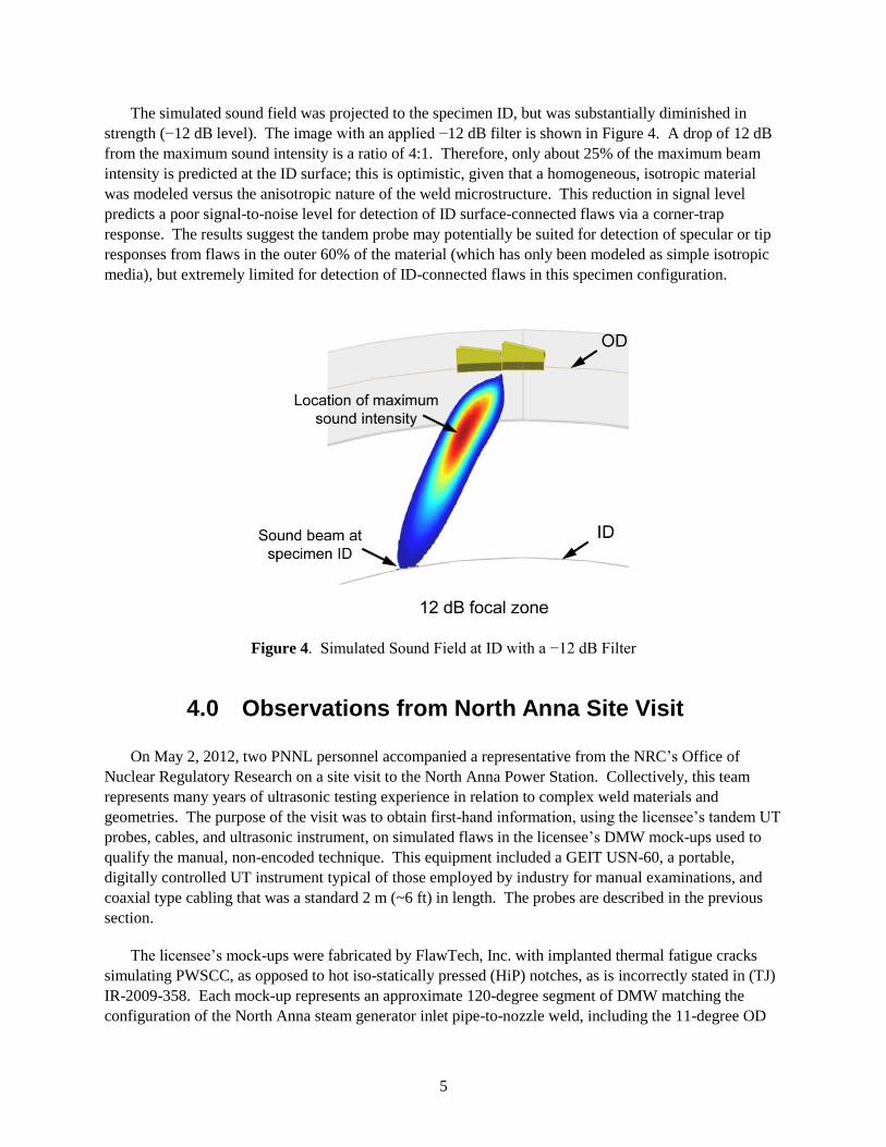
The simulated sound field was projected to the specimen ID, but was substantially diminished in
strength (−12 dB level). The image with an applied −12 dB filter is shown in Figure 4. A drop of 12 dB
from the maximum sound intensity is a ratio of 4:1. Therefore, only about 25% of the maximum beam
intensity is predicted at the ID surface; this is optimistic, given that a homogeneous, isotropic material
was modeled versus the anisotropic nature of the weld microstructure. This reduction in signal level
predicts a poor signal-to-noise level for detection of ID surface-connected flaws via a corner-trap
response. The results suggest the tandem probe may potentially be suited for detection of specular or tip
responses from flaws in the outer 60% of the material (which has only been modeled as simple isotropic
media), but extremely limited for detection of ID-connected flaws in this specimen configuration.
Figure 4. Simulated Sound Field at ID with a −12 dB Filter
4.0 Observations from North Anna Site Visit
On May 2, 2012, two PNNL personnel accompanied a representative from the NRC’s Office of
Nuclear Regulatory Research on a site visit to the North Anna Power Station. Collectively, this team
represents many years of ultrasonic testing experience in relation to complex weld materials and
geometries. The purpose of the visit was to obtain first-hand information, using the licensee’s tandem UT
probes, cables, and ultrasonic instrument, on simulated flaws in the licensee’s DMW mock-ups used to
qualify the manual, non-encoded technique. This equipment included a GEIT USN-60, a portable,
digitally controlled UT instrument typical of those employed by industry for manual examinations, and
coaxial type cabling that was a standard 2 m (~6 ft) in length. The probes are described in the previous
section.
The licensee’s mock-ups were fabricated by FlawTech, Inc. with implanted thermal fatigue cracks
simulating PWSCC, as opposed to hot iso-statically pressed (HiP) notches, as is incorrectly stated in (TJ)
IR-2009-358. Each mock-up represents an approximate 120-degree segment of DMW matching the
configuration of the North Anna steam generator inlet pipe-to-nozzle weld, including the 11-degree OD
6
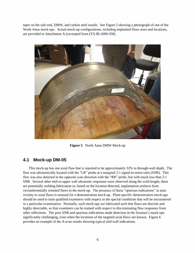
taper on the safe end, DMW, and carbon steel nozzle. See Figure 5 showing a photograph of one of the
North Anna mock-ups. Actual mock-up configurations, including implanted flaws sizes and locations,
are provided in Attachment A [excerpted from (TJ) IR-2009-358].
Figure 5. North Anna DMW Mock-up
4.1 Mock-up DM-05
This mock-up has one axial flaw that is reported to be approximately 32% in through-wall depth. The
flaw was ultrasonically located with the ―LR‖ probe at a marginal 2:1 signal-to-noise ratio (SNR). This
flaw was also detected in the opposite scan direction with the ―RR‖ probe, but with much less than 2:1
SNR. Several other mid-to-upper wall ultrasonic responses were observed along the weld length; these
are potentially welding fabrication or, based on the location detected, implantation artifacts from
circumferentially oriented flaws in the mock-up. The presence of these ―spurious indications‖ in near
vicinity to axial flaws is unusual for a demonstration mock-up. Plant-specific demonstration mock-ups
should be used to train qualified examiners with respect to the special conditions that will be encountered
in a particular examination. Normally, such mock-ups are fabricated such that flaws are discrete and
highly detectable, so that examiners can be trained with respect to discriminating flaw responses from
other reflections. The poor SNR and spurious indications made detection in the licensee’s mock-ups
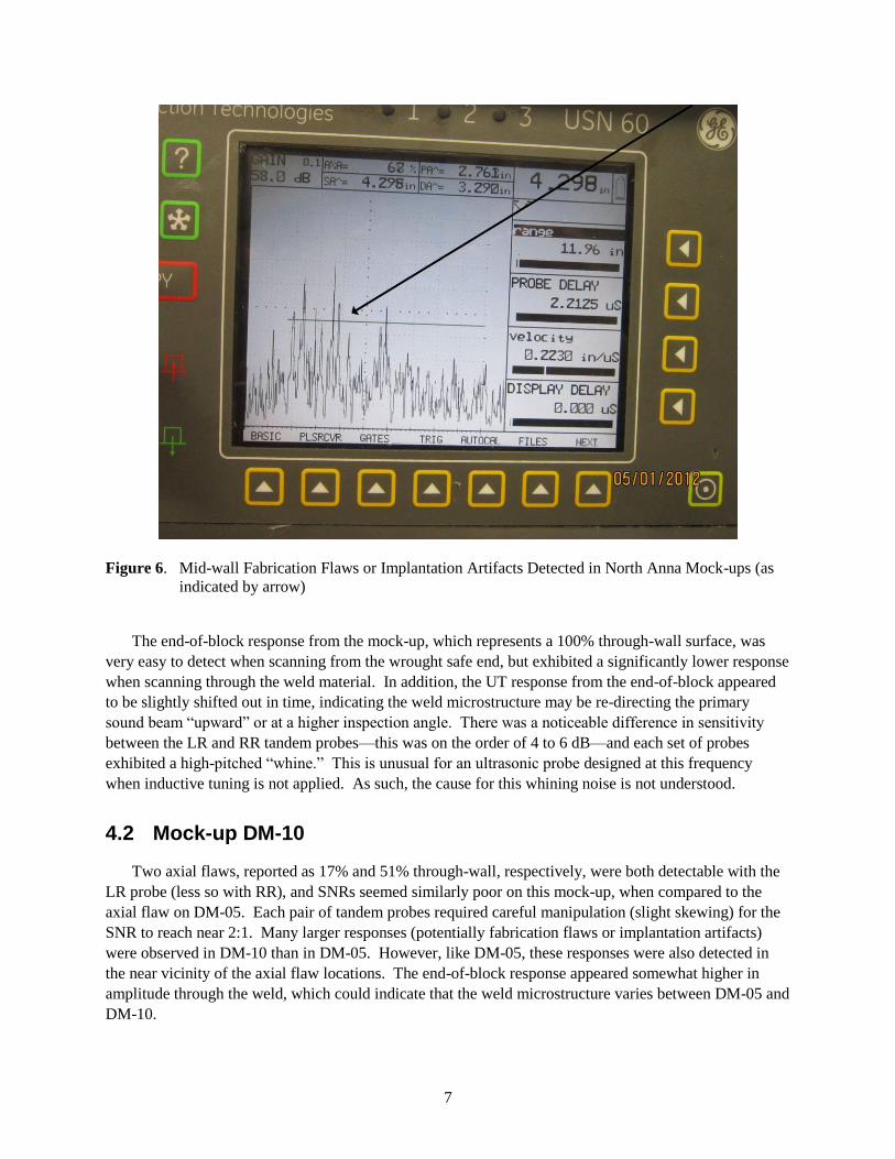
significantly challenging, even when the locations of the targeted axial flaws are known. Figure 6
provides an example of the A-scan results showing typical mid-wall indications.
7
Figure 6. Mid-wall Fabrication Flaws or Implantation Artifacts Detected in North Anna Mock-ups (as
indicated by arrow)
The end-of-block response from the mock-up, which represents a 100% through-wall surface, was
very easy to detect when scanning from the wrought safe end, but exhibited a significantly lower response
when scanning through the weld material. In addition, the UT response from the end-of-block appeared
to be slightly shifted out in time, indicating the weld microstructure may be re-directing the primary
sound beam ―upward‖ or at a higher inspection angle. There was a noticeable difference in sensitivity
between the LR and RR tandem probes—this was on the order of 4 to 6 dB—and each set of probes
exhibited a high-pitched ―whine.‖ This is unusual for an ultrasonic probe designed at this frequency
when inductive tuning is not applied. As such, the cause for this whining noise is not understood.
4.2 Mock-up DM-10
Two axial flaws, reported as 17% and 51% through-wall, respectively, were both detectable with the
LR probe (less so with RR), and SNRs seemed similarly poor on this mock-up, when compared to the
axial flaw on DM-05. Each pair of tandem probes required careful manipulation (slight skewing) for the
SNR to reach near 2:1. Many larger responses (potentially fabrication flaws or implantation artifacts)
were observed in DM-10 than in DM-05. However, like DM-05, these responses were also detected in
the near vicinity of the axial flaw locations. The end-of-block response appeared somewhat higher in
amplitude through the weld, which could indicate that the weld microstructure varies between DM-05 and
DM-10.
8
General observation—Given these mock-ups are claimed to be designed/fabricated to be consistent
with ASME, Appendix VIII (ASME 2007), one would expect less inadvertent fabrication flaw, or
implantation artifact, responses to be present. The UT responses from these artifacts, or weld fabrication
flaws (this remains unclear), significantly impede detection and characterization of the axial flaws. Based
on the site observations, there are too many transient indications detected on the North Anna mock-ups
that interfere with targeted flaws for one to clearly assess the effectiveness of this non-encoded, manual
system to detect the implanted cracks. Typical A-scan images for the flaws and other pertinent reflections
on DM-05 and DM-10 are included as Attachment B.
5.0 Assessment of EPRI Technical Justification
A review was performed on several documents that are related to the inspection of the North Anna
steam generator nozzle dissimilar metal weld configuration. The documents reviewed included Technical
Justification for the Acceptance of Ultrasonic Examination Demonstration Results on North Anna Steam
Generator Nozzle Dissimilar Metal Weld Configurations with PDI-UT-10, Rev. C (IR-2009-358) (EPRI
2009); Generic Procedure for the Ultrasonic Examination of Dissimilar Metal Welds, Rev. C (EPRI
2006); and Performance Demonstration Initiative (PDI) - Dissimilar Metal Weld Mock-Up Criteria
Rev. A (EPRI 2004).
The PDI mock-ups were developed on the basis that certain weld geometries were plant-specific, and
individual plants should be responsible for these types of mock-ups. As such, the DMW configurations
that are represented in the blind test sets used at PDI to meet ASME Code, Appendix VIII, Supplement 10
requirements, are only those that are generic, or would typically be found in many plants. As a result, a
guidance document was developed containing the criteria that site-specific mock-ups must meet. It is
further stated in the abstract and introduction of (TJ) IR-2009-358 that site-specific mock-ups are used to
optimize essential inspection variables and to demonstrate the effectiveness of the examination for the
site-specific geometry. In the Abstract and Introduction Sections of the technical justification, essential
variables that are allowed revision, or optimization, include:
Alternative search unit angles
Element size, focal depths, and contours of the search units
Selection of compound angles to accommodate unique configurations (tapered inspection surfaces)
Adjustment to scan patterns to compensate for limited access
Other essential inspection variables as required.
As can be seen, this is a very broad statement that goes well beyond only ―optimizing‖ essential
inspection variables. In fact, this wording would appear to allow extension of, or deviation from,
essential variables without the need to re-qualify a procedure, as is required by ASME Code, Section XI,
Appendix VIII-3400. This approach undermines the intent of Appendix VIII to ensure that all inspections
go through blind performance demonstrations to prove they are effective and robust. Furthermore,
Appendix VIII, Supplement 10, Paragraph 4.0(d) requires that to qualify new essential variables, at least
one personnel performance demonstration set is needed. Clearly, this requirement is not being met by
what is allowed in (TJ) IR-2009-358, as applied at North Anna. Further, though Section 3 of (TJ) IR-
2009-358 assumes that the mock-up conditions are representative of actual in-service components, it is
9
unclear whether the North Anna mock-ups adequately represent in-situ weld conditions, and the
corresponding UT responses that would be expected for geometrical and metallurgical features in field
welds. A review of the phased array UT data recently acquired on the North Anna DMWs could be
compared to similar data on the licensee mock-ups to further assess this issue.
In Sections 4, 5, and 6 of (TJ) IR-2009-358, it is stated several times that changes in refracted angles
were used to compensate for the North Anna 11-degree OD taper, but no modeling results or other
calculations are included to support the position that impingement angles remain the same as those
demonstrated during the original PDI qualification process. In addition, it would seem prudent to address
the transducer aperture (overall size) at the frequency used so that one could confidently state that
sufficient sound field energies would be present in the component to adequately insonify and detect flaws.
This is a critical point and modeling results for the sound fields that were originally demonstrated along
with those for the substituted transducers need to be presented in order to begin to build a case that
ensures inspection performance has not been reduced or compromised. Yet, this basic acoustic
information is not described in (TJ) IR-2009-358.
In Section 7 of (TJ) IR-2009-358, Table 7-1 and criteria paragraph 4.7.7, it is stated, ―This mock-up
was not commercially dedicated.‖ The meaning of this statement is unclear. Further, under item 4.3 the
document states, ―An adequate number of flaws were strategically placed ---.‖ However, at a minimum,
the number of flaws should be representative of a single, full personnel performance demonstration set of
flaws, according to Appendix VIII, Supplement 10, Paragraph 4.0(d). The mock-ups used by the licensee
do not meet this criterion.
In the (TJ) IR-2009-358 (Section 8), it is stated, ―For circumferential scans, the examinations can be
performed from both nozzle and safe-end sides including the attachment weld area.‖ When using
conventional probes on DMWs having no, or minimal, OD taper, this is possible because the sound beam
can be directed, or skewed, into the weld ID-area from the safe end and/or occasionally from the nozzle
side. However, the tandem probe configuration at North Anna, which uses OD surface-conforming
integral wedges to account for the diameter of the piping, may have effectively eliminated this option
because of the lateral skew designed into the integral wedges to account for the 11-degree OD taper. In
theory, this re-direction of the sound beam, via wedge roof angles, is necessary to produce a sound field at
the correct orientation (relative to the axial direction of the pipe) at the ID surface in this narrow weld
region. Therefore, the only transducer placement area for which the sound would be skewed properly is
directly over the weld OD surface, and an attempt to use this tandem configuration from either the safe
end or nozzle side would not re-direct the sound beam into the correct weld area to detect PWSCC, if it
occurs.
With respect to the number of relevant axial flaws in the mock-ups for conducting the non-blind
demonstration, (TJ) IR-2009-358 states that two of the three axial flaws that exist in the North Anna
mock-ups are ―out of range‖ as specified in PDI Dissimilar Metal Weld Mockup Criteria, Rev. A and are
for ―information only.‖ This implies that only one axial mock-up flaw could be used to assess inspection
technique validity, since two of the three axial flaws are essentially ―out-of-compliance‖ with the mock-
up criteria; this could significantly impact the rigor of the demonstration for axial flaw detection.
In Section 9 of (TJ) IR-2009-358, it is stated under the headings of Ultrasonic Hardware, Cabling and
Transducers, that ―No previous transducer and ultrasonic equipment combinations exist.‖ However, it is
assumed that some combination of these items had been demonstrated at PDI for initially meeting
10
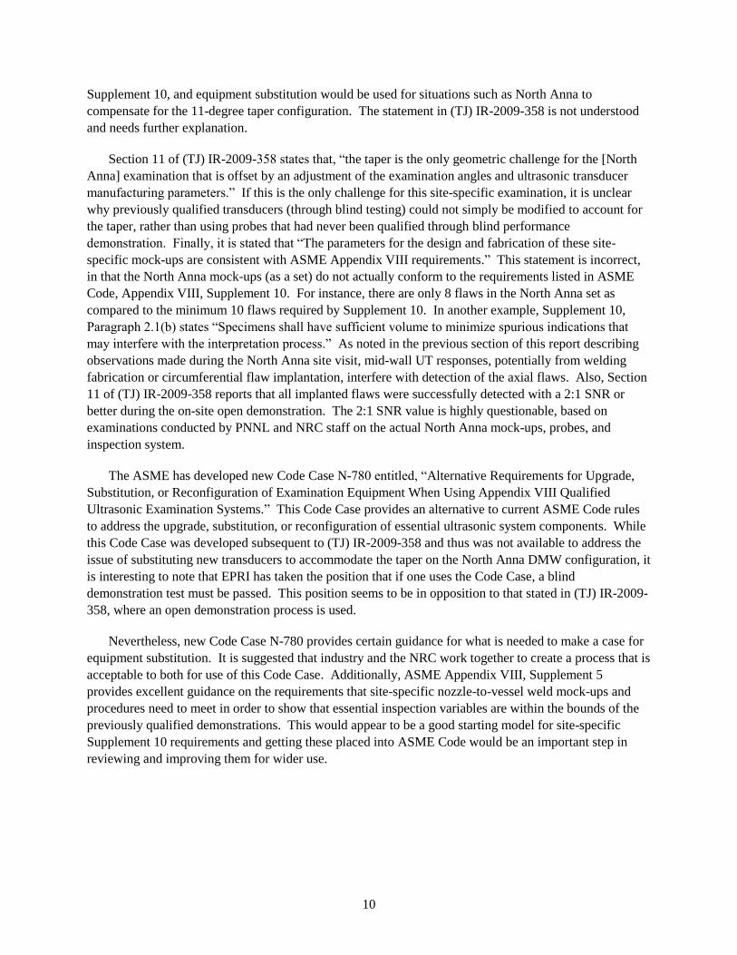
Supplement 10, and equipment substitution would be used for situations such as North Anna to
compensate for the 11-degree taper configuration. The statement in (TJ) IR-2009-358 is not understood
and needs further explanation.
Section 11 of (TJ) IR-2009-358 states that, ―the taper is the only geometric challenge for the [North
Anna] examination that is offset by an adjustment of the examination angles and ultrasonic transducer
manufacturing parameters.‖ If this is the only challenge for this site-specific examination, it is unclear
why previously qualified transducers (through blind testing) could not simply be modified to account for
the taper, rather than using probes that had never been qualified through blind performance
demonstration. Finally, it is stated that ―The parameters for the design and fabrication of these site-
specific mock-ups are consistent with ASME Appendix VIII requirements.‖ This statement is incorrect,
in that the North Anna mock-ups (as a set) do not actually conform to the requirements listed in ASME
Code, Appendix VIII, Supplement 10. For instance, there are only 8 flaws in the North Anna set as
compared to the minimum 10 flaws required by Supplement 10. In another example, Supplement 10,
Paragraph 2.1(b) states ―Specimens shall have sufficient volume to minimize spurious indications that
may interfere with the interpretation process.‖ As noted in the previous section of this report describing
observations made during the North Anna site visit, mid-wall UT responses, potentially from welding
fabrication or circumferential flaw implantation, interfere with detection of the axial flaws. Also, Section
11 of (TJ) IR-2009-358 reports that all implanted flaws were successfully detected with a 2:1 SNR or
better during the on-site open demonstration. The 2:1 SNR value is highly questionable, based on
examinations conducted by PNNL and NRC staff on the actual North Anna mock-ups, probes, and
inspection system.
The ASME has developed new Code Case N-780 entitled, ―Alternative Requirements for Upgrade,
Substitution, or Reconfiguration of Examination Equipment When Using Appendix VIII Qualified
Ultrasonic Examination Systems.‖ This Code Case provides an alternative to current ASME Code rules
to address the upgrade, substitution, or reconfiguration of essential ultrasonic system components. While
this Code Case was developed subsequent to (TJ) IR-2009-358 and thus was not available to address the
issue of substituting new transducers to accommodate the taper on the North Anna DMW configuration, it
is interesting to note that EPRI has taken the position that if one uses the Code Case, a blind
demonstration test must be passed. This position seems to be in opposition to that stated in (TJ) IR-2009-
358, where an open demonstration process is used.
Nevertheless, new Code Case N-780 provides certain guidance for what is needed to make a case for
equipment substitution. It is suggested that industry and the NRC work together to create a process that is
acceptable to both for use of this Code Case. Additionally, ASME Appendix VIII, Supplement 5
provides excellent guidance on the requirements that site-specific nozzle-to-vessel weld mock-ups and
procedures need to meet in order to show that essential inspection variables are within the bounds of the
previously qualified demonstrations. This would appear to be a good starting model for site-specific
Supplement 10 requirements and getting these placed into ASME Code would be an important step in
reviewing and improving them for wider use.
11
6.0 Conclusions
The failure of the licensee’s UT technique to detect multiple, deep through-wall cracks on the subject
DMW erodes confidence in nondestructive examination techniques that are being applied for site-specific
PWSCC inspections, and further, casts doubt on certain protocols being used under the auspices of PDI
for qualification of procedures, personnel, and equipment.
Ultrasonic modeling of specific probe parameters for the manual examinations employed on the
subject DMW configuration at North Anna indicates that insufficient acoustic energy would be available
near the inner surface of the weld to assure detection of ID surface-connected axially oriented flaws.
These results further suggest inadequate performance for manual, real-time examinations to properly
discriminate and characterize surface-connected flaws from other welding or metallurgical features in the
inner one-third of the weld volume on these DMWs. This finding is corroborated by site observations
that show low SNR for the targeted mock-up flaws in the presence of spurious indications that interfere
with detection and classification of simulated ID-connected cracks.
The technical justification lists the probe’s angle as being 40 degrees as impinged on the ID surface.
Modeling shows that the effective angle for the subject probe configuration is, in actuality, approximately
30 degrees. The apparent discrepancy places the licensee’s use of this probe out of compliance with their
own procedure and (TJ) IR-2009-358. It should be noted that this angle discrepancy is based solely on
modeling, given the probe parameters provided by the manufacturer, as no empirical tests have been
performed to validate these results. Based on site observations of all UT responses in the North Anna
mock-ups, one would not expect the applied manual, non-encoded technique to consistently detect axial
flaws (with low numbers of false calls) without examiners having prior knowledge of where these flaws
are located. Thus, if the mock-ups, tandem probes, and scanning techniques used at North Anna were
subjected to blind performance demonstrations using realistic implanted flaws, the procedure would, in
our estimation, have significantly poor qualification pass rates.
As noted in Section 4.0, site observations revealed too many transient indications in the North Anna
mock-ups that interfere with targeted flaws for one to clearly assess the effectiveness of this non-encoded,
manual system to detect cracks. In addition, site observations of the UT responses for the simulated flaws
implanted in the mock-ups and other fabrication features raised questions with respect to whether the
mock-ups represent typical metallurgical and other fabrication features of DMWs in-situ. In order to
sufficiently judge the adequacy of protocols being used under the auspices of PDI for qualification of
procedures, personnel, and equipment, it would be necessary to acquire comparable data on both the field
welds and mock-ups.
The technical justification developed to extend PDI qualifications to North Anna DMWs has been
found inadequate to make a reasonable case for using the manual, non-encoded procedure that was
employed. The primary issue associated with (TJ) IR-2009-358 is one of allowing essential variables to
be changed without providing sufficient technical bases for these changes. For instance, a physics-based
technical assessment, either through calculations or modeling, has not been included to support the
manual tandem probe design. The condition of the mock-ups, as fabricated, and the ―open‖ nature of the
site qualifications, raise further concerns relative to the validity of (TJ) IR-2009-358 to justify changes in
demonstrated variables (essential or non-essential) necessary to accommodate the 11-degree taper on the
subject DMW configuration at North Anna. Therefore, the effectiveness of these changes is questionable.
12
Considering these issues, it has been determined that the site-specific approach implemented at North
Anna does not meet the intent or stated requirements of Appendix VIII.
ASME Appendix VIII is a framework that has been developed to support procedure, personnel, and
equipment (UT system) qualifications through rigorous and statistically based testing protocols.
Technical justifications such as (TJ) IR-2009-358, as written, enable licensees to implement changes to
any essential variable in a qualified procedure simply by stating that this change is necessary for
implementation at their site. This approach enables licensees to bypass Appendix VIII requirements and,
therefore, potentially erode the expected performance of qualified UT systems. Code Case N-780
provides a much more robust methodology for implementing such changes in essential variables.
Finally, there appears to be an inconsistency with respect to the application of robust, blind
demonstration approaches versus less rigorous, open qualifications. This issue has been highlighted as a
result of the North Anna incident, where the licensee requested that EPRI review (TJ) IR-2009-358 to re-
assess the current validity of the information provided within this document. With respect to the open
demonstration process, EPRI has determined the stated position (of using an open demonstration process)
in (TJ) IR-2009-358 to continue to be acceptable, which is inconsistent with their approach to the use of
Code Case N-780, where EPRI requires that a blind demonstration test be passed. This inconsistency
needs to be further discussed and a path forward defined in order to develop guidance for application
during either type of performance demonstration.
7.0 References
ASME. 2007. "Section XI, Rules for Inservice Inspection of Nuclear Power Plant Components;
Appendix VIII, Performance Demonstration Requirements for Ultrasonic Examination Systems." In 2007
ASME Boiler and Pressure Vessel Code – An International Code. American Society of Mechanical
Engineers, New York.
EPRI. 2004. Performance Demonstration Initiative (PDI) - Dissimilar Metal Weld Mock-Up Criteria
REV A. Electric Power Research Institute, Palo Alto, California.
EPRI. 2006. Generic Procedure for the Ultrasonic Examination of Dissimilar Metal Welds. PDI UT-
10, Revision C, Electric Power Research Institute, Palo Alto, California.
EPRI. 2009. Technical Justification for the Acceptance of Ultrasonic Examination Demonstration
Results on North Anna Steam Generator Nozzle Dissimilar Metal Weld Configurations with PDI-UT-10,
Rev. C. IR-2009-358, Electric Power Research Institute, Palo Alto, California.

Appendix A
Description of North Anna Mock-ups

A.1
Appendix A
Description of North Anna Mock-ups
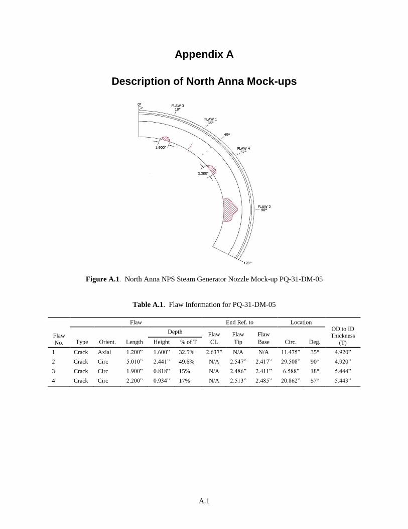
Figure A.1. North Anna NPS Steam Generator Nozzle Mock-up PQ-31-DM-05
Table A.1. Flaw Information for PQ-31-DM-05
Flaw
No.
Flaw End Ref. to Location OD to ID
Thickness
(T) Type Orient. Length
Depth Flaw
CL
Flaw
Tip
Flaw
Base Circ. Deg. Height % of T
1 Crack Axial 1.200‖ 1.600‖ 32.5% 2.637‖ N/A N/A 11.475‖ 35° 4.920‖
2 Crack Circ 5.010‖ 2.441‖ 49.6% N/A 2.547‖ 2.417‖ 29.508‖ 90° 4.920‖
3 Crack Circ 1.900‖ 0.818‖ 15% N/A 2.486‖ 2.411‖ 6.588‖ 18° 5.444‖
4 Crack Circ 2.200‖ 0.934‖ 17% N/A 2.513‖ 2.485‖ 20.862‖ 57° 5.443‖
A.2
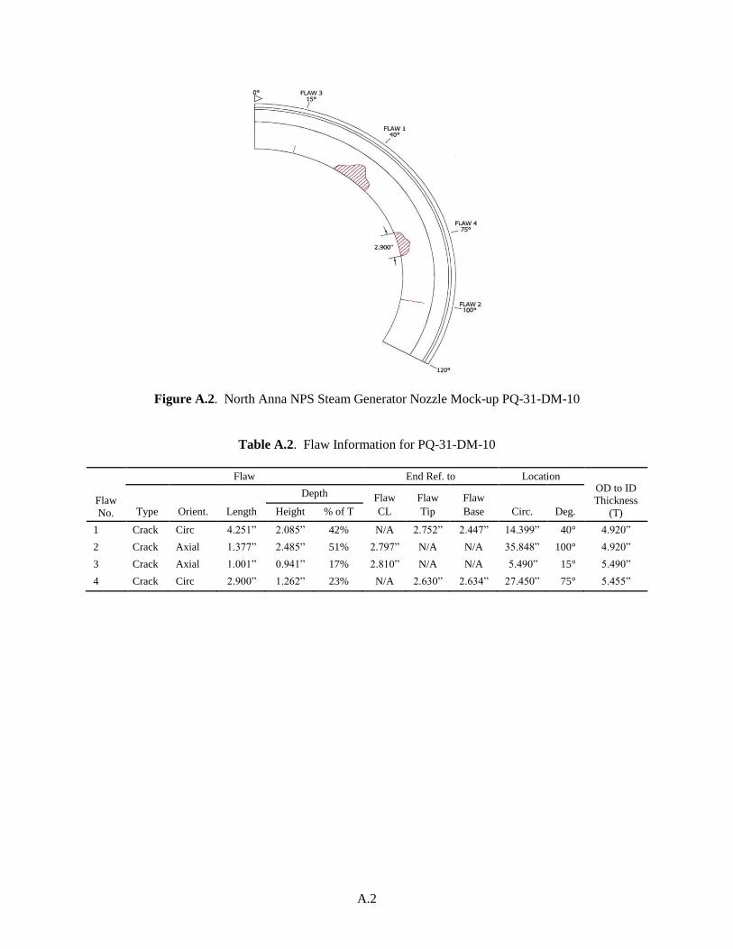
Figure A.2. North Anna NPS Steam Generator Nozzle Mock-up PQ-31-DM-10
Table A.2. Flaw Information for PQ-31-DM-10
Flaw
No.
Flaw End Ref. to Location OD to ID
Thickness
(T) Type Orient. Length
Depth Flaw
CL
Flaw
Tip
Flaw
Base Circ. Deg. Height % of T
1 Crack Circ 4.251‖ 2.085‖ 42% N/A 2.752‖ 2.447‖ 14.399‖ 40° 4.920‖
2 Crack Axial 1.377‖ 2.485‖ 51% 2.797‖ N/A N/A 35.848‖ 100° 4.920‖
3 Crack Axial 1.001‖ 0.941‖ 17% 2.810‖ N/A N/A 5.490‖ 15° 5.490‖
4 Crack Circ 2.900‖ 1.262‖ 23% N/A 2.630‖ 2.634‖ 27.450‖ 75° 5.455‖
Appendix B
A-scans on North Anna Mock-ups

DRAFT
B.1
Appendix B
A-scans on North Anna Mock-ups
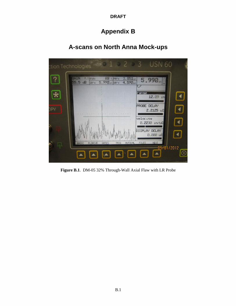
Figure B.1. DM-05 32% Through-Wall Axial Flaw with LR Probe
DRAFT
B.2
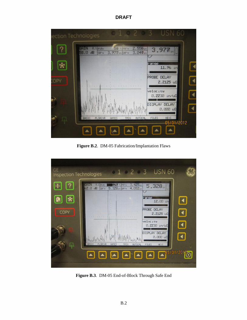
Figure B.2. DM-05 Fabrication/Implantation Flaws
Figure B.3. DM-05 End-of-Block Through Safe End
DRAFT
B.3
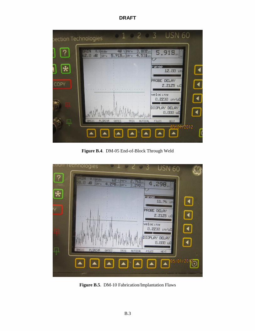
Figure B.4. DM-05 End-of-Block Through Weld
Figure B.5. DM-10 Fabrication/Implantation Flaws
DRAFT
B.4
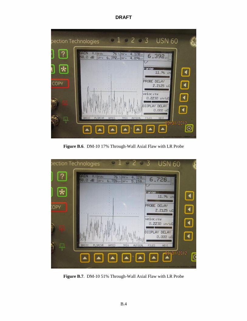
Figure B.6. DM-10 17% Through-Wall Axial Flaw with LR Probe
Figure B.7. DM-10 51% Through-Wall Axial Flaw with LR Probe


DRAFT


![AN4841, S12ZVL LIN Enabled Ultrasonic Distance … cotton and wool absorb the majority of ultrasonic waves, so it may be difficult to detect these objects [2]. 2.2 Required compensation](https://img.pdfslide.net/doc/110x75/5abd8d7d7f8b9a7e418bc38e/an4841-s12zvl-lin-enabled-ultrasonic-distance-cotton-and-wool-absorb-the-majority.jpg)


![Ultrasonic Testing of Rails Using Phased Array - ndt.net · Ultrasonic testing is widely employed for Non-destructive Testing (NDT) [1] of test objects to detect and analyse anomalies](https://img.pdfslide.net/doc/110x75/5b4f2ad37f8b9a3e6e8bc326/ultrasonic-testing-of-rails-using-phased-array-ndtnet-ultrasonic-testing.jpg)