Embed Size (px)
Citation preview
636 © 2016 Nigerian Journal of Clinical Practice | Published by Wolters Kluwer - Medknow
AbstractBackground and Purpose: The purpose of this study was to evaluate the internal and marginal fit of chrome cobalt (Co‑Cr) crowns were fabricated with laser sintering, computer‑aided design (CAD) and computer‑aided manufacturing, and conventional methods.Materials and Methods: Polyamide master and working models were designed and fabricated. The models were initially designed with a software application for three‑dimensional (3D) CAD (Maya, Autodesk Inc.). All models were fabricated models were produced by a 3D printer (EOSINT P380 SLS, EOS). 128 1‑unit Co‑Cr fixed dental prostheses were fabricated with four different techniques: Conventional lost wax method, milled wax with lost‑wax method (MWLW), direct laser metal sintering (DLMS), and milled Co‑Cr (MCo‑Cr). The cement film thickness of the marginal and internal gaps was measured by an observer using a stereomicroscope after taking digital photos in ×24.Results: Best fit rates according to mean and standard deviations of all measurements was in DLMS both in premolar (65.84) and molar (58.38) models in µm. A significant difference was found DLMS and the rest of fabrication techniques (P < 0.05). No significant difference was found between MCo‑CR and MWLW in all fabrication techniques both in premolar and molar models (P > 0.05).Conclusion: DMLS was best fitting fabrication techniques for single crown based on the results.The best fit was found in marginal; the larger gap was found in occlusal.All groups were within the clinically acceptable misfit range.
Key words: Chrome‑cobalt, computer‑aided design and computer‑aided manufacturing, internal fit, laser sintering, marginal fit, single crown
Date of Acceptance: 03‑Nov‑2014
Address for correspondence: Dr. S Gunsoy, Department of Prosthodontics, Faculty of Dentistry, Near East University, Nicosia, Northern Cyprus, Mersin 10, Turkey. E‑mail: [email protected]
Introduction
Metal based ceramic restoration are still the most common used for fixed partial dentures such as crowns and bridges.[1] In order
to have a suitable and successful restorations, the clinicians should be focused on both qualitative and quantitative assessments. One of aspect of this assessment to evaluate the marginal adaptation of crown and bridge restorations.[2] The ideal internal or marginal adaptation will result in minimal
Evaluation of marginal/internal fit of chrome‑cobalt crowns: Direct laser metal sintering versus computer‑aided design and computer‑aided
manufacturing
S Gunsoy, M Ulusoy
Department of Prosthodontics, Faculty of Dentistry, Near East University, Nicosia, Northern Cyprus, Mersin 10, Turkey
Access this article online
Quick Response Code:Website: www.njcponline.com
DOI: 10.4103/1119-3077.188699
PMID: *******
How to cite this article: Gunsoy S, Ulusoy M. Evaluation of marginal/internal fit of chrome‑cobalt crowns: Direct laser metal sintering versus computer‑aided design and computer‑aided manufacturing. Niger J Clin Pract 2016;19:636‑44.
This is an open access article distributed under the terms of the Creative Commons Attribution‑NonCommercial‑ShareAlike 3.0 License, which allows others to remix, tweak, and build upon the work non‑commercially, as long as the author is credited and the new creations are licensed under the identical terms.
For reprints contact: [email protected]
Original Article
[Downloaded free from http://www.njcponline.com on Tuesday, August 23, 2016, IP: 165.255.151.187]
Gunsoy and Ulusoy: DMLS vs CAD/CAM
637Nigerian Journal of Clinical Practice • Sep-Oct 2016 • Vol 19 • Issue 5
plaque accumulation and also diminish the carious lesion, bone loss, and periodontal diseases under the restorations.[3]
There have been numerous studies on marginal adaptation for fixed partial dentures. Previous studies using different materials and techniques showed a wide range of reported values of marginal and internal fit.[3‑8] In the fabrication of cast metal restorations, the lost‑wax casting technique is one of the most widely used methods.[9,10] However, in recent years, technological methods, which are more efficient, began to be used instead of conventional methods. Technology and equipment from other industries have regularly been adapted for use in the dental industry. Scanners, both model and intraoral, have their roots in other markets. Most of the computer‑aided manufacturing (CAM) milling systems in use today in dental laboratory production processes came from other industries. Thus, three‑dimensional (3D) printing and rapid prototyping technologies used in general manufacturing have joined computer‑aided design (CAD) and CAM milling and scanning as an emerging and new technology in dentistry.[6,8,9]
The use of this new technology machinery, as well as speed up production, allows significant savings in the production costs. All of these reasons, manufacturers increasingly are choosing these production methods. Another important point in addition to these advantages is the adaptation of restorations. Most of the prosthetic treatments are fixed dentures which their aims restore function, esthetics, and phonation.[5] The durability of these restorations depends on their compatibilities with tooth and periodontal tissues. Underfitting of restoration causes some problems such as bacterial plaque retention areas, secondary caries, periodontal inflammation, and increased microleakage.[3] Because of these factors, treatment success depends on the perfect fit between the tooth and the restoration.
The aim of this study was to evaluate and compare the internal and marginal fit in vitro of single crowns using four different fabrication techniques using laser sintering, CAD/CAM, and conventional methods. The null hypothesis was that significant difference would be found with laser sintering with other techniques.
Materials and Methods
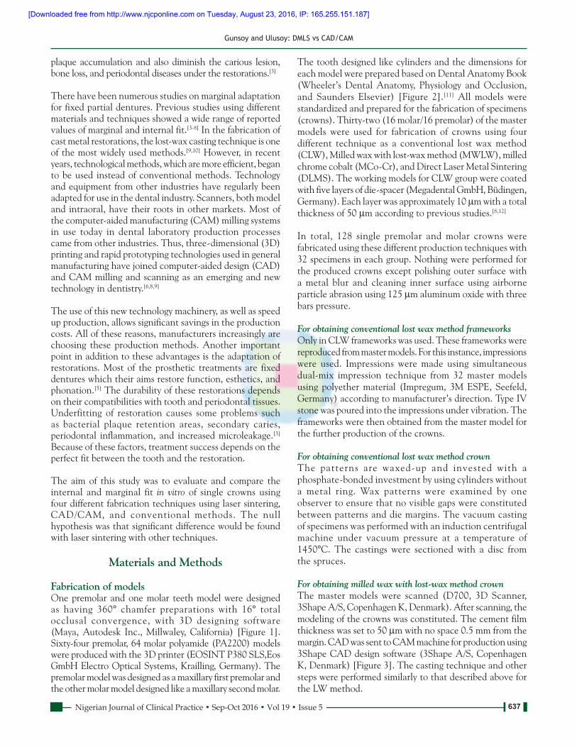
Fabrication of modelsOne premolar and one molar teeth model were designed as having 360° chamfer preparations with 16° total occlusal convergence, with 3D designing software (Maya, Autodesk Inc., Millwaley, California) [Figure 1]. Sixty‑four premolar, 64 molar polyamide (PA2200) models were produced with the 3D printer (EOSINT P380 SLS,Eos GmbH Electro Optical Systems, Krailling, Germany). The premolar model was designed as a maxillary first premolar and the other molar model designed like a maxillary second molar.
The tooth designed like cylinders and the dimensions for each model were prepared based on Dental Anatomy Book (Wheeler’s Dental Anatomy, Physiology and Occlusion, and Saunders Elsevier) [Figure 2].[11] All models were standardized and prepared for the fabrication of specimens (crowns). Thirty‑two (16 molar/16 premolar) of the master models were used for fabrication of crowns using four different technique as a conventional lost wax method (CLW), Milled wax with lost‑wax method (MWLW), milled chrome cobalt (MCo‑Cr), and Direct Laser Metal Sintering (DLMS). The working models for CLW group were coated with five layers of die‑spacer (Megadental GmbH, Büdingen, Germany). Each layer was approximately 10 µm with a total thickness of 50 µm according to previous studies.[8,12]
In total, 128 single premolar and molar crowns were fabricated using these different production techniques with 32 specimens in each group. Nothing were performed for the produced crowns except polishing outer surface with a metal blur and cleaning inner surface using airborne particle abrasion using 125 µm aluminum oxide with three bars pressure.
For obtaining conventional lost wax method frameworksOnly in CLW frameworks was used. These frameworks were reproduced from master models. For this instance, impressions were used. Impressions were made using simultaneous dual‑mix impression technique from 32 master models using polyether material (Impregum, 3M ESPE, Seefeld, Germany) according to manufacturer’s direction. Type IV stone was poured into the impressions under vibration. The frameworks were then obtained from the master model for the further production of the crowns.
For obtaining conventional lost wax method crownThe patterns are waxed‑up and invested with a phosphate‑bonded investment by using cylinders without a metal ring. Wax patterns were examined by one observer to ensure that no visible gaps were constituted between patterns and die margins. The vacuum casting of specimens was performed with an induction centrifugal machine under vacuum pressure at a temperature of 1450°C. The castings were sectioned with a disc from the spruces.
For obtaining milled wax with lost‑wax method crownThe master models were scanned (D700, 3D Scanner, 3Shape A/S, Copenhagen K, Denmark). After scanning, the modeling of the crowns was constituted. The cement film thickness was set to 50 µm with no space 0.5 mm from the margin. CAD was sent to CAM machine for production using 3Shape CAD design software (3Shape A/S, Copenhagen K, Denmark) [Figure 3]. The casting technique and other steps were performed similarly to that described above for the LW method.
[Downloaded free from http://www.njcponline.com on Tuesday, August 23, 2016, IP: 165.255.151.187]

Gunsoy and Ulusoy: DMLS vs CAD/CAM
638 Nigerian Journal of Clinical Practice • Sep-Oct 2016 • Vol 19 • Issue 5
For obtaining milled chrome cobalt crownsSame CAD process for MWLW was used and the final data were sent to CAM machine in order to mill Co‑Cr alloys.
For obtaining direct laser metal sintering crownThe same CAD procedures were performed for the laser sintering. A laser sintering machine (Concept Laser M1 cusing, Hofmann, Lichtenfels, Germany). The density of the laser was 2–10 cm3/h depending on the material. The thickness of the sintered layer is 0.02–0.08 mm.
Cementing and sectioning of specimensAll crowns were cleaned with steam and dried before cementation. A blue ink was mixed with polycarboxylate cement (Adhesor Carbofine, Spofa Dental, Warsaw, Poland) and crowns placed to master models applying finger pressure. After cleaning the excess cement, the 50N force was applied for 1 h with a loading device. After cementation, the crowns with master models were embedded in epoxy resin for 12 h to stabilize their position. The models were sectioned mesiodistally from the center of the samples with a low‑speed saw (IsoMet, Buehler Ltd., Lake Bluff, USA). The half of the model was used to analyze the cement film thickness [Figure 4].
Measurement of cement film thicknessThe analysis was performed using a stereomicroscope. Three digital photos were taken with a magnification of ×24 from different regions for each abutment. These photos analyzed in a measuring software program (Leica Application Suite v. 3.3.1 Leica Microsystems GmbH, Wetzlar Germany) for each crown, 17 reference measurement points were analyzed. These points were also divided into four locations as marginal (point 1, 2, 16, 17), occlusal (point 8, 9, 10), axial (6, 7, 11, 12), and chamfer (3, 4, 5, 13, 14, 15) points in order to make comparison among them [Figure 5]. The observer measured each point 5 times, and the means of the measurements were noted.
Moreover, in order to test interobserver variability was also tested. For this reason, the observer performed all measurements 2 times after 2 weeks of first measurements. In total 21.760 measurements were performed on the 128 specimens by one blinded observer.
Data management and statisticsStatistical analyses were carried out using the SPSS 17.0.1 software (SPSS, Chicago, IL, USA). To assess intraobserver reliability, the Wilcoxon matched‑pairs signed rank test was used for repeat measurements. Pearson Chi‑square and One‑way ANOVA was performed for statistical analysis among the techniques and four measurement locations (P < 0.05).
Results
Intraobserver consistencyRepeated measurements indicated no significant intraobserver difference for the observers (P > 0.05). Overall intraobserver consistency for observer 1 was rated at 89.2% for premolars and 86.4% for molars between the two measurements, respectively.
Figure 1: The tooth designed like cylinders and the dimensions for each model in 3D designing software (three‑dimensional
Studio MAX)
Figure 2: The dimensions of each model
Figure 3: The computer‑aided design process using 3Shape computer‑aided design software
[Downloaded free from http://www.njcponline.com on Tuesday, August 23, 2016, IP: 165.255.151.187]

Gunsoy and Ulusoy: DMLS vs CAD/CAM
639Nigerian Journal of Clinical Practice • Sep-Oct 2016 • Vol 19 • Issue 5
The mean of these two measurements was used for further statistical analysis regarding the cement film thickness for different fabrication techniques and also for evaluating four locations.
Marginal measurementsPremolar marginal measurementsThe marginal gap value was between 51.6 and 85.75 µm (standard deviation [SD]: 11.0–19.72). Overall mean value for marginal measurements of all groups was 76.52 (SD: 15.14). Statistical significance was found between DLMS and the other fabrication techniques. DLMS had a lower gap then the other techniques (P < 0.05). Table 1 shows the marginal measurement mean values according to fabrication techniques and locations. Statistical analyses indicated a significant difference between occlusal and marginal gap measurement for CLW and MWLW (P < 0.05) and also between axial and marginal for DLMS and MCo‑CR (P < 0.05) [Table 1].
Figure 4: The sections of the cemented models were used to analyze the cement film thickness
Figure 5: For each crown, 17 reference measurement points were analyzed. These points were also divided into four locations as marginal, occlusal, axial, and chamfer points in order to make
comparison among them
Table 1: Mean values and standard deviation of premolar gap values according to specific measured locations using four fabrication techniquesPremolar/Measured areas Groups N Mean (μm) s.d. Cross statis, P value
CLW (1)ᵃ 16 85.75 19.72
Marginal MWLW (2)ᵉ 16 84.55 18.56 P˃0.05
MCo‑Cr (3)ᵈ 16 84.18 17.59
DLMS (4)ᶜ 16 51.60 11.0 1‑4, 2‑4, 3‑4 P<0.05
Overall 76.52 15.14
CLW (1)ᵃ٬ᵇ 16 111.69 27.73
Occlusal MWLW (2)ᵉ 16 87.02 19.24 P˃0.05
MCo‑Cr (3) 16 88.36 19.13
DLMS (4) 16 101.5 20.74 1‑4, 2‑4, 3‑4
Overall 97.14 24.18
CLW (1) 16 101.15 25.78
Axial MWLW (2) 16 99.54 22.34 P˃0.05
MCo‑Cr (3)ᵈ 16 91.84 21.65
DLMS (4)ᶜ 16 61.9 14.17 1‑4, 2‑4, 3‑4 P<0.05
Overall 88.61 20.65
CLW (1)ᵇ 16 91.15 24.23
Chamfer MWLW (2) 16 90.25 22.17 P˃0.05
MCo‑Cr (3) 16 88.95 21.21
DLMS (4) 16 57.12 12,32 1‑4, 2‑4, 3‑4 P<0.05
Overall 81.61 19.13
Total 85.97 17.13
All measurements were found to be highly reproducible for the observers, and no significant difference was obtained from two measurements of the observers (P > 0.05).
[Downloaded free from http://www.njcponline.com on Tuesday, August 23, 2016, IP: 165.255.151.187]
Gunsoy and Ulusoy: DMLS vs CAD/CAM
640 Nigerian Journal of Clinical Practice • Sep-Oct 2016 • Vol 19 • Issue 5
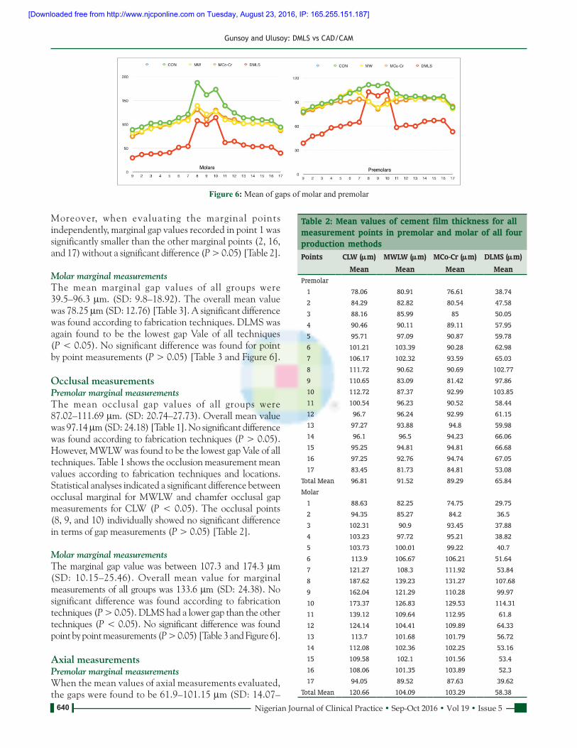
Moreover, when evaluating the marginal points independently, marginal gap values recorded in point 1 was significantly smaller than the other marginal points (2, 16, and 17) without a significant difference (P > 0.05) [Table 2].
Molar marginal measurementsThe mean marginal gap values of all groups were 39.5–96.3 µm. (SD: 9.8–18.92). The overall mean value was 78.25 µm (SD: 12.76) [Table 3]. A significant difference was found according to fabrication techniques. DLMS was again found to be the lowest gap Vale of all techniques (P < 0.05). No significant difference was found for point by point measurements (P > 0.05) [Table 3 and Figure 6].
Occlusal measurementsPremolar marginal measurementsThe mean occlusal gap values of all groups were 87.02–111.69 µm. (SD: 20.74–27.73). Overall mean value was 97.14 µm (SD: 24.18) [Table 1]. No significant difference was found according to fabrication techniques (P > 0.05). However, MWLW was found to be the lowest gap Vale of all techniques. Table 1 shows the occlusion measurement mean values according to fabrication techniques and locations. Statistical analyses indicated a significant difference between occlusal marginal for MWLW and chamfer occlusal gap measurements for CLW (P < 0.05). The occlusal points (8, 9, and 10) individually showed no significant difference in terms of gap measurements (P > 0.05) [Table 2].
Molar marginal measurementsThe marginal gap value was between 107.3 and 174.3 µm (SD: 10.15–25.46). Overall mean value for marginal measurements of all groups was 133.6 µm (SD: 24.38). No significant difference was found according to fabrication techniques (P > 0.05). DLMS had a lower gap than the other techniques (P < 0.05). No significant difference was found point by point measurements (P > 0.05) [Table 3 and Figure 6].
Axial measurementsPremolar marginal measurementsWhen the mean values of axial measurements evaluated, the gaps were found to be 61.9–101.15 µm (SD: 14.07–
Figure 6: Mean of gaps of molar and premolar
Table 2: Mean values of cement film thickness for all measurement points in premolar and molar of all four production methodsPoints CLW (μm) MWLW (μm) MCo‑Cr (μm) DLMS (μm)
Mean Mean Mean MeanPremolar
1 78.06 80.91 76.61 38.74
2 84.29 82.82 80.54 47.58
3 88.16 85.99 85 50.05
4 90.46 90.11 89.11 57.95
5 95.71 97.09 90.87 59.78
6 101.21 103.39 90.28 62.98
7 106.17 102.32 93.59 65.03
8 111.72 90.62 90.69 102.77
9 110.65 83.09 81.42 97.86
10 112.72 87.37 92.99 103.85
11 100.54 96.23 90.52 58.44
12 96.7 96.24 92.99 61.15
13 97.27 93.88 94.8 59.98
14 96.1 96.5 94.23 66.06
15 95.25 94.81 94.81 66.68
16 97.25 92.76 94.74 67.05
17 83.45 81.73 84.81 53.08
Total Mean 96.81 91.52 89.29 65.84
Molar
1 88.63 82.25 74.75 29.75
2 94.35 85.27 84.2 36.5
3 102.31 90.9 93.45 37.88
4 103.23 97.72 95.21 38.82
5 103.73 100.01 99.22 40.7
6 113.9 106.67 106.21 51.64
7 121.27 108.3 111.92 53.84
8 187.62 139.23 131.27 107.68
9 162.04 121.29 110.28 99.97
10 173.37 126.83 129.53 114.31
11 139.12 109.64 112.95 61.8
12 124.14 104.41 109.89 64.33
13 113.7 101.68 101.79 56.72
14 112.08 102.36 102.25 53.16
15 109.58 102.1 101.56 53.4
16 108.06 101.35 103.89 52.3
17 94.05 89.52 87.63 39.62
Total Mean 120.66 104.09 103.29 58.38
[Downloaded free from http://www.njcponline.com on Tuesday, August 23, 2016, IP: 165.255.151.187]

Gunsoy and Ulusoy: DMLS vs CAD/CAM
641Nigerian Journal of Clinical Practice • Sep-Oct 2016 • Vol 19 • Issue 5
25.78). The overall mean value was 88.61 µm (SD: 20.65). Again DLMS had the smallest gap value of all techniques. No significant difference was found among axial, occlusal, and marginal gap measurements for CLW (P < 0.05). Statistical significance was found between DLMS and the other fabrication techniques. DLMS had a lower gap than the other techniques (P < 0.05). Table 1 shows the measurements according to point by point. The occlusal points (6, 7, 11, and 12) individually showed no significant difference in terms of gap measurements (P > 0.05). However, a significant difference was found between axial and marginal for DLMS and MCo‑CR (P < 0.05) [Table 2].
Molar marginal measurementsThe marginal gap value was between 57.9 and 124.6 µm (SD: 10.5–21.18). The overall mean value for marginal measurements of all groups was 100 µm (SD: 18.75). Statistical significance was found between DLMS and the other fabrication techniques. DLMS had a lower gap than the other techniques (P < 0.05). No significant difference was found for point by point measurements (P > 0.05) [Table 3 and Figure 6].
Chamfer measurementsPremolar marginal measurementsWhen the mean values of chamfer measurements evaluated, the gaps were found to be 57.12–91.15 µm (SD: 12.32–24.23). The overall mean value was 81.61 µm (SD: 19.13). Statistical significance was found between DLMS and the other fabrication techniques. DLMS had a
lower gap than the other techniques (P < 0.05). Statistical analyses indicated a significant difference between chamfer and occlusal gap measurements for CLW (P < 0.05) Table 1 shows the measurements according to point by point. The chamfer points (3, 4, 5, 13, 14, and 15) individually showed no significant difference in terms of gap measurements (P > 0.05) [Table 2].
Molar marginal measurementsThe marginal gap value was between 43.9 and 103 µm (SD: 9.8–20.12). The overall mean value for marginal measurements of all groups was 84.15 µm (SD: 19.04). Statistical significance was found between DLMS and the other fabrication techniques. DLMS had a lower gap then the other techniques (P < 0.05). No significant difference was found for point by point measurements (P > 0.05) [Table 3 and Figure 6].
Discussion
The aim of this study was to evaluate the effect of production methods in two models using different fabrication techniques. The results support the acceptance of the null hypothesis as a significant difference was found in the marginal and internal gap among DLMS and the other methods.
Several different methods were described to analyze and evaluate the marginal and internal gap and the fit of the restorations in previous studies.[5,6,8,13‑16]
Table 3: Mean values and standard deviation of molar gap values according to specific measured locations using four fabrication techniquesPremolar/Measured areas Groups N Mean (μm) s.d. Cross statis, P value
CLW (1) 16 96.3 18.92 1‑2
Marginal MWLW (2) 16 89.6 17.14 1‑3 P˃0.05
MCo‑Cr (3) 16 87.6 16.22 2‑3
DLMS (4) 16 39.5 9.8 1‑4, 2‑4, 3‑4 P<0.05
Overall 78.25 16.75
CLW (1) 16 174.3 25.46 1‑2
Occlusal MWLW (2) 16 129.1 21.37 1‑3 P˃0.05
MCo‑Cr (3) 16 123.7 20.18 2‑3
DLMS (4) 16 107.3 10.15 1‑4, 2‑4, 3‑4
Overall 133.6 22.79
CLW (1) 16 124.6 21.18 1‑2
Axial MWLW (2) 16 107.3 20.72 1‑3 P˃0.05
MCo‑Cr (3) 16 110.2 21.64 2‑3
DLMS (4) 16 57.9 10.5 1‑4, 2‑4, 3‑4 P<0.05
Overall 100 19.96
CLW (1) 16 103.0 20.12 1‑2
Chamfer MWLW (2) 16 95.32 19.77 1‑3 P˃0.05
MCo‑Cr (3) 16 94.4 19.67 2‑3
DLMS (4) 16 43.9 9.8 1‑4, 2‑4, 3‑4 P<0.05
Overall 84.15 18.84
Total 99.0 16.42
[Downloaded free from http://www.njcponline.com on Tuesday, August 23, 2016, IP: 165.255.151.187]

Gunsoy and Ulusoy: DMLS vs CAD/CAM
642 Nigerian Journal of Clinical Practice • Sep-Oct 2016 • Vol 19 • Issue 5
Most of the investigators used a single master model and subsequently used working models using impressions.[4‑6,16,17] The shortcoming of this technique is the impact of impression taking on the reproducing of the working models. Moreover, it was impossible to evaluate the models again after a time‑frame. To standardize the dimensions of the models, a different production method from other studies has been used. Whereby distortion may occur when taking impressions and casting was avoided. However, still there are limitations on producing the frameworks or work models.[8]
In this study, the models were fabricated using a 3D printer and used to evaluate the marginal and internal gaps. To the best of our knowledge, no study was performed to fabricate the models in the 3D printer. The usefulness of this method is to overcome the replication of the models and every time the same models fabricated and were used to obtain crowns with different fabrication techniques.
There are many variables tooth preparation design, restoration fabrication techniques, and resin cement on the marginal/internal gap.[18] Moreover, when evaluating these gaps in in vitro conditions, even the measuring points and also measuring techniques can influence the results.[19] However, before making any attempt to evaluate such parameters, the optimally acceptable gap dimensions should be known. Mclean and von Fraunhoder[20] in 1971 concluded that 120 µm can be the acceptable range for the marginal gap while some other studies[21,22] rated the values 100 µm or between 100 and 150 µm is the acceptable gap[23,24] In the meantime 200–300 µm concluded to be the marginal misfit.[25‑27] In the meantime, the measurement points and location yet is important. 17 points in mesiolingual dimension were used to evaluate as many locations as it can be in the models.
This study found 85.97 µm for premolar and 90 µm for molar crowns as overall gap measurements which are in the limit for the good restoration gap. When evaluating the highest marginal, gap was found in CLW (96.81 µm for premolar and 120.66 µm for molar) while the lowest values were found in DLMS (65.84 µm for premolar and 58.39 µm for molar). This result is consistent with other studies as DLMS is the lowest marginal gap and best fit.
Oyague et al . [28] compared CLW and DLMS in implant‑supported restorations and figured out a gap between 30.5 and 50.1 µm for Co‑CR restorations in DLMS. They also found an internal marginal gap in CLW for Cr‑Co to be 78.2–91.8 µm and for Pd‑Au as 45.2–61.7 µm. Quante et al.[14] used silicon replica method and evaluated the marginal and internal gap using laser melting technology. They measured from 10 difference points and found the gap values between 250 and 350 µm using laser melting technology in single crowns while with laser‑sintered Co‑Cr crowns with a mean intergap of 63 µm, which is similar to our findings.
Similarly, Samet et al.[29] investigated the gap values using CAD/CAM and figured out a gap value for CAD/CAM 175 µm. Recently, Örtorp et al.[8] conducted a similar study like ours; they used the same techniques for fabrication of the models. They figured out the DLMS had the lowest mean value below 100 µm followed by MWLW, CLW, and MCo‑Cr. Our results are consistent with their results as DLMS had the lowest value followed by MCoCr, MWLW, and CLW. The values for MWLW, MCo‑Cr, and DLMS were under the 100 µm which can be acceptable for a good marginal fit. However, it should be stated that this study was performed on three‑unit fixed dental prosthesis while our study conducted on single crowns. For single tooth restorations, it was stated that 120 µm is an acceptable marginal gap which our results were below for all techniques.[20]
For CAD/CAM fabrication restorations, there are only few studies about single crown restorations. Recently, all ceramic onlay were investigated using CAD/CAM technology and figured out an internal gap value between 80 and 85 µm.[30,31] In the recent study by Guess et al.[13] found a CAD/CAM‑fabricated an in‑plane switching e.max CAD onlay restorations with a mean gap of 54 µm. Moreover in the literature, the values between 50 and 60 µm were also reported by some studies for CAD/CAM‑fabricated restorations.[13,32‑35] Our results indicated the values for 89.29 µm (premolar) – 104.09 µm (molar) for MWLW and MCo‑Cr that fabricated CAD/CAM. This result is in line with some results[30,31] but larger than Guess et al.’s study[13] which can be interpreted as the different preparation designs and also the material itself.
The fabrication using different techniques indicated no marginal gap difference within the occlusal surface (P > 0.05) as in our study. However, significant differences were found for premolar single crowns for other locations (axial, marginal, and chamfer) [Table 1]. The marginal discrepancies can be explained by the fact that the restorations margin were placed by 1 mm above the cementoenamel junction and while having the wax modeling stage or CAD/CAM design these areas are tended to have more distortion. Thus, the marginal gap values can be affected by the techniques.[12,13]
For axial measurements, Beuer et al.[5] figured out a mean gap 71 µm for ceramic restorations using CAD/CAM while Bindl and Mörman[36] found reported an axial gap 103 µm for Zirconia. Kahramanoglu and Kulak‑Özkan[37] found their implant supported fixed dental prosthesis and figured a gap value for axial between 117.21 and 203.26 µm. In this study, we found 61.9–101.15 µm axial gap value for premolar and 57.9–124.6 µm for molar single crowns. These results are also similar to previous studies. However, it should also be stated that this study was based on Single Cr‑Co crowns. No attempt to compare these results with the previous studies since no applicable data could be found.
[Downloaded free from http://www.njcponline.com on Tuesday, August 23, 2016, IP: 165.255.151.187]
Gunsoy and Ulusoy: DMLS vs CAD/CAM
643Nigerian Journal of Clinical Practice • Sep-Oct 2016 • Vol 19 • Issue 5
The measurement of occlusal gap showed the highest values for both premolar and molar single crowns. Previous studies also found similar results on this.[14‑37] As indicated in a previous study,[37] the occlusal gaps were found to be higher because of occlusal reduction of burnout copings.
The main limitation of this study that only mesiodistal measurements were made, but bucca l ‑ l ingua l measurements were not done. Another limitation can be when the cross sections examined in the microscope, some of the areas on model‑cement border occurred blurry due to the structure of polyamide. In order to avoid this limitation, we determined as many points as we can [Figure 5] and also made five measurements from that point and repeated all measurements for intraobserver confidence.
Conclusion
In conclusion, within the limitation of this study, the best fit was in DLMS group, followed by CAD/CAM (MWLW, MCo‑Cr) and the conventional method. The best fit was found in marginal; the larger gap was found in occlusal. All fabrication techniques used in this study can be used for single crowns; however, because of speed‑up production and for cost effective DLMS should be used for single crown manufacturing.
Financial support and sponsorshipNil.
Conflicts of interestThere are no conflicts of interest.
References
1. TomanM,ToksavulS,SchmageP,NergizI.Influenceofmarginalpreparationtypeanddifferentceramicmaterialonthemarginalfitofall‑ceramiccrowns.SUDishekimFakDerg2009;18:7‑12.[InTurkish,Englishabstract].
2. UshiwataO,MoraesJV.Methodformarginalmeasurementsofrestorations:Accessorydevicefortoolmakersmicroscope.JProsthetDent2003;83:362‑6.
3. YeoIS,YangJH,LeeJB. In vitro marginalfitofthreeall‑ceramiccrownsystems.JProsthetDent2003;90:459‑64.
4. SongTJ,KwonTK,YangJH,HanJS,LeeJB,KimSH,et al.Marginalfitofanterior3‑unitfixedpartialzirconiarestorationsusingdifferentCAD/CAMsystems.JAdvProsthodont2013;5:219‑25.
5. Beuer F,NaumannM,GernetW, Sorensen JA. Precisionof fit:Zirconiathree‑unitfixeddentalprostheses.ClinOralInvestig2009;13:343‑9.
6. UcarY,AkovaT,AkyilMS,BrantleyWA.Internalfitevaluationofcrownsprepared using a newdental crown fabrication technique: Laser‑sinteredCo‑Crcrowns.JProsthetDent2009;102:253‑9.
7. TakahashiT,Gunne J. Fit of implant frameworks:An in vitro comparisonbetweentwofabricationtechniques.JProsthetDent2003;89:256‑60.
8. Örtorp A, Jönsson D, Mouhsen A, Vult von Steyern P. The fit ofcobalt‑chromium three‑unit fixed dental prostheses fabricated withfour different techniques: A comparative in vitro study. Dent Mater2011;27:356‑63.
9. IseriU,OzkurtZ,KazazogluE.Shearbondstrengthsofveneeringporcelain
tocast,machinedandlaser‑sinteredtitanium.DentMaterJ2011;30:274‑80.10. WangRR,FentonA.Titaniumforprosthodonticapplications:Areviewof
theliterature.QuintessenceInt1996;27:401‑8.11. NelsonSJ,AshMMJr.Wheeler’sDentalAnatomy,PhysiologyandOcclusion.
9thed.St.Louis:ElsevierSaunders;2010.p.141‑55,171‑88.12. KuniiJ,HottaY,TamakiY,OzawaA,KobayashiY,FujishimaA,et al.Effect
ofsinteringonthemarginalandinternalfitofCAD/CAM‑fabricatedzirconiaframeworks.DentMaterJ2007;26:820‑6.
13. GuessPC,VagkopoulouT,ZhangY,WolkewitzM,StrubJR.MarginalandinternalfitofheatpressedversusCAD/CAMfabricatedall‑ceramiconlaysafterexposuretothermo‑mechanicalfatigue.JDent2014;42:199‑209.
14. QuanteK,LudwigK,KernM.Marginal and internalfitofmetal‑ceramiccrowns fabricated with a new laser melting technology. DentMater2008;24:1311‑5.
15. VojdaniM,TorabiK,FarjoodE,KhalediA.ComparisonthemarginalandinternalfitofmetalcopingscastfromwaxpatternsfabricatedbyCAD/CAMandconventionalwaxuptechniques.JDent(Shiraz)2013;14:118‑29.
16. SuleimanSH,VultvonSteyernP.Fracturestrengthofporcelain fused tometalcrownsmadeofcast,milledorlaser‑sinteredcobalt‑chromium.ActaOdontolScand2013;71:1280‑9.
17. BlackmanR,BaezR,BarghiN.Marginalaccuracyandgeometryofcasttitaniumcopings.JProsthetDent1992;67:435‑40.
18. NawaflehNA,MackF,EvansJ,MackayJ,HatamlehMM.AccuracyandreliabilityofmethodstomeasuremarginaladaptationofcrownsandFDPs:Aliteraturereview.JProsthodont2013;22:419‑28.
19. KeshvadA,Hooshmand T, Asefzadeh F, Khalilinejad F, AlihemmatiM,VanNoortR.Marginalgap,internalfit,andfractureloadofleucite‑reinforcedceramic inlays fabricated byCEREC inLab and hot‑pressed techniques.JProsthodont2011;20:535‑40.
20. McLeanJW,vonFraunhoferJA.Theestimationofcementfilmthicknessbyan in vivo technique.BrDentJ1971;131:107‑11.
21. BoeningKW,WalterMH,ReppelPD.Non‑casttitaniumrestorationsinfixedprosthodontics.JOralRehabil1992;19:281‑7.
22. FranssonB,OiloG,GjeitangerR.Thefitofmetal‑ceramiccrowns,aclinicalstudy.DentMater1985;1:197‑9.
23. SuárezMJ,GonzálezdeVillaumbrosiaP,PradíesG,LozanoJF.ComparisonofthemarginalfitofProceraAllCeramcrownswithtwofinishlines.IntJProsthodont2003;16:229‑32.
24. ColiP,KarlssonS.Fitofanewpressure‑sinteredzirconiumdioxidecoping.IntJProsthodont2004;17:59‑64.
25. SutherlandJK,LoneyRW,JarotskicTJ.Marginaldiscrepancyofceramiccrownswithredesignedimplantcomponents.JProsthetDent1996;75:540‑4.
26. OstlundLE.Cavitydesignandmathematics:Theireffectongapsatthemarginsofcastrestorations.OperDent1985;10:122‑37.
27. StappertCF,DennerN,GerdsT,StrubJR.Marginaladaptationofdifferenttypesofall‑ceramicpartialcoveragerestorationsafterexposuretoanartificialmouth.BrDentJ2005;199:779‑83.
28. Oyagüe RC, Sánchez‑Turrión A, López‑Lozano JF, Suárez‑García MJ.Vertical discrepancy andmicroleakage of laser‑sintered and vacuum‑castimplant‑supported structures lutedwith different cement types. JDent2012;40:123‑30.
29. SametN, Resheff B,Gelbard S, SternN.ACAD/CAM system for theproduction ofmetal copings for porcelain‑fused‑to‑metal restorations.JProsthetDent1995;73:457‑63.
30. DenissenH,DozicA,vanderZelJ,vanWaasM.Marginalfitandshort‑termclinicalperformanceofporcelain‑veneeredCICERO,CEREC,andProceraonlays.JProsthetDent2000;84:506‑13.
31. Stappert CF, Chitmongkolsuk S, SilvaNR, AttW, Strub JR. Effect ofmouth‑motion fatigue and thermal cycling on themarginal accuracy ofpartialcoveragerestorationsmadeofvariousdentalmaterials.DentMater2008;24:1248‑57.
32. BanksRG.Conservativeposteriorceramicrestorations:Aliteraturereview.JProsthetDent1990;63:619‑26.
33. InokoshiS,VanMeerbeekB,WillemsG,LambrechtsP,BraemM,VanherleG.MarginalaccuracyofCAD/CAMinlaysmadewiththeoriginalandtheupdatedsoftware.JDent1992;20:171‑7.
34. MörmannWH,SchugJ.GrindingprecisionandaccuracyoffitofCEREC2CAD‑CIMinlays.JAmDentAssoc1997;128:47‑53.
[Downloaded free from http://www.njcponline.com on Tuesday, August 23, 2016, IP: 165.255.151.187]

Gunsoy and Ulusoy: DMLS vs CAD/CAM
644 Nigerian Journal of Clinical Practice • Sep-Oct 2016 • Vol 19 • Issue 5
35. MartinN,JedynakiewiczNM.InterfacedimensionsofCEREC‑2MODinlays.DentMater2000;16:68‑74.
36. BindlA,MörmannWH.Fitof all‑ceramicposteriorfixedpartial dentureframeworksin vitro.IntJPeriodonticsRestorativeDent2007;27:567‑75.
37. Kahramanoglu E, Kulak‑ÖzkanY.The effect of different restorative andabutmentmaterialsonmarginalandinternaladaptationofthree‑unitcantileverimplant‑supported fixed partial dentures:An in vitro study. J Prosthodont2013;22:608‑17.
[Downloaded free from http://www.njcponline.com on Tuesday, August 23, 2016, IP: 165.255.151.187]