Embed Size (px)
Citation preview
Int. J. Communications, Network and System Sciences, 2009, 2, 720-731 doi:10.4236/ijcns.2009.28083 blished Online November 2009 (http://www.SciRP.org/journal/ijcns/).
Copyright © 2009 SciRes. IJCNS
Pu
Evaluation of Network Stack Optimization Techniques for Wireless Sensor Networks
Jaein JEONG Computer Science Division, UC Berkeley, Berkeley, California, USA
Email: [email protected] Received August 19, 2009; revised September 20, 2009; accepted October 10, 2009
Abstract
We present a network stack implementation for a wireless sensor platform based on a byte-level radio. The network stack provides error-correction code, multi-channel capability and reliable communication for a high packet reception rate as well as a basic packet-level communication interface. In outdoor tests, the packet reception rate is close to 100% within 800 ft and is reasonably good up to 1100 ft. This is made possible by using error correction code and a reliable transport layer. Our implementation also allows us to choose a fre-quency among multiple channels. By using multiple frequencies as well as a reliable transport layer, we can achieve a high packet reception rate by paying additional retransmission time when collisions increase with additional sensor nodes.
Keywords: Wireless Sensors, Network Stack, Error Correction Code, Reliable Transport, Multi Channel
1. Introduction In wireless sensor networks, it is desirable to have sensor nodes communicate without packet loss allowing infor-mation from a sensor node to be transferred reliably. In reality, however, sensor nodes suffer different levels of packet loss due to signal attenuation and multi-path ef-fect [1–3]. In this paper, we take a practical approach to address this problem. We implement a network stack as an experiment vehicle based on a byte-level radio, the CC1000 transceiver [4]. Besides the basic packet-level communication, the network stack provides additional functionality for performance improvement such as er-ror-correction code, retransmission and channel diver-sity. Based on the network stack we have implemented, we have evaluated how this extended functionality im-proves communication performance. Our network stack has reasonable performance in an outdoor environment with the packet reception rate close to 100% within an 800 ft range. We have found that error-correction code, retransmission and channel diversity improves this per-formance even further. For error-correction code, we have used SECDED (Single-Error Correction and Dou-ble-Error Detection) code [5,6]. Using SECDED code improved the packet reception rate, but it was not effec-tive when packets were completely lost due to the multi- path effect. Retransmission was effective in reducing
packet losses from the multi-path effect and contention from traffic. We also saw that using multiple radio channels was very effective in reducing collisions when multiple senders burst packets.
The rest of this paper is organized in the following way: Section 2 overviews background and related work; Section 3 describes the design principles of our network stack; Section 4 empirically evaluates our network stack and Section 5 concludes this paper. 2. Background and Related Work TinyOS provides communication capability using multi-ple layers like other networked systems: application, transport, network, and link layer. An application sees the radio as a service interface through which it can send and receive data in fixed sized packets. The transport layer provides best effort delivery and process-to-process communication. The network layer provides a routing tree. The link layer converts a packet to and from the byte data and interacts with the underlying radio chip. Since the link layer is so closely coupled with the radio chip, writing a network stack for a new platform usually requires rewriting the link layer.
Our project is based on some earlier works. Hill wrote a preliminary version of a network stack for the CC1000
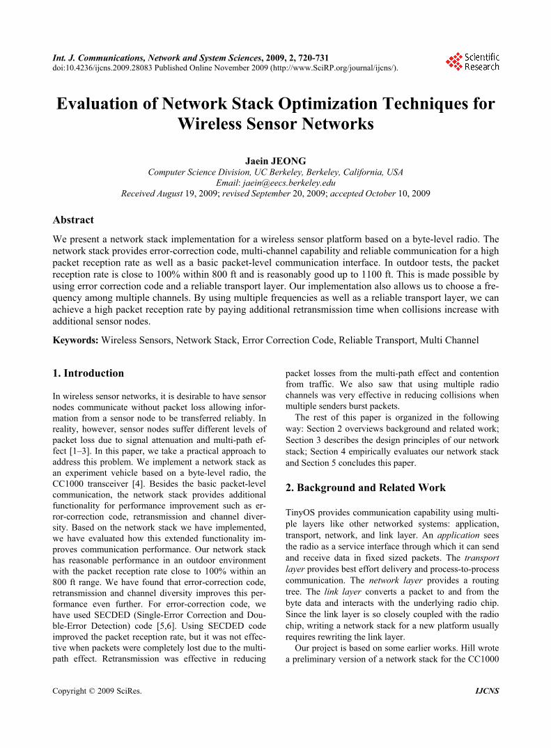
J. JEONG 721 radio supporting Active Message number multiplexing and packet framing [7]. The CC1000 can operate in one of three frequency bands (433MHz, 866MHz and 900 MHz) and each band requires different values for exter-nal components and initialization parameters. The choice of frequency band is determined by the coverage and the number of legally usable channels: 900MHz is preferred for its relatively large selection of channels and 433MHz for its longer range. Hill initially wrote a network stack for the CC1000 radio in the 900MHz range and Cross-bow technology modified it to support the 433MHz range. From the earlier work done by Hill and Crossbow technology, we found some room for improvement: 1) supporting error correction code to protect data from transient errors, 2) utilizing multiple channels of the CC1000 radio chip, 3) supporting reliable communica-tion. 3. Design In this section, we describe mechanism and design phi-losophy of our network stack for the Mica2dot platform [8] that is based on a byte-level radio transceiver CC1000 radio chip and the ATMega103L microcontrol-ler [9], illustrated in Figure 1. First, we describe how we provide byte-level data and configuration interfaces (SpiByteFifoC and ChipconC modules in Figure 1) to
(a) Mica2dot node – front and back
Application
ReliableComm
GenericComm
RadioCRCPacket
ChannelMonC
Radio
SpiByteFifoC
SecDedEncoding
Packets
Bytes
Bits
Retransmission using acknowledgement
Multiplexing messages for process-to-process communication
Packet marshalling layer betweenGenericComm and RFCommC
Packet decomposition and reassembly
Encoding/decoding data for error correction
Configuration interface to CC1000 radio
RFCommC Calculates CRC and filters out incoming packets with wrong CRC
ChipconC Byte-data interface to CC1000 radio
(b) Mica2dot network stack and description of its layers
abstract h
e physical level,
Figure 1. Mica2dot and its network stack.
the low-level interface of the CC1000 radio witgeneric byte-level interfaces. Second, we describe how we provide a packet-level interface for the CC1000 radio (ChannelMonC module). Third, we describe how we provide error-correction capability to protect data from transient errors (SecDedEncoding module). Fourth, we describe how we provide an interface to utilize the diver-sity of multiple radio channels (ChipconC module). Fifth, we describe how we support reliable communica-tion using retransmission (ReliableComm module).
.1. Abstracting Radio Hardware 3
) Byte-level data interface: While at th1the ATMega103L microcontroller communicates with the CC1000 radio in bits over two serial pins, it provides a byte-level interface through the SPI (Serial Peripheral Interface) registers: SPSR, SPDR and SPCR. SPSR (SPI Status Register) can be used to check
whether there is an incoming byte or not. The most sig-nificant bit (bit 7) of the SPSR becomes high when there is an incoming byte in the buffer, low otherwise. The CC1000 radio can be switched between send and receive mode by changing the data direction of the data pin (bit-3 of port B of ATMega103L microcontroller). SPDR (SPI Data Register) is a byte buffer, which
assembles either outgoing or incoming bits into a byte before reading or writing data to and from the CC1000 radio. When incoming bits are assembled into a byte, the ATMega103L microcontroller triggers SIG_SPI interrupt as well as setting bit 7 of the SPSR. This allows incom-ing data for the CC1000 to be efficiently processed using an interrupt instead of polling. One note is that only a send or a receive can be done at any time because the CC1000 radio has only a single buffer. SPCR (SPI Control Register) can be used to enable
or disable interrupts. The SPI clock interrupt is triggered when SPCR is set to 0xc0, and is disabled when set to 0x40. Finally, data should be read or written at the same rate with that of the external device. The CC1000 radio is synchronized to the ATMega103L microcontroller thro- ugh the SPI clock. The clock triggers an output pin of the microcontroller (bit-1 of port B) to the data clock pin of the radio chip (SPI CLK).
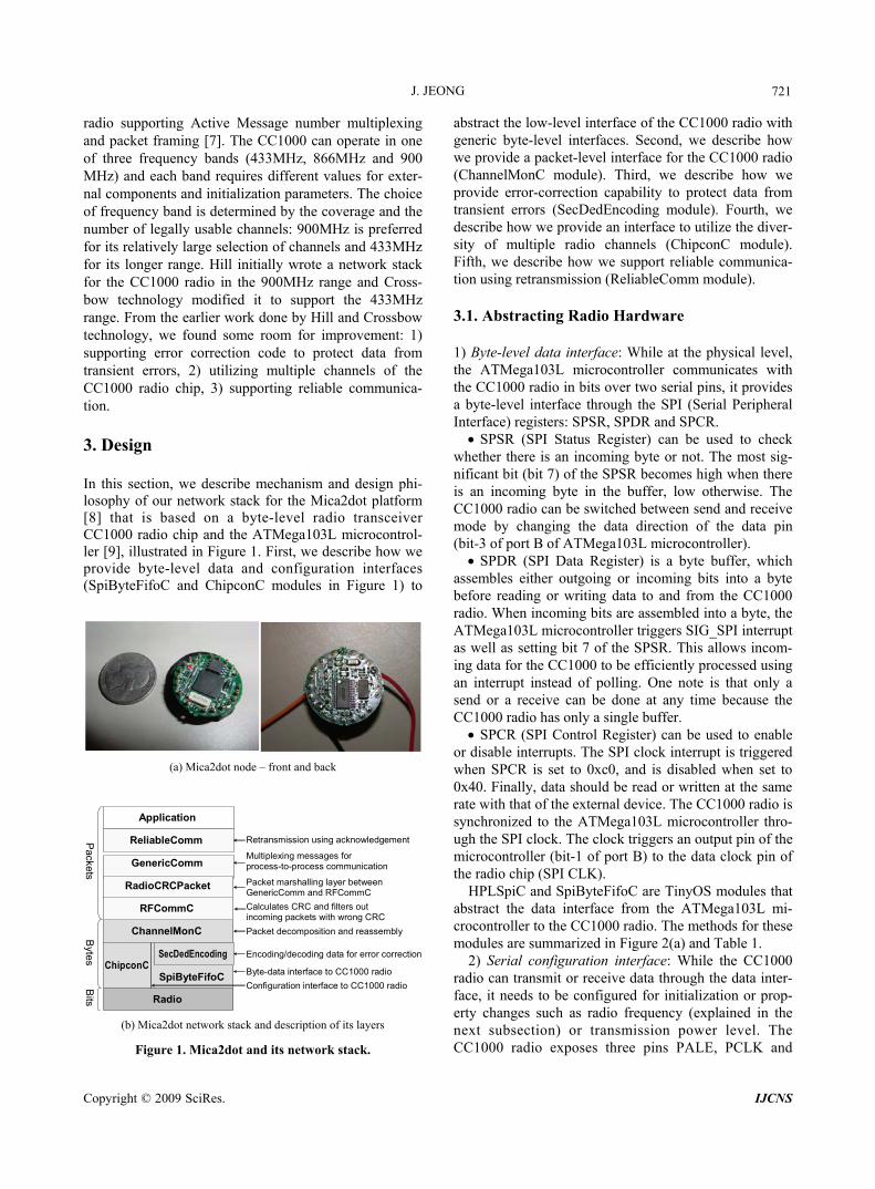
HPLSpiC and SpiByteFifoC are TinyOS modules that abstract the data interface from the ATMega103L mi-crocontroller to the CC1000 radio. The methods for these modules are summarized in Figure 2(a) and Table 1.
2) Serial configuration interface: While the CC1000 radio can transmit or receive data through the data inter-face, it needs to be configured for initialization or prop-erty changes such as radio frequency (explained in the next subsection) or transmission power level. The CC1000 radio exposes three pins PALE, PCLK and
Copyright © 2009 SciRes. IJCNS
J. JEONG
Copyright © 2009 SciRes. IJCNS
722
en
ab
leln
tr()
ntr
()
yte
()
mp
ty()
() ) e()
()
ad
y()
) () r() ) )
dis
ab
lel
wri
teB
isB
ufE
rxM
od
e
txM
od
e(
rea
dB
yt
initS
lave
da
taR
e
Init(
)
tun
e()
txm
od
e(
rxm
od
e
sle
ep
()
aw
ake
()
off(
)
on
()
rf_
po
we
rf_
pw
up
(
rf_
pw
dn
(
enab
le_i
ntr(
)
disa
ble_
intr(
)
writ
e_by
te()
is_e
mpt
y()
rxm
ode(
)
txm
ode(
)
read
_byt
e()
Init(
)
writ
e()
read
()
SpiByteFifoc(for data transfer) ChipconC(for configuration)
HPLSpiC HPLChipconC
SPCR SPDR SPSR Port B bit 3
ATMega103L Micro-controller Port bit 6 Port D bit 5 Port D bit 7
PCLK PALE PDATA CC1000 RadioSPI CLK SPI data
0xc
to e
nabl
eIn
terru
pt, 0
x40
to d
isabl
e it
Rea
d or
writ
ea
byte
Bit-7
is
‘1’
if th
ere
is in
com
ing
byte
‘0
’ oth
erwi
se
‘1’ fo
r txm
ode
‘0’ fo
r rxm
ode
Softw
are
Gen
erat
e Cl
k
Com
man
d (‘0
’) or
dat
a M
ode
(‘1’)
Com
man
d or
da
ta b
yte
in sy
nc w
ith
P CLK
(a) Hardware abstraction for CC1000 radio – SpiByteFifoC and ChipconC modules provide higher-level abstraction over CC1000 radio hardware
(b) Bit sequence for accessing CC1000 control registers – i) write a byte, ii) read a b e yt
(c) Waveform of CC1000 in spectrum analyzer – i) correctly configured, ii) misconfigured. Notice that the peak is over 10dB higher when the ra o is
Abstracting radio hardware.
DATA for this purpose as shown in Figure 2(a). These 3) Using multiple channels: The CC1000 radio allows
dicorrectly configured compared to when it is misconfigured.
Figure 2.
Ppins are mapped to data port pins (port D bit 5, 6 and 7). By setting or clearing these pins, the microcontroller can send a sequence of bits (control register address, a byte of data and a bit representing whether the operation is write or read as it is shown in Figure 2(b). This is im-plemented as init(), write() and read() in the HPLChip-conC module (Table 2). The ChipconM module imple-ments high level functions such as setting the radio fre-quency or transmission power using these primitives.
us to select a channel at run time among a number of fre-quencies. The purpose of selecting channels is to reduce any interference from neighboring sensor nodes or other wireless devices. For the CC1000 radio chip to operate at a specific frequency, it needs to be configured with the correct frequency words and clock divisor byte. CC1000 transmits and receives at different frequencies and these frequencies are represented by two 24-bit frequency words. These frequencies are generated by dividing the
J. JEONG 723
terf
Method Description
Table 1. Byte-level data in ace to the CC1000 radio.
HPLSpiC
HPLSpi. enable_intr() Enables SPI clock interrupt (sets SPCR to 0xC0)
HPLSpi. dis Disables SPI clock in CR to 0x40)
‘0’ otherwise
rtB as ‘1’)
able_intr() terrupt (sets SP
HPLSpi. write_byte() Writes a byte (writes a byte to SPDR)
HPLSpi. read_byte() Reads a byte (reads a byte from SPDR)
HPLSpi. is_empty() Bit-7 is ‘1’ if there is an incoming byte,
HPLSpi. txmode() Switches to transmit mode (sets bit-3 of Po
HPLSpi. rxmote() Switches to transmit mode (sets bit-3 of PortB as ‘0’)
SpiByteFifoC
Method Description
SpiByteFifo. initSlave() Initializes the SPI registers
SpiByteFifo. () Called when there is an e dataReady incoming byt
SpiByteFifo. enableIntr() Calls HPLSpi.enable_intr( )
SpiByteFifo. diableIntr() Calls HPLSpi.diable_intr( )
SpiByteFifo. writeByte() Calls HPLSpi.write_byte( )
SpiByteFifo. readByte() Calls HPLSpi.read_byte( )
SpiByteFifo. isBufEmpty() Calls HPLSpi.is_empty( )
SpiByteFifo. txMode() Calls HPLSpi.txmode( )
SpiByteFifo. rxMode() Calls HPLSpi.rxmode( )
Table 2. Serial configuration interface to the CC1000 radio.
HPLChipconC
Method Description
HPLChipcon.init() Initializes CC1000 configuration registers
HPLChipcon. ite() Writes a byte to the CC1000 register with the given 7-bit address
-bit address
wr
HPLChipcon.read() Reads a byte from the CC1000 register with the given 7
ChipconM
Method Description
Chipcon. init() Initializes CC1000 configuration register radio frequency to the given value s and tunes the
Chipcon. tune() Tunes the radio frequency to the given value
)
leep mode
() adio
p() for the CC1000 radio
adio
Chipcon. txmode( Sets the CC1000 in transmit mode
Chipcon. rxmode() Sets the CC1000 in receive mode
Chipcon. sleep() Puts the CC1000 in the sleep mode
Chipcon. awake() Awakes the CC1000 radio from the s
Chipcon. off() Turns off the CC1000 radio
Chipcon. on() Turns on the CC1000 radio
Chipcon. rf_power Sets the transmit power for the CC1000 r
Chipcon. rf_pwu Increments the transmit power
Chipcon. rf_pwdn() Decrements the transmit power for the CC1000 r
Copyright © 2009 SciRes. IJCNS
J. JEONG 724
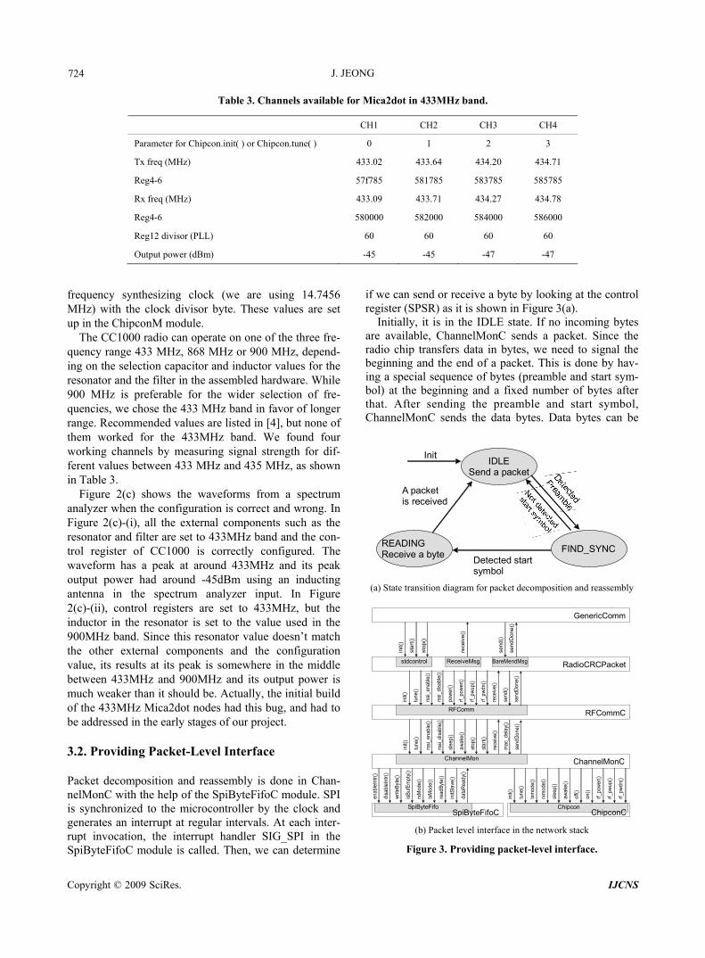
33MHz band.
H2 CH3 CH4
Table 3. Channels available for Mica2dot in 4
CH1 C
Parameter for Chipco 3 n.init( ) or Chipcon.tune( ) 0 1 2
Tx freq (MHz) 433.02 433.64 434.20 434.71
Reg4-6 57f 5817 5837 5857
433. 433. 434. 434.
or (PLL)
Bm)
785 85 85 85
Rx freq (MHz) 09 71 27 78
Reg4-6 580000 582000 584000 586000
Reg12 divis 60 60 60 60
Output power (d -45 -45 -47 -47
frequency sy (we are using 14.7456 MHz) with the clock hese values are set
p in the ChipconM module.
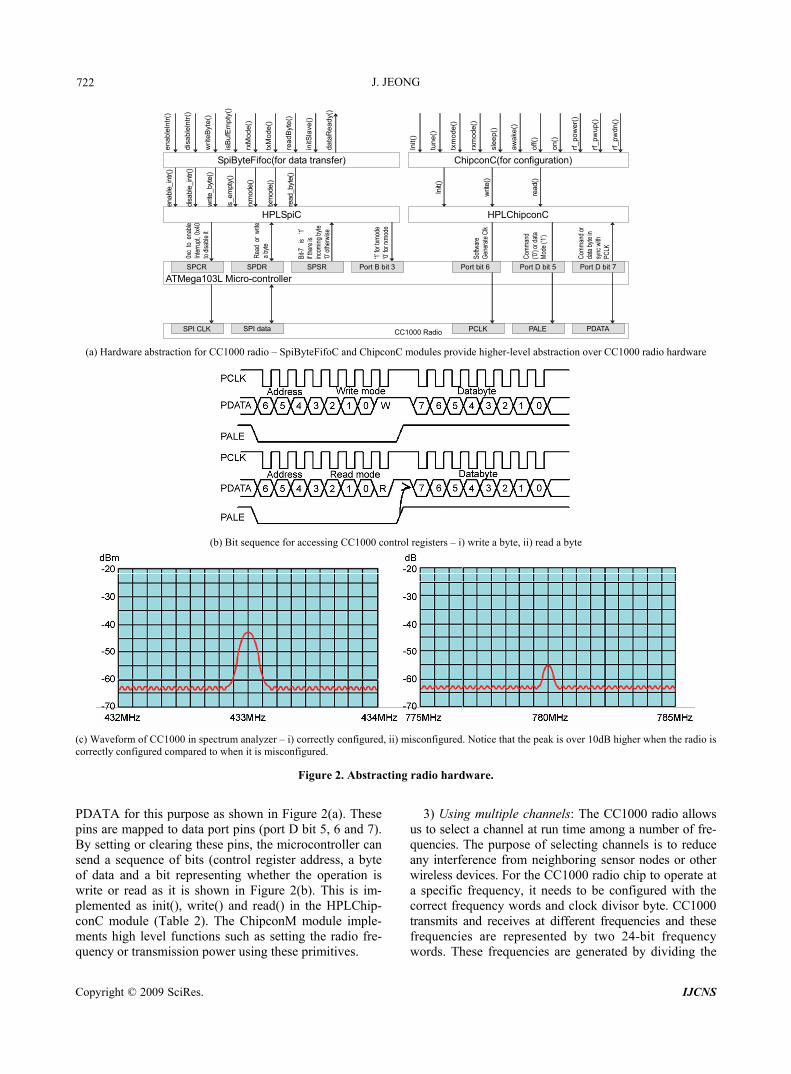
acket decomposition and reassembly is done in Chan-odule. SPI
he clock and
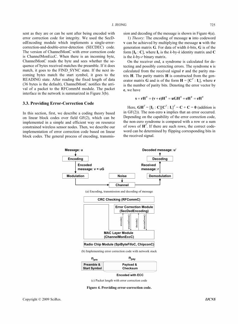
e can se receive a byte by looking at the control ister (SP as it is s n in Figu ).
Initially, it is in the IDLE state. If no incoming bytes
nthesizing clock divisor byte. T
uThe CC1000 radio can operate on one of the three fre-
quency range 433 MHz, 868 MHz or 900 MHz, depend-ing on the selection capacitor and inductor values for the resonator and the filter in the assembled hardware. While 900 MHz is preferable for the wider selection of fre-quencies, we chose the 433 MHz band in favor of longer range. Recommended values are listed in [4], but none of them worked for the 433MHz band. We found four working channels by measuring signal strength for dif-ferent values between 433 MHz and 435 MHz, as shown in Table 3.
Figure 2(c) shows the waveforms from a spectrum analyzer when the configuration is correct and wrong. In Figure 2(c)-(i), all the external components such as the resonator and filter are set to 433MHz band and the con-trol register of CC1000 is correctly configured. The waveform has a peak at around 433MHz and its peak output power had around -45dBm using an inducting antenna in the spectrum analyzer input. In Figure 2(c)-(ii), control registers are set to 433MHz, but the inductor in the resonator is set to the value used in the 900MHz band. Since this resonator value doesn’t match the other external components and the configuration value, its results at its peak is somewhere in the middle between 433MHz and 900MHz and its output power is much weaker than it should be. Actually, the initial build of the 433MHz Mica2dot nodes had this bug, and had to be addressed in the early stages of our project. 3.2. Providing Packet-Level Interface PnelMonC with the help of the SpiByteFifoC m
synchronized to the microcontroller by tisgenerates an interrupt at regular intervals. At each inter-rupt invocation, the interrupt handler SIG_SPI in the SpiByteFifoC module is called. Then, we can determine
are available, ChannelMonC sends a packet. Since the radio chip transfers data in bytes, we need to signal the beginning and the end of a packet. This is done by hav-ing a special sequence of bytes (preamble and start sym-bol) at the beginning and a fixed number of bytes after that. After sending the preamble and start symbol, Ch
if wreg
nd or SR) how re 3(a
annelMonC sends the data bytes. Data bytes can be
IDLE Send a packet
READING Receive a byte
Init
A packet is received
FIND_SYNCDetected start symbol
(a) State transition diagram for packet decomposition and reassembly
stdcontrol ReceiveMsg BareMendMsg
RFComm
ChannelMon
SpiByteFifo Chipcon
GenericComm
RadioCRCPacket
RFCommC
ChannelMonC
ChipconCSpiByteFifoC
init(
)
sta
rt()
sto
p()
rece
ive
()
send
()
send
Don
e()
init(
)
une(
)
ssi_
enab
l
ssi_
disa
bl
pow
er()
_pow
er()
_pw
up()
_pw
dn()
ceiv
e()
end(
)
endD
one(
t re(
)
re(
)
rf rf
rf
re s s)
init(
)
tune
()
rssi
_ena
ble(
)
rssi
_dis
able
()
slee
p()
awak
e()
stop
()
star
t()
rece
ive(
)
mac
_del
ay()
send
Don
e()
enab
leIn
tr()
disa
bleI
ntr(
)
writ
eByt
e()
isB
ufE
mpt
y()
rxM
ode(
)
txM
ode(
)
read
Byt
e()
initS
lave
()
data
Rea
dy()
init(
)
tune
()
txm
ode(
)
rxm
ode(
)
slee
p()
awak
e()
off()
on()
rf_po
wer
()
rf_pw
up()
rf_pw
dn()
(b) Packet level interface in the network stack
Figure 3. Providing packet-level interface.
Copyright © 2009 SciRes. IJCNS
J. JEONG
725
sent as they are or can be sent after being encoded with error correction code for integrity. We used the SecD-edEncoding module which implements a single-error- correction-and-double-error-detection (SECDEC) code. The version of ChannelMonC with error correction code is ChannelMonEccC. When there is an incoming byte, ChannelMonC reads the byte and sees whether the se-quence of bytes received matches the preamble. If it does match, it goes to the FIND_SYNC state. If the next in-coming bytes match the start symbol, it goes to the READING state. After reading the fixed length of data (36 bytes is the default), ChannelMonC notifies the arri-val of a packet to the RFCommM module. The packet interface in the network is summarized in Figure 3(b). 3.3. Providing Error-Correction Code In this se ry based on linea can be
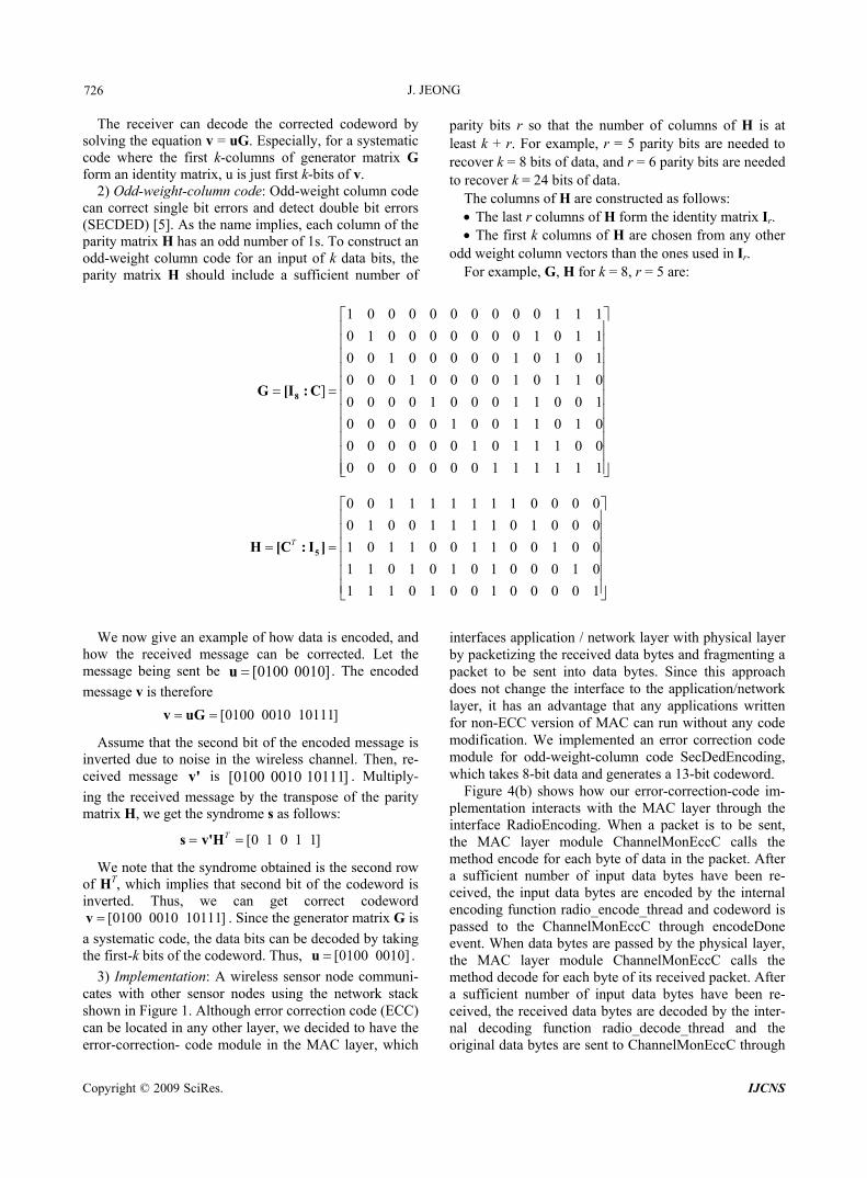
on and decoding of the message is shown in Figure 4(a). o codeword
can be achieved by multiplying the message u with the
er
gnal.
ction, first, we describe a coding theor block codes over field GF(2), which
implemented in a simple and efficient way on resource constrained wireless sensor nodes. Then, we describe our implementation of error correction code based on linear block codes. The general process of encoding, transmis-
Message: u
si1) Theory: The encoding of message u int
vgeneration matrix G. For data of width k-bits, G is of the form [Ik : C], where Ik is the k-by-k identity matrix and C is the k-by-r binary matrix.
On the receiver end, a syndrome is calculated for de-tecting and possibly correcting errors. The syndrome s is calculated from the received signal r and the parity ma-trix H. The parity matrix H is constructed from the gen-
ator matrix G and is of the form H = [CT : Ir], where r is the number of parity bits. Denoting the error vector by e, we have
T T T T Ts rH (v e)H uGH eH eH
Here, GHT = [Ik : C][CT : Ir]T = C + C = 0 (addition is
in GF(2)). The non-zero s implies that an error occurred. Depending on the capability of the error correction code, the non-zero syndrome is compared with a row or a sum of rows of HT. If there are such rows, the correct code-word can be determined by flipping corresponding bits in the received si
Encoding
Modulation
Channel
Noise Demodulation
Decoding
Decoded message: u’
Received message: r
Encoded message: v = uG
(a) Encoding, transmission and decoding of message
Error Correction Module(SecDedEncoding)
deco
deD
one(
)
enco
de()
enco
deD
one(
)
deco
de()
Radio Chip Module (SpiByteFifoC, ChipconC)
MAC Layer Module (ChannelMonEccC)MAC Layer Module (ChannelMonEccC)
CRC Checking (RFCommC)
(b) Implementing error correction code with network stack
Preamble & Start Symbol
Payload & Checksum
nprenpay
Encoded with ECC (c) Packet length with error correction code
Figure 4. Providing error-correction code.
Copyright © 2009 SciRes. IJCNS
J. JEONG 726
The receiver can decode the corrected codeword by
solving the equation v = uG. Especially, for a systematic code where the first k-columns of generator matrix G form an identity matrix, u is just first k-bits of v.
2) Odd-weight-column code: Odd-weight column code can correct single bit errors and detect double bit errors (SECDED) [5]. As the name implies, each column of the parity matrix H has an odd number of 1s. To construct an odd-weight column code for an input of k data bits, the parity matrix H should include a sufficient number of
parity bits r so that the number of columns of H is at least k + r. For example, r = 5 parity bits are needed to recover k = 8 bits of data, and r = 6 parity bits are needed to recover k = 24 bits of data.
The columns of H are constructed as follows: The last r columns of H form the identity matrix Ir. The first k columns of H are chosen from any other
odd weight column vectors than the ones used in Ir. For example, G, H for k = 8, r = 5 are:
We now give an example of how data is encoded, and how the received message can be corrected. Let the message being sent be . The encoded
message v is therefore
Assume that the second bit of the encoded message is inverted due to noise in the wireless channel. Then, re-ceived message is . Multiply-
ing the received message by the transpose of the parity matrix H, we get the syndrome s as follows:
We note that the syndrome obtained is the second row of HT, which implies that second bit of the codeword is inverted. Thus, we can get correct codeword
. Since the generator matrix G is
data bits can be decoded by taking ord. Thus,
ugh error correcter layer, we decidodule in the MAC layer, which
interfaces application / network layer with physical layer by packetizing the received data bytes and fragmenting a packet to be sent into data bytes. Since this approach does not change the interface to the application/network layer, it has an advantage that any applications written for non-ECC version of MAC can run without any code modification. We implemented an error correction code module for odd-weight-column code SecDedEncoding, which takes 8-bit data and generates a 13-bit codeword.
Figure 4(b) shows how our error-correction-code im-plementation interacts with the MAC layer through the interface RadioEncoding. When a packet is to be sent, the MAC layer module ChannelMonEccC calls the method encode for each byte of data in the packet. After a sufficient number of input data bytes have been re-ceived, the input data bytes are encoded by the internal encoding function radio_encode_thread and codeword is passed to the ChannelMonEccC through encodeDone event. When data bytes are passed by the physical layer, the MAC layer module ChannelMonEccC calls the method decode for each byte of its received After a sufficient number of input data bytes h ve been re-ce
1 0 0 0 0 0 0 0 0 0 1 1 1
0 1 0 0 0 0 0 0 0 1 0 1 1
0 0 1 0 0 0 0 0 1 0 1 0 1
0 0 0 1 0 0 0 0 1 0 1 1 0]
0 0 0 0 1 0 0 0 1 1 0 0 1
0 1 0
0 0
0
8G [I : C
0 0 0 0 0 1 0 0 1 10 0 0 0 0 0 1 0 1 1 10 0 0 0
0 0 1 1
0 1
0 0 1 1 1 1 1 1
1 1 1 1 0 0 0 0
1 1 1 0 1 0 0 0
1
1
0 0
0 0
1 0 1 1
1 1 0 1
1 1 1 0
T
5H [C : I ]
1 1 0 0 1 0 0
0 1 0 1 0 0 0 1 0
1 0 0 1 0 0 0 0 1
]0010 0100[u
[0100 0010 10111] v uG
v' ]10111 0010 0100[
[0 1 0 1 1]T s v'H
[0100 0010 10111]v
a systematic code, the e first-k bits of the codewth [0100 0010]u .
3) Implementation: A wireless sensor node communi-cates with other sensor nodes using the network stack shown in Figure 1. Altho ion code (ECC) can be located in any oth ed to have the error-correction- code m
packet. a
ived, the received data bytes are decoded by the inter-nal decoding function radio_decode_thread and the original data bytes are sent to ChannelMonEccC through
Copyright © 2009 SciRes. IJCNS
J. JEONG
727
t. internal encoding
lating mG, where m is the message and is the genera-tor matrix.
data and H is th
n vectors by
decodeDone even The function ra-dio_encode_thread calculates parity bits by comparing each bit of input data bytes. This corresponds to calcu-
G
The internal decoding function radio_decode_thread calculates the syndrome s by looking at each bit of re-ceived data bits. This is equivalent to rHT where r is re-ceived T e transpose of the parity matrix. A non-zero syndrome implies an error and the position of bit errors can be found by comparing the syndrome with colum of H matrix. We made this lookup fast
using an array that maps any possible syndrome value to the error bit position.
In general, the MAC layer of WSN consists of the following fields: preamble, start symbol, payload and checksum (Figure 4(c)). When error-correction code is used, the data bytes in the payload and checksum are encoded into codeword while the data bytes for the pre-amble and start symbol are not encoded. Then, we can estimate the transmission overhead of an error-correction code for the following parameters: npre : length of preamble and start symbol (bytes) npay : length of payload and checksum (bytes) recc : length of codeword for one-byte data necc : data bytes transmitted with ECC (bytes) nno_ecc : data bytes transmitted without ECC (bytes)
_
_
( ) ( )
( 1)
ecc no ecc
no ecc
pre pay ecc pre pay
pre pay
payecc
pre pay
n nOverhead
n
n n r n n
n n
nr
n n
Since the TinyOS distribution has npre = 20 and npay = 36 for CC1000 radio, the overhead for our ECC imple-mentation can be calculated as follows:
( 1)
36 2( 1) 64.3%
20 36 1
payecc
pre pay
nOverhead r
n n
B
B
3.4. Reliable Transport Layer We wanted reliable communications. But we also wanted compatibility and ease of use. So we designed it to give it the same interface as that of existing best-effort trans-port layer. As shown in Figure 5(a), we designed the reliable transport layer so that it can be inserted between a best-effort transport layer and application layer without any significant modification to the application.
Application
Send Receive
Best effort transport
Send Receive
Best effort transport
Send Receive
Reliable transport
Application
(a) Compatible interface of reliable transport layer
Header (7)
AckNum (2)Source (2)
Data (29)Raw Packet
Header (7) Data (29)ReliablePacket
(b) Packet structure for reliable transport layer
(c) Schematic of reliable transport
(d) Lost acknowledgement
ort layer.
To guarantee reliable communication, we mainly used acknowledgment and retransmission. Packet structure came to incorporate more information. Sender and re-ceiver use this information and react properly according to it.
1) Reliable message: For reliable communication, ad-ditional meta-data (source address, acknowledgment number) needs to be included in each packet. The packet size is 3 r layers for meta-data. field. 4 more bytes (2 for source address, 2 for acknowledgment) are taken from the data field for meta-data in the reliable
Figure 5. Reliable transp
We also wanted a lightweight layer. A compatible and
lightweight approach steered us to implement connec-tion-less communication. Interfaces of existing best-ef-fort transport layer support only connection-less commu-nication. In the reliable transport layer, Connection in-formation is managed globally.
6 bytes. 7 bytes are already used by lowe And 29 bytes are used as data
Copyright © 2009 SciRes. IJCNS
J. JEONG
Copyright © 2009 SciRes. IJCNS
728
transport layer. Now the length of the data field has de-creased from 29 bytes to 25 bytes (13.8 percent loss).
Sender gets a packet from an upper application layer. And it realigns data, adds source address and acknowl-edgment number, and sends it to lower best-effort tranport layer. ion. The packet structure is shown in Figure 5(b). The use of ad-ditional meta-data is transparent to applications except the decreased size of the data field.
2) Sender: Sender is a finite state machine. When sender gets a packet from an upper application layer, it adds a source address and acknowledgment number as shown in the Figure 5(b), realigns data, and passes thpacket to the layer. If the sender receives an ac ver, it reports a success to the upper application layer. If it does not receive an acknowledgment but times out, it retrans-mits the unacknowledged packet. The amount of waiting time is a random number between T and 2T. After N successive time-outs, the sender reports a failure to the upper application layer. For simplicity, the sender uses block-and-wait strategy. The sender only needs to re-member the current receiver’s information. Figure 5(c) shows the main of the sender. Since there ender tries to send a p me node is lso replying by sending an acknowledgment, the packet
fr
of
hich was set up in an indoor environment, is to
oint.
a lost acknowledgment, as in Figure 5(d), duplicate data packets can arrive. Then we should not report the second packet, and we need a table for this purpose.
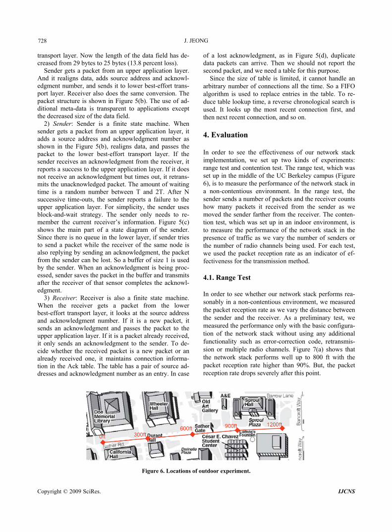
Since the size of table is limited, it cannot handle an arbitrary number of connections all the time. So a FIFO algorithm is used to replace entries in the table. To re-duce table lookup time, a reverse chronological search is used. It looks up the most recent connection first, and then next recent connection, and so on. 4. Evaluation In order to see the effectiveness of our network stack implementation, we set up two kinds of experiments: range test and contention test. The range test, which was set up in the middle of the UC Berkeley campus (Figure 6), is to measure the performance of the network stack in a non-contentious environment. In the range test, the sender sends a number of packets and the receiver counts how many packets it received from the sender as we moved the sender farther from the receiver. The conten-tion test, w
s- Receiver also does the same convers
e lower best-effort transport
knowledgment from the recei
part of a state diagram measure the performance of the network stack in the presence of traffic as we vary the number of senders or the number of radio channels being used. For each test, we used the packet reception rate as an indicator of ef-fectiveness for the transmission method. 4.1. Range Test In order to see whether our network stack performs rea-sonably in a non-contentious environment, we measured the packet reception rate as we vary the distance between the sender and the receiver. As a preliminary test, we measured the performance only with the basic configura-tio
is no queue in the lower layer, if sacket while the receiver of the sa
aom the sender can be lost. So a buffer of size 1 is used
by the sender. When an acknowledgment is being proc-essed, sender saves the packet in the buffer and transmits after the receiver of that sensor completes the acknowl-edgment.
3) Receiver: Receiver is also a finite state machine. When the receiver gets a packet from the lower best-effort transport layer, it looks at the source address and acknowledgment number. If it is a new packet, it sends an acknowledgment and passes the packet to the upper application layer. If it is a packet already received, it
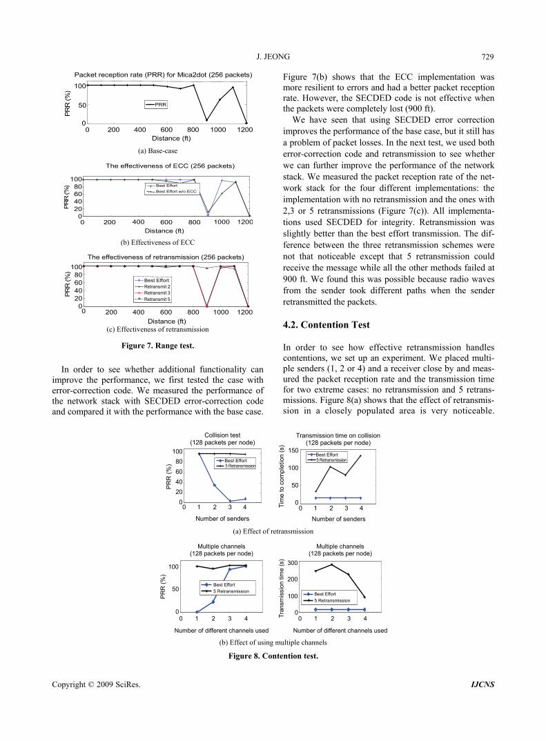
n of the network stack without using any additional functionality such as error-correction code, retransmis-sion or multiple radio channels. Figure 7(a) shows that the network stack performs well up to 800 ft with the packet reception rate higher than 90%. But, the packet reception rate drops severely after this p
only sends an acknowledgment to the sender. To de-cide whether the received packet is a new packet or an already received one, it maintains connection informa-tion in the Ack table. The table has a pair of source ad-dresses and acknowledgment number as an entry. In case
utdoor experiment. Figure 6. Locations of o
J. JEONG 729
0 200 400 600 800 1000 1200Distance (ft)
PRR
0
50
100
PR
R (%
)Packet reception rate (PRR) for Mica2dot (256 packets)
(a) Base-case
Distance (ft)
The effectiveness of ECC (256 packets)
200 400 600 800 1000 1200
100 80 60 40 20 0
PR
R (%
)
Best Effort
Best Effort w/o ECC
0
(b) Effectiveness of ECC
The effectiveness of retransmission (256 packets)
200
100806040200
Distance (ft)
PR
R (%
)
Best EffortRetransmit 2 Retransmit 3 Retransmit 5
400 600 800 1000 12000
4.2. Contention T(c) Effectiveness of retransmission
Figure 7. Range test.
In order to see whether additional functionality can
improve the performance, we first tested the case with error-correction code. We measured the performance of the network stack with SECDED error-correction c e and compared it with th ce with the base case.
tations: the implementation with no retransmission and the ones with 2,3 or 5 retransmissions (Figure 7(c)). All implementa-tions used SECDED for integrity. Retransmission was slightly better than the best effort transmission. The dif-ference between the three retransmission schemes were not that noticeable except that 5 retransmission could receive the message while all the other methods failed at 900 ft. We found this was possible because radio waves from the sender took different paths when the sender retransmitted the packets.
est
and 5 retrans-m
ode performan
Figure 7(b) shows that the ECC implementation was more resilient to errors and had a better packet reception rate. However, the SECDED code is not effective when the packets were completely lost (900 ft).
We have seen that using SECDED error correction improves the performance of the base case, but it still has a problem of packet losses. In the next test, we used both error-correction code and retransmission to see whether we can further improve the performance of the network stack. We measured the packet reception rate of the net-work stack for the four different implemen
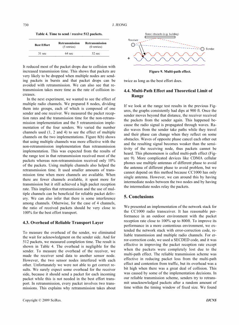
In order to see how effective retransmission handles contentions, we set up an experiment. We placed multi-ple senders (1, 2 or 4) and a receiver close by and meas-ured the packet reception rate and the transmission time for two extreme cases: no retransmission
issions. Figure 8(a) shows that the effect of retransmis-sion in a closely populated area is very noticeable.
Number of senders
PR
R (
%)
100
80
60
40
20
Collision test (128 packets per node) )
0
Best Effort5 Retransmission
0 1 2 3 4 Tim
e to
com
plet
ion
(s 150
100
50
0
Transmission time on collision(128 packets per node)
Best Effort5 Retransmission
0 1 2 3 4
Number of senders ansmission (a) Effect of retr
Multiple channels (128 packets per node)
%
Number of different channels used
PR
R (
)
0
100
Best Effort
5 Retransmission
1 2 3 4
50
0
Multiple channels (128 packets per node)
Tra
nsm
issi
on t
ime
(s)
Best Effort
0 1 2 3 4
100
g m
onte
5 Retransmission
0
Number of different channels used ultiple channels
ntion test.
300
200
(b) Effect of usin
Figure 8. C
Copyright © 2009 SciRes. IJCNS
J. JEONG 730
Best Effort Retransmission
(5 retries) Retransmission
(0 retries)
Table 4. Time to send / receive 512 packets.
31 sec 64 sec 32 sec
It reduced most of the packet drops due to collision with increased transmission time. This shows that packets are very likely to be dropped when multiple nodes are send-ing packets in bursts and that packet drops can be avoided with retransmission. We can also see that re-transmission takes more time as the rate of colcreases.
In the next experiment, we wanted to see the effect of multiple radio channels. We prepared 8 nodes, dividing them into groups, each of which is composed of one sender and one receiver. We measured the packet recep-tion rates and the transmission time for the non-retrans-mission implementation and the 5 retransmission imple-mentation of the four senders. We varied the number channels used (1, 2 and 4) to see the effect of multiple channels on the two implementations. Figurethat using multiple channels was more effecon-retransmission implementation than retra
plem ults of the range test in that retransmission received most of the packets non r 10% of the sing m annels ed the retransmission time. It u aller amo trans-mission time when more channels are available. When
ere are fewer channels available, it spent more for
e best effort transport.
lision in-
8(b) shows tive with the
nim
nsmission entation. This was expected from the res
whereas packets. U
-retransmission eceived only ultiple ch also helpsed sm unts of
thtransmission but it still achieved a high packet reception rate. This implies that retransmission and the use of mul-tiple channels can be beneficial for reliable packet deliv-ery. We can also infer that there is some interference among channels. Otherwise, for the case of 4 channels, the ratio of received packets should be very close to 100% for th
4.3. Overhead of Reliable Transport Layer To measure the overhead of the sender, we eliminated the wait for acknowledgment on the sender side. And for 512 packets, we measured completion time. The result is shown in Table 4. The overhead is negligible for the sender. To measure the overhead of the receiver, we made the receiver send data to another sensor node. However, the two sensor nodes interfered with each other. Unfortunately we were not able to get correct re-sults. We surely expect some overhead for the receiver side, because it should send a packet for each incoming packet while this is not needed in the best effort trans-port. In retransmission, every packet involves two trans-missions. This explains why retransmission takes about
Figure 9. Multi-path effect. twice as long as the best effort does.
ti-Path Effect and Theoretical Limit of Range
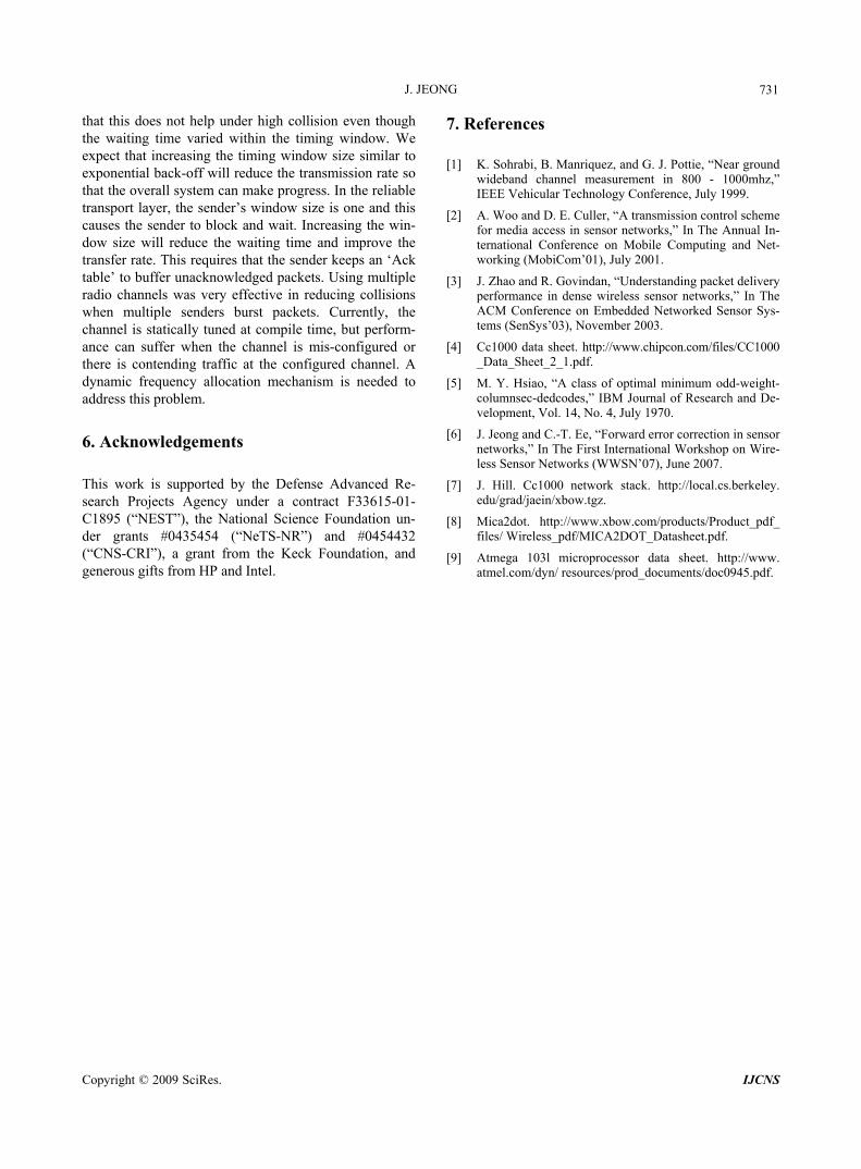
If we look at the range test results in the previous Fig-ures, the graphs consistently had dips at 900 ft. Once the sender moves beyond that distance, the receiver received the packets from the sender again. This happened be-cause the radio signal is propagated through waves. Ra-dio waves from the sender take paths while they travel and their phase can change when they reflect on some
ves of opposite phase cancel each other out ulting signal becomes weaker than the sensi-
was caused by some of the implementation decisions. In our reliable transmission scheme, senders try to retrans-mit unacknowledged packets after a random amount of time within the timing window of fixed size. We found
4.4. Mul
obstacles. Waand the restivity of the receiving node, thus packets cannot be heard. This phenomenon is called multi-path effect (Fig-ure 9). More complicated devices like CDMA cellular phones use multiple antennas of different phase to avoid the antenna of different phase to avoid problem, but we cannot depend on this method because CC1000 has only single antenna. However, we can around this by having intermediate nodes between the two nodes and by having the intermediate nodes relay the packets. 5. Conclusions We presented an implementation of the network stack for the CC1000 radio transceiver. It has reasonable per-formance in an outdoor environment with the packet reception rate close to 100% up to 800ft. To improve its performance in a more contentious environment, we ex-tended the network stack with error-correction code, re-liable transmission and multiple radio channels. For er-ror-correction code, we used a SECDED code, and it was effective in improving the packet reception rate except when the packets were completely lost due to the multi-path effect. The reliable transmission scheme was effective in reducing packet loss from the multi-path effect and contention from traffic, but its overhead was a bit high when there was a great deal of collision. This
Copyright © 2009 SciRes. IJCNS
J. JEONG
731
that this does not help under high collision even though the waiting time varied within the timing window. We expect that increasing the timing window size similar to exponential back-off will reduce the transmission rate so that the overall system can make progress. In the reliable transport layer, the sender’s window size is one and this causes the sender to block and wait. Increasing the window size will reduce t improve the
rate. T keeps an ‘Ack s. Using multiple
reducing collisions
-nce er when the channel is mis-configured or ere is contending traffic at the configured channel. A
s,” IBM Journal of Research and De-velopment, Vol. 14, No. 4, July 1970.
rward error correction in sensor ternational Workshop on Wire-
less Sensor Networks (WWSN’07), June 2007.
945.pdf.
-he waiting time and
his requires that the sender transfer table’ to buffer unacknowledged packetadio channels was very effective inr
when multiple senders burst packets. Currently, the channel is statically tuned at compile time, but perform
can suffathdynamic frequency allocation mechanism is needed to address this problem.
6. Acknowledgements This work is supported by the Defense Advanced Re-search Projects Agency under a contract F33615-01- C1895 (“NEST”), the National Science Foundation un-der grants #0435454 (“NeTS-NR”) and #0454432 (“CNS-CRI”), a grant from the Keck Foundation, and generous gifts from HP and Intel.
7. References
[1] K. Sohrabi, B. Manriquez, and G. J. Pottie, “Near ground wideband channel measurement in 800 - 1000mhz,” IEEE Vehicular Technology Conference, July 1999.
[2] A. Woo and D. E. Culler, “A transmission control scheme for media access in sensor networks,” In The Annual In-ternational Conference on Mobile Computing and Net-working (MobiCom’01), July 2001.
[3] J. Zhao and R. Govindan, “Understanding packet delivery performance in dense wireless sensor networks,” In The ACM Conference on Embedded Networked Sensor Sys-tems (SenSys’03), November 2003.
[4] Cc1000 data sheet. http://www.chipcon.com/files/CC1000 _Data_Sheet_2_1.pdf.
[5] M. Y. Hsiao, “A class of optimal minimum odd-weight- columnsec-dedcode
[6] J. Jeong and C.-T. Ee, “Fonetworks,” In The First In
[7] J. Hill. Cc1000 network stack. http://local.cs.berkeley. edu/grad/jaein/xbow.tgz.
[8] Mica2dot. http://www.xbow.com/products/Product_pdf_ files/ Wireless_pdf/MICA2DOT_Datasheet.pdf.
[9] Atmega 103l microprocessor data sheet. http://www. atmel.com/dyn/ resources/prod_documents/doc0
Copyright © 2009 SciRes. IJCNS


![Neural Network Approach to Response of Buildings Due to ...file.scirp.org/pdf/IJG20120300002_12603224.pdf · Neural Network Approach to Response of Buildings ... funac [3-6] studied](https://img.pdfslide.net/doc/110x75/5ac5e0837f8b9a57528de6b1/neural-network-approach-to-response-of-buildings-due-to-filescirporgpdfijg20120300002.jpg)