Embed Size (px)
Citation preview

Abstract—This article deals with the influence of barrel wear and
barrel thermal deformation of tank cannon on the ramming process.
Barrel wear was used as input data from measuring on 125 mm
smooth tank cannon barrels. Barrel thermal deformation and the
ramming process of APFSDS (Armor-Piercing Fin-Stabilized
Discarding Sabot) projectiles were calculated using ANSYS
Workbench software utilizing the Finite Element Method (FEM). The
ramming process calculation was done for two case scenarios: the
first case was for a new barrel deformed by barrel thermal effects
from firing; the second case was for a worn barrel influenced by the
same thermal effects. The reaction force as the most important
standardized factor used to evaluate the effect and safety of the
ramming process is verified by experiment performed on the above
mentioned 125 mm weapon system. The calculated results are
reasonably compatible with the experimental results. The research
results also provide a background for the state-of-the-art knowledge
to upgrade the Czech Defense Standards (COS) for the ramming
device of artillery weapons and tanks.
Keywords— Barrel thermal deformation, barrel wear, forcing
cone, ramming process, tank cannon loading
I. INTRODUCTION
T IS known that the combat efficiency of artillery, especially
self-propelled howitzers and tanks depends on many tactical
and technical factors, see [15], [16], [30], and [35]. One of the
most important technical factors is the rapidity of fire and the
safety of projectile ramming during unstable motion of
fighting vehicles on the battlefield. A very important factor is
the safety of projectile ramming while a fighting vehicle in the
battlefield is moving fast and over bad terrain or bad road
conditions when a heavy projectile must not fall down from
the cartridge chamber, see [1], [4], and [7].
Manuscript received January 4, 2013. This work was supported by the
research project: POV DELO No. OVUOFVT200901. J. Balla is with the University of Defense, Kounicova 65, 662 10 Brno,
Czech Republic (corresponding author to provide phone: 00 420 973 44 5013;
e-mail: [email protected]) and Alexander Dubcek University of Trenčín, Studentska 2, 911 50 Trencin, Slovakia; email: [email protected].
V. Y. Duong is with the University of Defense, Kounicova 65, 662 10
Brno, Czech Republic; e-mail: [email protected]). S. Prochazka is with the University of Defence, Kounicova 65, 662 10
Brno, Czech Republic (corresponding author to provide phone: 00 420 973 44
5268; fax: 00 420 973 44 5011; e-mail: stanislav.prochazka@ unob.cz).
Therefore, both the rapidity and safety of ramming depend on
the quality of the ramming device which is a very important
part of the loading device. Firstly, the ramming device secures
the projectile in the barrel while the projectile is engraved into
the barrel forcing cone, thus preventing the risk of projectile
fallback, see [2], [3], [26] and [27]. Secondly, the ramming
process creates a deformation field between the driving band
and the forcing cone to seal the air-gap between the powder
chamber and the guidance section of the barrel, ensuring the
powder gas does not leak through this air-gap when firing, see
[6], [9], and [36]. Thirdly, the accurate position of the
projectile in the chamber after ramming gives a steady
movement to the projectile in the barrel and decreases
vibration of the projectile which, together with all the above
mentioned factors, increases firing accuracy, see [21], [25],
and [27]. Generally it is mentioned in [26] with respect to the
ramming devices and rammed projectiles. The interface
configuration between the chamber, the forcing cone and
ammunition shall ensure that no projectile falls back out of its
seating, at any angle of elevation, between the action of
loading and exiting the barrel by firing. To reduce the risk of
fall back to a minimum, the following shall be taken into
account during design and development. Besides the
coincidence of the rammer axis with the bore axis, the rammer
head must remain in firm with the base of projectile as it
drives the projectile into its seating. When hand ramming is in
operation (as back up of a motor drive), with or without the
use of a stave, contact between hands and the equipment
should be prevented when ramming at any elevation angle and
traverse.
As, potentially, fall back can cause premature explosion in
the bore, trials are required to establish the degree of risk
involved both power ramming, in follow-through and flick
modes, and hand ramming. In these trials, the force required to
eject a projectile which has been correctly rammed is
measured by a load cell or other device.
According to [26] the ejection force is assumed to be same
as the retention force holding the projectile in the rammed,
seated, position. Flick rammed projectile subjected to too high
velocity of ram may sustain filling, cargo, sub-components or
fuse damage. Trials to establish the margin of safety (upper
threshold) are required. Other trials are necessary to ensure
Evaluation of projectile ramming process in new
and worn smooth barrels of guns
Jiri Balla, Stanislav Prochazka, Van Yen Duong
I
INTERNATIONAL JOURNAL OF MECHANICS
Issue 2, Volume 7, 2013 136
that rammed, correctly seated projectiles do not become
dislodged during laying drills, movement (in case of tanks
when loaded in readiness for engagement) or as a result of any
operational vibration.
The test procedure is described very shortly. A series of not
less than 20 projectiles is to be rammed and ejected with the
ejection force being measured for each projectile in the series.
After ejection, each round should be examined, and if found to
be satisfactory, rammed again and fired. Ramming is to be
carried out at the maximum permissible loading elevation and
at any lower elevations considered critical.
The several of data are recorded. There are several of them:
the velocity of the ramming, the depth of ram and finally the
ejection force.
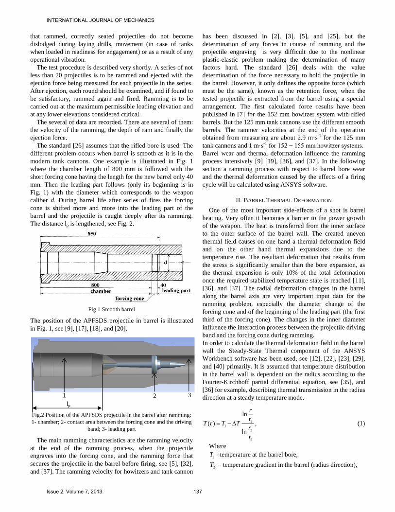
The standard [26] assumes that the rifled bore is used. The
different problem occurs when barrel is smooth as it is in the
modern tank cannons. One example is illustrated in Fig. 1
where the chamber length of 800 mm is followed with the
short forcing cone having the length for the new barrel only 40
mm. Then the leading part follows (only its beginning is in
Fig. 1) with the diameter which corresponds to the weapon
caliber d. During barrel life after series of fires the forcing
cone is shifted more and more into the leading part of the
barrel and the projectile is caught deeply after its ramming.
The distance lp is lengthened, see Fig. 2.
Fig.1 Smooth barrel
The position of the APFSDS projectile in barrel is illustrated
in Fig. 1, see [9], [17], [18], and [20].
Fig.2 Position of the APFSDS projectile in the barrel after ramming:
1- chamber; 2- contact area between the forcing cone and the driving
band; 3- leading part
The main ramming characteristics are the ramming velocity
at the end of the ramming process, when the projectile
engraves into the forcing cone, and the ramming force that
secures the projectile in the barrel before firing, see [5], [32],
and [37]. The ramming velocity for howitzers and tank cannon
has been discussed in [2], [3], [5], and [25], but the
determination of any forces in course of ramming and the
projectile engraving is very difficult due to the nonlinear
plastic-elastic problem making the determination of many
factors hard. The standard [26] deals with the value
determination of the force necessary to hold the projectile in
the barrel. However, it only defines the opposite force (which
must be the same), known as the retention force, when the
tested projectile is extracted from the barrel using a special
arrangement. The first calculated force results have been
published in [7] for the 152 mm howitzer system with rifled
barrels. But the 125 mm tank cannons use the different smooth
barrels. The rammer velocities at the end of the operation
obtained from measuring are about 2.9 m·s-1
for the 125 mm
tank cannons and 1 m·s-1
for 152 − 155 mm howitzer systems.
Barrel wear and thermal deformation influence the ramming
process intensively [9] [19], [36], and [37]. In the following
section a ramming process with respect to barrel bore wear
and the thermal deformation caused by the effects of a firing
cycle will be calculated using ANSYS software.
II. BARREL THERMAL DEFORMATION
One of the most important side-effects of a shot is barrel
heating. Very often it becomes a barrier to the power growth
of the weapon. The heat is transferred from the inner surface
to the outer surface of the barrel wall. The created uneven
thermal field causes on one hand a thermal deformation field
and on the other hand thermal expansions due to the
temperature rise. The resultant deformation that results from
the stress is significantly smaller than the bore expansion, as
the thermal expansion is only 10% of the total deformation
once the required stabilized temperature state is reached [11],
[36], and [37]. The radial deformation changes in the barrel
along the barrel axis are very important input data for the
ramming problem, especially the diameter change of the
forcing cone and of the beginning of the leading part (the first
third of the forcing cone). The changes in the inner diameter
influence the interaction process between the projectile driving
band and the forcing cone during ramming.
In order to calculate the thermal deformation field in the barrel
wall the Steady-State Thermal component of the ANSYS
Workbench software has been used, see [12], [22], [23], [29],
and [40] primarily. It is assumed that temperature distribution
in the barrel wall is dependent on the radius according to the
Fourier-Kirchhoff partial differential equation, see [35], and
[36] for example, describing thermal transmission in the radius
direction at a steady temperature mode.
1
1
2
1
ln
( )
ln
r
rT r T T
r
r
, (1)
Where
1T –temperature at the barrel bore,
2T – temperature gradient in the barrel (radius direction),
1 2 3
lp
INTERNATIONAL JOURNAL OF MECHANICS
Issue 2, Volume 7, 2013 137

1 2,r r – barrel internal and external radius.
The results of the calculations are the heat fields in the
barrel wall. These heat fields are used as input data for using
the Static Structural component of the ANSYS Workbench
software to calculate the thermal deformation fields.
The FEM model for the tank cannon barrel during all
loading projectile process was worked out using [8], [10],
[13], [14], [24], [28], [31], [33], [34], [39], and [40] and is
shown in Fig. 3. The circle indicated as a represents the
forcing cone area.
Fig.3 Model of a 125 mm tank cannon barrel
The results of calculations have been tested by way of
comparison with the analytical solution of the heavy-walled
barrel. The boundary conditions at the end of the calculated
area were set from the conditions of non-deformation area in
the axial direction outside of the calculated area.
The interactions between the projectile driving band and the
forcing cone occur in the A-A and B-B cross-sections.
Temperature distribution from the inner surface to the outer
surface is shown in Fig. 4. The temperature on the inner
surface is, from experience, set at 350°C taking into account
the requirement not to exceed the maximum recommended
temperature on this surface. The temperature decreases in the
radial direction from the inner to the outer surface. The
temperature gradient, at the steady temperature state, reaches
150° – 200°C for heavy gun barrels, see [19], and [36]. In this
case the temperature on the outer surface was calculated as
200°C. The calculated temperature fields – see Fig. 4 – create
the input data for the barrel deformation problem.
The calculation results of barrel thermal deformation are
shown in Fig. 5.
After each shot, the shape of the barrel forcing cone is
changed due to the barrel thermal deformation. This change
forms a new shape in the barrel forcing cone. The calculation
results of the radial thermal deformation of the inner surface
along the barrel length are approximately 0.3 mm (see Fig. 6).
Fig.4 Temperature field in barrel wall
The maximum values are around the forcing cone of the
barrel. Those are the danger areas for securing the projectile in
the barrel post-ramming, see [7], [17], and [36].
Fig.5 Radial thermal deformation field (m) of barrel wall
Fig.6 Barrel radial thermal deformation of the inner surface along
the barrel length
III. BARREL WEAR
The ramming process is influenced not only by barrel thermal
deformation, but also by barrel wear that influences projectile
ramming more intensively than barrel thermal deformations.
This can be explained by the main reason that rapidity of fire
of self-propelled howitzers as well as tank cannons is quite
low (6 to 8 rounds/min). The time from previous firing cycle
to the next firing cycle is quite long with respect to the
duration of barrel temperature drop. The barrel temperature
drops and the elastic thermal deformations of the barrel
disappear or reduce to zero before the next firing cycle is
performed. However, in order to satisfy the safety
requirements of any weapon system operation, the ramming
process with simultaneous influences of barrel thermal
deformations and barrel wear will be researched.
Measurement results for the 125 mm worn cannon barrels
performed by the Department of Weapons and Ammunition
are shown in Fig. 7, Fig. 8, and Fig. 9, [17], [18], [19], and
[20]. The measured value is the inner barrel bore diameter.
The inner diameter of the new cannon barrel bore is 125+0.15
mm. The limited diameter of barrel behind the forcing cone
(850 mm from bottom) is 128.3 mm. The projectile
manufacturing tolerance of diameter is 129-0.4
mm.
Then it can be 128.6 mm. It is reason why the occurrence of
the initial barrel chamber volume increasing when new
projectile is rammed into the worn barrel – projectile does not
stop as in the new barrel, but deeply. In all these mentioned
figures the barrel length starts from 800 mm. It is the
beginning of the forcing cone followed by the leading part of
the barrel bore, see Fig. 1 as well. According to [17] it is
known that APFSDS projectiles cause different character of
INTERNATIONAL JOURNAL OF MECHANICS
Issue 2, Volume 7, 2013 138

wear unlike HEAT (high explosive anti-tank) and HE (high
explosive) projectiles.
Usually the barrel wear firing APFSDS projectile is more than
eight times greater than barrel wear using HEAT and HE
projectiles.
Fig.7 Wear of cannon barrel bore firing mainly APFSDS projectiles
with ferrous sabot
Fig.8 Wear of cannon barrel bore firing HE projectiles
The growth of the wear behind the forcing cone in the Fig.7
has been discussed in [17], [19], and [20].
The differences of driving band shape between APFSDS and
HE (high explosive) projectiles, quantity of fired rounds etc.
cause that the barrels wear to be in the different range of
values. The barrel firing mainly APFSDS projectiles with
ferrous sabots is worn out more intensively than the barrel
firing new APFSDS projectiles using the nonferrous sabots.
Evidently, barrel wear occurs more intensively at the region of
the forcing cone and at the beginning of the leading part of the
barrel bore (the first third of the forcing cone). Wear of the
forcing cone and the leading part can be generally specified by
increasing of the diameter at a point between the forcing cone
and the leading part, see Fig. 1.
Fig.9 Wear of cannon barrel bore firing mainly APFSDS projectiles
with nonferrous sabot
IV. INFLUENCES OF BARREL THERMAL DEFORMATION AND
BARREL WEAR ON PROJECTILE ENGRAVING
As it is mentioned in last sections the barrel wear influences
the engraving of the projectile at the end of the ramming
process as it is explained in Fig. 10 where are three cases –
new barrel, worn barrel, and worn and heated barrel. The case
with thermal deformation from heating is exaggerated due to
clear explanation of the research object. The main results are
that the projectile is rammed deeply into the barrel and it can
cause serious problems in service as it is represented by the lp
length in Fig. 10.
Fig.10 Explanation of projectile position in different barrels
The calculation and simulation have been carried out for two
cases with helping of The Transient Structural component of
the ANSYS Workbench software.
The position of the projectile before and after ramming, where
it is engraved is shown in Fig. 11 for the new barrel. The place
of the driving band is marked by the red circle.
0 1000 2000 3000 4000 5000 6000125
126
127
128
129
130
131
barrel bore length (mm)
barrel
bore in
ner
dia
mete
r (
mm
)
APFSDS projectile
0 1000 2000 3000 4000 5000 6000125
126
127
128
129
130
131
barrel bore length (mm)
barrel
bore in
ner
dia
mete
r (
mm
) HE projectile
0 1000 2000 3000 4000 5000 6000124
125
126
127
128
129
130
131
barrel bore length (mm)
barrel
bore in
ner
dia
mete
r (
mm
)
APFSDS projectile with
nonferrous sabot
INTERNATIONAL JOURNAL OF MECHANICS
Issue 2, Volume 7, 2013 139

Fig.11 Projectile position before and after ramming – new barrel
The FEM model of the ramming problem is shown in Fig. 12
after magnification. The boundary conditions are set for the
problem, including fixed position of the barrel at the barrel
bottom and the initial ramming velocity of the projectile. The
projectile velocity the rammer velocity at its end position,
where the ramming device stops but the projectile moves
continuously in the direction of the barrel axis with an initial
velocity of 2.9 m·s-1
, see Fig. 14, and Fig. 20.
The first case describes the geometry of a new barrel with the
thermal deformations determined in ANSYS Workbench
using FEM. The ramming process of the APFSDS projectile
was simulated and calculated on this model base.
Fig.12 FEM model of driving band engraving
The equivalent stress (Von-Misses) with the thermal
deformation effect in the new barrel is 212 MPa. The
calculated reaction engraving force achieved at the process
beginning is more than 20 kN, see Fig. 13, and the projectile
velocity drops after 2 ms approximately, see Fig. 14. The
measurement of this force is very difficult. The validity of the
FEM model has been performed indirectly using the unique
measuring device designed at Weapons and ammunition
department of University of Defence in Brno during research
works on the project Delo (this word means Cannon in
English) as other works [17], [18], [19], [20], and [37].
Fig.13 Reaction force in a new barrel
Fig.14 Projectile velocity in a new barrel
The measuring equipment is depicted in Fig. 15.
Fig.15 Force measurement device
The device is able to determine the extraction force from the
barrel at 125 mm tank cannon and 152 mm howitzer. This
force equals to the retention force according to the standard
[26]. The two fixation centering sleeves are used for it.
The fixation centering sleeve having the HBM displacement
gauge inserts into the barrel and fixes to the barrel chamber
and it have to touch-down on the barrel bottom. After sleeve
centering this is fixed by means of the eight threads.
The initial position of the displacement gauge is set and
ensured with the pull rod and the screw. The pull rod is
connected with the extracted projectile via the tie tube having
the bayonet joint. The hook-type towing attachment is put
INTERNATIONAL JOURNAL OF MECHANICS
Issue 2, Volume 7, 2013 140
together with the fixation centering sleeve and the pull rod is
united with the HBM force gauge through the coupling pin.
By means of the hand wheel is the projectile pulled out of the
barrel. The second prototype will use the DC electric motor
due to the extraction force should be independent on the crew.
Special measuring arrangement enables the record both the
extraction force and the projectile displacement (and
additionally time as well). The evaluation software is in
disposition with additional export data into ASCII format
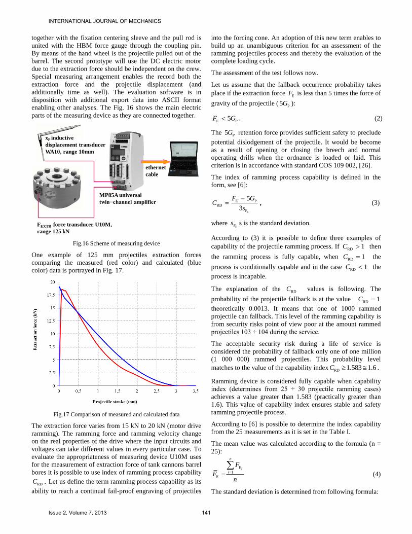
enabling other analyses. The Fig. 16 shows the main electric
parts of the measuring device as they are connected together.
Fig.16 Scheme of measuring device
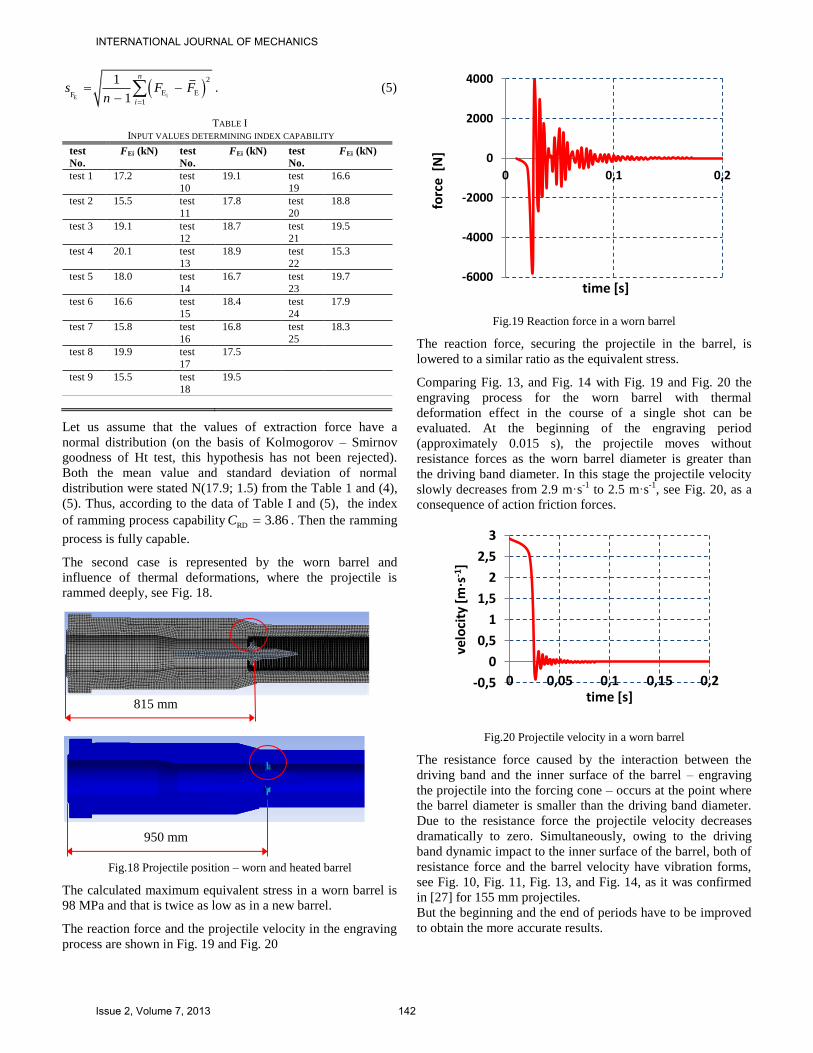
One example of 125 mm projectiles extraction forces
comparing the measured (red color) and calculated (blue
color) data is portrayed in Fig. 17.
Fig.17 Comparison of measured and calculated data
The extraction force varies from 15 kN to 20 kN (motor drive
ramming). The ramming force and ramming velocity change
on the real properties of the drive where the input circuits and
voltages can take different values in every particular case. To
evaluate the appropriateness of measuring device U10M uses
for the measurement of extraction force of tank cannons barrel
bores it is possible to use index of ramming process capability
RDC . Let us define the term ramming process capability as its
ability to reach a continual fail-proof engraving of projectiles
into the forcing cone. An adoption of this new term enables to
build up an unambiguous criterion for an assessment of the
ramming projectiles process and thereby the evaluation of the
complete loading cycle.
The assessment of the test follows now.
Let us assume that the fallback occurrence probability takes
place if the extraction force EF is less than 5 times the force of
gravity of the projectile (P5G ):
E P5F G . (2)
The P5G retention force provides sufficient safety to preclude
potential dislodgement of the projectile. It would be become
as a result of opening or closing the breech and normal
operating drills when the ordnance is loaded or laid. This
criterion is in accordance with standard COS 109 002, [26].
The index of ramming process capability is defined in the
form, see [6]:
E
E P
RD
F
5
3
F GC
s
, (3)
where EFs s is the standard deviation.
According to (3) it is possible to define three examples of
capability of the projectile ramming process. If RD 1C then
the ramming process is fully capable, when RD 1C the
process is conditionally capable and in the case RD 1C the
process is incapable.
The explanation of the RDC values is following. The
probability of the projectile fallback is at the value RD 1C
theoretically 0.0013. It means that one of 1000 rammed
projectile can fallback. This level of the ramming capability is
from security risks point of view poor at the amount rammed
projectiles 103 ÷ 104 during the service.
The acceptable security risk during a life of service is
considered the probability of fallback only one of one million
(1 000 000) rammed projectiles. This probability level
matches to the value of the capability index RD 1.583 1.6C .
Ramming device is considered fully capable when capability
index (determines from 25 ÷ 30 projectile ramming cases)
achieves a value greater than 1.583 (practically greater than
1.6). This value of capability index ensures stable and safety
ramming projectile process.
According to [6] is possible to determine the index capability
from the 25 measurements as it is set in the Table I.
The mean value was calculated according to the formula (n =
25):
iE
1
E
n
i
F
Fn
(4)
The standard deviation is determined from following formula:
xP inductive
displacement transducer
WA10, range 10mm
FEXTR force transducer U10M,
range 125 kN
MP85A universal
twin−channel amplifier
ethernet
cable
INTERNATIONAL JOURNAL OF MECHANICS
Issue 2, Volume 7, 2013 141
iE
2
E EF1
1
1
n
i
s F Fn
. (5)
TABLE I
INPUT VALUES DETERMINING INDEX CAPABILITY
test
No.
FEi (kN) test
No.
FEi (kN) test
No.
FEi (kN)
test 1 17.2 test
10
19.1 test
19
16.6
test 2 15.5 test
11
17.8 test
20
18.8
test 3 19.1 test
12
18.7 test
21
19.5
test 4 20.1 test
13
18.9 test
22
15.3
test 5 18.0 test
14
16.7 test
23
19.7
test 6 16.6 test
15
18.4 test
24
17.9
test 7 15.8 test
16
16.8 test
25
18.3
test 8 19.9 test
17
17.5
test 9 15.5 test
18
19.5
Let us assume that the values of extraction force have a
normal distribution (on the basis of Kolmogorov – Smirnov
goodness of Ht test, this hypothesis has not been rejected).
Both the mean value and standard deviation of normal
distribution were stated N(17.9; 1.5) from the Table 1 and (4),
(5). Thus, according to the data of Table I and (5), the index
of ramming process capability RD 3.86C . Then the ramming
process is fully capable.
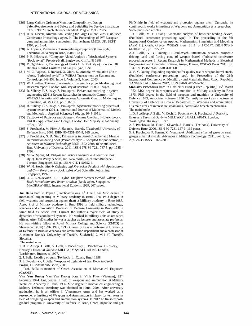
The second case is represented by the worn barrel and
influence of thermal deformations, where the projectile is
rammed deeply, see Fig. 18.
Fig.18 Projectile position – worn and heated barrel
The calculated maximum equivalent stress in a worn barrel is
98 MPa and that is twice as low as in a new barrel.
The reaction force and the projectile velocity in the engraving
process are shown in Fig. 19 and Fig. 20
Fig.19 Reaction force in a worn barrel
The reaction force, securing the projectile in the barrel, is
lowered to a similar ratio as the equivalent stress.
Comparing Fig. 13, and Fig. 14 with Fig. 19 and Fig. 20 the
engraving process for the worn barrel with thermal
deformation effect in the course of a single shot can be
evaluated. At the beginning of the engraving period
(approximately 0.015 s), the projectile moves without
resistance forces as the worn barrel diameter is greater than
the driving band diameter. In this stage the projectile velocity
slowly decreases from 2.9 m·s-1
to 2.5 m·s-1
, see Fig. 20, as a
consequence of action friction forces.
Fig.20 Projectile velocity in a worn barrel
The resistance force caused by the interaction between the
driving band and the inner surface of the barrel – engraving
the projectile into the forcing cone – occurs at the point where
the barrel diameter is smaller than the driving band diameter.
Due to the resistance force the projectile velocity decreases
dramatically to zero. Simultaneously, owing to the driving
band dynamic impact to the inner surface of the barrel, both of
resistance force and the barrel velocity have vibration forms,
see Fig. 10, Fig. 11, Fig. 13, and Fig. 14, as it was confirmed
in [27] for 155 mm projectiles.
But the beginning and the end of periods have to be improved
to obtain the more accurate results.
-6000
-4000
-2000
0
2000
4000
0 0,1 0,2
forc
e [
N]
time [s]
-0,5
0
0,5
1
1,5
2
2,5
3
0 0,05 0,1 0,15 0,2
velo
city
[m·s
-1]
time [s] 815 mm
950 mm
INTERNATIONAL JOURNAL OF MECHANICS
Issue 2, Volume 7, 2013 142

V. CONCLUSION
For a new barrel, where the barrel dimensions are given in
the technical documentation, the distance between the initial
projectile position where the impact starts and stops, was 3 – 5
mm. The distance in the worn barrel, as represented in Fig. 18,
was much greater than for the new barrel reaching up to 150
mm, see Fig. 12. The prolongation of the ramming
displacement leads to a rise in the volume of the barrel
chamber causing a change in the development of barrel gas
pressure. The place of the maximum value of the gas pressure
in the barrel shifts to the place where the barrel thickness is
smaller. This phenomenon can cause the risk of barrel
chamber elongation. A permanent elongation can occur when
the barrel wear is greater than the value specified in the
technical documentation of the Czech Defence Standards, see
[26] for requirements of the loading process. Then barrel
explosion can occur. This problem is very important for
APFSDS projectiles whose velocities go beyond 1500 m·s-1
.
The increase in resistance forces, caused by the driving
band engraving, happens in the region where the worn barrel
diameter is smaller than the driving band diameter. In such a
case the projectile is rammed deeper than in an unworn barrel
and projectile velocity at the beginning of the engraving is
lower as a consequence of the projectile movement by inertia.
In a new barrel the rammer is designed to stop its movement at
the start of the projectile driving band in the forcing cone. If
the rammer stroke was greater rammer deformation could
occur. For this reason the rammer velocity was increased up to
3 m·s-1
. This measure ensured that the projectile would also be
held in a worn barrel at any elevation angle when loading on
the move where significant inertia forces strongly influence
the loading system.
The impact and the interaction between the driving band
and the inner barrel surface are non-linear dynamic processes
and the velocities and the reaction forces have their typical
oscillating movement known as the ping-pong effect, see [27].
In the future, the measuring of reaction forces using the new
HBM measuring device with electric drive instead of hand one
and specification of the input data for FEM shall be
conducted.
REFERENCES
[1] J. Balla, “Dynamics of Mounted Automatic Cannon on Track Vehicle
(Periodical style)”, In International Journal of Mathematical Models
and Methods in Applied Sciences). NAUN press, December 2011, pp.
423-432. ISSN 1998-0140. [2] J. Balla, V. Y. Duong., Jankovych. R., Evaluation of 152 mm SPH
M77 ramming device. (Published Conference Proceedings style),” In
Proceedings from International Conference on Military Technologies. Brno University of Defence, 2011, ISBN 978-80-7231-787-5, pp. 1625-
1634.
[3] J. Balla, V. Y. Duong, R. Jankovych, Technical Inspection of 125 mm tank cannon ramming device. (Published Conference Proceedings
style),” In The Proceedings from International Conference on Military
Technologies. Brno: University of Defence, 2011, ISBN 978-80-7231-787-5, pp. 1635-1644.
[4] J. Balla, V. Y. Duong, “Analysis of feeding device with two degrees of
freedom (Periodical style)”, In International Journal of Mechanics. NAUN press, 2011, pp. 361-370. ISSN 1998-4448.
[5] J. Balla, “Twin motor drives in weapon systems (Periodical style)”,
WSEAS Transactions on Systems and Control, vol. 5, Issue 9, pp. 755-
765, Sept. 2010, ISSN: 1991-8763.
[6] J. Balla, R. Jankovych, V. Y. Duong, “Procedure of Extraction Force
Measuring from the 152mm barrel . (Published Conference Proceedings style),” in The Proceedings from International Conference ICMT´10 -
International Conference on Military Technologies. Bratislava, Slovakia,
2010. ISBN 978-80-8075-454-9. [7] J. Balla, “Basic Issue of Guns Loading, (Published Conference
Proceedings style)”, In The Proceedings of the Third European Guns
Mortar and Ammunition Symposium, Shrivenham Royal Military College and Science (United Kingdom), 1996, pp. 150-158.
[8] J. Balla, L. Popelinsky, Z. Krist, “Theory of High Rate of Fire
Automatic Weapon with Together Bound Barrels and Breeches” (Periodical style),” WSEAS Transactions on applied and theoretical
mechanics, ISSN 1991-8747, 2010, Vol. 5, No. 1, pp. 71-80.
[9] J. Balla, R. Jankovych, V. Y. Duong, Interaction between projectile driving band and forcing cone of weapon barrel. (Published Conference
Proceedings style), In Proceedings of the Applied Computing
Conference 2011 (ACC '11), Angers (France), November 2011, ISBN 978-1-61804-051-0, pp. 194 –199.
[10] I. Barenyi, P. Liptak, S. Vojtovic, “Effect of over tempering at UHSLA
Steel ARMOX 500”. (Periodical style)”, In International journal Advanced Materials Research, ISSN 1022-6680, Available:
www.scientific.net.
[11] O. Hires, P. Liptak, I. Barenyi, “Refining of the steels significantly improve the quality (Periodical style)”, In International journal
Advanced Materials Research, ISSN 1022-6680, www.scientific.net. [12] D. S. Bernstein, “ Matrix Mathematics, 2nd edition (Book style)”.
Princeton University Press, Princeton and Oxford, 2009.
[13] V. Brat, “Matrix method in analysis and synthesis of three-dimensional fixed mechanical systems (Book style)”. Published in Academia Prague
(Czechoslovakia), 1981, 154 p.
[14] J. W. Brewer, “ Kronecker products and matrix calculus in system theory (Periodical style)”. In IEEE Transactions on Circuits and
Systems CAS-25, 772–781, 1978.
[15] Handbook on Weaponry (Handbook style). Rheinmetall GmBH, Düsseldorf. Second English Edition, 1982.
[16] J. T. Hayes, Elements of Ordnance. A Textbook for Use of Cadets of the
United States Military Academy (Book style). New York. John Wiley & Sons, Inc. London: Chapman & Hall, Limited, 715 p.
[17] R. Jankovych, S. Beer, “T-72 tank barrel bore wear (Periodical style),”
International Journal of Mechanics, ISSN 1998-4448, 2011, vol. 5, no. 4, pp. 353-360.
[18] R. Jankovych, S. Beer, M. Hajn and P. Kolinek, “Evaluation of 2A46
cannon barrel bore wear (Published Conference Proceedings style),” In Proc. International Conference on Military Technologies 2011
(ICMT’11), Brno, 2011, pp. 1711-1716, ISBN 978-80-7231-787-5.
[19] R. Jankovych, M. Semanek and S. Prochazka, “Enhancement of system of technical inspections for 2A46 cannon barrel by means of BG-20
device (Published Conference Proceedings style),” In Proc.
International Conference on Military Technologies 2011 (ICMT’11), Brno, 2011, pp. 1785-1792, ISBN 978-80-7231-787-5.
[20] R. Jankovych, S. Beer, M. Hajn and P. Kolinek, “Evaluation of D-81
cannon barrel bore wear by firing APFSDS projectiles (Published Conference Proceedings style),” In Proc. International Conference on
Military Technologies 2011 (ICMT’11), Brno, 2011, pp. 1655-1662,
ISBN 978-80-7231-787-5. [21] R. Jankovych, Tube weapons and ammunition (Book style). Brno,
University of Technology, ISBN 978-80-260-2384-5, pp. 128.
[22] K. Julis, R. Brepta et al, Mechanics I. Statics and Kinematics (Book style). SNTL, Prague (Czechoslovakia), 1986, 480 p.
[23] K. Julis, R. Brepta et al, Mechanics I. Dynamics (Book style). SNTL,
Prague (Czechoslovakia), 1987, 688 p. [24] N. V. Khang, “Kronecker product and a new matrix form of Lagrangian
equations with multipliers for constrained multibody systems”, In
Mechanics Research Communications, pp. 294-299, Issue 4, Volume
38, June 2011.
[25] J. N. Kriel & De Malan, Measuring some Parameters Relevant to the
ballistic Performance of a 155mm Gun System, (Published Conference Proceedings style). Somchem, a Division of Denel (Pty) Ltd. South
Africa. In: Proceedings of IIIrd European Guns, Mortars and
Ammunition Symposium. Shrivenham: RMCS, UK, SEPT 1996.
INTERNATIONAL JOURNAL OF MECHANICS
Issue 2, Volume 7, 2013 143
[26] Large Calibre Ordnance/Munition Compatibility, Design
SafetyRequirements and Safety and Suitability for Service Evaluation
COS 109002 Czech Defence Standard. Prague: MoD, 2005.
[27] H. A. Liechti, Ammunition Feeding for Large Calibre Guns, (Published
Conference Proceedings style). In: The Proceedings of IVth European guns and ammunition symposium, Shrivenham: RMCS, UK, SEPT
1997, pp. 1-34.
[28] A. Loprais, Mechanics of manipulating equipment (Book style). Technical University in Brno, 1988. 163 p.
[29] P. E. Nikravesh, “Computer Aided Analysis of Mechanical Systems
(Book style)”. Prentice-Hall, Englewood Cliffs, NJ 1988. [30] R. Ogorkiewitz, Technology of Tanks I, II (Book style). London: UK
Biddles Limited Guilford and King´s Lynn, 1991.
[31] M.-C. Popescu, I. Borcosi, O. Olaru, N. Antonie, “Simulation of n-r robots, (Periodical style)” In WSEAS Transactions on Systems and
Control, pp. 149-158, Issue 3, Volume 3, March 2003.
[32] W. J. Pullen, The use of nonmetalic material for projectile driving band. Research report. London: Ministry of Aviation 1960, 31 pages.
[33] R. Silhavy, P. Silhavy, Z. Prokopova, Behavioral modeling in system
engineering (2011) Recent Researches in Automatic Control - 13th WSEAS International Conference on Automatic Control, Modelling and
Simulation, ACMOS'11, pp. 100-105.
[34] R. Silhavy, P. Silhavy, Z. Prokopova, Systematic modeling process of system behavior (2011). International Journal of Mathematical Models
and Methods in Applied Sciences, 5 (6), pp. 1044-1051.
[35] Textbook of Ballistics and Gunnery. Volume One.Part I - Basic theory. Part II - Applications and Design. London. Her Majesty’s Stationnary
office, 1987. [36] S. Prochazka, M. Fiser, J. Skvarek, Barrels. [Textbook]. University of
Defence Brno, 2006, ISBN 80-7231-157-3, 165 pages.
[37] S. Procházka, N. D. Ninh, Differences in Barrel Chamber and Muzzle Deformation during Shot (Periodical style – Accepted for publication),”
Advances in Military Technology, ISSN 1802-2308, to be published.
Brno University of Defence, 2011, ISBN 978-80-7231-787-5, pp. 1785-1792.
[38] M. W. Spong, M. Vidyasagar, Robot Dynamics and control (Book
style). John Wiley & Sons, Inc. New York- Chichester-Brisbane-Toronto-Singapore, 336 p., ISBN 0-471-50352-5.
[39] W. H. Steeb, Matrix Calculus and Kronecker Product with Applications
and C++ Programms (Book style).Word Scientific Publishing, Singapore, 1997.
[40] O. C. Zienkiewicz, R. L. Taylor, The finite element method, Volume 1,
Basic formulation and linear problem (Book style). Singapore, MacGRAW-HILL International Editions, 1989, 667 pages.
Jiri Balla born in Poprad (Czechoslovakia), 6th June 1954. MSc degree in mechanical engineering at Military academy in Brno 1978. PhD degree in
field weapons and protection against them at Military academy in Brno 1986.
Assoc Prof of Military academy in Brno 1998 in field military technology, weapons and ammunition. Professor of Defense University in Brno 2006 in
same field as Assoc Prof. Current the author’s major field of study is
dynamics of weapon barrel systems. He worked in military units as ordnance officer. After PhD studies he was a teacher as lecturer and associate professor.
He was visiting fellow at Royal Military College and Science (RMCS) in
Shrivenham (UK) 1996, 1997, 1998. Currently he is a professor at University of Defense in Brno at Weapons and ammunition department and a professor at
Alexander Dubček University of Trenčín, Študentská 2, 911 50 Trenčín,
Slovakia. The main books:
1. D. F .Allsop, J. Balla, V. Cech, L. Popelinsky, S. Prochazka, J. Rosicky,
Brassey´s Essential Guide to MILITARY SMALL ARMS. London, Washington. Brassey´s, 1997.
2. J. Balla, Loading of guns. Textbook in Czech, Brno, 1998.
3. L. Popelinsky, J. Balla, Weapons of high rate of fire. Book in Czech. Prague, D-Consult publishers, 2005.
Prof. Balla is member of Czech Association of Mechanical Engineers
(CzAME).
Van Yen Duong Van Yen Duong born in Vinh Phuc (Vietnam), 22nd
February 1974. Eng degree in field of weapons and ammunition at Military
Technical Academy in Hanoi 1996. MSc degree in mechanical engineering at Military Technical Academy was obtained in Hanoi 2004. After university
graduation, he is an officer in Vietnamese Army and has worked as a
researcher at Institute of Weapons and Ammunition in Hanoi for ten years in field of designing weapon and ammunition systems. In 2012 he finished post-
gradual program in University of Defense in Brno, Czech Republic and got
Ph.D title in field of weapons and protection against them. Currently, he
continuously works in Institute of Weapons and Ammunition as a researcher.
Some published articles:
1. J. Balla, V. Y. Duong. Kinematic analysis of howitzer feeding device,
(Published conference proceeding type), In The proceeding of the 5th International Conference on Applied Mathematics, Simulation and Modeling
(ASM’11). Corfu, Greece. WSEAS Press, 2011, p. 172-177. ISBN 978-1-
61804-016-9, pp. 322-327. 2. J. Balla, V. Y. Duong, R. Jankovych. Interaction between projectile
driving band and forcing cone of weapon barrel, (Published conference
proceeding type), In Recent Research in Mathematical Methods in Electrical Engineering and Computer Science, Anger, France, WSEAS Press 2011. pp.
194-199. ISBN: 978-1-61804-051-0.
3. V. Y. Duong. Exploding experiment for quality test of weapon barrel steels, (Published conference proceeding type). In: Proceeding of the 21th
International Conference on Metallurgy and Materials. Brno, Czech Republic.
TANGER Ltd., Ostrava, 2012, ISBN 978-80-87294-29-1. Stanislav Prochazka born in Havlickuv Brod (Czech Republic), 15th March
1952. MSc degree in weapons and munition at Military academy in Brno
1975, PhD degree in the field of weapons and munition at University of Defence 1983, Associate professor 1990. Currently he works as a lecturer at
University of Defence in Brno at Department of Weapons and ammunition.
His main areas of interest are small arms, barrels and breech mechanisms. The main books:
1. D. F .Allsop, J. Balla, V. Cech, L. Popelinsky, S. Prochazka, J. Rosicky,
Brassey´s Essential Guide to MILITARY SMALL ARMS. London, Washington. Brassey´s, 1997.
2. S. Prochazka, M. Fiser, J. Skvarek, J. Barrels. [Textbook]. University of Defence Brno, 2006, ISBN 80-7231-157-3, 165 pages.
3. S. Prochazka, P. Seman, M. Vondracek. Additional effect of gases on strain
gauges at barrel muzzle. Advances in Military Technology, 2011, vol. 1, no. 2, p. 29-38. ISSN 1802-2308.
INTERNATIONAL JOURNAL OF MECHANICS
Issue 2, Volume 7, 2013 144