Embed Size (px)
Citation preview
This document is downloaded from DR‑NTU (https://dr.ntu.edu.sg)Nanyang Technological University, Singapore.
Evaluation of shear strength designmethodologies for slender shear‑critical RCbeams
Pan, Zuanfeng.; Li, Bing.
2012
Pan, Z., & Li, B. (2012). Evaluation of Shear Strength Design Methodologies for SlenderShear‑Critical RC Beams. Journal of Structural Engineering, 139(4), 619–622.
https://hdl.handle.net/10356/94841
https://doi.org/10.1061/(ASCE)ST.1943‑541X.0000634
© 2012 American Society of Civil Engineers. This is the author created version of a work thathas been peer reviewed and accepted for publication by Journal of Structural Engineering,American Society of Civil Engineers. It incorporates referee’s comments but changesresulting from the publishing process, such as copyediting, structural formatting, may notbe reflected in this document. The published version is available at:[http://dx.doi.org/10.1061/(ASCE)ST.1943‑541X.0000634].
Downloaded on 31 Dec 2021 21:00:38 SGT
Accep
ted M
anus
cript
Not Cop
yedit
ed
1
Evaluation of Shear Strength Design Methodologies for Slender Shear-Critical RC Beams
Zuanfeng Pan1 and Bing Li2
____________________________________________________________________________________
Abstract:
This paper seeks to examine the concrete contribution to shear strength, and determine the
inclination of the compressive strut within the variable truss model for slender reinforced concrete (RC)
shear-critical beams with stirrups. Utilizing the Modified Compression Field Theory (MCFT) in place of
the conventional statistical regression of experimental data, the expression for the concrete contribution
to shear strength was derived and the inclination of compressive struts determined. A simplified explicit
expression for shear strength was then provided, with which shear strength can be calculated without
extensive iterative computations. This method was then verified using the available experimental data of
209 RC rectangular beams with stirrups and compared to the current methods in ACI 318R-08 and CSA-
04. The theoretical results are shown to be consistent with the experimentally observed behavior of
shear-critical RC beams.
CE Database subject headings: Shear strength; concrete contribution to shear strength; inclination of
strut; modified compression field theory; evaluation.
----------------------------------------------------------------------------------------------------------------------------- ------------------
1 Lecturer, Ph.D., School of Civil Engineering at Southeast University, China, 210096;
2Associate Professor, School of Civil and Environmental Engineering at Nanyang Technological University, Singapore
639798.
Journal of Structural Engineering. Submitted July 25, 2011; accepted July 20, 2012; posted ahead of print August 10, 2012. doi:10.1061/(ASCE)ST.1943-541X.0000634
Copyright 2012 by the American Society of Civil Engineers
J. Struct. Eng.
Dow
nloa
ded
from
asc
elib
rary
.org
by
Nan
yang
Tec
hnol
ogic
al o
n 09
/01/
12. F
or p
erso
nal u
se o
nly.
No
othe
r us
es w
ithou
t per
mis
sion
. Cop
yrig
ht (
c) 2
012.
Am
eric
an S
ocie
ty o
f C
ivil
Eng
inee
rs. A
ll ri
ghts
res
erve
d.
Accep
ted M
anus
cript
Not Cop
yedit
ed
2
Introduction
While the flexural behavior of RC beams is generally well understood, the explanation of shear
mechanisms is relatively inadequate. Over the last century, many researchers have managed to develop
semi-empirical theories based on extensive experimental data (ACI-ASCE Committee 426 1973; ASCE-
ACI Committee 445 1998). Representative models include the limit equilibrium theory, the truss model,
the strut and tie model, the plastic theory, the shear friction theory, etc. However, given the complexity
of shear failure mechanisms, none of the aforementioned theories can offer a complete explanation and
as such, there has been no unanimously accepted theory. Recent years have seen renewed efforts to
develop a theoretical model that is verified by experimental data.
Many truss analogy models such as the traditional 45° truss model, constant or variable angle truss
model, and MCFT (Vecchio and Collins 1986) are widely used as the basis of most shear design
methodologies for RC beams. The general methods in AASHTO LRFD-04 (2004) and CSA-04 (2004)
are both based on MCFT. Using the method in AASHTO LRFD-04, for beams with stirrups, the two
factors, β and θ, need to be looked up in the data charts. On the other hand, in CSA-04, it is necessary to
determine the longitudinal strain at the mid-depth of the member using extensive iterative computations
and a rough gauge of its initial value. While the proposed approach in this paper is based on MCFT,
rendering it unnecessary for iterative calculations or reference to data tables. The results of the proposed
approach are verified using the experimental data of 209 RC beams with stirrups and compared with the
results obtained through the methods mentioned in ACI 318R-08 and CSA-04.
Shear Strength for Slender Shear-Critical RC Beams
It is worthwhile to note that for the beams with a small λ or the deep beams, the hypothesis that plane
sections remain plane is not satisfied, and parts of the shear are directly transmitted to the supports by
arch action. If the sectional shear design method is utilized, the results may be conservative without
consideration of arch action. For RC beams with stirrups, when λ ≥ 2.5, the arch action could be
Journal of Structural Engineering. Submitted July 25, 2011; accepted July 20, 2012; posted ahead of print August 10, 2012. doi:10.1061/(ASCE)ST.1943-541X.0000634
Copyright 2012 by the American Society of Civil Engineers
J. Struct. Eng.
Dow
nloa
ded
from
asc
elib
rary
.org
by
Nan
yang
Tec
hnol
ogic
al o
n 09
/01/
12. F
or p
erso
nal u
se o
nly.
No
othe
r us
es w
ithou
t per
mis
sion
. Cop
yrig
ht (
c) 2
012.
Am
eric
an S
ocie
ty o
f C
ivil
Eng
inee
rs. A
ll ri
ghts
res
erve
d.
Accep
ted M
anus
cript
Not Cop
yedit
ed
3
considered small (ASCE-ACI Committee 445 1998). In this paper, the present approach for shear
strength based on MCFT is aimed mainly at the slender beams, which means λ of the beam is equal to or
more than 2.5, because the most practical RC beams are slender, with λ ranging from approximately 2.5
to 6 (Kassian 1990,Li and Tran 2008,2012 ).
Formulas for shear strength in many codes for RC beams take into account the contribution of concrete,
Vc and the contribution of stirrups, Vs. The MCFT has made an attempt to simplify the transmitting
mechanism of concrete using average stresses, average strains, and local variations (Collins and Mitchell
1991). In the theory, the cracked concrete beam must be capable of resisting the effects of the shear, or
the beam will fail before the breakdown of the aggregate interlock mechanism, in order to develop the
capacity of a rough and interlocked crack interface for shear transfer. Derived by Collins et al. (Collins
and Mitchell 1991), the contribution of concrete to shear is:
1 2 c
1 1
0.18 ' 0.33 cotmin ,
24 1 5000.31sin cos
16
c v vc
x
f bd bd fV
as s
(1)
From Eq. (1), it can be seen that there are two unknowns to calculate the shear strength, namely the
crack angle θ and the principal tensile strain ε1.
Determination of Crack Angle, θ
There are three types of shear failure modes for RC beams with stirrups, namely crushing of concrete
strut (due to the dominant arch action), shear compression, and diagonal tension. This paper is based on
the premise that the stirrups yield when shear failure occurs in the slender RC beams, and the advantages
of this assumption are threefold. Firstly, when a slender beam fails in the mode of diagonal tension, the
shear force at stirrups yielding is approximately equal to the actual shear strength. Secondly, when a
slender beam fails in the mode of shear compression, after stirrups yielding, failure occurs by concrete
crushing above the crack. The shear force at stirrups yielding, which is a little lower than the actual
Journal of Structural Engineering. Submitted July 25, 2011; accepted July 20, 2012; posted ahead of print August 10, 2012. doi:10.1061/(ASCE)ST.1943-541X.0000634
Copyright 2012 by the American Society of Civil Engineers
J. Struct. Eng.
Dow
nloa
ded
from
asc
elib
rary
.org
by
Nan
yang
Tec
hnol
ogic
al o
n 09
/01/
12. F
or p
erso
nal u
se o
nly.
No
othe
r us
es w
ithou
t per
mis
sion
. Cop
yrig
ht (
c) 2
012.
Am
eric
an S
ocie
ty o
f C
ivil
Eng
inee
rs. A
ll ri
ghts
res
erve
d.
Accep
ted M
anus
cript
Not Cop
yedit
ed
4
shear strength, is taken as the calculated shear strength, which is a little conservative for design but does
not sacrifice accuracy. Lastly, there are calculation methods for the flexural crack width in the codes to
control the flexural crack width. However, there are no methods in the codes to control the shear crack
width. If the peak compressive strain is taken as the identification of shear failure, the yielding of
stirrups will induce a larger crack width, while the shear crack width can be controlled if the yielding of
stirrups is considered as the identification of shear failure for a slender shear-critical beam. From Mohr’s
circle of strain of the web, the following equation can be obtained (Collins and Mitchell 1991):
2 x 2
z 2
tan (2)
When stirrups yield, f1 = νctanθ (Collins and Mitchell 1991), and it can be assumed that ε2 = f2/Ec, fsx =
nEcεx and fsz = nEcεz for simplification. By substituting above equations into the Mohr's circle for the
average concrete stresses, combined with Eq. (2), we can get:
2
cot tantan cot tan
tantan tan
tan cot tan
cc
s
cc
v
n
n
(3)
To determine θ, therefore, iterative computations are needed to solve for νc in Eq. (3). For beams with a
proper amount of stirrups, the value of Vc/V ranges from 20% to 60%. Here, it is assumed that νc = 0.4ν,
and this hypothesis has little effect on the final value of θ. Substituting νc = 0.4ν into Eq. (3),
4 20.6 1 0.4
0.6 tan 1 0.4 tanv s sn n n
(4)
It is known that θ usually varies from 25° to 45°, and the value of θ in the right side of Eq. (4) is
assumed to be equal to 35°, and this hypothesis has little influence on the final value of θ.
Journal of Structural Engineering. Submitted July 25, 2011; accepted July 20, 2012; posted ahead of print August 10, 2012. doi:10.1061/(ASCE)ST.1943-541X.0000634
Copyright 2012 by the American Society of Civil Engineers
J. Struct. Eng.
Dow
nloa
ded
from
asc
elib
rary
.org
by
Nan
yang
Tec
hnol
ogic
al o
n 09
/01/
12. F
or p
erso
nal u
se o
nly.
No
othe
r us
es w
ithou
t per
mis
sion
. Cop
yrig
ht (
c) 2
012.
Am
eric
an S
ocie
ty o
f C
ivil
Eng
inee
rs. A
ll ri
ghts
res
erve
d.

Accep
ted M
anus
cript
Not Cop
yedit
ed
5
0.251
14
arctan13 1
s
v
n
n
(5)
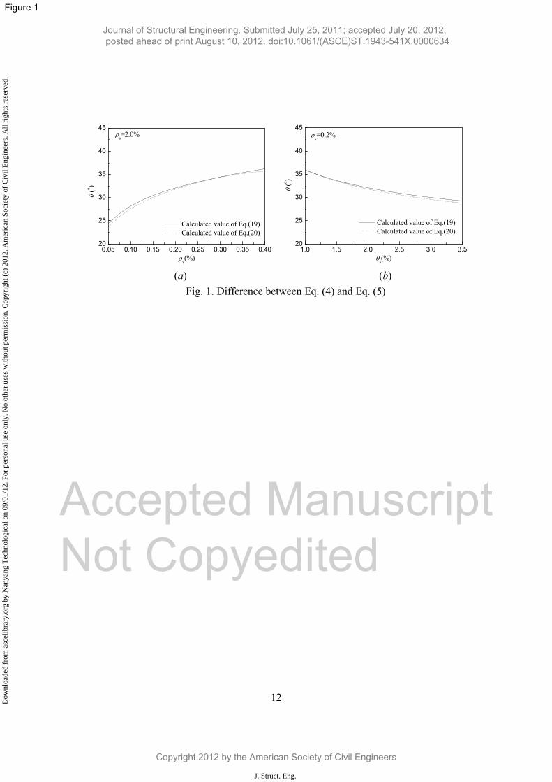
Rationality of Simplified Equation of Calculating θ
Eq. (5) is derived based on the assumption of νc = 0.4ν, and the influence of the νc/ν value on θ is
discussed here. Substituting νc = 0.25ν into Eq. (3), we can get θ(νc = 0.25ν)/ θ(νc = 0.4ν) = 1.07; therefore,
there is little difference. Similarly, if νc = 0.6ν, the final value of θ has little change. In addition, Eq. (5)
is derived based on the assumption of the value of θ in the right side of Eq. (4) being 35°. Fig. 1 shows
the differences between the calculated values of Eq. (4) and Eq. (5), in which, n = Es/Ec = 6.0, and the
calculated value of Eq. (5) is very close to that of Eq. (4). Hence, Eq. (5) can be utilized to calculate θ.
Solution Algorithm for Shear Strength
At shear failure when stirrups yield, the Mohr’s circle of concrete average strain can be used to calculate
the tensile strain ε1, as given below:
2
1 2
2
cos 2 1y
(6)
The principal compressive strain in concrete ε2 is related to both the principal compressive stress f2 and
the principal tensile strain ε1 in the manner (Vecchio and Collins 1986). The step-by-step solution
process is summarized in the flowchart shown in Fig. 2, and the formulas for calculating Vs, f1, f2, ω,
vci,max, f1,max can be found in the MCFT (Collins and Mitchell 1991).
Comparison with experimental results
The validation of the proposed truss approach is demonstrated by comparison with published
experimental results from previous investigations with respect to the shear strength at this state. There
are 209 rectangular beams with stirrups with λ ≥ 2.4 (Kim 2004; El-Metwally 2004; Lu 2007). These
beams encompass a wide range of sizes and material properties, and all the selected beams are shear-
Journal of Structural Engineering. Submitted July 25, 2011; accepted July 20, 2012; posted ahead of print August 10, 2012. doi:10.1061/(ASCE)ST.1943-541X.0000634
Copyright 2012 by the American Society of Civil Engineers
J. Struct. Eng.
Dow
nloa
ded
from
asc
elib
rary
.org
by
Nan
yang
Tec
hnol
ogic
al o
n 09
/01/
12. F
or p
erso
nal u
se o
nly.
No
othe
r us
es w
ithou
t per
mis
sion
. Cop
yrig
ht (
c) 2
012.
Am
eric
an S
ocie
ty o
f C
ivil
Eng
inee
rs. A
ll ri
ghts
res
erve
d.
Accep
ted M
anus
cript
Not Cop
yedit
ed
6
critical flexural members. The experimental database based on the 209 beams with stirrups was used to
evaluate the proposed method. The calculated shear strengths by the proposed method and experimental
results are compared as shown in Fig. 3. The mean ratio of the experimental to predicted strength and its
coefficient of variation are 1.204 and 0.207 for the proposed iterative method, showing a good
correlation between the proposed method and the experimental data. Most importantly, the analytical
results based on the proposed method are on the safer side as illustrated in Fig. 3, as the dowel action
and shear carried by the compression zone in the concrete contribution were not taken into account.
Determination of Principal Tensile Strain, ε1
The calculation method described above for shear strength requires a program to resolve the iterative
computations, which is complex for practical use. Eq. (1) can be used to calculate Vc explicitly; however,
there is still an unknown, ε1. The method to resolve the inclined crack width provides us with the
information that there is a relation between ε1 and εz. There are many methods to calculate the inclined
crack width, and all are related to the strains of stirrups. Sudhira (2008) compared the predicted inclined
crack width with the experimental data, and concluded that:
w m zk s (7)
where kw is the coefficient for the effect of the web reinforcement angle, and is equal to 1.2 for vertical
stirrups. Comparing Eq. (7) with ω = ε1smθ (Collins and Mitchell 1991), we get ε1 = 1.2εz. Eq. (1)
indicates that it will be unsafe for design if ε1 is taken to be small. For this reason, using the program
shown in Fig. 2, based on the database of 209 rectangular beams with stirrups, the calculated mean value
of ε1/εy is equal to 1.34, and its coefficient of variation is 0.08. The relation, ε1/εy=1.35, is used in this
paper to simplify calculation. Therefore, Eq. (1) is changed to:
Journal of Structural Engineering. Submitted July 25, 2011; accepted July 20, 2012; posted ahead of print August 10, 2012. doi:10.1061/(ASCE)ST.1943-541X.0000634
Copyright 2012 by the American Society of Civil Engineers
J. Struct. Eng.
Dow
nloa
ded
from
asc
elib
rary
.org
by
Nan
yang
Tec
hnol
ogic
al o
n 09
/01/
12. F
or p
erso
nal u
se o
nly.
No
othe
r us
es w
ithou
t per
mis
sion
. Cop
yrig
ht (
c) 2
012.
Am
eric
an S
ocie
ty o
f C
ivil
Eng
inee
rs. A
ll ri
ghts
res
erve
d.

Accep
ted M
anus
cript
Not Cop
yedit
ed
7
1 2 c0.18 ' 0.33 cotmin ,
32.4 1 1 6750.31sin cos16
c v vc
y y s
g s
x
f bd bd fV
f f Ea E
s s
(8)
Evaluations of Shear Methodologies based on Shear Database
Based on the database of 209 rectangular beams with stirrups, the mean ratio of the experimental to
predicted strength and its coefficient of variation are 1.204 and 0.207, 1.213 and 0.214, 1.405 and 0.256,
and 1.394 and 0.228 for the proposed iterative method and simplified method, and the sectional design
methods in ACI 318R-08 and CSA-04 respectively. Comparison of the available models with
experimental data indicates that the proposed approach produces better mean ratios of the experimental
to predicted strength than others. The methods in ACI 318R-08 and CSA-04 lead to very conservative
results when compared with experimental tests of shear-critical RC beams. Also, good correlation
between the experimental and predicted strengths across the range of fc′, dv, λ, ρs, and ρvfyv is found,
which indicates that the proposed approach represents the effects of these key parameters very well.
Conclusions
In this study, a theoretical method to compute the inclination of struts and predict the shear strength of
RC beams is proposed based on MCFT. First, the expression of θ is rationally derived as shown by Eq.
(5), accounting for the contribution of the tensile stresses in the concrete between the cracks based on
MCFT. A program is then developed to calculate the shear strength. However, the iterative computations
are complicated and time-consuming. Associating the calculation of shear crack width with the
relationship between the principal tensile strain ε1 and the strain of stirrups εz, a simplified explicit
expression for Vc (shown by Eq. (8)) is given which does not require reference to a table or iterative
computations.
A shear database is compiled for slender shear-critical beams with λ ≥ 2.4, which is utilized to
evaluate the present approach, and the methods in ACI 318R-08, CSA-04. There is a good correlation
Journal of Structural Engineering. Submitted July 25, 2011; accepted July 20, 2012; posted ahead of print August 10, 2012. doi:10.1061/(ASCE)ST.1943-541X.0000634
Copyright 2012 by the American Society of Civil Engineers
J. Struct. Eng.
Dow
nloa
ded
from
asc
elib
rary
.org
by
Nan
yang
Tec
hnol
ogic
al o
n 09
/01/
12. F
or p
erso
nal u
se o
nly.
No
othe
r us
es w
ithou
t per
mis
sion
. Cop
yrig
ht (
c) 2
012.
Am
eric
an S
ocie
ty o
f C
ivil
Eng
inee
rs. A
ll ri
ghts
res
erve
d.
Accep
ted M
anus
cript
Not Cop
yedit
ed
8
between the shear strengths obtained by the proposed simplified method and the published experimental
data, with the average ratio of experimental to predicted shear strength of the 209 RC rectangular beams
and its coefficient of variation being 1.213 and 0.214. The proposed method therefore provides a
potential alternative to the existing techniques.
Journal of Structural Engineering. Submitted July 25, 2011; accepted July 20, 2012; posted ahead of print August 10, 2012. doi:10.1061/(ASCE)ST.1943-541X.0000634
Copyright 2012 by the American Society of Civil Engineers
J. Struct. Eng.
Dow
nloa
ded
from
asc
elib
rary
.org
by
Nan
yang
Tec
hnol
ogic
al o
n 09
/01/
12. F
or p
erso
nal u
se o
nly.
No
othe
r us
es w
ithou
t per
mis
sion
. Cop
yrig
ht (
c) 2
012.
Am
eric
an S
ocie
ty o
f C
ivil
Eng
inee
rs. A
ll ri
ghts
res
erve
d.

Accep
ted M
anus
cript
Not Cop
yedit
ed
9
References
American Association of State Highway and Transportation Officials (AASHTO). (2004). “LRFD
bridge design specifications.” 3rd Ed., Washington D.C.
American Concrete Institute (ACI). (2008). “Building code requirements for structural concrete and
Commentary.” ACI 318R-08. Farmington Hills, Mich.
ASCE-ACI Committee 426. (1973). “Shear strength of reinforced concrete members.” Journal of
Structural Engineering, ASCE, 99 (6), 1091-1187.
ASCE-ACI Committee 445. (1998). “Recent approaches on shear design of structural concrete.” Journal
of Structural Engineering, ASCE, 124(12), 1375-417.
Canadian Standards Association (CSA). (2004). “CAN CSA A23.3-04 Design of Concrete Structures.”
Rexdale, Canada.
Collins, M. P. and Mithell, D. (1991). Prestressed concrete structures, Prentice-Hall, Englewood Cliffs,
NJ.
Kassian, W.A. (1990). “Concrete contribution to shear strength in slender beams.” Ph.D. Thesis,
University of Alberta, Alberta, USA.
Kim K. S. (2004). “Shear Behavior of reinforced concrete beams and prestressed concrete beams.” Ph.D.
Thesis, University of Illinois at Urbana-Champaign, Urbana, Illinois.
Li, B and Tran C.T.N (2008) “Reinforced Concrete Beam Analysis supplementing Concrete
Contribution in Truss Models”, Engineering Structures, Vol.30 No.11 pp.3285-3294
Li, B and Tran C.T.N (2012) "Determination of Inclination of Strut and Shear Strength using Variable
Angle Truss Model for Shear-Critical RC Beams” Structural Engineering and Mechanics Vol. 41,
No. 4 pp.459-477
Lu, Y. (2007). “Theoretical and experimental research on shear capacity of high strength concrete beams
with high strength stirrups.” Ph.D. thesis, Hunan University, Changsha, China.
El-Metwally, A.S. (2004). “Shear strength of reinforced and PC beams using shear friction.” Ph.D.
Thesis, Calgary University, Alberta, Canada.
Journal of Structural Engineering. Submitted July 25, 2011; accepted July 20, 2012; posted ahead of print August 10, 2012. doi:10.1061/(ASCE)ST.1943-541X.0000634
Copyright 2012 by the American Society of Civil Engineers
J. Struct. Eng.
Dow
nloa
ded
from
asc
elib
rary
.org
by
Nan
yang
Tec
hnol
ogic
al o
n 09
/01/
12. F
or p
erso
nal u
se o
nly.
No
othe
r us
es w
ithou
t per
mis
sion
. Cop
yrig
ht (
c) 2
012.
Am
eric
an S
ocie
ty o
f C
ivil
Eng
inee
rs. A
ll ri
ghts
res
erve
d.

Accep
ted M
anus
cript
Not Cop
yedit
ed
10
Sudhira, D. S., Hiroshi, M. and Eakarat, W. (2008). “Evaluation of shear crack with in I-shaped
prestressed reinforced concrete beams.” Journal of Advanced Concrete Technology, 6(3), 443-458.
Vecchio, F. J. and Collins, M.P. (1986). “The modified compression field theory for reinforced concrete
elements subjected to shear.” ACI Journal Proceedings, 83(2), 219-231.
Journal of Structural Engineering. Submitted July 25, 2011; accepted July 20, 2012; posted ahead of print August 10, 2012. doi:10.1061/(ASCE)ST.1943-541X.0000634
Copyright 2012 by the American Society of Civil Engineers
J. Struct. Eng.
Dow
nloa
ded
from
asc
elib
rary
.org
by
Nan
yang
Tec
hnol
ogic
al o
n 09
/01/
12. F
or p
erso
nal u
se o
nly.
No
othe
r us
es w
ithou
t per
mis
sion
. Cop
yrig
ht (
c) 2
012.
Am
eric
an S
ocie
ty o
f C
ivil
Eng
inee
rs. A
ll ri
ghts
res
erve
d.
Accep
ted M
anus
cript
Not Cop
yedit
ed
11
Notations
ag Maximum aggregate size
b Web width
dv Effective shear depth taken as flexural lever arm which needs not be
taken less than 0.9d
Ec Modulus of elasticity of concrete
f1 Principal tensile stress in cracked concrete
f2 Principal compressive stress in cracked concrete
fc′ Cylinder strength of concrete fci Compressive stress on crack surface (assumed as zero in this model) fsx Tensile stress in the longitudinal steels fsz Tensile stress in the transverse steels
fy Yielding stress of longitudinal reinforcing steels
fvy Yielding stress of transverse reinforcing steels
n ratio of modulus of elasticity of reinforcing steels to modulus of
elasticity of concrete, = Es/Ec
s Spacing of stirrups
sx Vertical spacing of longitudinal bars distributed in the web
Vc Contribution of concrete to shear
Vs Contribution of stirrups to shear
α1
Factor accounting for bond characteristics of reinforcement, α1=1.0 for
deformed bars, α1=0.7 for plain bars, wires or bonded strands, α1=0 for
unbonded reinforcement
α2 Factor accounting for sustained or repeated loading, α2=1.0 for short-
term monotonic loading, α2=0.7 for sustained and/or repeated loads
ε1 Principal tensile strain in cracked concrete
ε2 Principal compressive strain in cracked concrete
εx Tensile strain in the longitudinal steels
εz Tensile strain in the transverse steels
θ Angle of the inclined strut in cracked concrete with respect to
longitudinal axis of member in variable truss model
Journal of Structural Engineering. Submitted July 25, 2011; accepted July 20, 2012; posted ahead of print August 10, 2012. doi:10.1061/(ASCE)ST.1943-541X.0000634
Copyright 2012 by the American Society of Civil Engineers
J. Struct. Eng.
Dow
nloa
ded
from
asc
elib
rary
.org
by
Nan
yang
Tec
hnol
ogic
al o
n 09
/01/
12. F
or p
erso
nal u
se o
nly.
No
othe
r us
es w
ithou
t per
mis
sion
. Cop
yrig
ht (
c) 2
012.
Am
eric
an S
ocie
ty o
f C
ivil
Eng
inee
rs. A
ll ri
ghts
res
erve
d.

Accep
ted M
anus
cript
Not Cop
yedit
ed
12
λ Shear span to effective depth of section
ν Applied shear stress
νc Contribution of concrete to shear stress, equals to Vc/(bdv)
νci,max Maximum shear stress on a crack given width can resist
ρs Ratio of area of longitudinal reinforcement to beam effective sectional
area
ρv Ratio of volume of shear reinforcement to volume of concrete core
measured to outside of Stirrups
ω Crack width
Journal of Structural Engineering. Submitted July 25, 2011; accepted July 20, 2012; posted ahead of print August 10, 2012. doi:10.1061/(ASCE)ST.1943-541X.0000634
Copyright 2012 by the American Society of Civil Engineers
J. Struct. Eng.
Dow
nloa
ded
from
asc
elib
rary
.org
by
Nan
yang
Tec
hnol
ogic
al o
n 09
/01/
12. F
or p
erso
nal u
se o
nly.
No
othe
r us
es w
ithou
t per
mis
sion
. Cop
yrig
ht (
c) 2
012.
Am
eric
an S
ocie
ty o
f C
ivil
Eng
inee
rs. A
ll ri
ghts
res
erve
d.

Accep
ted M
anus
cript
Not Cop
yedit
ed
Captions to Figures Fig. 1. Difference between Eq. (4) and Eq. (5)
Fig. 2. Flowchart showing solution algorithm for shear strength
Fig. 3. Correlation of experimental and predicted shear strength based on proposed method
Journal of Structural Engineering. Submitted July 25, 2011; accepted July 20, 2012; posted ahead of print August 10, 2012. doi:10.1061/(ASCE)ST.1943-541X.0000634
Copyright 2012 by the American Society of Civil Engineers
J. Struct. Eng.
Dow
nloa
ded
from
asc
elib
rary
.org
by
Nan
yang
Tec
hnol
ogic
al o
n 09
/01/
12. F
or p
erso
nal u
se o
nly.
No
othe
r us
es w
ithou
t per
mis
sion
. Cop
yrig
ht (
c) 2
012.
Am
eric
an S
ocie
ty o
f C
ivil
Eng
inee
rs. A
ll ri
ghts
res
erve
d.
12
0.05 0.10 0.15 0.20 0.25 0.30 0.35 0.4020
25
30
35
40
45
(o )
v(%)
Calculated value of Eq.(19) Calculated value of Eq.(20)
s=2.0%
1.0 1.5 2.0 2.5 3.0 3.5
20
25
30
35
40
45
(o )
s(%)
Calculated value of Eq.(19) Calculated value of Eq.(20)
v=0.2%
(a) (b)
Fig. 1. Difference between Eq. (4) and Eq. (5)
Accepted Manuscript Not Copyedited
Journal of Structural Engineering. Submitted July 25, 2011; accepted July 20, 2012; posted ahead of print August 10, 2012. doi:10.1061/(ASCE)ST.1943-541X.0000634
Copyright 2012 by the American Society of Civil Engineers
J. Struct. Eng.
Dow
nloa
ded
from
asc
elib
rary
.org
by
Nan
yang
Tec
hnol
ogic
al o
n 09
/01/
12. F
or p
erso
nal u
se o
nly.
No
othe
r us
es w
ithou
t per
mis
sion
. Cop
yrig
ht (
c) 2
012.
Am
eric
an S
ocie
ty o
f C
ivil
Eng
inee
rs. A
ll ri
ghts
res
erve
d.

13
Input beam parameters
Calculate angle of diagonal strut using Eq.(5)
Calculate contribution of stirrups Vs
Assume 2
Calculate 1 using Eq.(6)
Calculate f2
estimate crack width
Calculate ci,max
Vc1=?Vc2
No
Vc=Vc1
Yes
V=Vc+Vs
Calculate f1
Transmitting ability f1,max
f1=min(f1,f1,max)
V2c=f1bdvcot V1c=(f1+f2)bdvsin cos -Vs
Fig. 2. Flowchart showing solution algorithm for shear strength
Acc
epte
d M
anus
crip
t N
ot C
opye
dite
d
Journal of Structural Engineering. Submitted July 25, 2011; accepted July 20, 2012; posted ahead of print August 10, 2012. doi:10.1061/(ASCE)ST.1943-541X.0000634
Copyright 2012 by the American Society of Civil Engineers
J. Struct. Eng.
Dow
nloa
ded
from
asc
elib
rary
.org
by
Nan
yang
Tec
hnol
ogic
al o
n 09
/01/
12. F
or p
erso
nal u
se o
nly.
No
othe
r us
es w
ithou
t per
mis
sion
. Cop
yrig
ht (
c) 2
012.
Am
eric
an S
ocie
ty o
f C
ivil
Eng
inee
rs. A
ll ri
ghts
res
erve
d.

14
0 500 1000 1500 2000 25000
500
1000
1500
2000
2500
V exp(k
N)
Vpre(kN)
Mean(Vexp/Vpre=1.204)Std=0.250, CoV=0.207
Fig. 3. Correlation of experimental and predicted shear strength based on proposed method
Accepted Manuscript Not Copyedited
Journal of Structural Engineering. Submitted July 25, 2011; accepted July 20, 2012; posted ahead of print August 10, 2012. doi:10.1061/(ASCE)ST.1943-541X.0000634
Copyright 2012 by the American Society of Civil Engineers
J. Struct. Eng.
Dow
nloa
ded
from
asc
elib
rary
.org
by
Nan
yang
Tec
hnol
ogic
al o
n 09
/01/
12. F
or p
erso
nal u
se o
nly.
No
othe
r us
es w
ithou
t per
mis
sion
. Cop
yrig
ht (
c) 2
012.
Am
eric
an S
ocie
ty o
f C
ivil
Eng
inee
rs. A
ll ri
ghts
res
erve
d.