Embed Size (px)
Citation preview
TEM Journal. Volume 9, Issue 4, Pages 1475‐1479, ISSN 2217‐8309, DOI: 10.18421/TEM94‐20, November 2020.
TEM Journal – Volume 9 / Number 4 / 2020. 1475
Evaluation of Stainless Steel AISI 316Ti Corner Joints Quality Produced by
Tungsten Inert Gas Welding
Dominika Botkova 1,2, Frantisek Botko 1, Zuzana Mitalova 1, Vladimir Simkulet 1, Maros Somsak 1
1The Technical University of Kosice, Faculty of Manufacturing Technologies with a seat in Presov, Bayerova 1, 080 01 Presov, Slovak Republic
2The Czech Academy of Sciences, Institute of Geonics, Studentska 1768, 708 00 Ostrava – Poruba, Czech Republic
Abstract –Welding is one of the most common ways of creating permanent joints in various industries. It is important to constantly look for ways to increase the quality of welds and look for optimal conditions to achieve a quality joint. The presented article is focused on the evaluation of the quality of weldments made of AISI 316Ti material created by TIG technology with additional material and without additional material. The parameter that changed was the welding current. HV hardness measurements and macroscopic weld evaluation were used to evaluate the quality of the welded joint.
Keywords –welding, stainless steel, welding current, hardness, quality.
1. Introduction
Welding technology is an inseparable method of joining, and it is used in a large number of industrial applications, not only in the engineering industry. The joint is formed under the action of heat [1] pressure, with or without additional material.
DOI: 10.18421/TEM94‐20 https://doi.org/10.18421/TEM94-20
Corresponding author: Frantisek Botko, The Technical University of Kosice, Faculty of Manufacturing Technologies with a seat in Presov, Bayerova 1, 080 01 Presov, Slovak Republic. Email: [email protected]
Received: 25 September 2020. Revised: 26 October 2020. Accepted: 02 November 2020. Published: 27 November 2020.
© 2020 Dominika Botkova et al; published by UIKTEN. This work is licensed under the Creative Commons Attribution‐NonCommercial‐NoDerivs 4.0 License.
The article is published with Open Access at www.temjournal.com
Its widespread use in various fields requires a constant thorough examination of welded joints. Great emphasis is placed mainly on its safety, so it is important to evaluate the quality of the welded joint by various methods [2],[3].
The welded joint can be made by fusion and pressure, or by a combination of both. During fusion welding, the base material to which the additional material is added melts. Fusion welding can be created by electric arc, flame, plasma, electron, and laser beam. Pressure welding is a joint created by heating and joining the contact surfaces [4]. Pressure welding includes friction welding, resistance welding [5], cold pressure welding, diffusion, and ultrasonic welding.
Electric arc welding is the most common in practice [6]. The heat source is an electric arc, which is characterized as an electric discharge in a gas passing between two oppositely charged electrodes (the welded material has a positive pole and the filler material has a negative pole). During the process, the contact surfaces [7] of the material are melted, where additional material is added to the molten metal. The process takes place at a temperature of 5000 to 8000 °C [8]. Arc welding is divided into MIG (Metal Inert Gass), MAG (Metal Active Gass), TIG (Tungsten Inert Gass) welding, and manual welding with a coated electrode (SMAW).
In the case of MIG / MAG welding, it is an arc welding in a protective gas atmosphere. MIG welding uses an inert gas (argon, helium) and the gases do not react chemically with the molten bath. In MAG welding, a mixture of active gases (argon, carbon dioxide, and oxygen, or a mixture of argon and carbon dioxide) is used, which chemically reacts with the molten bath.
TIG welding is electric arc welding with a non-melting tungsten electrode [9], where an inert gas is constantly supplied to the melting bath. An electric arc is created between the tungsten electrode and the
TEM Journal. Volume 9, Issue 4, Pages 1475‐1479, ISSN 2217‐8309, DOI: 10.18421/TEM94‐20, November 2020.
1476 TEM Journal – Volume 9 / Number 4 / 2020.
welded material. Welding is possible without and with the addition of filler (additional) material. When welding without the use of filler material, the electric arc melts the contact surfaces of the welded parts, which merge into each other and form a heterogeneous joint [10]. When using the filler material, the added material flows deep into the welded part and thus forms a joint [11], [12]. The filler material may be in the form of a wire or a piece of filler material. It is added to the weld pool by the operator holding it in his hand or via a cable guide which pushes it into an electric arc. The welding process takes place in the constant presence of inert gas - argon, which protects the welding bath from the presence of air and helps ignite the electric arc.
The advantages of TIG welding are control over the created weld pool, the possibility of welding even without additional material, the additional material can be in the form of a stick, greater depth of weld, the possibility of welding high-alloy steels and thin materials [13], [14]. Disadvantages include high demands on the welding equipment [15] and the associated higher cost of the equipment [16], lower welding speed, and increased demands on operator skill.
The presented paper aimed to determine the suitable welding current for welding stainless steel EN 1.4571 and to determine the difference in hardness according to Vickers between the base material, heat-affected zone (HAZ), and weld metal. The research consisted of evaluating the quality [17] of a welded joint made using TIG technology. Hardness [18] was assessed in three areas - in the base material, in the heat-affected zone, and the weld metal.
2. Experimental Methodology 2.1. Experimental Material
The experimental material was austenitic
(chromium-nickel-molybdenum) steel 1.4571 (AISI 316Ti) stabilized by the addition of titanium (Table 1). The material has higher yield strength / tensile strength, Mo additive - ensures high corrosion resistance. AISI 316Ti steel is difficult to polish (caused by the mentioned additive Ti), hardenable and non-magnetic. The material is resistant to acids (except HNO3 acid) - it is suitable to apply it to aggressive environments. The material is well formable (suitable operations - deep drawing, bending). It can be applied for short periods up to temperatures of 800-900 °C, for long periods up to temperatures of 400 °C. Applications: chemical, construction (mechanically stressed structures), pharmaceutical, shipbuilding, and food industries. It is used in the production of pressure vessels, pipes, chimneys, welded structures, and in the production of components for swimming pools, and its use is also suitable in the conditions of the marine environment.
Table 1.Material composition and material properties of AISI 316Ti
2.2. Experimental Procedure
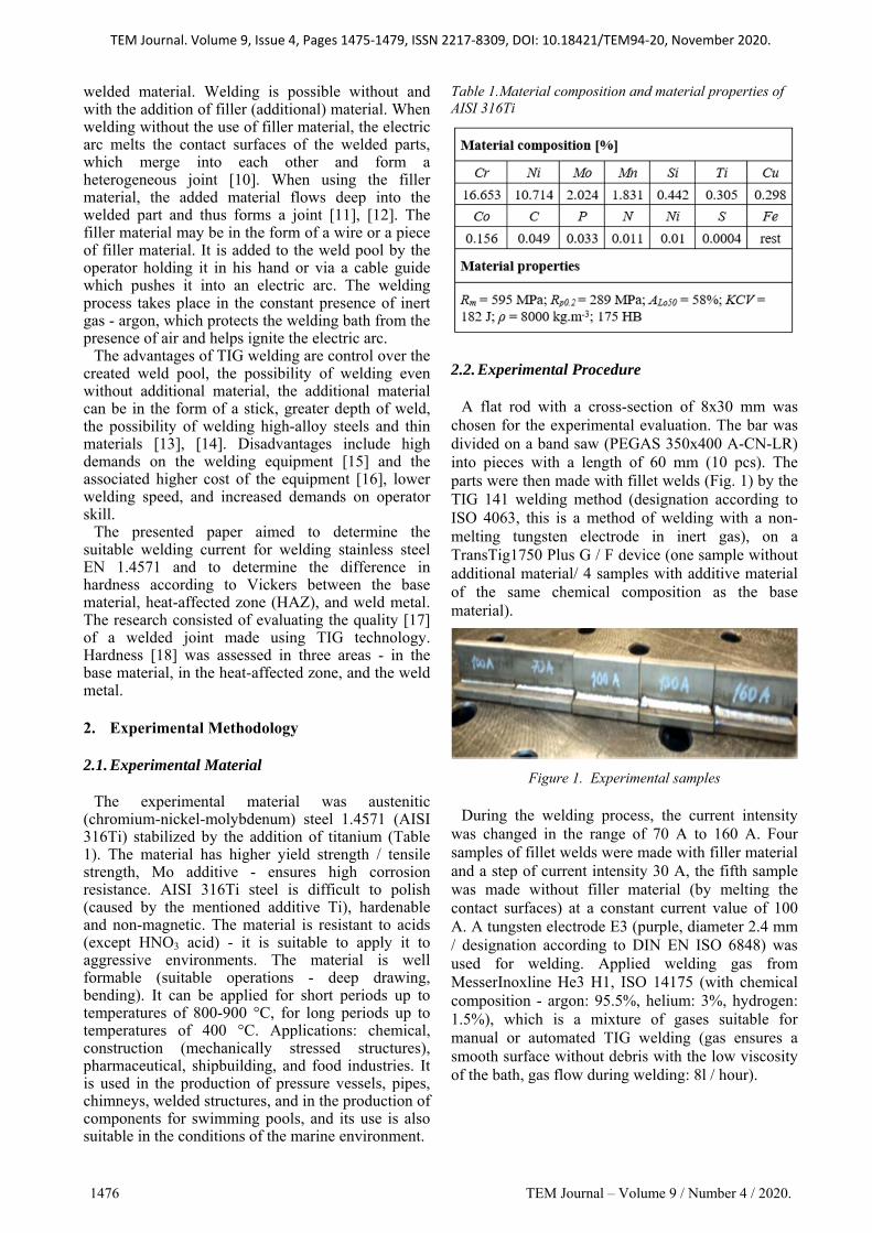
A flat rod with a cross-section of 8x30 mm was chosen for the experimental evaluation. The bar was divided on a band saw (PEGAS 350x400 A-CN-LR) into pieces with a length of 60 mm (10 pcs). The parts were then made with fillet welds (Fig. 1) by the TIG 141 welding method (designation according to ISO 4063, this is a method of welding with a non-melting tungsten electrode in inert gas), on a TransTig1750 Plus G / F device (one sample without additional material/ 4 samples with additive material of the same chemical composition as the base material).
Figure 1. Experimental samples
During the welding process, the current intensity was changed in the range of 70 A to 160 A. Four samples of fillet welds were made with filler material and a step of current intensity 30 A, the fifth sample was made without filler material (by melting the contact surfaces) at a constant current value of 100 A. A tungsten electrode E3 (purple, diameter 2.4 mm / designation according to DIN EN ISO 6848) was used for welding. Applied welding gas from MesserInoxline He3 H1, ISO 14175 (with chemical composition - argon: 95.5%, helium: 3%, hydrogen: 1.5%), which is a mixture of gases suitable for manual or automated TIG welding (gas ensures a smooth surface without debris with the low viscosity of the bath, gas flow during welding: 8l / hour).
TEM Journal. Volume 9, Issue 4, Pages 1475‐1479, ISSN 2217‐8309, DOI: 10.18421/TEM94‐20, November 2020.
TEM Journal – Volume 9 / Number 4 / 2020. 1477
2.3. Hardness Measurement and Macroscopic Analysis
To perform macroscopic analysis and subsequent
hardness measurement, the samples (Fig. 2) were cut transversely through a weld (splitting with a PEGAS 350x400 A-CNC-LR automatic saw), subsequently, the surface was machined by milling technology on 3-axis vertical CNC machine tool. Grinding and polishing were performed on a KOMPAKT 1031 device (sandpaper: SiC grit 380, 500, 800 / for fine sanding 1200, 2000, 4000). The samples were etched for 5-10 seconds. A Micro Hardness CV-400 DAT (indentation force 200 gf, load time 10 s) was used to measure the hardness. Hardness was assessed in three areas - in the base material, in the heat-affected zone, and in the weld itself. The measurement took place in the three mentioned areas with repeated 3x (in each place), then the average value was calculated.A macroscopic method (Dino-Lite Premier camera, DinoCapture 2.0 software) was applied to evaluate the quality of the welds, and the images were magnified 40 times
Figure 2. Sample prepare for measurement
3. Results 3.1. Measurement of Hardness HV Table 2. Results of hardness measurement
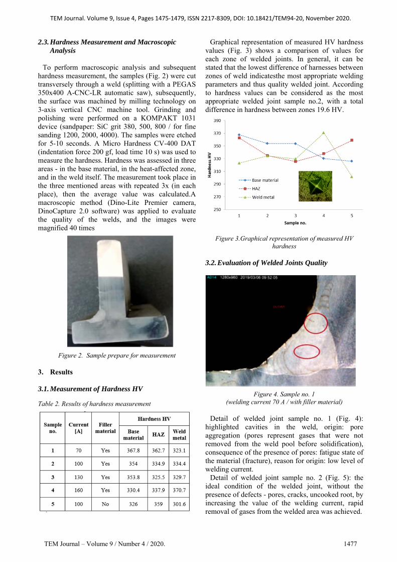
Graphical representation of measured HV hardness values (Fig. 3) shows a comparison of values for each zone of welded joints. In general, it can be stated that the lowest difference of harnesses between zones of weld indicatesthe most appropriate welding parameters and thus quality welded joint. According to hardness values can be considered as the most appropriate welded joint sample no.2, with a total difference in hardness between zones 19.6 HV.
Figure 3.Graphical representation of measured HV hardness
3.2. Evaluation of Welded Joints Quality
Figure 4. Sample no. 1 (welding current 70 A / with filler material)
Detail of welded joint sample no. 1 (Fig. 4):
highlighted cavities in the weld, origin: pore aggregation (pores represent gases that were not removed from the weld pool before solidification), consequence of the presence of pores: fatigue state of the material (fracture), reason for origin: low level of welding current.
Detail of welded joint sample no. 2 (Fig. 5): the ideal condition of the welded joint, without the presence of defects - pores, cracks, uncooked root, by increasing the value of the welding current, rapid removal of gases from the welded area was achieved.

TEM Journal. Volume 9, Issue 4, Pages 1475‐1479, ISSN 2217‐8309, DOI: 10.18421/TEM94‐20, November 2020.
1478 TEM Journal – Volume 9 / Number 4 / 2020.
Figure 5. Sample no. 2 (welding current 100 A / with filler material)
Figure 6. Sample no. 3 (welding current 130 A / with filler material)
Detail of welded joint sample no. 3 (Fig. 6):
incomplete penetration (at the bottom), cause: high welding speed caused by increased welding current.
Figure 7. Sample no. 4 (welding current 160 A / with filler material)
Weld joint detail Sample no. 4 (Fig. 7): incomplete penetration, the reason for the error similar to the previous case (for sample no. 3 in Fig. 6).
Figure 8. Sample no. 5 (welding current 100 A / without filler material)
Weld joint detail sample no. 5 (Fig. 8): in the case
of welding without additional material, consequence: sagging, overlapping weld (red lines represent the plane of the base material / delimiting the sagging of the weld). 4. Conclusions
The article was focused on the evaluation of the quality of welds made of AISI 316Ti material created by Tungsten inert gas technology. 4 welds were made using filler material at a welding current setting of 70 to 160 A in 30 A steps and one at 100 A without filler material.
The highest quality based on hardness and macroscopic analysis was achieved by the weld created with additional material at 100 A (sample 2);
At 70 A (sample 1) pores were visible in the weld, which is an undesirable condition;
Incomplete penetration was observed in welds generated with 130 and 160 A currents (samples 3 and 4);
At 100 A (sample 5) low reinforcement was observed.
TEM Journal. Volume 9, Issue 4, Pages 1475‐1479, ISSN 2217‐8309, DOI: 10.18421/TEM94‐20, November 2020.
TEM Journal – Volume 9 / Number 4 / 2020. 1479
Acknowledgments
This work was supported by the projects: KEGA no. 030TUKE-4/2018 - Popularization and transfer the strategy Industry 4.0 into the technical study programs focusing on secondary schools and project VEGA 1/0682/17 - Research, Development and Experimental Verification of Tool Prototype for Forming Rifled Tubes. References [1]. Winczek, J., Makles, K., Gucwa, M., Gnatowska, R.,
& Hatala, M. (2019). Calculation of Stresses during Shielded Arc Surfacing with Consideration Influence of Temperature and Structure Changes. In Industry 4.0: Trends in Management of Intelligent Manufacturing Systems (pp. 99-109). Springer, Cham.
[2]. Botko, F., Zajac, J., Czan, A., Radchenko, S., Lehocka, D., & Duplak, J. (2019, May). Influence of residual stress induced in steel material on Eddy currents response parameters. In International Scientific-Technical Conference MANUFACTURING (pp. 551-560). Springer, Cham
[3]. Boháčik, M., Mičian, M., Koňár, R., Trško, L., & Winczek, J. (2019). Ultrasonic Control of Ductile Cast Iron Castings by Phased Array Technique. Archives of Foundry Engineering.
[4]. Michal, P., Gombár, M., Vagaská, A., Piteľ, J., & Kmec, J. (2013). Experimental study and modeling of the zinc coating thickness. In Advanced Materials Research (Vol. 712, pp. 382-386). Trans Tech Publications Ltd.
[5]. Hlavatý, I., Hájková, P., Krejčí, L., & Čep, R. (2018). Electric resistance welding of austenitic and galvanized steel sheets. Tehnički vjesnik, 25(5), 1274-1277.
[6]. Hatala, M., Orlovský, I., & Radchenko, S. (2014). Influence of welding parameters to quality of welds from structural steel. In Key Engineering Materials (Vol. 581, pp. 287-291). Trans Tech Publications Ltd.
[7]. Petrů, J., Zlámal, T., Špalek, F., &Čep, R. (2018). Surface microhardening studies on steels after high feed milling. Advances in Science and Technology Research Journal, 12(2), 222–230.
[8]. Winczek, J., Gawronska, E., Murcinkova, Z., Hatala, M., Pavlenko, S., & Makles, K. (2017, March). Analysis of thermomechanical states in single-pass GMAW surfaced steel element. In AIP Conference Proceedings (Vol. 1822, No. 1, p. 020015). AIP Publishing LLC.
[9]. Kozak, J., Krejči, L., Hlavaty, I., Samardžić, I., & Čep, R. (2019). An analysis of structures occurring in weld deposit of steel S235JR+ N with tungsten carbide particles and martensitic matrix. Metalurgija, 58(3-4), 235-238.
[10]. Srivastava, M., Hloch, S., Krejci, L., Chattopadhyaya, S., Dixit, A. R., & Foldyna, J. (2018). Residual stress and surface properties of stainless steel welded joints induced by ultrasonic pulsed water jet peening. Measurement, 127, 453-462.
[11]. Krolczyk, J. B., Gapiński, B., Krolczyk, G. M., Samardžić, I., Maruda, R. W., Soucek, K., ... & Stas, L. (2016). Topographic inspection as a method of weld joint diagnostic. Tehnicki vjesnik, 23(1), 301-306.
[12]. Kumar, R., Chattopadhyaya, S., Dixit, A. R., Bora, B., Zelenak, M., Foldyna, J., ... & Sitek, L. (2017). Surface integrity analysis of abrasive water jet-cut surfaces of friction stir welded joints. The International Journal of Advanced Manufacturing Technology, 88(5-8), 1687-1701.
[13]. Michalik, P., Zajac, J., Fabianova, J., & Mital, D. (2017). The study of the surface quality of the thin wall bearing units to rolls roller seats pipe conveyor. Advances in Science and Technology Research Journal, 11.
[14]. Michalik, P., Zajac, J., Straka, Ľ., Nowakowski, L., & Ambrozy, M. (2018). Draft JIG structure design for measuring deformation of thin-walled robotic or conveyor components. Advances in Science and Technology Research Journal, 12.
[15]. Pollák, M., Török, J., Zajac, J., Kočiško, M., & Telišková, M. (2018, April). The structural design of 3D print head and execution of printing via the robotic arm ABB IRB 140. In 2018 5th International Conference on Industrial Engineering and Applications (ICIEA) (pp. 194-198). IEEE.
[16]. Petruš, M., Michalik, P., Straka, L., Hrabovsky, L., Macej, J., Tirpak, P., & Jusko, J. (2019). The evaluation of the production of the shaped part using the workshop programming method on the two-spindle multi-axis CTX alpha 500 lathe. Open Engineering, 9(1), 660-667.
[17]. Dobransky, J., & Hatala, M. (2007). Influence of selected technological parameter to quality parameters by injection molding. Annals of DAAAM & Proceedings, 223-225.
[18]. Lehocka, D., Botko, F., Klich, J., Sitek, L., Hvizdos, P., Fides, M., & Cep, R. (2020). Effect of pulsating water jet disintegration on hardness and elasticity modulus of austenitic stainless steel AISI 304L. The International Journal of Advanced Manufacturing Technology, 1-12.


![The studies of corrosion resistance of AISI 316Ti SS in ... · proposed by magnetoelectropolishing (MEP) [14-28], high-current-density electropolishing (HDEP) [29-31], or high-voltage](https://img.pdfslide.net/doc/110x75/5e6b0d7956a309405d66ccdd/the-studies-of-corrosion-resistance-of-aisi-316ti-ss-in-proposed-by-magnetoelectropolishing.jpg)