Embed Size (px)
Citation preview

ORNL/Sub/85-2202W 1
Evaluation of the Effects of NaturalGas Contaminants on Corrosion inCompressed Natural Gas Storage
Systems-Phase II
Fred F. Lyle, Jr.
Report Prepared bySouthwest Research Institute
6220 Culebra RoadSan Antonio, Texas 78284
under
Subcontract 86X-2202%
for
OAK RIDGE NATIONAL LABORATORYOak Ridge, Tennessee 37831
operated byMARTIN MARIETTA ENERGY SYSTEMS, INC.
for theU.S. DEPARTMENT OF ENERGY
Under Contract No. DE-AC05840R2 1400
OFFICE OF TRANSPORTATION SYSTEMSALTERNATIVE FUELS UTILIZATION PROGRAM

h
Printed in the United States of America. Available fromNational Technical Information Service
U.S. Department of Commerce5285 Port Royal Road, Springfield, Virginia 22161
NTIS price codes-Printed Copy: A05 Microfiche A01
This report was prepared as an account of work sponsored by an agency of theUnitedStatesGovernment. NeithertheUnitedStatesGovernment noranyagencythereof, nor any of their employees, makes any warranty, express or implied, orassumes any legal liability or responsibility for the accuracy, completeness, orusefulness, of any information, apparatus, product, or process disclosed, orrepresents that i ts usewould not infringe privately owned rights. Reference hereinto any specific commercial product, process, or service by trade name, trademark,manufacturer, or otherwise, does not necessarily constitute or imply itsendorsement, recommendation, or favoring by the United StatesGovernment orany agency thereof. The views and opinions of authors expressed herein do notnecessarily state or reflect those of theunited States Government or any agencythereof.

ORNL/Sub/85-22025/l
EVALUATION OF THE EFFECTS OF NATURAL GAS CONTAMINANTSON CORROSION IN COMPRESSED NATURAL GAS
STORAGE SYSTEMS - PHASE II
Fred F. Lyle, Jr.
Published Date - January 1989
Report Prepared bySouthwest Research Institute
6220 Culebra RoadSan Antonio, Texas 78284
underSubcontract 86X-22025C
for
OAK RIDGE NATIONAL LABORATORYOak Ridge, Tennessee 37831
operated byMARTIN MARIETTA ENERGY SYSTEMS, INC.
for theU.S. DEPARTMENT OF ENERGY
under contract DE-AC05-840R21400
OFFICE OF TRANSPORTATION SYSTEMSALTERNATIVE FUELS UTILIZATION PROGRAM

c

.
TABLE OF CONTENTS
ABSTRACT .......................................................
EXECUTIVE SUMMARY..............................................
LIST OF FIGURES . . . . . . . . . . . . . . . . . . . . . . . . . . . . . . . . . . . . . . . . . . . . . . . .
LIST OF TABLES .................................................
SECTION 1: INTRODUCTION .......................................
Background .................................................Objectives .................................................Scope of Work ............ ..F ...............................
Task l--Industry Contacts and Literature Review........Task Z--Experimental Program ...........................Task 3--Metallurgical Evaluation of Used CNG CylindersTask 4--Analyses .......................................
SECTION 2: SUMMARY OF PHASE I PROGRAM
Task l--Industry Contacts and Literature Review............Task e--Experimental Program ...............................
Materials and Procedures ...............................Gases ..............................................Alloys .............................................Test Methods .......................................Test Conditions ....................................Test Results .......................................
Stress Corrosion Cracking ......................General Corrosion..............................
Task 3--Evaluation of Used CNG Cylinders ...................Findings of the Phase I Program............................
SECTION 3: PHASE II PROGRAM
Objectives ...............................................Corrosion Test Program .....................................
Background .............................................Test Materials, Conditions, and Procedures .............Stress Corrosion Cracking Test Results .................
4130X Steel ........................................Baseline Test..................................H S EffectsC$ Effects
....................................
.. .... ....Coibined H2S and CO2 Effects.............................................
...111
Pagei
ii
ix
X
1
68
ii9
1:11
E1619
2122.2223
5;
S%3637

TABLE OF CONTENTS (Continued)
SECTION 3: PHASE II PROGRAM (Continued)
15830 Steel ........................................H S EffectsC6 Effects
....................................
.. .... ....Coibined H S and CO2 Effects
General Corrosion P.............................................
ests ................................4130X Steel ........................................15B30 Steel ........................................
Findings of Phase II Corrosion Test Results ................Stress Corrosion Crackins Tests ........................
Gene
SECTION 4:
Conclusi
4130X Steel ........................................15B30 Steel ........................................ral Corrosion......................................
CONCLUSIONS AND RECOMMENDATIONS .................... 48
ons ............................................... 4850505353545454
Recommendations ............................................Gas-Qua1 ity Standard ...................................Other Recommendations ..................................
Use of Normalized Steels in CNG Cylinders ..........Additional Research ....................................
Corrosion Fatigue . . . . . . . . . . . . . . . . . . . . . . . . . . . . . . . . . .Corrosion and Stress Corrosion Cracking ............
SECTION 5: REFERENCES . . . . . . . . . . . . . . . . . . . . . . . . . . . . . . . . . . . . . . . . . 55
383838424245
J 45
1:464747
F
iv

F i g u r e N o . T i t l e
1 Variation of reduction in area with testenvironments for 4130X steel slow-strain-rate specimens exposed in Phase I experi-mental program.
Page
13
LIST OF FIGURES
Variation of reduction in area with testenvironments for 6061-T6 aluminum alloyslow-strain-rate specimens exposed inPhase I experimental program.
14
3 Photomicrographs of typical fissuresfound in dome-shaped heads of some4130X steel CNG cylinders examinedin Phase I.
15
4 Sumnary of stress corrosion cracking testresults for 4130X steel exposed in H2S-containing solutions.
5 Sumnary of stress corrosion cracking testresults for 4130X steel exposed in CO2-containing solutions.
34
35
6 Sumnary of stress corrosion cracking testresultscontain
for 15B30 steel exposed in H2S-ing solutions.
40
7 Summary of stress corrosion cracking testresultscontain
for 15B30 steel exposed in C02-ing solutions.
41

-a

LIST OF TABLES
T a b l e N o . T i t l e Page
1 Chemical Compositions of TestMaterials
26
2 Heat Treatment Conditions for Steels 27Tested
3 Stress Corrosion Cracking Test Results 30for 4130X Steel
4 Stress Corrosion Cracking Tests on 4130X 33Steel in Different Heat-Treatment Condi-tions
5 Stress Corrosion Cracking Test Results 39for 15B30 Steel
6 l,OOO-Hr Corrosion Tests on 4130X Steel 43in C02-Saturated Water
7 l,OOO-Hr Corrosion Tests on 15B30 Steelin C02-Saturated Water
44
vii

.

f
ABSTRACT
This report describes a research program that was conducted to define
natural gas contaminant levels necessary to insure that internal
corrosion of compressed natural gas (CNG) cylinders does not
constitute a hazard over the lifetimes of the cylinders. A
literature search was performed and companies in the natural gas
transmission and distribution industries were contacted: :,to identify
and determine the composition ranges of contaminants in natural
gases; and to obtain information regarding corrosion damage of CNG
cylinders and cylinder materials. Corrosion and stress corrosion
cracking (SCC) tests were performed on the cylinder materials most
widely used in CNG cylinders in the United States (4130X and 15B30
steels and 6061-T6 aluminum alloy). Tests were conducted in:
natural gases from several producing wells and from an interstate
pipeline; and in aqueous solutions saturated with varying
concentrations of natural gas contaminants. Also, metallurgical
analyses of nine (eight steel and one aluminum),,used CNG cylinders
were performed.
Limiting concentrations of hydrogen sulfide (H$S), carbon dioxide
(CO*), and other CNG contaminants necessary to prevent internal
corrosion of CNG fuel and storage cylinders were defined. This
knowledge will minimize potential hazards of using CNG as a vehicle
fuel. It should also lead to reduced costs of CNG use, since it has
been shown that reduction of contaminants to the very low levels
currently specified by the U.S. Department of Transportation (DOT)
and the Canadian Transport Commission (CTC) is not necessary. A gas-
quality standard based on program results is recommended. The
National Fire Protection Association (NFPA) has adopted the
recommended gas-quality standard.
ix

k

3 EXECUTIVE SUbMARY
ilNatural gas suppliers, natural gas vehicle operators, and various
local, state, and federal government agencies are concerned about safe
operation of CNG vehicles, in particular with regard to the potential
of contaminants in natural gas to cause corrosion damage to internal
surfaces of CNG cylinders. In view of the possibility that
significant corrosion damage to CNG fuel cylinders could occur,
however small that possibility might be, a committee of the National
Fire Protection Association (NFPA) attempted in 1984 to define
allowable contaminant levels for CNG which are necessary to prevent
significant internal corrosion of CNG fuel cylinders and storage
cylinders. After investigating existing data and codes, the NFPA
committee concluded that sufficient technical data upon which to base
gas-quality standards did not exist.
This report describes a research project conducted at Southwest
Research Institute (SwRI) to provide the data needed to develop a gas-
quality standard for natural gases used as CNG. The project was
conducted in two parts. Phase I was jointly sponsored by the New York
State Energy Research and Development Authority (NYSERDA), Albany, NY,
and the New York Gas Group (NYGAS), New York, NY, an association of
gas companies operating in New York State. Phase II work was
supported by the U.S. Department of Energy (DOE) through a subcontract
with Martin Marietta Energy Systems, Inc., Oak Ridge, TN. The results
of Phase I have been reported separately. This report summarizes the
results of Phase I, and details the Phase II program.
The primary objective of the program was to define natural gas
concentration levels necessary to insure that internal corrosion of
CNG cylinders does not constitute a hazard over the lifetimes of the
cylinders. A literature search was performed and companies in the
natural gas transmission and distribution industries were contacted:
xi

to identify and determine the composition ranges of contaminants in
natural gases; and to obtain information regarding corrosion damage of
CNG cylinders and cylinder materials. Metallurgical analyses of nine
(eight steel and one aluminum) used CNG cylinders were performed.
Corrosion and stress corrosion cracking (SCC) tests were performed on
the cylinder materials most widely used in CNG cylinders in the United
States (4130X and 15B30 steels and 6061-T6 aluminum alloy). Corrosion
and SCC tests were conducted in: natural gases from several producing
wells and from an interstate pipeline; and in aqueous solutions
saturated with varying concentrations of hydrogen sulfide (H2S) and
carbon dioxide (COZ), the natural gas contaminants primarily
responsible for corrosion.
No environmentally induced cracking or significant corrosion damage
was found in any of the cylinders. None of the cylinder materials
were susceptible to SCC or to significant corrosive attack in the
absence of liquid water. Aluminum alloy 6061-T6 was immune to
corrosion and SCC in all aqueous environments tested, regardless of
the concentrations of H2S and CO2 present. Both 4130X and 15B30
steels were susceptible to SCC and corrosion in aqueous environments
containing H2S and/or CO*. The degree~'to which the steels were
susceptible to corrosion depends upon: the concentrations of H2S and
CO2 in the natural gas; the heat-treatment condition of the steel; and
the steel hardness. /
Conclusions drawn from program results are as follows:
. The principal corrosive contaminants in natural gases in theU.S. are H2S and other sulfur-containing species, CO*, oxygen,and water.
. Aluminum alloy 6061-T6 is suitable for use in CNG cylinders,regardless of the natural gas composition. Aluminum alloy6061-T6 is immune to stess corrosion cracking, embrittlement,and other forms of general and localized corrosion in naturalgas environments, including H2S and CO2 environments that arecapable of inducing cracking, embrittlement, pitting, andgeneral corrosion in steels.
xii

. Corrosion of CNG cylinders made of steel may be prevented bymaintaining the water vapor concentration of CNG gas suppliesbelow the dew point for the anticipated range of temperaturesand pressures. Steels are not subject to significantcorrosion in natural gas environments, regardless of theconcentrations of other contaminants, unless liquid water ispresent.
. Normalized 4130X steels are not suitable for use in CNGcylinders unless the water vapor concentration of the supplygas is sufficiently low to prevent condensation of liquidwater. Normalized HRC 21/22 4130 steel specimens cracked inenvironments containing as little as 0.05 psia H2S or 7.0 psiacop
. Quenched-and-tempered 4130X steels are suitable for use in CNGcylinders at hardnesses to HRC 25/26 for natural gas suppliesin which the H2S partial pressure is 0.15 psia or less and theCO2 concentration does not exceed 7 psia. In the absence ofCOP, quenched-and-tempered 4130X steel at a hardness of HRC29/30 is acceptable.
. Quenched-and-tempered 15830 steels are suitable for use in CNGcylinders at hardnesses to HRC 29/30 for natural gas suppliesin which the H2S partial pressure is 0.50 psia or less and theCO2 concentration does not exceed 7 psia.
The limitation of 7 psia CO2 for quenched-and-tempered 15B30 steels is
necessary to prevent general corrosion and pitting in these
materials. Higher levels of CO2 can be tolerated by quenched-and-
tempered 4130X steels without significant general corrosion or
pitting, but test results indicated a limit of 7 psia CO2 is
appropriate for these steels to minimize the possibility of stress
corrosion cracking.
These conclusions indicate that stress corrosion cracking is possible
in steel CNG cylinders for certain combinations of steels, heat
treatment conditions, hardnesses, and gas compositions. Since current
DOT regulations allow normalized steels to be used in CNG cylinders,
one of the most significant findings of the program is that normalized
4130 steels with hardnesses of HRC 21/22 can suffer stress corrosion
xiii

cracking at very low levels of H2S or C02, if liquid water also is
present.
Several of the eight used 4130X steel cylinders that were examined in
the program had hardnesses in excess of HRC 21/22 and microstructures
that were not fully quenched and tempered. The absence of significant
corrosion in these cylinders, particularly the absence of crack growth
from large fabrication flaws found in several of the cylinders,
suggests that CNG supplies currently being used in the U.S. have very
low levels of H2S and C02, or the typical water vapor concentration of
the gases used in the cylinders examined was very low. Analyses of
natural gases obtained from wells, pipelines, and distribution systems
are consistent with this observation. With the exception of water,
which was very high in a few gases from distribution lines, corrosive
contaminants in the gases analyzed were well within limits established
by DOT for CNG supplies.
The results of the program were used to develop a gas-quality standard
for CNG that is sufficient to prevent internal corrosion of CNG
cylinders without being economically impractical. The recommended
standard incorporates three options, depending upon the CNG cylinder
material used and the manner in which CNG suppliers choose to control
gas compositions, as follows:
. Aluminum Cylinders. No restrictions on the concentrations ofcorrosive contaminants in natural gas are required for CNGcylinders made of aluminum alloy 6061-T6.
. Steel Cylinders. When the dew point of the natural gasentering a steel CNG cylinder is below the lowest anticipatedcylinder temperature at the highest anticipated cylinderpressure, no limitations are required on the concentrations ofother corrosive contaminants in the gas; or
t. Steel Cylinders. When the dew point of the natural gas eh
entering a steel CNG cylinder is not below the lowest'6
anticipated cylinder temperature at the highest anticipatedcylinder pressure, the gas-quality in the cylinder shallcomply with the following limitations on corrosive econtaminants:
xiv

/. ...~.“l.-.l.-.-.~_.l .--.,. _-^-.^ __X._-r__ _.;. _
Hydrogen Sulfide (H2S) and 'Other Soluble Sulfides--O.05 psiapartial pressure, maximum.
Carbon dioxide (C021--7.0 psia partial pressure, maximum.
Oxygen--O.5 volume percent, maximum.
Water Vapor--7 lb/MMCF, maximum.
This recommended standard has been adopted by the National Fire
Protection Association (NFPA).
As noted earlier, the results of the experimental test program
revealed that SCC and embrittlement of normalized 4130X steels at a
hardness of HRC 21/22 is possible at very low levels of H2S and C02,
and that quenched-and-tempered steels of the same composition are not
susceptible to cracking and embrittlement at significantly higher
hardnesses and H2S levels. In view of these results, it is
recommended that 49 CFR 178.37, and other standards applicable to CNG
cylinders, be amended to prohibit the use of normalized steels in new
CNG cylinders. Consideration should also be given to requiring that
such cylinders be removed from CNG service or to requiring more
frequent inspection of normalized steel cylinders.
xv

4
J
Section 1
INTRODUCTION
BACKGROUND.
Compressed natural gas (CNG) has been used as a vehicular fuel for
more than 30 years in Italy, and there are over 300,000 CNG-fueled
vehicles operating there now (I).* Canada and New Zealand also are
rapidly developing CNG vehicle fleets, and in the United States there
are more than 30,000 dual-fuel vehicles which can be operated on
either CNG or gasoline (2). In all of these instances CNG has been
used safely. There have been no reported cases of CNG fuel cylinder
failures anywhere in the world. Further, no evidence of significant
corrosion or corrosion-related damage (e.g., stress corrosion cracking
(SCC), corrosion fatigue, or hydrogen embrittlement) to fuel cylinders
has been reported in the U.S., although small cracks of unknown origin
were found in some Italian fuel cylinders.
Natural gas suppliers, natural gas vehicle operators, and variousa.
local, state, and'federal government agencies are concerned about safe
operation of CNG vehicles, in particular with regard to the potential
a of contaminants in natural gas to cause corrosion damage to internal
surfaces of CNG cylinders. In view of the possibility that
significant corrosion damage to CNG fuel cylinders could occur,
however small that possibility might be, a committee of the National
Fire Protection Association (NFPA) attempted in 1984 to define
allowable contaminant levels for CNG which prevent significant
internal corrosion of CNG fuel cylinders and storage cylinders. After
investigating existing data and codes, the NFPA committee concluded
that sufficient technical data upon which to base gas-quality
standards did not exist.
(*)Underlined numerals in parentheses refer to references given inSection 5.

2
This report details a portion of a research project conducted at
Southwest Research Institute (SwRI) to provide the data needed to
develop a gas-quality standard for natural gases to be used as CNG.
The project was conducted in two parts. Phase I was jointly sponsored
by the New York State Energy Research and Development Authority
(NYSERDA), Albany, NY, and the New York Gas Group (NYGAS), New York,
NY, an association of gas companies operating in New York State.
Phase II work was supported by the U.S. Department of Energy (DOE)
through a subcontract with Martin Marietta Energy Systems, Inc., Oak
Ridge, TN. The results of Phase I have been reported separately
(2). This report summarizes the results of Phase I, and details the
Phase II program.
OBJECTIVES
The principal objective of the total program was to define natural-gas
contaminant concentration limits necessary to insure that internal
corrosion of CNG cylinders does not constitute a hazard over the
lifetimes of the cylinders. Secondary objectives of the program
included definition of the effects cf materials variables, cylinder
fabrication procedures, and other CNG system parameters on internal
corrosion of CNG cylinders and cylinder materials. An objective of
Phase I was to determine if exposure of CNG cylinder materials to
untreated natural gases from wells in New York State would cause SCC
of those materials in order to establish whether such gases require
treatment before use as CNG.
The work performed was successful in accomplishing the program
objectives. The limiting concentrations of corrosive contaminants in
CNG necessary to prevent internal corrosion of CNG fuel and storage
cylinders have been defined. This knowledge will minimize potential
hazards of using CNG as a vehicle fuel. It also should lead to
reduced costs of CNG used as a vehicle fuel, since it has been shown
that reduction of contaminants to the very low levels currently
h

3
specified by the U.S. Department of Transportation (DOT) and the
Canadian Transport cbmmission (CTC) is not necessary.
SCOPE OF WORK
The work accomplished in the overall program was divided into four
tasks. Tasks 1 and 3 and a part of Task 2 constituted the Phase I
portion of the program. Phase I results are reported in detail in a
separate report (3) and have been reported in the technical literature
(4). The Phase I results are summarized herein. Phase II included
the balance of Task 2 and Task 4. The Phase II program and the
results obtained are detailed in this report. The four tasks are
outlined below.
Task 1 - - I n d u s t r y C o n t a c t s a n d L i t e r a t u r e R e v i e w
The purposes of Task 1 were to identify contaminants present in
natural gas and to determine to what extent they are corrosive to CNG
cylinder materials. Technical literature was reviewed and personnel
in the natural gas transportation industry and in companies
manufacturing CNG cylinders were contacted to:
. Identify and determine the composition range of contaminantspresent in natural gases used as CNG supplies;
. Determine manufacturing processes and materials of construc-tion used in the production of CNG cylinders in the U.S.;and
. Obtain information regarding corrosion or corrosion-relateddamage of CNG cylinders and cylinder materials.
The results of Task 1 are summarized in Section 2 of this report.

4
T a s k 2 - - E x p e r i m e n t a l Progrti
Approximately half of the experimental program was conducted in Phase
I, and half, in Phase II. The purpose of this task was to develop
corrosion and SCC data needed for a practical and safe CNG gas-quality
standard. Phase I tests concentrated on determining effects of three
indigenous New York State gases and a representative pipeline gas on
corrosion and SCC susceptibility of CNG cylinder materials. Phase II
tests concentrated on determining the effects of specific'contami-
nants, heat treatment, and hardness (strength level) on corrosion and
SCC susceptibility of two steels commonly used in CNG cylinders
manufactured in the U.S. The results of the Phase I portion of Task 2
are summarized in Section 2 of this report. Phase II is described in
detail and results are presented in Section 3.
Task 3 - - M e t a l l u r g i c a l E v a l u a t i o n o f U s e d C N G C y l i n d e r s
The purpose of Task 3 was to determine the extent and type of service-
induced damage or deterioration which has occurred in representative
CNG storage and fuel cylinders. Eight steel cylinders and one
cylinder made of an aluminum alloy were removed from service and
examined to determine their condition. Analyses included
identification of liquid residues and scales present in the cylinders
and analyses of cylinder materials for conformance with appropriate
specifications. Nondestructive inspections of all nine cylinders were
performed to locate flaws on internal surfaces, and metallurgical
examinations of selected portions of internal surfaces were conducted
to determine the nature and extent of internal corrosion.
cs
?
Results of Task 3 are summarized in Section 2 of this report.

5
T a s k 4 - - A n a l y s e s
Task 4 consisted of analyses of the results of the other tasks to
determine factors responsible for corrosion and SCC of CNG cylinder
materials and to define guidelines to minimize corrosion and
corrosion-related damage in CNG cylinders. These are presented in
Section 4 of this report. A gas-quality standard to minimize internal
corrosion in CNG cylinders, based on the results.of the research
conducted and information in the technical literature, is recommended
in Section 4. The recommended gas-quality standard has been adopted
by the NFPA (5).

6
S e c t i o n 2
SUMARY OF PHASE I PROGRAM
TASK 1 -- INDUSTRY CONTACTS AND LITERATURE REVIEW
A survey of interstate gas transmission companies was made to
determine gas-quality standards used by the industry and the range of
contaminants present in natural gases transported in interstate
pipelines. The surveyed companies include major companies in the
industry which operate in several regions of the U.S. Gas-quality
information also was supplied by NYGAS members, gas distribution
companies, and companies active in the NFPA. A survey of cylinder
manufacturers was conducted to establish CNG cylinder manufacturing
procedures, standards, and materials of construction, and a search of
the corrosion literature was performed to determine effects of gas
contaminants on cylinder materials.
Gas cylinders used in the transportation of natural gases, including
CNG cylinders, were found to be under the jurisdiction of DOT.
Rigorous limits for gas contaminant concentrations are specified by
DOT Specification E 8009. CNG storage cylinders are under the
jurisdiction of individual states and municipalities, most of which
require compliance with provisions of the ASME Boiler and Pressure
Vessel Code, Section VIII, Division 1.
At the time the survey was conducted (1985), four manufacturers were
producing CNG cylinders in the U.S. Two manufacturers produced
conventional seamless (unwelded) cylinders from 4130X steels. Such
cylinders must comply with the provisions of Title 49, Code of Federal
Regulations, Paragraph 178.37 (49 CFR 178.37), and are designated
either "DOT-3AA" (cylinders with a capacity of less than 1,000 pounds
of water) or "DOT-3AAX" (cylinders with a capacity of more than 1,000
pounds of water). An exception to 49 CFR 178.37, Exemption DOT-E
8963, was granted to a third U.S. manufacturer for the production of
seamless, hoop-wrapped, fiber-reinforced CNG cylinders made of 15B30

7
carbon-boron steel. Cylinders of this type are designated "Type
3HW." A fourth U.S. manufacturer produced seamless, hoop-wrapped,
fiber-reinforced Type 3HW CNG cylinders made of aluminum alloy 6061-
T6, under the provisions of 49 CFR 178.88 and 49 CFR 178.46. These
cylinders are designated "DOT-3AL." No failures of CNG cylinders made
by any of the four U.S. manufacturers have been reported.
In general, gases entering the interstate transmission pipeline system
are treated to meet gas-quality specifications of individual pipeline
companies. No single national specification or standard exists for
"pipeline" gas. Specifications obtained from pipeline and
distribution companies revealed that the principal corrosive
contaminants limited in natural gases are water, carbon dioxide (C02),
hydrogen sulfide (H2S), and other soluble sulfides, such as
mercaptans. Water is the key contaminant, since none of the other
contaminants produces significant corrosion of cylinder materials in
the absence of liquid water. On this basis, corrosion of CNG
cylinders may be prevented by maintaining the water vapor
concentration in natural gas below the saturation concentration (dew
point) for temperatures above the freezing point. Most companies
limit water vapor to 7.0 lb/MMCF, a concentration above the dew point
under many operating conditions. The more restrictive DOT
Specification E 8009 for CNG limits water vapor to 0.5 lb/MMCF.
Hydrogen sulfide potentially is the most detrimental of the
contaminants commonly found in natural gases. Partial pressures of
H2S greater than 0.05 psia are capable of inducing SCC in many
steels. NACE Standard MR-01-75 states that H2S-induced,SCC of steels
may be controlled by maintaining the H2S partial pressure below 0.05
psia or by maintaining the hardness of the steel below HRC 22.
Pipeline specifications set H2S limits between 0.25 and 1.0 grains/100
ft3, while DOT E 8009 limits H2S to 0.1 grain/100 ft3. Total sulfur
is limited in pipeline specifications to between 10 and 20 grains/100
38 ft3 and in DOT E 8009 to a maximum of 0.2 grains/100 ft3, Carbon

8
dioxide may produce significant acidic attack of steels, and oxygen
may cause steels to rust. Pipeline company specifications and DOT E
8009 have the same limits for CO2 and oxygen, 3.0 volume percent and
1.0 volume percent, respectively.
References in the technical literature indicated that none of the
contaminants found in natural gases is corrosive to aluminum and
aluminum alloy 6061-T6 (u). Available analyses of natural gases in
U.S. transmission and distribution pipelines showed that corrosive
contaminants usually are well within limits set by pipeline companies
and the DOT specification for CNG. An exception was water vapor which
was found to be very high in some distribution systems. However, it
was found that transmission and distribution companies do not
routinely analyze their products for oxygen, H2S, other sulfur
species, and water.
T A S K 2 - - EXPERIMENTAL PROGRAM
M a t e r i a l s a n d P r o c e d u r e s
Gases. The Phase I experimental program concentrated on
determination of general corrosion and SCC susceptibility of CNG
cylinder alloys in five gas environments: (1) a typical natural gas
from an interstate transmission pipeline; (2) untreated natural gases
from three wells in New York State; and (3) high-purity methane,
representative of natural gases meeting the specifications of DOT E
8009. Chemical analyses showed that all five gases met the
specifications for pipeline gas as well as the requirements of DOT E
8009 for H2S, CO*, 02, and other sulfur compounds. Water vapor
concentrations were not determined because the volumes of the gases
available were too small to permit meaningful analyses. Baseline
tests also were conducted in high-purity argon, representative of a
benign environment which would not be expected-to cause corrosion or
SCC; and in H2S, representative of an aggressive environment which is
known to cause both SCC and corrosion of steels.

9
Alloys. Representative plates of 4130X steel, 15B30 steel, and
aluminum alloy 6061-T6 were used to make corrosion and stress
Y corrosion test specimens. The chemical compositions of the three
alloys and the appropriate DOT chemical-composition limits for each
are given in Table 1. The three test materials met all of the
chemical composition requirements. The aluminum plate met all
mechanical propertles requsrements. Kechanical-property requjrements
for 4130X and 15830 steels are not given in DOT specifications for CNG
cylinders. Hardness measurements for the 4130X steel ranged from 19
to 22 HRC, indicating the ultimate tensile strength of this material
was approximately 110 ksi. Hardness measurements on the 15830 steel
ranged from 84 to 87 HRB, indicating an ultimate tensile strength of
approximately 80 ksi.
The microstructure of the 4130X steel consisted primarily of bainite,
with an equiaxed grain structure, typical of a low-alloy steel that
has been normalized. The microstructure of the 15B30 steel consisted
of a banded mixture of ferrite and lamellar pearlite, typical of a
hot-rolled steel. The microstructure of the 6061-T6 aluminum alloy
consisted of elongated grains of aluminum solid solution containing
blocky precipitates; such a microstructure is typical for the alloy in
the T6 (solution heat treated and artificially aged) heat treatment
condition.
T e s t M e t h o d s . SCC tests were conducted using the slow-strain-rate
test method. Cylindrical test specimens with nominal cross-sectional
diameters of 0.25 in. and gauge lengths of 1 in. were used. Specimens
were exposed in two multi-specimen test systems. Each system consists
of a l-gallon stainless steel autoclave mounted in a screw-driven
tensile test machine. Six tensile specimens--two of each of the three
test materials--were exposed simultaneously in each environment
evaluated. Specimens were galvanically isolated from one another and
from a loading frame mounted inside the autoclave by the use of

10
nonmetallic materials. Loading was applied to each specimen through
six pull rods which penetrate the autoclave head.
Visual inspection and metallographic examination for evidence of
cracking were the primary methods used to interpret test results.
However, cracking susceptibility also was evaluated by comparing
ductility parameters (percent elongation and percent reduction in
area) of specimens tested in the natural-gas environments to the same
parameters obtained from tests in high-purity methane and high-purity
argon.
General corrosion rates were determined from the weight change of
duplicate coupons of each of the three CNG cylinder alloys exposed in
each environment evaluated. General-corrosion test coupons were
exposed with the SCC specimens in the multi-specimen system
autoclave. Specimens were prepared and evaluated in accordance with
procedures given in ASTM Standard Gl, "Standard Practice for
Preparing, Cleaning, and Evaluating Corrosion Test Specimens."
Specimens were cleaned after exposure using the electrochemical
procedure contained in ASTM Gl.
T e s t C o n d i t i o n s . The inside surface of a CNG cylinder may be in
contact with three potentially corrosive environments: (1) a gasphase with a water vapor concentration less than the saturation
concentration; (2) a gas phase saturated with water vapor; and (3)
condensed liquid water saturated with the various contaminants present
in the gas phase. Initially, these three conditions were simulated
for each of the five primary test gases. Environments with water
vapor concentrations below saturation consisted of the as-received
gases. Water-saturated gases were produced by placing several ounces
of deaerated, deionized water in the bottom of the autoclave, such
that test specimens were exposed only to the gas phase above the
water. Condensed water saturated with gas contaminants was simulated
by first covering the gauge lengths of the SCC test specimens with
c

11
deaerated, deionized water and then introducing the test gases to the
test pressure. In the latter case, general corrosion test specimens
also were immersed in the liquid phase.
All three conditions were evaluated with the pipeline gas, high-purity
methane, and one of the three natural gases from New York. Water-
saturated tests were not conducted with the two other New York gases
because results indicated no significant differences between specimens
tested in water-saturated and as-received gases.
All tests were conducted at a temperature of 14O"F, a temperature
selected to represent a typical temperature expected in a vehicular
fuel cylinder during the summer months. A strain rate of 2 x 10V7
set-1 was used for the SCC tests, after preliminary tests at differing
rates indicated that this strain rate produced the most severe
cracking in a known cracking environment (deionized water saturated
with H2S at a pressure of 50 psig). A load equal to 75 percent of the
yield strength of the lowest-strength material (6061-T6 aluminum
alloy) was applied to all six SCC test specimens and was maintained
for 24 hours before straining was initiated. This was done to
increase the time for hydrogen (produced by reaction of specimen
materials with environmental constituents) to enter the test
specimens. Slow-straining was initiated at the end of the 24-hour
holding period and was continued until all six specimens had
fractured. Tests were conducted at a total pressure of 3,000 psig to
simulate maximum anticipated CNG cylinder pressures in the U.S.
Actual CNG cylinder pressures in the the U.S. currently are limited to
approximately 2,400 psig.
T e s t R e s u l t s . Detailed presentations of SCC and general corrosion
test data are contained in References 3 and 4. The results of the
tests conducted are summarized here.

12
Stress Corrosion Cracking. The three CNG cylinder alloys were
not susceptible to SCC in any gaseous or liquid environment containing
the three natural gases from New York State wells or the pipeline
gas. The 4130X and 15B30 steels were susceptible to severe SCC in
liquid water saturated with H2S. Aluminum alloy 6061-T6 was not
susceptible to SCC in any of three Has-saturated liquid water
environments, all of which caused severe SCC of the steels.
While SCC did not occur, in any of the environments containing the four
natural gases , significant differences in ductility parameters were
observed. Reduction-in-area values are plotted in Figures 1 and 2 for
the 4130X steel and aluminum alloy 6061-T6, respectively; results for
the 15830 steel were essentially the same as for the 4130X steel.
Ductilities of 4130X specimens exposed in as-received and water-
saturated gases were not significantly different. However, for both
steels, the ductilities of specimens exposed in liquid water were 15
to 30 percent lower than those of specimens exposed in the gaseous
environments. This observation was true for tests in which the liquid
was saturated with high-purity argon and high-purity methane, as well
as the four natural gases. The cause of this embrittlement of the two
steels in water was not determined. In contrast, the measured .
ductilities of 6061-T6 aluminum alloy specimens (Figure 3) were
independent of the test environment, including H2S- and water-
containing environments.
G e n e r a l C o r r o s i o n . General corrosion rates for aluminum alloy
6061-T6 were insignificantly small in all test environments. The
corrosion rates for the two steels were less than 0.001 in./yr (1 mpy)
in all five environments: the three H2S-containing liquid
environments; water saturated with pipeline gas; and water saturated
with natural gas from one of the New York wells. In these
environments, the average steel corrosion rates ranged between 5 and
50 mpy. Such rates are to be expected for liquid solutions saturated
with H2S. The relatively high rates observed in water saturated with
?

r-4.
0z
zw
E
0
0
v-4N* .z”
2w Nt-9.
8h 0z
zW
BV2W
n
000 8
nnE:
C
0
,O3”
x.r 00-Ii
ti -
0
ClCl
.rI 1
vla0 -- Gas 5:
0 -- Gas Saturated with Water Vapor
0 -- Water Saturated with Gas I
4130X Steel 0
I I 1 I I I I I I I I I I I I I I2 4
I6 8 10 12 14 16 18
Test Number
FIGURE 1, VARIATION OF REDUCTION IN AREA WITH TEST ENVIRONMENTS FOR 4130X STEEL SLOW-STRAIN-RATESPECIMENS EXPOSED IN PHASE I EXPERIMENTAL PROGRAM. Solid points indicate cracking;open points indicate no cracking. Tests were conducted at a temperature of 140°F and atotal pres ure of 3,000 psi except as indicated.lxlO%ec- 4
The strqin r?te for Test No. 1 was; the strain rate in all other tests was 2x10- set- .

14
(C ‘ON
(E ‘ON -5
(z ‘ON se5
S e5 LLaM) 0 0
LaM) a
LaM) m
(1 ‘ON se5 LLaM) 00
(I ‘ON Se5 L LaM) 0 0
(I ‘ON se5 Ltafl) a a
(1 ‘ON se5 ItaM) a
(aueww aJnd) 0 q
(auwaw aJnd) 43
(aueqqaw amd) 0 0
(se5 aubtadld) 03
(seg auktadid
(seg au:
10 a
Ladkd) 0 0
(uow) 0 0
(SZH ;sd OS) c1
(SzH Lsd OS) CD
F
15
I

16
the pipeline gas (6.5 and 4.2 mpy for 15830 and 4130X steels,
respectively) are attributed to the presence of 0.49 volume percent of
CO2 in the pipeline gas. As a general rule, liquid water saturated
with CO2 at a partial pressure of approximately 7 psi or more is
corrosive to steels (8). The partial pressure of CO2 in the test with
the pipeline gas was 14.7 psi.
The test in water saturated with one of the New York natural gases
produced corrosion rates of 18.1 and 14.5 mpy for 15B30 and 4130X,
respectively. In this case, the oxygen concentration of the gas was
0.391 volume percent, which was about 20 times greater than the oxygen
concentration of other natural gas used in the program. It is
believed that the general corrosion experienced by the steels in the
test is the result of the high oxygen level.
There was a definite pattern to the corrosion rates of the steels with
respect to the test conditions used. Corrosion rates were lowest in
the as-received gases, were higher in gases saturated with water
vapor, and were highest in liquid water saturated with the test
gases. However, it should be noted that no significant corrosion
occurred in any of the gaseous environments, including those saturated
with water vapor. The test results clearly show that liquid water wasI'
necessary for severe corrosion to occur. Also, in all cases the
corrosion rate of the 15B30 steel was greater than that of the 4130X
steel, indicating that 15B30 steel is inherently more susceptible to
corrosion than is 4130X steel.
TASK 3 -- EVALUATION OF USED CNG CYLINDERS
An in-depth evaluation of selected CNG cylinders which had been
removed from service was performed to establish the overall condition
of the cylinders and to identify any service-induced damage or
deterioration. Eight DOT 3AA steel cylinders of different sizes and
service histories and one hoop-wrapped, fiber-reinforced DOT 3AL

17
t
aluminum cylinder were evaluated. The cylinders had been in service
for from two to thirteen years. Some had been used in vehicles, some
had been used as storage cylinders in vehicle refueling stations, and
some had been used in both types of service.
c
r!
All of the steel cylinders were made of 4130X steels. The aluminum
cylinder was made from alloy 6061-T6. Six of the steel cylinders had
been made and used in the U.S. These six cylinders had hardnesses
ranging from 96 HRB to 25 HRC. Microstructures ranged from normalized
in some cylinders to fully quenched-and-tempered in others.
Considerable variation in microstructure occurred within the same
cylinder in several cases, indicating that the heat treatments those
cylinders received had not been uniform. The other two steel
cylinders were made in Italy. One was typical of higher-strength CNG
cylinders used in Italy, with a hardness of HRC 30-32 and a
microstructure consisting entirely of tempered martensite. The eighth
cylinder had been produced for use in Canada. It had a slightly lower
hardness (HRC 25-27) and a microstructure consisting of ferrite,
c tempered bainite, and martensite.
Nondestructive ultrasonic inspections of each cylinder were performed
and the cylinders were drained of any liquid residues. They then were
sectioned by saw-cutting, and a 100 percent magnetic particle
inspection was performed on the inside surfaces of each cylinder.
Metallographic examinations and bulk chemical analyses were performed
to characterize the materials and to identify the nature of any defect
indications. Residual liquids removed from some of the cylinders and
inside surface deposits also were analyzed.
The inside surface of the aluminum cylinder was smooth and silver-
white in color, except for a few isolated white and brown spots. No
evidence of corrosion of any kind or of cracking was found in the
aluminum cylinder.
18
Blue-black and/or red-brown scales were present on the inside surfaces
of the steel cylinders. All of the scales contained oxides, and
several contained sulfides, indicating that the cylinders had
contained gases with corrosive sulfur species. Shallow pits ranging
from 0.002 to 0.004 inch deep were found in several of the cylinders.
Pitting of this depth is essentially a surface phenomenon, represent-
ing loss of less than one percent of the wall thickness and presenting
no danger to the structural integrity of the cylinders.
Fifteen small mid-wall lamellar defects were found in the higher
strength Italian cylinder. These defects are believed to be casting
flaws which were elongated and flattened during cylinder
fabrication. Since they were isolated at the mid-plane of the
cylinder wall, they did not result from in-service degradation. These
defects were too small to be detrimental to the service life of the
cylinder.
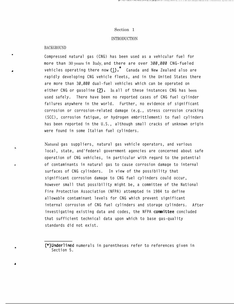
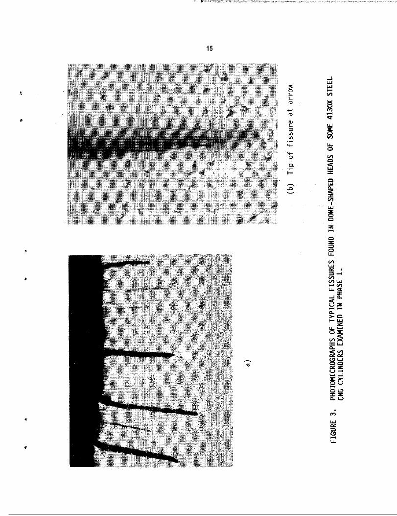
Several of the steel cylinders contained deep, narrow, crack-like,
fissures near vaive openings in the hemispherically shaped, formed
ends of cylinders. Photomicrographs of typical fissures are shown in
Figure 3. Wall thicknesses at these locations were considerably
greater than typical thicknesses in the walls of cylinder bodies. The
fissures were blunt and filled with oxide. Also, progressive internal
oxidation and decarburization was evident along the sides of fissures.
These features are evidence that the fissures were developed at an
elevated temperature and, therefore, they are related to the
manufacturing operation and not to service. It is believed that the
fissures are folds produced during cylinder closure operations. There
was no evidence of crack propagation from the ends of the folds.
Liquid residues found in three of the steel cylinders consisted of
water, solvent, and hydrocarbons, predominantly oils from compressors
used to fill the cylinders.

19
FINDINGS OF THE PHASE I PROGRAM
The most
below.
.
.
.
il
.ir
.
.
I .
.
significant findings of the Phase I program are summarized
The principal corrosive contaminants in U.S. natural gasesare C02, H2S, other sulfur species, oxygen, and water.
Natural gas transmission and distribution companies in theU.S. do not routinely analyze their products for H2S, othersulfur species, and water. Results of general corrosiontests showed that water is the key contaminant, since noneof the other contaminants produced significant corrosion ofcylinder materials in the absence of ljquid water.
Available analyses of U.S. natural gases from transmissionpipelines and distribution systems indicate that corrosivecontaminants in natural gases generally are well withinlimits set by transmission companies for natural gasesentering transmission pipelines and by the U.S. Departmentof Transportation for natural gases to be used in CNGservice. An exception was water vapor which was very highin some distribution lines.
Both 4130X and 15830 steels were susceptible to SCC inliquid water environments saturated with H2S.
The 15B30 steel was more susceptible to general corrosionthan was the 4130X steel, i.e., in corrosive environmentsthe general corrosion rates of the 15B30 steel were greaterthan the general corrosion rates of the 4130X steel.
None of the CNG cylinder alloys was susceptible to SCC inenvironments containing a typical pipeline gas or threeuntreated natural gases from wells in New York State.
Aluminum alloy 6061-T6 was not susceptible to SCC or generalcorrosion in any environment tested, including H2S-containing environments which induced severe cracking in the4130X and 15830 steels.
No environmentally induced cracking or significant corrosiondamage of any kind was found in extensive visual,ultrasonic, magnetic particle, spectrographic, andmetallographic analyses of nine CNG cylinders which had beenin CNG service for periods ranging from two to thirteenyears. These cylinders included eight 4130X steel cylindersmade by three U.S. manufacturers and one Italian

20
manufacturer, and one hoop-wrapped, fiber-reinforcedaluminum alloy 6061-T6 cylinder made in the U.S. The eightsteel cylinders were of various sizes and wall thicknesses,and the hardnesses of the 4130X steels used varied from HRB96 to HRC 32. These hardness levels correspond to avariation in ultimate tensile strength from a minimum ofabout 103 ksi to a maximum of about 144 ksi.
The most significant finding of the work performed in the Phase I
program was the condition of the nine used CNG cylinders. Analyses
indicated that the cylinders had been exposed to corrosive
environments, and several of the cylinders contained manufacturing
defects of sufficient size to act as crack starters. However, no
evidence of environmentally induced crack growth or crack initiation
and only minor general corrosion and pitting were found in the
cylinders. No environmentally induced damage of any kind was found in
the examination of the aluminum cylinder. These results, while
limited to nine CNG cylinders, suggest that significant internal
corrosion damage to CNG cylinders containing typical U.S. natural
gases is not likely.
The observed immunity of aluminum al
in H2S-containing environments which
l-T6 to corrosion and SCCloy 606
caused SCC and corrosion of the
steels and the excellent condition of the used aluminum CNG cylinder
also are significant. These results indicate that 6061-T6 aluminum
CNG cylinders may be expected to provide superior corrosion resistance
in high-H2S environments that are capable of inducing SCC and
significant general corrosion in steels.
4
, -. z. s.. ,. >. ..~. , . ,. _. .” )/ .’ -..’
21
Section 3
PHASE II PROGRAM
OBJECTIVES
The results of the Phase I program established: (1) the immunity of
aluminum alloy 6061-T6 in typical and highly-contaminated natural
gases; (2) that typical steels used in CNG cylinders (4130X and 15B30)
were not susceptible to SCC or to significant corrosion damage in
environments containing four typical natural gases; and (3) that the
primary contaminants in natural gases that are corrosive to steels
used in CNG cylinders are H2S and other sulfur compounds, C02, water
vapor, and oxygen. The thrust of the Phase II program was toaccomplish the remaining objectives of the overall program:
-n
. to define the concentration limits for corrosivecontaminants in natural gases that are necessary to insurethat internal corrosion of steel CNG cylinders does not
constitute a hazard to the structural integrity of cylindersover their lifetimes, and recornnend a gas-quality standard;and
. to define the effects of materials variables such asstrength (hardness) and microstructure on corrosion and SCCsusceptibility of steels used in CNG cylinders.
These objectives were accomplished through the conduct of additional
corrosion and SCC tests and analysis of the overall program results.
The experimental program conducted in Phase II and the results
obtained are presented and discussed below. Recommendations based on
the results of the overall program and a gas-quality standard
developed from analysis of the results are presented in Section 4.

CORROSION TEST PROGRAM
Background
22
The technical literature reviewed in Phase I, and, to some extent, the
results of the Phase I test program, indicated that H2S is the natural
gas contaminant of most concern with respect to the structural
integrity of steel CNG cylinders because of the ability of H2S to
induce sulfide stress corrosion cracking (SSC) in carbon and low-alloy
steels. The problem of selecting metallic materials for the
containment and handling of H2S-containing gases has been dealt with
by the National Association of Corrosion Engineers (NACE). NACE
Standard MR-01-75, "Sulfide Stress Cracking Resistant Material for Oil
Field Equipment," (2) details limitations on gas quality and
mechanical properties of metals necessary to prevent failure of metals
by SSC. (It should be noted that MR-01-75 does not apply to other
forms of corrosion damage ; it is applicable only to SSC). Paragraph
1.3 of MR-01-75 indicates the parameters governing SSC resistance are
as follows:
Fluids containing water as a liquid and hydrogensulfide are considered sour environments and may causeSSC of susceptible materials. This phenomenon isaffected by complex interactions,of parametersincluding: (1) metal chemical composition, strength,heat treatment, and microstructure; (2) pH; (3)hydrogen sulfide concentration and total pressure; (4)total tensile stress; (5) temperature; and (6) time.
For sour gas environments, MR-01-75 requires that:
Materials shall be selected to be resistant to SSC orthe environment should be controlled if the gas beinghandled is at a total pressure of 65 psia or greaterand if the partial pressure of H2S in the gas isgreater than 0.05 psia.
In the case of steels and other ferrous materials, MR-01-75-states:

23
Most ferrous metals, hardenable by heat treatmentand/or cold work can be made susceptible to SSC.Conversely, many ferrous metals may be heat treated toprovide acceptable resistance to SSC.
In general, carbon and low-alloy steels are acceptable under MR-01-75
at a maximum hardness of HRC 22 in all normal heat-treatment
conditions (as rolled, annealed, normalized, normalized and tempered,
and quenched and tempered), provided they contain less than one
percent nickel. Restrictions may be more rigorous or less rigorous
for specific steels. For example, CrMo steels, of which 4130X is one,
are acceptable under MR-01-75 at a maximum hardness of HRC 26, if they
are in the quenched-and-tempered heat treatment condition.
MR-01-75 also deals with other materials than steels. Importantly
I with regard to CNG cylinders, all aluminum-base alloys are acceptable
for use in sour gas environments.
- However, it should be noted that MR-01-75 covers all steels, and as a
result of this "universal applicability" approach, MR-01-75 may be too
restrictive for specific steels. Higher H2S partial pressures, higher
hardnesses, or both may be acceptable for specific steels and
environments. Recent work has shown that CrMo oil-field steels are
not susceptible to SSC in sour environments at hardness levels between
HRC 25 and 29 for H2S partial pressures ranging from 0.15 to 1.5 psia,
with the exact acceptable H2S limit for a given steel depending upon
steel composition, heat treatment, and hardness (10).-
T e s t M a t e r i a l s , C o n d i t i o n s , a n d P r o c e d u r e s
Both MR-01-75 and the Phase I program results indicated that aluminum
alloy 6061-T6 is immune to corrosive attack in natural gas
environments, including aqueous environments highly contaminated with
H2S. The major portion of the Phase II test program therefore was

24
directed toward defining acceptable H2S and hardness limits for 4130X
and 15830 steels, the materials which have been most widely used in
the manufacture of CNG cylinders. Further, since Phase I test results
showed that these steels were not susceptible to significant corrosion
or SCC in the absence of liquid water, all tests in Phase II were
conducted in liquid water. Five H2S partial pressures--0.05, 0.15,
0.50, 1.50, and 5.00 psia--were used in the test program. These
pressures were selected to range from the maximum H2S partial pressure
allowed under MR-01-75 without hardness control to an H2S partial
pressure greater than the largest partial pressure used in the
experimental study mentioned previously (10). The complete range of-H2S partial pressures was studied for the more widely used 4130X
steel. Tests on the less common 15B30 steel were limited to H2S
partial pressures of 0.05, 0.50, and 5.00 psia.
All tests were conducted at a total pressure of 3,000 psig, with the
balance of the pressure supplied by high-purity methane. Specimens in
all tests were submerged in deaerated, deionized water which was
saturated with the gases of interest. Baseline tests in water
saturated with high-purity methane also were conducted. Test
equipment and procedures were the same as in the Phase I test program,
with the exception of the procedure followed to establish H2S partial
pressures. The autoclaves containing test specimens were flushed with
argon and deaerated, deionized water was then introduced. The
autoclave was alternately flushed with argon and then evacuated
several times to remove any remaining air. Hydrogen sulfide was then
slowly bubbled through the aqueous phase until the required partial
pressure was established in the gas phase above the water. A
manometer system accurate to 0.01 psia was used to measure partial
pressures less than one atmosphere.
The hardness levels investigated were selected to be representative of
CNG cylinders used in the U.'S. and other countries. Three hardness
levels--HRC 21/22, HRC 25/26, and HRC 29/30--were used. Information

25
P
obtained in Phase I indicated that CNG cylinders used in Italy and
Canada can have hardnesses as high as HRC 32 and HRC 26, respectively;
the two higher hardness values were selected to be representative of
steel conditions in CNG cylinders used in these countries. There
currently are no hardness limits for CNG cylinders used in the U.S.
Cylinders examined in Phase I which had been used in the U.S. ranged
in hardness from HRB 96 to HRC 25. However, the MR-01-75 criteria for
handling H2S-containing gases are widely accepted and have been
incorporated into or referenced in laws in several states. Therefore,
it was considered important to evaluate the applicability of the HRC
22 hardness limit to CNG cylinders, and HRC 22 was selected as the
third hardness value used in the Phase II test program.
4
0
Test specimens were made from the same steel plates used in the Phase
I program. The compositions of the two steels are given in Table 1.
The majority of steel cylinders in CNG service in the U.S. are in the
quenched-and-tempered heat treatment condition, although 49 CFR 178.37
also allows the use of normalized cylinders. Correspondingly, the .
Phase II program was designed to compare corrosion and SCC
susceptibility of steels in the quenched-and-tempered and normalized
conditions. The plates were quenched and tempered at Southwest
Research Institute to produce the three desired hardnesses using heat
treatment procedures which were developed experimentally. The heat
treatment conditions used to produce the three hardness levels for the
4130X and 15B30 steels are given in Table 2.
The technical literature examined in Phase I suggested that after H2S,
CO2 was the natural gas contaminant with the greatest potential for
significant internal corrosion damage to CNG cylinders. Gas company
gas-quality standards and DOT Specification E 8009 for CNG both allow
a maximum of 3 volume percent C02. Therefore, the CO2 partial
pressure in a CNG cylinder operated at a total pressure of 3,000 psi
could be as high as 90 psia and still be within the CO2 limits of the
existing specifications. However, oil-and-gas industry experience

TABLE 1
CHEMICAL CW’OSITIONS OF TEST MATERIALS
Elemental Composition (Weight Percent)Alloy or Specification C Mn P S Si Cr MO B- - - Fe Cu _Ils_ Zn Ti Al---p--p - - -
DOT 3AA -- 4130X Steel 0.25- 0.40- 0.04 0.05 0.15- 0.80- 0.15- -- Bal, -- _- -- -- --Specification 0.35 0.90 max max 0.35 1.10 0.25
4130X Test Steel(a) ' 0.33 0.54 0.007 0.019 0.23 1.07 0.19 - - Bal. -_ __ -_ _- - -
DOT 3AA -- Carbon-Boron Steel
15630 Test Steel(a)
0.27- 0.80- 0.035 0.045 0.3 -- -- 0.0005- Bal. -- -- -- -- --0.37 1.40 max max max 0.003
0.32 1.18 0.012 0.008 0.17 '-- -- 0.0022 Bal, -_ __ -- -- --
DOT 3AL -- 6061 Alloy -- 0.15 -- -- 0.40- 0.04- -- -- 0.7 0.15- 0.8- 0.25 0.15 Bal.,Specification max 0.8 0.35 max 0.40 1.2 max max
6061-~6 Test Alloy -- 0.12 -- -- 0.71 0.18 -- 0.0001 0.40 0.29 0.96 0.11 0.020 Bal.
(a) Obtained in the form of l/2-in. thick plate from Pressed Steel Tank Company, Milwaukee, Wisconsin.(b) Obtained in the form of 1/2-in. thick plate from Metal Samples, Inc., Munford, Alabama.
f ,c

R

28
indicates that if liquid water is present, CO2 partial pressures
greater than 7 psia can cause significant corrosion of steels, and
that significant corrosion damage is probable for CO2 partial
pressures greater than about 15 psia (8). These findings suggested
that current CO2 partial pressure limits for natural gas may be too
high for CNG if liquid water can be formed within the cylinders. The
effects of CO2 on quenched-and-tempered 15B30 and 4130X steels were
studied at CO2 partial pressures of 7, 30, and 90 psia. These values
are the oil-and-gas industry "rule of thumb," and the CO2 concentra-
tions corresponding to 1 percent CO2 and 3 percent CO2 in a CNG
cylinder at a total pressure of 3,000 psig. Tests also were conducted
in environments containing both H2S and CO2 in the gas phase. The
purpose of these tests was to determine if the two contaminants
together produced more severe corrosion damage than when only H2S or
only CO2 was present.
As-received (normalized) 4130X specimens, with a hardness of HRC
21/22, and quenched-and-tempered specimens of the same hardness were
tested to evaluate the effects of the different heat treatments
separately from the effects of hardness.
Two types of corrosion tests were conducted: SCC and general
corrosion. The same equipment and procedures used in Phase I (see
Section 2) were used in the Phase II SCC tests. Duplicate tensile
specimens for each alloy-heat treatment condition evaluated were
used. Normalized (as-received) 4140X steel at a hardness of HRC
21/22, and quenched-and tempered specimens at hardnesses of HRC 25/26
and HRC 29/30, were exposed in 11 tests. The HRC 21/22 normalized
specimens were used to evaluate the effects of heat treatments.
Samples of the 4130X steel at a hardness of HRC 22 in quenched-and-
tempered and in normalized heat-treatment conditions were exposed in
two tests to separate effects of hardness and heat treatment.
Quenched-and-tempered specimens of 15830 steel at the three hardness
levels were exposed in seven tests.

29
b"
s
A slow strain rate of 2 x 10B7 set-' was used in all SCC tests, as in
Phase I. However, Phase II SCC tests were conducted at a temperatureof 77°F (25"C), rather than the 140°F test temperature used in Phase
I, because most steels display maximum susceptibility to H2S-induced
stress cracking near this temperature.
General corrosion test specimens consisted of coupons with nominal
dimensions of 1 inch x 1 inch x l/8 inch. Duplicate specimens of each
steel were exposed for each heat-treatment condition. Corrosion rates
were determined from weight-change measurements, and selected
specimens were examined metallographically. General corrosion tests
in the Phase II program were limited to C02-containing solutions.Tests-durations of 1,000 hours were used.
56
P
Tests were conducted at CO2 partial pressures of 30 psia and 90 psia
to simulate and evaluate the effects of 1 volume percent and 3 volume
percent CO2 in CNG. Tests were conducted on the 4130X steel in the
normalized (as-received) condition at a hardness of HRC 22 and in the
quenched-and-tempered condition at hardnesses of HRC 21/22, HRC 25/26,
and HRC 29/30 to define the effects of hardness and heat treatment on
general corrosion. Similarly, 15830 steel specimens were tested in
the as-rolled (as-received) condition at a hardness of HRB 84/87 and
in the quenched-and-tempered condition at hardnesses of HRC 21/22, HRC
25/26, and HRC 29/30.
S t r e s s C o r r o s i o n C r a c k i n g T e s t R e s u l t s
4 1 3 0 X S t e e l . Stress corrosion cracking test conditions and results
for the 4130X steel are given in Table 3. Test specimens with
hardnesses of HRC 25/26 and HRC 29/30 were in the quenched-and-
tempered heat treatment condition. Test specimens with hardnesses of
HRC 21/22 were in the normalized (as-received) condition, except in
Test No. 19. In Test No. 19, one HRC 21/22 specimen (Specimen B) was

TestHo.
I
7
3
4
5
6
8
EnviromentSpecimen
NoL
Water saturated withCH4 + 0.05 psia H2S
Water saturated withat4 + 0.15 psia H2S
Water saturated withCH4 + 0.50 psia H2S
Water saturated withCH4 + 1.50 psia H2S
Water saturated withCti4 + 5.00 psia H2S
Water + 0.5 psiaH2S(C)
TABLE 3
STRESS CORROSION CRACKING TEST RESULTS FOR 4130X STEEL(")
Material Condition
HRC = 21/22(d) HRC = 25/26(e1 HRC = 29/3O(e)
-L36 .O42.5-
Avg. 39.2
43.931.9
Avg. 37.9
43.737.8
Avg. 40.8
45.945.0-
Avg. 45.4
23.717.6
Avg. 20.6
0.42.4
Avg. 1.4
51.751.1-
Avg. 51.4
UTS Secondaryk u Cracking
UTS Secondaryk & m Cracking
11.1 NOtb)12.3 NO11.7
12.6 120.110.3 121.0Ii3 120.6
12.5 120.83120.312.4 120.6
12.9 125.417.6 123.015.2 124.2
10.2 NO8.3 NO9.2
1.4 107.13.4 121.0
-2x714.0
NoNo
YesYes
NoNo
YesYes
YesYes
YesYes
NoNo
(a)(b)
Total pressure is 3,000 psig unless otherwise noted.
(c)ND -- not determined due to equipment malfunction.Total pressure was 0.5 psia.
(d) As-received hardness, unless otherwise noted.(e) Austenitized, quenched, and tempered to indicated hardness at SwRI.
61.5 18.2 ND60.7 18.2 NO
Avg. m 18.2
63.7 18.8 121.9-.2- 64 2 18.2 124.9
Avg. 74.0 m 123.4
63.5 18.6 124.163.817.9122.7
Avg. 63.6 18.2 123.4
63.3 17.6 124.363.218.2124.0
Avg. 63.2 17.9 124.2
49.8 17.8 ND61.118.4 ND
Avg. 60.4 18.1
36.1 15.8 132.449.0 18.0 127.0
Avg. 42.6 16.9 129.7
61.2 17.9 127.564.2 18.8 123.7
Avg. 62.7 18.4 m
NoNo
NoNo
NoNo
NoNo
YesNo
YesYes
NoNo
62.256.4 17.0 Ii:17 0Avg.
-...-L-59.3 17.0
60.2 18.0 133.656.0
Avg._-58.1
17 9 142.2--L18.0 137.9
61.1 17.2 140.1
Avg.$0.360.9
16-9 141.617.0 140.8
60.4 16.4 143.6
Avg.62.261.3-- 18.1 137.017.2 140.3
58.855.9 17.0 ix16.2Avg.-57.4 16.6
21.5 9.6 140.014.7__ 9.0 136.6
Avg. 18.1 9.3 138.4
61.0 17.3 140.9
Avg.61.3 17.4 137.461.2 17.4 139.2
SecondaryCracking
NoNo
NoNo
NoNo
NoNo
YesYes
YesYes
NoNo
b

181 FB
Test SpecimenNo. Enviroment _ tb.
7 Water saturated withCH4 + 90 psia CO2 :i
9 Water saturated withCH4 + 30 psia CO2 :i
10 Water saturated withCH4 + 7 psia CO2 :i
19 Water saturated with
+4CH + 0.05 psia H2S i
psia CO2
TABLE 3
STRESS CORROSION CRACKING TEST RESULTS FOR 4130X STEEL(*)(Continued)
Material Condition_ .HRC = 25/26te)
UTS Secondary&- k (ksi) Crackinq
HRC = 21/22(d)
UTS Secondary& (ksi) Cracking'2"x)
28.2 12.2 123.3 No19.8 -123.6 No
Avg. 24.0 10.6 123.4
23.7 11.2 125.2 No28.2 12.0 125.3 No
Avg. 26.0 11.6 125.2
29.9 10.1 120.4 Yes25.2 8.1121.0 Yes
Avg. 27.6 9.1 120.7
24.0 No62.9te) ii:; :;::: No
HRC = 29/30(e)
RA EL UTS Secondary&& I%1 (ksi) Cracking
62.6 18.4 122.9 No 55.1 16.4 140.4 No$3.03.0121.8 No No
Avg. 62.8 18.6 122.4 Avg. 60.817.5136.4 58.0 17.0 138.4
62.5 18.4 122.7 No 60.2 18.0 138.4 No64.0 18.7 124.6 No
18.6 123.6mG138.1 No
Avg. 63.2 Avg. 60.6 17.7 138.2
64.2 18.2 125.0 No 62.2 19.0 135.7 No$!L4!L4fi No No
Avg. 64.8 18.9 122.8 Avg.58.5 17.1 141.5-60.9 18.0 138.6
55.9 16.6 118.4 No 55.4 17.4 131.3 Yes60.8 17.4 118.4 No 55.416.0131.8 Yes
Avg. 58.4 17.0 118.4 Avg. 55.4 16.7 131.6
(a) Total pressure is 3,000 psig unless otherwise noted.(b) ND -- not determined due to equipment malfunction.(c) Total pressure was 0.5 psia.(d) As-received hardness, unless otherwise noted.(e) Austenitized, quenched, and tempered to indicated hardness at SwRI.

32
tested in the quenched-and-tempered condition to provide a direct
comparison with the normalized specimen (Specimen A) used in the same
test. Results of additional tests to compare susceptibilities of
normalized and quenched-and-tempered 4130X specimens are given in
Table 4.
Figure 4 is a graphical presentation of results from SCC tests on
4130X steel specimens in H2S-containing environments. Figure 5 is a
similar presentation of results from tests on 4130X steel specimens in
CO*-containing environments. Percent-reduction-in-area values are
plotted versus H2S and CO2 partial pressures, respectively.
B a s e l i n e T e s t . Baseline data for 4130X steel specimens were
obtained in water saturated with pure methane (Test No. 1). The
normalized HRC 21/22 steel specimens were inherently more brittle than
the higher-hardness, quenched-and-tempered 4130X specimens. The
ductility parameters of the normalized HRC 2-l/22 specimens were about
30 percent less than those of the quenched-and-tempered HRC 25/26 and
HRC 29/30 specimens.
t$S E f f e c t s . H2S was the oniy gaseous contaminant in Test Nos. 2
through 6 and Test No. 8. The normalized HRC 21/22 material was
susceptible to cracking at H2S partial pressures of 0.50 psia or
higher and at 0.05 psia. It is not clear why the normalized specimens
did not crack at the intermediate pressure of 0.15 psia H2S. However,
this was not the only ambiguity in results from the normalized
material. Test No. 8, a repetition of Test No. 4 in which both
specimens cracked, did not produce cracking, and both normalized
specimens had good ductility in Test No. 8.
Results from the HRC 25/26 and HRC 29/30 specimens were more
uniform. One of the HRC 25/26 specimens was not susceptible to
cracking at an H2S partial pressure of 1.50 psia, while the second
specimen was susceptible (Test No. 5); both of the HRC 29/30 specimens
c

* 0
TABLE 4
STRESS CORROSION CRACKING TESTS ON 4130X STEEL IN DIFFERENT HEAT-TREATMENT CONDITIONS
As Received Quenched and Tempered(HRC/21/22) (HRC 21/22)
lest No. Environment (:; $T,(z;SecondaryCracking 2 &(g
17 Water saturated with CHa 33.4 11.2 113.0 Yes 63.3 20.1 103.8 No+ 1.50 psia H2S 25.7 112.8 Yes- - 61.6 19.4 103.8 No E__ _I_
Avg. 29.619o:f:
112.9 Avg. 62.4 19.8 103.8
18 Water saturated with CH4 28.9 11.9 119.9 No 52.3 20.2 110.8 No+ 7 psia CO2 25.0 10.0 119.6 No 61.4 18.5 112.8 No
119.8- -
Avg. 27.0 11.0 Avg. 56.8 19.4 111.8

34
da
60
40
30
20
!I/22 NORMQ HRC 21122 Q & TA HRC 25/26 Q & T
IOHRC 29/30 Q & T
H,S PARTIAL PRESSURE (PSIA)
FIGURE 4, SUMMARY OF STRESS CORROSION CRACKING TEST RESULTS FOR
4130X STEEL EXPOSED IN H2S-CONTAINING SOLUTIONS. Solid
points indicate cracking; open points indicate no
cracking.

.F
Y
60 ’--I--
35
t+o.o5 PSI H2.S)
t+o.o5 PSI H2S)
ElI
(+0.05 PSI H2S)4130X STEEL
El HRC 21/22 NORMQ HRC 21/22 Q & TA HRC 25126 Q & T0 HRC 29/30 Q & T
I
CO2 P A R T I A L P R E S S U R E (PSIA)
FIGURE 5. SUMbfARY OF STRESS CORROSION CRACKING TEST RESULTS FOR
4130X STEEL EXPOSED IN COz-CONTAINING SOLUTIONS. Solid
points indicate cracking; open points indicate no
cracking.
36
were susceptible at this pressure. All of the HRC 25/26 and HRC 29/30
specimens were susceptible to cracking at H2S partial pressures of
5.00 psia. While the 4130X steel was susceptible to cracking in all
three heat treatment conditions at an H2S partial pressure of 5.00
psia, the normalized HRC 21/22 specimens were significantly more
brittle (i.e., ductility parameters were smaller) than any of the
quenched-and-tempered specimens. In general, at the same H2S partial
pressures the HRC 29/30 specimens were embrittled more than the HRC
25/26 specimens.
Test No. 17 (Table 4) was conducted to compare the behavior of
normalized and quenched-and-tempered specimens at the same hardness
under conditions previously shown to cause cracking and embrittlement
of the normalized material. The hardness of all the specimens was HRC
21/22. An H2S partial pressure of 1.50 psia was used. Both
normalized specimens cracked and were severely embrittled. The
quenched-and-tempered specimens were not susceptible to cracking or to
embrittlement.
C& E f f e c t s . Test Nos. 7, 9, and 10 (Table 3) were conducted in
water saturated with 90, 30, and 7 psia of C02, respectively. None of
the quenched-and-tempered HRC 25/26 and HRC 29/30 specimens were
susceptible to cracking or to embrittlement in any of the tests
containing C02. The normalized HRC 21/22 specimens were not
susceptible to cracking at CO2 partial pressures of 90 and 30 psia
(Test Nos. 7 and 9), although all of the normalized specimens exposed
in these two tests suffered some embrittlement. Both normalized
specimens were susceptible to cracking and embrittlement in Test No.
10 at a CO2 partial pressure of 7 psia.
Test No. 18 (Table 4) was conducted to compare the behavior of
normalized and quenched-and-tempered specimens at the same hardness.
The hardness used was HRC 21/22, and the CO2 partial pressure used was
7 psia. Unlike Test No. 10 in which the normalized specimens cracked
/,.~“,,.^ ..,.. ,.,_ ,.,. _ _,., .,~ ,..,, j
37
at a CO2 partial pressure of 7 psia, neither normalized specimen
cracked in Test No. 18, although both specimens displayed some loss of
ductility. Neither of the quenched-and-tempered specimens was
susceptible to cracking, and both displayed good ductility.
Combined H2S and CO2 Effects. A single test (Test No. 19, Table
3) was conducted with 0.05 psia H2S and 7 psia CO2 present in the gas
phase. One quenched-and-tempered HRC 21/22 specimen and one
normalized HRC 21/22 specimen were exposed. All of the HRC 25/26 and
HRC 29/30 specimens were in the quenched-and-tempered condition.
Neither of the HRC 21/22 specimens developed cracks. However, the
normalized specimen (Specimen A) was severely embrittled. The
ductility parameters of the quenched-and-tempered HRC 21/22 specimen
were similar to those of the quenched-and-tempered HRC 21/22 specimens
in Test No. 18 (Table 4). Neither of the quenched-and-tempered HRC
25/26 specimens was susceptible to cracking in the combined H2S-CO2
environment, but both displayed lower ductility values than in the
test with 0.05 psia H2S only (Test No. 2) or in the test with 7 psia
CO2 only (Test No. 10). Both quenched-and-tempered HRC 29/30
specimens were susceptible to cracking in the combined H2S-CO2
environment, whereas specimens of this hardness were not susceptible
in the pure H2S environment (Test No. 2) or in the test with 7 psia
CO2 only (Test No. 10).
The results of Test No. 19 show that the combined H2S-CO2 environment
was more severe than environments containing only H2S at a partial
pressure of 0.05 psia or only CO2 at a partial pressure of 7 psia. It
is believed that the embrittlement and cracking of 4130X steel
specimens in the combined environment were caused by hydrogen. The pH
of the combined H2S-CO2 environment was not measured, but it would
have been/lower than either the H2S environment in Test No. 2 or the
CO2 environment in Test No. 10. As a result, in the combined H2S-CO2
environment more hydrogen ions would have been available to be reduced
to hydrogen atoms, and the amount of atomic hydrogen available to

38
enter the steels and cause hydrogen embrittlement and cracking would
have been correspondingly greater. A hydrogen mechanism is consistent
with the fact that cracking occurred in the highest strength (highest
hardness) specimens, since susceptibility of steels to hydrogen-
induced cracking increases as the yield strength of a steel is
increased.
15B30 S t e e l . Results of stress corrosion cracking tests conducted on
15B30 steel specimens are tabulated in Table 5 and are shown
graphically in Figure 6 for H2S-containing environments, and in Figure
7 for C02-containing environments. All 15B30 specimens tested were in
the quenched-and-tempered condition. As with the 4130X steel,
specimens of the 15830 steel were tested at hardnesses of HRC 21/22,
HRC 25/26, and HRC 29/30.
t-i@ E f f e c t s . Test Nos. 11, 12, and 13 (Table 5) were conducted
in water saturated with H2S at partial pressures of 0.05 psia, 0.15
psia, and 5.00 psia, respectively. No specimens were susceptible to
cracking at H2S partial pressures of 0.05 psia and 0.15 psia. One
specimen at each of the three hardness levels cracked in Test No. 13
at an H2S partial pressure of 5.00 psia. Ductility parameters were
not significantly affected at pressures of 0.05 and 0.15 psia H2S, but
all of the specimens tested at 5.00 psia H2S were severely embrittled.
Embrittlement was hardness dependent, i.e., the HRC 29/30 specimens
were more severely embrittled than the HRC 25/26 specimens, which were
more severely embrittled than the HRC 21/22 specimens.
in water saturated
CO2 E f f e c t s . Test Nos. 14, 15, and 16 (Table 5) were conducted
with 90, 30, and 7 psia of C02, respectively. None
of the 15830 specimens was susceptible to cracking in any of the three
tests. The ductilities of the HRC 25/26 and HRC 29/30 specimens at
CO2 partial pressures of 90 and 30 psia (Test Nos. 14 and 15) were
substantially reduced. The HRC 29/30 specimens also were embrittled
in the test at a CO2 partial pressure of 7 psia (Test No. 16), but the
?

Q
TestHO.
11
17
II
14
15
16
20
TABLE 5
STRESS CORROSION CRACKING TEST RESULTS FOR 15830 STEELla)
HRC = Zl/Z2(d)
Nateriai Condition
HRC = 25/26td) HRC = 29/30td)
SpecimenEnviroment NoA
Water saturated withCH4 + 90 psia CO2 ;
Water saturated withCH4 + 30 psia CO2 1:
Water saturated withCH4 + 7 psia CO2 ::
Water saturated with 13CH4 + 0.05 psia H2S.+ 147 psia CO2
UTS Secondaryb fksi) Cracking
UTS Secondary$1 & (ksi) Cracking
59.6 19.1 109.556.4 18.3 110.7
Avg. 58.0 ifi7 101.0
57.556.9
Avg. 57.2
18.6 110.819 0 111.4218.8 m
14.313.9
Avq. 14.1
10.1 113.79.3 -113.09.7 113.4
56.3 17.8 79.856 1-.-L 18.0 79.4
Avg. 46.2 17.9 79.6
56.0 18.6 NI(‘)55.1 18.3 ND
Avg. 55.6 18.4
59.056.8
Avg. 57.9
18.6 110.218.2 111.6-18.4 110.9
61.2 18.7 108.360.9 19.0 108.7
Avg. 61.0 18.8108.5
NoNo
NoNo
NoYes
NoNo
NoNo
NoNo
NoNo
56.3 18.2 120.253.6 16.9 121.1
Avg. 55.0 17.6 120.6
55.6 17.2 120.455.417.6121.6
Avg. 55.5 17.4 121.0
7.9 2.8 114.9
Avg. 9.6 4.1 117.6
46.1 17.8 80.853.6 16.9 79.4
Avg. 49.8 17.4 80.1
53.0 17.2 ND47.4 - 23.7 NO
Avg. 50.2 20.4
55.3 19.1 120.453.616.4120.0
Avg. 54.4 17.8 120.2
53.3 16.1 112.554.5 16.8 112.1
Avg. 53.9 16.4 712.3
NoNo
NoNo
Yes
NoNo
NoNo
NoNo
NoNo
57.5 16.4 136.5----L 56.0 16 0
Avg. 56.8 16.2138.4137.4
48.8 14.5 137.955.5 16.2
Avg. 52.2 15.4llL,l137.8
Avg.--::;
35.4 12.2 82.029.4 10.2
Avg. 32.4 11.279,j80.6
41.6 5.0-----2 28.1 9 2 ix
Avg. 34.8 7.1
Avg.
41.0 12.9 37.031.1 11 5 136.0s-.--L-36.0 12.2 136.5
43.0 14.2 131.1 No
Avg.50.215.0128.946.6 14.6 130.0
NoNo
NoYes
NoNo
NoNo
NoNo
(a)(b)
Total is 3,000 psig unless otherwise indicated.
(c)Total pressure is the H2S pressure
(d)ND -- not determined due to equipment malfunction.Austenitized, quenched, and tempered to indicated hardness at SwRI.

40
6060
50
40
30
20
10
0
2015830 STEEL15830 STEEL
00 HRC 21/22 QHRC 21/22 Q && TTA HRC 25/26 Q & TA HRC 25/26 Q & T 4)4)00 HRC 29/30 QHRC 29/30 Q ACAC TT
10
000 a 0.05a 0.05 0.150.15 0.500.50 1.501.50 5.005.00
H,S PARTIAL PRESSURE (PSIAIH,S PARTIAL PRESSURE (PSIAI
FIGURE 6, SUMMARY OF STRESS CORROSION CRACKING TEST RESULTS FOR 15830
STEEL EXPOSED IN H2S-CONTAINING SOLUTIONS. Solid points
indicate cracking; open points indicate np cracking.

41
60.
K 50.Y
d
2
z 40-
10-
O-
A(+0.05 PSI H,SI
(+0.05 PSI HpS)
15830 STEELHRC 21122 Q & T
A HRC 25/26 Q & TA HRC 25/26 Q & T00 HRC 29130 Q & THRC 29130 Q & T
I II
II I I
00 77 3030 9090
CO, PARTIAL PRESSURE (PSIA)
FIGURE 7. SUMMARY OF STRESS CORROSION CRACKING TEST RESULTS FOR 15B30
STEEL EXPOSED IN CO*-CONTAINING SOLUTIONS. Solid points
indicate cracking; open points indicate no cracking.

42
ductility parameters of the HRC 25/26 specimens were not affected.
HRC 21/22 specimens were not subject to embrittlement in any of the
C02-containing environments.
C o m b i n e d H2S a n d CO2 E f f e c t s . A single test (Test No. 20, Table
5) was conducted with 0.05 psia H2S and 7 psia CO2 present in the gas
phase. The 15B30 steel was not susceptible to cracking at any of the
three hardness levels. The HRC 29/30 specimens suffered some loss in
ductility. The degree of embrittlement was greater than when the
environment contained only H2S at a partial pressure of 0.05 psia
(Test No. 11) and was less than when the environment contained only
CO2 at a partial pressure of 7 psia (Test No. 16). Results for'the
HRC 25/26 and HRC 21/22 specimens in the combined H2S-CO2 environment
were not significantly different than when only H2S or only CO2 were
present. *\
G e n e r a l C o r r o s i o n T e s t s
Two general corrosion test exposures were conducted to determine
corrosion rates of 4130X and 15B30 steels in CO21containing
solutions. Coupons were exposed for 1,000 hours at 77°F (25°C).
Duplicate specimens of as-received (normalized) 4130X steel, duplicate
specimens of as-received (as-rolled) 15B30 steel, and duplicate
specimens of both steels quenched and tempered to three hardness
levels (HRC 21/22, HRC 25/26, and HRC 29/30) were tested in each
environment. The environments in the two tests consisted of
deaerated, deionized water saturated with CO2 at partial pressures of
30 psi and 90 psi, respectively.
Test results from 4130X and 15830 steel coupons are given in Tables 6
and 7, respectively. The presence and severity of pitting corrosion
also are indicated in the tables. "Minor" pitting indicates the
presence of shallow pits that were less than about O.OOE-inch deep,
corresponding to a pitting rate of less than about 0.020 in./yr

TABLE 6
l,OOO-HR CORROSION TESTS ON 4130X STEEL IN C02-SATURATED WATER
H e a t T r e a t m e n tC o n d i t i o n
Normalized
Quenched & Tempered
Quenched & Tempered
Quenched & Tempered
Hardness
HRC 21/22
Avg.
HRC 21/22
Avg.
HRC 25126
Avg.
HRC 29/30
Avg.
C o r r o s i o n R a t e (milslyear)
iNotes)*30 psiCO2 P r e s s u r e
9 0 p s i ( N o t e s ) *
15.5 A12.6 A14.0 Avg.
4.8 B5.9 A5.4 Avg.
5.7 A6.8 A6.2 Avg.
6.3
k9"
CB
Avg.
30.429.730.0
7 . 9
it;
8.1
8.39.18.7
AA
AB
AA
BC
*Notes: A -- no pitting; B -- minor pitting; C -- moderate pitting.

TABLE 7
l,OOO-HR CORROSION TESTS ON 15830 STEEL IN CO*-SATURATED WATER
H e a t T r e a t m e n tC o n d i t i o n
As Rolled
Quenched & Tempered
Quenched & Tempered
Quenched & Tempered
Hardness
HRB 84/87
Avg.
HRC 21/22
Avg.
HRC 25126
Avg.
HRC 29/30
Avg.
C o r r o s i o n R a t e (mils/year)
3 0 p s i ( N o t e s ) *CO2 P r e s s u r e
9 0 p s i ( N o t e s ) *
18.7 D 32.1 D20.2 D 33.2 A19.4 Avg. 32.6
13.8 : 24.3 A12.6 22.9 A13.2 Avg. 23.6
18.7 B 41.1 A17.7 B 38.5 A18.2 Avg. 39.8
17.2 C 40.0 A17.0 B 43.1 A17.1 Avg. 41.6
*Notes: A -- no pitting; B -- minor pitting; C -- moderate pitting.

45
(mrw). "Moderate" pitting indicates the presence of pits with depths
between about 0.002 and about 0.006 inch, corresponding to a pitting
rate of about 20 to 50 mpy. And, "severe" pitting indicates the
presence of pits deeper than about 0.006 inch, corresponding to a
$ pitting rate greater than 50 mpy.
4130X Steel. The results of the tests on the 4130X steel
indicate a significant dependence of general corrosion rate on the
heat treatment condition of the material. For both partial pressures
of co2, the general corrosion rates of the normalized HRC 21/22
specimens were about three times greater than the corrosion rates of
the quenched-and-tempered HRC 21/22 specimens and at least twice the
corrosion rates of any of the quenched-and-tempered HRC 25/26 and HRC
29/30 specimens. General corrosion rates of the quenched-and-tempered
specimens were independent of hardness in both test solutions. For
all heat treatment conditions, general corrosion rates were higher in
the go-psi CO2 solution than in the 30-psi CO2 solution. The 4130X
steel specimens suffered minor to moderate pitting, and pitting was
essentially independent of CO2 partial pressure and heat treatment
condition.
15B30 Steel. The 15830 steel (Table 7) was significantly more
susceptible than the 4130X steel to both general corrosion and
pitting. General corrosion rates of the 15B30 steel specimens in the
go-psi CO2 solution were approximately twice the rates obtained in the
30-psi CO2 solution. Within a single test solution, general corrosion
rates were independent of both heat treatment condition and hardness.
Pitting corrosion of the 15B30 steel in the 30-psi CO2 solution was
generally more severe than in the go-psi CO2 solution.
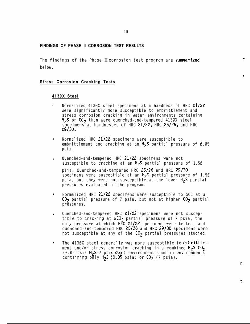
46
FINDINGS OF PHASE II CORROSION TEST RESULTS
The findings of the Phase II corrosion test program are summarized
below.
S t r e s s C o r r o s i o n C r a c k i n g T e s t s
4 1 3 0 X S t e e l
. Normalized 4130X steel specimens at a hardness of HRC 21/22were significantly more susceptible to embrittlement andstress corrosion cracking in water environments containingH2S or CO2 than were quenched-and-tempered 4130X steelspecimens at hardnesses of HRC 21/22, HRC 25/26, and HRC29/30.
. Normalized HRC 21/22 specimens were susceptible toembrittlement and cracking at an H2S partial pressure of 0.05psia.
l Quenched-and-tempered HRC 21/22 specimens were notsusceptible to cracking at an H2S partial pressure of 1.50
psia. Quenched-and-tempered HRC 25/26 and HRC 29/30specimens were susceptible at an H2S partial pressure of 1.50psia, but they were not susceptible at the lower H2S partialpressures evaluated in the program.
. Normalized HRC 21/22 specimens were susceptible to SCC at aCO2 partial pressure of 7 psia, but not at higher CO2 partialpressures.
l Quenched-and-tempered HRC 21/22 specimens were not suscep-tible to cracking at a CO2 partial pressure of 7 psia, theonly pressure at which HRC 21/22 specimens were tested, andquenched-and-tempered HRC 25/26 and HRC 29/30 specimens werenot susceptible at any of the CO2 partial pressures studied.
. The 4130X steel generally was more susceptible to embrittle-ment and/or stress corrosion cracking in a combined H2S-CO2(0.05 psia H2S-7 psia CO ) environment than in environmentscontaining only H2S (O.O$ psia) or CO2 (7 psia).

15B30 S t e e l
47
l Quenched-and-tempered 15830 steel specimens at hardnesses ofHRC 21/22, HRC 25/26, and HRC 29/30 were not susceptible tostress corrosion cracking in H2S-containing solutions whenthe H2S partial pressure in the gas phase was 0.50 psia orless. 15830 specimens of all three hardnesses weresusceptible to cracking and embrittlement at an H2S partialpressure.of 5.00 psia.
l Quenched-and-tempered 15B30 steel specimens were notsusceptible to stress corrosion cracking in any of the CO2environments evaluated. HRC 21/22 and HRC 25/26 specimenswere not susceptible to embrittlement in any of the CO2environments, but the HRC 29/30 specimens were susceptible toembrittlement at all three CO2 partial pressures studied.
. The behavior of 15830 steel specimens exposed in an H2S-CO(0.05 psia H2S-7 psia C02) environment was similar to resu?tsobtained in an environment containing only CO2 (7 psia). TheHRC 29/30 specimens were moderately embrittled, but did notcrack. Lower-hardness specimens were not susceptible toembrittlement or cracking.
G e n e r a l C o r r o s i o n
3 .
.
.
.
c.
%
General corrosion rates of quenched-and-tempered 4130X steelswere low and were essentially independent of hardness inenvironments saturated with CO2 at partial pressures of 30psia and 90 psia. However, the susceptibility of thequenched-and-tempered 4130X steels to pitting generallyincreased with hardness.
Normalized 4130X steels displayed high general corrosionrates in environments saturated with CO2 at partial pressuresof 30 psia and 90 psia.
Quenched-and-tempered 15B30 steel specimens of all threehardness levels displayed high general corrosion rates inenvironments saturated with CO2 at partial pressures of 30psia and 90 psia.
15B30 steel was more susceptible to pitting in C02-containingsolutions than was the 4130X steel.

48
Section 4
CONCLUSIONS AND RECOMMENDATIONS
CONCLUSIONS
The primary conclusions of the overall program are as follows:
. The principal corrosive contaminants in natural gases in theU.S. are H2S and other sulfur-containing species, CO2,oxygen, and water.
. Aluminum alloy 6061-T6 is suitable for use in CNG cylinders,regardless of the natural gas composition. Aluminum alloy6061-T6 is immune,to stress corrosion cracking,embrittlement, and other forms of general and localizedcorrosion in natural gas environments, including H2S and CO2environments that are capable of inducing cracking, embrit-tlement, pitting, and general corrosion in steels.
. Corrosion of CNG cylinders made of steel may be prevented bymaintaining the water vapor concentration of CNG gas suppliesbelow the dew point for the anticipated range of temperaturesand pressures. Steels are not subject to significantcorrosion in natural gas environments, regardless of theconcentrations of other contaminants, unless liquid water ispresent.
. Normalized 4130X steels are not suitable for use in CNGcylinders unless the water vapor concentration of the supplygas is sufficiently low to prevent condensation of liquidwater. Normalized HRC 21/22 4130 steel specimens cracked inenvironments containing as little as 0.05 psia H2S or 7.0psia CO2.
l Quenched-and-tempered 4130X steels are suitable for use inCNG cylinders at hardnesses to HRC 25/26 for natural gassupplies in which the H2S partial pressure is 0.15 psia orless and the CO2 partial pressure does not exceed 7 psia. Inthe absence of C02, quenched-and-tempered 4130X steel at ahardness of HRC 29/30 is acceptable.
l Quenched-and-tempered 15B30 steels are suitable for use inCNG cylinders at hardnesses to HRC 29/30 for natural gassupplies in which the H S partial pressure is 0.50 psia orless and the CO2 partia? pressure does not exceed 7 psia.

49
The limitation of 7 psia CO2 for quenched-and-tempered 15B30 steels is
necessary to prevent general corrosion and pitting in these
materials. Higher levels of CO2 can be tolerated by quenched-and-
tempered 4130X steels without significant general corrosion or
pitting, but test results indicated a limit of 7 psia CO2 is
appropriate for these steels to minimize the possibility of stress
corrosion cracking.
The above conclusions indicate that stress corrosion cracking is
possible in steel CNG cylinders for certain combinations of steels,
heat treatment conditions, hardnesses, and gas compositions. Since
current DOT regulations allow normalized steels to be used in CNG
cylinders, one of the most significant findings of the program is that
normalized 4130 steels with hardnesses of HRC 21/22 can suffer stress
corrosion cracking at very low levels of H2S or CO2 if liquid water
also is present.
Several of the eight used 4130X steel cylinders that were examined in'
the program had hardnesses in excess of HRC 21/22 and microstructures
that were not fully quenched and tempered. The absence of significant
corrosion in these cylinders, particularly the absence of crack growth
from large fabrication flaws found in several of the cylinders,
suggests that CNG supplies currently being used in the U.S. have very
low levels of H2S and C02, or the typical water vapor concentration of
the gases used in the cylinders examined was very low. The gas
analyses reported in Phase I are consistent with this observation.
With the exception of water, which was very high in a few gases from
distribution lines, corrosive contaminants in the gases analyzed were
well within limits established by DOT for CNG supplies.

50
RECOtMENDATIONS
G a s - Q u a l i t y S t a n d a r d
The primary objective of this research program was to develop a CNG
gas-quality standard for corrosive contaminants in natural gases that
is sufficient to insure that internal corrosion does not constitute a
hazard over the lifetimes of the cylinders. A gas-quality standard
for CNG is recommended which accomplishes this objective without being
economically impractical. It is based upon the results of this
program, and it draws upon existing standards (in particular, NACE MR-
Ol-75), practices, and experience in the gas production and
transmission industries and upon data available in the technical
literature.
The recommended gas-quality standard incorporates three options,
depending upon the CNG cylinder material used and the manner in which
CNG suppliers choose to control gas compositions, as follows:
. Aluminum Cyl inders. No restrictions on the concentrations ofcorrosive contaminants in natural gas are required for CNGcylinders made of aluminum alloy 6061-T6.
. S t e e l C y l i n d e r s . When the dew point of the natural gasentering a steel CNG cylinder is below the lowest anticipatedcylinder temperature at the highest anticipated cylinderpressure, no limitations are required on the concentrationsof other corrosive contaminants in the gas; or
. S t e e l C y l i n d e r s . When the dew point of the natural gasentering a steel CNG cylinder is not below the lowestanticipated cylinder temperature at the highest anticipatedcylinder pressure, the gas-quality in the cylinder shallcomply with the following limitations on corrosivecontaminants:
. H y d r o g e n S u l f i d e (H&j) a n d Other S o l u b l e S u l f i d e s - - 0 . 0 5psia partial pressure, maximum.
. C a r b o n D i o x i d e (CO21 - - 7.0 psia partial pressure, maximum.

51
. - -Oxygen 0.5 volume percent, maximum.
. Water Vapor -- 7 lb/MMCF, maximum.
P
The first and second options reflect the findings of the test program
that aluminum alloy 6060-T6 is not susceptible to corrosion damage in
natural gas environments, and that steels are not susceptible to
corrosion damage in the absence of liquid water.
The limitation on H2S and other soluble sulfides in the third option
results from the findings of the experimental test program, the
provisions of NACE MR-01-75, and the knowledge-that CNG cylinders
currently in use are made of steels that were subjected to a number of
different heat treatments and, consequently, have a variety of
microstructures and hardnesses.
The results of the test program indicate that quenched-and-tempered
steels are not susceptible to SCC at H2S partial pressures as high as
0.15 psia and hardnesses as high as HRC 25/26. But, the existing DOT
regulations governing CNG cylinders permit the use of normalizing heat
treatments, and the test results showed that normalized HRC 21/22
steel specimens were susceptible ‘to SCC in some, although not all,tests at an H2S partial pressure of 0.05 psia. MR-01-75, which is
based on many years of practical experience in the oil and gas
industries, does not restrict hardness and heat treatment procedures
for steels, if the H2S partial pressure in the gas being contained or
processed is maintained below 0.05 psia.
The presence of small cracks in normalized HRC 21/22 specimens of
4130X steel tested at 0.05 psia H2S indicates some risk is involved in
incorporating the MR-01-75 H2S limit of 0.05 psia into the recommended
CNG gas-quality standard. However, it is believed that a limit of
0.05 psia H2S without restriction on metal hardness or heat treatment
is justified in view of the favorable experience obtained under MR-Ol-
75 and the fact that cracks formed at 0.05 psia H2S were very small.

52
Little data are available concerning the effects of sulfur-containing
species other than H2S. However, gas analyses indicate that
concentrations of other soluble sulfur species, primarily mercaptans,
in natural gases are small in comparison to H2S concentrations, and
may be expected to behave similarly to H2S. Further, non-soluble
sulfur species generally are non-corrosive. Consequently, the lack of
data concerning effects of other sulfur species was accounted for by
assuming that other soluble sulfur species would behave as if they
were H2S, and the combined partial pressure of H2S and other soluble
sulfur species was limited to 0.05 psia.
The 7 psia limit placed on CO2 partial pressure in the third option
reflects an industry "rule of thumb" and findings of the research
program that normalized 4130X steels and quenched-and-tempered 15B30
steels are subject to high general corrosion rates at CO2 partial
pressures corresponding to 1 volume percent and 3 volume percent in a
natural gas pressurized to a total pressure of 3,000 psi. Such CO2
concentrations are permissible under both DOT Specification E 8009 for
CNG and individual pipeline company specifications for natural gas.
The CO2 partial pressure limitation is the most significant difference
between the recommended gas-quality standard and existing natural gas
and CNG specifications.
Since the effects of oxygen were not studied in the experimental
program, the oxygen limit in the third option was based on existing
standards and experience. The recommended oxygen concentration limit
of 0.5 volume percent corresponds to an oxygen partial pressure of 15
psia for CNG at a pressure of 3,000 psi. This limit was selected
because available data indicate that an acceptable corrosion rate may
be obtained in water saturated with oxygen at a partial pressure of 15
psia (11).-

53
;f
The limit of 7.0 lb/MMCF placed on water vapor in the third option
corresponds to the water vapor limit imposed by U.S. gas transmission
companies on natural gases transmitted through their pipelines. The
dew point for CNG containing this amount of water vapor is between
a about 45 and 55°F for total gas pressures between 2,000 and 5,000 psi
(12) l- Therefore, the recommended water vapor limit will permit liquid
water to be formed at relatively low temperatures, and corrosion is
possible if other corrosive contaminants are present. It is for this
reason that limits are imposed on the partial pressures of H2S and CO2
in the third option.
I
The alternative, presented as the second option in the recommended
gas-quality standard, is to limit the water vapor concentration to a
level at which liquid water cannot form in CNG cylinders, i.e., to
maintain the water vapor content of of the gas below the dew point at
the maximum anticipated gas pressure and the minimum anticipated
temperature.
9 O t h e r Recomendations
Use of Normalized Steels in CNG Cylinders. The results of the test
program revealed that stress corrosion cracking and embrittlement of
normalized 4130X steels at a hardness of HRC 21/22 is possible at very
low levels of H2S and C02, and that quenched-and-tempered steels of
the same composition are not susceptible to cracking and embrittlement
at significantly higher hardnesses and H2S levels.
In view of this result, it is'recomnended that 49 CFR 178.37, and
other standards applicable to CNG cylinders, be amended to prohibit
the use of normalized steels in new CNG cylinders. Consideration
should also be given to requiring normalized steel CNG cylinders to be
inspected more frequently or to requiring that such cylinders be
removed from CNG service.
54
A d d i t i o n a l R e s e a r c h
C o r r o s i o n F a t i g u e . The work described in this report has been limited
to studies of the corrosion and stress corrosion cracking resistance
of 4130X and 15B30 steels and aluminum alloy 6061-T6 in natural gas
environments. However, CNG cylinders undergo a fatigue cycle each
time they are loaded and used, which in some cases may be as often as
three or four times daily. Studies of fatigue crack initiation from
smooth surfaces and of fatigue crack growth from pre-existing flaws
(such as those found in the Phase I portion of this study) in 4130X
and 15B30 steels and in aluminum alloy 6061-T6 are recommended. Tests
should be conducted under loading and environmental conditions
simulating CNG service.
Corrosion and Stress Corrosion Cracking. The corrosion and SCC tests
conducted in this study were limited in number and were performed on
single heats of the steels studied. Further, evaluation of the
effects of all corrosive contaminants in natural gas and of
interactions among the various contaminants was not possible within
the scope of the program.
It is recommended that additional corrosion and stress corrosion
cracking tests be conducted to evaluate effects of:
. Other sulfur-containing species inherently present in naturalgas and in odorants that are added to natural gases indistribution systems.
. Interaction between contaminants over composition ranges thatare possible under gas company standards, DOT E 8009, and thegas-quality standard recommended in this report.
* Temperature variation.
. Variation in steel composition. Several heats of 4130X steelshould be studied, since this is the most widely used CNGcylinder material. Heats studied should include materialsfrom various suppliers, domestic and foreign.
d
!
,..
55
c
1.
T- 2.
3.
4.
5.
d6.
7.
8.
9.
10.
11.
12.
Section 5
REFERENCES
AGA Monthly, Vol. 64, No. 4, April 1982, pp. 27-28.
Freedman, S. I., and Fiore, V. B., Technical Status and R&DOpportunities in Compressed Natural Gas Vehicle Systems, GasResearch Institute, Chicago, IL, November 1985.
Lyle, Jr., F. F., and Burghard, Jr., H. C., Effect of NaturalGas Quality on Corrosion of CNG Storage Cylinders, Phase I, FinalReport Under Agreement No. 730-FFES-FUC-85, New York State EnergyResearch and Development Authority, Albany, NY, June 1988.
Lyle, Jr., F. F., and Burghard, Jr., H. C., "Effects of NaturalGas Contaminants on Corrosion in Compressed Natural Gas StorageCylinders," SAE Paper No. 861544, SAE 1986 Transactions Fuels.andLubricants, Section 6, Vol. 95, 1986, pp. 6.652-6.674.
NFPA 52-1984, As Amended June 1987, Standard for CompressedNatural Gas (CNG) Vehicular Fuel Systems, 1984, National FireProtection Association, Batterymarch Park, Quincy, MA, 1987.
Aluminum, Vol. I, Properties, Physical Metallurgy and PhaseDiagrams, K. R. VanHorn editor, American Society for Metals,Metals Park, OH, 1967, p. 274.
Aluminum, Vol. I, Properties, Physical Metallurqy and PhaseDiaqrams, K. R. VanHorn editor, American Society for Metals,Metals Park, OH, 1967, p. 268. ~
Bradley, B. W., "CO2 EOR Requires Corrosion Control Program inGas-Gathering Systems,"88-92 and 95.
Oil and Gas Journal, March 17, 1986, pp.
NACE Standard MR-01-75, Material Requirement -- Sulfide StressCracking Resistant Metallic Material for Oil Field Equipment,National Association of Corrosion Engineers, Houston TX, 1984.
Watkins, M., and Vaughn, G. A., "Effects of H2S Partial Pressure
on the Sulfide Stress Cracking Resistance of Steel," MaterialsPerformance, January 1986, pp. 44-48.
Uhlig, H. H.,Inc.,
Corrosion and Corrosion Control, John Wiley & Sons,New York, NY, 1967, pp. 80-111.
Gatlin, L. W., and EnDean, H. J., "Corrosion from Wet GasControlled," Oi 1 and Gas Journal, October 6, 1975, pp. 63-68.

s.

57
ORNL/Sub/85-22025/l
Internal Distribution
3,. 1.2.3.
4-8.
1’0:
1 2 - k17.
27.
28.
E 29.
*r 30.
31.
32.
33.
34.
35.
36.
37.
38.
.I,.39.
40.I
41;
D. W. BurtonR. S. CarlsmithE. C. FoxR. L. GravesD. R. JohnsonW. K. KahlS. L. HillisR. N. McGillM. W. Rosenthal
A. C. SchaffhauserH. E. Trammel1
20. B. H. West21. Central Research Library
22-23. Laboratory Records Department24. Laboratory Records (RC)25. ORNL Patent Office -26. Technical Library Y-12, DRS
External Distribution
J. R. Allsup, National Institute Petroleum and EnergyResearch, P.O. Box 2128, Bartlesville, OK7'4005-2128John M. Bailey, Caterpillar, Inc., 100 SE Adams, Peoria, IL61629J. L. Bascunana, Senior Research Engine,er, Department ofTransportation, 400 7th Street Southwest #NRDll, Washington,D.C. 20590R. L. Bechtold, Project-Engineer, Mueller Associates, 1401South Edgewood Street, Baltimore, MD 21227N. Beck, Advanced Development, Navistar, 10400 North Avenue,Melrose Park, IL 60160Jim Bennethum, Staff Engr. Combustion/Emissions, GeneralMotors-Detroit Diesel Allison, 13400 West Outer I Drive,Detroit, MI 482283. Bennington, Michigan Automotive Research Corporation, P.O.Box 7209, Ann Arbor, MI 48107G. L. Borman, Professor, University of Wisconsin - Madison,1500 Johnson Drive #119, Madison, WI 53706M. C. Brands, Advanced Engine, Cummins Engine Company, Box No.3005 MC50165, Columbus, IN 47201T. E. Bull, Project Director, Office of Technical Assessment,U.S.lCongress, Washington, D.C. 20510R. P. Cahn, Exxon Research & Engineering, P.O. Box 5I, Linden,NJ 07036-0051N. P. Cernansky, Professor, Mechanical Engineering, DrexelUniversity, Philadelphia, PA 19104A., A.. Chesnes, Office of Transportation Systems, U.S. Depart-me'M.3
of Energy, CE 151, Washington, DC 20585Chiogioji, U.S. Department of Energy, CE 151, Washing-
ton, '0.C. 20585M. Ch&g-Dillion, Librarian, Union Oil, P.O. Box 7600 #1042,Los Angeles, CA 91343
58
42.
43,
44.
45.46.
47.
48.
50-59.
60.
61.
62.
63.
E:66.
67.
68.
69.
70.
71.
72.
73.
74.
75.
76.
77.
78.
G. Clark, Powertrain Engineering, Chrysler Corp., P.O. Box1118, Detroit, MI 48288Wendy Clark, BP America, 3092 Broadway Ave., Cleveland, OH44115E. E. Daby, Ford Motor Co., P.O. Box 2053, SRL, Dearborn, MI48121V. Demarco, UMTA Energy & Propulsion, Washington, D.C. 20590R. J. Divacky, Program Engineer, U.S. Postal Service, 11711Parklawn Drive, Rockville, MD 20852-8135Vinod K. Duggal, Cummins Engine Company, Inc., Box 3005, M/C50174, Columbus, IN 47202T. M. Dyer, Supervisor 8522, Sandia National Laboratory, P.O.Box 808, Livermore, CA 94550-0969E. E. Ecklund, Office of Transportation Systems, U.S. Depart-ment of Energy, CE 151, Washington, DC 20585R..C. Evans, 500-210, NASA-Lewis Research Center, 21000 Brook-park Road, Cleveland, OH 441353. W. Fairbanks, Program Manager, Department of Energy/GE-151,Washington, DC 20585W, T. Figart, Rotary Engine Division, John Deere Technology,P.O. Box 128, Woodridge, NJ 07075D. A. Fisher, Motor Gas & -Fuels, Shell International PetroCompany LIMITED, Shell Centre, London, UNITED KINGDOM SE1 7NAR. D. Fleming, Consultant, Rt. 2 Box 220, Accokeek MD 20607
3
D, E. Foster, Mechanical Engineer, University of Wisconsin-Madison, 1513 University Avenue, Madison, WI 53706P. Freen, Project Engine, Teledyne Cont Mtrs, 76 Getty Street, FMuskegon, MI 494420. E. Garrett, Office of Transportation Systems, U.S. Depart-ment of Energy, CE151, Washington, D.C. 20585K. V. Gopalakrishnan, Professor & Head, IIT-Madras, 14 SecondLoop Road, Madras, INDIA 600 036M. R. Goyal, Project Manager, John Deere PEC, P.O. Box 8000,Waterloo, IA 50704A. Grando, Manager Alternate Fuels, General Motors of CanadaLimited, Park Road South, Oshawa, Ontario, CANADA LlG IK7C. Gray, Division Director, U.S. Environmental ProtectionAgency, 2565 Plymouth Road, Ann Arbor, MI 48105M. E. Gunn, Jr., CE-12, U.S. Department of Energy, ForrestalBuilding, Washington, D.C 20585P. H. Havstad, Ford_Motor Co., P.O. Box 2053, SRL, Dearborn,MI 48121N. A. Henein, Professor, Wayne State University, MechanicalEngineering Department, Detroit, MI 48202Prof. J. W. Hodgson, Mech. & Aero. Engineering, University ofTennessee, Knoxville, TN 37916B. A. James, Senior Engineer ATF, Energy Mines & Resources,580 Booth Street, Ottawa, Ontario, CANADA KlA OF4L. L. Jenney, Project Director, Office of Technology Assess-ment, U.S. Congress, Washington, D.C. 20510J. H. Johnson, President/Professor, Michigan Technical Univer-sity, Department ME-EM, Houghton, MI 49931

59
79.
81.
” 82.
83.
84.
85.
86.
87.
88.
89.
90.i
91.
? 92.
93.
94.
.95.
96.
97.
98- 199.200.
201.
1 202.
203.4l
204.205.
Larry R. Johnson, Argonne National Laboratory, Center forTransportation Research, Bldg. 362, Argonne, IL 60439R. T. Johnson, Professor, University of Missouri, Mech-ElecDepartment, Rolla, MO 65401R. .Kamo, President, Adiabatics Incorporated, 630 South Maple-ton, Columbus, IN 47201G. W. Kandel, Applied Engineer, White Engines Incorporated,101 11th Street Southeast, Canton, OH 44707L. R. Kiley, Vice President, Engineering, 76 Getty, Muskegon,MI 49442M. E. Le Pera, STRBE-V, U.S. Army Belvoir Research & Develop-ment Center, Ft. Belvoir, VA 22060A. Lawson, Manager, Ontario Research Foundation, SheridanPark, Mississauga, Ontario, CANADA L5K IB3Robert L. Leidich, BP America, 200 Public Square, Cleveland,OH 44114S. J. Lestz, F&L Research Laboratory, U.S. Army, P.O. Drawer28510, San Antonio, TX 78284-2851Fred Lyle, Southwest Research Institute, P.O. Drawer 28510,San Antonio, TX 78284D. M. Mann, Department of Army, U.S. Army Research Office,P.O. Box 12211, Research Triangle, NC 27709-2211W. F. Marshall, NIPER, P.O. Box 2128, Bartlesville, OK 74005-21280. E. Mathers, Industrial Technology Center, Manitoba ResearchCouncil, 1329 Niakwa Road, Winnipeg, Maintoba, CANADA R2J 3T4R. M. Matsuo, Union Oil of California, P.O. Box 76, Brea, CA92621-0076G. B. Maund, Transport Energy Director, Department EnergyMines & Research, Killeany 580 Booth #518, Ottawa, Ontario,CANADA KlA OE4L. Maynard, Ashland Oil Incorporated, P.O. Box 391 BL/3,Ashland, KY 41114A. M. Mellor, Professor, Drexel University, MEM Department,Philadelphia, PA 19104C. A. Moses, Director, SWRI., P.O. Drawer 28510, San Antonio,TX 78284P. S. Myers, Mechanical Engineer, University of Wisconsin-Madison, 1513 University Avenue, Madison, WI 53706Natural Gas Fuel Utilization Authorized External DistributionJ. R. Needham, Project Engineer,PLC, Bridgeworks,
Ricardo Consulting Engineers
5FGShoreham Sea, Sussex, UNITED KINGDOM, BN4
K. S. Patel, Assistant Professor, University of Illinois,10148 South 84th TR 12-316, Palos Hills, IL 60465D. 3. Patterson, ME/AM, University of Michigan, 309 AutomotiveLaboratory, Ann Arbor, MI 48109F. F. Pischinger, Professor Doctor, Technical UniversityApplied Thermodyn, Schinkelstr 8, Aachen, WEST GERMANY D-5100Robert A. Potter, GM AES, Engrg. Bldg., Qarren, MI 98090K. T. Rhee, Associate Professor, Rutgers University, P.O. Box909, Piscataway, NJ 08854

60
206.
207.
208.
209.
210.211.
212.
213.214.
215.
216.
217.
218.
219.
220.
221.
222.
223-232.
M. J. Riley, Automative & Engine TE, Ashland Oil Incorporated,P.O. Box 391, Ashland, KY 411148. I. Robertson, CIMS 418-04-41, Chrysler Corporation, P.O.Box 1118, Detroit, MI 48288-11183. A. Russell, Fuels Development, Southwest Institute, P.O.Drawer 28510, San Antonio, TX 78284-2851R. Sage, Transport Energy, Energy, Mines & Resources, Ottswa,Ontario, CANADA KlA OE4N. A. Sauter, Consultant, 2548-29th Avenue G, Moline, IL 61265F. V. Strnisa, Program Manager, NYSERDA, 2 Rockefeller Plaza,Albany, NY 12223M. R. Swain, Research Assistant Professor, University ofMiami, P.O. Box 248294, Coral Gables, FL 33124-8294A. L. Talbot, Sun Company, Box 1135, Marcus Hook, PA 19061S. Vinyard, Southwest Research Institute, P.O. Drawer 28510,San Antonio, TX 78284T. 0. Wagner, Manager, Amoco Oil Company, P.O. Box 400, Naper-ville, IL 60566-0400L. Waters, U.S. Representative, Ricardo Consulting Engineers,2128 Marchfield Drive, Mobile, AL 36609Gary Webster, National Research Council, Fuels and LubricantsLaboratory, Montreal Rd., Ottawa, Ontario, Canada KlAOR6M. S. Weimer, Librarian, Teledyne Contl. Motors, 76 GettyStreet, Muskegon, MI 49442W. T. Wotring, Fuels & Lubes Research & Development, StandardOil Company-Ohio, 3092 Broadway Avenue, Cleveland, OH 44115T. C. Young, Executive Director, Engine Manufacturers Associa-tion, 111 East Wacker Drive, Suite 600, Chicago, IL 60601J. J. Brogan, Department of Energy, Office of Energy SystemsResearch, CE142, Washington, DC 20585Office of Assistant Manager for Energy Research and Develop-ment, DOE Oak Ridge Operations, Oak Ridge, TN 37831Office of Scientific and Technical Information, P.O. Box 62,Oak Ridge, TN 37831
*U.S.GOVERNMENTPRINTMGO~E~989 548 -119/80158