Embed Size (px)
Citation preview
PNNL-14048
Evaluation of the TORE® Lance
for Radioactive Waste
Mobilization and Retrieval
from Underground Storage Tanks
J. A. Bamberger
C. J. Bates
J. M. Bates
M. White
September 2002
Prepared for the U.S. Department of Energy
under Contract DE-AC06-76RLO 1830
Pacific Northwest National Laboratory
Richland, Washington 99352

iii
Acknowledgments
The TORE® Lance testing required a team of dedicated researchers. Bill Combs operated the hand-
held TORE® Lance during its performance evaluation in the 336 building 1/4-scale tank. He also
coordinated operation of process equipment including the pressurized water skid and the compressor.
Staff under his guidance include Franz Nigl, in tank and Cameron Bates, out of tank. Special recognition
is given to Cameron Bates for his data processing and photo and video compilations of the test results.
The success of the tests and the TORE® Lance evaluation is due in part to participation of project
sponsor, Dave Smet, CH2M Hill, Inc. Dave’s prior experience with the technology at the vendor’s site
was critical to enhanced understanding of the system fine tuning and obtaining the most useful operating
conditions for the TORE® Lance. His valuable insight provided us the ability to operate the system in
regimes not specified by the TORE® Lance literature.

v
Summary
The TORE® Lance is a hand-held hydro transportation device with the ability to mobilize and convey
solids at pre-determined slurry concentrations over great distances. The TORE® Lance head generates a
precessing vortex core to mobilize solids. Solids retrieval is accomplished using an eductor. The device
contains no moving parts and requires pressurized fluid to operate the eductor and produce mobilization.
Three process fluids for TORE® Lance operation were evaluated for mobilization and eduction during
these tests: compressed air, water, and air and water mixtures.
Compressed Air Mobilization and Retrieval
Stationary mobilization and retrieval tests conducted using gravel and sand simulants showed that
The zone of influence of the mobilizing fluid from the TORE® Lance head was ~ 18 in. in
diameter for tests conducted with the TORE® Lance head in contact with or submerged in the
simulant. This was observed with the head oriented vertically or at angles of 30, 60 or ~ 90 deg
from the vertical. This measured zone of influence for the precessing vortex confirms predictions
by Parkinson and Delves (1999) that the diameter of the zone of influence should be 6 times the
diameter of the discharge line.
When compared to a baseline of pneumatic conveyance, addition of compressed air eduction
coupled with pneumatic conveyance significantly enhances retrieval rate.
When compared to a baseline of air eduction coupled with pneumatic conveyance, addition of the
precessing vortex significantly enhances solids mobilization and provides a more uniform loading
of particulate in the retrieved stream.
Tests of mobilization and retrieval of sand from a drum-shaped container showed that:
Optimal solids retrieval rates were obtained when the inlet air pressure from the compressor was
set at 45 psig. At this condition, the average retrieval rate observed was ~ 20 lbm/min; the peak
retrieval rate obtained was ~ 45 lbm/min for these short duration tests.
Mobilization and retrieval of kaolin clay sludge using compressed air was not effective.
During these tests the compressed air emanating from the TORE® Lance head took the path of
least resistance, channeling between the sludge and the TORE® Lance assembly or the sludge
and the sides of the container. After this occurred no additional dislodging of sludge was
observed.
Water Mobilization and Retrieval
Tests with water used for eduction and mobilization were conducted both with the pneumatic
conveyance line attached and with no pneumatic conveyance with the flow routed through a short hose
attached to the TORE® Lance discharge.
The high water flow rate through the eductor tended to overwhelm the retrieval capability of the
pneumatic conveyance line.
Mobilization and retrieval tests with the pneumatic conveyance line removed showed qualitative
mobilization and retrieval at inlet water flow rates of 50 and 70 gpm. The retrieved flow was
steady and significant amounts of solids were mobilized and transported as indicated by the
vi
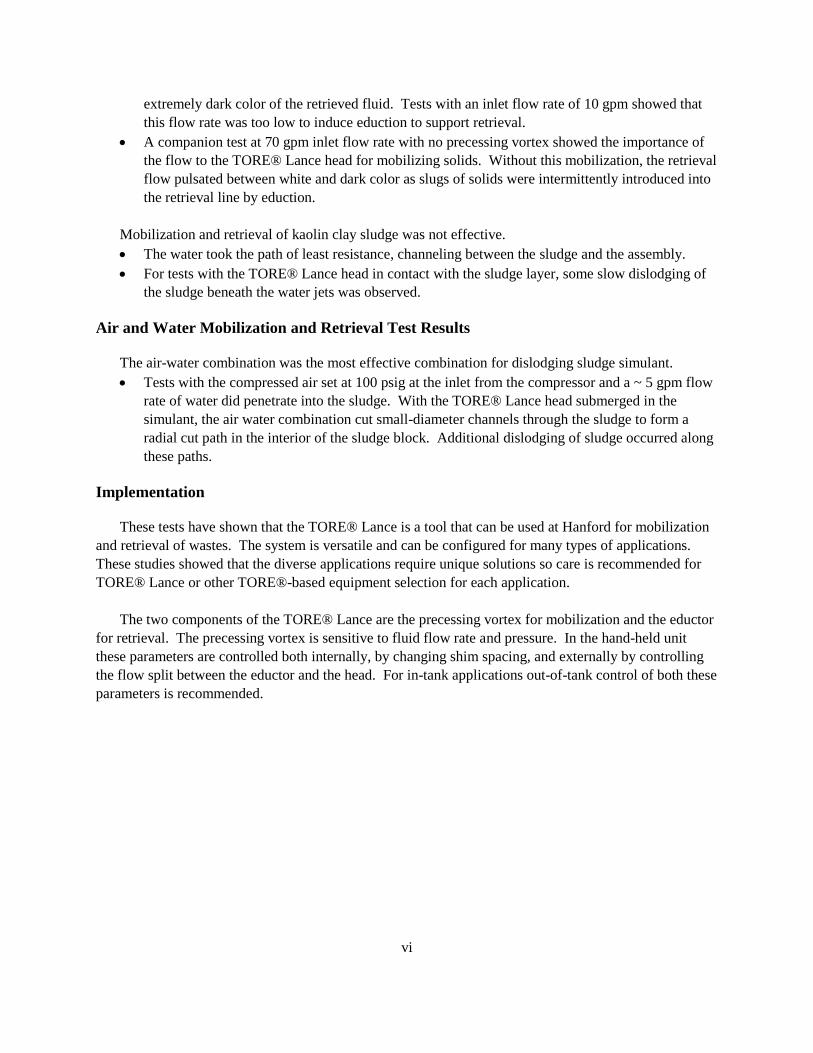
extremely dark color of the retrieved fluid. Tests with an inlet flow rate of 10 gpm showed that
this flow rate was too low to induce eduction to support retrieval.
A companion test at 70 gpm inlet flow rate with no precessing vortex showed the importance of
the flow to the TORE® Lance head for mobilizing solids. Without this mobilization, the retrieval
flow pulsated between white and dark color as slugs of solids were intermittently introduced into
the retrieval line by eduction.
Mobilization and retrieval of kaolin clay sludge was not effective.
The water took the path of least resistance, channeling between the sludge and the assembly.
For tests with the TORE® Lance head in contact with the sludge layer, some slow dislodging of
the sludge beneath the water jets was observed.
Air and Water Mobilization and Retrieval Test Results
The air-water combination was the most effective combination for dislodging sludge simulant.
Tests with the compressed air set at 100 psig at the inlet from the compressor and a ~ 5 gpm flow
rate of water did penetrate into the sludge. With the TORE® Lance head submerged in the
simulant, the air water combination cut small-diameter channels through the sludge to form a
radial cut path in the interior of the sludge block. Additional dislodging of sludge occurred along
these paths.
Implementation
These tests have shown that the TORE® Lance is a tool that can be used at Hanford for mobilization
and retrieval of wastes. The system is versatile and can be configured for many types of applications.
These studies showed that the diverse applications require unique solutions so care is recommended for
TORE® Lance or other TORE®-based equipment selection for each application.
The two components of the TORE® Lance are the precessing vortex for mobilization and the eductor
for retrieval. The precessing vortex is sensitive to fluid flow rate and pressure. In the hand-held unit
these parameters are controlled both internally, by changing shim spacing, and externally by controlling
the flow split between the eductor and the head. For in-tank applications out-of-tank control of both these
parameters is recommended.
vii
Contents
Acknowledgments ....................................................................................................................................... iii
Summary ....................................................................................................................................................... v
Compressed Air Mobilization and Retrieval......................................................................................... v
Water Mobilization and Retrieval ......................................................................................................... v
Air and Water Mobilization and Retrieval Test Results ...................................................................... vi
Implementation .................................................................................................................................... vi
1.0 Introduction ..................................................................................................................................... 1.1
1.1 TORE® Lance Technology ......................................................................................................... 1.1
1.2 Deployment at Hanford ............................................................................................................... 1.1
1.3 Objective of the TORE® Lance Evaluation ................................................................................ 1.2
2.0 Conclusions and Recommendations ............................................................................................... 2.1
2.1 Conclusions ................................................................................................................................. 2.1
2.1.1 Compressed Air Test Results ............................................................................................... 2.1
2.1.2 Water Test Results ............................................................................................................... 2.2
2.1.3 Air and Water Test Results .................................................................................................. 2.2
2.2 Parameter Evaluation................................................................................................................... 2.2
2.2.1 Mobilization Fluid ................................................................................................................ 2.2
2.2.2 Retrieval Method .................................................................................................................. 2.3
2.2.3 Stand-off Distance ................................................................................................................ 2.3
2.2.4 Angle of Inclination ............................................................................................................. 2.3
2.2.5 Simulant ............................................................................................................................... 2.3
2.2.6 Retrieval Height ................................................................................................................... 2.3
2.2.7 Type of Simulant Containment ............................................................................................ 2.3
2.3 Recommendations ....................................................................................................................... 2.3
3.0 TORE® Technology Operation ...................................................................................................... 3.1
3.1 TORE® Precessing Vortex Technology ..................................................................................... 3.1
3.2 TORE® Lance ............................................................................................................................. 3.2
3.3 TORE® Lance Operation ............................................................................................................ 3.4
3.3.1 Externally Adjustable Parameters ........................................................................................ 3.5
3.3.2 Internally Adjustable Parameters ......................................................................................... 3.6
3.4 TORE® Lance Demonstration at Vendor’s ................................................................................ 3.7
4.0 Experimental Configuration ............................................................................................................ 4.1
4.1 Test Facility ................................................................................................................................. 4.1
4.1.1 Equipment ............................................................................................................................ 4.2
4.1.1.1 Solids Separation System and Blower .............................................................................. 4.2
4.1.1.2 Weigh Controller .............................................................................................................. 4.2
4.1.1.3 Process Water Skid ........................................................................................................... 4.2
4.1.1.4 Compressor ....................................................................................................................... 4.3
4.1.2 Instrumentation .................................................................................................................... 4.3
4.2 Simulant Selection and Characterization ..................................................................................... 4.5
viii
4.2.1 241-C-104 Waste Properties ................................................................................................ 4.5
4.2.2 Recommended Simulant for MRS Factory Acceptance Test ............................................... 4.6
4.2.3 Simulants Selected for TORE® Lance Evaluation .............................................................. 4.6
4.2.3.1 Gravel and Sand................................................................................................................ 4.6
4.2.3.2 Kaolin ............................................................................................................................... 4.7
4.3 Test Matrix .................................................................................................................................. 4.7
5.0 TORE® Lance Mobilization and Retrieval of Gravel .................................................................... 5.1
5.1 Gravel Test Matrix ..................................................................................................................... 5.1
5.2 Gravel Test Observations ............................................................................................................ 5.2
5.2.1 Pneumatic Conveyance through TORE® Lance .................................................................. 5.2
5.2.1.1 GP00V6 Observations ...................................................................................................... 5.2
5.2.1.2 GP00V2 Observations ...................................................................................................... 5.3
5.2.1.3 GP00V0 Observations ...................................................................................................... 5.3
5.2.1.4 GP00VS Observations ...................................................................................................... 5.3
5.2.1.5 GP0090 Observations ....................................................................................................... 5.4
5.2.1.6 GP009S Observations ....................................................................................................... 5.4
5.2.2 TORE® Lance Operation with Air Eduction-Enhanced Conveyance ................................. 5.5
5.2.2.1 GP10V6 and GP10V2 Observations ................................................................................ 5.5
5.2.2.2 GP10V0 Observations ...................................................................................................... 5.5
5.2.2.3 GP10VS Observations ...................................................................................................... 5.6
5.2.2.4 GP1092 Observations ....................................................................................................... 5.6
5.2.2.5 GP1090 Observations ....................................................................................................... 5.7
5.2.2.6 GP109S Observations ....................................................................................................... 5.7
5.2.3 TORE® Lance Full Operation with Air Precessing Vortex Mobilization and Eduction-
Enhanced Conveyance ....................................................................................................................... 5.8
5.2.3.1 GP11V6 Observations ...................................................................................................... 5.8
5.2.3.2 GP11V2 Observations ...................................................................................................... 5.8
5.2.3.3 GP11V0 Observations ...................................................................................................... 5.8
5.2.3.4 GP11VS Observations ...................................................................................................... 5.9
5.2.3.5 GV11VSS Observations ................................................................................................. 5.10
5.2.3.6 GP119S Observations ..................................................................................................... 5.10
5.2.3.7 GP113S Observations ..................................................................................................... 5.11
5.2.3.8 GP116S Observations ..................................................................................................... 5.12
5.3 Gravel Test Results.................................................................................................................... 5.12
6.0 TORE® Lance Mobilization and Retrieval of Sand ....................................................................... 6.1
6.1 Sand Test Matrix ........................................................................................................................ 6.1
6.2 Sand Test Observations .............................................................................................................. 6.2
6.2.1 TORE® Lance Operation with No Head Feed or Blower Induced Pneumatic Conveyance 6.2
6.2.1.1 SZ10V6 Observations ....................................................................................................... 6.3
6.2.1.2 SZ10V2 Observations ....................................................................................................... 6.3
6.2.1.3 SZ10V0 Observations ....................................................................................................... 6.4
6.2.1.4 SZ10VS Observations ...................................................................................................... 6.4
6.2.1.5 SZ1092 Observations ....................................................................................................... 6.5
ix
6.2.1.6 SZ1090 Observations ....................................................................................................... 6.5
6.2.1.7 SZ109S Observations ....................................................................................................... 6.6
6.2.2 TORE® Lance Operation with Head Feed but No Pneumatic Conveyance ........................ 6.6
6.2.2.1 SZ11V6 Observations ....................................................................................................... 6.6
6.2.2.2 SZ11V2 Observations ....................................................................................................... 6.7
6.2.2.3 SZ11V0 Observations ....................................................................................................... 6.7
6.2.2.4 SZ11VS Observations ...................................................................................................... 6.8
6.2.2.5 SZ1196 Observations ....................................................................................................... 6.9
6.2.2.6 SZ1192 Observations ....................................................................................................... 6.9
6.2.2.7 SZ1190 Observations ..................................................................................................... 6.10
6.2.2.8 SZ119S Observations ..................................................................................................... 6.10
6.2.3 TORE® Lance Full Operation with Air ............................................................................. 6.10
6.2.3.1 SP11V6 Observations ..................................................................................................... 6.11
6.2.3.2 SP11V2 Observations ..................................................................................................... 6.11
6.2.3.3 SP11V0 Observations ..................................................................................................... 6.11
6.2.3.4 SP11VS Observations ..................................................................................................... 6.12
6.2.3.5 SP11VSS Observations .................................................................................................. 6.12
6.2.3.6 SP1196 Observations ...................................................................................................... 6.13
6.2.3.7 SP1192 Observations ...................................................................................................... 6.13
6.2.3.8 SP1190 Observations ...................................................................................................... 6.14
6.2.3.9 SP119S Observations ..................................................................................................... 6.15
6.2.3.10 SP113S Observations .................................................................................................. 6.16
6.2.3.11 SP116S Observations .................................................................................................. 6.17
6.3 Sand Test Results ...................................................................................................................... 6.17
7.0 TORE® Lance Mobilization and Retrieval of Sludge .................................................................... 7.1
7.1 Sludge Test Matrix ..................................................................................................................... 7.1
7.2 Sludge Test Observations ........................................................................................................... 7.3
7.2.1 TORE® Lance Operation with Extremely Strong Sludge Simulant .................................... 7.3
7.2.1.1 KP11V0 Observations ...................................................................................................... 7.3
7.2.1.2 KP11VS Observations ...................................................................................................... 7.3
7.2.1.3 KP21VS Observations ...................................................................................................... 7.4
7.2.2 TORE® Lance Full Operation with Air Precessing Vortex Mobilizing and Eductor-
Enhanced Conveyance for Retrieval of Sludge ................................................................................. 7.4
7.2.2.1 KP21V0 Observations ...................................................................................................... 7.5
7.2.2.2 KP21VS Observations ...................................................................................................... 7.5
7.2.2.3 KP21VSS Observations .................................................................................................... 7.6
7.2.2.4 KP219S Observations ....................................................................................................... 7.7
7.2.2.5 KP216S Observations ....................................................................................................... 7.7
7.2.2.6 KP2130 Observations ....................................................................................................... 7.8
7.2.3 TORE® Lance Full Operation with Combined Air and Water ............................................ 7.8
7.2.3.1 KP3100 ............................................................................................................................. 7.9
7.2.3.2 KP31V2 Observations ...................................................................................................... 7.9
7.2.3.3 KP31V0 Observations ...................................................................................................... 7.9
x
7.2.3.4 KP31VS Observations .................................................................................................... 7.10
7.2.3.5 KP313S Observations ..................................................................................................... 7.10
7.2.3.6 KP316S Observations ..................................................................................................... 7.11
7.2.3.7 KP319S Observations ..................................................................................................... 7.12
7.3 Sludge Test Results ................................................................................................................... 7.12
8.0 Larger-Scale TORE® Lance Evaluations ....................................................................................... 8.1
8.1 Test Matrix .................................................................................................................................. 8.1
8.2 Test Observations ........................................................................................................................ 8.2
8.2.1 Initial TORE® Lance Retrieval of Solids from a Drum ...................................................... 8.2
8.2.1.1 DSP11VS Observations Parts 1, 2 and 3 .......................................................................... 8.3
8.2.1.2 DSP00VS Observations .................................................................................................... 8.4
8.2.1.3 DSP10VS Observations .................................................................................................... 8.4
8.2.1.4 DSP31VS Observations .................................................................................................... 8.5
8.2.2 Evaluating Changes in Inlet Air Pressure ............................................................................ 8.5
8.2.2.1 DSP1105 Observations ..................................................................................................... 8.5
8.2.2.2 DSP11025 Observations ................................................................................................... 8.6
8.2.2.3 FSP11025 Observations ................................................................................................... 8.6
8.2.2.4 FSP11030 Observations ................................................................................................... 8.7
8.2.2.5 FSP11045 Observations ................................................................................................... 8.7
8.2.3 Fine Tuning TORE® Lance Operation ................................................................................ 8.7
8.2.3.1 FSZ1145 Test 1 Observations .......................................................................................... 8.8
8.2.3.2 FSZ1145 Test 2 Observations .......................................................................................... 8.8
8.2.3.3 FSZ1145 Test 3 Observations .......................................................................................... 8.8
8.2.3.4 BSZ1130 Test 4 Observations .......................................................................................... 8.9
8.2.3.5 BSZ1145 Test 5 Observations .......................................................................................... 8.9
8.2.3.6 FSZ1145 Test 6 Observations ........................................................................................ 8.10
8.2.3.7 BWZ1045 Test 7 Observations ...................................................................................... 8.10
8.2.3.8 BWZ1145 Test 8 Observations ...................................................................................... 8.11
8.3 Test Results ............................................................................................................................... 8.11
9.0 TORE® Lance Retrieval of Bulk Solids from a Drum ................................................................... 9.1
9.1 Test Matrix .................................................................................................................................. 9.1
9.2 Test Observations ........................................................................................................................ 9.2
9.2.1 Sand Mobilization and Retrieval from a Drum .................................................................... 9.2
9.2.1.1 DSP11VS Observations .................................................................................................... 9.2
9.2.1.2 DSZ11VS Observations ................................................................................................... 9.2
9.2.1.3 DSP31VS Observations .................................................................................................... 9.3
9.2.1.4 DSP21VS Observations .................................................................................................... 9.4
9.2.2 Evaluating Effects of Water Flow Rate on Water-Only Mobilization and Retrieval ........... 9.4
9.2.2.1 DSZ21VS10 Observations ............................................................................................... 9.4
9.2.2.2 DSZ21VS50 Observations ............................................................................................... 9.5
9.2.2.3 DSZ20VS70 Observations ............................................................................................... 9.6
9.2.2.4 DSZ21VS70 Observations ............................................................................................... 9.6
9.3 Test Results ................................................................................................................................. 9.7
xi
10.0 References ..................................................................................................................................... 10.1
11.0 Distribution ................................................................................................................................... 11.1

xiii
Figures
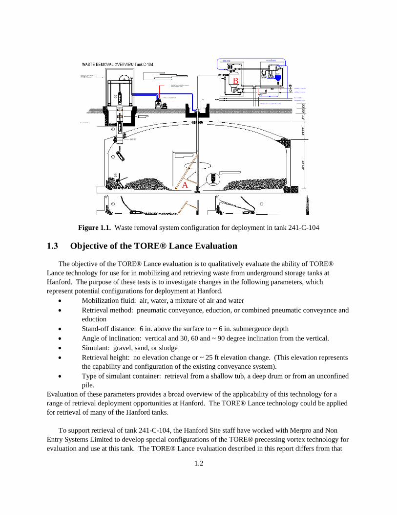
Figure 1.1. Waste removal system configuration for deployment in tank 241-C-104 .............................. 1.2
Figure 3.1. TORE® configuration for solids suspension and retrieval ...................................................... 3.1
Figure 3.2. Hand-held TORE® Lance component drawing ..................................................................... 3.2
Figure 3.3. TORE® Lance Parts List ........................................................................................................ 3.3
Figure 3.4. View of the TORE® Lance head showing the slits used to develop the precessing vortex ... 3.4
Figure 3.5. TORE® Lance performance curves. ...................................................................................... 3.5
Figure 3.6. TORE® Lance flow rate with and without bypassing flow to the head. ................................ 3.5
Figure 3.7. View inside the flow control manifold showing the connection between the upper and lower
ceramic pieces that line the inside of the eductor. .............................................................................. 3.6
Figure 3.8. Eductor ceramic liner showing black O-ring and white spacer. ............................................. 3.6
Figure 3.9. Plot showing how the spacer thickness affects the flow split between the eductor and the
TORE® Lance head. .......................................................................................................................... 3.7
Figure 3.10. Demonstration of operation of a 1-in. diameter TORE® Lance at the vendor’s facility. .... 3.8
Figure 4.1. TORE® Lance test configuration ........................................................................................... 4.1
Figure 4.2. Water skid diagram ................................................................................................................. 4.2
Figure 4.3. Properties of kaolin water simulants and comparison with sludge-type wastes ..................... 4.7
Table 4.4. Test number column definition for tests described in Sections 5, 6 and 7. .............................. 4.8
Table 4.5. Test number column definition for tests described in Section 8. ............................................. 4.8
Figure 5.1 Test GP00V6 Sequence May 31, 2002: Gravel simulant, pneumatic conveyance, no air or
water, no head feed, TORE® oriented vertically 6 in. above the simulant. ....................................... 5.3
Figure 5.2. Test GP00V2 Sequence May 31, 2002: Gravel simulant, pneumatic conveyance, no air or
water, no head feed, TORE® oriented vertically 2 in. above the simulant. ....................................... 5.3
Figure 5.3. Test GP00V0 Sequence May 31, 2002: Gravel simulant, pneumatic conveyance, no air or
water, no head feed, TORE® oriented vertically 0 in. above the simulant. ....................................... 5.3
Figure 5.4. Test GP00VS Sequence May 31, 2002: Gravel simulant, pneumatic conveyance, no air or
water, no head feed, TORE® oriented vertically with the head submerged in the simulant. ............. 5.4
Figure 5.5. Test GP0090 Sequence May 31, 2002: Gravel simulant, pneumatic conveyance, no air or
water, no head feed, TORE® oriented horizontally (90) 0 in. above the simulant. .......................... 5.4
Figure 5.6. Test GP009S Sequence May 31, 2002: Gravel simulant, pneumatic conveyance, no air or
water, no head feed, TORE® oriented horizontally (90) with the head submerged in the simulant. 5.5
Figure 5.7. Test GP10V0 Sequence May 31, 2002: Gravel simulant, pneumatic conveyance, air, no
water, no head feed, TORE® oriented vertically 0 in. above the simulant. ....................................... 5.6
Figure 5.8. Test GP10VS Sequence May 31, 2002: Gravel simulant, pneumatic conveyance, air, no
water, no head feed, TORE® oriented vertically with the head submerged in the simulant. ............. 5.6
Figure 5.9. Test GP1092 Sequence May 31, 2002: Gravel simulant, pneumatic conveyance, air, no water,
no head feed, TORE® oriented horizontally 2 in. above the simulant. .............................................. 5.7
Figure 5.10. Test GP1090 Sequence May 31, 2002: Gravel simulant, pneumatic conveyance, air, no
water, no head feed, TORE® oriented horizontally 0 in. above the simulant. ................................... 5.7
Figure 5.11. Test GP109S Sequence May 31, 2002: Gravel simulant, pneumatic conveyance, air, no
water, no head feed, TORE® oriented horizontally with the head submerged in the simulant. ......... 5.7
xiv
Figure 5.12. Test GP11V6 Sequence May 31, 2002: Gravel simulant, pneumatic conveyance, air, no
water, head feed, TORE® oriented vertically 6 in. above the simulant. ............................................ 5.8
Figure 5.13. Test GP11V0 Sequence May 31, 2002: Gravel simulant, pneumatic conveyance, air, no
water, head feed, TORE® oriented vertically 2 in. above the simulant. ............................................ 5.8
Figure 5.14. Test GP11V0 Sequence May 31, 2002: Gravel simulant, pneumatic conveyance, air, no
water, head feed, TORE® oriented vertically 0 in. above the simulant. ............................................ 5.9
Figure 5.15. Test GP11VS Sequence May 31, 2002: Gravel simulant, pneumatic conveyance, air, no
water, head feed, TORE® oriented vertically with head submerged in the simulant ......................... 5.9
Figure 5.16. Test GP11VSS Sequence May 31, 2002: Gravel simulant, pneumatic conveyance, air, no
water, head feed, TORE® oriented vertically with head submerged deeper into the simulant. ....... 5.10
Figure 5.17. Test GP119S Sequence May 31, 2002: Gravel simulant, pneumatic conveyance, air, no
water, head feed, TORE® oriented horizontally (at 90) with the head submerged in the simulant.
.......................................................................................................................................................... 5.11
Figure 5.18. Test GP113S Sequence May 31, 2002: Gravel simulant, pneumatic conveyance, air, no
water, head feed, TORE® oriented at 30 with the head submerged in the simulant. ..................... 5.11
Figure 5.19. Test GP116S Sequence May 31, 2002: Gravel simulant, pneumatic conveyance, air, no
water, head feed, TORE® oriented at 60 with the head submerged in the simulant. ..................... 5.12
Figure 6.1. Test SZ10V6 Sequence June 3, 2002: Sand simulant, no pneumatic conveyance, air, no water,
no head feed, TORE® oriented vertically 6 in. above the simulant. .................................................. 6.3
Figure 6.2. Disassembly and removal of solids from the TORE® Lance manifold. ................................ 6.3
Figure 6.3. Test SZ10V2 Sequence June 3, 2002: Sand simulant, no pneumatic conveyance, air, no water,
no head feed, TORE® oriented vertically 2 in. above the simulant. .................................................. 6.4
Figure 6.4. Test SZ10V0 Sequence June 3, 2002: Sand simulant, no pneumatic conveyance, air, no water,
no head feed, TORE® oriented vertically 0 in. above the simulant. .................................................. 6.4
Figure 6.5. Test SZ10VS Sequence June 3, 2002: Sand simulant, no pneumatic conveyance, air, no
water, no head feed, TORE® oriented vertically with head submerged in the simulant. ................... 6.5
Figure 6.6. Test SZ1092 Sequence June 3, 2002: Sand simulant, no pneumatic conveyance, air, no water,
no head feed, TORE® oriented horizontally (at 90) 2 in. above the simulant. ................................. 6.5
Figure 6.7. Test SZ1090 Sequence June 3, 2002: Sand simulant, pneumatic conveyance, air, no water, no
head feed, TORE® oriented horizontally (at 90) 0 in. above the simulant. ...................................... 6.6
Figure 6.8. Test SZ109S Sequence June 3, 2002: Sand simulant, no pneumatic conveyance, air, no water,
no head feed, TORE® oriented horizontally (at 90) with head submerged in the simulant. ............ 6.6
Figure 6.9. Test SZ11V6 Sequence June 3, 2002: Sand simulant, no pneumatic conveyance, air, no water,
head feed, TORE® oriented vertically 6 in. above the simulant. ....................................................... 6.7
Figure 6.10. Test SZ11V2 Sequence June 3, 2002: Sand simulant, no pneumatic conveyance, air, no
water, head feed, TORE® oriented vertically 2 in. above the simulant. ............................................ 6.7
Figure 6.11. Test SZ11V0 Sequence June 3, 2002: Sand simulant, no pneumatic conveyance, air, no
water, head feed, TORE® oriented vertically 0 in. above the simulant. ............................................ 6.8
Figure 6.12. Test SZ11VS Sequence June 3, 2002: Sand simulant, no pneumatic conveyance, air, no
water, head feed, TORE® oriented vertically submerged deeper into the simulant........................... 6.8
Figure 6.13. Test SZ1196 Sequence June 3, 2002: Sand simulant, no pneumatic conveyance, air, no
water, head feed, TORE® oriented horizontally (at 90) with head 6 in. above the simulant. .......... 6.9
Figure 6.14. Test SZ1192 Sequence June 3, 2002: Sand simulant, no pneumatic conveyance, air, no
water, head feed, TORE® oriented horizontally (at 90) with head 2 in. above the simulant. .......... 6.9

xv
Figure 6.15. Test SZ1190 Sequence June 3, 2002: Sand simulant, no pneumatic conveyance, air, no
water, head feed, TORE® oriented horizontally (at 90) with head 0 in. above the simulant. ........ 6.10
Figure 6.16. Test SZ119S Sequence June 3, 2002: Sand simulant, no pneumatic conveyance, air, no
water, head feed, TORE® oriented horizontally (at 90) with head submerged in the simulant. .... 6.10
Figure 6.17. Test SP11V6 Sequence June 4, 2002: Sand simulant, pneumatic conveyance, air, no water,
head feed, TORE® oriented vertically 6 in. above the simulant. ..................................................... 6.11
Figure 6.17. Test SP11V2 Sequence June 4, 2002: Sand simulant, pneumatic conveyance, air, no water,
head feed, TORE® oriented vertically 2 in. above the simulant. ..................................................... 6.11
Figure 6.18. Test SP11V0 Sequence June 4, 2002: Sand simulant, pneumatic conveyance, air, no water,
head feed, TORE® oriented vertically 0 in. above the simulant. ..................................................... 6.12
Figure 6.19. Test SP11VS Sequence June 4, 2002: Sand simulant, pneumatic conveyance, air, no water,
head feed, TORE® oriented vertically submerged in the simulant. ................................................. 6.12
Figure 6.20. Test SP11VSS Sequence June 4, 2002: Sand simulant, pneumatic conveyance, air, no water,
head feed, TORE® oriented vertically submerged deeper into the simulant. .................................. 6.13
Figure 6.21. Test SP1196 Sequence June 4, 2002: Sand simulant, pneumatic conveyance, air, no water,
head feed, TORE® oriented horizontally, suspended 6 in. above the simulant. .............................. 6.13
Figure 6.22. Test SP1192 Sequence June 4, 2002: Sand simulant, pneumatic conveyance, air, no water,
head feed, TORE® oriented horizontally (at 90) with head 2 in. above the simulant. ................... 6.14
Figure 6.23. Test SP1190 Sequence June 4, 2002: Sand simulant, pneumatic conveyance, air, no water,
head feed, TORE® oriented horizontally (at 90) with head 0 in. above the simulant. ................... 6.15
Figure 6.24. Test SP119S Sequence June 4, 2002: Sand simulant, pneumatic conveyance, air, no water,
head feed, TORE® oriented horizontally (at 90) with head submerged in the simulant. ............... 6.16
Figure 6.25. Test SP113S Sequence June 4, 2002: Sand simulant, pneumatic conveyance, air, no water,
head feed, TORE® oriented at 30 with head submerged in the simulant. ...................................... 6.17
Figure 6.26. Test SP116S Sequence June 4, 2002: Sand simulant, pneumatic conveyance, air, no water,
head feed, TORE® oriented at 60 with head submerged in the simulant. ...................................... 6.17
Figure 7.1. Test KP11V0 Sequence June 5, 2002: Kaolin clay simulant, pneumatic conveyance, air, no
water, head feed, TORE® oriented vertically with head 0 in. above the simulant. ............................ 7.3
Figure 7.2. Test KP11VS Sequence June 5, 2002: Kaolin clay simulant, pneumatic conveyance, air, no
water, head feed, TORE® oriented vertically with head submerged in the simulant. ........................ 7.4
Figure 7.3. Test KP21VS Sequence June 5, 2002: Kaolin clay simulant, pneumatic conveyance, air,
water, head feed, TORE® oriented vertically with head submerged in the simulant. ........................ 7.4
Figure 7.4. Test KP21V0 (updated from KP11V0) (2nd
time with new clay) Sequence June 18, 2002:
Kaolin clay simulant, pneumatic conveyance, no air, water, head feed, TORE® oriented vertically
with head 0 in. above the simulant. .................................................................................................... 7.5
Figure 7.5. Test KP21VS (updated from KP1VS) (2nd
time with new clay) Sequence June 18, 2002:
Kaolin clay simulant, pneumatic conveyance, no air, water, head feed, TORE® oriented vertically
with head submerged in the simulant. ................................................................................................ 7.6
Figure 7.6. Test KP21VSS (updated from KP11VSS) Sequence June 18, 2002: Kaolin clay simulant,
pneumatic conveyance, no air, water, head feed, TORE® oriented vertically with head submerged
deeper in the simulant. ........................................................................................................................ 7.6
Figure 7.7. Test KP219S (updated from KP119S) Sequence June 18, 2002: Kaolin clay simulant,
pneumatic conveyance, no air, water, head feed, TORE® oriented horizontally (at 90) with head
submerged in the simulant. ................................................................................................................. 7.7
xvi
Figure 7.8. Test KP216S (updated from KP116S) Sequence June 18, 2002: Kaolin clay simulant,
pneumatic conveyance, no air, water, head feed, TORE® oriented at 60 with head submerged in the
simulant. ............................................................................................................................................. 7.8
Figure 7.9. Test KP213S Sequence June 18, 2002: Kaolin clay simulant, pneumatic conveyance, no air,
water, head feed, TORE® oriented at 30 with head submerged into the simulant. .......................... 7.8
Figure 7.10. Flow of water through the TORE® Lance head. .................................................................. 7.9
Figure 7.11. Test KP31V2 (updated from KP12V2)Sequence June 18, 2002: Kaolin clay simulant,
pneumatic conveyance, air, water, head feed, TORE® oriented at vertically with head 2 in. above the
simulant. ............................................................................................................................................. 7.9
Figure 7.12. Test KP31V0 (updated from KP12V0) Sequence June 18, 2002: Kaolin clay simulant,
pneumatic conveyance, air, water, head feed, TORE® oriented at vertically with head 0 in. above the
simulant. ........................................................................................................................................... 7.10
Figure 7.13. Test KP31VS (updated from KP12VS) Sequence June 18, 2002: Kaolin clay simulant,
pneumatic conveyance, air, water, head feed, TORE® oriented at vertically with head submerged in
the simulant. ...................................................................................................................................... 7.10
Figure 7.14. Test KP313S (updated from KP123S) Sequence June 18, 2002: Kaolin clay simulant,
pneumatic conveyance, air, water, head feed, TORE® oriented at 30 with head submerged in the
simulant. ........................................................................................................................................... 7.11
Figure 7.15. Test KP316S (updated from KP126S) Sequence June 18, 2002: Kaolin clay simulant,
pneumatic conveyance, air, water, head feed, TORE® oriented at 60 with head submerged in the
simulant. ........................................................................................................................................... 7.11
Figure 7.16. Test KP319S Sequence June 18, 2002: Kaolin clay simulant, pneumatic conveyance, air,
water, head feed, TORE® oriented at horizontally (at 90) with head submerged in the simulant. 7.12
Figure 8.1. Test DSP11VS (a+b) Sequence July 22, 2002: Wet sand/water simulant, pneumatic
conveyance, air, no water, head feed, TORE® oriented vertically with head submerged into the
simulant. ............................................................................................................................................. 8.3
Figure 8.2. Test DSP11VS (c) Sequence July 22, 2002: Wet sand/water simulant, pneumatic conveyance,
air, no water, head feed, TORE® oriented vertically with head submerged into the simulant. ......... 8.4
Figure 8.3. Test DSP00VS Sequence July 22, 2002: Wet sand/water simulant, pneumatic conveyance, no
air, no water, no head feed, TORE® oriented vertically with head submerged into the simulant. .... 8.4
Figure 8.4. Test DSP10VS Sequence July 22, 2002: Wet sand/water simulant, pneumatic conveyance,
air, no water, no head feed, TORE® oriented vertically with head submerged into the simulant. .... 8.5
Figure 8.5. Test DSP11005 Sequence July 24, 2002: Wet sand simulant, pneumatic conveyance, air, no
water, head feed, TORE® oriented vertically with head submerged into the simulant. ..................... 8.6
Figure 8.6. Test DSP11025 Sequence July 24, 2002: Wet sand/water simulant, pneumatic conveyance,
air, no water, head feed, TORE® oriented vertically with head submerged in the simulant. ............ 8.6
Figure 8.7. Test FSP11025 (updated from DSP11025-Floor Sequence) July 24, 2002: Wet sand/water
simulant, pneumatic conveyance, air, no water, head feed, TORE® oriented vertically with head 0 in.
above the simulant. (25 psig.) ............................................................................................................. 8.6
Figure 8.8. Test FSP11030 (updated from DSP11030-Floor Sequence) July 24, 2002: Wet sand/water
simulant, pneumatic conveyance, air, no water, head feed, TORE® oriented vertically with head 0 in.
above the simulant. (30 psig.) ............................................................................................................. 8.7
xvii
Figure 8.9. Test FSP11045 (updated from DSP11045-Floor Sequence) July 24, 2002: Wet sand/water
simulant, pneumatic conveyance, air, no water, head feed, TORE® oriented vertically with head 0 in.
above the simulant. (45 psig) .............................................................................................................. 8.7
Figure 8.10. FSZ1145 Test 1 Sequence July 31, 2002: Wet sand/water simulant on floor, no pneumatic
conveyance, air, no water, head feed, TORE® operated manually. ................................................... 8.8
Figure 8.11. FSZ1145 Test 2 Sequence July 31, 2002: Wet sand/water simulant on floor, no pneumatic
conveyance, air, no water, head feed, TORE® operated manually. ................................................... 8.8
Figure 8.12. FSZ1145 Test 3 Sequence July 31, 2002: Wet sand/water simulant on floor, no pneumatic
conveyance, air, no water, head feed, TORE® operated manually. ................................................... 8.9
Figure 8.13. BSZ1130 Test 4 Sequence July 31, 2002: Wet sand/water simulant in bucket, no pneumatic
conveyance, air (at 30psig), no water, head feed, TORE® operated manually. ................................. 8.9
Figure 8.14. BSZ1145 Test 5 Sequence July 31, 2002: Wet sand/water simulant in bucket, no pneumatic
conveyance, air (at 45 psig), no water, head feed, TORE® operated manually. .............................. 8.10
Figure 8.15. FSZ1145 Test 6 Sequence July 31, 2002: Wet sand/water simulant in pile on floor, no
pneumatic conveyance, air, no water, head feed, TORE® operated manually. ............................... 8.10
Figure 8.16. BWZ1045 Test 7 Sequence July 31, 2002: Water without solids in bucket, no pneumatic
conveyance, air, no water, no head feed, TORE® operated manually. ............................................ 8.11
Figure 8.17. BWZ1145 Test 8 Sequence July 31, 2002: Water without solids in bucket, no pneumatic
conveyance, air, no water, head feed, TORE® operated manually. ................................................. 8.11
Figure 9.1. Test DSP11VS (updated from DSP01VS) Sequence August 7, 2002: Wet sand/water
simulant, pneumatic conveyance, air, no water, head feed, TORE® oriented vertically with head
submerged into the simulant. .............................................................................................................. 9.2
Figure 9.2. Test DSZ01VS Sequence August 7, 2002: Wet sand/water simulant, no pneumatic
conveyance, air, no water, head feed, TORE® oriented vertically with head submerged into the
simulant. ............................................................................................................................................. 9.3
Figure 9.3. Test DSP31VS (updated from DSP21VS) Sequence August 7, 2002: Wet sand/water
simulant, pneumatic conveyance, air, water, head feed, TORE® oriented vertically with head
submerged into the simulant. .............................................................................................................. 9.3
Figure 9.4. Test DSP21VS (updated from DSP11VS) Sequence August 7, 2002: Wet sand/water
simulant, pneumatic conveyance, no air, water, head feed, TORE® oriented vertically with head
submerged into the simulant. .............................................................................................................. 9.4
Figure 9.5. Test DSZ21VS10 (updated from DSZ11VS10) Sequence August 7, 2002: Wet sand/water
simulant, no pneumatic conveyance, no air, water, head feed, TORE® oriented vertically with head
submerged into the simulant. (10 gpm water flow rate.). .................................................................. 9.5
Figure 9.6. Test DSZ21VS50 (updated from DSZ11VS50) Sequence August 7, 2002: Wet sand/water
simulant, no pneumatic conveyance, no air, water, head feed, TORE® oriented vertically with head
submerged into the simulant. (50 gpm water flow rate). .................................................................... 9.5
Figure 9.7. Test DSZ20VS70 (update of DSZ10VS70) Sequence August 7, 2002: Wet sand/water
simulant, no pneumatic conveyance, no air, water, no head feed, TORE® oriented vertically with
head submerged into the simulant. (70 gpm). .................................................................................... 9.6
Figure 9.8. Test DSZ21VS70 (update of DSZ11VS70) Sequence August 7, 2002: Wet sand/water
simulant, no pneumatic conveyance, no air, water, head feed, TORE® oriented vertically with head
submerged into the simulant. (70 gpm). ............................................................................................ 9.7
xviii
Tables
Table 3.1. TORE® Lance operating conditions. ....................................................................................... 3.4
Table 4.1. TORE® Lance process measurements .................................................................................... 4.3
Table 4.2. Instrumentation ........................................................................................................................ 4.4
Table 4.3. Sand and gravel physical properties ......................................................................................... 4.7
Table 4.4. Physical properties of kaolin-water sludge simulants .............................................................. 4.7
Table 5.1 Test matrix for evaluation of TORE® Lance mobilizing and retrieval of gravel. .................... 5.1
Table 5.2. Results of TORE® Lance retrieval of gravel using compressed air enhanced mobilizing and
conveyance. ...................................................................................................................................... 5.13
Table 6.1 Test matrix for evaluation of TORE® Lance mobilizing and retrieval of sand. ...................... 6.1
Table 6.2. Results of TORE® Lance retrieval of sand using compressed air enhanced mobilizing and
conveyance. ...................................................................................................................................... 6.19
Table 7.1. Test matrix for evaluation of TORE® Lance mobilizing and retrieval of sludge. .................. 7.1
Table 7.2. Results of TORE® Lance retrieval of sludge using air, water, and air-water for mobilizing
coupled with pneumatic conveyance. ............................................................................................... 7.13
Table 8.1. Test matrix for TORE® Lance larger-scale evaluations. ......................................................... 8.1
Table 8.2. Results of TORE® Lance mobilizing and retrieval of sand in confined and unconfined
configurations ................................................................................................................................... 8.12
Table 9.1. Test matrix for TORE® Lance larger-scale evaluations. ......................................................... 9.1
Table 9.2. Results of TORE® Lance mobilizing and retrieval of bulk solids from a drum ..................... 9.8
1.1
1.0 Introduction
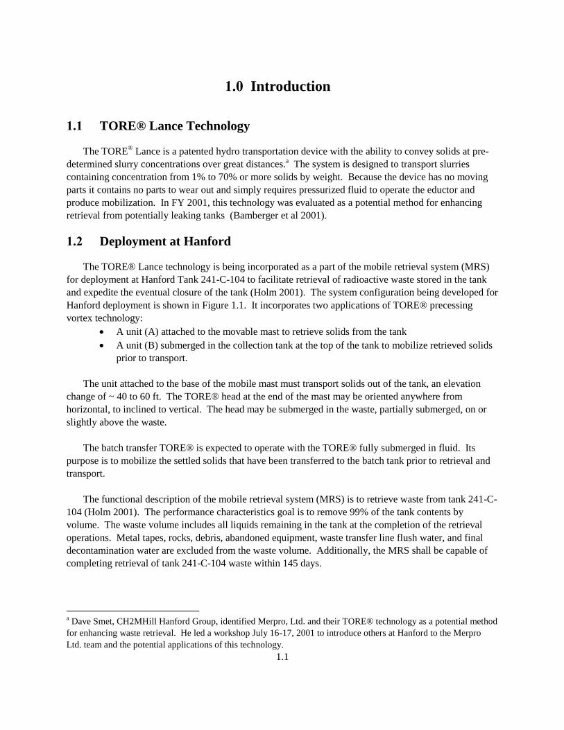
1.1 TORE® Lance Technology
The TORE® Lance is a patented hydro transportation device with the ability to convey solids at pre-
determined slurry concentrations over great distances.a The system is designed to transport slurries
containing concentration from 1% to 70% or more solids by weight. Because the device has no moving
parts it contains no parts to wear out and simply requires pressurized fluid to operate the eductor and
produce mobilization. In FY 2001, this technology was evaluated as a potential method for enhancing
retrieval from potentially leaking tanks (Bamberger et al 2001).
1.2 Deployment at Hanford
The TORE® Lance technology is being incorporated as a part of the mobile retrieval system (MRS)
for deployment at Hanford Tank 241-C-104 to facilitate retrieval of radioactive waste stored in the tank
and expedite the eventual closure of the tank (Holm 2001). The system configuration being developed for
Hanford deployment is shown in Figure 1.1. It incorporates two applications of TORE® precessing
vortex technology:
A unit (A) attached to the movable mast to retrieve solids from the tank
A unit (B) submerged in the collection tank at the top of the tank to mobilize retrieved solids
prior to transport.
The unit attached to the base of the mobile mast must transport solids out of the tank, an elevation
change of ~ 40 to 60 ft. The TORE® head at the end of the mast may be oriented anywhere from
horizontal, to inclined to vertical. The head may be submerged in the waste, partially submerged, on or
slightly above the waste.
The batch transfer TORE® is expected to operate with the TORE® fully submerged in fluid. Its
purpose is to mobilize the settled solids that have been transferred to the batch tank prior to retrieval and
transport.
The functional description of the mobile retrieval system (MRS) is to retrieve waste from tank 241-C-
104 (Holm 2001). The performance characteristics goal is to remove 99% of the tank contents by
volume. The waste volume includes all liquids remaining in the tank at the completion of the retrieval
operations. Metal tapes, rocks, debris, abandoned equipment, waste transfer line flush water, and final
decontamination water are excluded from the waste volume. Additionally, the MRS shall be capable of
completing retrieval of tank 241-C-104 waste within 145 days.
a Dave Smet, CH2MHill Hanford Group, identified Merpro, Ltd. and their TORE® technology as a potential method
for enhancing waste retrieval. He led a workshop July 16-17, 2001 to introduce others at Hanford to the Merpro
Ltd. team and the potential applications of this technology.
1.2
Figure 1.1. Waste removal system configuration for deployment in tank 241-C-104
1.3 Objective of the TORE® Lance Evaluation
The objective of the TORE® Lance evaluation is to qualitatively evaluate the ability of TORE®
Lance technology for use for in mobilizing and retrieving waste from underground storage tanks at
Hanford. The purpose of these tests is to investigate changes in the following parameters, which
represent potential configurations for deployment at Hanford.
Mobilization fluid: air, water, a mixture of air and water
Retrieval method: pneumatic conveyance, eduction, or combined pneumatic conveyance and
eduction
Stand-off distance: 6 in. above the surface to ~ 6 in. submergence depth
Angle of inclination: vertical and 30, 60 and ~ 90 degree inclination from the vertical.
Simulant: gravel, sand, or sludge
Retrieval height: no elevation change or ~ 25 ft elevation change. (This elevation represents
the capability and configuration of the existing conveyance system).
Type of simulant container: retrieval from a shallow tub, a deep drum or from an unconfined
pile.
Evaluation of these parameters provides a broad overview of the applicability of this technology for a
range of retrieval deployment opportunities at Hanford. The TORE® Lance technology could be applied
for retrieval of many of the Hanford tanks.
To support retrieval of tank 241-C-104, the Hanford Site staff have worked with Merpro and Non
Entry Systems Limited to develop special configurations of the TORE® precessing vortex technology for
evaluation and use at this tank. The TORE® Lance evaluation described in this report differs from that
A
B

1.3
project. This investigation focuses on evaluating the ability of a commercially available hand-held
TORE® Lance for approximating these applications at Hanford. Some of the results from this
investigation may support the equipment deployment at tank 241-C-104, others may not be relevant to
that tank based on differences in configuration, deployment method, dislodging and retrieval fluid,
retrieval method, or simulant.

2.1
2.0 Conclusions and Recommendations
Conclusions and recommendations based on tests conducted to evaluate the operation of the hand-
held TORE® Lance for retrieval of gravel, sand, and sludge simulants are presented.
2.1 Conclusions
Three process fluid combination for TORE® Lance operation were evaluated for mobilization and
retrieval of granular sand and gravel and kaolin clay sludge:
Compressed air mobilization and eduction
Water mobilization and eduction
Air and water mixture for mobilization and eduction.
Tests were conducted to evaluate several types of retrieval:
Stationary retrieval of simulant from a tub
Bulk mobilization and retrieval of simulant from a drum
Unconfined mobilization and dislodging of simulant from the floor.
Each of these evaluations uncovered useful configurations applicable for mobilization and retrieval of
granular and sludge simulants. Details are described below.
2.1.1 Compressed Air Test Results
Stationary mobilization and retrieval tests conducted using gravel and sand simulants showed that
The zone of influence of the mobilizing fluid from the TORE® Lance head was ~ 18 in. in
diameter for tests conducted with the TORE® Lance head in contact with or submerged in the
simulant. This was observed with the head oriented vertically or at angles of 30, 60 or ~ 90 deg
from the vertical. This measured zone of influence for the precessing vortex confirms predictions
by Parkinson and Delves (1999) that the diameter of the zone of influence should be 6 times the
diameter of the discharge line. The TORE® Lane tested had a 2-in. diameter discharge line
attached to a 3-in. diameter fitting.
When compared to a baseline of pneumatic conveyance, addition of compressed air eduction
coupled with pneumatic conveyance significantly enhances retrieval rate.
When compared to a baseline of air eduction coupled with pneumatic conveyance, addition of the
precessing vortex significantly enhances solids mobilization and provides a more uniform loading
of particulate in the retrieved stream.
Tests of retrieval of sand from a drum showed that:
Optimal solids retrieval rates were obtained when the inlet air pressure from the compressor was
set at 45 psig. At this condition, the average retrieval rate observed was ~ 20 lbm/min; the peak
retrieval rate obtained was ~ 45 lbm/min in these short duration tests.
Retrieval of kaolin clay sludge using compressed air was not observed.
2.2
During these tests the compressed air emanating from the TORE® Lance head took the path of
least resistance, channeling between the sludge and the TORE® Lance tube or the sludge and the
sides of the container. After this occurred no additional dislodging of sludge was observed.
2.1.2 Water Test Results
Tests with water used for eduction and mobilization were conducted both with the pneumatic
conveyance line attached and with no pneumatic conveyance with the flow routed through a short hose
attached to the TORE® Lance discharge and discharged directly to tank containment.
The high water flow rate through the eductor tended to overwhelm the retrieval capability of the
pneumatic conveyance line (a limitation of the existing conveyance system).
Retrieval tests with the pneumatic conveyance line removed showed excellent qualitative
mobilization and retrieval at inlet water flow rates of 50 and 70 gpm. The retrieved flow was
steady and significant amounts of solids were transported as indicated by the extremely dark color
of the retrieved fluid. Tests with an inlet flow rate of 10 gpm showed that this flow rate was too
low to induce retrieval.
A companion test at 70 gpm inlet flow rate with no precessing vortex showed the importance of
the flow to the TORE® Lance head for mobilizing solids. Without this mobilization, the retrieval
flow pulsated between white and dark color as slugs of solids were intermittently introduced into
the retrieval line by eduction only.
Mobilization and retrieval of kaolin clay sludge was not effective.
The water took the path of least resistance, channeling between the sludge and the assembly.
For tests with the TORE® Lance head in contact with the sludge layer, some slow dislodging of
the sludge beneath the water jets was observed.
2.1.3 Air and Water Test Results
The air-water combination was the most effective combination for dislodging sludge simulant.
Tests were conducted with the compressed air set at 100 psig at the inlet from the compressor and
a ~ 5 gpm flow rate of water. With the TORE® Lance head submerged in the simulant, the air
water combination cut small-diameter channels through the sludge to form a radial cut path in the
interior of the sludge block. Additional dislodging of sludge occurred along these paths. No
evidence of development of a precessing vortex was observed
2.2 Parameter Evaluation
A brief synopsis for each of the parameters follows.
2.2.1 Mobilization Fluid
Three process fluids: air, water, and an air-water combination were considered for mobilization. Air
or water worked well for mobilizing sand or gravel. The air-water combination worked best for sludge
mobilization.
2.3
2.2.2 Retrieval Method
The retrieval methods evaluated included pneumatic conveyance, eduction or a combination of
pneumatic conveyance and eduction. Pneumatic conveyance performance was significantly enhanced by
the addition of compressed air eduction. Pneumatic conveyance performance was significantly degraded
by the addition of water eduction. Water eduction worked well when the pneumatic conveyance line was
removed and flow was directly discharged through a short hose attached to the discharge of the TORE®
Lance.
2.2.3 Stand-off Distance
The TORE® Lance performance was best when the TORE® Lance head was either submerged or in
contact with the simulant. Operation with a 2 in. or greater spacing between the head and the simulant
surface was not effective.
2.2.4 Angle of Inclination
The TORE® Lance orientation was evaluated with it oriented vertically or at angles of 30, 60, or ~ 90
deg from the vertical. The most uniform zone of influence was obtained with the unit oriented vertically.
At other orientations, the zone of influence changed from a circle to a slit (see Figures 6.23 or 6.24) with
the range unchanged by orientation.
2.2.5 Simulant
Three simulants: gravel, sand, and sludge were evaluated for combined mobilization and retrieval
using the TORE® Lance. Air mobilization and retrieval was most effective for use with sand or gravel, a
combination of air and water for mobilization was most effective for use with sludge. Water-induced
mobilization and retrieval was not as effective because excess water volume overloaded the pneumatic
conveyance system and hindered retrieval.
2.2.6 Retrieval Height
The retrieval height significantly affects the method of retrieval. This parameter must be analyzed for
each application to ensure that adequate transport can be provided.
2.2.7 Type of Simulant Containment
The TORE® Lance was able to retrieve both confined and unconfined sand and gravel simulants.
The depth of the head submergence in the material must be considered for each type of simulant
containment.
2.3 Recommendations
These tests have shown that the TORE® Lance is a tool that can be used at Hanford for mobilization
and retrieval of wastes. The system is versatile and can be configured for many types of applications.
2.4
These studies showed that the diverse applications require unique solutions so care is recommended in
TORE® Lance or TORE® equipment selection for each unique application.
The two components of the TORE® Lance are the precessing vortex inducing head for mobilizing
and the eductor for retrieval. The precessing vortex is sensitive to fluid flow rate and pressure. In the
hand-held TORE® Lance unit these parameters are controlled both internally, by changing shim spacing,
and externally by controlling the flow split between the eductor and the head. For in-tank applications
out-of-tank control of both these parameters is recommended.
3.1
3.0 TORE® Technology Operation
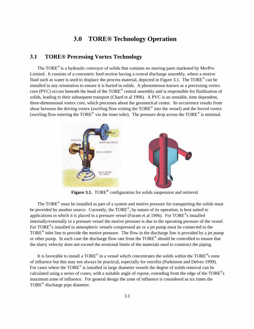
3.1 TORE® Precessing Vortex Technology
The TORE®
is a hydraulic conveyor of solids that contains no moving parts marketed by MerPro
Limited. It consists of a concentric feed section having a central discharge assembly, where a motive
fluid such as water is used to displace the process material, depicted in Figure 3.1. The TORE®
can be
installed in any orientation to ensure it is buried in solids. A phenomenon known as a precessing vortex
core (PVC) occurs beneath the head of the TORE® central assembly and is responsible for fluidization of
solids, leading to their subsequent transport (Chard et al 1996). A PVC is an unstable, time dependent,
three-dimensional vortex core, which precesses about the geometrical center. Its occurrence results from
shear between the driving vortex (swirling flow exiting the TORE® into the vessel) and the forced vortex
(swirling flow entering the TORE® via the inner tube). The pressure drop across the TORE
® is minimal.
Figure 3.1. TORE
® configuration for solids suspension and retrieval
The TORE® must be installed as part of a system and motive pressure for transporting the solids must
be provided by another source. Currently, the TORE®, by nature of its operation, is best suited to
applications in which it is placed in a pressure vessel (Faram et al 1996). For TORE®s installed
internally/externally in a pressure vessel the motive pressure is due to the operating pressure of the vessel.
For TORE®s installed in atmospheric vessels compressed air or a jet pump must be connected to the
TORE® inlet line to provide the motive pressure. The flow in the discharge line is provided by a jet pump
or other pump. In each case the discharge flow rate from the TORE® should be controlled to ensure that
the slurry velocity does not exceed the erosional limits of the materials used to construct the piping.
It is favorable to install a TORE® in a vessel which concentrates the solids within the TORE
®s zone
of influence but this may not always be practical, especially for retrofits (Parkinson and Delves 1999).
For cases where the TORE® is installed in large diameter vessels the degree of solids removal can be
calculated using a series of cones, with a suitable angle of repose, extending from the edge of the TORE®s
maximum zone of influence. For general design the zone of influence is considered as six times the
TORE® discharge pipe diameter.
3.2
3.2 TORE® Lance
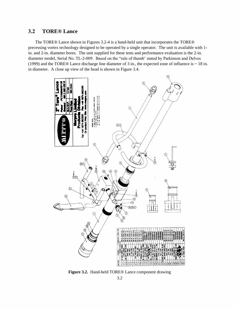
The TORE® Lance shown in Figures 3.2-4 is a hand-held unit that incorporates the TORE®
precessing vortex technology designed to be operated by a single operator. The unit is available with 1-
in. and 2-in. diameter bores. The unit supplied for these tests and performance evaluation is the 2-in.
diameter model, Serial No. TL-2-009. Based on the “rule of thumb’ stated by Parkinson and Delves
(1999) and the TORE® Lance discharge line diameter of 3 in., the expected zone of influence is ~ 18 in.
in diameter. A close up view of the head is shown in Figure 3.4.
Figure 3.2. Hand-held TORE® Lance component drawing
3.3
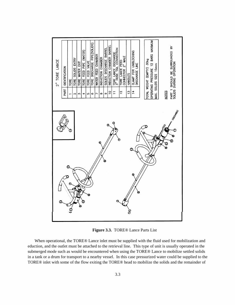
Figure 3.3. TORE® Lance Parts List
When operational, the TORE® Lance inlet must be supplied with the fluid used for mobilization and
eduction, and the outlet must be attached to the retrieval line. This type of unit is usually operated in the
submerged mode such as would be encountered when using the TORE® Lance to mobilize settled solids
in a tank or a drum for transport to a nearby vessel. In this case pressurized water could be supplied to the
TORE® inlet with some of the flow exiting the TORE® head to mobilize the solids and the remainder of
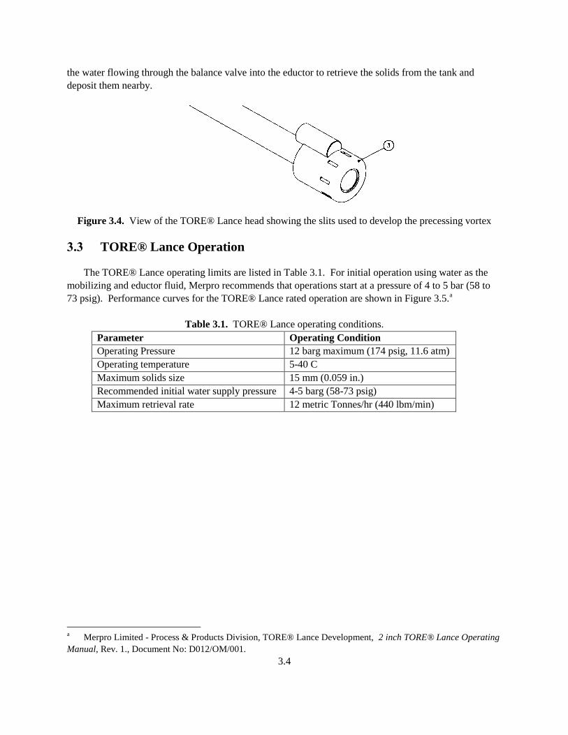
3.4
the water flowing through the balance valve into the eductor to retrieve the solids from the tank and
deposit them nearby.
Figure 3.4. View of the TORE® Lance head showing the slits used to develop the precessing vortex
3.3 TORE® Lance Operation
The TORE® Lance operating limits are listed in Table 3.1. For initial operation using water as the
mobilizing and eductor fluid, Merpro recommends that operations start at a pressure of 4 to 5 bar (58 to
73 psig). Performance curves for the TORE® Lance rated operation are shown in Figure 3.5.a
Table 3.1. TORE® Lance operating conditions.
Parameter Operating Condition
Operating Pressure 12 barg maximum (174 psig, 11.6 atm)
Operating temperature 5-40 C
Maximum solids size 15 mm (0.059 in.)
Recommended initial water supply pressure 4-5 barg (58-73 psig)
Maximum retrieval rate 12 metric Tonnes/hr (440 lbm/min)
a Merpro Limited - Process & Products Division, TORE® Lance Development, 2 inch TORE® Lance Operating
Manual, Rev. 1., Document No: D012/OM/001.
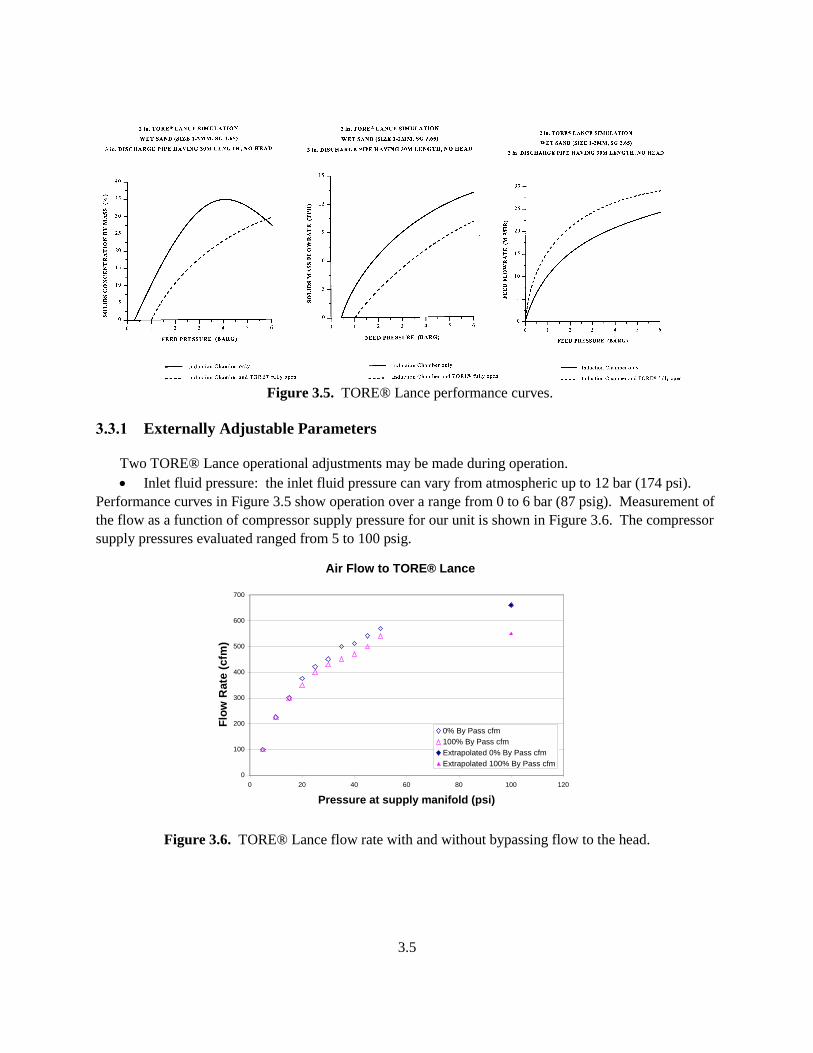
3.5
Figure 3.5. TORE® Lance performance curves.
3.3.1 Externally Adjustable Parameters
Two TORE® Lance operational adjustments may be made during operation.
Inlet fluid pressure: the inlet fluid pressure can vary from atmospheric up to 12 bar (174 psi).
Performance curves in Figure 3.5 show operation over a range from 0 to 6 bar (87 psig). Measurement of
the flow as a function of compressor supply pressure for our unit is shown in Figure 3.6. The compressor
supply pressures evaluated ranged from 5 to 100 psig.
Figure 3.6. TORE® Lance flow rate with and without bypassing flow to the head.
Air Flow to TORE® Lance
0
100
200
300
400
500
600
700
0 20 40 60 80 100 120
Pressure at supply manifold (psi)
Flo
w R
ate
(cfm
)
0% By Pass cfm
100% By Pass cfm
Extrapolated 0% By Pass cfm
Extrapolated 100% By Pass cfm
3.6
Flow split between the eductor and the TORE® Lance head.
This flow split is adjusted using the manually operated bypass flow balance valve located on the manifold
near the center of the TORE® Lance. The internal components of this valve are shown in Figure 3.7.
Figure 3.7. View inside the flow control manifold showing the connection between the upper
and lower ceramic pieces that line the inside of the eductor.
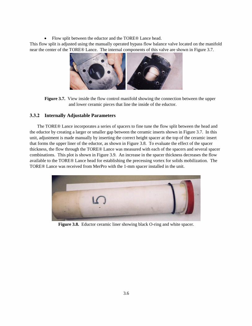
3.3.2 Internally Adjustable Parameters
The TORE® Lance incorporates a series of spacers to fine tune the flow split between the head and
the eductor by creating a larger or smaller gap between the ceramic inserts shown in Figure 3.7. In this
unit, adjustment is made manually by inserting the correct height spacer at the top of the ceramic insert
that forms the upper liner of the eductor, as shown in Figure 3.8. To evaluate the effect of the spacer
thickness, the flow through the TORE® Lance was measured with each of the spacers and several spacer
combinations. This plot is shown in Figure 3.9. An increase in the spacer thickness decreases the flow
available to the TORE® Lance head for establishing the precessing vortex for solids mobilization. The
TORE® Lance was received from MerPro with the 1-mm spacer installed in the unit.
Figure 3.8. Eductor ceramic liner showing black O-ring and white spacer.
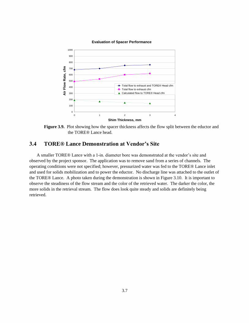
3.7
Figure 3.9. Plot showing how the spacer thickness affects the flow split between the eductor and
the TORE® Lance head.
3.4 TORE® Lance Demonstration at Vendor’s Site
A smaller TORE® Lance with a 1-in. diameter bore was demonstrated at the vendor’s site and
observed by the project sponsor. The application was to remove sand from a series of channels. The
operating conditions were not specified; however, pressurized water was fed to the TORE® Lance inlet
and used for solids mobilization and to power the eductor. No discharge line was attached to the outlet of
the TORE® Lance. A photo taken during the demonstration is shown in Figure 3.10. It is important to
observe the steadiness of the flow stream and the color of the retrieved water. The darker the color, the
more solids in the retrieval stream. The flow does look quite steady and solids are definitely being
retrieved.
Evaluation of Spacer Performance
0
100
200
300
400
500
600
700
800
900
1000
0 1 2 3 4
Shim Thickness, mm
Air
Flo
w R
ate
, c
fm
Total flow to exhaust and TORE® Head cfm
Total flow to exhaust cfm
Calculated flow to TORE® Head cfm
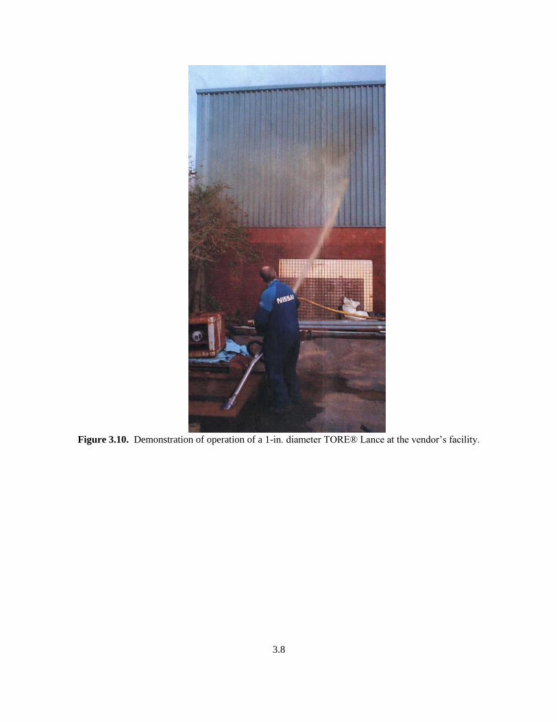
3.8
Figure 3.10. Demonstration of operation of a 1-in. diameter TORE® Lance at the vendor’s facility.

4.1
4.0 Experimental Configuration
To evaluate the performance of the TORE® Lance, a series of small-scale tests were conducted to
investigate different system configurations, operating configurations, and the ability to mobilize and
retrieve different simulants. The test facility, instrumentation, and test matrix used during these tests are
described in this section. In addition, the details of the simulant selection and the simulant physical
properties are presented.
4.1 Test Facility
The TORE® Lance evaluation was conducted at Hanford in the 336 Building Fluid Dynamics
Laboratory using selected equipment, shown in Figure 1. This figure shows equipment, process
connections, and instrumentation.
Figure 4.1. TORE® Lance test configuration
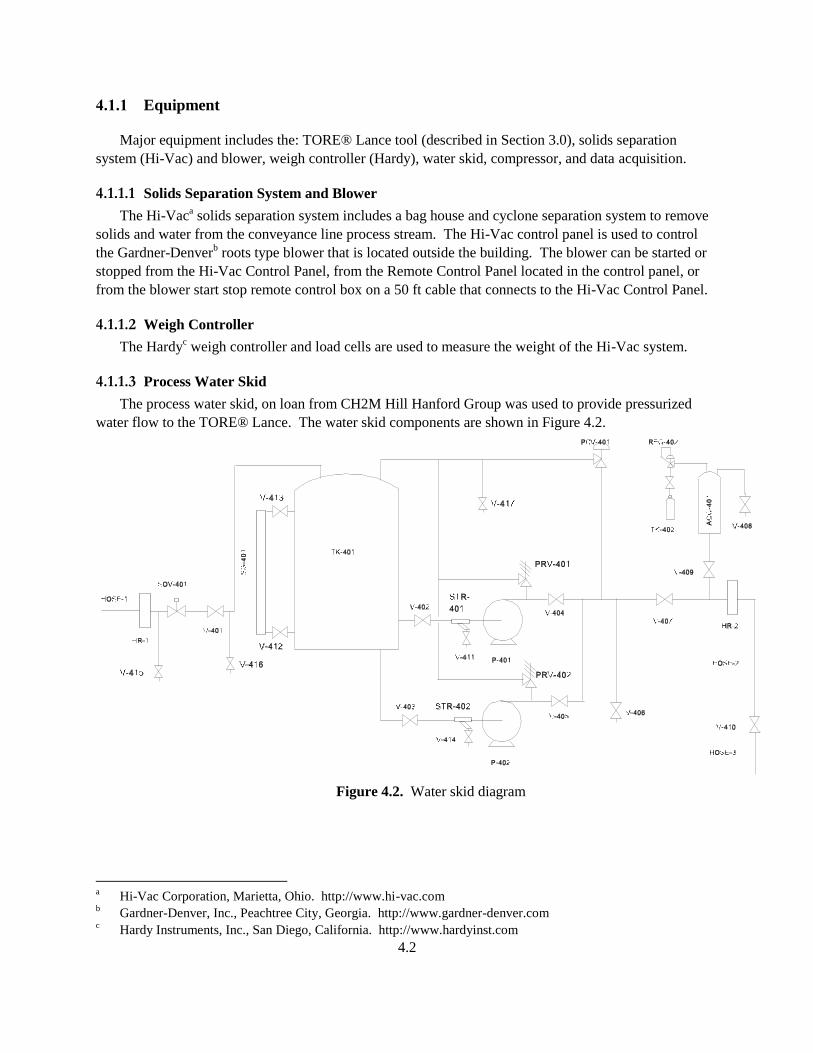
4.2
4.1.1 Equipment
Major equipment includes the: TORE® Lance tool (described in Section 3.0), solids separation
system (Hi-Vac) and blower, weigh controller (Hardy), water skid, compressor, and data acquisition.
4.1.1.1 Solids Separation System and Blower
The Hi-Vaca solids separation system includes a bag house and cyclone separation system to remove
solids and water from the conveyance line process stream. The Hi-Vac control panel is used to control
the Gardner-Denverb roots type blower that is located outside the building. The blower can be started or
stopped from the Hi-Vac Control Panel, from the Remote Control Panel located in the control panel, or
from the blower start stop remote control box on a 50 ft cable that connects to the Hi-Vac Control Panel.
4.1.1.2 Weigh Controller
The Hardyc weigh controller and load cells are used to measure the weight of the Hi-Vac system.
4.1.1.3 Process Water Skid
The process water skid, on loan from CH2M Hill Hanford Group was used to provide pressurized
water flow to the TORE® Lance. The water skid components are shown in Figure 4.2.
Figure 4.2. Water skid diagram
a Hi-Vac Corporation, Marietta, Ohio. http://www.hi-vac.com
b Gardner-Denver, Inc., Peachtree City, Georgia. http://www.gardner-denver.com
c Hardy Instruments, Inc., San Diego, California. http://www.hardyinst.com
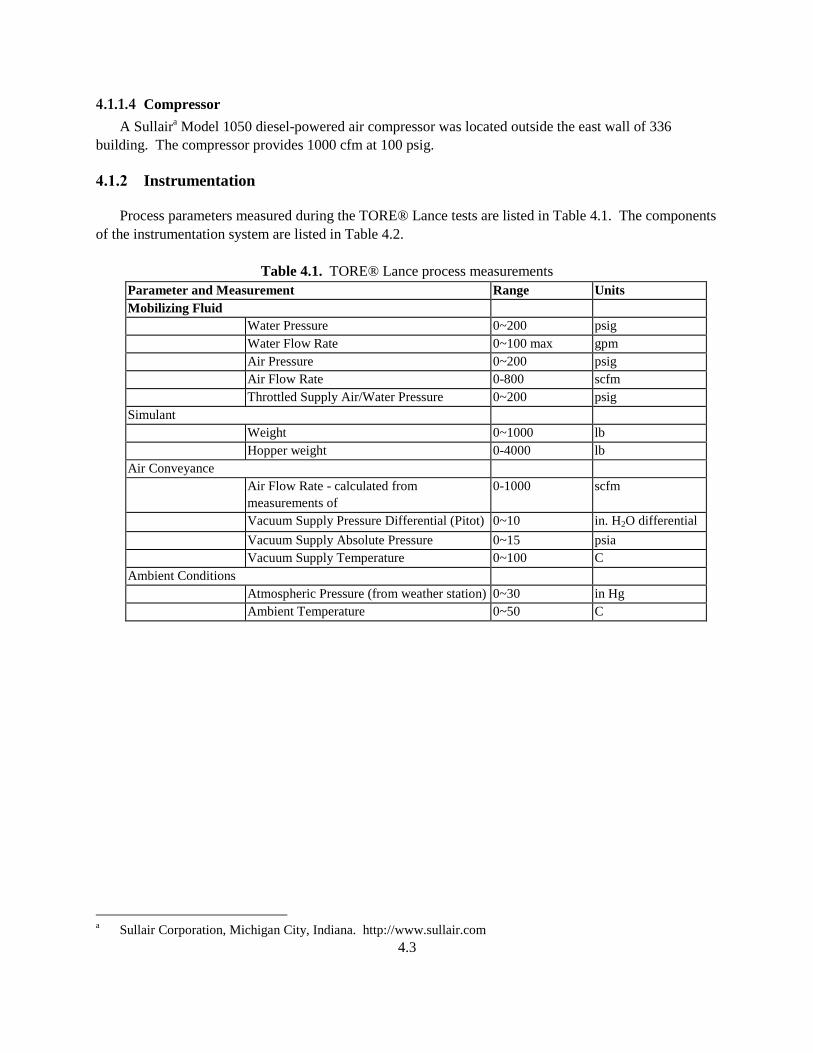
4.3
4.1.1.4 Compressor
A Sullaira Model 1050 diesel-powered air compressor was located outside the east wall of 336
building. The compressor provides 1000 cfm at 100 psig.
4.1.2 Instrumentation
Process parameters measured during the TORE® Lance tests are listed in Table 4.1. The components
of the instrumentation system are listed in Table 4.2.
Table 4.1. TORE® Lance process measurements
Parameter and Measurement Range Units
Mobilizing Fluid
Water Pressure 0~200 psig
Water Flow Rate 0~100 max gpm
Air Pressure 0~200 psig
Air Flow Rate 0-800 scfm
Throttled Supply Air/Water Pressure 0~200 psig
Simulant
Weight 0~1000 lb
Hopper weight 0-4000 lb
Air Conveyance
Air Flow Rate - calculated from
measurements of
0-1000 scfm
Vacuum Supply Pressure Differential (Pitot) 0~10 in. H2O differential
Vacuum Supply Absolute Pressure 0~15 psia
Vacuum Supply Temperature 0~100 C
Ambient Conditions
Atmospheric Pressure (from weather station) 0~30 in Hg
Ambient Temperature 0~50 C
a Sullair Corporation, Michigan City, Indiana. http://www.sullair.com
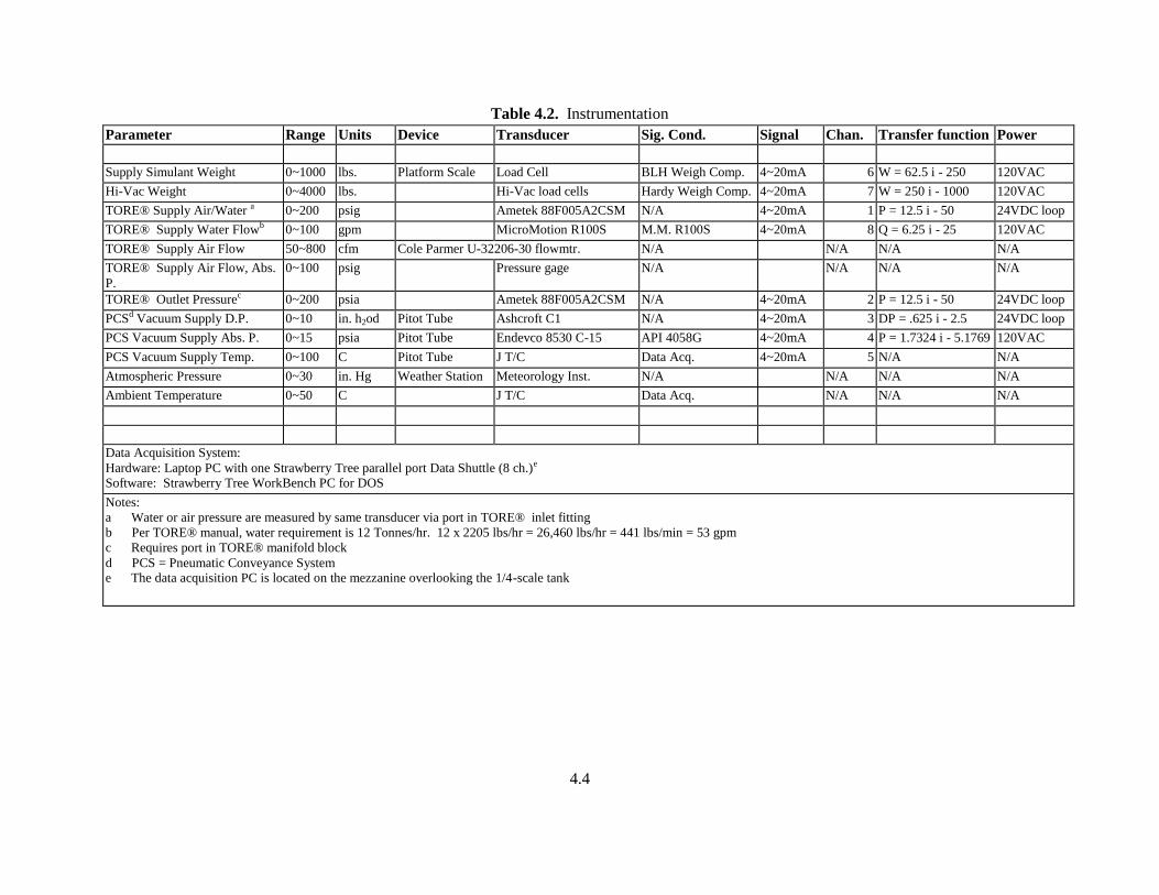
4.4
Table 4.2. Instrumentation
Parameter Range Units Device Transducer Sig. Cond. Signal Chan. Transfer function Power
Supply Simulant Weight 0~1000 lbs. Platform Scale Load Cell BLH Weigh Comp. 4~20mA 6 W = 62.5 i - 250 120VAC
Hi-Vac Weight 0~4000 lbs. Hi-Vac load cells Hardy Weigh Comp. 4~20mA 7 W = 250 i - 1000 120VAC
TORE® Supply Air/Water a 0~200 psig Ametek 88F005A2CSM N/A 4~20mA 1 P = 12.5 i - 50 24VDC loop
TORE® Supply Water Flowb 0~100 gpm MicroMotion R100S M.M. R100S 4~20mA 8 Q = 6.25 i - 25 120VAC
TORE® Supply Air Flow 50~800 cfm Cole Parmer U-32206-30 flowmtr. N/A N/A N/A N/A
TORE® Supply Air Flow, Abs.
P.
0~100 psig Pressure gage N/A N/A N/A N/A
TORE® Outlet Pressurec 0~200 psia Ametek 88F005A2CSM N/A 4~20mA 2 P = 12.5 i - 50 24VDC loop
PCSd Vacuum Supply D.P. 0~10 in. h2od Pitot Tube Ashcroft C1 N/A 4~20mA 3 DP = .625 i - 2.5 24VDC loop
PCS Vacuum Supply Abs. P. 0~15 psia Pitot Tube Endevco 8530 C-15 API 4058G 4~20mA 4 P = 1.7324 i - 5.1769 120VAC
PCS Vacuum Supply Temp. 0~100 C Pitot Tube J T/C Data Acq. 4~20mA 5 N/A N/A
Atmospheric Pressure 0~30 in. Hg Weather Station Meteorology Inst. N/A N/A N/A N/A
Ambient Temperature 0~50 C J T/C Data Acq. N/A N/A N/A
Data Acquisition System:
Hardware: Laptop PC with one Strawberry Tree parallel port Data Shuttle (8 ch.)e
Software: Strawberry Tree WorkBench PC for DOS
Notes:
a Water or air pressure are measured by same transducer via port in TORE® inlet fitting
b Per TORE® manual, water requirement is 12 Tonnes/hr. 12 x 2205 lbs/hr = 26,460 lbs/hr = 441 lbs/min = 53 gpm
c Requires port in TORE® manifold block
d PCS = Pneumatic Conveyance System e The data acquisition PC is located on the mezzanine overlooking the 1/4-scale tank

4.5
4.2 Simulant Selection and Characterization
The simulant selection took into account
Anticipated waste types expected to be found in tank 241-C-104
Guidance from Merpro literature regarding types of solids transported
Recommendations for the MRS system qualification.
4.2.1 241-C-104 Waste Properties
Analysis of existing physical and chemical property data of the waste in tank 241-C-104 provided
guidance for simulant selection. Property values of slurried tank waste during retrieval include:
Liquid density - 1.1 to 1.4 kg/l
Liquid viscosity - 10 to 100 cP
Slurry temperature 80 to 120 F
Solids density 2.5 to 3.0 kg/l
In tank operating temperature 20.8 C (80 F) to 45.7 C (100 F).
Waste property data from Estey (2001) recommends:
Using a conservative solids density of 3.00 kg/l, the bulk physical composition of tank C-104
sludge is about 72% by volume liquid and 28% by volume solids with a bulk density of 1.67 kg/l
and a liquid phase density of 1.19 kg/l.
Analyzed particle sizes ranged from 5 to 6350 m. 6350 m represents the largest minimal
dimension of a particle that could pass through a 1/4 in. filter screen. Laboratory analysis
suggests that the vast majority of particles derived from tank 241-C-104 sludge have mean
diameters < 275 m in diameter.
Jewett et al. (2002) recommended values for three waste properties, particle size distribution, particle
density, and slurry viscosity, to be used for planned waste feed delivery system analysis. The particle
size distributions were obtained from analysis of samples from 7 of 10 Phase 1 high level waste feed
tanks. The particle size data show
7.5 m + 4.2 m mean
the one sided 95/95 tolerance limit value for the 50th percentile is 22 m. This means that with 95
percent confidence at least 95 percent of the tanks will have a median particle size no larger than
22 m.
the 95% UL (upper limit to a one-sided 95 percent confidence limit on the mean) is 11 m. The
95% UL means that we are 95% confident that the true mean for all the wastes will be less than
the computed value.
The average of the dry-basis densities of the solids in eight high level waste tanks is calculated to be
2.9 kg/l. This is a conservative value because the value ignores the beneficial effect of agglomeration,
which probably reduces the effective density of the solids to a value of around 2.2 kg/l. The solids
density is the least known waste property required for pipeline transfer assessment. A curve fit that is a
function of the volume fraction is provided for density. The report (Jewett et al. 2002) also states that
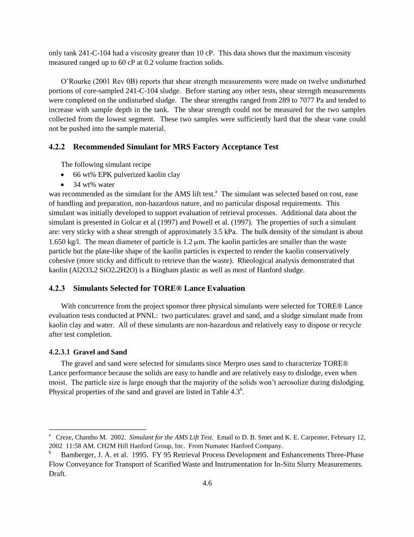
4.6
only tank 241-C-104 had a viscosity greater than 10 cP. This data shows that the maximum viscosity
measured ranged up to 60 cP at 0.2 volume fraction solids.
O’Rourke (2001 Rev 0B) reports that shear strength measurements were made on twelve undisturbed
portions of core-sampled 241-C-104 sludge. Before starting any other tests, shear strength measurements
were completed on the undisturbed sludge. The shear strengths ranged from 289 to 7077 Pa and tended to
increase with sample depth in the tank. The shear strength could not be measured for the two samples
collected from the lowest segment. These two samples were sufficiently hard that the shear vane could
not be pushed into the sample material.
4.2.2 Recommended Simulant for MRS Factory Acceptance Test
The following simulant recipe
66 wt% EPK pulverized kaolin clay
34 wt% water
was recommended as the simulant for the AMS lift test.a The simulant was selected based on cost, ease
of handling and preparation, non-hazardous nature, and no particular disposal requirements. This
simulant was initially developed to support evaluation of retrieval processes. Additional data about the
simulant is presented in Golcar et al (1997) and Powell et al. (1997). The properties of such a simulant
are: very sticky with a shear strength of approximately 3.5 kPa. The bulk density of the simulant is about
1.650 kg/l. The mean diameter of particle is 1.2 m. The kaolin particles are smaller than the waste
particle but the plate-like shape of the kaolin particles is expected to render the kaolin conservatively
cohesive (more sticky and difficult to retrieve than the waste). Rheological analysis demonstrated that
kaolin (Al2O3.2 SiO2.2H2O) is a Bingham plastic as well as most of Hanford sludge.
4.2.3 Simulants Selected for TORE® Lance Evaluation
With concurrence from the project sponsor three physical simulants were selected for TORE® Lance
evaluation tests conducted at PNNL: two particulates: gravel and sand, and a sludge simulant made from
kaolin clay and water. All of these simulants are non-hazardous and relatively easy to dispose or recycle
after test completion.
4.2.3.1 Gravel and Sand
The gravel and sand were selected for simulants since Merpro uses sand to characterize TORE®
Lance performance because the solids are easy to handle and are relatively easy to dislodge, even when
moist. The particle size is large enough that the majority of the solids won’t aerosolize during dislodging.
Physical properties of the sand and gravel are listed in Table 4.3b.
a Creze, Chantho M. 2002. Simulant for the AMS Lift Test. Email to D. B. Smet and K. E. Carpenter, February 12,
2002 11:58 AM. CH2M Hill Hanford Group, Inc. From Numatec Hanford Company. b Bamberger, J. A. et al. 1995. FY 95 Retrieval Process Development and Enhancements Three-Phase
Flow Conveyance for Transport of Scarified Waste and Instrumentation for In-Situ Slurry Measurements.
Draft.
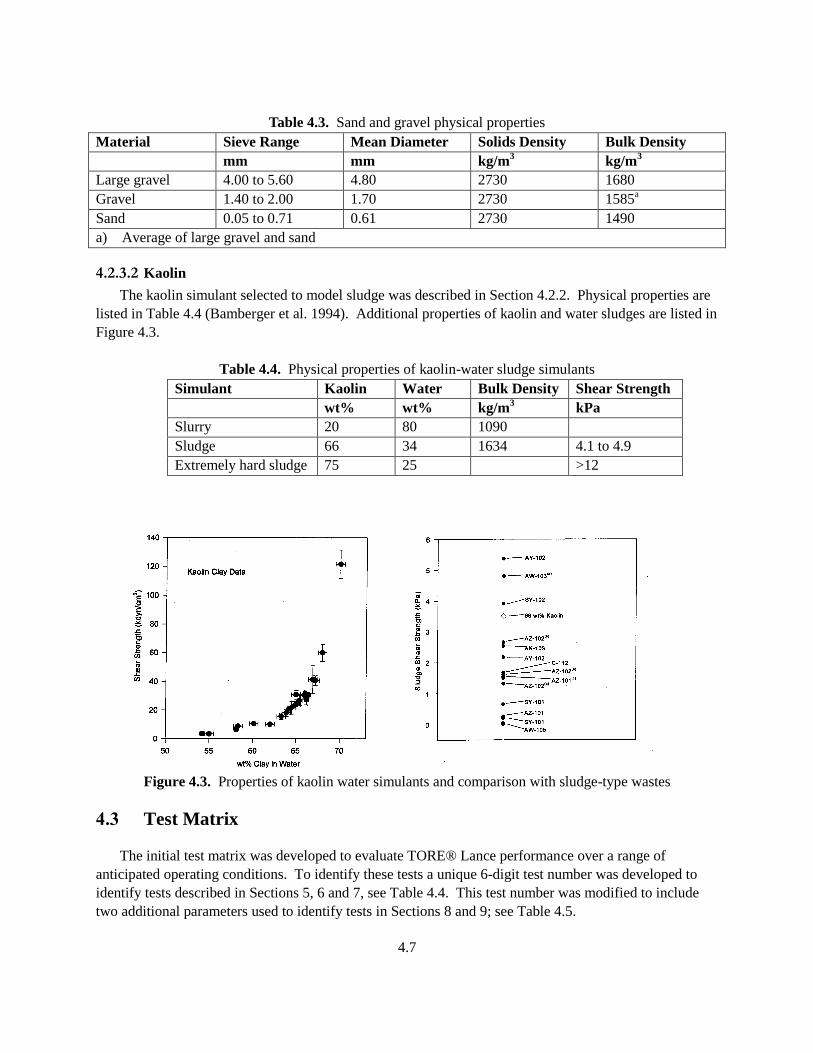
4.7
Table 4.3. Sand and gravel physical properties
Material Sieve Range Mean Diameter Solids Density Bulk Density
mm mm kg/m3
kg/m3
Large gravel 4.00 to 5.60 4.80 2730 1680
Gravel 1.40 to 2.00 1.70 2730 1585a
Sand 0.05 to 0.71 0.61 2730 1490
a) Average of large gravel and sand
4.2.3.2 Kaolin
The kaolin simulant selected to model sludge was described in Section 4.2.2. Physical properties are
listed in Table 4.4 (Bamberger et al. 1994). Additional properties of kaolin and water sludges are listed in
Figure 4.3.
Table 4.4. Physical properties of kaolin-water sludge simulants
Simulant Kaolin Water Bulk Density Shear Strength
wt% wt% kg/m3
kPa
Slurry 20 80 1090
Sludge 66 34 1634 4.1 to 4.9
Extremely hard sludge 75 25 >12
Figure 4.3. Properties of kaolin water simulants and comparison with sludge-type wastes
4.3 Test Matrix
The initial test matrix was developed to evaluate TORE® Lance performance over a range of
anticipated operating conditions. To identify these tests a unique 6-digit test number was developed to
identify tests described in Sections 5, 6 and 7, see Table 4.4. This test number was modified to include
two additional parameters used to identify tests in Sections 8 and 9; see Table 4.5.
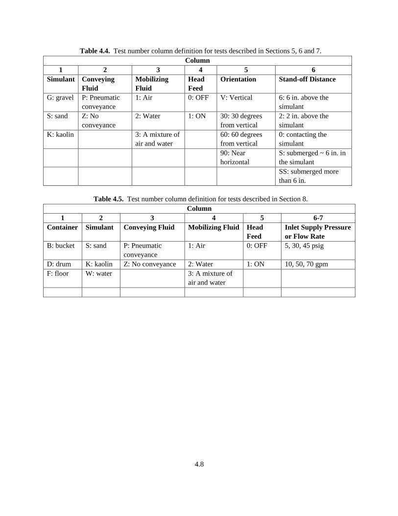
4.8
Table 4.4. Test number column definition for tests described in Sections 5, 6 and 7.
Column
1 2 3 4 5 6
Simulant Conveying
Fluid
Mobilizing
Fluid
Head
Feed
Orientation Stand-off Distance
G: gravel P: Pneumatic
conveyance
1: Air 0: OFF V: Vertical 6: 6 in. above the
simulant
S: sand Z: No
conveyance
2: Water 1: ON 30: 30 degrees
from vertical
2: 2 in. above the
simulant
K: kaolin 3: A mixture of
air and water
60: 60 degrees
from vertical
0: contacting the
simulant
90: Near
horizontal
S: submerged ~ 6 in. in
the simulant
SS: submerged more
than 6 in.
Table 4.5. Test number column definition for tests described in Section 8.
Column
1 2 3 4 5 6-7
Container Simulant Conveying Fluid Mobilizing Fluid Head
Feed
Inlet Supply Pressure
or Flow Rate
B: bucket S: sand P: Pneumatic
conveyance
1: Air 0: OFF 5, 30, 45 psig
D: drum K: kaolin Z: No conveyance 2: Water 1: ON 10, 50, 70 gpm
F: floor W: water 3: A mixture of
air and water
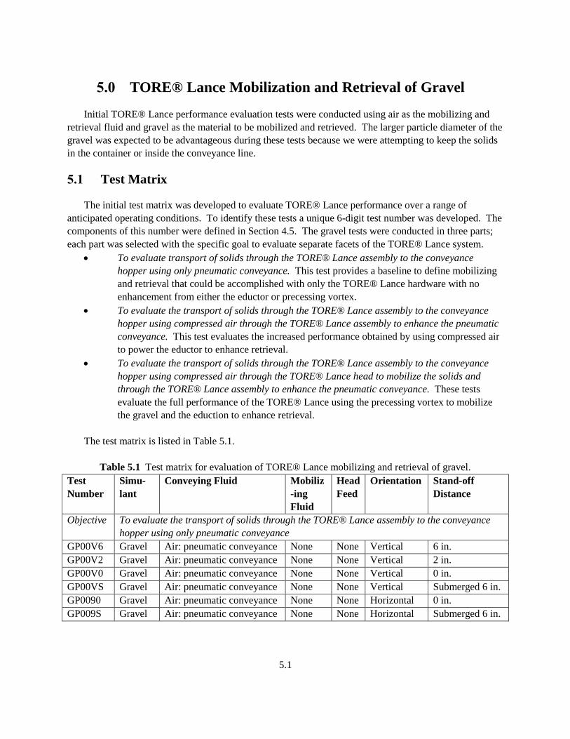
5.1
5.0 TORE® Lance Mobilization and Retrieval of Gravel
Initial TORE® Lance performance evaluation tests were conducted using air as the mobilizing and
retrieval fluid and gravel as the material to be mobilized and retrieved. The larger particle diameter of the
gravel was expected to be advantageous during these tests because we were attempting to keep the solids
in the container or inside the conveyance line.
5.1 Test Matrix
The initial test matrix was developed to evaluate TORE® Lance performance over a range of
anticipated operating conditions. To identify these tests a unique 6-digit test number was developed. The
components of this number were defined in Section 4.5. The gravel tests were conducted in three parts;
each part was selected with the specific goal to evaluate separate facets of the TORE® Lance system.
To evaluate transport of solids through the TORE® Lance assembly to the conveyance
hopper using only pneumatic conveyance. This test provides a baseline to define mobilizing
and retrieval that could be accomplished with only the TORE® Lance hardware with no
enhancement from either the eductor or precessing vortex.
To evaluate the transport of solids through the TORE® Lance assembly to the conveyance
hopper using compressed air through the TORE® Lance assembly to enhance the pneumatic
conveyance. This test evaluates the increased performance obtained by using compressed air
to power the eductor to enhance retrieval.
To evaluate the transport of solids through the TORE® Lance assembly to the conveyance
hopper using compressed air through the TORE® Lance head to mobilize the solids and
through the TORE® Lance assembly to enhance the pneumatic conveyance. These tests
evaluate the full performance of the TORE® Lance using the precessing vortex to mobilize
the gravel and the eduction to enhance retrieval.
The test matrix is listed in Table 5.1.
Table 5.1 Test matrix for evaluation of TORE® Lance mobilizing and retrieval of gravel.
Test
Number
Simu-
lant
Conveying Fluid Mobiliz
-ing
Fluid
Head
Feed
Orientation Stand-off
Distance
Objective To evaluate the transport of solids through the TORE® Lance assembly to the conveyance
hopper using only pneumatic conveyance
GP00V6 Gravel Air: pneumatic conveyance None None Vertical 6 in.
GP00V2 Gravel Air: pneumatic conveyance None None Vertical 2 in.
GP00V0 Gravel Air: pneumatic conveyance None None Vertical 0 in.
GP00VS Gravel Air: pneumatic conveyance None None Vertical Submerged 6 in.
GP0090 Gravel Air: pneumatic conveyance None None Horizontal 0 in.
GP009S Gravel Air: pneumatic conveyance None None Horizontal Submerged 6 in.
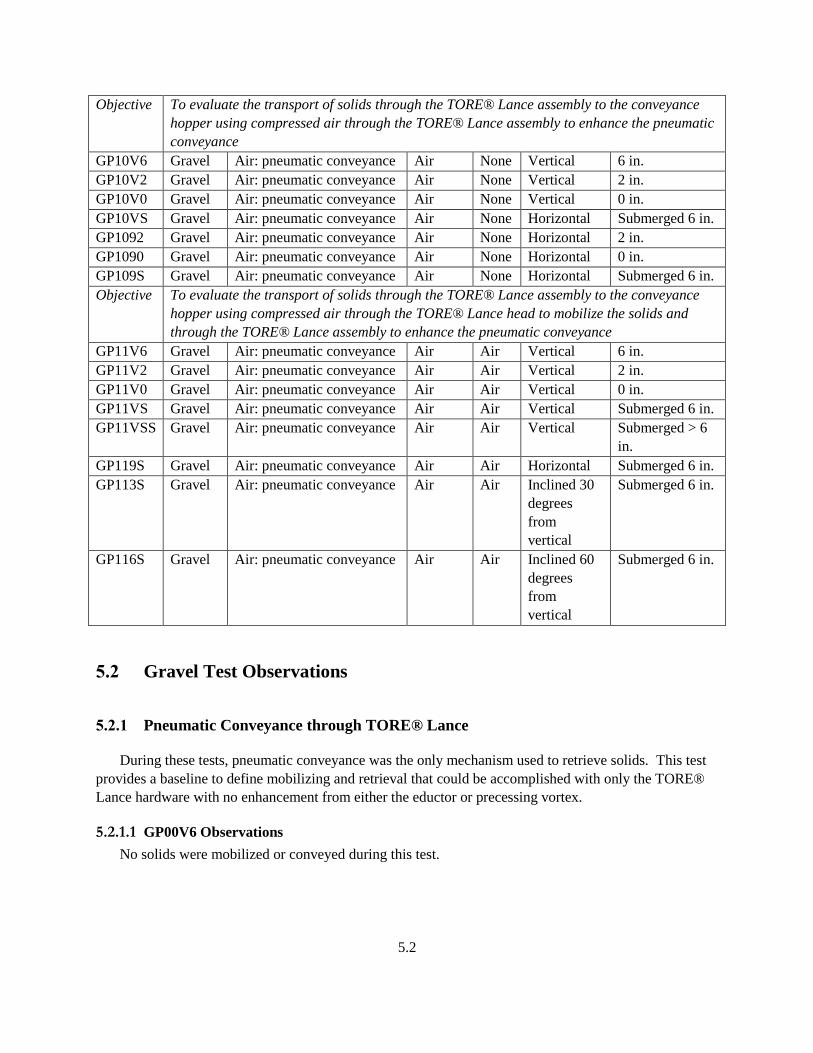
5.2
Objective To evaluate the transport of solids through the TORE® Lance assembly to the conveyance
hopper using compressed air through the TORE® Lance assembly to enhance the pneumatic
conveyance
GP10V6 Gravel Air: pneumatic conveyance Air None Vertical 6 in.
GP10V2 Gravel Air: pneumatic conveyance Air None Vertical 2 in.
GP10V0 Gravel Air: pneumatic conveyance Air None Vertical 0 in.
GP10VS Gravel Air: pneumatic conveyance Air None Horizontal Submerged 6 in.
GP1092 Gravel Air: pneumatic conveyance Air None Horizontal 2 in.
GP1090 Gravel Air: pneumatic conveyance Air None Horizontal 0 in.
GP109S Gravel Air: pneumatic conveyance Air None Horizontal Submerged 6 in.
Objective To evaluate the transport of solids through the TORE® Lance assembly to the conveyance
hopper using compressed air through the TORE® Lance head to mobilize the solids and
through the TORE® Lance assembly to enhance the pneumatic conveyance
GP11V6 Gravel Air: pneumatic conveyance Air Air Vertical 6 in.
GP11V2 Gravel Air: pneumatic conveyance Air Air Vertical 2 in.
GP11V0 Gravel Air: pneumatic conveyance Air Air Vertical 0 in.
GP11VS Gravel Air: pneumatic conveyance Air Air Vertical Submerged 6 in.
GP11VSS Gravel Air: pneumatic conveyance Air Air Vertical Submerged > 6
in.
GP119S Gravel Air: pneumatic conveyance Air Air Horizontal Submerged 6 in.
GP113S Gravel Air: pneumatic conveyance Air Air Inclined 30
degrees
from
vertical
Submerged 6 in.
GP116S Gravel Air: pneumatic conveyance Air Air Inclined 60
degrees
from
vertical
Submerged 6 in.
5.2 Gravel Test Observations
5.2.1 Pneumatic Conveyance through TORE® Lance
During these tests, pneumatic conveyance was the only mechanism used to retrieve solids. This test
provides a baseline to define mobilizing and retrieval that could be accomplished with only the TORE®
Lance hardware with no enhancement from either the eductor or precessing vortex.
5.2.1.1 GP00V6 Observations
No solids were mobilized or conveyed during this test.
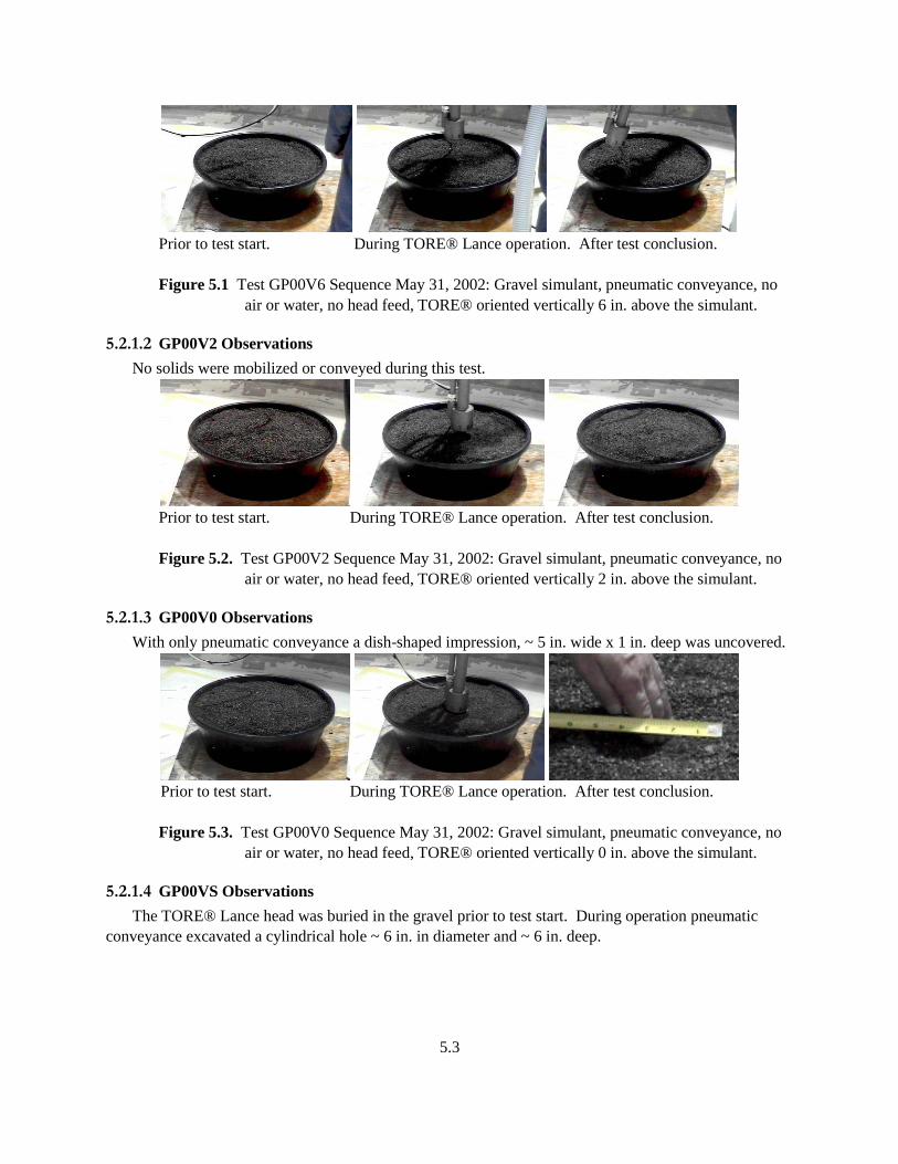
5.3
Prior to test start. During TORE® Lance operation. After test conclusion.
Figure 5.1 Test GP00V6 Sequence May 31, 2002: Gravel simulant, pneumatic conveyance, no
air or water, no head feed, TORE® oriented vertically 6 in. above the simulant.
5.2.1.2 GP00V2 Observations
No solids were mobilized or conveyed during this test.
Prior to test start. During TORE® Lance operation. After test conclusion.
Figure 5.2. Test GP00V2 Sequence May 31, 2002: Gravel simulant, pneumatic conveyance, no
air or water, no head feed, TORE® oriented vertically 2 in. above the simulant.
5.2.1.3 GP00V0 Observations
With only pneumatic conveyance a dish-shaped impression, ~ 5 in. wide x 1 in. deep was uncovered.
Prior to test start. During TORE® Lance operation. After test conclusion.
Figure 5.3. Test GP00V0 Sequence May 31, 2002: Gravel simulant, pneumatic conveyance, no
air or water, no head feed, TORE® oriented vertically 0 in. above the simulant.
5.2.1.4 GP00VS Observations
The TORE® Lance head was buried in the gravel prior to test start. During operation pneumatic
conveyance excavated a cylindrical hole ~ 6 in. in diameter and ~ 6 in. deep.
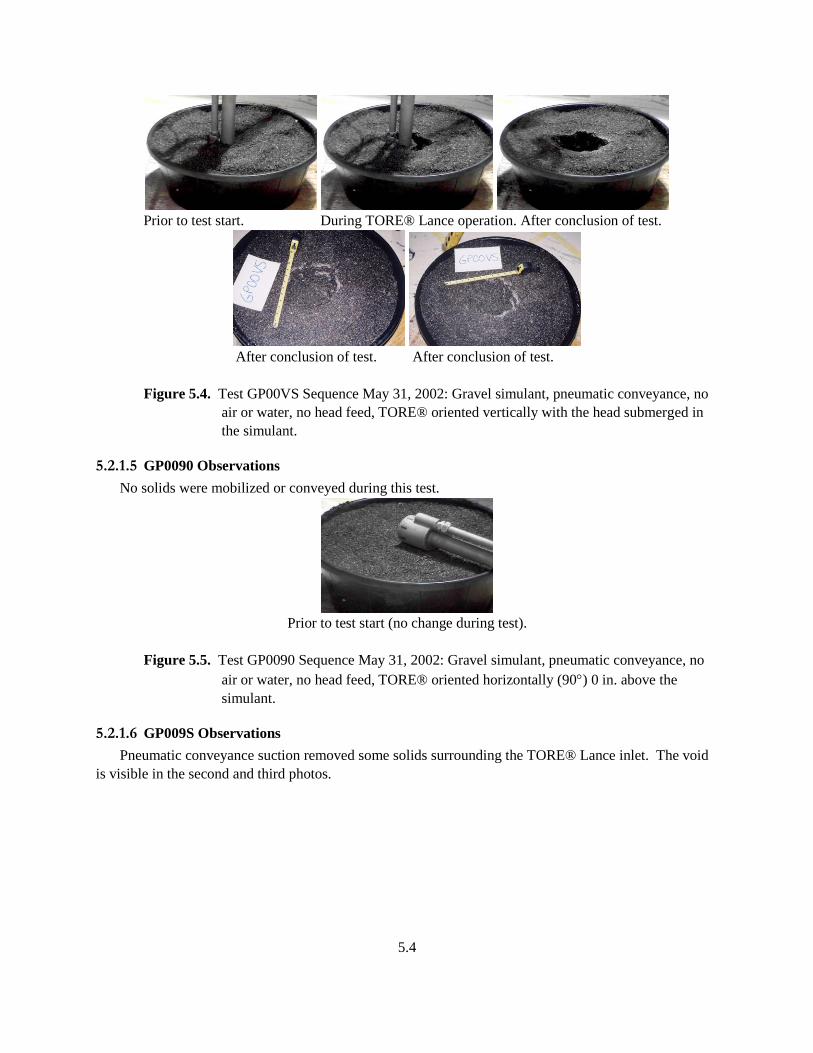
5.4
Prior to test start. During TORE® Lance operation. After conclusion of test.
After conclusion of test. After conclusion of test.
Figure 5.4. Test GP00VS Sequence May 31, 2002: Gravel simulant, pneumatic conveyance, no
air or water, no head feed, TORE® oriented vertically with the head submerged in
the simulant.
5.2.1.5 GP0090 Observations
No solids were mobilized or conveyed during this test.
Prior to test start (no change during test).
Figure 5.5. Test GP0090 Sequence May 31, 2002: Gravel simulant, pneumatic conveyance, no
air or water, no head feed, TORE® oriented horizontally (90) 0 in. above the
simulant.
5.2.1.6 GP009S Observations
Pneumatic conveyance suction removed some solids surrounding the TORE® Lance inlet. The void
is visible in the second and third photos.
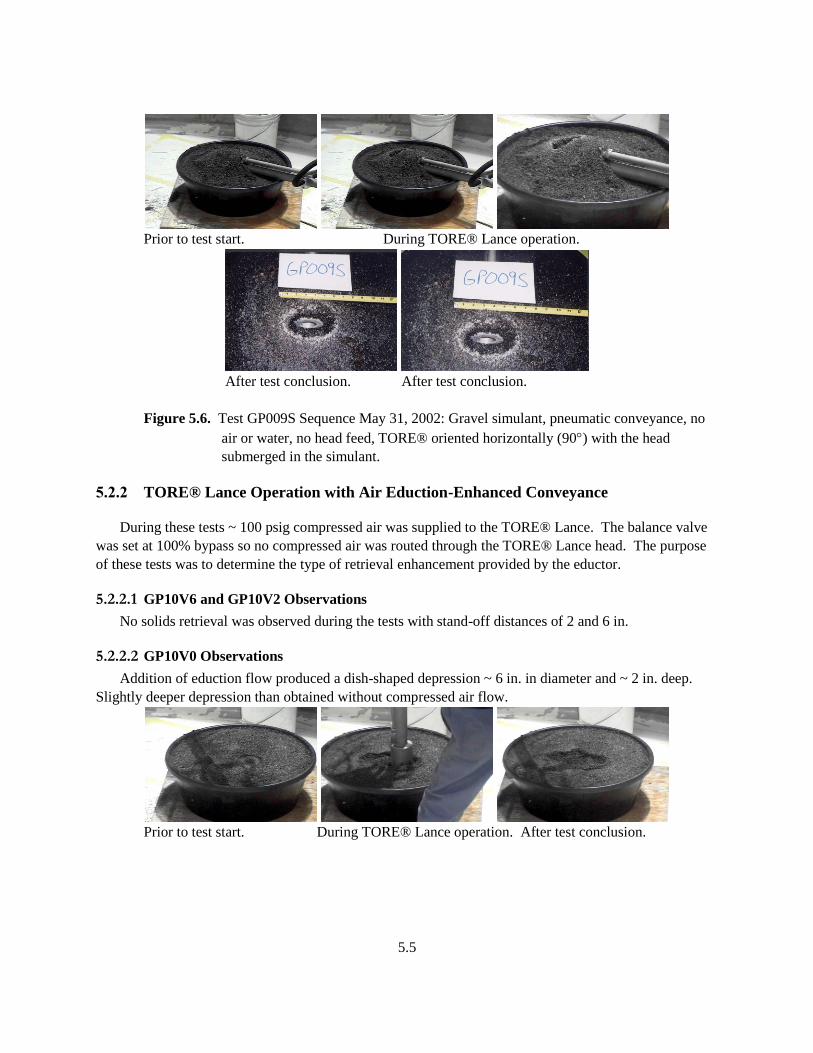
5.5
Prior to test start. During TORE® Lance operation.
After test conclusion. After test conclusion.
Figure 5.6. Test GP009S Sequence May 31, 2002: Gravel simulant, pneumatic conveyance, no
air or water, no head feed, TORE® oriented horizontally (90) with the head
submerged in the simulant.
5.2.2 TORE® Lance Operation with Air Eduction-Enhanced Conveyance
During these tests ~ 100 psig compressed air was supplied to the TORE® Lance. The balance valve
was set at 100% bypass so no compressed air was routed through the TORE® Lance head. The purpose
of these tests was to determine the type of retrieval enhancement provided by the eductor.
5.2.2.1 GP10V6 and GP10V2 Observations
No solids retrieval was observed during the tests with stand-off distances of 2 and 6 in.
5.2.2.2 GP10V0 Observations
Addition of eduction flow produced a dish-shaped depression ~ 6 in. in diameter and ~ 2 in. deep.
Slightly deeper depression than obtained without compressed air flow.
Prior to test start. During TORE® Lance operation. After test conclusion.
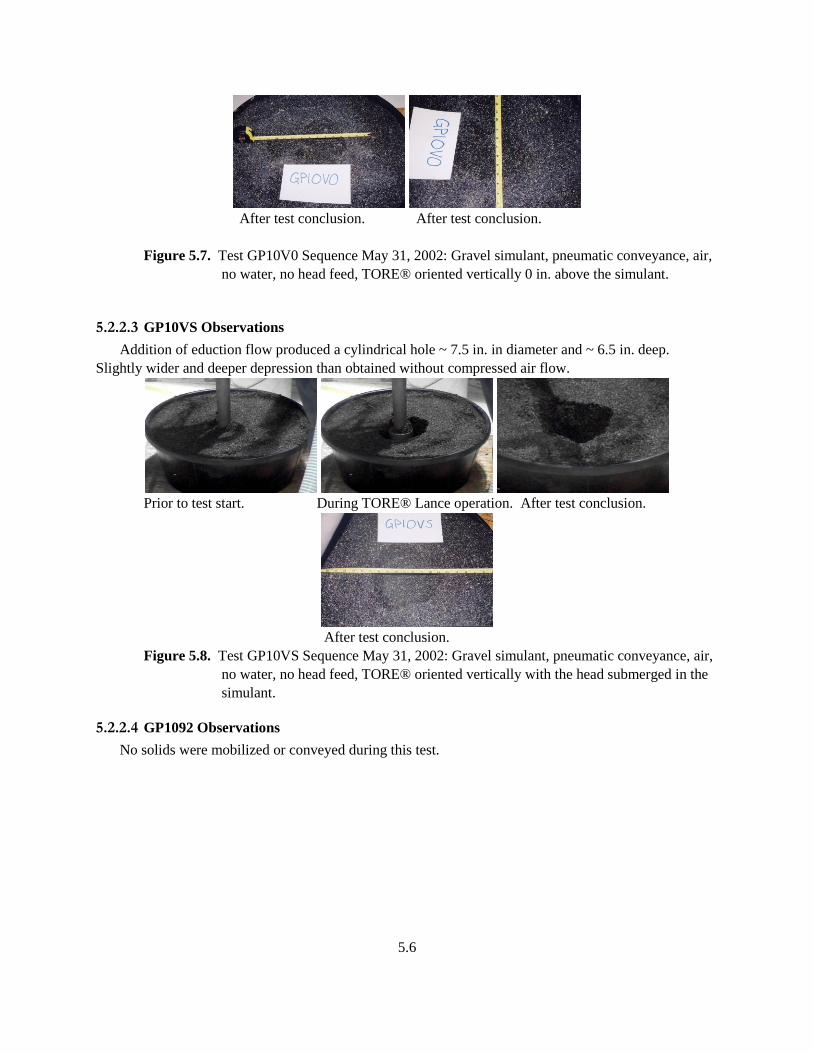
5.6
After test conclusion. After test conclusion.
Figure 5.7. Test GP10V0 Sequence May 31, 2002: Gravel simulant, pneumatic conveyance, air,
no water, no head feed, TORE® oriented vertically 0 in. above the simulant.
5.2.2.3 GP10VS Observations
Addition of eduction flow produced a cylindrical hole ~ 7.5 in. in diameter and ~ 6.5 in. deep.
Slightly wider and deeper depression than obtained without compressed air flow.
Prior to test start. During TORE® Lance operation. After test conclusion.
After test conclusion.
Figure 5.8. Test GP10VS Sequence May 31, 2002: Gravel simulant, pneumatic conveyance, air,
no water, no head feed, TORE® oriented vertically with the head submerged in the
simulant.
5.2.2.4 GP1092 Observations
No solids were mobilized or conveyed during this test.
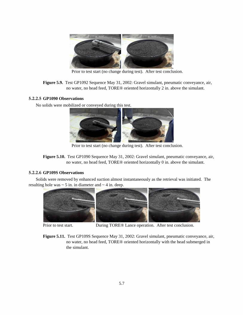
5.7
Prior to test start (no change during test). After test conclusion.
Figure 5.9. Test GP1092 Sequence May 31, 2002: Gravel simulant, pneumatic conveyance, air,
no water, no head feed, TORE® oriented horizontally 2 in. above the simulant.
5.2.2.5 GP1090 Observations
No solids were mobilized or conveyed during this test.
Prior to test start (no change during test). After test conclusion.
Figure 5.10. Test GP1090 Sequence May 31, 2002: Gravel simulant, pneumatic conveyance, air,
no water, no head feed, TORE® oriented horizontally 0 in. above the simulant.
5.2.2.6 GP109S Observations
Solids were removed by enhanced suction almost instantaneously as the retrieval was initiated. The
resulting hole was ~ 5 in. in diameter and ~ 4 in. deep.
Prior to test start. During TORE® Lance operation. After test conclusion.
Figure 5.11. Test GP109S Sequence May 31, 2002: Gravel simulant, pneumatic conveyance, air,
no water, no head feed, TORE® oriented horizontally with the head submerged in
the simulant.
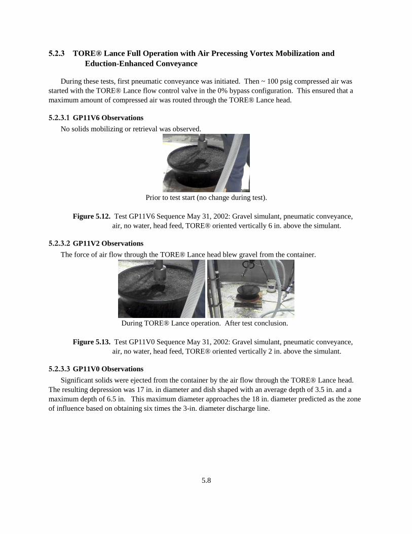
5.8
5.2.3 TORE® Lance Full Operation with Air Precessing Vortex Mobilization and
Eduction-Enhanced Conveyance
During these tests, first pneumatic conveyance was initiated. Then ~ 100 psig compressed air was
started with the TORE® Lance flow control valve in the 0% bypass configuration. This ensured that a
maximum amount of compressed air was routed through the TORE® Lance head.
5.2.3.1 GP11V6 Observations
No solids mobilizing or retrieval was observed.
Prior to test start (no change during test).
Figure 5.12. Test GP11V6 Sequence May 31, 2002: Gravel simulant, pneumatic conveyance,
air, no water, head feed, TORE® oriented vertically 6 in. above the simulant.
5.2.3.2 GP11V2 Observations
The force of air flow through the TORE® Lance head blew gravel from the container.
During TORE® Lance operation. After test conclusion.
Figure 5.13. Test GP11V0 Sequence May 31, 2002: Gravel simulant, pneumatic conveyance,
air, no water, head feed, TORE® oriented vertically 2 in. above the simulant.
5.2.3.3 GP11V0 Observations
Significant solids were ejected from the container by the air flow through the TORE® Lance head.
The resulting depression was 17 in. in diameter and dish shaped with an average depth of 3.5 in. and a
maximum depth of 6.5 in. This maximum diameter approaches the 18 in. diameter predicted as the zone
of influence based on obtaining six times the 3-in. diameter discharge line.
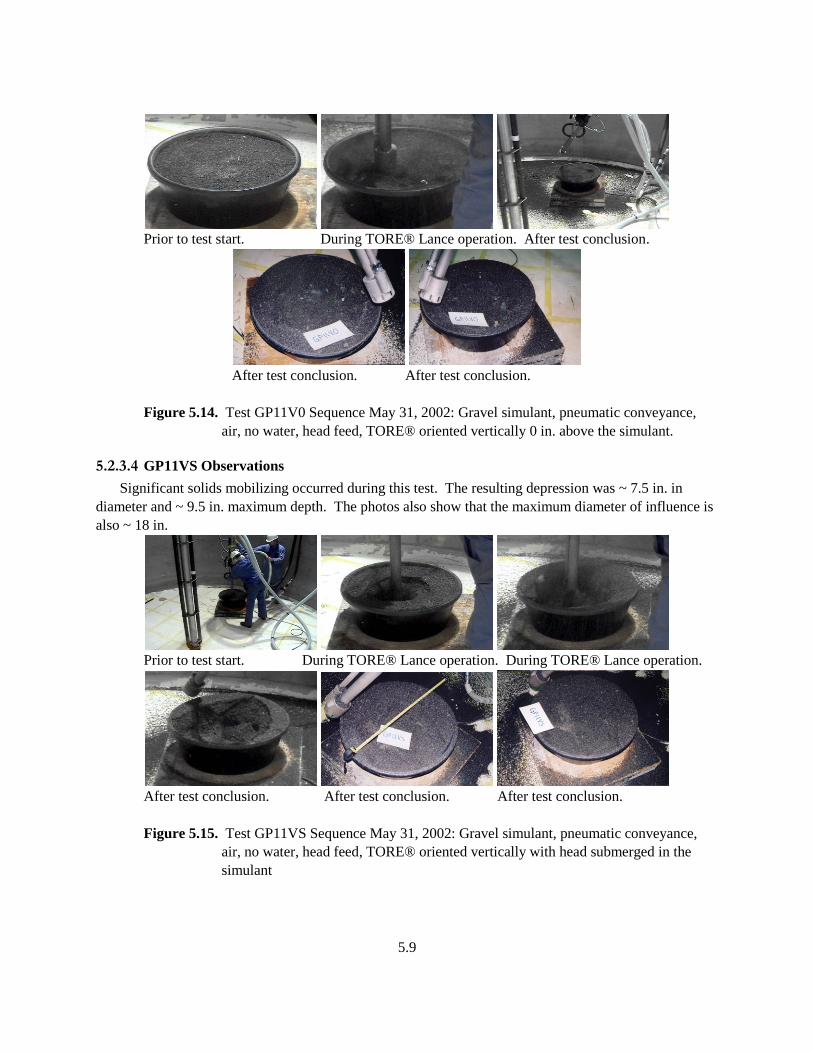
5.9
Prior to test start. During TORE® Lance operation. After test conclusion.
After test conclusion. After test conclusion.
Figure 5.14. Test GP11V0 Sequence May 31, 2002: Gravel simulant, pneumatic conveyance,
air, no water, head feed, TORE® oriented vertically 0 in. above the simulant.
5.2.3.4 GP11VS Observations
Significant solids mobilizing occurred during this test. The resulting depression was ~ 7.5 in. in
diameter and ~ 9.5 in. maximum depth. The photos also show that the maximum diameter of influence is
also ~ 18 in.
Prior to test start. During TORE® Lance operation. During TORE® Lance operation.
After test conclusion. After test conclusion. After test conclusion.
Figure 5.15. Test GP11VS Sequence May 31, 2002: Gravel simulant, pneumatic conveyance,
air, no water, head feed, TORE® oriented vertically with head submerged in the
simulant

5.10
5.2.3.5 GV11VSS Observations
At the start of this test the TORE® Lance head was very close to the bottom of the container. The
suction caused the container bottom to deform and restrict flow to the TORE® Lance retrieval line. The
head was raised slightly and significant mobilizing and retrieval occurred.
Prior to test start. During TORE® Lance operation. During TORE® Lance operation.
After test conclusion. After test conclusion. After test conclusion.
Figure 5.16. Test GP11VSS Sequence May 31, 2002: Gravel simulant, pneumatic conveyance,
air, no water, head feed, TORE® oriented vertically with head submerged deeper
into the simulant.
5.2.3.6 GP119S Observations
With the TORE® Lance head at ~ 90 degrees to the gravel a slit-shaped hole resulted immediately
after start of operation.
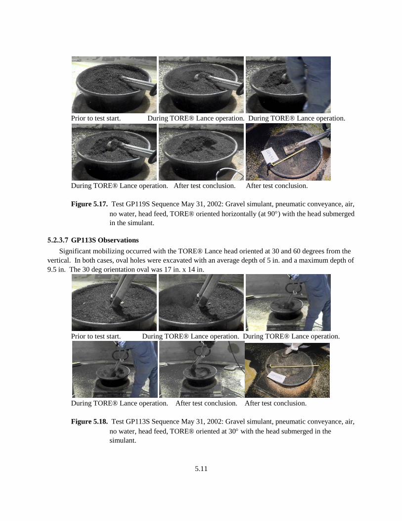
5.11
Prior to test start. During TORE® Lance operation. During TORE® Lance operation.
During TORE® Lance operation. After test conclusion. After test conclusion.
Figure 5.17. Test GP119S Sequence May 31, 2002: Gravel simulant, pneumatic conveyance, air,
no water, head feed, TORE® oriented horizontally (at 90) with the head submerged
in the simulant.
5.2.3.7 GP113S Observations
Significant mobilizing occurred with the TORE® Lance head oriented at 30 and 60 degrees from the
vertical. In both cases, oval holes were excavated with an average depth of 5 in. and a maximum depth of
9.5 in. The 30 deg orientation oval was 17 in. x 14 in.
Prior to test start. During TORE® Lance operation. During TORE® Lance operation.
During TORE® Lance operation. After test conclusion. After test conclusion.
Figure 5.18. Test GP113S Sequence May 31, 2002: Gravel simulant, pneumatic conveyance, air,
no water, head feed, TORE® oriented at 30 with the head submerged in the
simulant.
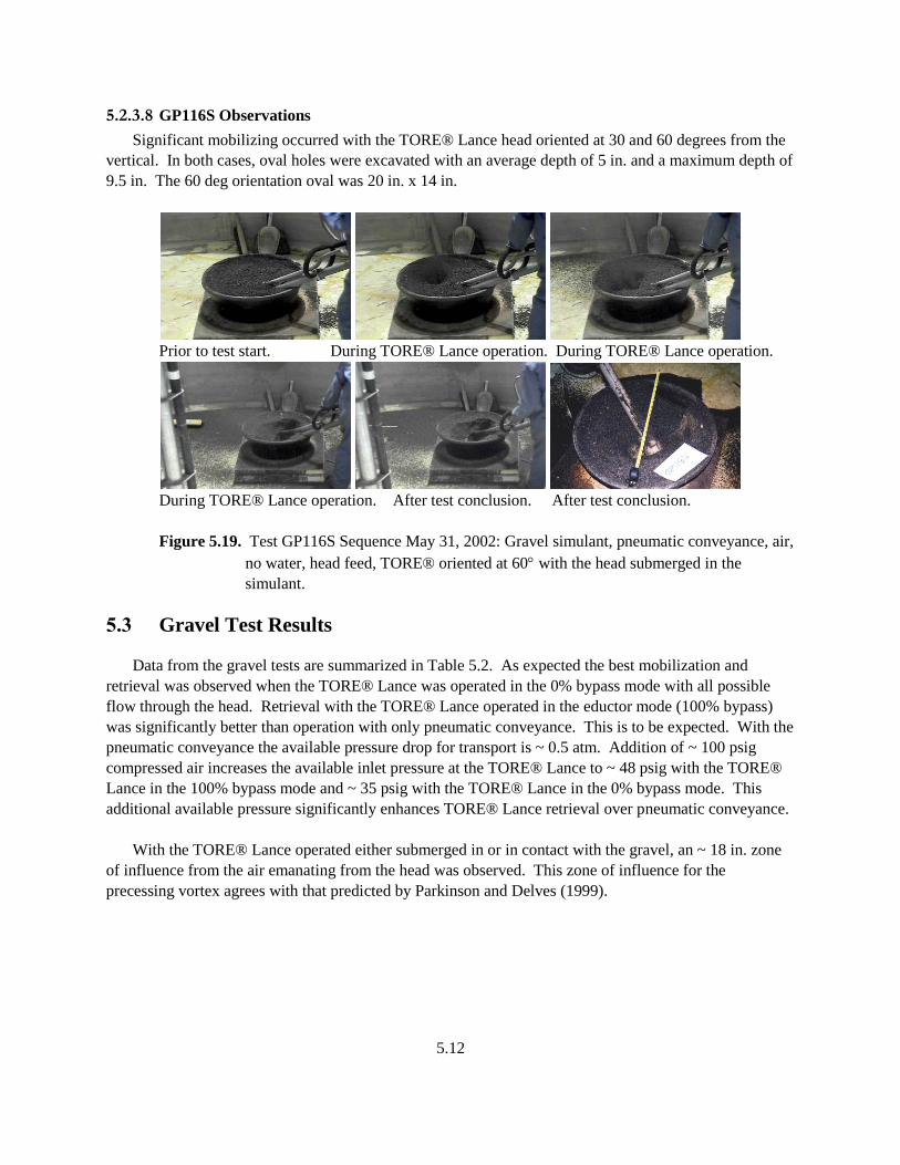
5.12
5.2.3.8 GP116S Observations
Significant mobilizing occurred with the TORE® Lance head oriented at 30 and 60 degrees from the
vertical. In both cases, oval holes were excavated with an average depth of 5 in. and a maximum depth of
9.5 in. The 60 deg orientation oval was 20 in. x 14 in.
Prior to test start. During TORE® Lance operation. During TORE® Lance operation.
During TORE® Lance operation. After test conclusion. After test conclusion.
Figure 5.19. Test GP116S Sequence May 31, 2002: Gravel simulant, pneumatic conveyance, air,
no water, head feed, TORE® oriented at 60 with the head submerged in the
simulant.
5.3 Gravel Test Results
Data from the gravel tests are summarized in Table 5.2. As expected the best mobilization and
retrieval was observed when the TORE® Lance was operated in the 0% bypass mode with all possible
flow through the head. Retrieval with the TORE® Lance operated in the eductor mode (100% bypass)
was significantly better than operation with only pneumatic conveyance. This is to be expected. With the
pneumatic conveyance the available pressure drop for transport is ~ 0.5 atm. Addition of ~ 100 psig
compressed air increases the available inlet pressure at the TORE® Lance to ~ 48 psig with the TORE®
Lance in the 100% bypass mode and ~ 35 psig with the TORE® Lance in the 0% bypass mode. This
additional available pressure significantly enhances TORE® Lance retrieval over pneumatic conveyance.
With the TORE® Lance operated either submerged in or in contact with the gravel, an ~ 18 in. zone
of influence from the air emanating from the head was observed. This zone of influence for the
precessing vortex agrees with that predicted by Parkinson and Delves (1999).
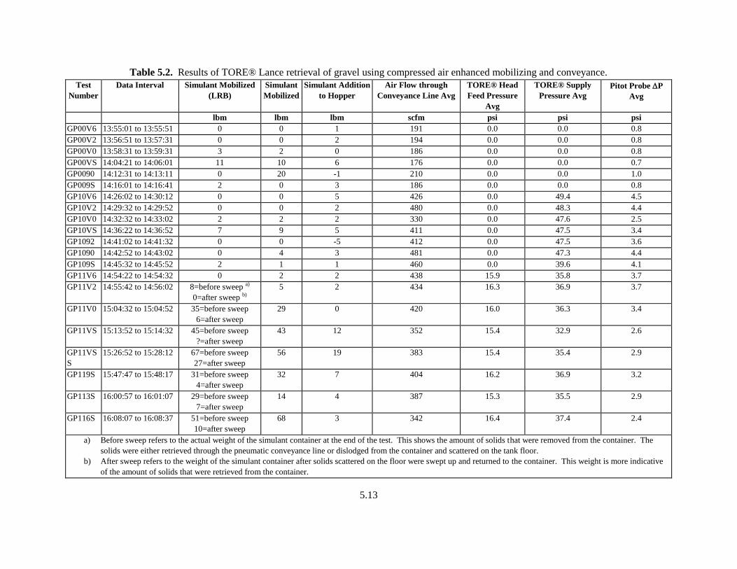
5.13
Table 5.2. Results of TORE® Lance retrieval of gravel using compressed air enhanced mobilizing and conveyance.
Test
Number
Data Interval Simulant Mobilized
(LRB)
Simulant
Mobilized
Simulant Addition
to Hopper
Air Flow through
Conveyance Line Avg
TORE® Head
Feed Pressure
Avg
TORE® Supply
Pressure Avg
Pitot Probe P
Avg
lbm lbm lbm scfm psi psi psi
GP00V6 13:55:01 to 13:55:51 0 0 1 191 0.0 0.0 0.8
GP00V2 13:56:51 to 13:57:31 0 0 2 194 0.0 0.0 0.8
GP00V0 13:58:31 to 13:59:31 3 2 0 186 0.0 0.0 0.8
GP00VS 14:04:21 to 14:06:01 11 10 6 176 0.0 0.0 0.7
GP0090 14:12:31 to 14:13:11 0 20 -1 210 0.0 0.0 1.0
GP009S 14:16:01 to 14:16:41 2 0 3 186 0.0 0.0 0.8
GP10V6 14:26:02 to 14:30:12 0 0 5 426 0.0 49.4 4.5
GP10V2 14:29:32 to 14:29:52 0 0 2 480 0.0 48.3 4.4
GP10V0 14:32:32 to 14:33:02 2 2 2 330 0.0 47.6 2.5
GP10VS 14:36:22 to 14:36:52 7 9 5 411 0.0 47.5 3.4
GP1092 14:41:02 to 14:41:32 0 0 -5 412 0.0 47.5 3.6
GP1090 14:42:52 to 14:43:02 0 4 3 481 0.0 47.3 4.4
GP109S 14:45:32 to 14:45:52 2 1 1 460 0.0 39.6 4.1
GP11V6 14:54:22 to 14:54:32 0 2 2 438 15.9 35.8 3.7
GP11V2 14:55:42 to 14:56:02 8=before sweep a)
0=after sweep b)
5 2 434 16.3 36.9 3.7
GP11V0 15:04:32 to 15:04:52 35=before sweep
6=after sweep
29 0 420 16.0 36.3 3.4
GP11VS 15:13:52 to 15:14:32 45=before sweep
?=after sweep
43 12 352 15.4 32.9 2.6
GP11VS
S
15:26:52 to 15:28:12 67=before sweep
27=after sweep
56 19 383 15.4 35.4 2.9
GP119S 15:47:47 to 15:48:17 31=before sweep
4=after sweep
32 7 404 16.2 36.9 3.2
GP113S 16:00:57 to 16:01:07 29=before sweep
7=after sweep
14 4 387 15.3 35.5 2.9
GP116S 16:08:07 to 16:08:37 51=before sweep
10=after sweep
68 3 342 16.4 37.4 2.4
a) Before sweep refers to the actual weight of the simulant container at the end of the test. This shows the amount of solids that were removed from the container. The
solids were either retrieved through the pneumatic conveyance line or dislodged from the container and scattered on the tank floor.
b) After sweep refers to the weight of the simulant container after solids scattered on the floor were swept up and returned to the container. This weight is more indicative
of the amount of solids that were retrieved from the container.

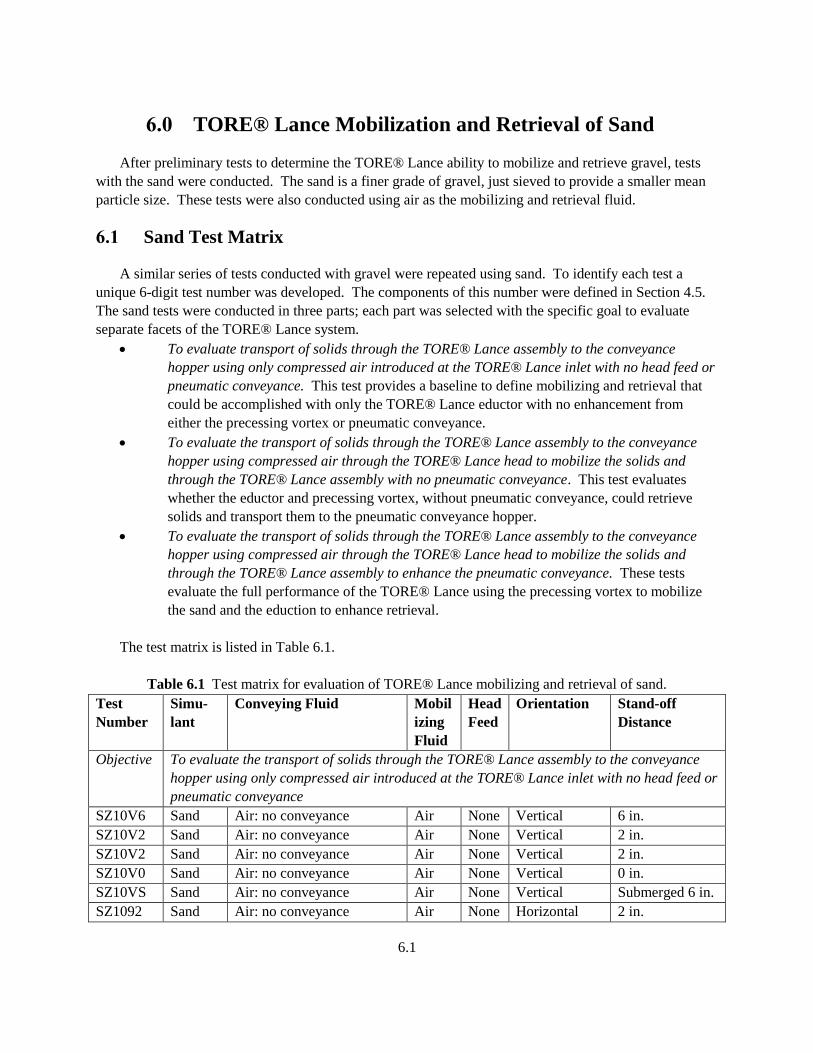
6.1
6.0 TORE® Lance Mobilization and Retrieval of Sand
After preliminary tests to determine the TORE® Lance ability to mobilize and retrieve gravel, tests
with the sand were conducted. The sand is a finer grade of gravel, just sieved to provide a smaller mean
particle size. These tests were also conducted using air as the mobilizing and retrieval fluid.
6.1 Sand Test Matrix
A similar series of tests conducted with gravel were repeated using sand. To identify each test a
unique 6-digit test number was developed. The components of this number were defined in Section 4.5.
The sand tests were conducted in three parts; each part was selected with the specific goal to evaluate
separate facets of the TORE® Lance system.
To evaluate transport of solids through the TORE® Lance assembly to the conveyance
hopper using only compressed air introduced at the TORE® Lance inlet with no head feed or
pneumatic conveyance. This test provides a baseline to define mobilizing and retrieval that
could be accomplished with only the TORE® Lance eductor with no enhancement from
either the precessing vortex or pneumatic conveyance.
To evaluate the transport of solids through the TORE® Lance assembly to the conveyance
hopper using compressed air through the TORE® Lance head to mobilize the solids and
through the TORE® Lance assembly with no pneumatic conveyance. This test evaluates
whether the eductor and precessing vortex, without pneumatic conveyance, could retrieve
solids and transport them to the pneumatic conveyance hopper.
To evaluate the transport of solids through the TORE® Lance assembly to the conveyance
hopper using compressed air through the TORE® Lance head to mobilize the solids and
through the TORE® Lance assembly to enhance the pneumatic conveyance. These tests
evaluate the full performance of the TORE® Lance using the precessing vortex to mobilize
the sand and the eduction to enhance retrieval.
The test matrix is listed in Table 6.1.
Table 6.1 Test matrix for evaluation of TORE® Lance mobilizing and retrieval of sand.
Test
Number
Simu-
lant
Conveying Fluid Mobil
izing
Fluid
Head
Feed
Orientation Stand-off
Distance
Objective To evaluate the transport of solids through the TORE® Lance assembly to the conveyance
hopper using only compressed air introduced at the TORE® Lance inlet with no head feed or
pneumatic conveyance
SZ10V6 Sand Air: no conveyance Air None Vertical 6 in.
SZ10V2 Sand Air: no conveyance Air None Vertical 2 in.
SZ10V2 Sand Air: no conveyance Air None Vertical 2 in.
SZ10V0 Sand Air: no conveyance Air None Vertical 0 in.
SZ10VS Sand Air: no conveyance Air None Vertical Submerged 6 in.
SZ1092 Sand Air: no conveyance Air None Horizontal 2 in.
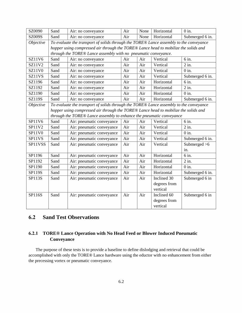
6.2
SZ0090 Sand Air: no conveyance Air None Horizontal 0 in.
SZ009S Sand Air: no conveyance Air None Horizontal Submerged 6 in.
Objective To evaluate the transport of solids through the TORE® Lance assembly to the conveyance
hopper using compressed air through the TORE® Lance head to mobilize the solids and
through the TORE® Lance assembly with no pneumatic conveyance.
SZ11V6 Sand Air: no conveyance Air Air Vertical 6 in.
SZ11V2 Sand Air: no conveyance Air Air Vertical 2 in.
SZ11V0 Sand Air: no conveyance Air Air Vertical 0 in.
SZ11VS Sand Air: no conveyance Air Air Vertical Submerged 6 in.
SZ1196 Sand Air: no conveyance Air Air Horizontal 6 in.
SZ1192 Sand Air: no conveyance Air Air Horizontal 2 in.
SZ1190 Sand Air: no conveyance Air Air Horizontal 0 in.
SZ119S Sand Air: no conveyance Air Air Horizontal Submerged 6 in.
Objective To evaluate the transport of solids through the TORE® Lance assembly to the conveyance
hopper using compressed air through the TORE® Lance head to mobilize the solids and
through the TORE® Lance assembly to enhance the pneumatic conveyance
SP11V6 Sand Air: pneumatic conveyance Air Air Vertical 6 in.
SP11V2 Sand Air: pneumatic conveyance Air Air Vertical 2 in.
SP11V0 Sand Air: pneumatic conveyance Air Air Vertical 0 in.
SP11VS Sand Air: pneumatic conveyance Air Air Vertical Submerged 6 in.
SP11VSS Sand Air: pneumatic conveyance Air Air Vertical Submerged >6
in.
SP1196 Sand Air: pneumatic conveyance Air Air Horizontal 6 in.
SP1192 Sand Air: pneumatic conveyance Air Air Horizontal 2 in.
SP1190 Sand Air: pneumatic conveyance Air Air Horizontal 0 in.
SP119S Sand Air: pneumatic conveyance Air Air Horizontal Submerged 6 in.
SP113S Sand Air: pneumatic conveyance Air Air Inclined 30
degrees from
vertical
Submerged 6 in
SP116S Sand Air: pneumatic conveyance Air Air Inclined 60
degrees from
vertical
Submerged 6 in
6.2 Sand Test Observations
6.2.1 TORE® Lance Operation with No Head Feed or Blower Induced Pneumatic
Conveyance
The purpose of these tests is to provide a baseline to define dislodging and retrieval that could be
accomplished with only the TORE® Lance hardware using the eductor with no enhancement from either
the precessing vortex or pneumatic conveyance.
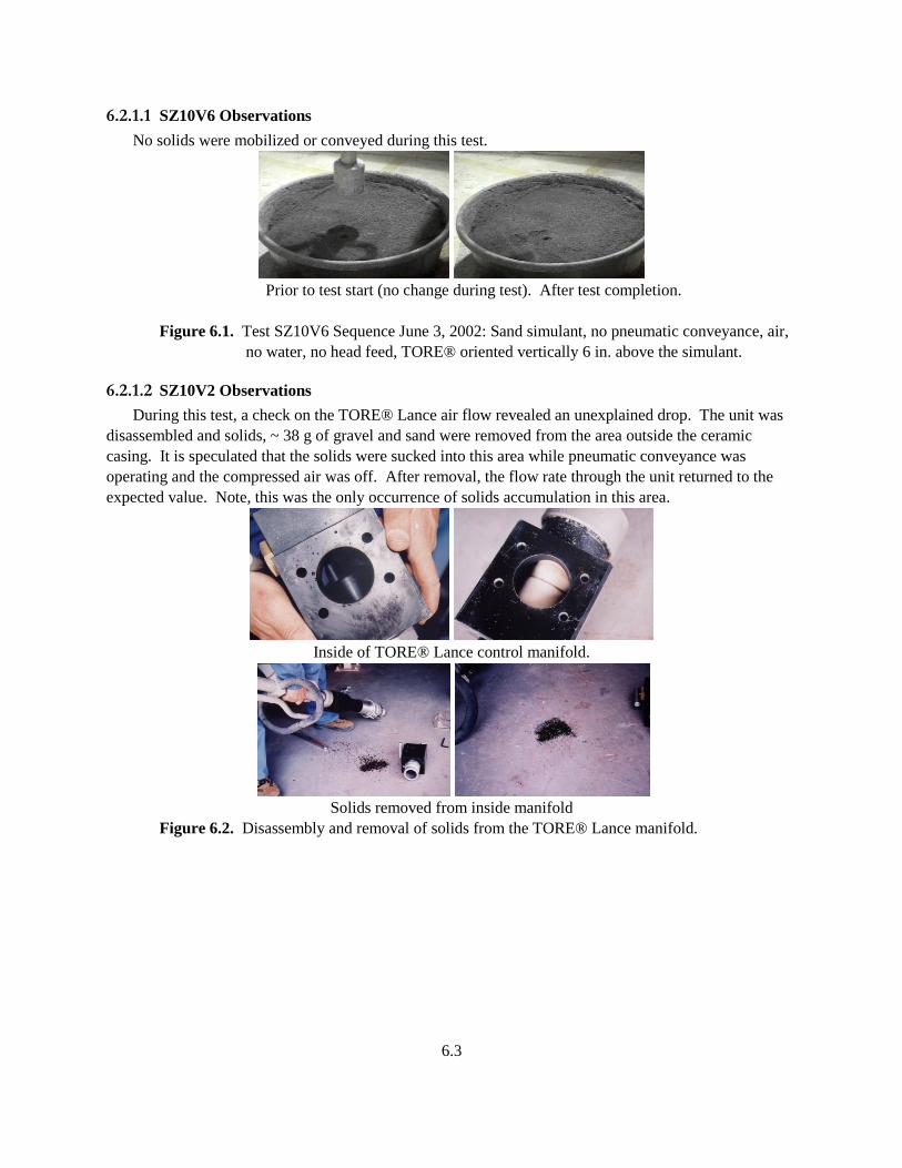
6.3
6.2.1.1 SZ10V6 Observations
No solids were mobilized or conveyed during this test.
Prior to test start (no change during test). After test completion.
Figure 6.1. Test SZ10V6 Sequence June 3, 2002: Sand simulant, no pneumatic conveyance, air,
no water, no head feed, TORE® oriented vertically 6 in. above the simulant.
6.2.1.2 SZ10V2 Observations
During this test, a check on the TORE® Lance air flow revealed an unexplained drop. The unit was
disassembled and solids, ~ 38 g of gravel and sand were removed from the area outside the ceramic
casing. It is speculated that the solids were sucked into this area while pneumatic conveyance was
operating and the compressed air was off. After removal, the flow rate through the unit returned to the
expected value. Note, this was the only occurrence of solids accumulation in this area.
Inside of TORE® Lance control manifold.
Solids removed from inside manifold
Figure 6.2. Disassembly and removal of solids from the TORE® Lance manifold.
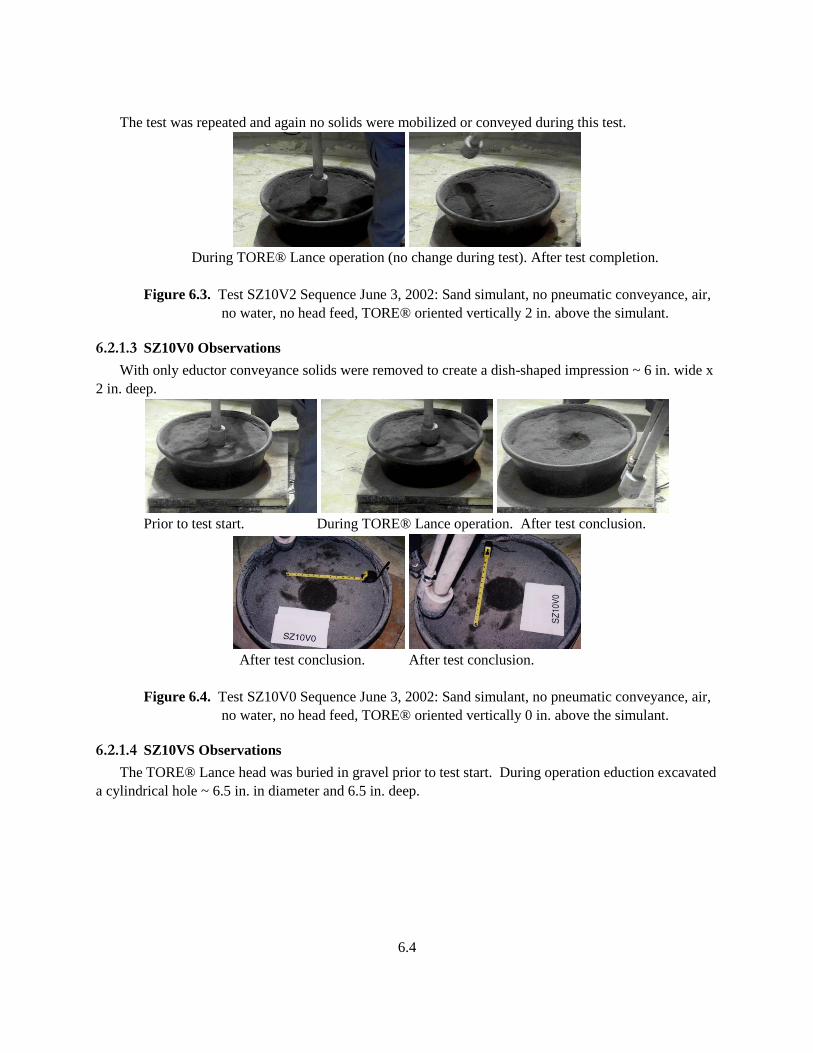
6.4
The test was repeated and again no solids were mobilized or conveyed during this test.
During TORE® Lance operation (no change during test). After test completion.
Figure 6.3. Test SZ10V2 Sequence June 3, 2002: Sand simulant, no pneumatic conveyance, air,
no water, no head feed, TORE® oriented vertically 2 in. above the simulant.
6.2.1.3 SZ10V0 Observations
With only eductor conveyance solids were removed to create a dish-shaped impression ~ 6 in. wide x
2 in. deep.
Prior to test start. During TORE® Lance operation. After test conclusion.
After test conclusion. After test conclusion.
Figure 6.4. Test SZ10V0 Sequence June 3, 2002: Sand simulant, no pneumatic conveyance, air,
no water, no head feed, TORE® oriented vertically 0 in. above the simulant.
6.2.1.4 SZ10VS Observations
The TORE® Lance head was buried in gravel prior to test start. During operation eduction excavated
a cylindrical hole ~ 6.5 in. in diameter and 6.5 in. deep.

6.5
Prior to test start. During TORE® Lance operation. After test completion.
After test completion. After test completion.
Figure 6.5. Test SZ10VS Sequence June 3, 2002: Sand simulant, no pneumatic conveyance, air,
no water, no head feed, TORE® oriented vertically with head submerged in the
simulant.
6.2.1.5 SZ1092 Observations
No solids were mobilized or conveyed during this test.
Prior to test start (no change during test). After test conclusion.
Figure 6.6. Test SZ1092 Sequence June 3, 2002: Sand simulant, no pneumatic conveyance, air,
no water, no head feed, TORE® oriented horizontally (at 90) 2 in. above the
simulant.
6.2.1.6 SZ1090 Observations
No solids were mobilized or conveyed during this test.
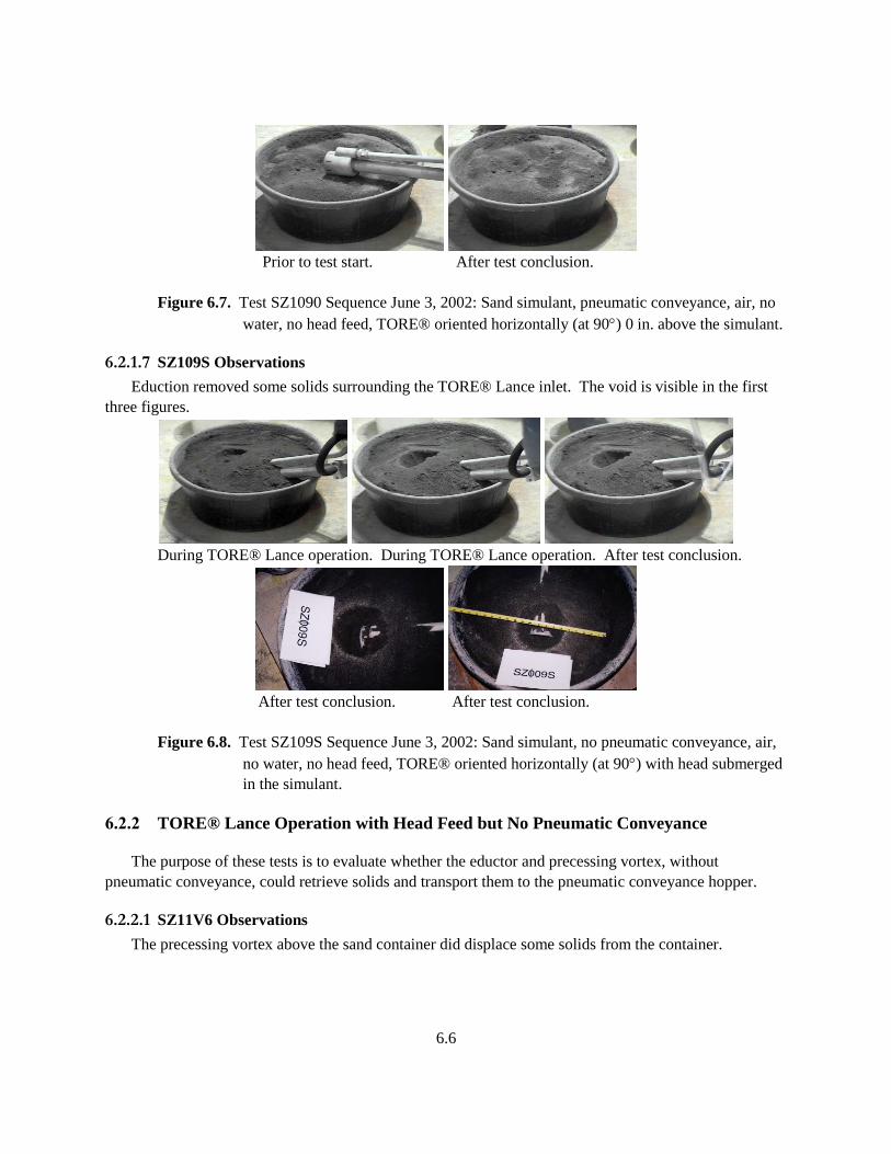
6.6
Prior to test start. After test conclusion.
Figure 6.7. Test SZ1090 Sequence June 3, 2002: Sand simulant, pneumatic conveyance, air, no
water, no head feed, TORE® oriented horizontally (at 90) 0 in. above the simulant.
6.2.1.7 SZ109S Observations
Eduction removed some solids surrounding the TORE® Lance inlet. The void is visible in the first
three figures.
During TORE® Lance operation. During TORE® Lance operation. After test conclusion.
After test conclusion. After test conclusion.
Figure 6.8. Test SZ109S Sequence June 3, 2002: Sand simulant, no pneumatic conveyance, air,
no water, no head feed, TORE® oriented horizontally (at 90) with head submerged
in the simulant.
6.2.2 TORE® Lance Operation with Head Feed but No Pneumatic Conveyance
The purpose of these tests is to evaluate whether the eductor and precessing vortex, without
pneumatic conveyance, could retrieve solids and transport them to the pneumatic conveyance hopper.
6.2.2.1 SZ11V6 Observations
The precessing vortex above the sand container did displace some solids from the container.
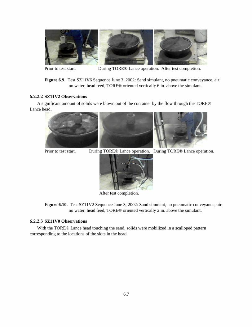
6.7
Prior to test start. During TORE® Lance operation. After test completion.
Figure 6.9. Test SZ11V6 Sequence June 3, 2002: Sand simulant, no pneumatic conveyance, air,
no water, head feed, TORE® oriented vertically 6 in. above the simulant.
6.2.2.2 SZ11V2 Observations
A significant amount of solids were blown out of the container by the flow through the TORE®
Lance head.
Prior to test start. During TORE® Lance operation. During TORE® Lance operation.
After test completion.
Figure 6.10. Test SZ11V2 Sequence June 3, 2002: Sand simulant, no pneumatic conveyance, air,
no water, head feed, TORE® oriented vertically 2 in. above the simulant.
6.2.2.3 SZ11V0 Observations
With the TORE® Lance head touching the sand, solids were mobilized in a scalloped pattern
corresponding to the locations of the slots in the head.
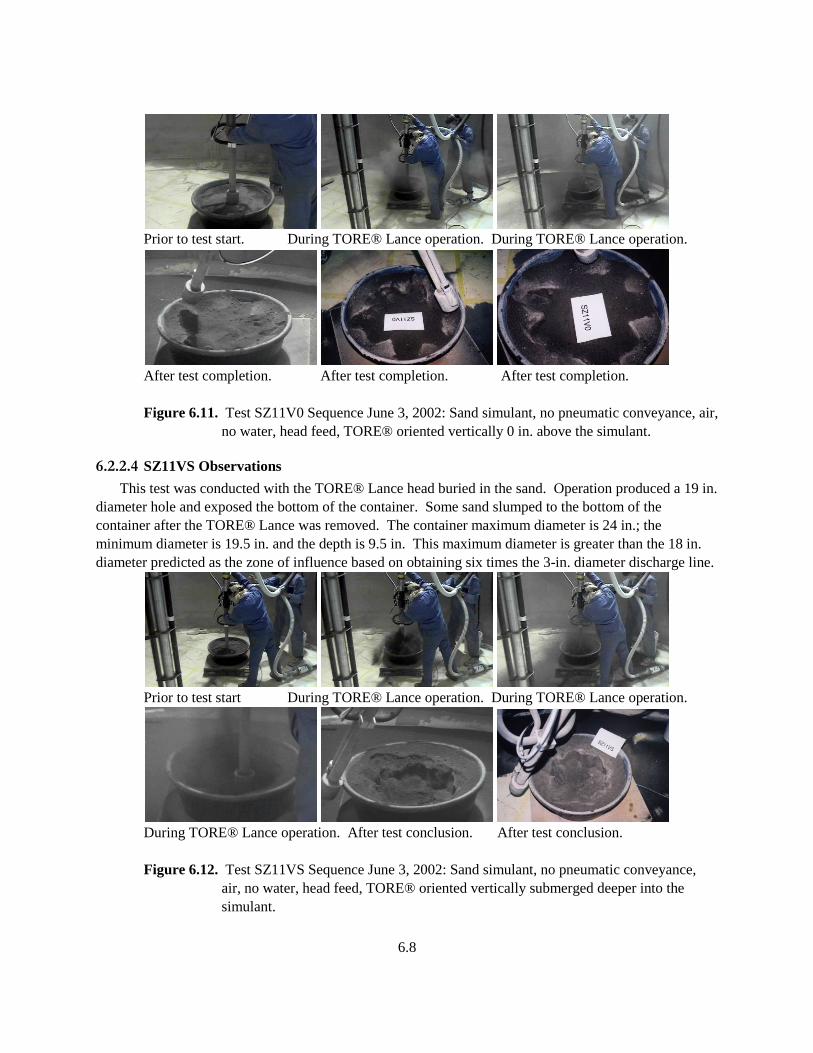
6.8
Prior to test start. During TORE® Lance operation. During TORE® Lance operation.
After test completion. After test completion. After test completion.
Figure 6.11. Test SZ11V0 Sequence June 3, 2002: Sand simulant, no pneumatic conveyance, air,
no water, head feed, TORE® oriented vertically 0 in. above the simulant.
6.2.2.4 SZ11VS Observations
This test was conducted with the TORE® Lance head buried in the sand. Operation produced a 19 in.
diameter hole and exposed the bottom of the container. Some sand slumped to the bottom of the
container after the TORE® Lance was removed. The container maximum diameter is 24 in.; the
minimum diameter is 19.5 in. and the depth is 9.5 in. This maximum diameter is greater than the 18 in.
diameter predicted as the zone of influence based on obtaining six times the 3-in. diameter discharge line.
Prior to test start During TORE® Lance operation. During TORE® Lance operation.
During TORE® Lance operation. After test conclusion. After test conclusion.
Figure 6.12. Test SZ11VS Sequence June 3, 2002: Sand simulant, no pneumatic conveyance,
air, no water, head feed, TORE® oriented vertically submerged deeper into the
simulant.

6.9
6.2.2.5 SZ1196 Observations
During this test with the TORE® Lance oriented horizontally at ~ 6 in. above the sand, significant
solids were displaced by the air flow through the head.
Prior to test start. During TORE® Lance operation. During TORE® Lance operation
. After test completion.
Figure 6.13. Test SZ1196 Sequence June 3, 2002: Sand simulant, no pneumatic conveyance, air,
no water, head feed, TORE® oriented horizontally (at 90) with head 6 in. above the
simulant.
6.2.2.6 SZ1192 Observations
With the TORE® Lance head 2 in. above the simulant, the jets from slots projecting toward the solids
excavated large holes in the path of the air flow and excavated one side of the container.
During TORE® Lance operation. During TORE® Lance operation. During TORE® Lance operation
After test completion. After test completion. After test completion.
Figure 6.14. Test SZ1192 Sequence June 3, 2002: Sand simulant, no pneumatic conveyance, air,
no water, head feed, TORE® oriented horizontally (at 90) with head 2 in. above the
simulant.
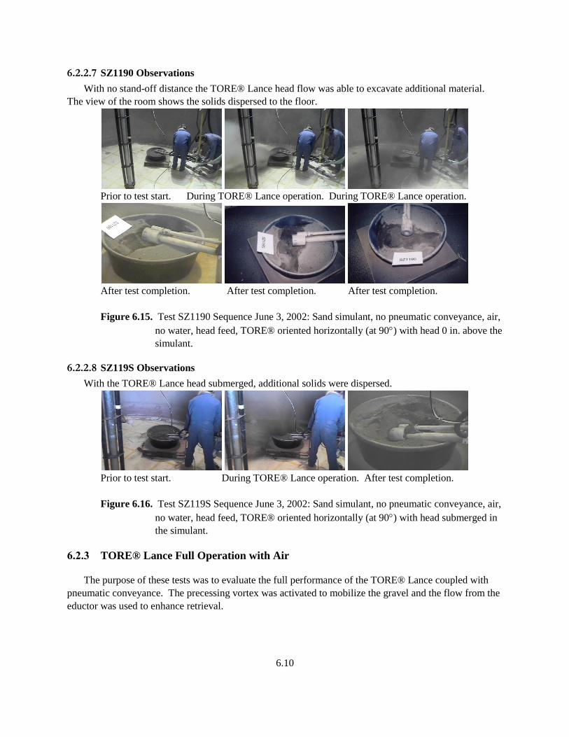
6.10
6.2.2.7 SZ1190 Observations
With no stand-off distance the TORE® Lance head flow was able to excavate additional material.
The view of the room shows the solids dispersed to the floor.
Prior to test start. During TORE® Lance operation. During TORE® Lance operation.
After test completion. After test completion. After test completion.
Figure 6.15. Test SZ1190 Sequence June 3, 2002: Sand simulant, no pneumatic conveyance, air,
no water, head feed, TORE® oriented horizontally (at 90) with head 0 in. above the
simulant.
6.2.2.8 SZ119S Observations
With the TORE® Lance head submerged, additional solids were dispersed.
Prior to test start. During TORE® Lance operation. After test completion.
Figure 6.16. Test SZ119S Sequence June 3, 2002: Sand simulant, no pneumatic conveyance, air,
no water, head feed, TORE® oriented horizontally (at 90) with head submerged in
the simulant.
6.2.3 TORE® Lance Full Operation with Air
The purpose of these tests was to evaluate the full performance of the TORE® Lance coupled with
pneumatic conveyance. The precessing vortex was activated to mobilize the gravel and the flow from the
eductor was used to enhance retrieval.
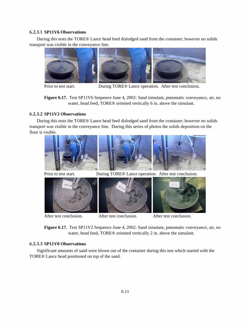
6.11
6.2.3.1 SP11V6 Observations
During this tests the TORE® Lance head feed dislodged sand from the container; however no solids
transport was visible in the conveyance line.
Prior to test start. During TORE® Lance operation. After test conclusion.
Figure 6.17. Test SP11V6 Sequence June 4, 2002: Sand simulant, pneumatic conveyance, air, no
water, head feed, TORE® oriented vertically 6 in. above the simulant.
6.2.3.2 SP11V2 Observations
During this tests the TORE® Lance head feed dislodged sand from the container; however no solids
transport was visible in the conveyance line. During this series of photos the solids deposition on the
floor is visible.
Prior to test start. During TORE® Lance operation. After test conclusion.
After test conclusion. After test conclusion. After test conclusion.
Figure 6.17. Test SP11V2 Sequence June 4, 2002: Sand simulant, pneumatic conveyance, air, no
water, head feed, TORE® oriented vertically 2 in. above the simulant.
6.2.3.3 SP11V0 Observations
Significant amounts of sand were blown out of the container during this test which started with the
TORE® Lance head positioned on top of the sand.
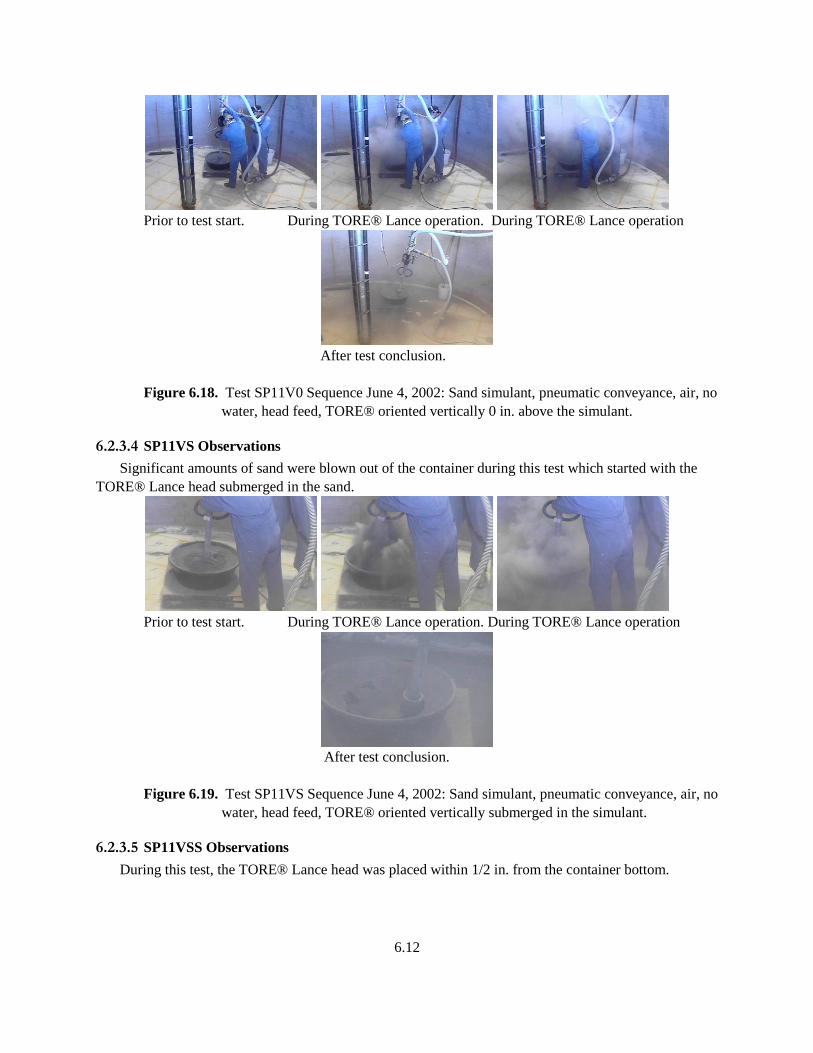
6.12
Prior to test start. During TORE® Lance operation. During TORE® Lance operation
After test conclusion.
Figure 6.18. Test SP11V0 Sequence June 4, 2002: Sand simulant, pneumatic conveyance, air, no
water, head feed, TORE® oriented vertically 0 in. above the simulant.
6.2.3.4 SP11VS Observations
Significant amounts of sand were blown out of the container during this test which started with the
TORE® Lance head submerged in the sand.
Prior to test start. During TORE® Lance operation. During TORE® Lance operation
After test conclusion.
Figure 6.19. Test SP11VS Sequence June 4, 2002: Sand simulant, pneumatic conveyance, air, no
water, head feed, TORE® oriented vertically submerged in the simulant.
6.2.3.5 SP11VSS Observations
During this test, the TORE® Lance head was placed within 1/2 in. from the container bottom.
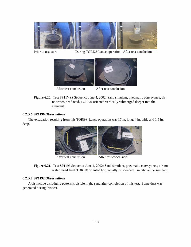
6.13
Prior to test start. During TORE® Lance operation. After test conclusion
After test conclusion After test conclusion
Figure 6.20. Test SP11VSS Sequence June 4, 2002: Sand simulant, pneumatic conveyance, air,
no water, head feed, TORE® oriented vertically submerged deeper into the
simulant.
6.2.3.6 SP1196 Observations
The excavation resulting from this TORE® Lance operation was 17 in. long, 4 in. wide and 1.5 in.
deep.
After test conclusion After test conclusion
Figure 6.21. Test SP1196 Sequence June 4, 2002: Sand simulant, pneumatic conveyance, air, no
water, head feed, TORE® oriented horizontally, suspended 6 in. above the simulant.
6.2.3.7 SP1192 Observations
A distinctive dislodging pattern is visible in the sand after completion of this test. Some dust was
generated during this test.
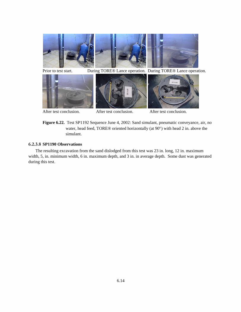
6.14
Prior to test start. During TORE® Lance operation. During TORE® Lance operation.
After test conclusion. After test conclusion. After test conclusion.
Figure 6.22. Test SP1192 Sequence June 4, 2002: Sand simulant, pneumatic conveyance, air, no
water, head feed, TORE® oriented horizontally (at 90) with head 2 in. above the
simulant.
6.2.3.8 SP1190 Observations
The resulting excavation from the sand dislodged from this test was 23 in. long, 12 in. maximum
width, 5, in. minimum width, 6 in. maximum depth, and 3 in. in average depth. Some dust was generated
during this test.
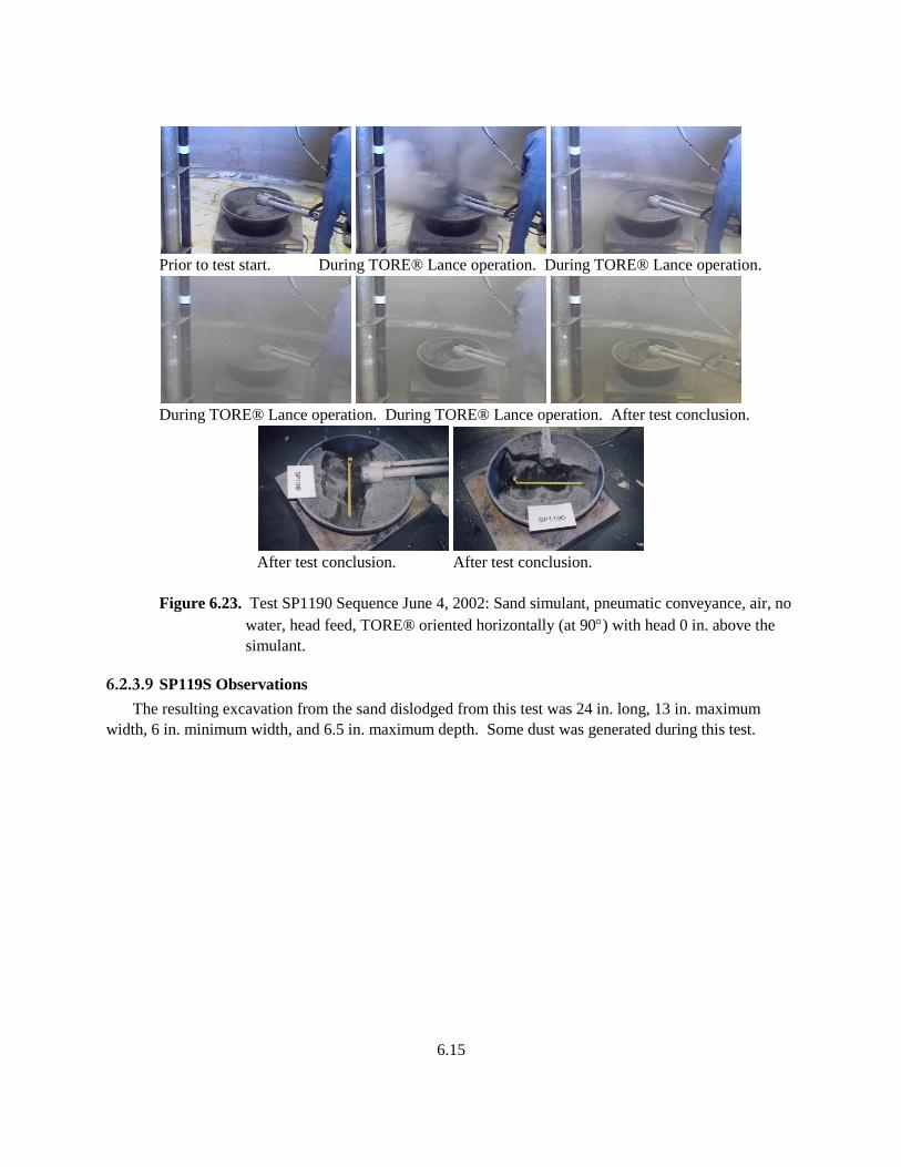
6.15
Prior to test start. During TORE® Lance operation. During TORE® Lance operation.
During TORE® Lance operation. During TORE® Lance operation. After test conclusion.
After test conclusion. After test conclusion.
Figure 6.23. Test SP1190 Sequence June 4, 2002: Sand simulant, pneumatic conveyance, air, no
water, head feed, TORE® oriented horizontally (at 90) with head 0 in. above the
simulant.
6.2.3.9 SP119S Observations
The resulting excavation from the sand dislodged from this test was 24 in. long, 13 in. maximum
width, 6 in. minimum width, and 6.5 in. maximum depth. Some dust was generated during this test.
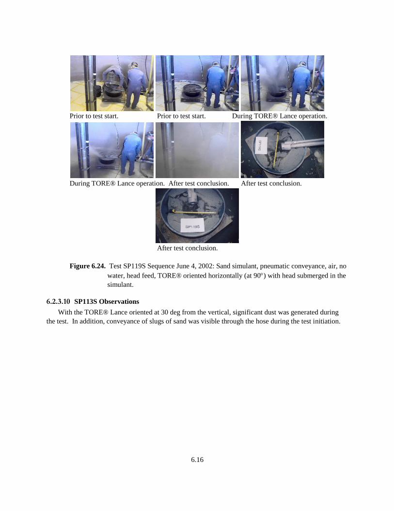
6.16
Prior to test start. Prior to test start. During TORE® Lance operation.
During TORE® Lance operation. After test conclusion. After test conclusion.
After test conclusion.
Figure 6.24. Test SP119S Sequence June 4, 2002: Sand simulant, pneumatic conveyance, air, no
water, head feed, TORE® oriented horizontally (at 90) with head submerged in the
simulant.
6.2.3.10 SP113S Observations
With the TORE® Lance oriented at 30 deg from the vertical, significant dust was generated during
the test. In addition, conveyance of slugs of sand was visible through the hose during the test initiation.
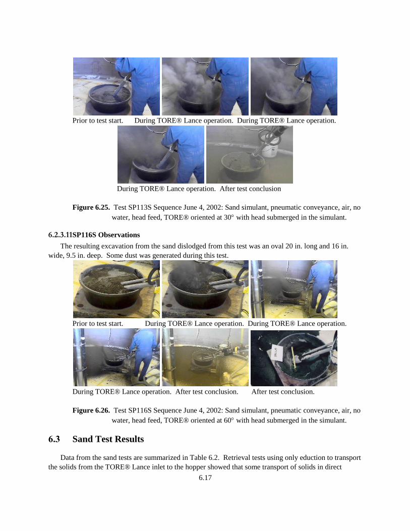
6.17
Prior to test start. During TORE® Lance operation. During TORE® Lance operation.
During TORE® Lance operation. After test conclusion
Figure 6.25. Test SP113S Sequence June 4, 2002: Sand simulant, pneumatic conveyance, air, no
water, head feed, TORE® oriented at 30 with head submerged in the simulant.
6.2.3.11 SP116S Observations
The resulting excavation from the sand dislodged from this test was an oval 20 in. long and 16 in.
wide, 9.5 in. deep. Some dust was generated during this test.
Prior to test start. During TORE® Lance operation. During TORE® Lance operation.
During TORE® Lance operation. After test conclusion. After test conclusion.
Figure 6.26. Test SP116S Sequence June 4, 2002: Sand simulant, pneumatic conveyance, air, no
water, head feed, TORE® oriented at 60 with head submerged in the simulant.
6.3 Sand Test Results
Data from the sand tests are summarized in Table 6.2. Retrieval tests using only eduction to transport
the solids from the TORE® Lance inlet to the hopper showed that some transport of solids in direct
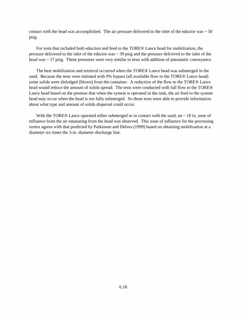
6.18
contact with the head was accomplished. The air pressure delivered to the inlet of the eductor was ~ 50
psig.
For tests that included both eduction and feed to the TORE® Lance head for mobilization, the
pressure delivered to the inlet of the eductor was ~ 39 psig and the pressure delivered to the inlet of the
head was ~ 17 psig. These pressures were very similar to tests with addition of pneumatic conveyance.
The best mobilization and retrieval occurred when the TORE® Lance head was submerged in the
sand. Because the tests were initiated with 0% bypass (all available flow to the TORE® Lance head)
some solids were dislodged (blown) from the container. A reduction of the flow to the TORE® Lance
head would reduce the amount of solids spread. The tests were conducted with full flow to the TORE®
Lance head based on the premise that when the system is operated in the tank, the air feed to the system
head may occur when the head is not fully submerged. So these tests were able to provide information
about what type and amount of solids dispersal could occur.
With the TORE® Lance operated either submerged or in contact with the sand, an ~ 18 in. zone of
influence from the air emanating from the head was observed. This zone of influence for the precessing
vortex agrees with that predicted by Parkinson and Delves (1999) based on obtaining mobilization at a
diameter six times the 3-in. diameter discharge line.
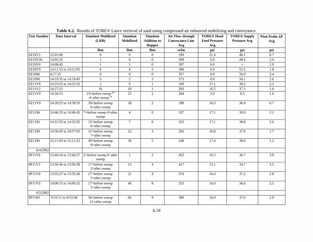
6.19
Table 6.2. Results of TORE® Lance retrieval of sand using compressed air enhanced mobilizing and conveyance.
Test Number Data Interval Simulant Mobilized
(LRB)
Simulant
Mobilized
Simulant
Addition to
Hopper
Air Flow through
Conveyance Line
Avg
TORE® Head
Feed Pressure
Avg
TORE® Supply
Pressure Avg
Pitot Probe P
Avg
lbm lbm lbm scfm psi psi psi
SZ10V2 12:01:06 0 0 0 189 21.4 46.1 0.7
SZ10V2b 14:05:35 1 0 0 399 0.0 49.4 2.9
SZ10V0 14:08:45 1 1 0 397 0.0 + 2.9
SZ10VS 14:11:55 to 14:12:05 6 4 5 306 0.0 52.5 1.8
SZ1090 4:17:25 0 0 0 357 0.0 56.0 2.4
SZ109S 14:19:35 to 14:19:45 5 2 3 373 0.0 50.1 2.6
SZ11V6 14:23:25 to 14:23:35 2 0 1 349 17.1 38.2 2.3
SZ11V2 14:27:15 10 10 1 293 16.5 37.5 1.6
SZ11V0 14:34:15 23=before sweep a0
4=after sweep b) 23 2 284 2.0 8.5 1.6
SZ11VS 14:39:25 to 14:39:35 39=before sweep
6=after sweep
18 2 188 16.3 36.9 0.7
SZ1196 14:46:35 to 14:46:45 7=before sweep 0=after
sweep
4 0 337 17.1 39.0 2.1
SZ1192 14:51:55 to 14:52:05 15=before sweep
0=after sweep
7 0 325 17.1 38.8 2.0
SZ1190 14:56:45 to 14:57:05 31=before sweep
7=after sweep
22 3 295 16.8 37.9 1.7
SZ119S 15:11:05 to 15:11:25 49=before sweep
9=after sweep
39 5 248 17.4 39.0 1.2
6/4/2002
SP11V6 13:44:16 to 13:44:27 2=before sweep 0=after
sweep
1 2 452 16.2 36.7 3.9
SP11V2 13:50:46 to 13:50:58 17=before sweep
2=after sweep
13 4 417 15.1 34.7 3.5
SP11V0 13:55:27 to 13:55:36 27=before sweep
5=after sweep
21 4 374 16.4 37.2 2.8
SP11VS 14:00:15 to 14:00:32 27=before sweep
5=after sweep
40 8 355 16.0 36.6 2.5
6/5/2002
SP116S 9:53:11 to 9:53:38 56=before sweep
12=after sweep
66 9 380 16.0 37.0 2.9
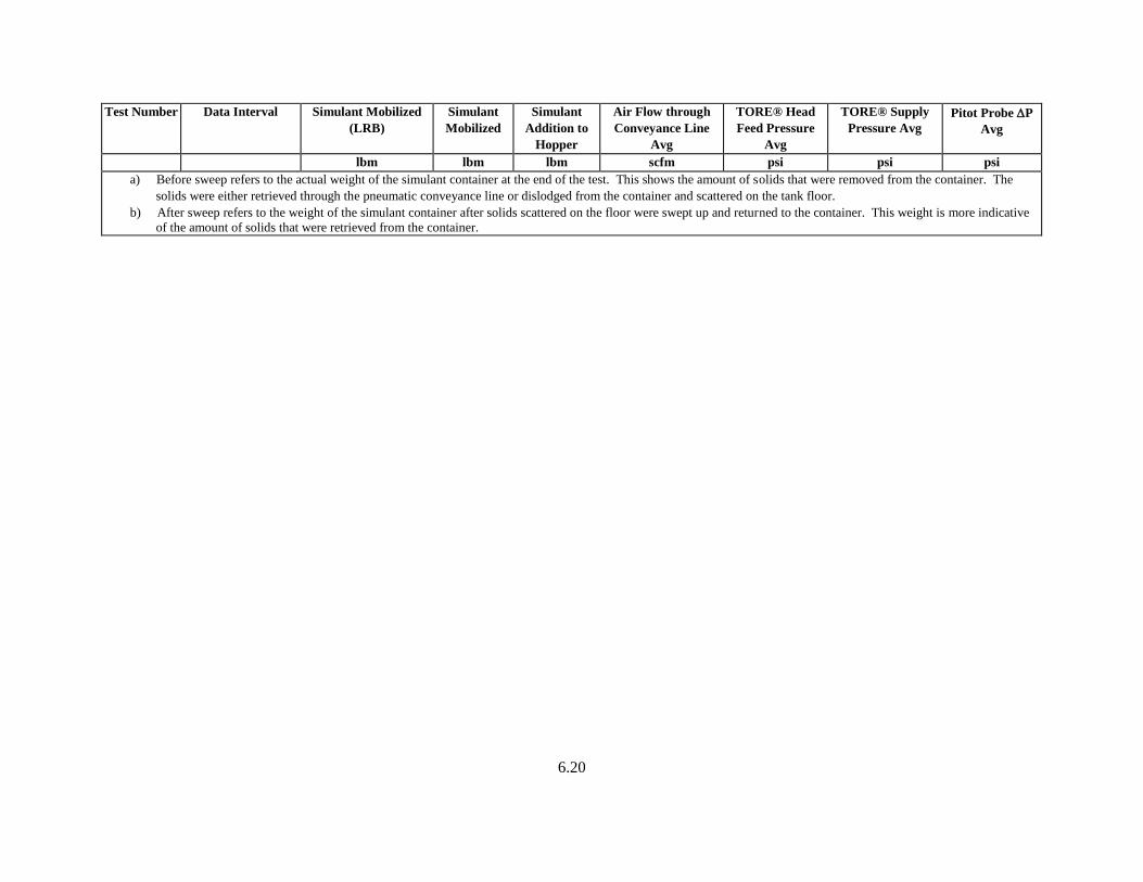
6.20
Test Number Data Interval Simulant Mobilized
(LRB)
Simulant
Mobilized
Simulant
Addition to
Hopper
Air Flow through
Conveyance Line
Avg
TORE® Head
Feed Pressure
Avg
TORE® Supply
Pressure Avg
Pitot Probe P
Avg
lbm lbm lbm scfm psi psi psi
a) Before sweep refers to the actual weight of the simulant container at the end of the test. This shows the amount of solids that were removed from the container. The
solids were either retrieved through the pneumatic conveyance line or dislodged from the container and scattered on the tank floor.
b) After sweep refers to the weight of the simulant container after solids scattered on the floor were swept up and returned to the container. This weight is more indicative
of the amount of solids that were retrieved from the container.
7.1
7.0 TORE® Lance Mobilization and Retrieval of Sludge
Sludge is one type of waste form that could be encountered during retrieval of radioactive waste from
underground storage tanks. Two types of sludge simulant were evaluated: an extremely hard sludge and
one developed to simulate some types of tank waste. All the TORE® Lance performance evaluations
were conducted using pneumatic conveyance to assist retrieval. The tests did vary the mobilizing fluid.
Tests were conducted using 100% compressed air, 100% pressurized water, and a mix of air with addition
of ~ 6 gpm water.
7.1 Sludge Test Matrix
The test series to evaluate dislodging of sludge was expanded to include using three types of
mobilizing fluids: 100% air, 100% water, and a mixture of mostly air with ~ 6 gpm water addition. To
identify each test a unique test number was developed. The components of this number were defined in
Section 4.5. The tests were conducted in three parts.
To evaluate the dislodging and retrieval of extremely strong sludge simulant. Selected tests
were conducted with either compressed air as the mobilizing and eductor fluid or pressurized
water as the mobilizing and eductor fluid to enhance the pneumatic conveyance. These tests
document evaluations of TORE® Lance ability to dislodge and retrieve a sludge type
simulant that is much stronger than anticipated to be found in the waste tanks.
To evaluate dislodging of sludge simulant using pressurized water through the TORE®
Lance head to mobilize the sludge and through the TORE® Lance eductor assembly to
complement pneumatic conveyance. These tests evaluate the ability of the TORE® Lance to
dislodge and mobilize a more typical sludge simulant using water for dislodging and
eduction. These tests also show how 100% water dislodging and eduction can be coupled
with pneumatic conveyance.
To evaluate the transport of solids through the TORE® Lance assembly to the conveyance
hopper using a combination of pressurized water through the TORE® Lance head to
mobilize the solids and through the TORE® Lance assembly in conjunction with pneumatic
conveyance. These tests show how a combination of compressed air and pressurized water
dislodging and eduction can be coupled with pneumatic conveyance.
The test matrix is listed in Table 7.1.
Table 7.1. Test matrix for evaluation of TORE® Lance mobilizing and retrieval of sludge.
Test
Number
Simulant Conveying Fluid Dis-
lodging
Fluid
Head
Feed
Orien-
tation
Stand-off
Distance
Objective To evaluate the dislodging and retrieval of extremely strong sludge simulant. Selected tests
were conducted with either compressed air as the mobilizing and eductor fluid or
pressurized water as the mobilizing and eductor fluid to enhance the pneumatic conveyance
KP11V0 Strong
kaolin
Air: pneumatic conveyance Air Air Vertical 0 in.
KP11VS Strong
kaolin
Air: pneumatic conveyance Air Air Vertical Submerged 6 in.
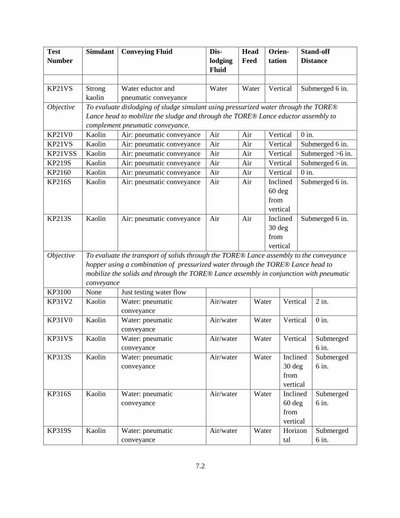
7.2
Test
Number
Simulant Conveying Fluid Dis-
lodging
Fluid
Head
Feed
Orien-
tation
Stand-off
Distance
KP21VS Strong
kaolin
Water eductor and
pneumatic conveyance
Water Water Vertical Submerged 6 in.
Objective To evaluate dislodging of sludge simulant using pressurized water through the TORE®
Lance head to mobilize the sludge and through the TORE® Lance eductor assembly to
complement pneumatic conveyance.
KP21V0 Kaolin Air: pneumatic conveyance Air Air Vertical 0 in.
KP21VS Kaolin Air: pneumatic conveyance Air Air Vertical Submerged 6 in.
KP21VSS Kaolin Air: pneumatic conveyance Air Air Vertical Submerged >6 in.
KP219S Kaolin Air: pneumatic conveyance Air Air Vertical Submerged 6 in.
KP2160 Kaolin Air: pneumatic conveyance Air Air Vertical 0 in.
KP216S Kaolin Air: pneumatic conveyance Air Air Inclined
60 deg
from
vertical
Submerged 6 in.
KP213S Kaolin Air: pneumatic conveyance Air Air Inclined
30 deg
from
vertical
Submerged 6 in.
Objective To evaluate the transport of solids through the TORE® Lance assembly to the conveyance
hopper using a combination of pressurized water through the TORE® Lance head to
mobilize the solids and through the TORE® Lance assembly in conjunction with pneumatic
conveyance
KP3100 None Just testing water flow
KP31V2 Kaolin Water: pneumatic
conveyance
Air/water Water Vertical 2 in.
KP31V0 Kaolin Water: pneumatic
conveyance
Air/water Water Vertical 0 in.
KP31VS Kaolin Water: pneumatic
conveyance
Air/water Water Vertical Submerged
6 in.
KP313S Kaolin Water: pneumatic
conveyance
Air/water Water Inclined
30 deg
from
vertical
Submerged
6 in.
KP316S Kaolin Water: pneumatic
conveyance
Air/water Water Inclined
60 deg
from
vertical
Submerged
6 in.
KP319S Kaolin Water: pneumatic
conveyance
Air/water Water Horizon
tal
Submerged
6 in.
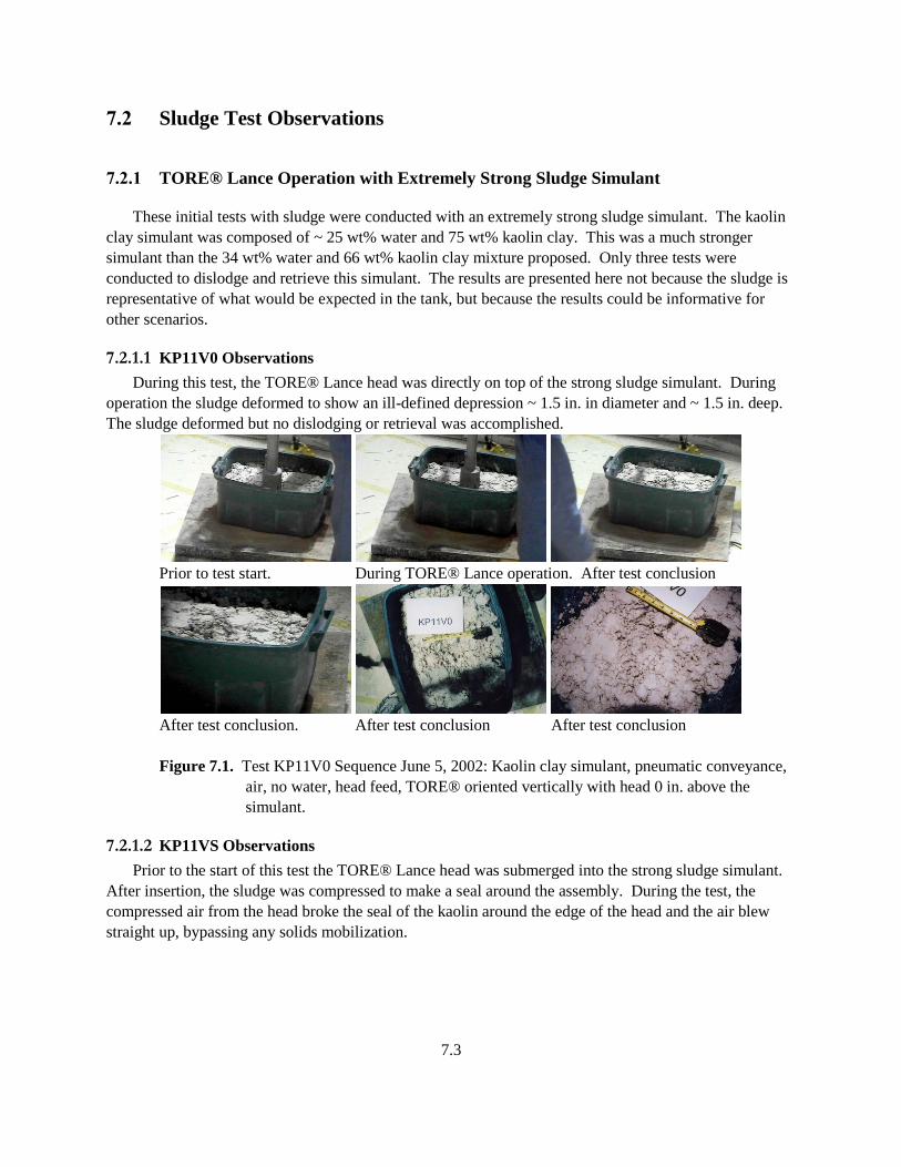
7.3
7.2 Sludge Test Observations
7.2.1 TORE® Lance Operation with Extremely Strong Sludge Simulant
These initial tests with sludge were conducted with an extremely strong sludge simulant. The kaolin
clay simulant was composed of ~ 25 wt% water and 75 wt% kaolin clay. This was a much stronger
simulant than the 34 wt% water and 66 wt% kaolin clay mixture proposed. Only three tests were
conducted to dislodge and retrieve this simulant. The results are presented here not because the sludge is
representative of what would be expected in the tank, but because the results could be informative for
other scenarios.
7.2.1.1 KP11V0 Observations
During this test, the TORE® Lance head was directly on top of the strong sludge simulant. During
operation the sludge deformed to show an ill-defined depression ~ 1.5 in. in diameter and ~ 1.5 in. deep.
The sludge deformed but no dislodging or retrieval was accomplished.
Prior to test start. During TORE® Lance operation. After test conclusion
After test conclusion. After test conclusion After test conclusion
Figure 7.1. Test KP11V0 Sequence June 5, 2002: Kaolin clay simulant, pneumatic conveyance,
air, no water, head feed, TORE® oriented vertically with head 0 in. above the
simulant.
7.2.1.2 KP11VS Observations
Prior to the start of this test the TORE® Lance head was submerged into the strong sludge simulant.
After insertion, the sludge was compressed to make a seal around the assembly. During the test, the
compressed air from the head broke the seal of the kaolin around the edge of the head and the air blew
straight up, bypassing any solids mobilization.
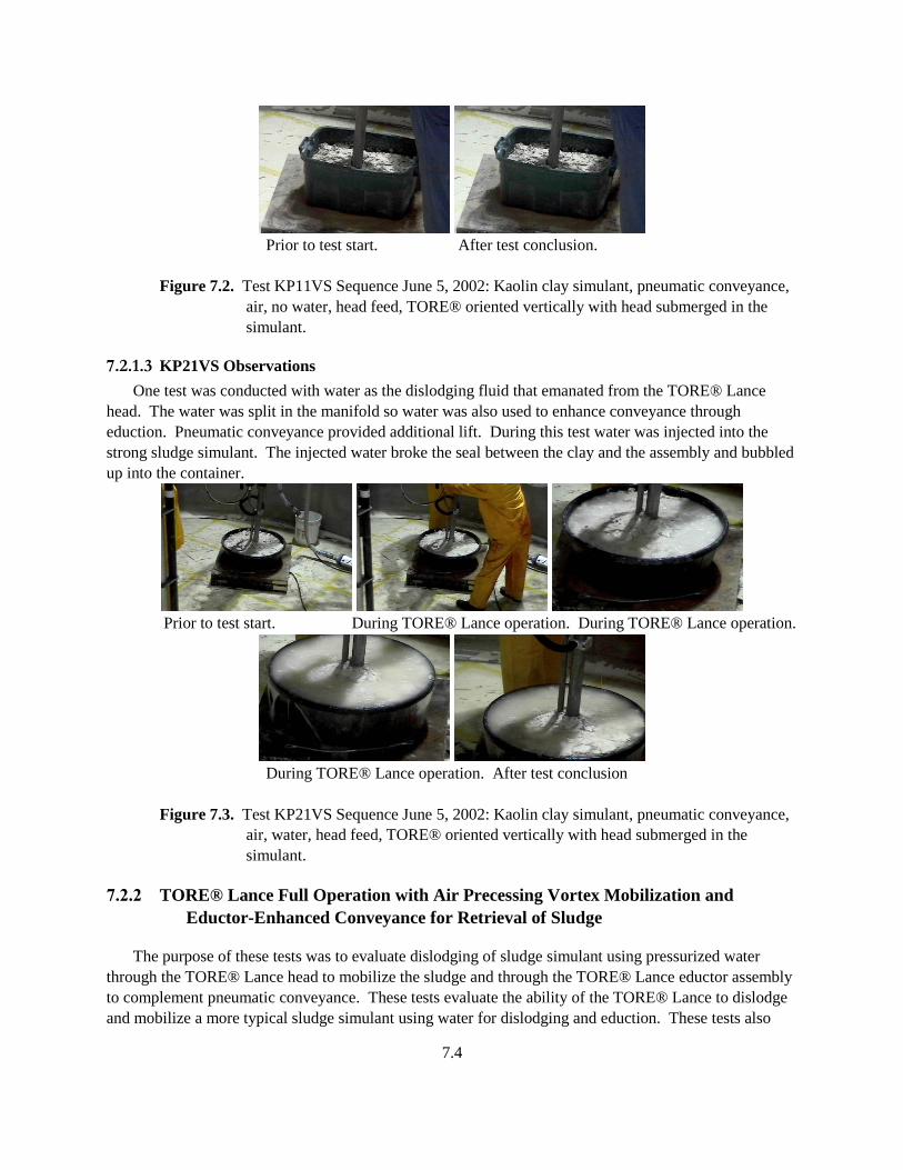
7.4
Prior to test start. After test conclusion.
Figure 7.2. Test KP11VS Sequence June 5, 2002: Kaolin clay simulant, pneumatic conveyance,
air, no water, head feed, TORE® oriented vertically with head submerged in the
simulant.
7.2.1.3 KP21VS Observations
One test was conducted with water as the dislodging fluid that emanated from the TORE® Lance
head. The water was split in the manifold so water was also used to enhance conveyance through
eduction. Pneumatic conveyance provided additional lift. During this test water was injected into the
strong sludge simulant. The injected water broke the seal between the clay and the assembly and bubbled
up into the container.
Prior to test start. During TORE® Lance operation. During TORE® Lance operation.
During TORE® Lance operation. After test conclusion
Figure 7.3. Test KP21VS Sequence June 5, 2002: Kaolin clay simulant, pneumatic conveyance,
air, water, head feed, TORE® oriented vertically with head submerged in the
simulant.
7.2.2 TORE® Lance Full Operation with Air Precessing Vortex Mobilization and
Eductor-Enhanced Conveyance for Retrieval of Sludge
The purpose of these tests was to evaluate dislodging of sludge simulant using pressurized water
through the TORE® Lance head to mobilize the sludge and through the TORE® Lance eductor assembly
to complement pneumatic conveyance. These tests evaluate the ability of the TORE® Lance to dislodge
and mobilize a more typical sludge simulant using water for dislodging and eduction. These tests also
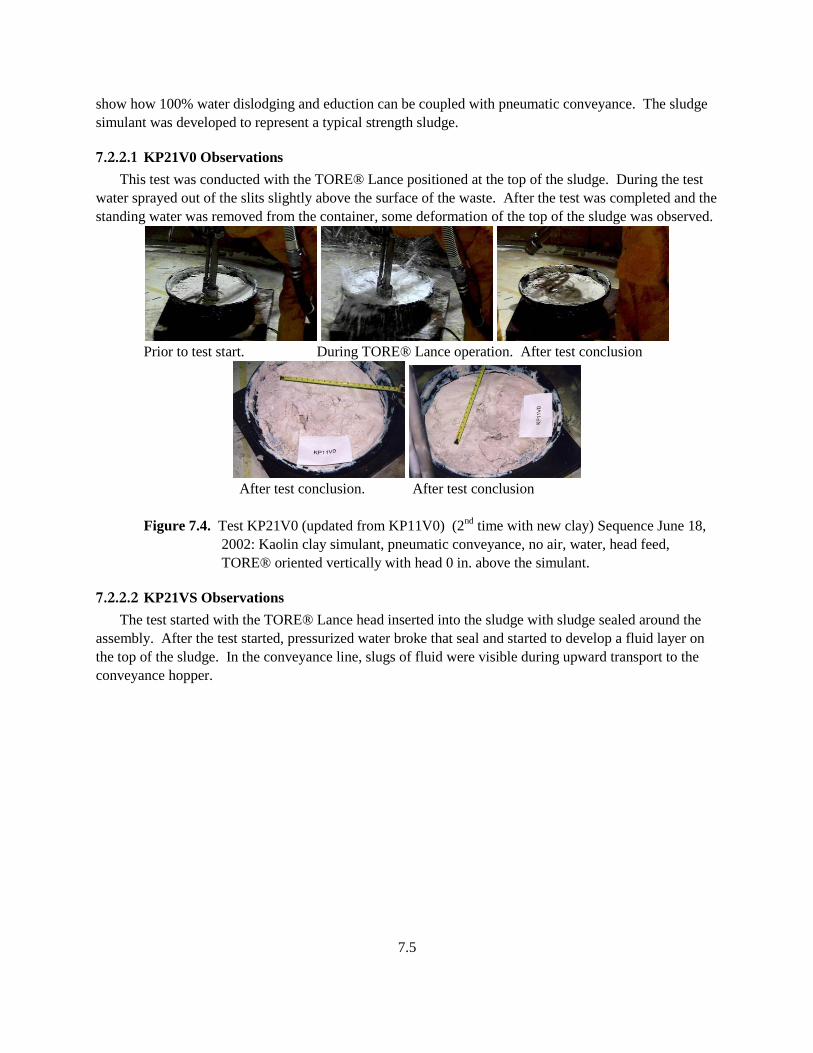
7.5
show how 100% water dislodging and eduction can be coupled with pneumatic conveyance. The sludge
simulant was developed to represent a typical strength sludge.
7.2.2.1 KP21V0 Observations
This test was conducted with the TORE® Lance positioned at the top of the sludge. During the test
water sprayed out of the slits slightly above the surface of the waste. After the test was completed and the
standing water was removed from the container, some deformation of the top of the sludge was observed.
Prior to test start. During TORE® Lance operation. After test conclusion
After test conclusion. After test conclusion
Figure 7.4. Test KP21V0 (updated from KP11V0) (2nd
time with new clay) Sequence June 18,
2002: Kaolin clay simulant, pneumatic conveyance, no air, water, head feed,
TORE® oriented vertically with head 0 in. above the simulant.
7.2.2.2 KP21VS Observations
The test started with the TORE® Lance head inserted into the sludge with sludge sealed around the
assembly. After the test started, pressurized water broke that seal and started to develop a fluid layer on
the top of the sludge. In the conveyance line, slugs of fluid were visible during upward transport to the
conveyance hopper.
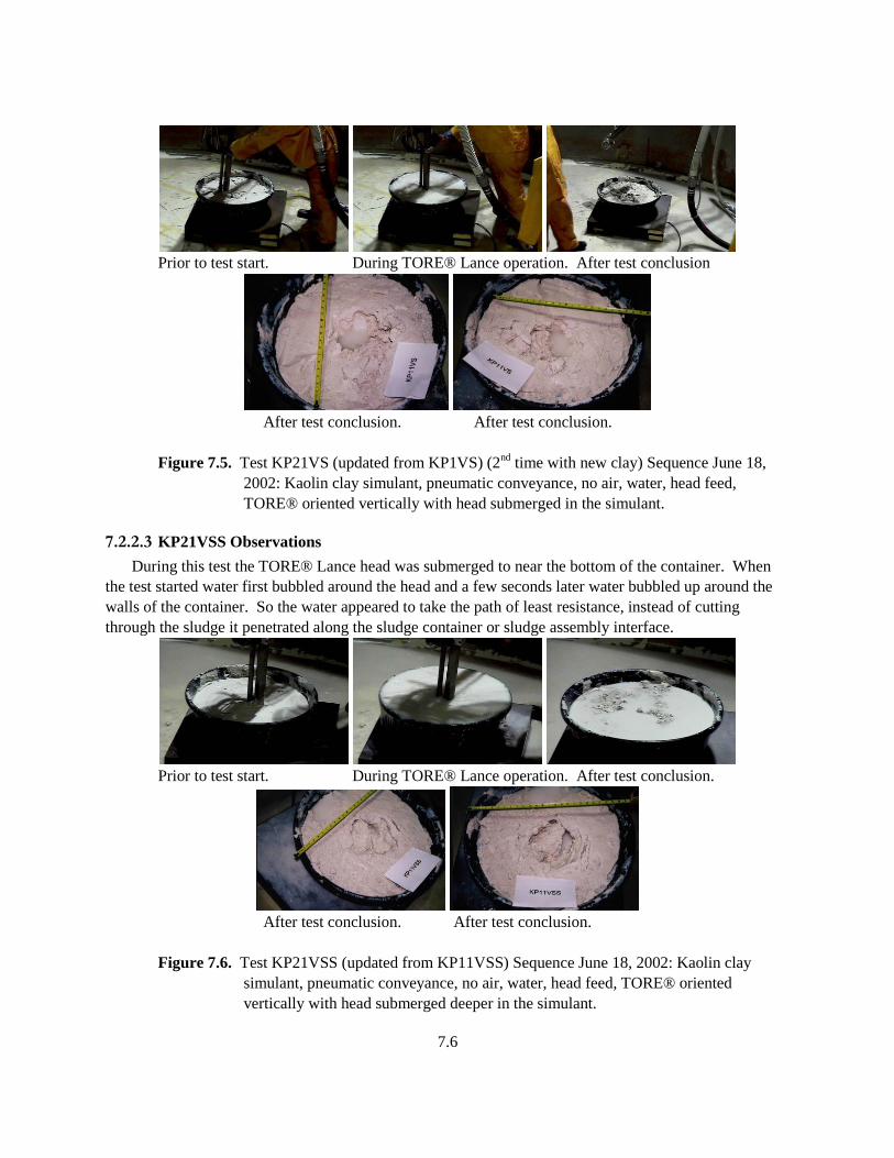
7.6
Prior to test start. During TORE® Lance operation. After test conclusion
After test conclusion. After test conclusion.
Figure 7.5. Test KP21VS (updated from KP1VS) (2nd
time with new clay) Sequence June 18,
2002: Kaolin clay simulant, pneumatic conveyance, no air, water, head feed,
TORE® oriented vertically with head submerged in the simulant.
7.2.2.3 KP21VSS Observations
During this test the TORE® Lance head was submerged to near the bottom of the container. When
the test started water first bubbled around the head and a few seconds later water bubbled up around the
walls of the container. So the water appeared to take the path of least resistance, instead of cutting
through the sludge it penetrated along the sludge container or sludge assembly interface.
Prior to test start. During TORE® Lance operation. After test conclusion.
After test conclusion. After test conclusion.
Figure 7.6. Test KP21VSS (updated from KP11VSS) Sequence June 18, 2002: Kaolin clay
simulant, pneumatic conveyance, no air, water, head feed, TORE® oriented
vertically with head submerged deeper in the simulant.
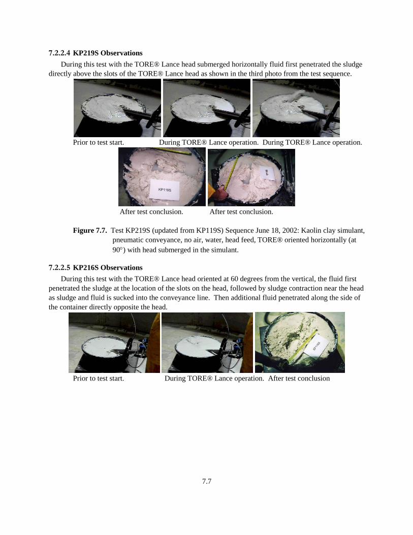
7.7
7.2.2.4 KP219S Observations
During this test with the TORE® Lance head submerged horizontally fluid first penetrated the sludge
directly above the slots of the TORE® Lance head as shown in the third photo from the test sequence.
Prior to test start. During TORE® Lance operation. During TORE® Lance operation.
After test conclusion. After test conclusion.
Figure 7.7. Test KP219S (updated from KP119S) Sequence June 18, 2002: Kaolin clay simulant,
pneumatic conveyance, no air, water, head feed, TORE® oriented horizontally (at
90) with head submerged in the simulant.
7.2.2.5 KP216S Observations
During this test with the TORE® Lance head oriented at 60 degrees from the vertical, the fluid first
penetrated the sludge at the location of the slots on the head, followed by sludge contraction near the head
as sludge and fluid is sucked into the conveyance line. Then additional fluid penetrated along the side of
the container directly opposite the head.
Prior to test start. During TORE® Lance operation. After test conclusion
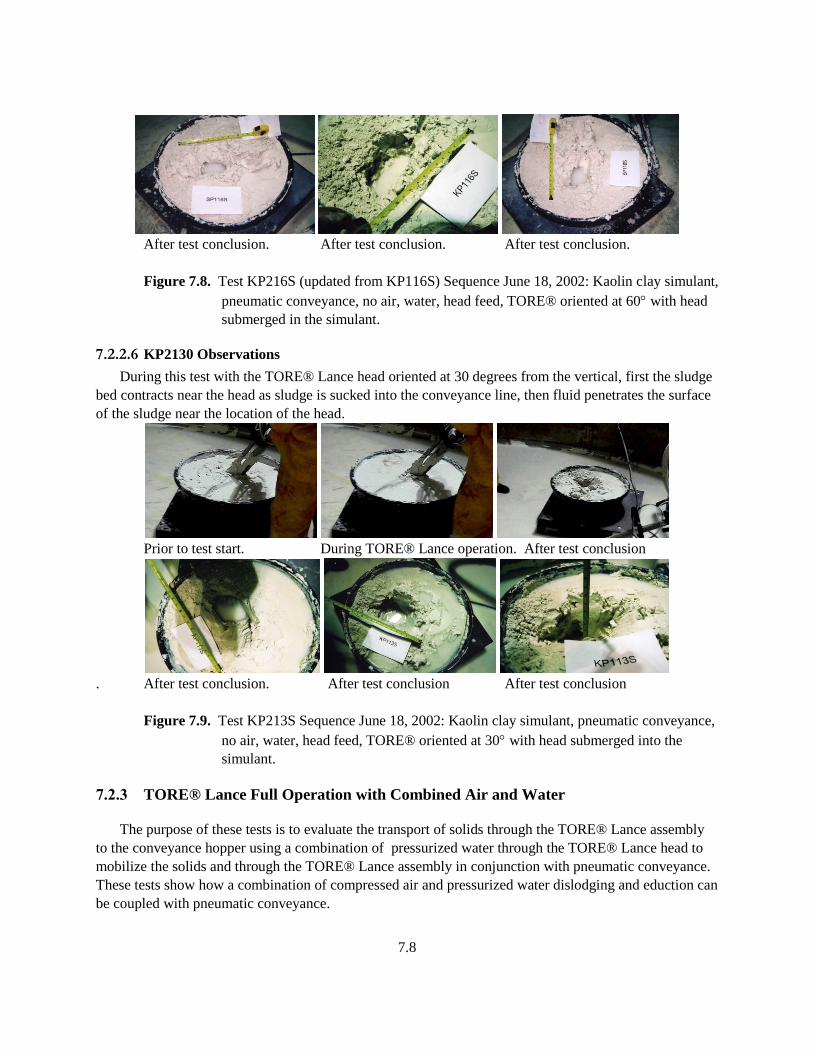
7.8
After test conclusion. After test conclusion. After test conclusion.
Figure 7.8. Test KP216S (updated from KP116S) Sequence June 18, 2002: Kaolin clay simulant,
pneumatic conveyance, no air, water, head feed, TORE® oriented at 60 with head
submerged in the simulant.
7.2.2.6 KP2130 Observations
During this test with the TORE® Lance head oriented at 30 degrees from the vertical, first the sludge
bed contracts near the head as sludge is sucked into the conveyance line, then fluid penetrates the surface
of the sludge near the location of the head.
Prior to test start. During TORE® Lance operation. After test conclusion
. After test conclusion. After test conclusion After test conclusion
Figure 7.9. Test KP213S Sequence June 18, 2002: Kaolin clay simulant, pneumatic conveyance,
no air, water, head feed, TORE® oriented at 30 with head submerged into the
simulant.
7.2.3 TORE® Lance Full Operation with Combined Air and Water
The purpose of these tests is to evaluate the transport of solids through the TORE® Lance assembly
to the conveyance hopper using a combination of pressurized water through the TORE® Lance head to
mobilize the solids and through the TORE® Lance assembly in conjunction with pneumatic conveyance.
These tests show how a combination of compressed air and pressurized water dislodging and eduction can
be coupled with pneumatic conveyance.
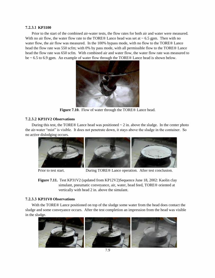
7.9
7.2.3.1 KP3100
Prior to the start of the combined air-water tests, the flow rates for both air and water were measured.
With no air flow, the water flow rate to the TORE® Lance head was set at ~ 6.5 gpm. Then with no
water flow, the air flow was measured. In the 100% bypass mode, with no flow to the TORE® Lance
head the flow rate was 550 scfm; with 0% by pass mode, with all permissible flow to the TORE® Lance
head the flow rate was 650 scfm. With combined air and water flow, the water flow rate was measured to
be ~ 6.5 to 6.9 gpm. An example of water flow through the TORE® Lance head is shown below.
Figure 7.10. Flow of water through the TORE® Lance head.
7.2.3.2 KP31V2 Observations
During this test, the TORE® Lance head was positioned ~ 2 in. above the sludge. In the center photo
the air-water “mist” is visible. It does not penetrate down, it stays above the sludge in the container. So
no active dislodging occurs.
Prior to test start. During TORE® Lance operation. After test conclusion.
Figure 7.11. Test KP31V2 (updated from KP12V2)Sequence June 18, 2002: Kaolin clay
simulant, pneumatic conveyance, air, water, head feed, TORE® oriented at
vertically with head 2 in. above the simulant.
7.2.3.3 KP31V0 Observations
With the TORE® Lance positioned on top of the sludge some water from the head does contact the
sludge and some conveyance occurs. After the test completion an impression from the head was visible
in the sludge.
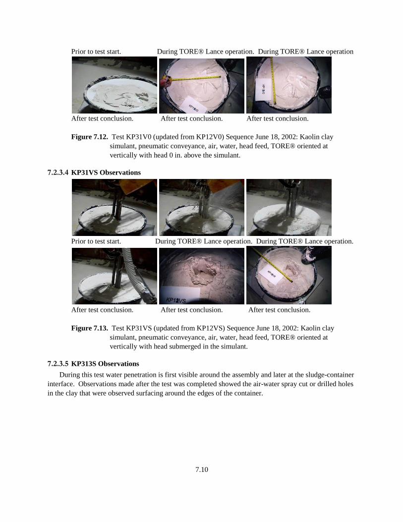
7.10
Prior to test start. During TORE® Lance operation. During TORE® Lance operation
After test conclusion. After test conclusion. After test conclusion.
Figure 7.12. Test KP31V0 (updated from KP12V0) Sequence June 18, 2002: Kaolin clay
simulant, pneumatic conveyance, air, water, head feed, TORE® oriented at
vertically with head 0 in. above the simulant.
7.2.3.4 KP31VS Observations
Prior to test start. During TORE® Lance operation. During TORE® Lance operation.
After test conclusion. After test conclusion. After test conclusion.
Figure 7.13. Test KP31VS (updated from KP12VS) Sequence June 18, 2002: Kaolin clay
simulant, pneumatic conveyance, air, water, head feed, TORE® oriented at
vertically with head submerged in the simulant.
7.2.3.5 KP313S Observations
During this test water penetration is first visible around the assembly and later at the sludge-container
interface. Observations made after the test was completed showed the air-water spray cut or drilled holes
in the clay that were observed surfacing around the edges of the container.
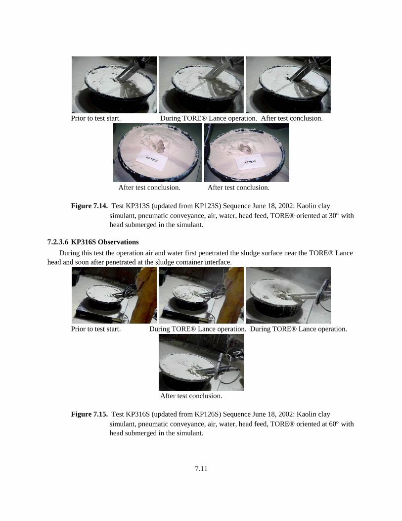
7.11
Prior to test start. During TORE® Lance operation. After test conclusion.
After test conclusion. After test conclusion.
Figure 7.14. Test KP313S (updated from KP123S) Sequence June 18, 2002: Kaolin clay
simulant, pneumatic conveyance, air, water, head feed, TORE® oriented at 30 with
head submerged in the simulant.
7.2.3.6 KP316S Observations
During this test the operation air and water first penetrated the sludge surface near the TORE® Lance
head and soon after penetrated at the sludge container interface.
Prior to test start. During TORE® Lance operation. During TORE® Lance operation.
After test conclusion.
Figure 7.15. Test KP316S (updated from KP126S) Sequence June 18, 2002: Kaolin clay
simulant, pneumatic conveyance, air, water, head feed, TORE® oriented at 60 with
head submerged in the simulant.

7.12
7.2.3.7 KP319S Observations
During this test the air and water penetrated through the top of the sludge and around the perimeter of
the container almost simultaneously.
Prior to test start. During TORE® Lance operation. After test conclusion
After test conclusion. After test conclusion After test conclusion
Figure 7.16. Test KP319S Sequence June 18, 2002: Kaolin clay simulant, pneumatic
conveyance, air, water, head feed, TORE® oriented at horizontally (at 90) with
head submerged in the simulant.
7.3 Sludge Test Results
The kaolin test results showed significantly different behavior based on the fluid used for
mobilization: air, water, or an air-water combination.
The air took the path of least resistance, channeling between the sludge and the assembly or
the sludge and container. After this occurred no additional dislodging of the sludge was
observed.
The water also took the path of least resistance; however, some dislodging was observed.
The air-water combination was able to cut small-diameter channels through the sludge to
form a radial cut pattern. Additional dislodging of the sludge occurred along these paths.
When coupled with pneumatic conveyance and eduction the most effective method for sludge
dislodging and retrieval turned out to be the air-water combination. The air-water stream was able to
penetrate through the sludge; the assist to pneumatic conveyance provided by the compressed air (with
some water) enhanced the potential for some retrieval.
The water only dislodging stream provided quite a bit of additional water to be conveyed
pneumatically out of the tank. This configuration tended to overload the system retrieval capability and
water tended to pool up on the surface of the sludge. With a different retrieval approach or one designed
to handle this water flow, the approach may be more effective. The air only dislodging stream is not
recommended for dislodging and retrieval of sludge. Details of the test data are listed in Table 7.2.
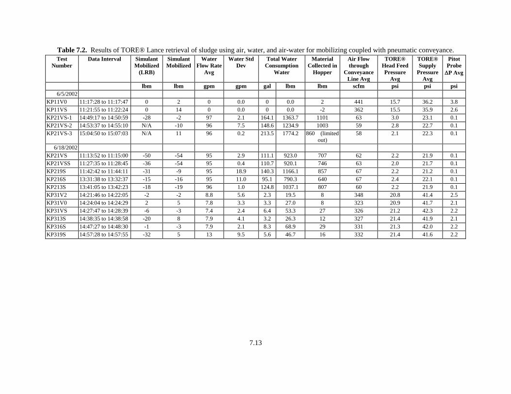
7.13
Table 7.2. Results of TORE® Lance retrieval of sludge using air, water, and air-water for mobilizing coupled with pneumatic conveyance.
Test
Number
Data Interval Simulant
Mobilized
(LRB)
Simulant
Mobilized
Water
Flow Rate
Avg
Water Std
Dev
Total Water
Consumption
Water
Material
Collected in
Hopper
Air Flow
through
Conveyance
Line Avg
TORE®
Head Feed
Pressure
Avg
TORE®
Supply
Pressure
Avg
Pitot
Probe
P Avg
lbm lbm gpm gpm gal lbm lbm scfm psi psi psi
6/5/2002
KP11V0 11:17:28 to 11:17:47 0 2 0 0.0 0 0.0 2 441 15.7 36.2 3.8
KP11VS 11:21:55 to 11:22:24 0 14 0 0.0 0 0.0 -2 362 15.5 35.9 2.6
KP21VS-1 14:49:17 to 14:50:59 -28 -2 97 2.1 164.1 1363.7 1101 63 3.0 23.1 0.1
KP21VS-2 14:53:37 to 14:55:10 N/A -10 96 7.5 148.6 1234.9 1003 59 2.8 22.7 0.1
KP21VS-3 15:04:50 to 15:07:03 N/A 11 96 0.2 213.5 1774.2 860 (limited
out)
58 2.1 22.3 0.1
6/18/2002
KP21VS 11:13:52 to 11:15:00 -50 -54 95 2.9 111.1 923.0 707 62 2.2 21.9 0.1
KP21VSS 11:27:35 to 11:28:45 -36 -54 95 0.4 110.7 920.1 746 63 2.0 21.7 0.1
KP219S 11:42:42 to 11:44:11 -31 -9 95 18.9 140.3 1166.1 857 67 2.2 21.2 0.1
KP216S 13:31:38 to 13:32:37 -15 -16 95 11.0 95.1 790.3 640 67 2.4 22.1 0.1
KP213S 13:41:05 to 13:42:23 -18 -19 96 1.0 124.8 1037.1 807 60 2.2 21.9 0.1
KP31V2 14:21:46 to 14:22:05 -2 -2 8.8 5.6 2.3 19.5 8 348 20.8 41.4 2.5
KP31V0 14:24:04 to 14:24:29 2 5 7.8 3.3 3.3 27.0 8 323 20.9 41.7 2.1
KP31VS 14:27:47 to 14:28:39 -6 -3 7.4 2.4 6.4 53.3 27 326 21.2 42.3 2.2
KP313S 14:38:35 to 14:38:58 -20 8 7.9 4.1 3.2 26.3 12 327 21.4 41.9 2.1
KP316S 14:47:27 to 14:48:30 -1 -3 7.9 2.1 8.3 68.9 29 331 21.3 42.0 2.2
KP319S 14:57:28 to 14:57:55 -32 5 13 9.5 5.6 46.7 16 332 21.4 41.6 2.2

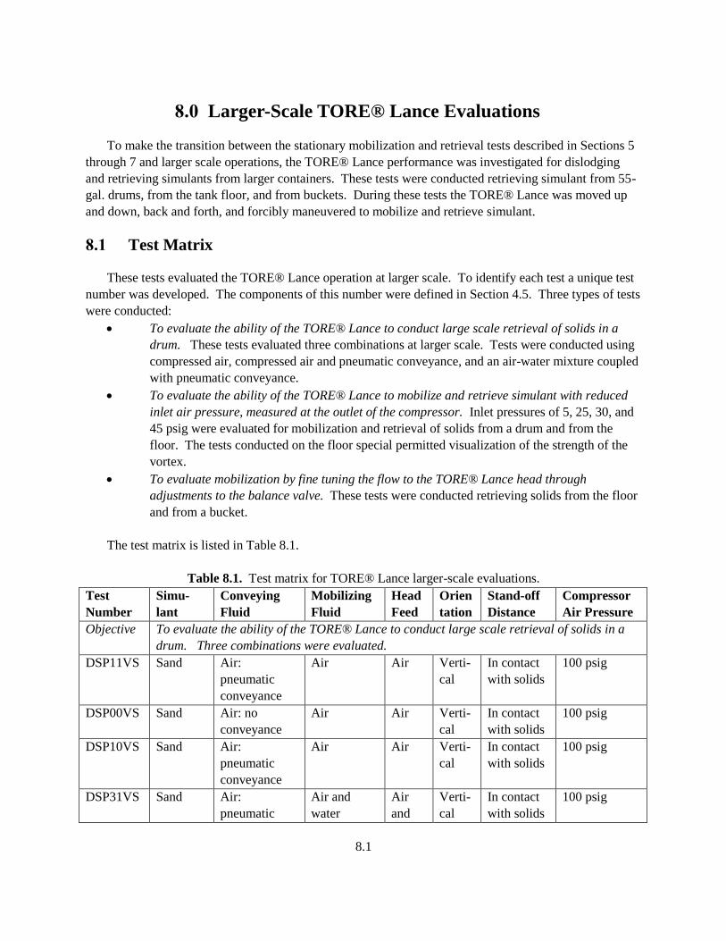
8.1
8.0 Larger-Scale TORE® Lance Evaluations
To make the transition between the stationary mobilization and retrieval tests described in Sections 5
through 7 and larger scale operations, the TORE® Lance performance was investigated for dislodging
and retrieving simulants from larger containers. These tests were conducted retrieving simulant from 55-
gal. drums, from the tank floor, and from buckets. During these tests the TORE® Lance was moved up
and down, back and forth, and forcibly maneuvered to mobilize and retrieve simulant.
8.1 Test Matrix
These tests evaluated the TORE® Lance operation at larger scale. To identify each test a unique test
number was developed. The components of this number were defined in Section 4.5. Three types of tests
were conducted:
To evaluate the ability of the TORE® Lance to conduct large scale retrieval of solids in a
drum. These tests evaluated three combinations at larger scale. Tests were conducted using
compressed air, compressed air and pneumatic conveyance, and an air-water mixture coupled
with pneumatic conveyance.
To evaluate the ability of the TORE® Lance to mobilize and retrieve simulant with reduced
inlet air pressure, measured at the outlet of the compressor. Inlet pressures of 5, 25, 30, and
45 psig were evaluated for mobilization and retrieval of solids from a drum and from the
floor. The tests conducted on the floor special permitted visualization of the strength of the
vortex.
To evaluate mobilization by fine tuning the flow to the TORE® Lance head through
adjustments to the balance valve. These tests were conducted retrieving solids from the floor
and from a bucket.
The test matrix is listed in Table 8.1.
Table 8.1. Test matrix for TORE® Lance larger-scale evaluations.
Test
Number
Simu-
lant
Conveying
Fluid
Mobilizing
Fluid
Head
Feed
Orien
tation
Stand-off
Distance
Compressor
Air Pressure
Objective To evaluate the ability of the TORE® Lance to conduct large scale retrieval of solids in a
drum. Three combinations were evaluated.
DSP11VS Sand Air:
pneumatic
conveyance
Air Air Verti-
cal
In contact
with solids
100 psig
DSP00VS Sand Air: no
conveyance
Air Air Verti-
cal
In contact
with solids
100 psig
DSP10VS Sand Air:
pneumatic
conveyance
Air Air Verti-
cal
In contact
with solids
100 psig
DSP31VS Sand Air:
pneumatic
Air and
water
Air
and
Verti-
cal
In contact
with solids
100 psig
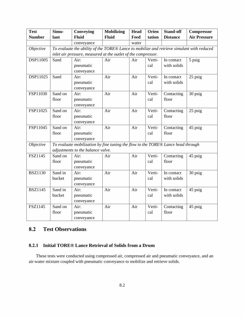
8.2
Test
Number
Simu-
lant
Conveying
Fluid
Mobilizing
Fluid
Head
Feed
Orien
tation
Stand-off
Distance
Compressor
Air Pressure
conveyance water
Objective To evaluate the ability of the TORE® Lance to mobilize and retrieve simulant with reduced
inlet air pressure, measured at the outlet of the compressor.
DSP11005 Sand Air:
pneumatic
conveyance
Air Air Verti-
cal
In contact
with solids
5 psig
DSP11025 Sand Air:
pneumatic
conveyance
Air Air Verti-
cal
In contact
with solids
25 psig
FSP11030 Sand on
floor
Air:
pneumatic
conveyance
Air Air Verti-
cal
Contacting
floor
30 psig
FSP11025 Sand on
floor
Air:
pneumatic
conveyance
Air Air Verti-
cal
Contacting
floor
25 psig
FSP11045 Sand on
floor
Air:
pneumatic
conveyance
Air Air Verti-
cal
Contacting
floor
45 psig
Objective To evaluate mobilization by fine tuning the flow to the TORE® Lance head through
adjustments to the balance valve.
FSZ1145 Sand on
floor
Air:
pneumatic
conveyance
Air Air Verti-
cal
Contacting
floor
45 psig
BSZ1130 Sand in
bucket
Air:
pneumatic
conveyance
Air Air Verti-
cal
In contact
with solids
30 psig
BSZ1145 Sand in
bucket
Air:
pneumatic
conveyance
Air Air Verti-
cal
In contact
with solids
45 psig
FSZ1145 Sand on
floor
Air:
pneumatic
conveyance
Air Air Verti-
cal
Contacting
floor
45 psig
8.2 Test Observations
8.2.1 Initial TORE® Lance Retrieval of Solids from a Drum
These tests were conducted using compressed air, compressed air and pneumatic conveyance, and an
air-water mixture coupled with pneumatic conveyance to mobilize and retrieve solids.
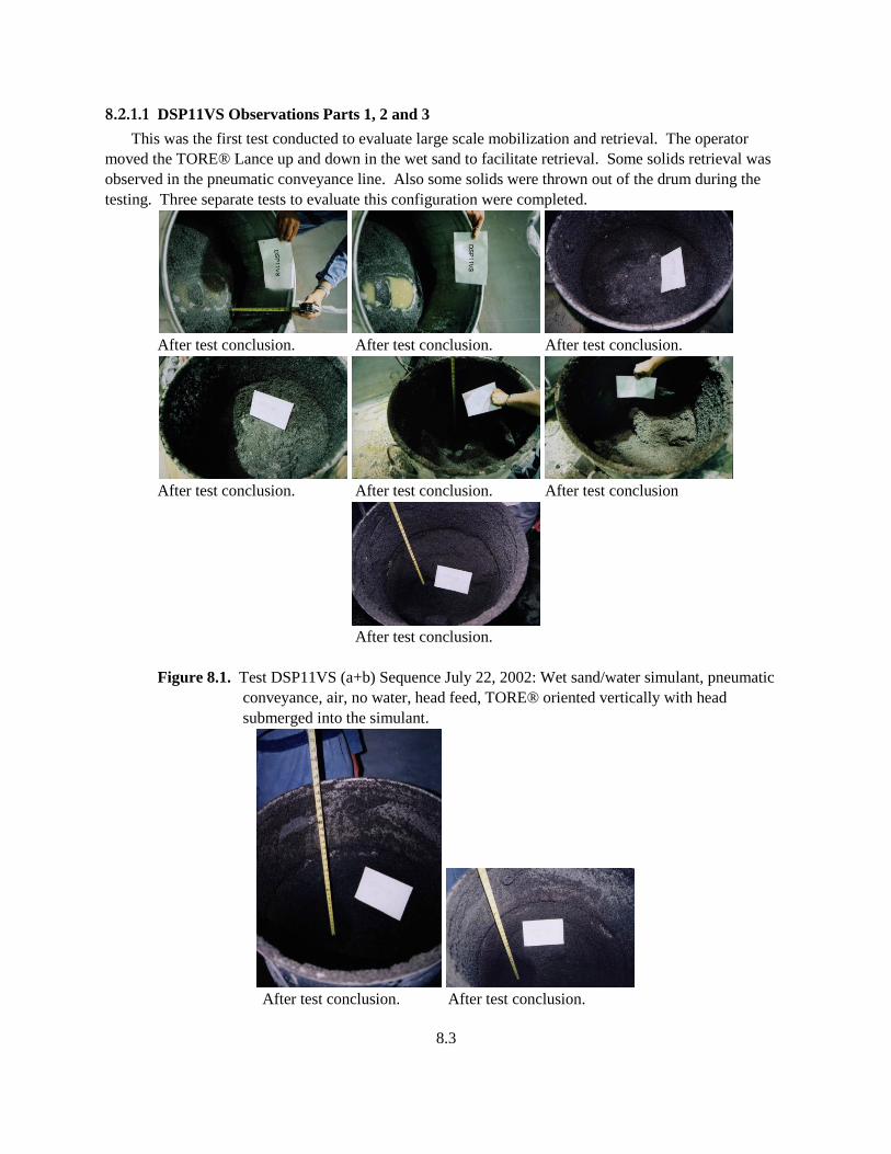
8.3
8.2.1.1 DSP11VS Observations Parts 1, 2 and 3
This was the first test conducted to evaluate large scale mobilization and retrieval. The operator
moved the TORE® Lance up and down in the wet sand to facilitate retrieval. Some solids retrieval was
observed in the pneumatic conveyance line. Also some solids were thrown out of the drum during the
testing. Three separate tests to evaluate this configuration were completed.
After test conclusion. After test conclusion. After test conclusion.
After test conclusion. After test conclusion. After test conclusion
After test conclusion.
Figure 8.1. Test DSP11VS (a+b) Sequence July 22, 2002: Wet sand/water simulant, pneumatic
conveyance, air, no water, head feed, TORE® oriented vertically with head
submerged into the simulant.
After test conclusion. After test conclusion.
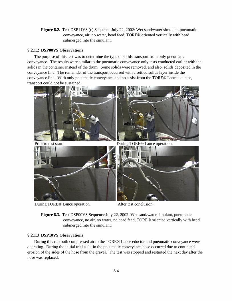
8.4
Figure 8.2. Test DSP11VS (c) Sequence July 22, 2002: Wet sand/water simulant, pneumatic
conveyance, air, no water, head feed, TORE® oriented vertically with head
submerged into the simulant.
8.2.1.2 DSP00VS Observations
The purpose of this test was to determine the type of solids transport from only pneumatic
conveyance. The results were similar to the pneumatic conveyance only tests conducted earlier with the
solids in the container instead of the drum. Some solids were removed, and also, solids deposited in the
conveyance line. The remainder of the transport occurred with a settled solids layer inside the
conveyance line. With only pneumatic conveyance and no assist from the TORE® Lance eductor,
transport could not be sustained.
Prior to test start. During TORE® Lance operation.
During TORE® Lance operation. After test conclusion.
Figure 8.3. Test DSP00VS Sequence July 22, 2002: Wet sand/water simulant, pneumatic
conveyance, no air, no water, no head feed, TORE® oriented vertically with head
submerged into the simulant.
8.2.1.3 DSP10VS Observations
During this run both compressed air to the TORE® Lance eductor and pneumatic conveyance were
operating. During the initial trial a slit in the pneumatic conveyance hose occurred due to continued
erosion of the sides of the hose from the gravel. The test was stopped and restarted the next day after the
hose was replaced.
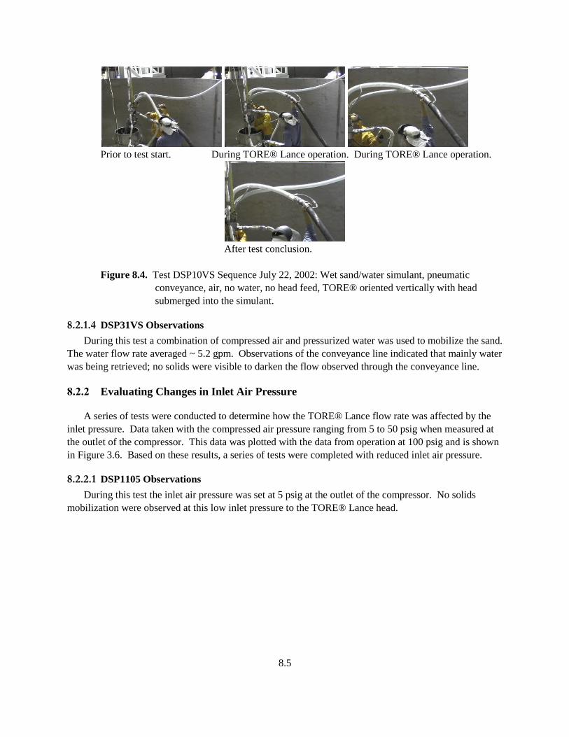
8.5
Prior to test start. During TORE® Lance operation. During TORE® Lance operation.
After test conclusion.
Figure 8.4. Test DSP10VS Sequence July 22, 2002: Wet sand/water simulant, pneumatic
conveyance, air, no water, no head feed, TORE® oriented vertically with head
submerged into the simulant.
8.2.1.4 DSP31VS Observations
During this test a combination of compressed air and pressurized water was used to mobilize the sand.
The water flow rate averaged ~ 5.2 gpm. Observations of the conveyance line indicated that mainly water
was being retrieved; no solids were visible to darken the flow observed through the conveyance line.
8.2.2 Evaluating Changes in Inlet Air Pressure
A series of tests were conducted to determine how the TORE® Lance flow rate was affected by the
inlet pressure. Data taken with the compressed air pressure ranging from 5 to 50 psig when measured at
the outlet of the compressor. This data was plotted with the data from operation at 100 psig and is shown
in Figure 3.6. Based on these results, a series of tests were completed with reduced inlet air pressure.
8.2.2.1 DSP1105 Observations
During this test the inlet air pressure was set at 5 psig at the outlet of the compressor. No solids
mobilization were observed at this low inlet pressure to the TORE® Lance head.
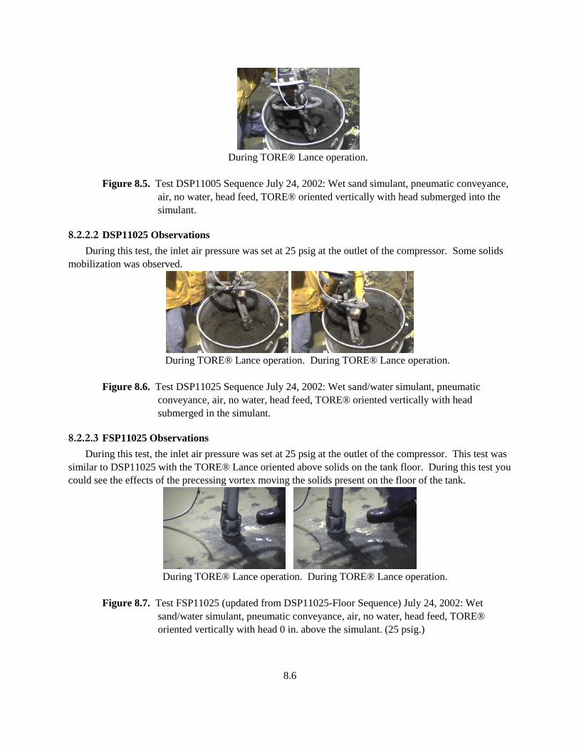
8.6
During TORE® Lance operation.
Figure 8.5. Test DSP11005 Sequence July 24, 2002: Wet sand simulant, pneumatic conveyance,
air, no water, head feed, TORE® oriented vertically with head submerged into the
simulant.
8.2.2.2 DSP11025 Observations
During this test, the inlet air pressure was set at 25 psig at the outlet of the compressor. Some solids
mobilization was observed.
During TORE® Lance operation. During TORE® Lance operation.
Figure 8.6. Test DSP11025 Sequence July 24, 2002: Wet sand/water simulant, pneumatic
conveyance, air, no water, head feed, TORE® oriented vertically with head
submerged in the simulant.
8.2.2.3 FSP11025 Observations
During this test, the inlet air pressure was set at 25 psig at the outlet of the compressor. This test was
similar to DSP11025 with the TORE® Lance oriented above solids on the tank floor. During this test you
could see the effects of the precessing vortex moving the solids present on the floor of the tank.
During TORE® Lance operation. During TORE® Lance operation.
Figure 8.7. Test FSP11025 (updated from DSP11025-Floor Sequence) July 24, 2002: Wet
sand/water simulant, pneumatic conveyance, air, no water, head feed, TORE®
oriented vertically with head 0 in. above the simulant. (25 psig.)
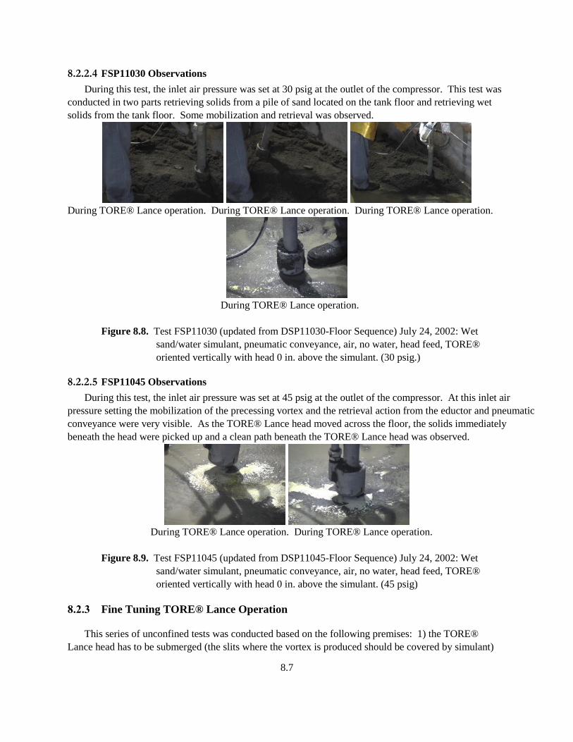
8.7
8.2.2.4 FSP11030 Observations
During this test, the inlet air pressure was set at 30 psig at the outlet of the compressor. This test was
conducted in two parts retrieving solids from a pile of sand located on the tank floor and retrieving wet
solids from the tank floor. Some mobilization and retrieval was observed.
During TORE® Lance operation. During TORE® Lance operation. During TORE® Lance operation.
During TORE® Lance operation.
Figure 8.8. Test FSP11030 (updated from DSP11030-Floor Sequence) July 24, 2002: Wet
sand/water simulant, pneumatic conveyance, air, no water, head feed, TORE®
oriented vertically with head 0 in. above the simulant. (30 psig.)
8.2.2.5 FSP11045 Observations
During this test, the inlet air pressure was set at 45 psig at the outlet of the compressor. At this inlet air
pressure setting the mobilization of the precessing vortex and the retrieval action from the eductor and pneumatic
conveyance were very visible. As the TORE® Lance head moved across the floor, the solids immediately
beneath the head were picked up and a clean path beneath the TORE® Lance head was observed.
During TORE® Lance operation. During TORE® Lance operation.
Figure 8.9. Test FSP11045 (updated from DSP11045-Floor Sequence) July 24, 2002: Wet
sand/water simulant, pneumatic conveyance, air, no water, head feed, TORE®
oriented vertically with head 0 in. above the simulant. (45 psig)
8.2.3 Fine Tuning TORE® Lance Operation
This series of unconfined tests was conducted based on the following premises: 1) the TORE®
Lance head has to be submerged (the slits where the vortex is produced should be covered by simulant)
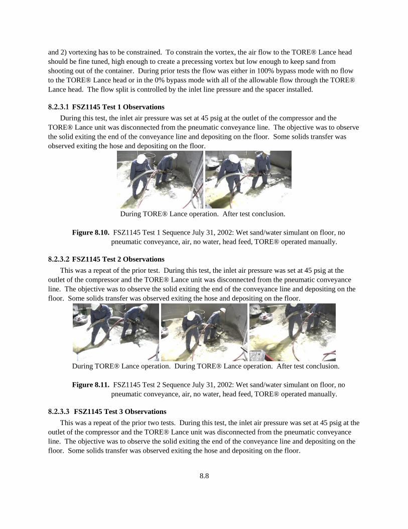
8.8
and 2) vortexing has to be constrained. To constrain the vortex, the air flow to the TORE® Lance head
should be fine tuned, high enough to create a precessing vortex but low enough to keep sand from
shooting out of the container. During prior tests the flow was either in 100% bypass mode with no flow
to the TORE® Lance head or in the 0% bypass mode with all of the allowable flow through the TORE®
Lance head. The flow split is controlled by the inlet line pressure and the spacer installed.
8.2.3.1 FSZ1145 Test 1 Observations
During this test, the inlet air pressure was set at 45 psig at the outlet of the compressor and the
TORE® Lance unit was disconnected from the pneumatic conveyance line. The objective was to observe
the solid exiting the end of the conveyance line and depositing on the floor. Some solids transfer was
observed exiting the hose and depositing on the floor.
During TORE® Lance operation. After test conclusion.
Figure 8.10. FSZ1145 Test 1 Sequence July 31, 2002: Wet sand/water simulant on floor, no
pneumatic conveyance, air, no water, head feed, TORE® operated manually.
8.2.3.2 FSZ1145 Test 2 Observations
This was a repeat of the prior test. During this test, the inlet air pressure was set at 45 psig at the
outlet of the compressor and the TORE® Lance unit was disconnected from the pneumatic conveyance
line. The objective was to observe the solid exiting the end of the conveyance line and depositing on the
floor. Some solids transfer was observed exiting the hose and depositing on the floor.
During TORE® Lance operation. During TORE® Lance operation. After test conclusion.
Figure 8.11. FSZ1145 Test 2 Sequence July 31, 2002: Wet sand/water simulant on floor, no
pneumatic conveyance, air, no water, head feed, TORE® operated manually.
8.2.3.3 FSZ1145 Test 3 Observations
This was a repeat of the prior two tests. During this test, the inlet air pressure was set at 45 psig at the
outlet of the compressor and the TORE® Lance unit was disconnected from the pneumatic conveyance
line. The objective was to observe the solid exiting the end of the conveyance line and depositing on the
floor. Some solids transfer was observed exiting the hose and depositing on the floor.
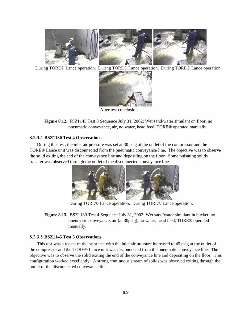
8.9
During TORE® Lance operation. During TORE® Lance operation. During TORE® Lance operation.
After test conclusion.
Figure 8.12. FSZ1145 Test 3 Sequence July 31, 2002: Wet sand/water simulant on floor, no
pneumatic conveyance, air, no water, head feed, TORE® operated manually.
8.2.3.4 BSZ1130 Test 4 Observations
During this test, the inlet air pressure was set at 30 psig at the outlet of the compressor and the
TORE® Lance unit was disconnected from the pneumatic conveyance line. The objective was to observe
the solid exiting the end of the conveyance line and depositing on the floor. Some pulsating solids
transfer was observed through the outlet of the disconnected conveyance line.
During TORE® Lance operation. During TORE® Lance operation.
Figure 8.13. BSZ1130 Test 4 Sequence July 31, 2002: Wet sand/water simulant in bucket, no
pneumatic conveyance, air (at 30psig), no water, head feed, TORE® operated
manually.
8.2.3.5 BSZ1145 Test 5 Observations
This test was a repeat of the prior test with the inlet air pressure increased to 45 psig at the outlet of
the compressor and the TORE® Lance unit was disconnected from the pneumatic conveyance line. The
objective was to observe the solid exiting the end of the conveyance line and depositing on the floor. This
configuration worked excellently. A strong continuous stream of solids was observed exiting through the
outlet of the disconnected conveyance line.
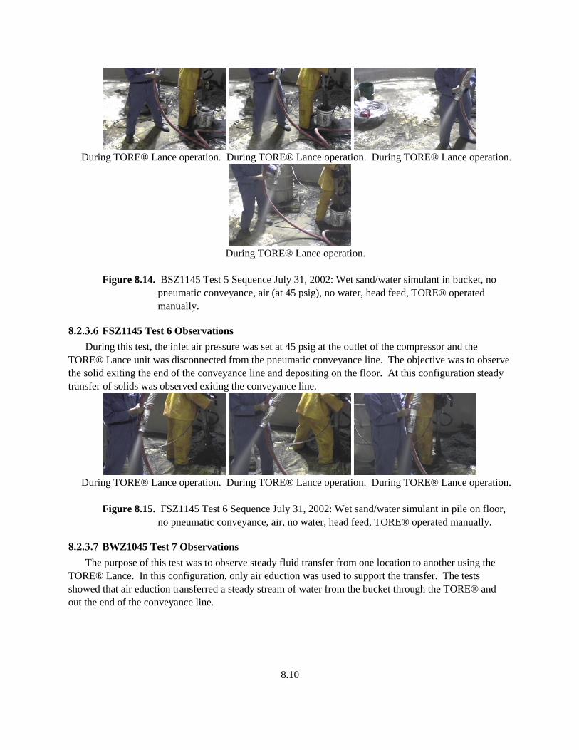
8.10
During TORE® Lance operation. During TORE® Lance operation. During TORE® Lance operation.
During TORE® Lance operation.
Figure 8.14. BSZ1145 Test 5 Sequence July 31, 2002: Wet sand/water simulant in bucket, no
pneumatic conveyance, air (at 45 psig), no water, head feed, TORE® operated
manually.
8.2.3.6 FSZ1145 Test 6 Observations
During this test, the inlet air pressure was set at 45 psig at the outlet of the compressor and the
TORE® Lance unit was disconnected from the pneumatic conveyance line. The objective was to observe
the solid exiting the end of the conveyance line and depositing on the floor. At this configuration steady
transfer of solids was observed exiting the conveyance line.
During TORE® Lance operation. During TORE® Lance operation. During TORE® Lance operation.
Figure 8.15. FSZ1145 Test 6 Sequence July 31, 2002: Wet sand/water simulant in pile on floor,
no pneumatic conveyance, air, no water, head feed, TORE® operated manually.
8.2.3.7 BWZ1045 Test 7 Observations
The purpose of this test was to observe steady fluid transfer from one location to another using the
TORE® Lance. In this configuration, only air eduction was used to support the transfer. The tests
showed that air eduction transferred a steady stream of water from the bucket through the TORE® and
out the end of the conveyance line.

8.11
During TORE® Lance operation. During TORE® Lance operation. After test conclusion
Figure 8.16. BWZ1045 Test 7 Sequence July 31, 2002: Water without solids in bucket, no
pneumatic conveyance, air, no water, no head feed, TORE® operated manually.
8.2.3.8 BWZ1145 Test 8 Observations
The purpose of this test was to repeat the prior test with the addition of mobilization air to the
TORE® Lance head. The tests showed that air mobilization and eduction also transferred a steady stream
of water from the bucket through the TORE® and out the end of the conveyance line. The flow to the
head was controlled by the position of the balance valve.
During TORE® Lance operation. After test conclusion
Figure 8.17. BWZ1145 Test 8 Sequence July 31, 2002: Water without solids in bucket, no
pneumatic conveyance, air, no water, head feed, TORE® operated manually.
8.3 Test Results
This series of tests evaluated mobilization and retrieval of solids from drums, buckets, and on the
floor. The efforts focused on fine-tuning the TORE® Lance operation. Operation at lower inlet
compressed air pressure especially in the range of 45 psig when measured at the outlet of the compressor
worked well for solids mobilization and retrieval. During unconfined tests conducted retrieving sand
from the floor permitted visualization of the presence of the precessing vortex by the pickup pattern
remaining on the floor. Solids were mobilized and retrieved. Additional fine tuning tests showed that
operation at this pressure with and without mobilization was a good combination for water transfer.
Details of the test data are listed in Table 8.2.
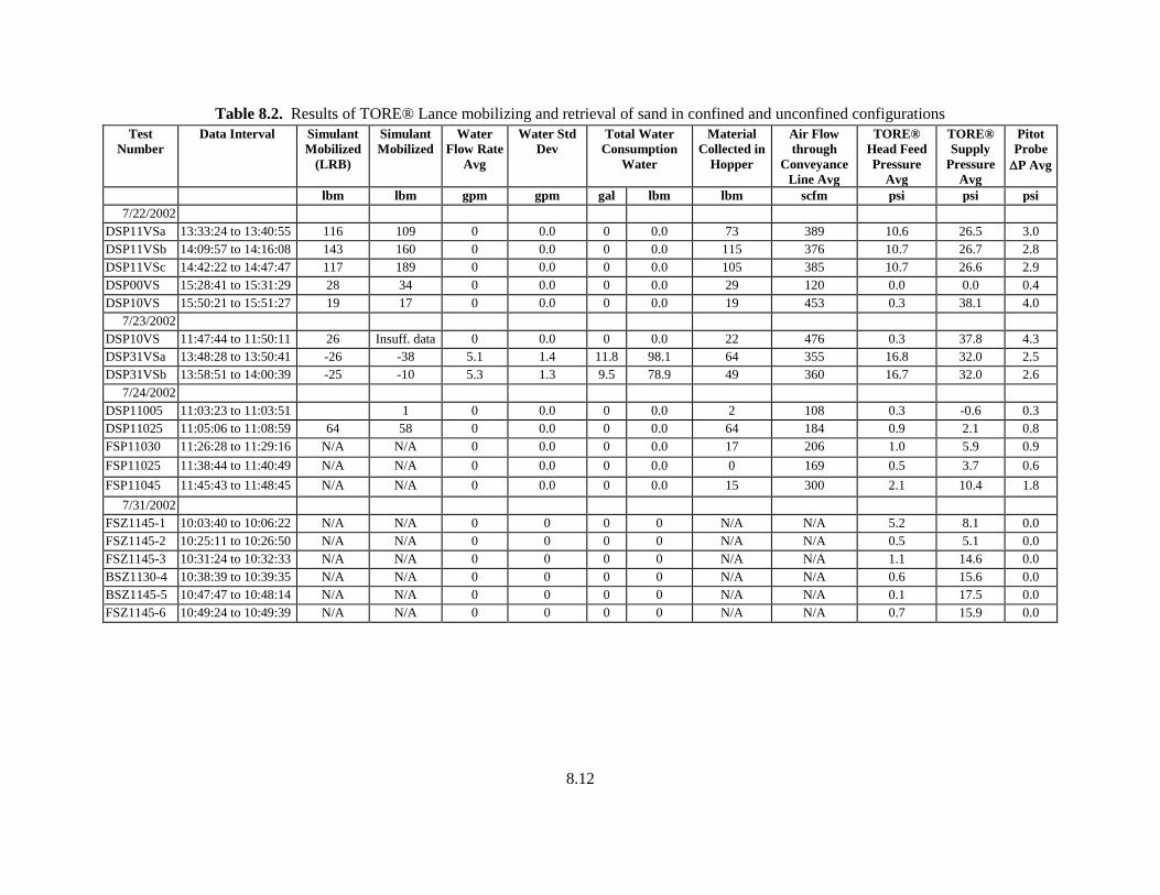
8.12
Table 8.2. Results of TORE® Lance mobilizing and retrieval of sand in confined and unconfined configurations
Test
Number
Data Interval Simulant
Mobilized
(LRB)
Simulant
Mobilized
Water
Flow Rate
Avg
Water Std
Dev
Total Water
Consumption
Water
Material
Collected in
Hopper
Air Flow
through
Conveyance
Line Avg
TORE®
Head Feed
Pressure
Avg
TORE®
Supply
Pressure
Avg
Pitot
Probe
P Avg
lbm lbm gpm gpm gal lbm lbm scfm psi psi psi
7/22/2002
DSP11VSa 13:33:24 to 13:40:55 116 109 0 0.0 0 0.0 73 389 10.6 26.5 3.0
DSP11VSb 14:09:57 to 14:16:08 143 160 0 0.0 0 0.0 115 376 10.7 26.7 2.8
DSP11VSc 14:42:22 to 14:47:47 117 189 0 0.0 0 0.0 105 385 10.7 26.6 2.9
DSP00VS 15:28:41 to 15:31:29 28 34 0 0.0 0 0.0 29 120 0.0 0.0 0.4
DSP10VS 15:50:21 to 15:51:27 19 17 0 0.0 0 0.0 19 453 0.3 38.1 4.0
7/23/2002
DSP10VS 11:47:44 to 11:50:11 26 Insuff. data 0 0.0 0 0.0 22 476 0.3 37.8 4.3
DSP31VSa 13:48:28 to 13:50:41 -26 -38 5.1 1.4 11.8 98.1 64 355 16.8 32.0 2.5
DSP31VSb 13:58:51 to 14:00:39 -25 -10 5.3 1.3 9.5 78.9 49 360 16.7 32.0 2.6
7/24/2002
DSP11005 11:03:23 to 11:03:51 1 0 0.0 0 0.0 2 108 0.3 -0.6 0.3
DSP11025 11:05:06 to 11:08:59 64 58 0 0.0 0 0.0 64 184 0.9 2.1 0.8
FSP11030 11:26:28 to 11:29:16 N/A N/A 0 0.0 0 0.0 17 206 1.0 5.9 0.9
FSP11025 11:38:44 to 11:40:49 N/A N/A 0 0.0 0 0.0 0 169 0.5 3.7 0.6
FSP11045 11:45:43 to 11:48:45 N/A N/A 0 0.0 0 0.0 15 300 2.1 10.4 1.8
7/31/2002
FSZ1145-1 10:03:40 to 10:06:22 N/A N/A 0 0 0 0 N/A N/A 5.2 8.1 0.0
FSZ1145-2 10:25:11 to 10:26:50 N/A N/A 0 0 0 0 N/A N/A 0.5 5.1 0.0
FSZ1145-3 10:31:24 to 10:32:33 N/A N/A 0 0 0 0 N/A N/A 1.1 14.6 0.0
BSZ1130-4 10:38:39 to 10:39:35 N/A N/A 0 0 0 0 N/A N/A 0.6 15.6 0.0
BSZ1145-5 10:47:47 to 10:48:14 N/A N/A 0 0 0 0 N/A N/A 0.1 17.5 0.0
FSZ1145-6 10:49:24 to 10:49:39 N/A N/A 0 0 0 0 N/A N/A 0.7 15.9 0.0
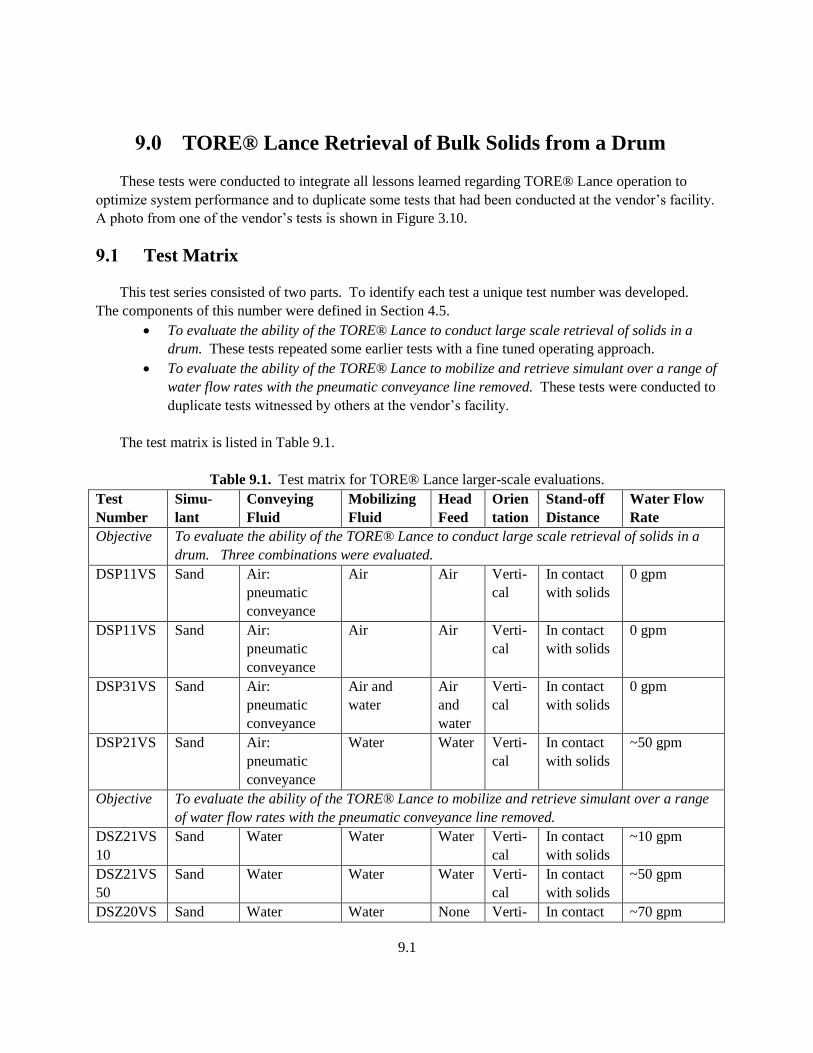
9.1
9.0 TORE® Lance Retrieval of Bulk Solids from a Drum
These tests were conducted to integrate all lessons learned regarding TORE® Lance operation to
optimize system performance and to duplicate some tests that had been conducted at the vendor’s facility.
A photo from one of the vendor’s tests is shown in Figure 3.10.
9.1 Test Matrix
This test series consisted of two parts. To identify each test a unique test number was developed.
The components of this number were defined in Section 4.5.
To evaluate the ability of the TORE® Lance to conduct large scale retrieval of solids in a
drum. These tests repeated some earlier tests with a fine tuned operating approach.
To evaluate the ability of the TORE® Lance to mobilize and retrieve simulant over a range of
water flow rates with the pneumatic conveyance line removed. These tests were conducted to
duplicate tests witnessed by others at the vendor’s facility.
The test matrix is listed in Table 9.1.
Table 9.1. Test matrix for TORE® Lance larger-scale evaluations.
Test
Number
Simu-
lant
Conveying
Fluid
Mobilizing
Fluid
Head
Feed
Orien
tation
Stand-off
Distance
Water Flow
Rate
Objective To evaluate the ability of the TORE® Lance to conduct large scale retrieval of solids in a
drum. Three combinations were evaluated.
DSP11VS Sand Air:
pneumatic
conveyance
Air Air Verti-
cal
In contact
with solids
0 gpm
DSP11VS Sand Air:
pneumatic
conveyance
Air Air Verti-
cal
In contact
with solids
0 gpm
DSP31VS Sand Air:
pneumatic
conveyance
Air and
water
Air
and
water
Verti-
cal
In contact
with solids
0 gpm
DSP21VS Sand Air:
pneumatic
conveyance
Water Water Verti-
cal
In contact
with solids
~50 gpm
Objective To evaluate the ability of the TORE® Lance to mobilize and retrieve simulant over a range
of water flow rates with the pneumatic conveyance line removed.
DSZ21VS
10
Sand Water Water Water Verti-
cal
In contact
with solids
~10 gpm
DSZ21VS
50
Sand Water Water Water Verti-
cal
In contact
with solids
~50 gpm
DSZ20VS Sand Water Water None Verti- In contact ~70 gpm
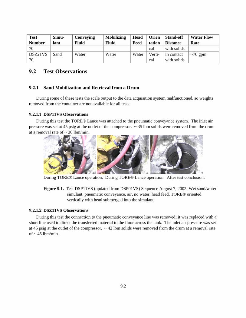
9.2
Test
Number
Simu-
lant
Conveying
Fluid
Mobilizing
Fluid
Head
Feed
Orien
tation
Stand-off
Distance
Water Flow
Rate
70 cal with solids
DSZ21VS
70
Sand Water Water Water Verti-
cal
In contact
with solids
~70 gpm
9.2 Test Observations
9.2.1 Sand Mobilization and Retrieval from a Drum
During some of these tests the scale output to the data acquisition system malfunctioned, so weights
removed from the container are not available for all tests.
9.2.1.1 DSP11VS Observations
During this test the TORE® Lance was attached to the pneumatic conveyance system. The inlet air
pressure was set at 45 psig at the outlet of the compressor. ~ 35 lbm solids were removed from the drum
at a removal rate of ~ 20 lbm/min.
During TORE® Lance operation. During TORE® Lance operation. After test conclusion.
Figure 9.1. Test DSP11VS (updated from DSP01VS) Sequence August 7, 2002: Wet sand/water
simulant, pneumatic conveyance, air, no water, head feed, TORE® oriented
vertically with head submerged into the simulant.
9.2.1.2 DSZ11VS Observations
During this test the connection to the pneumatic conveyance line was removed; it was replaced with a
short line used to direct the transferred material to the floor across the tank. The inlet air pressure was set
at 45 psig at the outlet of the compressor. ~ 42 lbm solids were removed from the drum at a removal rate
of ~ 45 lbm/min.

9.3
Before test start. During TORE® Lance operation. During TORE® Lance operation.
After test conclusion.
Figure 9.2. Test DSZ01VS Sequence August 7, 2002: Wet sand/water simulant, no pneumatic
conveyance, air, no water, head feed, TORE® oriented vertically with head
submerged into the simulant.
9.2.1.3 DSP31VS Observations
During this test the dislodging stream to the TORE® Lance head included ~ 5 gpm of water in
addition to the compressed air. The inlet air pressure was set at 45 psig at the outlet of the compressor.
Before test start. During TORE® Lance operation. During TORE® Lance operation.
During TORE® Lance operation. After test conclusion.
Figure 9.3. Test DSP31VS (updated from DSP21VS) Sequence August 7, 2002: Wet sand/water
simulant, pneumatic conveyance, air, water, head feed, TORE® oriented vertically
with head submerged into the simulant.
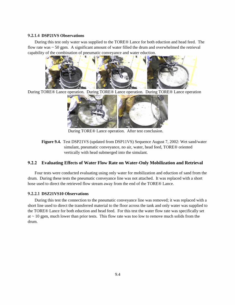
9.4
9.2.1.4 DSP21VS Observations
During this test only water was supplied to the TORE® Lance for both eduction and head feed. The
flow rate was ~ 50 gpm. A significant amount of water filled the drum and overwhelmed the retrieval
capability of the combination of pneumatic conveyance and water eduction.
During TORE® Lance operation. During TORE® Lance operation. During TORE® Lance operation
During TORE® Lance operation. After test conclusion.
Figure 9.4. Test DSP21VS (updated from DSP11VS) Sequence August 7, 2002: Wet sand/water
simulant, pneumatic conveyance, no air, water, head feed, TORE® oriented
vertically with head submerged into the simulant.
9.2.2 Evaluating Effects of Water Flow Rate on Water-Only Mobilization and Retrieval
Four tests were conducted evaluating using only water for mobilization and eduction of sand from the
drum. During these tests the pneumatic conveyance line was not attached. It was replaced with a short
hose used to direct the retrieved flow stream away from the end of the TORE® Lance.
9.2.2.1 DSZ21VS10 Observations
During this test the connection to the pneumatic conveyance line was removed; it was replaced with a
short line used to direct the transferred material to the floor across the tank and only water was supplied to
the TORE® Lance for both eduction and head feed. For this test the water flow rate was specifically set
at ~ 10 gpm, much lower than prior tests. This flow rate was too low to remove much solids from the
drum.
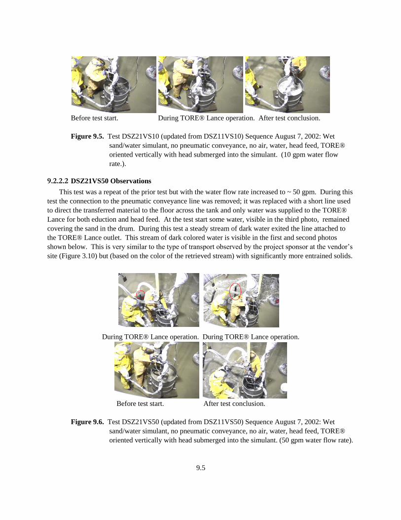
9.5
Before test start. During TORE® Lance operation. After test conclusion.
Figure 9.5. Test DSZ21VS10 (updated from DSZ11VS10) Sequence August 7, 2002: Wet
sand/water simulant, no pneumatic conveyance, no air, water, head feed, TORE®
oriented vertically with head submerged into the simulant. (10 gpm water flow
rate.).
9.2.2.2 DSZ21VS50 Observations
This test was a repeat of the prior test but with the water flow rate increased to ~ 50 gpm. During this
test the connection to the pneumatic conveyance line was removed; it was replaced with a short line used
to direct the transferred material to the floor across the tank and only water was supplied to the TORE®
Lance for both eduction and head feed. At the test start some water, visible in the third photo, remained
covering the sand in the drum. During this test a steady stream of dark water exited the line attached to
the TORE® Lance outlet. This stream of dark colored water is visible in the first and second photos
shown below. This is very similar to the type of transport observed by the project sponsor at the vendor’s
site (Figure 3.10) but (based on the color of the retrieved stream) with significantly more entrained solids.
During TORE® Lance operation. During TORE® Lance operation.
Before test start. After test conclusion.
Figure 9.6. Test DSZ21VS50 (updated from DSZ11VS50) Sequence August 7, 2002: Wet
sand/water simulant, no pneumatic conveyance, no air, water, head feed, TORE®
oriented vertically with head submerged into the simulant. (50 gpm water flow rate).
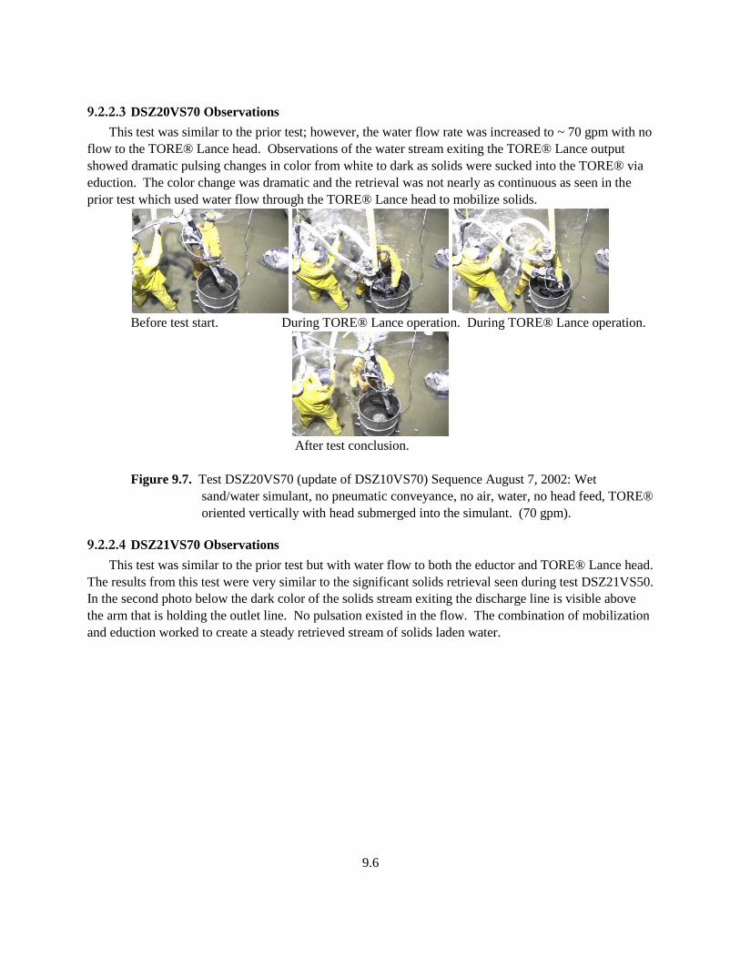
9.6
9.2.2.3 DSZ20VS70 Observations
This test was similar to the prior test; however, the water flow rate was increased to ~ 70 gpm with no
flow to the TORE® Lance head. Observations of the water stream exiting the TORE® Lance output
showed dramatic pulsing changes in color from white to dark as solids were sucked into the TORE® via
eduction. The color change was dramatic and the retrieval was not nearly as continuous as seen in the
prior test which used water flow through the TORE® Lance head to mobilize solids.
Before test start. During TORE® Lance operation. During TORE® Lance operation.
After test conclusion.
Figure 9.7. Test DSZ20VS70 (update of DSZ10VS70) Sequence August 7, 2002: Wet
sand/water simulant, no pneumatic conveyance, no air, water, no head feed, TORE®
oriented vertically with head submerged into the simulant. (70 gpm).
9.2.2.4 DSZ21VS70 Observations
This test was similar to the prior test but with water flow to both the eductor and TORE® Lance head.
The results from this test were very similar to the significant solids retrieval seen during test DSZ21VS50.
In the second photo below the dark color of the solids stream exiting the discharge line is visible above
the arm that is holding the outlet line. No pulsation existed in the flow. The combination of mobilization
and eduction worked to create a steady retrieved stream of solids laden water.
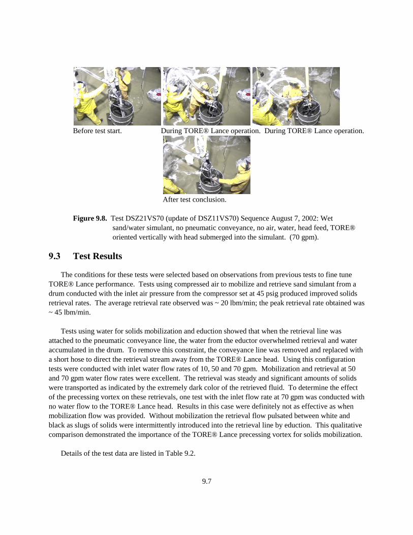
9.7
Before test start. During TORE® Lance operation. During TORE® Lance operation.
After test conclusion.
Figure 9.8. Test DSZ21VS70 (update of DSZ11VS70) Sequence August 7, 2002: Wet
sand/water simulant, no pneumatic conveyance, no air, water, head feed, TORE®
oriented vertically with head submerged into the simulant. (70 gpm).
9.3 Test Results
The conditions for these tests were selected based on observations from previous tests to fine tune
TORE® Lance performance. Tests using compressed air to mobilize and retrieve sand simulant from a
drum conducted with the inlet air pressure from the compressor set at 45 psig produced improved solids
retrieval rates. The average retrieval rate observed was ~ 20 lbm/min; the peak retrieval rate obtained was
~ 45 lbm/min.
Tests using water for solids mobilization and eduction showed that when the retrieval line was
attached to the pneumatic conveyance line, the water from the eductor overwhelmed retrieval and water
accumulated in the drum. To remove this constraint, the conveyance line was removed and replaced with
a short hose to direct the retrieval stream away from the TORE® Lance head. Using this configuration
tests were conducted with inlet water flow rates of 10, 50 and 70 gpm. Mobilization and retrieval at 50
and 70 gpm water flow rates were excellent. The retrieval was steady and significant amounts of solids
were transported as indicated by the extremely dark color of the retrieved fluid. To determine the effect
of the precessing vortex on these retrievals, one test with the inlet flow rate at 70 gpm was conducted with
no water flow to the TORE® Lance head. Results in this case were definitely not as effective as when
mobilization flow was provided. Without mobilization the retrieval flow pulsated between white and
black as slugs of solids were intermittently introduced into the retrieval line by eduction. This qualitative
comparison demonstrated the importance of the TORE® Lance precessing vortex for solids mobilization.
Details of the test data are listed in Table 9.2.
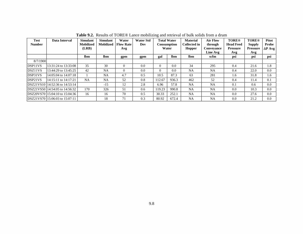
9.8
Table 9.2. Results of TORE® Lance mobilizing and retrieval of bulk solids from a drum
Test
Number
Data Interval Simulant
Mobilized
(LRB)
Simulant
Mobilized
Water
Flow Rate
Avg
Water Std
Dev
Total Water
Consumption
Water
Material
Collected in
Hopper
Air Flow
through
Conveyance
Line Avg
TORE®
Head Feed
Pressure
Avg
TORE®
Supply
Pressure
Avg
Pitot
Probe
P Avg
lbm lbm gpm gpm gal lbm lbm scfm psi psi psi
8/7/1900
DSP11VS 13:31:24 to 13:33:08 35 30 0 0.0 0 0.0 34 295 0.4 21.6 1.8
DSZ11VS 13:44:29 to 13:45:25 42 NA 0 0.0 0 0.0 NA NA 0.4 22.0 0.0
DSP31VS 14:05:04 to 14:07:18 1 NA 4.7 0.5 10.5 87.3 63 281 1.6 31.8 1.6
DSP21VS 14:15:11 to 14:17:21 NA NA 52 0.8 112.67 936.3 462 52 0.4 11.4 0.1
DSZ21VS10 14:52:36 to 14:53:14 -15 12 2.8 6.96 57.8 NA NA 0.1 0.6 0.0
DSZ21VS50 14:54:05 to 14:56:32 170 326 51 0.6 119.23 990.8 NA NA 0.0 10.3 0.0
DSZ20VS70 15:04:10 to 15:04:36 16 16 70 0.5 30.33 252.1 NA NA 0.0 27.6 0.0
DSZ21VS70 15:06:03 to 15:07:11 18 71 0.3 80.92 672.4 NA NA 0.0 21.2 0.0
10.1
10.0 References
Bamberger, J. A., B. K. Hatchell, B. E. Lewis, and J. D. Randolph. 2001. Evaluation of Technologies for
Retrieval of Waste from Leaking Tanks. PNNL-13770. Pacific Northwest National Laboratory,
Richland, Washington.
Bamberger, JA, MA McKinnon, DA Alberts, DE Steele, and CT Crowe. 1994. FY93 Summary Report
Development of a Multi-Functional Scarifier Dislodger with an Integral Pneumatic Conveyance
Retrieval System for Single-Shell Tank Remediation. PNL-8901, Pacific Northwest Laboratory,
Richland, Washington.
Chard, S.J., K. Nezhati, J.E. Delves, A.C. Lockier, D.J. Parkinson. 1996. “Evaluation of the TORE® for
Hydrotransport and its Application”. 13th International Conference on Slurry Handling and Pipeline
Transport: HYDROTRANSPORT 13, Johannesburg, South Africa. September 3-5, 1996.
Estey, S. D. 2001. Engineering Calculation: Project W-523, Single-Shell Tank 241-C-104 Mobile
Retrieval System Waste Transport Property and Critical Velocity Analysis. RPP-8915, Rev. 0.
CH2M Hill Hanford Group, Inc., Richland, Washington.
Estey, S. D. 2001. Engineering Calculation: Project W-523, Single-Shell Tank 241-C-104 Mobile
Retrieval System Waste Transport Property and Critical Velocity Analysis. RPP-8915, Rev. 0.
CH2M Hill Hanford Group, Inc., Richland, Washington.
Estey, S. D. 2001. Engineering Calculation: Project W-523, Single-Shell Tank 241-C-104 Mobile
Retrieval System Waste Transport Property and Critical Velocity Analysis. RPP-8915, Rev. 0A.
CH2M Hill Hanford Group, Inc., Richland, Washington.
Estey, S. D. 2001. Engineering Calculation: Project W-523, Single-Shell Tank 241-C-104 Mobile
Retrieval System Waste Transport Property and Critical Velocity Analysis. RPP-8915, Rev. 0B.
CH2M Hill Hanford Group, Inc., Richland, Washington.
Faram, M.G., N. Syred, T. O’Doherty. 1996. “Studies of Novel Devices for Slurry Transportation”.
13th International Conference on Slurry Handling and Pipeline Transport: HYDROTRANSPORT 13,
Johannesburg, South Africa. September 3-5, 1996.
Golcar, G. R., M. R. Powell, J. R. Bontha, P. A. Smith, J. G. Darab, and J. Zhang. 1997. Retrieval
Process Development and Enhancements Project Fiscal Year 1995 Simulant Development
Technology Task Progress Report. PNNL-11103, Pacific Northwest National Laboratory, Richland,
Washington.
10.2
Holm, M. J. 2001. Specification for 241-C-104 Mobile Retrieval System. RPP-7420, Rev. 0. CH2M
Hill Hanford Group, Inc., Richland, Washington.
Jewett, J. R., S. D. Estey, L. Jensen, N. W. Kirch, D. A. Reynolds, Y. Onishi. 2002. Values of Particle
Size, Particle Density, and Slurry Viscosity to Use in Waste Feed Delivery Transfer System
Analysis.RPP-9805, Rev. 1a, Numatec Hanford Corporation, Richland, Washington.
O’Rourke, J. F. 2000. Results of Retrieval Studies with Waste from Tank 241-C-104. RPP_5798, Rev.
0A.
O’Rourke, J. F. 2000. Results of Retrieval Studies with Waste from Tank 241-C-104. RPP_5798, Rev.
0A.
O’Rourke, J. F. 2001. Results of Retrieval Studies with Waste from Tank 241-C-104. RPP_5798, Rev.
0B.
Parkinson, D., J Delves. 1999. “Continuous TORE® Hydrotransport system”. 14th International
Conference on Slurry Handling and Pipeline Transport: HYDROTRANSPORT 14, Maastricht,
The Netherlands. September 8-10 1999.
Powell, M. R., G. R. Golcar, and J. G. H. Geeting. 1997. Retrieval Process Development and
Enhancements Waste Simulant Compositions and Defensibility. PNNL-11685, Pacific Northwest
National Laboratory, Richland, Washington.
11.1
11.0 Distribution
No. of
Copies
OFFSITE
1 DOE/Office of Scientific and Technical
Information and Information Release
ONSITE
1 Tanks Focus Area Program Lead
T. P. Pietrok K8-50
1 Retrieval Technology Integration
Manager
P. W. Gibbons K9-91
1 Tanks Focus Area Technical Team
B. J. Williams K9-69
9 Hanford Site
J. R. Biggs R4-08
J. W. Cammann R2-39
K. E. Carpenter S7-90
P. J. Certa R3-73
A. F. Choho R3-73
K. A. Gasper L4-07
M. G. Glasper K8-50
D. B. Smet S7-90
W. T. Thompson R3-73
No. of
Copies
ONSITE
12 Pacific Northwest National Laboratory
J. A. Bamberger (2) K7-15
C. J. Bates K7-15
J. M. Bates K7-15
J. W. Brothers (2) K7-15
B. K. Hatchell K5-22
J. L. Huckaby K7-15
W. L. Kuhn K7-15
P. A. Meyer K7-15
M. W. Rinker K5-22
M. White K7-15