Embed Size (px)
Citation preview

EVALUATION OF TRANSIT SIGNAL PRIORITY EFFECTIVENESS
USING AUTOMATIC VEHICLE LOCATION DATA
A Thesis Presented to
The Academic Faculty
by
Carl Andrew Sundstrom
In Partial Fulfillment of the Requirements for the Degree
Masters of Science in the School of Civil Engineering
Georgia Institute of Technology May 2008

EVALUATION OF TRANSIT SIGNAL PRIORITY EFFECTIVENESS
USING AUTOMATIC VEHICLE LOCATION DATA
Approved by:
Dr. Michael Meyer, Advisor School of Civil Engineering Georgia Institute of Technology Dr. Laurie Garrow School of Civil Engineering Georgia Institute of Technology Dr. Michael Hunter School of Civil Engineering Georgia Institute of Technology Date Approved: March 30, 2008

iii
ACKNOWLEDGMENTS
I owe gratitude to a great number of people who, without their gracious help, this
thesis would not have been written. First, I would like to express my sincere appreciate to
Dr. Michael D. Meyer for all of his help and guidance throughout my time at Georgia Tech.
I would also like to express my thanks to the rest of my thesis committee, Dr. Laurie Garrow
and Dr. Michael Hunter, for their help in the analysis and review of this project.
Sincere thanks are also necessary to everyone in Portland who took the time to help
me this research. In particular, thanks to Mr. Peter Koonce for his help and direction in
narrowing this topic and setting up the data collection efforts. The staff at Kittelson and
Associates, not limited to but including, Wayne Kittelson, Lee Rodegerdts, and Paul Ryus for
their tremendous help and resources. I am also deeply grateful for the staff at the Portland
Office of Transportation and TriMet, including Bill Kloos, David Crout, and Paul Zebell, for
their help in this project.
Finally, I would like to express thanks to my parents, Mr. Robert Sundstrom and Mrs.
Chary Sundstrom, for their love and support throughout the years and Ms. Kristen Pleil for
the support, inspiration, and friendship that she has provided.

iv
TABLE OF CONTENTS
Page
ACKNOWLEDGMENTS .................................................................................................................................... III
LIST OF TABLES ................................................................................................................................................ VI
LIST OF FIGURES .............................................................................................................................................VII
SUMMARY ........................................................................................................................................................... XI
CHAPTER 1 INTRODUCTION ............................................................................................................................1
1.1 STUDY OVERVIEW ........................................................................................................................................2 1.2 LITERATURE REVIEW....................................................................................................................................3 1.3 FIELD DATA COLLECTION AND PROCESSING................................................................................................3 1.4 ANALYSIS AND FINDINGS .............................................................................................................................3 1.5 CONCLUSIONS...............................................................................................................................................4 1.6 APPENDICES.................................................................................................................................................4
CHAPTER 2 LITERATURE REVIEW ................................................................................................................5
2.1 PORTLAND, OREGON TSP EVALUATIONS .....................................................................................................5 2.1.1 Portland Signal Priority: TEA-21 Technical Report (2003)...............................................................5 2.1.2 Byrne et al. (2005) ..............................................................................................................................7 2.1.3 Kimpel et al. (2005) ............................................................................................................................9
2.2 OTHER TSP RESEARCH...............................................................................................................................10 2.2.1 Liao and Davis (2007) ......................................................................................................................10 2.2.2 Ngan, Sayed, and Abdelfatah (2004) ................................................................................................11 2.2.3 Muthuswamy, McShane, and Daniel (2006).....................................................................................14 2.2.4 Sacramento: Watt Avenue Transit Priority Evaluation (2006).........................................................14 2.2.5 Virginia Tech Transit Signal Priority Evaluation (2006) .................................................................15 2.2.6 98 B-Line Bus Rapid Transit Evaluation Study (2003).....................................................................16 2.2.7 Garrow and Machemehl (1997)........................................................................................................17
2.3 LITERATURE REVIEW SUMMARY ................................................................................................................18
CHAPTER 3 FIELD DATA COLLECTION AND PROCESSING ..... ............................................................19
3.1 STUDY CORRIDOR.......................................................................................................................................19 3.1.1 Corridor Conditions .........................................................................................................................21
3.2 FIELD DATA COLLECTION ..........................................................................................................................22 3.2.1 Automatic Vehicle Location System..................................................................................................22 3.2.2 Conditional Priority System..............................................................................................................23
3.3 FIELD DATA PROCESSING AND QUALITY CONTROL....................................................................................26 3.3.1 Data Processing................................................................................................................................26 3.3.2 Quality Control .................................................................................................................................27
CHAPTER 4 ANALYSIS AND FINDINGS........................................................................................................29
4.1 TRAVEL TIME .............................................................................................................................................29 4.1.1 Northbound Travel Times .................................................................................................................29 4.1.2 Southbound Travel Times .................................................................................................................33
4.2 SCHEDULE ADHERENCE..............................................................................................................................37 4.2.1 Northbound Schedule Adherence......................................................................................................38 4.2.2 Southbound Schedule Adherence......................................................................................................44
4.3 SUMMARY OF ANALYSIS AND FINDINGS.....................................................................................................50

v
CHAPTER 5 CONCLUSIONS.............................................................................................................................51
5.1 BUS STOP PLACEMENT ...............................................................................................................................51 5.2 TRAFFIC SIGNAL TIMING AND CROSS-STREET TRAFFIC CONSIDERATIONS.................................................56 5.3 LIMITATIONS OF THIS RESEARCH...............................................................................................................57 5.4 FUTURE RESEARCH RECOMMENDATIONS...................................................................................................58
APPENDIX A .........................................................................................................................................................59
APPENDIX B .........................................................................................................................................................83
REFERENCES.....................................................................................................................................................107
vi
LIST OF TABLES
TABLE 2.1 BUS TRAVEL TIME SUMMARY (ALL TRIPS) ..........................................................................................6 TABLE 2.2 BUS TRAVEL TIME SUMMARY (LATE TRIPS ONLY) ..............................................................................6 TABLE 2.3 TRAVEL TIMES PER BUS SIMULATION RESULTS ....................................................................................8 TABLE 2.4 SIMULATION RESULTS FOR DELAY PER BUS .........................................................................................9 TABLE 2.5 TRAVEL TIMES FOR TSP AND NON-TSP BUSES, ALL SEGMENTS ........................................................15 TABLE 2.6 DETAILED TRAVEL TIME RESULTS [ ....................................................................................................16 TABLE 2.7 TRAVEL TIME STATISTICS, A IRPORT STATION – WEST HASTINGS STREET .........................................16 TABLE 2.8 SCHEDULE ADHERENCE STATISTICS DOWNTOWN VANCOUVER SECTION ...........................................17 TABLE 2.9 NEGATIVE IMPACTS ACCRUING ON CROSS-STREETS DUE TO SIGNAL PRIORITY (ASSUMED BUS
HEADWAY = 10 MINUTES) ..........................................................................................................................18 TABLE 3.1 TRAVEL TIME OUTLIER DETERMINATION ............................................................................................28 TABLE 3.2 STATISTICAL COMPARISON OF TRAVEL TIME DATA SET WITH AND WITHOUT OUTLIERS...................28 TABLE 3.3 STATISTICAL COMPARISON OF SCHEDULE ADHERENCE DATA SET WITH AND WITHOUT OUTLIERS........28 TABLE 4.1TRAVEL TIME COMPARISON: NORTHBOUND ........................................................................................30 TABLE 4.2 TRAVEL TIME COMPARISON: SOUTHBOUND........................................................................................34 TABLE 4.3 INCREASE IN LATE ARRIVAL COMPARISON: NORTHBOUND.................................................................39 TABLE 4.5 INCREASE IN LATE ARRIVAL COMPARISON: SOUTHBOUND .................................................................44 TABLE 5.1 BUS STOP POSITIONS – NORTHBOUND.................................................................................................52 TABLE 5.2 BUS STOP POSITIONS – SOUTHBOUND .................................................................................................53 TABLE 5.3 TRAFFIC SIGNAL TIMING CONSIDERATIONS FOR SIGNAL PRIORITY ....................................................57

vii
LIST OF FIGURES
FIGURE 2.1 RUN TIME DISTRIBUTION – PM PEAK TRIPS ........................................................................................7 FIGURE 2.2 AM AND PM PEAK BUS SPEED AND TRAVEL TIME ............................................................................11 FIGURE 2.3 IMPACT ON BUS TRAVEL TIME ...........................................................................................................12 FIGURE 2.4 BUS STOP LOCATION IMPACT ON AVERAGE BUS DELAY (WITH TSP) ...............................................13 FIGURE 2.5 NEARSIDE BUS STOP IMPACT ON TSP EFFECTIVENESS ......................................................................13 FIGURE 3.1 STUDY CORRIDOR MAP ......................................................................................................................20 FIGURE 3.2 NE 82ND
AVENUE IN PORTLAND, OREGON..........................................................................................21 FIGURE 3.3 DECISION FRAMEWORK FOR EMITTER ACTIVATION ..........................................................................24 FIGURE 3.4 DECISION FRAMEWORK FOR TSP STRATEGY TO EMPLOY ..................................................................25 FIGURE 3.5 GENERAL SIGNAL PRIORTY CONCEPT ................................................................................................26 FIGURE 4.1 COMPARISON OF AVERAGE VEHICLE TRAVEL TIMES NORTHBOUND: TOTAL STUDY PERIOD............31 FIGURE 4.2 COMPARISON OF AVERAGE VEHICLE TRAVEL TIMES NORTHBOUND: WEEKDAY, AM PEAK PERIOD 31 FIGURE 4.3 COMPARISON OF AVERAGE VEHICLE TRAVEL TIMES NORTHBOUND: WEEKDAY, PM PEAK PERIOD.32 FIGURE 4.4 COMPARISON OF AVERAGE VEHICLE TRAVEL TIMES NORTHBOUND: WEEKDAY, NON-PEAK PERIOD
....................................................................................................................................................................32 FIGURE 4.5 COMPARISON OF AVERAGE VEHICLE TRAVEL TIMES NORTHBOUND: WEEKEND...............................33 FIGURE 4.6 COMPARISON OF AVERAGE VEHICLE TRAVEL TIMES SOUTHBOUND: TOTAL STUDY PERIOD.............35 FIGURE 4.7 COMPARISON OF AVERAGE VEHICLE TRAVEL TIMES SOUTHBOUND: WEEKDAY, AM PEAK PERIOD.35 FIGURE 4.8 COMPARISON OF AVERAGE VEHICLE TRAVEL TIMES SOUTHBOUND: WEEKDAY, PM PEAK PERIOD..36 FIGURE 4.9 COMPARISON OF AVERAGE VEHICLE TRAVEL TIMES SOUTHBOUND: WEEKDAY, NON-PEAK PERIOD36 FIGURE 4.10 COMPARISON OF AVERAGE VEHICLE TRAVEL TIMES SOUTHBOUND: WEEKEND..............................37 FIGURE 4.11 COMPARISON OF INCREASE IN LATE ARRIVAL TO SCHEDULE THROUGH CORRIDOR NORTHBOUND:
TOTAL STUDY PERIOD.................................................................................................................................41 FIGURE 4.12COMPARISON OF INCREASE IN LATE ARRIVAL TO SCHEDULE THROUGH CORRIDOR NORTHBOUND:
WEEKDAY, AM PEAK PERIOD.....................................................................................................................42 FIGURE 4.13 COMPARISON OF INCREASE IN LATE ARRIVAL TO SCHEDULE THROUGH CORRIDOR NORTHBOUND:
WEEKDAY, PM PEAK PERIOD......................................................................................................................42 FIGURE 4.14 COMPARISON OF INCREASE IN LATE ARRIVAL TO SCHEDULE THROUGH CORRIDOR NORTHBOUND:
WEEKDAY, NON-PEAK PERIOD....................................................................................................................43 FIGURE 4.15 COMPARISON OF INCREASE IN LATE ARRIVAL TO SCHEDULE THROUGH CORRIDOR NORTHBOUND:
WEEKEND....................................................................................................................................................43 FIGURE 4.16 COMPARISON OF INCREASE IN LATE ARRIVAL TO SCHEDULE THROUGH CORRIDOR SOUTHBOUND:
TOTAL STUDY PERIOD.................................................................................................................................47 FIGURE 4.17 COMPARISON OF INCREASE IN LATE ARRIVAL TO SCHEDULE THROUGH CORRIDOR SOUTHBOUND:
WEEKDAY, AM PEAK PERIOD.....................................................................................................................48 FIGURE 4.18 COMPARISON OF INCREASE IN LATE ARRIVAL TO SCHEDULE THROUGH CORRIDOR SOUTHBOUND:
WEEKDAY, PM PEAK PERIOD......................................................................................................................48 FIGURE 4.19 COMPARISON OF INCREASE IN LATE ARRIVAL TO SCHEDULE THROUGH CORRIDOR SOUTHBOUND:
WEEKDAY, NON-PEAK PERIOD....................................................................................................................49 FIGURE 4.20 COMPARISON OF INCREASE IN LATE ARRIVAL TO SCHEDULE THROUGH CORRIDOR SOUTHBOUND:
WEEKEND....................................................................................................................................................49 FIGURE 5.1 PERCENTAGE OF BUS STOPS THAT ARE LOCATED NEARSIDE OF A SIGNALIZED INTERSECTION..........53 FIGURE 5.2 BUS STOP PERCENTAGE - NORTHBOUND............................................................................................54 FIGURE 5.3 BUS STOP PERCENTAGE - SOUTHBOUND.............................................................................................55 FIGURE A.1 NORTHBOUND VEHICLE TRAVEL TIMES, AM PEAK PERIOD, TSP OFF.............................................59 FIGURE A.2 NORTHBOUND VEHICLE TRAVEL TIMES, WEEKDAY AM PEAK PERIOD, TSP OFF ...........................59 FIGURE A.3 NORTHBOUND VEHICLE TRAVEL TIMES, WEEKEND AM PEAK PERIOD, TSP OFF............................60 FIGURE A.4 NORTHBOUND VEHICLE TRAVEL TIMES, NON-PEAK PERIOD, TSP OFF ...........................................60 FIGURE A.5 NORTHBOUND VEHICLE TRAVEL TIMES, WEEKDAY NON-PEAK PERIOD, TSP OFF..........................61 FIGURE A.6 NORTHBOUND VEHICLE TRAVEL TIMES, WEEKEND NON-PEAK PERIOD, TSP OFF ..........................61

viii
FIGURE A.7 NORTHBOUND VEHICLE TRAVEL TIMES, PM PEAK PERIOD, TSP OFF..............................................62 FIGURE A.8 NORTHBOUND VEHICLE TRAVEL TIMES, WEEKDAY PM PEAK PERIOD, TSP OFF ............................62 FIGURE A.9 NORTHBOUND VEHICLE TRAVEL TIMES, WEEKEND PM PEAK PERIOD, TSP OFF.............................63 FIGURE A.10 NORTHBOUND VEHICLE TRAVEL TIMES, TOTAL STUDY PERIOD, TSP OFF ....................................63 FIGURE A.11 NORTHBOUND VEHICLE TRAVEL TIMES, WEEKDAY TOTAL STUDY PERIOD, TSP OFF...................64 FIGURE A.12 NORTHBOUND VEHICLE TRAVEL TIMES, WEEKEND TOTAL STUDY PERIOD, TSP OFF...................64 FIGURE A.13 SOUTHBOUND VEHICLE TRAVEL TIMES, AM PEAK PERIOD, TSP OFF............................................65 FIGURE A.14 SOUTHBOUND VEHICLE TRAVEL TIMES, WEEKDAY AM PEAK PERIOD, TSP OFF..........................65 FIGURE A.15 SOUTHBOUND VEHICLE TRAVEL TIMES, WEEKEND AM PEAK PERIOD, TSP OFF ..........................66 FIGURE A.16 SOUTHBOUND VEHICLE TRAVEL TIMES, NON-PEAK PERIOD, TSP OFF..........................................66 FIGURE A.17 SOUTHBOUND VEHICLE TRAVEL TIMES, WEEKDAY NON-PEAK PERIOD, TSP OFF ........................67 FIGURE A.18 SOUTHBOUND VEHICLE TRAVEL TIMES, WEEKEND NON-PEAK PERIOD, TSP OFF.........................67 FIGURE A.19 SOUTHBOUND VEHICLE TRAVEL TIMES, PM PEAK PERIOD, TSP OFF ............................................68 FIGURE A.20 SOUTHBOUND VEHICLE TRAVEL TIMES, WEEKDAY PM PEAK PERIOD, TSP OFF...........................68 FIGURE A.21 SOUTHBOUND VEHICLE TRAVEL TIMES, WEEKEND PM PEAK PERIOD, TSP OFF...........................69 FIGURE A.22 SOUTHBOUND VEHICLE TRAVEL TIMES, TOTAL STUDY PERIOD, TSP OFF.....................................69 FIGURE A.23 SOUTHBOUND VEHICLE TRAVEL TIMES, WEEKDAY TOTAL STUDY PERIOD, TSP OFF ...................70 FIGURE A.24 SOUTHBOUND VEHICLE TRAVEL TIMES, WEEKEND TOTAL STUDY PERIOD, TSP OFF....................70 FIGURE A.25 NORTHBOUND VEHICLE TRAVEL TIMES, AM PEAK PERIOD, TSP ON.............................................71 FIGURE A.26 NORTHBOUND VEHICLE TRAVEL TIMES, WEEKDAY AM PEAK PERIOD, TSP ON...........................71 FIGURE A.27 NORTHBOUND VEHICLE TRAVEL TIMES, WEEKEND AM PEAK PERIOD, TSP ON ...........................72 FIGURE A.28 NORTHBOUND VEHICLE TRAVEL TIMES, NON-PEAK PERIOD, TSP ON...........................................72 FIGURE A.29 NORTHBOUND VEHICLE TRAVEL TIMES, WEEKDAY NON-PEAK PERIOD, TSP ON .........................73 FIGURE A.30 NORTHBOUND VEHICLE TRAVEL TIMES, WEEKEND NON-PEAK PERIOD, TSP ON..........................73 FIGURE A.31 NORTHBOUND VEHICLE TRAVEL TIMES, PM PEAK PERIOD, TSP ON .............................................74 FIGURE A.32 NORTHBOUND VEHICLE TRAVEL TIMES, WEEKDAY PM PEAK PERIOD, TSP ON............................74 FIGURE A.33 NORTHBOUND VEHICLE TRAVEL TIMES, WEEKEND PM PEAK PERIOD, TSP ON............................75 FIGURE A.34 NORTHBOUND VEHICLE TRAVEL TIMES, TOTAL STUDY PERIOD, TSP ON......................................75 FIGURE A.35 NORTHBOUND VEHICLE TRAVEL TIMES, WEEKDAY TOTAL STUDY PERIOD, TSP ON ....................76 FIGURE A.36 SOUTHBOUND VEHICLE TRAVEL TIMES, AM PEAK PERIOD, TSP ON.............................................76 FIGURE A.37 SOUTHBOUND VEHICLE TRAVEL TIMES, WEEKDAY AM PEAK PERIOD, TSP ON............................77 FIGURE A.38 SOUTHBOUND VEHICLE TRAVEL TIMES, WEEKEND AM PEAK PERIOD, TSP ON............................77 FIGURE A.39 SOUTHBOUND VEHICLE TRAVEL TIMES, NON-PEAK PERIOD, TSP ON ...........................................78 FIGURE A.40 SOUTHBOUND VEHICLE TRAVEL TIMES, WEEKDAY NON-PEAK PERIOD, TSP ON..........................78 FIGURE A.41 SOUTHBOUND VEHICLE TRAVEL TIMES, WEEKEND NON-PEAK PERIOD, TSP ON ..........................79 FIGURE A.42 SOUTHBOUND VEHICLE TRAVEL TIMES, PM PEAK PERIOD, TSP ON..............................................79 FIGURE A.43 SOUTHBOUND VEHICLE TRAVEL TIMES, WEEKDAY PM PEAK PERIOD, TSP ON ............................80 FIGURE A.44 SOUTHBOUND VEHICLE TRAVEL TIMES, WEEKEND PM PEAK PERIOD, TSP ON.............................80 FIGURE A.45 SOUTHBOUND VEHICLE TRAVEL TIMES, TOTAL STUDY PERIOD, TSP ON ......................................81 FIGURE A.46 SOUTHBOUND VEHICLE TRAVEL TIMES, WEEKDAY TOTAL STUDY PERIOD, TSP ON.....................81 FIGURE A.47 SOUTHBOUND VEHICLE TRAVEL TIMES, WEEKEND TOTAL STUDY PERIOD, TSP ON.....................82 FIGURE B.1 INCREASE IN LATE ARRIVAL TO SCHEDULE THROUGH CORRIDOR NORTHBOUND: AM PEAK PERIOD,
TSP OFF .....................................................................................................................................................83 FIGURE B.2 INCREASE IN LATE ARRIVAL TO SCHEDULE THROUGH CORRIDOR NORTHBOUND: NON-PEAK PERIOD,
TSP OFF .....................................................................................................................................................83 FIGURE B.3 INCREASE IN LATE ARRIVAL TO SCHEDULE THROUGH CORRIDOR NORTHBOUND: PM PEAK PERIOD,
TSP OFF .....................................................................................................................................................84 FIGURE B.4 INCREASE IN LATE ARRIVAL TO SCHEDULE THROUGH CORRIDOR NORTHBOUND: WEEKDAY, TSP
OFF.............................................................................................................................................................84 FIGURE B.5 INCREASE IN LATE ARRIVAL TO SCHEDULE THROUGH CORRIDOR NORTHBOUND: WEEKDAY, AM
PEAK PERIOD, TSP OFF ..............................................................................................................................85 FIGURE B.6 INCREASE IN LATE ARRIVAL TO SCHEDULE THROUGH CORRIDOR NORTHBOUND: WEEKDAY, NON-
PEAK PERIOD, TSP OFF ..............................................................................................................................85 FIGURE B.7 INCREASE IN LATE ARRIVAL TO SCHEDULE THROUGH CORRIDOR NORTHBOUND: WEEKDAY, PM
PEAK PERIOD, TSP OFF ..............................................................................................................................86

ix
FIGURE B.8 INCREASE IN LATE ARRIVAL TO SCHEDULE THROUGH CORRIDOR NORTHBOUND: WEEKEND, TSP
OFF.............................................................................................................................................................86 FIGURE B.9 INCREASE IN LATE ARRIVAL TO SCHEDULE THROUGH CORRIDOR NORTHBOUND: WEEKEND, AM
PEAK PERIOD, TSP OFF ..............................................................................................................................87 FIGURE B.10 INCREASE IN LATE ARRIVAL TO SCHEDULE THROUGH CORRIDOR NORTHBOUND: WEEKEND, NON-
PEAK PERIOD, TSP OFF ..............................................................................................................................87 FIGURE B.11 INCREASE IN LATE ARRIVAL TO SCHEDULE THROUGH CORRIDOR NORTHBOUND: WEEKEND, PM
PEAK PERIOD, TSP OFF ..............................................................................................................................88 FIGURE B.12 INCREASE IN LATE ARRIVAL TO SCHEDULE THROUGH CORRIDOR NORTHBOUND: TOTAL STUDY
PERIOD, TSP OFF........................................................................................................................................88 FIGURE B.13 INCREASE IN LATE ARRIVAL TO SCHEDULE THROUGH CORRIDOR NORTHBOUND: TOTAL STUDY
PERIOD, AM PEAK PERIOD, TSP OFF .........................................................................................................89 FIGURE B.14 INCREASE IN LATE ARRIVAL TO SCHEDULE THROUGH CORRIDOR NORTHBOUND: TOTAL STUDY
PERIOD, NON-PERIOD, TSP OFF .................................................................................................................89 FIGURE B.15 INCREASE IN LATE ARRIVAL TO SCHEDULE THROUGH CORRIDOR NORTHBOUND: TOTAL STUDY
PERIOD, PM PEAK PERIOD, TSP OFF..........................................................................................................90 FIGURE B.16 INCREASE IN LATE ARRIVAL TO SCHEDULE THROUGH CORRIDOR SOUTHBOUND: WEEKDAY, TSP
OFF.............................................................................................................................................................90 FIGURE B.17 INCREASE IN LATE ARRIVAL TO SCHEDULE THROUGH CORRIDOR SOUTHBOUND: WEEKDAY, AM
PEAK PERIOD, TSP OFF ..............................................................................................................................91 FIGURE B.18 INCREASE IN LATE ARRIVAL TO SCHEDULE THROUGH CORRIDOR SOUTHBOUND: WEEKDAY, NON-
PEAK PERIOD, TSP OFF ..............................................................................................................................91 FIGURE B.19 INCREASE IN LATE ARRIVAL TO SCHEDULE THROUGH CORRIDOR SOUTHBOUND: WEEKDAY, PM
PEAK PERIOD, TSP OFF ..............................................................................................................................92 FIGURE B.20 INCREASE IN LATE ARRIVAL TO SCHEDULE THROUGH CORRIDOR SOUTHBOUND: WEEKEND, TSP
OFF.............................................................................................................................................................92 FIGURE B.21 INCREASE IN LATE ARRIVAL TO SCHEDULE THROUGH CORRIDOR SOUTHBOUND: WEEKEND, AM
PEAK PERIOD, TSP OFF ..............................................................................................................................93 FIGURE B.22 INCREASE IN LATE ARRIVAL TO SCHEDULE THROUGH CORRIDOR SOUTHBOUND: WEEKEND, NON-
PEAK PERIOD, TSP OFF ..............................................................................................................................93 FIGURE B.23 INCREASE IN LATE ARRIVAL TO SCHEDULE THROUGH CORRIDOR SOUTHBOUND: WEEKEND, PM
PEAK PERIOD, TSP OFF ..............................................................................................................................94 FIGURE B.24 INCREASE IN LATE ARRIVAL TO SCHEDULE THROUGH CORRIDOR SOUTHBOUND: TOTAL STUDY
PERIOD, TSP OFF........................................................................................................................................94 FIGURE B.25 INCREASE IN LATE ARRIVAL TO SCHEDULE THROUGH CORRIDOR SOUTHBOUND: TOTAL STUDY
PERIOD, AM PEAK PERIOD, TSP OFF .........................................................................................................95 FIGURE B.26 INCREASE IN LATE ARRIVAL TO SCHEDULE THROUGH CORRIDOR SOUTHBOUND: TOTAL STUDY
PERIOD, NON-PEAK PERIOD, TSP OFF........................................................................................................95 FIGURE B.27 INCREASE IN LATE ARRIVAL TO SCHEDULE THROUGH CORRIDOR SOUTHBOUND: TOTAL STUDY
PERIOD, PM PEAK PERIOD, TSP OFF..........................................................................................................96 FIGURE B.28 INCREASE IN LATE ARRIVAL TO SCHEDULE THROUGH CORRIDOR NORTHBOUND: WEEKDAY TSP
ON...............................................................................................................................................................96 FIGURE B.29 INCREASE IN LATE ARRIVAL TO SCHEDULE THROUGH CORRIDOR NORTHBOUND: WEEKDAY, AM
PEAK PERIOD, TSP ON................................................................................................................................97 FIGURE B.30 INCREASE IN LATE ARRIVAL TO SCHEDULE THROUGH CORRIDOR NORTHBOUND: WEEKDAY, NON-
PEAK PERIOD, TSP ON................................................................................................................................97 FIGURE B.31 INCREASE IN LATE ARRIVAL TO SCHEDULE THROUGH CORRIDOR NORTHBOUND: WEEKDAY, PM
PEAK PERIOD, TSP ON................................................................................................................................98 FIGURE B.32 INCREASE IN LATE ARRIVAL TO SCHEDULE THROUGH CORRIDOR NORTHBOUND: WEEKEND, TSP
ON...............................................................................................................................................................98 FIGURE B.33 INCREASE IN LATE ARRIVAL TO SCHEDULE THROUGH CORRIDOR NORTHBOUND: WEEKEND, AM
PEAK PERIOD, TSP ON................................................................................................................................99 FIGURE B.34 INCREASE IN LATE ARRIVAL TO SCHEDULE THROUGH CORRIDOR NORTHBOUND: WEEKEND, NON-
PEAK PERIOD, TSP ON................................................................................................................................99 FIGURE B.35 INCREASE IN LATE ARRIVAL TO SCHEDULE THROUGH CORRIDOR NORTHBOUND: WEEKEND, PM
PEAK PERIOD, TSP ON..............................................................................................................................100

x
FIGURE B.36 INCREASE IN LATE ARRIVAL TO SCHEDULE THROUGH CORRIDOR SOUTHBOUND: TOTAL STUDY
PERIOD, TSP ON .......................................................................................................................................100 FIGURE B.37 INCREASE IN LATE ARRIVAL TO SCHEDULE THROUGH CORRIDOR SOUTHBOUND: TOTAL STUDY
PERIOD, AM PEAK PERIOD, TSP ON.........................................................................................................101 FIGURE B.38 INCREASE IN LATE ARRIVAL TO SCHEDULE THROUGH CORRIDOR SOUTHBOUND: TOTAL STUDY
PERIOD, NON-PEAK PERIOD, TSP ON .......................................................................................................101 FIGURE B.39 INCREASE IN LATE ARRIVAL TO SCHEDULE THROUGH CORRIDOR SOUTHBOUND: TOTAL STUDY
PERIOD, PM PEAK PERIOD, TSP ON .........................................................................................................102 FIGURE B.40 INCREASE IN LATE ARRIVAL TO SCHEDULE THROUGH CORRIDOR SOUTHBOUND: WEEKDAY, TSP
ON.............................................................................................................................................................102 FIGURE B.41 INCREASE IN LATE ARRIVAL TO SCHEDULE THROUGH CORRIDOR SOUTHBOUND: WEEKDAY, AM
PEAK PERIOD, TSP ON..............................................................................................................................103 FIGURE B.42 INCREASE IN LATE ARRIVAL TO SCHEDULE THROUGH CORRIDOR SOUTHBOUND: WEEKDAY, NON-
PEAK PERIOD, TSP ON..............................................................................................................................103 FIGURE B.43 INCREASE IN LATE ARRIVAL TO SCHEDULE THROUGH CORRIDOR SOUTHBOUND: WEEKDAY, PM
PEAK PERIOD, TSP ON..............................................................................................................................104 FIGURE B.44 INCREASE IN LATE ARRIVAL TO SCHEDULE THROUGH CORRIDOR SOUTHBOUND: WEEKEND, TSP
ON.............................................................................................................................................................104 FIGURE B.45 INCREASE IN LATE ARRIVAL TO SCHEDULE THROUGH CORRIDOR SOUTHBOUND: WEEKEND, AM
PEAK PERIOD, TSP ON..............................................................................................................................105 FIGURE B.46 INCREASE IN LATE ARRIVAL TO SCHEDULE THROUGH CORRIDOR SOUTHBOUND: WEEKEND, NON-
PEAK PERIOD, TSP ON..............................................................................................................................105 FIGURE B.47 INCREASE IN LATE ARRIVAL TO SCHEDULE THROUGH CORRIDOR SOUTHBOUND: WEEKEND, PM
PEAK PERIOD, TSP ON..............................................................................................................................106

xi
SUMMARY
Transit Signal Priority (TSP) is an operational strategy that can speed the movement
of in-service transit vehicles (typically bus, light rail, or streetcar) through traffic signals. By
reducing control delay at signalized intersections, TSP can improve schedule adherence and
travel time efficiency while minimizing impacts to normal traffic operations. These benefits
improve the quality of service thereby making it more attractive to choice riders. A TSP
system can also allow for fewer buses on the same due to travel time reductions and
increased reliability, thus reducing transit operating costs.
Much of the previous research on TSP has focused on signal control strategies and
bus stop placement with little of it analyzing the effectiveness of the system using actual
data. This study aims to evaluate the effectiveness of the system using a bus route corridor in
Portland, Oregon through real-time Automatic Vehicle Locator data. Key measures that TSP
is promoted to improve are evaluated, including travel time, schedule adherence and
variability. The TSP system on data was collected for two weeks and is compared to an
adjacent two weeks of bus data with the TSP system turned off such that there is no skewing
of data due to changes in traffic volumes or transit ridership.
This research has shown, that on certain corridors there may be little to no benefit
towards TSP implementation and may possibly provide some disbenefit. The direct
comparison for TSP on and off scenarios completed for this research yielded no significant
differences in reduction in travel time or schedule adherence performance. An additional
interesting result was that the standard deviation of the results did not have any specific
tendencies with the TSP on or off. Based on these findings, recommendations are made to
increase the effectiveness of the system.

1
CHAPTER 1
INTRODUCTION
Transit Signal Priority (TSP) is an operational strategy that can speed the movement
of in-service transit vehicles (typically bus, light rail, or streetcar) through traffic signals. It
is a tool being used extensively in other parts of the world to make transit service more
reliable, faster, and more cost effective. [1] By reducing control delay at signalized
intersections, TSP can improve schedule adherence and travel time efficiency. Another
benefit is that TSP enhances transit performance while minimizing impacts to normal traffic
operations, including cross-traffic and pedestrians, due to the priority interaction with signal
timing plans [2].
Secondary benefits from TSP include that the improved reliability and reduced travel
time from TSP implementation increases the quality of service thereby making it competitive
with the automobile and more attractive to choice riders. Another benefit is that fewer buses
are necessary on the same routes after TSP implementation due to travel time reductions and
increased reliability, thus reducing transit operating costs. [3].
TSP is made up of four components. A detection system (1) delivers vehicle data
including location, arrival time, and approach. This system is commonly Global Positioning
System (GPS) based but can also be roadside detectors. The detection system then requests
priority from the traffic control system through communicating with a priority request
generator (2). Priority control strategies (3) are then used to process requests and decide how
to grant priority. Finally, there is TSP system management software (4) that manages the
system, collects data, and generates reports. [1]

2
1.1 Study Overview
There has been a great deal of research in several areas of TSP. Much of this research
has been focused on signal control strategies and bus stop placement with little of it
analyzing the effectiveness of the system using actual data. This study aims to evaluate the
effectiveness of the system using a portion of the route 72 TriMet bus running down 82nd
Avenue in Portland, Oregon. Previous studies on TSP in Portland, Oregon have been
performed when the threshold for activating signal priority was 90 seconds late, that has
since been reduced to 30 seconds. The data is collected using a GPS based Automatic
Vehicle Locator (AVL) system that is equipped on each bus transmitting real time data to a
central control center. This AVL system allows Tri-met staff to actively manage the buses
and provide passenger information at key stops throughout the Portland-metropolitan area
while also archiving data. [4]
This study evaluates the key measures that TSP is promoted to improve. These
measures include travel time, schedule adherence, and variability. The TSP system on data
was collected for two weeks and is compared to an adjacent two weeks of bus data with the
TSP system turned off such that there is no skewing of data due to changes in traffic volumes
or transit ridership.

3
1.2 Literature Review
The literature review in Chapter 2 of this report is divided into two sections. The first
section discusses previous evaluations and studies of Portland’s TSP system. The second
section presents studies focusing primarily on bus stop placement and travel speed and
schedule adherence evaluations as well as other studies that pertain to this research such as
traffic volumes and TSP interaction.
1.3 Field Data Collection and Processing
Chapter 3 focuses on the processes and methodology used for collecting data for this
project. It is divided into sections providing detail on the study corridor, field data collection
methods, and field data processing and quality control. The Field Data Collection section is
divided into information on the Automatic Vehicle Locator system and the Conditional
Priority System.
1.4 Analysis and Findings
Chapter 4 of the report focuses on the analysis and conclusions drawn from the
collected field data on 82nd Avenue. The data from the TSP on and off scenarios are
analyzed to determine whether there is any difference in overall corridor average travel
speeds for with TSP on. Then, this chapter explores the effect of TSP on the schedule
adherence.

4
1.5 Conclusions
Chapter 5 of this thesis presents conclusions from the analysis and findings. It also
presents recommendations towards improving TSP performance on this study corridor.
Finally, this chapter discusses limitations of the research and provides future research
recommendations.
1.6 Appendices
The appendices include additional travel time and schedule adherence figures that are
not included in the body of this report. Appendix A includes individual travel time data and
Appendix B contains individual schedule adherence charts.

5
CHAPTER 2
LITERATURE REVIEW
The following chapter contains information gathered from the existing literature
concerning bus transit signal priority. This literature review is divided into sections
containing Portland, Oregon studies and other studies focusing particularly on bus stop
placement and travel speed and schedule adherence evaluations as well as other studies that
pertain to this research such as traffic volumes and TSP interaction.
2.1 Portland, Oregon TSP Evaluations
Several studies have evaluated Portland’s conditional transit signal priority
implementation and are presented in this section. These studies take advantage of the
Automatic Vehicle Location (AVL) system on the busses to obtain real-time data. At the
time of each of these evaluations, the threshold for activating signal priority was 90 seconds
late, which has since been reduced to 30 seconds. Included below are summaries of the
major Portland TSP Studies.
2.1.1 Portland Signal Priority: TEA-21 Technical Report (2003)
The City of Portland, TriMet, the Oregon Department of Transportation, and a
consultant team led by Kittelson & Associates, Inc performed a summary and evaluation of
Portland’s TSP system in 2002. [5] This summary outlines the data collection and evaluation

6
of Portland’s TSP system for the TEA-21 Signal Priority Project. Bus performance was
evaluated for travel time, travel time variability, and on-time performance based on AVL
data. Data was collected for eight weeks, four weeks before the TSP and then four weeks
with TSP turned on.
Table 2.1 summarizes the travel time analysis and provides a coefficient of variability
as a percentage of travel time. The outbound, PM period shows a significant improvement in
travel time.
Table 2.1 Bus Travel Time Summary (All Trips) [5] TSP Off
average travel time variability
average travel time variability
average travel time variability
Direction peak (min) (%) (min) (%) (min) (%)
Outbound AM 19.7 10.6 20.1 25.5 0.4 14.9Outbound PM 24.2 10.2 27.4 26.3 3.1 16.1
Inbound AM 22.7 8.6 23.1 10.8 0.5 2.2Inbound PM 22.1 9.3 23.2 16.6 1.1 7.3
TSP On Differences
The data was then evaluated using only buses that entered the corridor over 90
seconds late, which is late enough to be granted priority throughout their trip, and accounted
for approximately 40% of the trips studied. This data is presented in Table 2.2.
Table 2.2 Bus Travel Time Summary (Late Trips Only) [5] TSP Off
average travel time variability
average travel time variability
average travel time variability
Direction peak (min) (%) (min) (%) (min) (%)
Outbound AM 20.2 10.2 20.8 29.3 0.6 19.2Outbound PM 25.6 9.6 28.8 26.4 3.2 16.7
Inbound AM 22.8 7.3 23.3 10.1 0.4 2.8Inbound PM 22.2 9.2 24.3 18.6 2.1 9.4
TSP On Differences
7
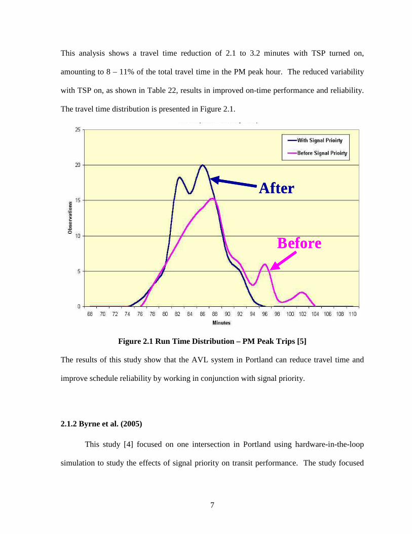
This analysis shows a travel time reduction of 2.1 to 3.2 minutes with TSP turned on,
amounting to 8 – 11% of the total travel time in the PM peak hour. The reduced variability
with TSP on, as shown in Table 22, results in improved on-time performance and reliability.
The travel time distribution is presented in Figure 2.1.
Before
After
Before Before
After After
Figure 2.1 Run Time Distribution – PM Peak Trips [5] The results of this study show that the AVL system in Portland can reduce travel time and
improve schedule reliability by working in conjunction with signal priority.
2.1.2 Byrne et al. (2005)
This study [4] focused on one intersection in Portland using hardware-in-the-loop
simulation to study the effects of signal priority on transit performance. The study focused

8
specifically on bus stop placement to address whether a green extension plan should be used
if there is passenger activity at a nearside stop. Four scenarios, nearside stops without TSP,
nearside stops with TSP, farside stops without TSP, and farside stops with TSP, were studied
and also broken down further into green extension or red truncation plans. These scenarios
were evaluated using actual field conditions and a combination of simulation software
(VISSIM) and a field signal controller at an actual intersection in Portland.
The results of the travel time analysis are provided in Table 2.3. These results
demonstrate that TSP provides a travel time benefit to farside stops with TSP, but may
reduce performance for nearside stops. Table 2.4 summarizes the researchers’ findings on
delay. The bus stop placement without TSP yields similar results for average delay and
standard deviation. The authors hypothesize that this similar control delay may be related to
an adjacent queue preventing vehicle re-entry into the traffic stream. These results also
indicate that TSP provides a benefit to farside stops but has the potential to negatively affect
bus delay at nearside stops. Furthermore, a comparison of the standard deviation is useful in
evaluating travel time variability. As seen in Table 2.4, that authors note that implementation
of TSP at farside bus stops considerably reduces standard deviation and thus reduces that
potential for buses to fall behind schedule. Overall, this research has demonstrated a 33%
reduction in signal delay when TSP is used at farside stops and an increase in delay at
nearside stops.
Table 2.3 Travel Times per Bus Simulation Results [4]
NearSide without TSP
FarSide without TSP
NearSide with TSP
FarSide with TSP
Average Bus Travel Time (Sec.)
79.1 76.8 84.1 68.3

9
Table 2.4 Simulation Results for Delay per Bus [4] NearSide FarSide w/o TSP w/ TSP w/o TSP w/ TSP Bus Delay (s)
Overall Delay Savings (s) Delay (s)
Overall Delay Savings (s)
Average (NB/SB) 27.6 32.5 +4.9 25.2 16.7 -8.5 Standard Deviation 5.34 5.56 5.18 2.05
2.1.3 Kimpel et al. (2005)
A study [6] conducted by researchers at Portland State University evaluated the
impacts of TSP on running time variability using AVL data. The data was collected on six
TriMet bus routes in 2001-2002 with no TSP and 2002-2003 after TSP implementation.
During these data collection periods, the threshold for activating signal priority was 90
seconds late and has since been reduced to 30 seconds. The overall results showed a
negligible decrease from 33.2 to 33.1 minutes of mean actual running time following TSP
implementation. Though two, outbound, PM routes showed substantial reductions in running
time. For running time variation, 11 of the 24 analysis segments showed a statistically
significant difference; four showing a decrease and seven experiencing an increase following
TSP implementation. These mixed results in bus performance did not find any “across-the-
board” benefits following TSP implementation. However, this study did not isolate the effect
of traffic and ridership growth from year to year. Changes in peak periods, net increases in
ridership, and changes in running time variability on other routes were not addressed.

10
2.2 Other TSP Research
This section focuses on non-Portland TSP research. The focus of many of these
studies is on bus stop placement and travel speed and schedule adherence evaluations. Other
studies that pertain to this research such as traffic volumes and TSP interaction are also
highlighted.
2.2.1 Liao and Davis (2007)
This paper [7] studied adaptive signal priority for a bus route in Minneapolis through
micro-simulation. As presented in Figure 2.2, their results indicate that a 12-15% reduction
in bus travel time during the AM peak period and a 4-11% reduction in travel time during the
PM peak periods are achievable through signal priority. The authors believe that lower
reduction in travel time during the PM peak period is due to the bus stop locations. Their
study corridor consisted mainly of nearside bus stops that were blocked by longer queues in
the PM peak period. The intersection queues also caused the bus to wait longer to find an
acceptable gap in order to rejoin the traffic. The priority request was beneficial however, in
that it helped clear the queue to provide service and reduce the bus clearance time.

11
Figure 2.2 AM and PM Peak Bus Speed and Travel Time [7]
2.2.2 Ngan, Sayed, and Abdelfatah (2004)
This research [8] studied signal priority on the 98 B-line bus route in Vancouver, BC
using VISSIM micro-simulation software. The researchers found that TSP is most effective
under moderate-to-heavy traffic conditions. Bus performance with TSP, as measured by
travel time, decreases as traffic volumes, thus encountering lower traffic delay. This is
demonstrated in Figure 2.3.

12
Figure 2.3 Impact on Bus Travel Time [8] The study also found an impact from bus stop location on bus performance. As
illustrated in Figure 2.4, a nearside bus stop causes higher delay to the study corridor buses
than far side bus stops. This is due to a significant portion of the green extension is wasted
during passenger loading and unloading. The authors note that it is possible to address some
of the nearside ineffectiveness through using delay times if dwell time at a bus stop is
consistent or placing the call immediately downstream of the stop.

13
Figure 2.4 Bus Stop Location Impact on Average Bus Delay (with TSP) [8]
FIGURE 2.5 shows the percentage increase in bus delay on the study corridor when moving
bus stops from the farside to the nearside of an intersection.
Figure 2.5 Nearside Bus Stop Impact on TSP Effectiveness [8] Finally, the authors also noted that removing signal coordination from a corridor increases
the entire corridor delay, attributed to an increase in the main street delay. Only minimal
improvements were found on the cross streets when removing coordination since green time
for the cross streets is maintained when there is no TSP call.
14
2.2.3 Muthuswamy, McShane, and Daniel (2006)
This study [3] used simulation to study TSP on a study corridor in Newark, NJ. IT
found that the benefits of TSP are not uniform along a corridor and that at cross streets with
heavy traffic volumes, TSP should be restricted or suppressed to avoid excessive delays at
these cross streets.
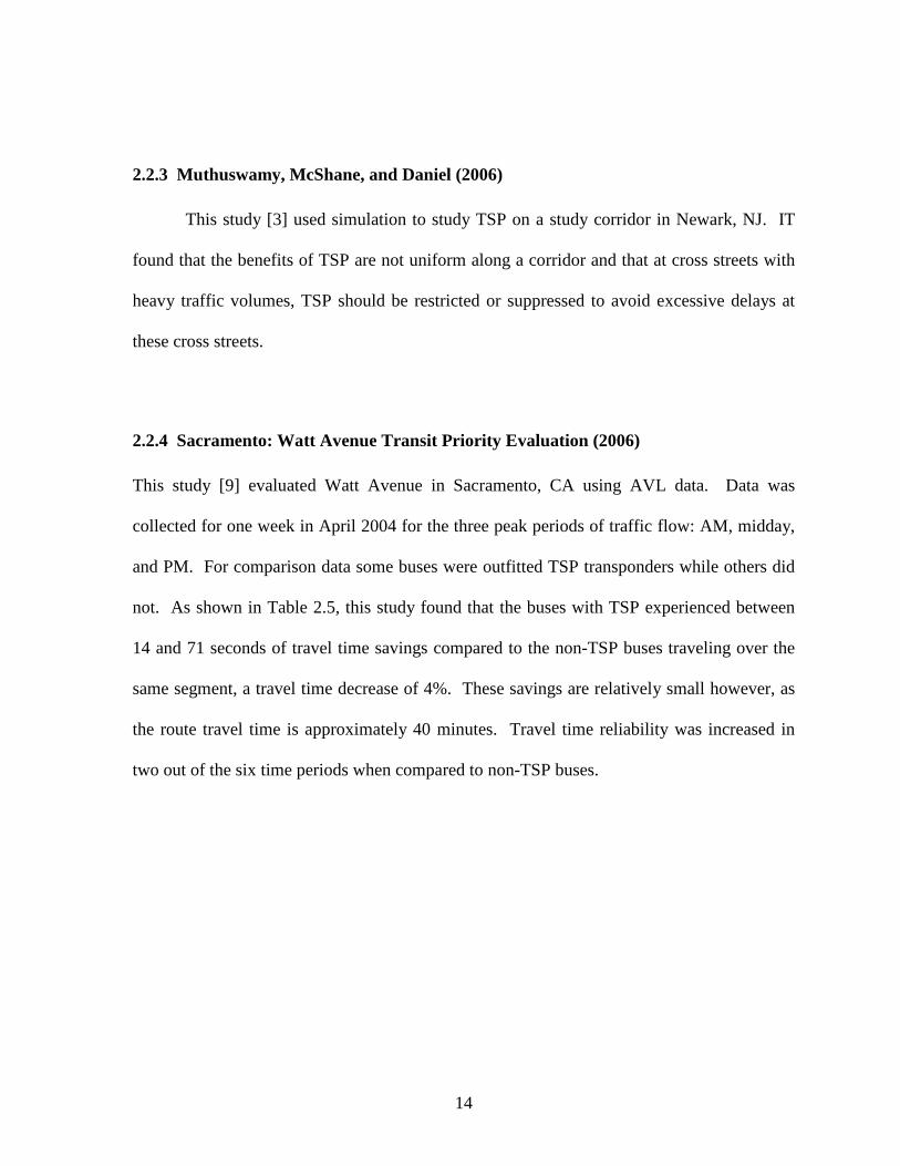
2.2.4 Sacramento: Watt Avenue Transit Priority Evaluation (2006)
This study [9] evaluated Watt Avenue in Sacramento, CA using AVL data. Data was
collected for one week in April 2004 for the three peak periods of traffic flow: AM, midday,
and PM. For comparison data some buses were outfitted TSP transponders while others did
not. As shown in Table 2.5, this study found that the buses with TSP experienced between
14 and 71 seconds of travel time savings compared to the non-TSP buses traveling over the
same segment, a travel time decrease of 4%. These savings are relatively small however, as
the route travel time is approximately 40 minutes. Travel time reliability was increased in
two out of the six time periods when compared to non-TSP buses.

15
Table 2.5 Travel Times for TSP and Non-TSP Buses, All Segments [9]
2.2.5 Virginia Tech Transit Signal Priority Evaluation (2006)
This report [10] studied a corridor in the Northern Virginia area to evaluate the
benefits of basic green-extension TSP using field-collected GPS data. Results showed
overall travel time improvements of 3% to 6% and presented in table 2.6. The study also
found that the TSP strategies reduced transit-vehicle intersection delay by as much as 23%.
In addition, the field study found that TSP benefits were maximized under moderate to low
levels of congestion. Bus stop location was also studied in simulation and found that near-
side bus stops resulted in increased system-wide delays of 2.85% over non-TSP operations,
while mid-block and far-side bus stops resulted in network-wide savings of 1.62%.

16
Table 2.6 Detailed Travel Time Results [10]
2.2.6 98 B-Line Bus Rapid Transit Evaluation Study (2003)
This evaluation [11] studied the 98 B-Line, an approximately 8 mile bus corridor
from the Airport to Downtown Vancouver, BC. Data was collected from buses with AVL
systems and an active TSP system and compared to recent, manually collected data prior to
TSP implementation. The results found only small differences in bus travel time in the
before and after data as presented in Table 2.7. However, the results suggest that the TSP
system has made travel times less variable, as measured by the standard deviation, by 40 –
50%.
Table 2.7 Travel Time Statistics, Airport Station – West Hastings Street [11]

17
Schedule adherence data with and without TSP was compared to determine the impact of
TSP on service reliability. In the Downtown Vancouver section, the variability of schedule
adherence has decreased with TSP throughout the day in the southbound direction and during
the mid-day in the northbound direction, demonstrating the improved performance from TSP
on this corridor. The schedule adherence results are presented in Table 2.8.
Table 2.8 Schedule Adherence Statistics Downtown Vancouver Section [11]
2.2.7 Garrow and Machemehl (1997)
This study [12] investigated TSP using CORSIM micro-simulation to study the effect
of TSP on the surrounding traffic environment. They found that signal priority is often
justified during non-peak periods but that there are severe negative impacts on the cross-
street traffic during peak periods--specifically, if the cross-street saturation level is above 1.0
with a 10-second green extension or above 0.9 with a 20-second green extension. Therefore,
the authors suggest that TSP is only justified during peak periods when the level of transit

18
usage is high. The results are shown in Table 2.9. This is relevant to the 82nd Avenue study
corridor as it has several intersections with high-volume east-west arterials connecting to
Downtown Portland.
Table 2.9 Negative Impacts Accruing on Cross-Streets Due to Signal Priority (Assumed Bus Headway = 10 minutes) [12]
Cross Street Saturation Green Extension = 10 sec. Green Extension = 20 sec.
Saturation Level = 0.8 Minimal Moderate Saturation Level = 0.9 Moderate Significant Saturation Level = 1.0 Significant Significant
2.3 Literature Review Summary
This chapter identified several studies relating to the effectiveness of transit signal
priority. This review of the relevant research focused on travel speed and schedule
adherence as measures of effectiveness of these systems. The results of this review found
mixed results on the benefits of TSP investment. The Vancouver studies and Minneapolis
study are among cities that have found a great benefit in travel time and, more importantly,
schedule reliability. Portland studies have found mixed results with signal priority, however
no evaluation of the system has been performed since the signal priority threshold has been
reduced to 30 seconds. Other cities, such as Sacramento, have not found as a great a benefit
after TSP implementation. One reason for this reduced performance can be linked to bus
stop placement; the literature overwhelmingly supports farside bus stop placement over
nearside placement. This is due to several reasons, most importantly that uneven dwell times
at stops as well as queues not allowing buses back into the traffic stream. Finally, the
Garrow and Muthuswamy studies both found great disbenefits of TSP at intersections with
high volume roadways.

19
CHAPTER 3
FIELD DATA COLLECTION AND PROCESSING
The data collection portion of this evaluation took place on a two mile corridor of the
Number 72 bus route traveling along NE/SE 82nd Avenue in Portland, Oregon. The data
collection occurred over two, two-week periods in July and August, 2007 during which there
were no significant events or holidays.
This chapter will focus on the processes and methodology used for collecting data for
this project. It is divided into sections covering the Study Corridor, Field Data Collection,
Field Data Processing and Quality Control. The Field Data Collection section is divided into
information on the Automatic Vehicle Locator system and the Conditional Priority System.
3.1 Study Corridor
The study corridor of NE/SE 82nd Avenue, also designated as State Highway 213,
was chosen due to the high bus ridership and its function as a major north/south arterial. Bus
route 72 has the highest bus ridership in TriMet’s system [13] and 82nd Avenue has an AADT
of approximately 29,000 in 2007. [14] Therefore, this corridor provides a characteristic
representation of TriMet’s bus routes within the City of Portland. As demonstrated in Figure
3.1, the 2 mile corridor length includes 16 northbound and 16 southbound bus stops and 9
signalized intersections. The corridor is bound to the north by NE Hassolo Street, just south
of a transfer station with TriMet’s Blue and Red MAX light rail lines, and to the south by SE
Woodward Street.


21
3.1.1 Corridor Conditions
This corridor is a major arterial serving several developing neighborhoods and
business districts. The roadway section is 60 feet wide curb to curb consisting of two travel
lanes in each direction and a continuous center turn lane. Narrow sidewalks exist on both
sides that are typically six feet wide and impeded with signs and utility poles. The speed
limit is posted at 35 miles-per-hour. Generally, the development patterns along this corridor
are auto-centric with large set-backs and non-shared driveways.
Figure 3.2 NE 82nd Avenue in Portland, Oregon [photo: Jonathan Maus, BikePortland.org]
This route has a large pedestrian population due to many senior housing facilities and
a large lower income population, contributing to a very high public transit use. The corridor
is also a location for many destinations as well as transfer points to all east-west bus lines
running downtown. [13]

22
3.2 Field Data Collection
The field data was recorded during two, two-week time periods, one with the TSP on
and the other with the TSP turned off. These periods were July 22 – August 4, 2007 and
August 12 – August 25, 2007, for the TSP on and off, respectively. The data collection
periods each began on a Saturday and ended on a Sunday and had no scheduled significant
events or holidays. Real time data of the buses as they moved through the corridor was
collected through Global Positioning System (GPS) enabled busses that monitored the
vehicle location and transmitted this information wirelessly to the transit control center.
3.2.1 Automatic Vehicle Location System
TriMet implements TSP through the transit system’s automatic vehicle location
(AVL) system. This AVL system, installed on all buses in the fleet, monitors and controls
bus operations through on-board GPS receivers and is connected to a Bus Dispatch System
(BDS). The BDS is connected to an on-board computer containing the bus’s route and
schedule information allowing to bus to determine schedule status on a real-time basis. With
this system, the buses send time-stamped vehicle location coordinates in real time to the
transit control center. This data is archived and also enhances the transit quality of service by
providing riders accurate information about bus arrival times at stops. Travel time and
average travel speed between stops as well as the vehicle’s schedule status (whether it is late,
on time, or early) according to that vehicle’s schedule can also be calculated from the time-
stamped location information from the buses. Data on dwell time, which doors opened, and
the number of passengers entering and exiting the buses are also collected and transmitted
with the location information. [4]

23
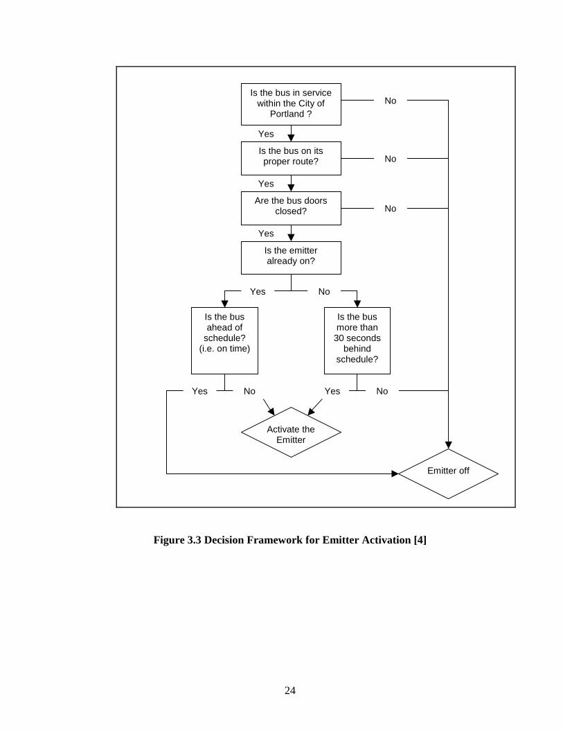
3.2.2 Conditional Priority System
The AVL system permits “smart” buses that are able to selectively request signal
priority. TriMet has implemented TSP using conditional priority that is dependent on the
status of the bus with respect to its schedule and if certain other criteria are met. These
criteria include the following and are summarized in Figure 3.3:
• The bus is within the City of Portland. Signals outside of the City boundary are not connected to the system.
• The bus is in route and in service.
• The bus is ready to proceed along the route. This is determined by whether the doors are open or closed.
• The bus is 30 seconds or more behind schedule.
24
Yes
Yes
Yes
Is the bus in service within the City of
Portland ?
Is the bus on its proper route? No
Are the bus doors closed?
Is the bus more than
30 seconds behind
schedule?
Activate the Emitter
Emitter off
Is the bus ahead of
schedule? (i.e. on time)
Is the emitter already on?
Yes No
Yes No
No
Yes No
No
Figure 3.3 Decision Framework for Emitter Activation [4]

25
If these conditions are all satisfied, the bus will activate the Opticon infrared emitter
to request priority. The City of Portland uses Wapiti Microsystems Software as their traffic
signal software which provides a range of priority options. Priority can include red
truncation, green extension, or a combination of the two. Figure 3.4 shows the priority
strategy decision framework as implemented by the controller software.
Is a call received by the traffic signal?
Green status of signal for the bus?
Green Extension* Red Truncation
Yes No
* Green extension may include combination of red truncation for the next cycle
Figure 3.4 Decision Framework for TSP Strategy to Employ [4] The particular priority strategy is determined by when in the signal cycle the priority request
is received. Priority is implemented while keeping the corridor in coordination by adjusting
forceoffs and modifying coordination timing plans. [4] Figure 3.5 presents a graphical
representation of the general signal priority concept.

26
Figure 3.5 General Signal Priorty Concept [15]
3.3 Field Data Processing and Quality Control
3.3.1 Data Processing
The raw data was received as two separate data sets, one for TSP on period and one for
the TSP off period. Each data set has over 43,000 separate entries associated with a specific
segment and time. These entries contain 45 attributes including time, date, direction,
location, schedule, passenger load, dwell time, door openings, peak periods, trip number, and

27
speed information. This information was brought into Microsoft Access and Excel 2003 for
analysis.
Queries in Access grouped information for specific time periods by both the
northbound and southbound directions. These time periods include the AM peak, PM peak,
non-peak, and full day for weekdays, weekends, and the entire study period. Using this
query feature in Access, the grouped data was further analyzed for corridor travel time and
schedule adherence. The query results were then exported into Excel for statistical analysis.
3.3.2 Quality Control
Quality Control of the data performed on the data sets for the total time periods by
direction and TSP status. Travel time data was sorted in Excel by average vehicle speed and
each value was associated with a percentile and Z-value of the data set. The speeds were
then examined and any average travel speed greater than 40 mph was removed. Where the
TSP was turned off, these values all had a Z-value greater than 3.0 and accordingly, all the
data points greater than 3.0 for the slow travel speeds were also removed. The data for the
TSP on scenarios had no Z-values greater than 3.0, but the high travel speeds accounted for
approximately 0.5% of the data set. Therefore, approximately 0.5% was taken out of the
slow travel speeds as well. These outliers are attributed to GPS malfunction and as Table 3.1
shows, the amount of outliers removed accounted for no more than 1.1% of any data set. The
columns labeled border values are the nearest outlier values to the kept data points and the
max value is the highest or lowest outlier value. Table 3.2 shows the change in standard
deviation with little change in the mean.

28
Table 3.1 Travel Time Outlier Determination Border Value Max Value
Direction TSP Speed (mph) Z-Value Percentile Speed (mph)
NB OFF 60.6 3.51 0.4% 1786.4 7.5 3.88 99.7% 3.7 Total Percentile 0.7%
SB OFF 57.3 3.24 0.1% 174.7 7.7 3.07 99.0% 3.5 Total Percentile 1.1%
NB ON 40.6 1.65 0.5% 210.2 7.8 1.78 99.6% 1.2 Total Percentile 0.9%
SB ON 41.2 1.82 0.6% 203.8 7.4 2.11 99.6% 1.1 Total Percentile 1.0%
Table 3.2 Statistical Comparison of Travel Time Data Set With and Without Outliers Direction TSP Mean Std. Dev.
NB OFF With Outliers 514.8 113.2 Outliers Removed 514.9 98.2
SB OFF With Outliers 554.4 130.4 Outliers Removed 549.8 112.1
NB ON With Outliers 529.4 214.8 Outliers Removed 523.2 99.0
SB ON With Outliers 556.3 208.2 Outliers Removed 553.3 113.1
These outliers found in the travel time scenarios were associated and removed from
the schedule adherence data sets as well. As outlined in Table 3.3, the removal of the outliers
had little effect on mean.
Table 3.3 Statistical comparison of schedule adherence data set with and without outliers
Direction TSP Mean Std. Dev.
NB OFF With Outliers -7.8 78.5 Outliers Removed -8.3 77.7
SB OFF With Outliers -40.5 100.5 Outliers Removed -43.1 96.3
NB ON With Outliers -1.7 80.8 Outliers Removed -2.2 79.1
SB ON With Outliers -41.9 97.8 Outliers Removed -41.6 97.5

29
CHAPTER 4
ANALYSIS AND FINDINGS
This chapter discusses the analysis of the collected field data on 82nd Avenue. As
detailed in Chapter 3, the dataset contains over 43,000 data points for route segments for
each the TSP on and TSP off scenarios. First, the data were analyzed to determine whether
there is any difference in overall corridor average travel speeds for the with TSP on. Then,
this chapter explores the effect of TSP on the schedule adherence.
4.1 Travel Time
It is expected that signal priority will yield lower average travel times for buses along
a route than conventional signal systems. Average bus travel time through the study corridor
in both the northbound and southbound directions is calculated for the total study period as
well as by service day and time of day from the AVL data. Two descriptive statistics, the
mean and standard deviation, are examined to determine bus performance. The mean of a
lower travel time indicates a higher average travel speed. Lower standard deviation is an
indication of service reliability as the buses travel, and thus arrive, at a more consistent rate.
4.1.1 Northbound Travel Times
The means and standard deviations for selected time periods are shown and compared
between the two TSP scenarios in Table 4.1. Significance in the difference of means was
determined through a two-tailed t-test with a 95% confidence interval.

30
Table 4.1Travel Time Comparison: Northbound TSP
OFF ON SIGNIFICANT?
Mean (s) 514.9 523.2 NO Total Study Period Std Dev 98.2 99.0 Mean (s) 480.0 490.4 NO Weekday AM Peak Std Dev 63.1 79.2 Mean (s) 622.8 651.8 NO Weekday PM Peak Std Dev 87.6 94.2 Mean (s) 507.3 513.2 NO Weekday Non-Peak Std Dev 93.7 89.7 Mean (s) 502.9 507.0 NO Weekend Std Dev 96.5 91.3
As presented in Table ##, while the results show a lower travel time with the TSP
turned off for each time period, none of these differences were significant. This is an
unexpected result, as signal priority is designed to speed the movement of transit vehicles
through the corridor. In addition, the TSP appears to have an adverse effect on reliability as
the standard deviations are lower with the TSP turned off during the total and peak travel
periods.
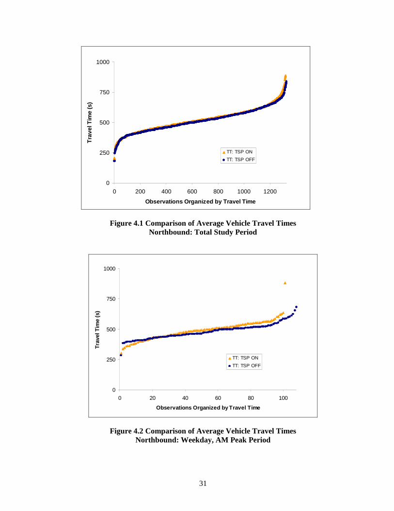
The following Figures 4.2-4.5 highlight the travel time differences with the TSP
turned on and off with the full range of observations during the principal time periods. These
observations have been organized by travel time to ease in direct comparison.
31
0
250
500
750
1000
0 200 400 600 800 1000 1200
Observations Organized by Travel Time
Tra
vel T
ime
(s)
TT: TSP ON
TT: TSP OFF
Figure 4.1 Comparison of Average Vehicle Travel Times Northbound: Total Study Period
0
250
500
750
1000
0 20 40 60 80 100
Observations Organized by Travel Time
Trav
el T
ime
(s)
TT: TSP ON
TT: TSP OFF
Figure 4.2 Comparison of Average Vehicle Travel Times Northbound: Weekday, AM Peak Period

32
0
250
500
750
1000
0 20 40 60 80 100 120
Observations Organized by Travel Time
Tra
vel T
ime
(s)
TT: TSP ON
TT: TSP OFF
Figure 4.3 Comparison of Average Vehicle Travel Times Northbound: Weekday, PM Peak Period
0
250
500
750
1000
0 200 400 600 800
Observations Organized by Travel Time
Tra
vel T
ime
(s)
TT: TSP ON
TT: TSP OFF
Figure 4.4 Comparison of Average Vehicle Travel Times Northbound: Weekday, Non-Peak Period

33
0
250
500
750
1000
0 50 100 150 200 250
Observations Organized by Travel Time
Tra
vel T
ime
(s)
TT: TSP ON
TT: TSP OFF
Figure 4.5 Comparison of Average Vehicle Travel Times Northbound: Weekend
Consistent with findings of a lack of significant difference between the means, these
figures show a similar relationship and distribution. There are only slight differences
between the two data sets which include a slightly greater range of travel times with the TSP
turned on and the TSP on data points typically fall slightly above the TSP data points.
Figures of additional time periods and individual scenarios are presented in Appendix
A.
4.1.2 Southbound Travel Times
The means and standard deviations for selected time periods are shown and compared
between the two TSP scenarios in Table 4.2. Significance in the difference of means was
determined through a two-tailed t-test with a 95% confidence interval.

34
Table 4.2 Travel Time Comparison: Southbound TSP
OFF ON SIGNIFICANT?
Mean (s) 549.8 553.3 NO Total Study Period Std Dev 112.1 113.1 Mean (s) 489.4 477.1 NO Weekday AM Peak Std Dev 69.9 85.2 Mean (s) 597.1 630.2 NO Weekday PM Peak Std Dev 104.7 95.8 Mean (s) 556.8 560.8 NO Weekday Non-Peak Std Dev 112.0 111.2 Mean (s) 526.7 524.5 NO Weekend Std Dev 112.0 111.9
As presented in Table ##, while the results show a lower travel time in most periods
with the TSP turned off, none of these differences were significant. Again, this result is
unexpected. Unlike in the northbound direction however, the standard deviation is lower in
the TSP on scenario is most cases. Although during the critical AM peak period and the total
study period, the standard deviation was lower in the TSP off scenarios. Therefore, while
the results are not as consistent, the TSP still appears to have an adverse effect on reliability
in several periods.
The following Figures 4.6-4.10 highlight the travel time differences with the TSP
turned on and off with the full range of observations during the principal time periods. These
observations have been organized by travel time to ease in direct comparison.

35
0
250
500
750
1000
0 200 400 600 800 1000 1200
Observations Organized by Travel Time
Tra
vel T
ime
(s)
TT: TSP ON
TT: TSP OFF
Figure 4.6 Comparison of Average Vehicle Travel Times Southbound: Total Study Period
0
250
500
750
1000
0 10 20 30 40
Observations
Tra
vel T
ime
(s)
TT: TSP ON
TT: TSP OFF
Figure 4.7 Comparison of Average Vehicle Travel Times Southbound: Weekday, AM Peak Period

36
0
250
500
750
1000
0 20 40 60 80
Observations Organized by Travel Time
Tra
vel T
ime
(s)
TT: TSP ON
TT: TSP OFF
Figure 4.8 Comparison of Average Vehicle Travel Times Southbound: Weekday, PM Peak Period
0
250
500
750
1000
0 100 200 300 400 500 600 700 800
Observations Organized by Travel Time
Tra
vel T
ime
(s)
TT: TSP ON
TT: TSP OFF
Figure 4.9 Comparison of Average Vehicle Travel Times Southbound: Weekday, Non-Peak Period

37
0
250
500
750
1000
0 50 100 150 200 250 300
Observations Organized by Travel Time
Tra
vel T
ime
(s)
TT: TSP ON
TT: TSP OFF
Figure 4.10 Comparison of Average Vehicle Travel Times Southbound: Weekend
Consistent with findings of a lack of significant difference between the means, these
figures show a similar relationship and distribution. There are only slight differences
between the two data sets which include a slightly greater range of travel times with the TSP
turned on and the TSP on data points typically fall slightly above the TSP data points.
Figures of additional time periods and individual scenarios are presented in Appendix
A.
4.2 Schedule Adherence
One of the benefits of signal priority is that it has been found to increase schedule
adherence and thus make transit more appealing to choice riders. In this study schedule
adherence was evaluated on the 82nd Avenue study corridor through an analysis of the AVL

38
data. This was performed through subtracting the seconds that the bus is behind schedule
when entering the corridor by the seconds that the bus is behind schedule when leaving the
corridor. This value is the amount of time that the bus is gaining in the corridor to minimize
schedule delays. Buses ahead of schedule is far worse than buses behind schedule but, as the
AVL data does not provide information about when the emitter is on or off, all data sets were
evaluated. To offset this unknown information, the results also examine the frequency of a
bus entering the corridor behind schedule becoming ahead of schedule. Buses were
considered behind schedule when they entered the corridor more than 30 seconds behind
schedule as this is the time that the emitter is turned on. When exiting the corridor, ahead of
schedule is considered any time before the scheduled stop. The same time periods as the
travel time analysis are highlighted in this section.
4.2.1 Northbound Schedule Adherence
The means and standard deviations for selected time periods are shown and compared
between the two TSP scenarios in Table 4.3; a negative number signifies the bus making up
time in the corridor, with respect to the schedule. Significance in the difference of means
was determined through a two-tailed t-test with a 95% confidence interval.

39
Table 4.3 Increase in Late Arrival Comparison: Northbound TSP
OFF ON SIGNIFICANT?
Mean (s) -8.3 -2.2 NO Total Study Period Std Dev 77.7 79.1 Mean (s) -2.2 11.1 NO Weekday AM Peak Std Dev 60.2 63.0 Mean (s) -7.8 18.1 NO Weekday PM Peak Std Dev 79.1 90.3 Mean (s) -13.3 -10.8 NO Weekday Non-Peak Std Dev 78.6 77.3 Mean (s) 2.5 6.7 NO Weekend Std Dev 79.7 80.6
As presented in Table 4.3, the results show an improvement in schedule difference
with the TSP turned off for each time period, however none of these differences were
significant. As with travel time, this result is unexpected, as conditional signal priority is
designed to improve schedule adherence.
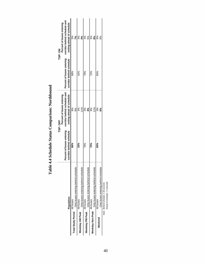
The goal of improving the late arrival rates is beneficial only until the scheduled
arrival time, after which it becomes unfavorable and reduced the quality of service. With the
conditional TSP system, the emitter turns off once the bus reaches its schedule arrival. Table
4.4 attempts to isolate the buses which had the emitter on through the corridor, taking into
account that the conditional priority system only provides priority once buses are at least 30
seconds behind schedule. The TSP off scenario similarly isolates these values for
comparison. The bolded values indicate greater performance.
40
Po
pu
lati
on
Per
cen
t o
f b
uses
en
teri
ng
corr
ido
r b
ehin
d s
ched
ule
Per
cent
of
bu
ses
ente
ring
co
rrid
or
beh
ind
sch
edul
e an
d
exit
ing
ahe
ad o
f sc
hed
ule
Per
cent
of
bus
es e
nter
ing
co
rrid
or
beh
ind
sch
edul
e
Per
cent
of
bu
ses
ente
ring
co
rrid
or
beh
ind
sch
edu
le a
nd
ex
itin
g a
hea
d o
f sc
hed
ule
All
buse
s66
%6%
68%
5%O
nly
buse
s en
terin
g be
hind
sch
edul
e9%
7%A
ll bu
ses
33%
4%42
%0%
Onl
y bu
ses
ente
ring
behi
nd s
ched
ule
11%
0%A
ll bu
ses
79%
3%79
%4%
Onl
y bu
ses
ente
ring
behi
nd s
ched
ule
4%5%
All
buse
s70
%8%
72%
5%O
nly
buse
s en
terin
g be
hind
sch
edul
e11
%8%
All
buse
s60
%4%
65%
6%O
nly
buse
s en
terin
g be
hind
sch
edul
e6%
9%N
ote:
Beh
ind
sche
dule
: ≥ 3
0 se
cond
s
Ahe
ad o
f sch
edul
e: <
0 s
econ
ds
Wee
kday
PM
Pea
k
Wee
kday
No
n-P
eak
Wee
kend
TS
P:
OF
F
To
tal S
tud
y P
erio
d
Wee
kday
AM
Pea
k
TS
P:
ON
Tab
le 4
.4 S
ched
ule
Sta
tus
Com
paris
on: N
orth
boun
d

41
As highlighted in Table 4.4, in all but the PM peak period, the TSP on scenario had a
greater percentage of buses entering the study corridor behind schedule. However, the TSP
on scenario recovered better in the total, AM peak, and non-peak periods as a lower
percentage of buses that entered the corridor late got ahead of schedule by the time they
exited the corridor.
The following Figures 4.11-4.15 highlight the schedule adherence changes through
the corridor with the TSP turned on and off with the full range of observations during the
principal time periods. These observations have been organized by travel time to ease in
direct comparison.
-400
-300
-200
-100
0
100
200
300
400
0 200 400 600 800 1000 1200
Observations Organized by Travel Time
Incr
ease
in L
ate
Arr
ival
(s)
Delay Increase: TSP ON
Delay Increase: TSP OFF
Figure 4.11 Comparison of Increase in Late Arrival to Schedule Through Corridor
Northbound: Total Study Period

42
-400
-300
-200
-100
0
100
200
300
400
0 20 40 60 80 100
Observations Organized by Travel Time
Incr
ease
in L
ate
Arr
ival
(s)
Delay Increase: TSP ON
Delay Increase: TSP OFF
Figure 4.12Comparison of Increase in Late Arrival to Schedule Through Corridor
Northbound: Weekday, AM Peak Period
-400
-300
-200
-100
0
100
200
300
400
0 20 40 60 80 100 120
Observations Organized by Travel Time
Incr
ease
in L
ate
Arr
ival
(s)
Delay Increase: TSP ON
Delay Increase: TSP OFF
Figure 4.13 Comparison of Increase in Late Arrival to Schedule Through Corridor
Northbound: Weekday, PM Peak Period

43
-400
-300
-200
-100
0
100
200
300
400
0 100 200 300 400 500 600 700
Observations Organized by Travel Time
Incr
ease
in L
ate
Arr
ival
(s)
Delay Increase: TSP ON
Delay Increase: TSP OFF
Figure 4.14 Comparison of Increase in Late Arrival to Schedule Through Corridor
Northbound: Weekday, Non-Peak Period
-400
-300
-200
-100
0
100
200
300
400
0 50 100 150 200 250
Observations Organized by Travel Time
Incr
ease
in L
ate
Arr
ival
(s)
Delay Increase: TSP ON
Delay Increase: TSP OFF
Figure 4.15 Comparison of Increase in Late Arrival to Schedule Through Corridor
Northbound: Weekend

44
Consistent with the findings of a lack of significant difference between the means,
these figures show a similar relationship and distribution. There are only slight differences
between the two data sets including a slightly greater range of schedule difference times with
the TSP turned on and the TSP on data points typically fall slightly above the TSP data
points, indicating less recovery from delayed vehicles.
Figures of additional time periods and individual scenarios are presented in Appendix
B.
4.2.2 Southbound Schedule Adherence
The means and standard deviations for selected time periods are shown and compared
between the two TSP scenarios in Table 4.5; a negative number signifies the bus making up
time in the corridor, with respect to the schedule. Significance in the difference of means
was determined through a two-tailed t-test with a 95% confidence interval.
Table 4.5 Increase in Late Arrival Comparison: Southbound TSP
OFF ON SIGNIFICANT?
Mean (s) -43.1 -41.6 NO Total Study Period Std Dev 96.3 97.5 Mean (s) 15.7 10.1 NO Weekday AM Peak Std Dev 58.4 74.4 Mean (s) -49.9 -20.2 NO Weekday PM Peak Std Dev 98.0 88.0 Mean (s) -40.6 -38.8 NO Weekday Non-Peak Std Dev 92.2 93.5 Mean (s) -58.3 -63.4 NO Weekend Std Dev 107.9 108.5
As presented in Table 4.5, the results show mixed results in schedule difference with
the TSP turned off and on for each time period, though none of the differences are found to

45
be significant. As with travel time, this result is unexpected, as conditional signal priority is
designed to improve schedule adherence.
The goal of improving the late arrival rates is beneficial only until the scheduled
arrival time, after which it becomes unfavorable and reduced the quality of service. With the
conditional TSP system, the emitter turns off once the bus reaches its schedule arrival. Table
4.6 attempts to isolate the buses which had the emitter on through the corridor, taking into
account that the conditional priority system only provides priority once buses are at least 30
seconds behind schedule. The TSP off scenario similarly isolates these values for
comparison. The bolded values indicate greater performance.

46
Po
pu
lati
on
Per
cen
t o
f b
uses
ent
erin
g
corr
ido
r b
ehin
d s
ched
ule
Per
cent
of
bus
es e
nte
ring
co
rrid
or
beh
ind
sch
edul
e an
d
exit
ing
ahe
ad o
f sc
hed
ule
Per
cent
of
bus
es e
nte
ring
co
rrid
or
beh
ind
sch
edul
e
Per
cent
of
bus
es e
nter
ing
co
rrid
or
beh
ind
sch
edul
e an
d
exit
ing
ahe
ad o
f sc
hed
ule
All
buse
s44
%8%
46%
10%
Onl
y bu
ses
ente
ring
behi
nd s
ched
ule
18%
22%
All
buse
s24
%0%
45%
2%O
nly
buse
s en
terin
g be
hind
sch
edul
e0%
5%A
ll bu
ses
43%
9%44
%4%
Onl
y bu
ses
ente
ring
behi
nd s
ched
ule
21%
9%A
ll bu
ses
46%
8%46
%10
%O
nly
buse
s en
terin
g be
hind
sch
edul
e19
%22
%A
ll bu
ses
43%
8%45
%13
%O
nly
buse
s en
terin
g be
hind
sch
edul
e18
%29
%N
ote:
Beh
ind
sche
dule
: ≥ 3
0 se
cond
s
Ahe
ad o
f sch
edul
e: <
0 s
econ
ds
TS
P:
OF
FT
SP
: O
N
To
tal S
tud
y P
erio
d
Wee
kday
AM
Pea
k
Wee
kday
PM
Pea
k
Wee
kday
No
n-P
eak
Wee
kend
Tab
le 4
.6 S
ched
ule
Sta
tus
Com
paris
on: S
outh
boun
d

47
As highlighted in Table 4.6, in all but the weekday non-peak period, the TSP on
scenario had a greater percentage of buses entering the study corridor behind schedule. The
TSP on scenario also recovered worse in all but the PM peak period as a higher percentage of
buses that entered the corridor late got ahead of schedule by the time they exited the corridor.
The following Figures 4.16-4.20 highlight the schedule adherence changes through
the corridor with the TSP turned on and off with the full range of observations during the
principal time periods. These observations have been organized by travel time to ease in
direct comparison.
-400
-300
-200
-100
0
100
200
300
400
0 200 400 600 800 1000 1200
Observations Organized by Travel Time
Incr
ease
in L
ate
Arr
ival
(s)
Delay Increase: TSP ON
Delay Increase: TSP OFF
Figure 4.16 Comparison of Increase in Late Arrival to Schedule Through Corridor
Southbound: Total Study Period

48
-400
-300
-200
-100
0
100
200
300
400
0 10 20 30 40
Observations Organized by Travel Time
Incr
ease
in L
ate
Arr
ival
(s)
Delay Increase: TSP ON
Delay Increase: TSP OFF
Figure 4.17 Comparison of Increase in Late Arrival to Schedule Through Corridor
Southbound: Weekday, AM Peak Period
-400
-300
-200
-100
0
100
200
300
400
0 10 20 30 40 50 60 70 80
Observations Organized by Travel Time
Incr
ease
in L
ate
Arr
ival
(s)
Delay Increase: TSP ON
Delay Increase: TSP OFF
Figure 4.18 Comparison of Increase in Late Arrival to Schedule Through Corridor
Southbound: Weekday, PM Peak Period
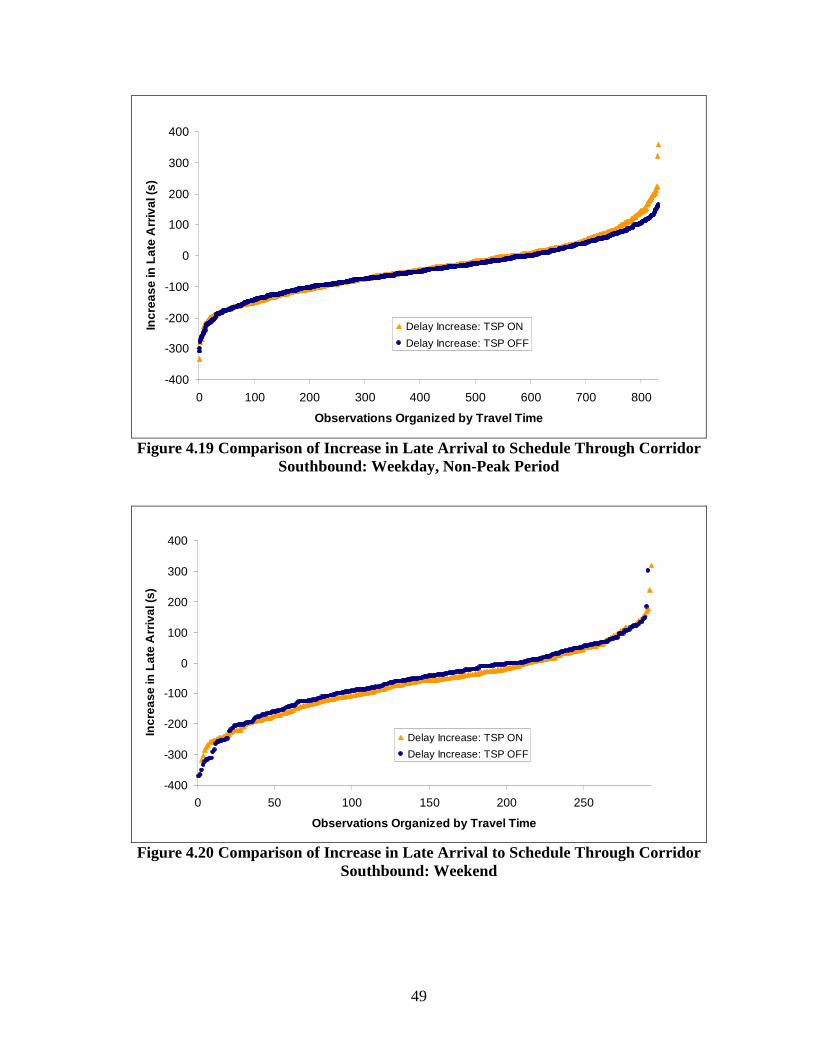
49
-400
-300
-200
-100
0
100
200
300
400
0 100 200 300 400 500 600 700 800
Observations Organized by Travel Time
Incr
ease
in L
ate
Arr
ival
(s)
Delay Increase: TSP ON
Delay Increase: TSP OFF
Figure 4.19 Comparison of Increase in Late Arrival to Schedule Through Corridor
Southbound: Weekday, Non-Peak Period
-400
-300
-200
-100
0
100
200
300
400
0 50 100 150 200 250
Observations Organized by Travel Time
Incr
ease
in L
ate
Arr
ival
(s)
Delay Increase: TSP ON
Delay Increase: TSP OFF
Figure 4.20 Comparison of Increase in Late Arrival to Schedule Through Corridor
Southbound: Weekend

50
Consistent with the findings of a lack of significant difference between the means,
these figures show a similar relationship and distribution.
Figures of additional time periods and individual scenarios are presented in Appendix
B.
4.3 Summary of Analysis and Findings
Chapter 4 of this report focused on the analysis and findings of the data collection of
this report. It was found that TSP provides no significant difference in travel times on this
corridor. It does however decrease reliability due to a higher standard deviation in travel
times in both directions. It was also found that there is no significant difference in schedule
adherence with TSP on this corridor. Additionally, there were mixed results for schedule
recovery with no clear benefit of TSP.

51
CHAPTER 5
CONCLUSIONS
Transit signal priority is often regarded as an effective way to increase the quality and
transit service through gains in travel speed and, more importantly, schedule reliability. This
reliability leads to an increase in choice riders and also has the advantage of more consistent
recovery times at the end of routes, reducing the number of buses needed to service a route.
This research has shown however, that on certain corridors there may be little to no benefit
towards TSP implementation and may possibly provide some disbenefit. These benefits of
transit signal priority were studied as the average bus operating speed and schedule
adherence on the. The direct comparison for TSP on and off scenarios completed for this
research yielded no significant differences in reduction in travel time or schedule adherence
performance. An additional interesting result was that the standard deviation of the results
did not have any specific tendencies with the TSP on or off. It was expected that the
standard deviation would be consistently lower with the TSP on, indicating improved
schedule reliability. Chapter 5 of this report will focus on conclusions drawn from the
research of this Portland bus corridor and improvements that could be made.
5.1 Bus Stop Placement
The literature review for this study highlights the impact of bus stop placement at
intersections on TSP. An examination of the study corridor reveals that out of all the bus
stops 44% occur at the nearside of a signalized intersection and 13% at the farside in the

52
northbound direction. In the southbound direction 31% of all bus stops are placed on the
nearside of signalized intersections and 19% on the farside. These placements are detailed in
Tables 5.1 and 5.2 and Figure 5.1.
Table 5.1 Bus Stop Positions – Northbound Direction: NB Length: 10480 ft Stop Location Stop ID Block Position Signalized?
SE 82nd & Woodward 8061 Near-Side Yes SE 82nd & Clinton 7947 Near-Side No SE 82nd & Division 7957 Near-Side Yes 2200 Block SE 82nd 7922 Mid-Block N/A SE 82nd & Mill 8007 Near-Side Yes SE 82nd & Hawthorne 7979 Near-Side No SE 82nd & Salmon 8037 Far-Side No SE 82nd & Yamhill 8065 Near-Side Yes SE 82nd & Washington 7928 Near-Side Yes SE 82nd & Stark 8047 Far-Side Yes SE 82nd & Ash 7930 Near-Side No SE 82nd & E Burnside 7936 Near-Side Yes NE 82nd & Davis 7955 Near-Side Yes NE 82nd & Glisan 7972 Far-Side Yes NE 82nd & Oregon 8014 Mid-Block N/A NE 82nd & Holladay 7987 Mid-Block N/A
% Nearside Stops: 63% % Nearside Stops & Signalized: 44% % Farside Stops: 19% % Farside Stops & Signalized: 13%

53
Table 5.2 Bus Stop Positions – Southbound Direction: SB Length: 10860 ft Stop Location Stop ID Intersection Position Signalized?
NE 82nd & Hassalo 7978 Mid-Block N/A NE 82nd & Pacific 7932 Mid-Block N/A NE 82nd & Glisan 7973 Near-Side Yes NE 82nd & Davis 7956 Near-Side Yes NE 82nd & E Burnside 7937 Near-Side Yes SE 82nd & Ash 7931 Far-Side No SE 82nd & Stark 8048 Near-Side Yes SE 82nd & Alder 7929 Near-Side No SE 82nd & Yamhill 8066 Far-Side Yes SE 82nd & Main 8004 Near-Side No SE 82nd & Hawthorne 7980 Near-Side No SE 82nd & Mill 8008 Far-Side Yes 2200 Block SE 82nd 7923 Mid-Block N/A SE 82nd & Division 7958 Near-Side Yes SE 82nd & Clinton 7948 Near-Side No SE 82nd & Woodward 8062 Far-Side Yes
% Nearside Stops: 56% % Nearside Stops & Signalized: 31% % Farside Stops: 25% % Farside Stops & Signalized: 19%
31%
44%
19%13%
0%
10%
20%
30%
40%
50%
Southbound
Northbound
Near-S ide
Far-S ide
Figure 5.1 Percentage of Bus Stops that are Located Nearside of a Signalized
Intersection

54
To account for potential changes in rider profile, the percentage of stops the buses
made was compared between scenarios. It is found that for the total study period the buses
stopped at 41% of the total stops with the TSP off and 43% of the stops with the TSP on in
both the northbound and southbound directions. These stop percentages, as well as the
percentages for other time periods shown in Figures 5.2 and 5.3, represent negligible
differences that would not account for much change in bus performance.
0%
10%
20%
30%
40%
50%
60%
Total WeekdayAM
WeekdayNP
WeekdayPM
Weekend
OFF
ON
Figure 5.2 Bus Stop Percentage - Northbound

55
0%
10%
20%
30%
40%
50%
60%
Total WeekdayAM
WeekdayNP
WeekdayPM
Weekend
OFFON
Figure 5.3 Bus Stop Percentage - Southbound
Relocation of the nearside stops would likely increase the effectiveness of the TSP
system. However, relocation may not be a feasible option for many of the locations since
they serve as transfer stops for east/west bus routes. These transfer stops are placed on the
same corner, such that the other route is on the farside, so that passenger amenities can be
combined and that riders do not have to cross the street. Therefore, other improvements must
be made to the system to improve the effectiveness. These improvements should be made to
the TSP algorithm to make decisions to not place a call at particular stops or to know when a
call has been received and will no longer be used. Improvements to the TSP system to
mitigate such bus stop placement problems include the following:
• Integrating the on-board stop request with the priority request relay to eliminate the
portion of ineffective plans occurring from passenger alighting. [5]

56
• To eliminate the ineffective plans that occur from passenger boarding, passenger
detection at stops could be installed. This is an expensive proposal however, that
would not be effective in all cases. [5]
• Eliminate extension plans at intersections with nearside stops. [5]
• Eliminate extension plans at nearside stops with high stop frequency through
examining AVL data that includes passenger counts.
5.2 Traffic Signal Timing and Cross-Street Traffic Considerations
Another explanation for the lack of TSP effectiveness on this corridor is delay from
the cross-streets with high traffic volumes. The two-mile corridor is intersected by three
east/west arterials (NE Glisan Street, SE Stark Street/SE Washington Street, and SE Division
Street) running between I-285 and Downtown.
As Garrow [12] has shown, during peak periods TSP can cause severe negative
impacts on cross-street traffic, particularly with high saturation levels. These impacts are
mitigated on intersecting arterials by adjusting the effective green ratio, g/C, to improve
traffic flow. The g/C ratio is then lower on the study corridor to accommodate the high
traffic volumes on the cross-streets. The minimum green times on the cross-streets are also
increased and thus reduce the amount of time that the priority call is able to “steal.” The high
pedestrian volume on 82nd Avenue, which contributes to the high bus ridership, also creates
limitations in signal timing as pedestrian calls occur frequently. Table 5.3, identifies these
limitations in signal timing that likely contribute to the unexpected performance.

57
Table 5.3 Traffic Signal Timing Considerations for Signal Priority [5] Parameter Limitation Comment
Pedestrian Detection
Lack of pedestrian detection (push buttons for actuation) requires the opposing pedestrian phase to time every cycle
Presence of pedestrian detection increases the potential responsiveness of the intersection to serve transit
Pedestrian Timing
Time for Flashing Don’t Walk can not be reduced in any case
Pedestrian detection reduces the need to recall pedestrian phases each cycle, thereby improving the responsiveness to transit
Multi-phase intersections
Phase skipping is not allowed in the State of Oregon, thus minimum vehicle times and clearance times must be considered for all phases (Legislative limitation)
Additional phases at intersections increase the amount of required time for service
Cycle lengths
Low cycle lengths reduce the flexibility of the engineer to extend the timing provided to the bus, although may provide better responsiveness overall
The tradeoff between flexibility and efficiency at the intersections has been consistently discussed, lower cycle length typically improves bus operations
5.3 Limitations of This Research
There were certain limitations with the research. Overall, the data set included a
tremendous amount of useful data that was well sorted. There are a couple of additional
attributes that should be added to the data set for further analysis. First, the data did not
include the TSP emitter status. This would be helpful to isolate the effect of TSP
performance through comparing it to bus runs when the emitter did not turn on. Bus driver
information is another attribute that should be included in the data set. This information
would allow for the analysis to account for drivers’ tendencies.
Another limitation of the research was the corridor length. A longer study corridor
would provide more accurate data for a bus route. This is because the longer travel times
would make the results less sensitive to variable dwell times and other delays.

58
5.4 Future Research Recommendations
There are several topics that future research should study. The first would be the
study the effect of the arterial cross-streets. These streets have high vehicular volumes and
bus routes that are also running TSP. How they interact and impact each other needs further
study. Another area of focus is to study the effect of eliminating extension plans at nearside
bus stops with frequent stops. This could be done through microsimulation of the corridor
using the bus stop rates in the AVL data. In both of these proposed studies, a longer corridor
length should be used that encompasses more major arterials and bus stops.

59
APPENDIX A
OFF_Dir0-AM_Trav
0
250
500
750
1000
0 20 40 60 80 100 120 140
Observations
Tra
vel
Tim
e (s
)
TT
Mean
-1 Std Dev
+1 Std Dev
Figure A.1 Northbound Vehicle Travel Times, AM Peak Period, TSP OFF
OFF_Dir0-AM_Trav-Wkday
0
250
500
750
1000
0 20 40 60 80 100
Observations
Tra
vel
Tim
e (s
)
TT
Mean
-1 Std Dev
+1 Std Dev
Figure A.2 Northbound Vehicle Travel Times, Weekday AM Peak Period, TSP OFF

60
OFF_Dir0-AM_Trav-Wkend
0
250
500
750
1000
0 10 20 30 40
Observations
Tra
vel
Tim
e (s
)
TT
Mean
-1 Std Dev
+1 Std Dev
Figure A.3 Northbound Vehicle Travel Times, Weekend AM Peak Period, TSP OFF
OFF_Dir0-NP_Trav
0
250
500
750
1000
0 200 400 600 800 1000
Observations
Tra
vel
Tim
e (s
)
TT
Mean
-1 Std Dev
+1 Std Dev
Figure A.4 Northbound Vehicle Travel Times, Non-Peak Period, TSP OFF

61
OFF_Dir0-NP_Trav-Wkday
0
250
500
750
1000
0 200 400 600 800
Observations
Tra
vel
Tim
e (s
)
TT
Mean
-1 Std Dev
+1 Std Dev
Figure A.5 Northbound Vehicle Travel Times, Weekday Non-Peak Period, TSP OFF
OFF_Dir0-NP_Trav-Wkend
0
250
500
750
1000
0 50 100 150 200
Observations
Tra
vel
Tim
e (s
)
TT
Mean
-1 Std Dev
+1 Std Dev
Figure A.6 Northbound Vehicle Travel Times, Weekend Non-Peak Period, TSP OFF

62
OFF_Dir0-PM_Trav
0
250
500
750
1000
0 20 40 60 80 100 120 140
Observations
Tra
vel
Tim
e (s
)
TT
Mean
-1 Std Dev
+1 Std Dev
Figure A.7 Northbound Vehicle Travel Times, PM Peak Period, TSP OFF
OFF_Dir0-PM_Trav-Wkday
0
250
500
750
1000
0 20 40 60 80 100 120
Observations
Tra
vel
Tim
e (s
)
TT
Mean
-1 Std Dev
+1 Std Dev
Figure A.8 Northbound Vehicle Travel Times, Weekday PM Peak Period, TSP OFF

63
OFF_Dir0-PM_Trav-Wkend
0
250
500
750
1000
0 5 10 15 20
Observations
Tra
vel
Tim
e (s
)
TT
Mean
-1 Std Dev
+1 Std Dev
Figure A.9 Northbound Vehicle Travel Times, Weekend PM Peak Period, TSP OFF
OFF_Dir0-TotalTrav
0
250
500
750
1000
0 200 400 600 800 1000 1200
Observations
Tra
vel
Tim
e (s
)
TT
Mean
-1 Std Dev
+1 Std Dev
Figure A.10 Northbound Vehicle Travel Times, Total Study Period, TSP OFF

64
OFF_Dir0-TotalTrav-Wkday
0
250
500
750
1000
0 200 400 600 800 1000
Observations
Tra
vel
Tim
e (s
)
TT
Mean
-1 Std Dev
+1 Std Dev
Figure A.11 Northbound Vehicle Travel Times, Weekday Total Study Period, TSP OFF
OFF_Dir0-TotalTrav-Wkend
0
250
500
750
1000
0 50 100 150 200 250
Observations
Tra
vel
Tim
e (s
)
TT
Mean
-1 Std Dev
+1 Std Dev
Figure A.12 Northbound Vehicle Travel Times, Weekend Total Study Period, TSP OFF

65
OFF_Dir1-AM_Trav
0
250
500
750
1000
0 10 20 30 40 50 60 70
Observations
Tra
vel
Tim
e (s
)
TT
Mean
-1 Std Dev
+1 Std Dev
Figure A.13 Southbound Vehicle Travel Times, AM Peak Period, TSP OFF
OFF_Dir1-AM_Trav-Wkday
0
250
500
750
1000
0 10 20 30 40
Observations
Tra
vel
Tim
e (s
)
TT
Mean
-1 Std Dev
+1 Std Dev
Figure A.14 Southbound Vehicle Travel Times, Weekday AM Peak Period, TSP OFF

66
OFF_Dir1-AM_Trav-Wkend
0
250
500
750
0 5 10 15 20
Observations
Tra
vel
Tim
e (s
)
TT
Mean
-1 Std Dev
+1 Std Dev
Figure A.15 Southbound Vehicle Travel Times, Weekend AM Peak Period, TSP OFF
OFF_Dir1-NP_Trav
0
250
500
750
1000
0 200 400 600 800 1000
Observations
Tra
vel
Tim
e (s
)
TT
Mean
-1 Std Dev
+1 Std Dev
Figure A.16 Southbound Vehicle Travel Times, Non-Peak Period, TSP OFF

67
OFF_Dir1-NP_Trav-Wkday
0
250
500
750
1000
0 200 400 600 800
Observations
Tra
vel
Tim
e (s
)
TT
Mean
-1 Std Dev
+1 Std Dev
Figure A.17 Southbound Vehicle Travel Times, Weekday Non-Peak Period, TSP OFF
OFF_Dir1-NP_Trav-Wkend
0
250
500
750
1000
0 50 100 150 200
Observations
Tra
vel
Tim
e (s
)
TT
Mean
-1 Std Dev
+1 Std Dev
Figure A.18 Southbound Vehicle Travel Times, Weekend Non-Peak Period, TSP OFF

68
OFF_Dir1-PM_Trav
0
250
500
750
1000
0 20 40 60 80 100
Observations
Tra
vel
Tim
e (s
)
TT
Mean
-1 Std Dev
+1 Std Dev
Figure A.19 Southbound Vehicle Travel Times, PM Peak Period, TSP OFF
OFF_Dir1-PM_Trav-Wkday
0
250
500
750
1000
0 20 40 60 80
Observations
Tra
vel
Tim
e (s
)
TT
Mean
-1 Std Dev
+1 Std Dev
Figure A.20 Southbound Vehicle Travel Times, Weekday PM Peak Period, TSP OFF

69
OFF_Dir1-PM_Trav-Wkend
0
250
500
750
1000
0 10 20 30
Observations
Tra
vel
Tim
e (s
)
TT
Mean
-1 Std Dev
+1 Std Dev
Figure A.21 Southbound Vehicle Travel Times, Weekend PM Peak Period, TSP OFF
OFF_Dir1-TotalTrav
0
250
500
750
1000
0 200 400 600 800 1000 1200
Observations
Tra
vel
Tim
e (s
)
TT
Mean
-1 Std Dev
+1 Std Dev
Figure A.22 Southbound Vehicle Travel Times, Total Study Period, TSP OFF

70
OFF_Dir1-TotalTrav-Wkday
0
250
500
750
1000
0 200 400 600 800
Observations
Tra
vel
Tim
e (s
)
TT
Mean
-1 Std Dev
+1 Std Dev
Figure A.23 Southbound Vehicle Travel Times, Weekday Total Study Period, TSP OFF
OFF_Dir1-TotalTrav-Wkend
0
250
500
750
1000
0 50 100 150 200 250
Observations
Tra
vel
Tim
e (s
)
TT
Mean
-1 Std Dev
+1 Std Dev
Figure A.24 Southbound Vehicle Travel Times, Weekend Total Study Period, TSP OFF

71
ON_Dir0-AM_Trav
0
250
500
750
1000
0 20 40 60 80 100 120 140
Observations
Tra
vel
Tim
e (s
)
TT
Mean
-1 Std Dev
+1 Std Dev
Figure A.25 Northbound Vehicle Travel Times, AM Peak Period, TSP ON
ON_Dir0-AM_Trav-Wkday
0
250
500
750
1000
0 20 40 60 80 100
Observations
Tra
vel
Tim
e (s
)
TT
Mean
-1 Std Dev
+1 Std Dev
Figure A.26 Northbound Vehicle Travel Times, Weekday AM Peak Period, TSP ON

72
ON_Dir0-AM_Trav-Wkend
0
250
500
750
1000
0 10 20 30 40
Observations
Tra
vel
Tim
e (s
)
TT
Mean
-1 Std Dev
+1 Std Dev
Figure A.27 Northbound Vehicle Travel Times, Weekend AM Peak Period, TSP ON
ON_Dir0-NP_Trav
0
250
500
750
1000
0 200 400 600 800 1000
Observations
Tra
vel
Tim
e (s
)
TT
Mean
-1 Std Dev
+1 Std Dev
Figure A.28 Northbound Vehicle Travel Times, Non-Peak Period, TSP ON

73
ON_Dir0-NP_Trav-Wkday
0
250
500
750
1000
0 100 200 300 400 500 600 700
Observations
Tra
vel
Tim
e (s
)
TT
Mean
-1 Std Dev
+1 Std Dev
Figure A.29 Northbound Vehicle Travel Times, Weekday Non-Peak Period, TSP ON
ON_Dir0-NP_Trav-Wkend
0
250
500
750
1000
0 50 100 150 200
Observations
Tra
vel
Tim
e (s
)
TT
Mean
-1 Std Dev
+1 Std Dev
Figure A.30 Northbound Vehicle Travel Times, Weekend Non-Peak Period, TSP ON

74
ON_Dir0-PM_Trav
0
250
500
750
1000
0 20 40 60 80 100 120 140
Observations
Tra
vel
Tim
e (s
)
TT
Mean
-1 Std Dev
+1 Std Dev
Figure A.31 Northbound Vehicle Travel Times, PM Peak Period, TSP ON
ON_Dir0-PM_Trav-Wkday
0
250
500
750
1000
0 20 40 60 80 100 120
Observations
Tra
vel
Tim
e (s
)
TT
Mean
-1 Std Dev
+1 Std Dev
Figure A.32 Northbound Vehicle Travel Times, Weekday PM Peak Period, TSP ON

75
ON_Dir0-PM_Trav-Wkend
0
250
500
750
1000
0 5 10 15 20 25
Observations
Tra
vel
Tim
e (s
)
TT
Mean
-1 Std Dev
+1 Std Dev
Figure A.33 Northbound Vehicle Travel Times, Weekend PM Peak Period, TSP ON
ON_Dir0-TotalTrav
0
250
500
750
1000
0 200 400 600 800 1000 1200
Observations
Tra
vel
Tim
e (s
)
TT
Mean
-1 Std Dev
+1 Std Dev
Figure A.34 Northbound Vehicle Travel Times, Total Study Period, TSP ON

76
ON_Dir0-TotalTrav-Wkday
0
250
500
750
1000
0 200 400 600 800 1000
Observations
Tra
vel
Tim
e (s
)
TT
Mean
-1 Std Dev
+1 Std Dev
Figure A.35 Northbound Vehicle Travel Times, Weekday Total Study Period, TSP ON
ON_Dir1-AM_Trav
0
250
500
750
1000
0 10 20 30 40 50 60 70
Observations
Tra
vel
Tim
e (s
)
TT
Mean
-1 Std Dev
+1 Std Dev
Figure A.36 Southbound Vehicle Travel Times, AM Peak Period, TSP ON

77
ON_Dir1-AM_Trav-Wkday
0
250
500
750
1000
0 10 20 30 40
Observations
Tra
vel
Tim
e (s
)
TT
Mean
-1 Std Dev
+1 Std Dev
Figure A.37 Southbound Vehicle Travel Times, Weekday AM Peak Period, TSP ON
ON_Dir1-AM_Trav-Wkend
0
250
500
750
1000
0 5 10 15 20
Observations
Tra
vel
Tim
e (s
)
TT
Mean
-1 Std Dev
+1 Std Dev
Figure A.38 Southbound Vehicle Travel Times, Weekend AM Peak Period, TSP ON

78
ON_Dir1-NP_Trav
0
250
500
750
1000
0 200 400 600 800 1000
Observations
Tra
vel
Tim
e (s
)
TT
Mean
-1 Std Dev
+1 Std Dev
Figure A.39 Southbound Vehicle Travel Times, Non-Peak Period, TSP ON
ON_Dir1-NP_Trav-Wkday
0
250
500
750
1000
0 200 400 600 800
Observations
Tra
vel
Tim
e (s
)
TT
Mean
-1 Std Dev
+1 Std Dev
Figure A.40 Southbound Vehicle Travel Times, Weekday Non-Peak Period, TSP ON

79
ON_Dir1-NP_Trav-Wkend
0
250
500
750
1000
0 50 100 150 200
Observations
Tra
vel
Tim
e (s
)
TT
Mean
-1 Std Dev
+1 Std Dev
Figure A.41 Southbound Vehicle Travel Times, Weekend Non-Peak Period, TSP ON
ON_Dir1-PM_Trav
0
250
500
750
1000
0 20 40 60 80 100
Observations
Tra
vel
Tim
e (s
)
TT
Mean
-1 Std Dev
+1 Std Dev
Figure A.42 Southbound Vehicle Travel Times, PM Peak Period, TSP ON

80
ON_Dir1-PM_Trav-Wkday
0
250
500
750
1000
0 10 20 30 40 50 60 70
Observations
Tra
vel
Tim
e (s
)
TT
Mean
-1 Std Dev
+1 Std Dev
Figure A.43 Southbound Vehicle Travel Times, Weekday PM Peak Period, TSP ON
ON_Dir1-PM_Trav-Wkend
0
250
500
750
1000
0 5 10 15 20 25 30
Observations
Tra
vel T
ime
(s)
TT
Mean
-1 Std Dev
+1 Std Dev
Figure A.44 Southbound Vehicle Travel Times, Weekend PM Peak Period, TSP ON

81
ON_Dir1-TotalTrav
0
250
500
750
1000
0 200 400 600 800 1000 1200
Observations
Tra
vel
Tim
e (s
)
TT
Mean
-1 Std Dev
+1 Std Dev
Figure A.45 Southbound Vehicle Travel Times, Total Study Period, TSP ON
ON_Dir1-TotalTrav-Wkday
0
250
500
750
1000
0 200 400 600 800
Observations
Tra
vel
Tim
e (s
)
TT
Mean
-1 Std Dev
+1 Std Dev
Figure A.46 Southbound Vehicle Travel Times, Weekday Total Study Period, TSP ON

82
ON_Dir1-TotalTrav-Wkend
0
250
500
750
1000
0 50 100 150 200 250 300
Observations
Tra
vel
Tim
e (s
)
TT
Mean
-1 Std Dev
+1 Std Dev
Figure A.47 Southbound Vehicle Travel Times, Weekend Total Study Period, TSP ON

83
APPENDIX B
Increase in Late Arrival to Schedule Through Corridor: OFF_Dir0_TimeDifference Total-AM
-400
-300
-200
-100
0
100
200
300
400
0 20 40 60 80 100 120 140
Observations
Incr
ease
in
Lat
e A
rriv
al (
s)
Delay Increase
Mean
-1 Std Dev
+1 Std Dev
Figure B.1 Increase in Late Arrival to Schedule Through Corridor
Northbound: AM Peak Period, TSP OFF
Increase in Late Arrival to Schedule Through Corridor: OFF_Dir0_TimeDifference Total-NP
-400
-300
-200
-100
0
100
200
300
400
0 200 400 600 800
Observations
Incr
ease
in
Lat
e A
rriv
al (
s)
Delay Increase
Mean
-1 Std Dev
+1 Std Dev
Figure B.2 Increase in Late Arrival to Schedule Through Corridor
Northbound: Non-Peak Period, TSP OFF

84
Increase in Late Arrival to Schedule Through Corridor: OFF_Dir0_TimeDifference Total-PM
-400
-300
-200
-100
0
100
200
300
400
0 20 40 60 80 100 120 140
Observations
Incr
ease
in
Lat
e A
rriv
al (
s)
Delay Increase
Mean
-1 Std Dev
+1 Std Dev
Figure B.3 Increase in Late Arrival to Schedule Through Corridor
Northbound: PM Peak Period, TSP OFF
Increase in Late Arrival to Schedule Through Corridor: OFF_Dir0_TimeDifference Weekday
-400
-300
-200
-100
0
100
200
300
400
0 200 400 600 800
Observations
Incr
ease
in
Lat
e A
rriv
al (
s)
Delay Increase
Mean
-1 Std Dev
+1 Std Dev
Figure B.4 Increase in Late Arrival to Schedule Through Corridor
Northbound: Weekday, TSP OFF

85
Increase in Late Arrival to Schedule Through Corridor: OFF_Dir0_TimeDifference Weekday-AM
-400
-300
-200
-100
0
100
200
300
400
0 20 40 60 80 100
Observations
Incr
ease
in
Lat
e A
rriv
al (
s)
Delay Increase
Mean
-1 Std Dev
+1 Std Dev
Figure B.5 Increase in Late Arrival to Schedule Through Corridor
Northbound: Weekday, AM Peak Period, TSP OFF
Increase in Late Arrival to Schedule Through Corridor: OFF_Dir0_TimeDifference Weekday-NP
-400
-300
-200
-100
0
100
200
300
400
0 100 200 300 400 500 600 700
Observations
Incr
ease
in
Lat
e A
rriv
al (
s)
Delay Increase
Mean
-1 Std Dev
+1 Std Dev
Figure B.6 Increase in Late Arrival to Schedule Through Corridor
Northbound: Weekday, Non-Peak Period, TSP OFF

86
Increase in Late Arrival to Schedule Through Corridor: OFF_Dir0_TimeDifference Weekday-PM
-400
-300
-200
-100
0
100
200
300
400
0 20 40 60 80 100 120
Observations
Incr
ease
in
Lat
e A
rriv
al (
s)
Delay Increase
Mean
-1 Std Dev
+1 Std Dev
Figure B.7 Increase in Late Arrival to Schedule Through Corridor
Northbound: Weekday, PM Peak Period, TSP OFF
Increase in Late Arrival to Schedule Through Corridor: OFF_Dir0_TimeDifference Weekend
-400
-300
-200
-100
0
100
200
300
400
0 50 100 150 200 250
Observations
Incr
ease
in
Lat
e A
rriv
al (
s)
Delay Increase
Mean
-1 Std Dev
+1 Std Dev
Figure B.8 Increase in Late Arrival to Schedule Through Corridor
Northbound: Weekend, TSP OFF

87
Increase in Late Arrival to Schedule Through Corridor: OFF_Dir0_TimeDifference Weekend-AM
-400
-300
-200
-100
0
100
200
300
400
0 5 10 15 20 25 30 35 40
Observations
Incr
ease
in
Lat
e A
rriv
al (
s)
Delay Increase
Mean
-1 Std Dev
+1 Std Dev
Figure B.9 Increase in Late Arrival to Schedule Through Corridor
Northbound: Weekend, AM Peak Period, TSP OFF
Increase in Late Arrival to Schedule Through Corridor: OFF_Dir0_TimeDifference Weekend-NP
-400
-300
-200
-100
0
100
200
300
400
0 50 100 150 200
Observations
Incr
ease
in
Lat
e A
rriv
al (
s)
Delay Increase
Mean
-1 Std Dev
+1 Std Dev
Figure B.10 Increase in Late Arrival to Schedule Through Corridor
Northbound: Weekend, Non-Peak Period, TSP OFF

88
Increase in Late Arrival to Schedule Through Corridor: OFF_Dir0_TimeDifference Weekend-PM
-400
-300
-200
-100
0
100
200
300
400
0 5 10 15 20
Observations
Incr
ease
in
Lat
e A
rriv
al (
s)
Delay Increase
Mean
-1 Std Dev
+1 Std Dev
Figure B.11 Increase in Late Arrival to Schedule Through Corridor
Northbound: Weekend, PM Peak Period, TSP OFF
Increase in Late Arrival to Schedule Through Corridor: OFF_Dir1_TimeDifference Total
-400
-300
-200
-100
0
100
200
300
400
0 200 400 600 800 1000 1200
Observations
Incr
ease
in
Lat
e A
rriv
al (
s)
Delay Increase
Mean
-1 Std Dev
+1 Std Dev
Figure B.12 Increase in Late Arrival to Schedule Through Corridor
Northbound: Total Study Period, TSP OFF

89
Increase in Late Arrival to Schedule Through Corridor: OFF_Dir1_TimeDifference Total-AM
-400
-300
-200
-100
0
100
200
300
400
0 10 20 30 40 50 60 70
Observations
Incr
ease
in
Lat
e A
rriv
al (
s)
Delay Increase
Mean
-1 Std Dev
+1 Std Dev
Figure B.13 Increase in Late Arrival to Schedule Through Corridor
Northbound: Total Study Period, AM Peak Period, TSP OFF
Increase in Late Arrival to Schedule Through Corridor: OFF_Dir1_TimeDifference Total-NP
-400
-300
-200
-100
0
100
200
300
400
0 200 400 600 800 1000
Observations
Incr
ease
in
Lat
e A
rriv
al (
s)
Delay Increase
Mean
-1 Std Dev
+1 Std Dev
Figure B.14 Increase in Late Arrival to Schedule Through Corridor
Northbound: Total Study Period, Non-Period, TSP OFF

90
Increase in Late Arrival to Schedule Through Corridor: OFF_Dir1_TimeDifference Total-PM
-400
-300
-200
-100
0
100
200
300
400
0 20 40 60 80 100
Observations
Incr
ease
in
Lat
e A
rriv
al (
s)
Delay Increase
Mean
-1 Std Dev
+1 Std Dev
Figure B.15 Increase in Late Arrival to Schedule Through Corridor
Northbound: Total Study Period, PM Peak Period, TSP OFF
Increase in Late Arrival to Schedule Through Corridor: OFF_Dir1_TimeDifference Weekday
-400
-300
-200
-100
0
100
200
300
400
0 200 400 600 800
Observations
Incr
ease
in L
ate
Arr
ival
(s)
Delay Increase
Mean
-1 Std Dev
+1 Std Dev
Figure B.16 Increase in Late Arrival to Schedule Through Corridor
Southbound: Weekday, TSP OFF

91
Increase in Late Arrival to Schedule Through Corridor: OFF_Dir1_TimeDifference Weekday-AM
-400
-300
-200
-100
0
100
200
300
400
0 10 20 30 40
Observations
Incr
ease
in
Lat
e A
rriv
al (
s)
Delay Increase
Mean
-1 Std Dev
+1 Std Dev
Figure B.17 Increase in Late Arrival to Schedule Through Corridor
Southbound: Weekday, AM Peak Period, TSP OFF
Increase in Late Arrival to Schedule Through Corridor: OFF_Dir1_TimeDifference Weekday-NP
-400
-300
-200
-100
0
100
200
300
400
0 200 400 600 800
Observations
Incr
eas
e in
Lat
e A
rriv
al (s
)
Delay Increase
Mean
-1 Std Dev
+1 Std Dev
Figure B.18 Increase in Late Arrival to Schedule Through Corridor
Southbound: Weekday, Non-Peak Period, TSP OFF

92
Increase in Late Arrival to Schedule Through Corridor: OFF_Dir1_TimeDifference Weekday-PM
-400
-300
-200
-100
0
100
200
300
400
0 10 20 30 40 50 60 70 80
Observations
Incr
ease
in
Lat
e A
rriv
al (
s)
Delay Increase
Mean
-1 Std Dev
+1 Std Dev
Figure B.19 Increase in Late Arrival to Schedule Through Corridor
Southbound: Weekday, PM Peak Period, TSP OFF
Increase in Late Arrival to Schedule Through Corridor: OFF_Dir1_TimeDifference Weekend
-400
-300
-200
-100
0
100
200
300
400
0 50 100 150 200 250
Observations
Incr
ease
in
Lat
e A
rriv
al (
s)
Delay Increase
Mean
-1 Std Dev
+1 Std Dev
Figure B.20 Increase in Late Arrival to Schedule Through Corridor
Southbound: Weekend, TSP OFF

93
Increase in Late Arrival to Schedule Through Corridor: OFF_Dir1_TimeDifference Weekend-AM
-400
-300
-200
-100
0
100
200
300
400
0 5 10 15 20
Observations
Incr
ease
in
Lat
e A
rriv
al (
s)
Delay Increase
Mean
-1 Std Dev
+1 Std Dev
Figure B.21 Increase in Late Arrival to Schedule Through Corridor
Southbound: Weekend, AM Peak Period, TSP OFF
Increase in Late Arrival to Schedule Through Corridor: OFF_Dir1_TimeDifference Weekend-NP
-400
-300
-200
-100
0
100
200
300
400
0 50 100 150 200
Observations
Incr
ease
in
Lat
e A
rriv
al (
s)
Delay Increase
Mean
-1 Std Dev
+1 Std Dev
Figure B.22 Increase in Late Arrival to Schedule Through Corridor
Southbound: Weekend, Non-Peak Period, TSP OFF

94
Increase in Late Arrival to Schedule Through Corridor: OFF_Dir1_TimeDifference Weekend-PM
-400
-300
-200
-100
0
100
200
300
400
0 5 10 15 20 25 30
Observations
Incr
ease
in
Lat
e A
rriv
al (
s)
Delay Increase
Mean
-1 Std Dev
+1 Std Dev
Figure B.23 Increase in Late Arrival to Schedule Through Corridor
Southbound: Weekend, PM Peak Period, TSP OFF
Increase in Late Arrival to Schedule Through Corridor: ON_Dir0_TimeDifference Total
-400
-300
-200
-100
0
100
200
300
400
0 200 400 600 800 1000 1200
Observations
Incr
ease
in L
ate
Arr
ival
(s)
Delay Increase
Mean
-1 Std Dev
+1 Std Dev
Figure B.24 Increase in Late Arrival to Schedule Through Corridor
Southbound: Total Study Period, TSP OFF

95
Increase in Late Arrival to Schedule Through Corridor: ON_Dir0_TimeDifference Total-AM
-400
-300
-200
-100
0
100
200
300
400
0 20 40 60 80 100 120
Observations
Incr
ease
in L
ate
Arr
ival
(s)
Delay Increase
Mean
-1 Std Dev
+1 Std Dev
Figure B.25 Increase in Late Arrival to Schedule Through Corridor
Southbound: Total Study Period, AM Peak Period, TSP OFF
Increase in Late Arrival to Schedule Through Corridor: ON_Dir0_TimeDifference Total-NP
-400
-300
-200
-100
0
100
200
300
400
500
0 200 400 600 800
Observations
Incr
eas
e in
Lat
e A
rriv
al (
s)
Delay Increase
Mean
-1 Std Dev
+1 Std Dev
Figure B.26 Increase in Late Arrival to Schedule Through Corridor
Southbound: Total Study Period, Non-Peak Period, TSP OFF

96
Increase in Late Arrival to Schedule Through Corridor: ON_Dir0_TimeDifference Total-PM
-400
-300
-200
-100
0
100
200
300
400
0 20 40 60 80 100 120 140
Observations
Incr
ease
in
Lat
e A
rriv
al (
s)
Delay Increase
Mean
-1 Std Dev
+1 Std Dev
Figure B.27 Increase in Late Arrival to Schedule Through Corridor
Southbound: Total Study Period, PM Peak Period, TSP OFF
Increase in Late Arrival to Schedule Through Corridor: ON_Dir0_TimeDifference Wkday
-400
-300
-200
-100
0
100
200
300
400
0 200 400 600 800
Observations
Incr
ease
in L
ate
Arr
ival
(s)
Delay Increase
Mean
-1 Std Dev
+1 Std Dev
Figure B.28 Increase in Late Arrival to Schedule Through Corridor
Northbound: Weekday TSP ON

97
Increase in Late Arrival to Schedule Through Corridor: ON_Dir0_TimeDifference Wkday-AM
-400
-300
-200
-100
0
100
200
300
400
0 10 20 30 40 50 60 70 80 90
Observations
Incr
ease
in
Lat
e A
rriv
al (
s)
Delay Increase
Mean
-1 Std Dev
+1 Std Dev
Figure B.29 Increase in Late Arrival to Schedule Through Corridor
Northbound: Weekday, AM Peak Period, TSP ON
Increase in Late Arrival to Schedule Through Corridor: ON_Dir0_TimeDifference Wkday-NP
-400
-300
-200
-100
0
100
200
300
400
0 100 200 300 400 500 600 700
Observations
Incr
ease
in
Lat
e A
rriv
al (
s)
Delay Increase
Mean
-1 Std Dev
+1 Std Dev
Figure B.30 Increase in Late Arrival to Schedule Through Corridor
Northbound: Weekday, Non-Peak Period, TSP ON

98
Increase in Late Arrival to Schedule Through Corridor: ON_Dir0_TimeDifference Wkday-PM
-400
-300
-200
-100
0
100
200
300
400
0 20 40 60 80 100 120
Observations
Incr
ease
in
Lat
e A
rriv
al (
s)
Delay Increase
Mean
-1 Std Dev
+1 Std Dev
Figure B.31 Increase in Late Arrival to Schedule Through Corridor
Northbound: Weekday, PM Peak Period, TSP ON
Increase in Late Arrival to Schedule Through Corridor: ON_Dir0_TimeDifference Wkend
-400
-300
-200
-100
0
100
200
300
400
0 50 100 150 200 250
Observations
Incr
ease
in
Lat
e A
rriv
al (
s)
Delay Increase
Mean
-1 Std Dev
+1 Std Dev
Figure B.32 Increase in Late Arrival to Schedule Through Corridor
Northbound: Weekend, TSP ON

99
Increase in Late Arrival to Schedule Through Corridor: ON_Dir0_TimeDifference Wkend-AM
-400
-300
-200
-100
0
100
200
300
400
0 5 10 15 20 25 30 35 40
Observations
Incr
ease
in
Lat
e A
rriv
al (
s)
Delay Increase
Mean
-1 Std Dev
+1 Std Dev
Figure B.33 Increase in Late Arrival to Schedule Through Corridor
Northbound: Weekend, AM Peak Period, TSP ON
Increase in Late Arrival to Schedule Through Corridor: ON_Dir0_TimeDifference Wkend-NP
-400
-300
-200
-100
0
100
200
300
400
0 50 100 150 200
Observations
Incr
ease
in
Lat
e A
rriv
al (
s)
Delay Increase
Mean
-1 Std Dev
+1 Std Dev
Figure B.34 Increase in Late Arrival to Schedule Through Corridor
Northbound: Weekend, Non-Peak Period, TSP ON

100
Increase in Late Arrival to Schedule Through Corridor: ON_Dir0_TimeDifference Wkend-PM
-400
-300
-200
-100
0
100
200
300
400
0 5 10 15 20
Observations
Incr
ease
in
Lat
e A
rriv
al (
s)
Delay Increase
Mean
-1 Std Dev
+1 Std Dev
Figure B.35 Increase in Late Arrival to Schedule Through Corridor
Northbound: Weekend, PM Peak Period, TSP ON
Increase in Late Arrival to Schedule Through Corridor: ON_Dir1_TimeDifference Total
-400
-300
-200
-100
0
100
200
300
400
0 200 400 600 800 1000 1200
Observations
Incr
ease
in L
ate
Arr
ival
(s)
Delay Increase
Mean
-1 Std Dev
+1 Std Dev
Figure B.36 Increase in Late Arrival to Schedule Through Corridor
Southbound: Total Study Period, TSP ON

101
Increase in Late Arrival to Schedule Through Corridor: ON_Dir1_TimeDifference Total-AM
-400
-300
-200
-100
0
100
200
300
400
0 10 20 30 40 50 60
Observations
Incr
ease
in L
ate
Arr
ival
(s)
Delay Increase
Mean
-1 Std Dev
+1 Std Dev
Figure B.37 Increase in Late Arrival to Schedule Through Corridor
Southbound: Total Study Period, AM Peak Period, TSP ON
Increase in Late Arrival to Schedule Through Corridor: ON_Dir1_TimeDifference Total-NP
-400
-300
-200
-100
0
100
200
300
400
0 200 400 600 800 1000
Observations
Incr
ease
in L
ate
Arr
ival
(s)
Delay Increase
Mean
-1 Std Dev
+1 Std Dev
Figure B.38 Increase in Late Arrival to Schedule Through Corridor
Southbound: Total Study Period, Non-Peak Period, TSP ON

102
Increase in Late Arrival to Schedule Through Corridor: ON_Dir1_TimeDifference Total-PM
-400
-300
-200
-100
0
100
200
300
400
0 20 40 60 80 100
Observations
Incr
ease
in L
ate
Arr
ival
(s)
Delay Increase
Mean
-1 Std Dev
+1 Std Dev
Figure B.39 Increase in Late Arrival to Schedule Through Corridor
Southbound: Total Study Period, PM Peak Period, TSP ON
Increase in Late Arrival to Schedule Through Corridor: ON_Dir1_TimeDifference Wkday
-400
-300
-200
-100
0
100
200
300
400
0 100 200 300 400 500 600 700 800 900
Observations
Incr
ease
in L
ate
Arr
ival
(s)
Delay Increase
Mean
-1 Std Dev
+1 Std Dev
Figure B.40 Increase in Late Arrival to Schedule Through Corridor
Southbound: Weekday, TSP ON

103
Increase in Late Arrival to Schedule Through Corridor: ON_Dir1_TimeDifference Wkday-AM
-400
-300
-200
-100
0
100
200
300
400
0 10 20 30 40
Observations
Incr
ease
in L
ate
Arr
ival
(s)
Delay Increase
Mean
-1 Std Dev
+1 Std Dev
Figure B.41 Increase in Late Arrival to Schedule Through Corridor
Southbound: Weekday, AM Peak Period, TSP ON
Increase in Late Arrival to Schedule Through Corridor: ON_Dir1_TimeDifference Wkday-NP
-400
-300
-200
-100
0
100
200
300
400
0 100 200 300 400 500 600 700 800
Observations
Incr
ease
in L
ate
Arr
ival
(s)
Delay Increase
Mean
-1 Std Dev
+1 Std Dev
Figure B.42 Increase in Late Arrival to Schedule Through Corridor
Southbound: Weekday, Non-Peak Period, TSP ON

104
Increase in Late Arrival to Schedule Through Corridor: ON_Dir1_TimeDifference Wkday-PM
-400
-300
-200
-100
0
100
200
300
400
0 10 20 30 40 50 60 70
Observations
Incr
ease
in L
ate
Arr
ival
(s)
Delay Increase
Mean
-1 Std Dev
+1 Std Dev
Figure B.43 Increase in Late Arrival to Schedule Through Corridor
Southbound: Weekday, PM Peak Period, TSP ON
Increase in Late Arrival to Schedule Through Corridor: ON_Dir1_TimeDifference Wkend
-400
-300
-200
-100
0
100
200
300
400
0 50 100 150 200 250
Observations
Incr
ease
in L
ate
Arr
ival
(s)
Delay Increase
Mean
-1 Std Dev
+1 Std Dev
Figure B.44 Increase in Late Arrival to Schedule Through Corridor
Southbound: Weekend, TSP ON

105
Increase in Late Arrival to Schedule Through Corridor: ON_Dir1_TimeDifference Wkend-AM
-400
-300
-200
-100
0
100
200
300
400
0 5 10 15 20
Observations
Incr
ease
in L
ate
Arr
ival
(s)
Delay Increase
Mean
-1 Std Dev
+1 Std Dev
Figure B.45 Increase in Late Arrival to Schedule Through Corridor
Southbound: Weekend, AM Peak Period, TSP ON
Increase in Late Arrival to Schedule Through Corridor: ON_Dir1_TimeDifference Wkend-NP
-400
-300
-200
-100
0
100
200
300
400
0 50 100 150 200
Observations
Incr
ease
in L
ate
Arr
ival
(s)
Delay Increase
Mean
-1 Std Dev
+1 Std Dev
Figure B.46 Increase in Late Arrival to Schedule Through Corridor
Southbound: Weekend, Non-Peak Period, TSP ON

106
Increase in Late Arrival to Schedule Through Corridor: ON_Dir1_TimeDifference Wkend-PM
-400
-300
-200
-100
0
100
200
300
400
0 5 10 15 20 25 30
Observations
Incr
ease
in L
ate
Arr
ival
(s)
Delay Increase
Mean
-1 Std Dev
+1 Std Dev
Figure B.47 Increase in Late Arrival to Schedule Through Corridor
Southbound: Weekend, PM Peak Period, TSP ON

107
REFERENCES
[1] Smith, H.R., B. Hemily, and M. Ivanovic. Transit Signal Priority (TSP): A Planning
and Implementation Handbook. FTA. U.S. Department of Transportation, 2005. [2] Advanced Traffic Management Systems Committee and Advanced Public
Transportation Systems Committee. Draft: An Overview of Transit Signal Priority. ITS America, April 15, 2002.
[3] Muthuswamy, S., W.R. McShane. and J.R. Daniel. “Evaluation of Transit Signal
Priority and Optimal Signal Timing Plans on Transit and Traffic Operations”. Transportation Research Board. Washington, DC. 2007.
[4] Byrne, N. et al. “Using Hardware-in-the-Loop Simulation to Evaluate Signal Control
Strategies for Transit Signal Priority”. Transportation Research Board. Washington, DC. 2005.
[5] Kittelson, W., et al. Portland Signal Priority: Technical Report. Kittelson and
Associates. 2003. [6] Kimpel, T.J., et al. “Analysis of Transit Signal Priority Using Archived TriMet Bus
Dispatch System Data”. Transportation Research Board. Washington, DC. 2005. [7] Liao, C., and G. A. Davis. “Simulation Study of Bus Signal Priority Strategy Based on
GPS-AVL and Wireless Communications”. Transportation Research Board. Washington, DC. 2007.
[8] Ngan, V., T. Sayed, and A Abdelfatah. Impacts of Various Traffic Parameters on
Transit Signal Priority Effectiveness. Journal of Public Transportation, Vol. 7, No. 3, 2004, pp. 71-93.
[9] Rephlo, J., and R. Haas. Sacramento-Watt Avenue Transit Priority and Mobility
Enhancement Demonstration Project: Phase III Evaluation Report. Report. FHWA, U.S. Department of Transportation, 1976.
[10] Rakha H. and K. Ahn. “Transit Signal Priority Project Phase II: Field and Simulation
Evaluation Results,” Virginia Tech Transportation Institute. 2006. [11] TransLink, Transport Canada, IBI Group. “98 B-Line Bus Rapid Transit Evaluation
Study”. 2003. [12] Garrow, M., and R. Machemehl. Development and Evaluation of Transit Signal
Priority Strategies. Southwest Region University Transportation Center, University of Texas, Austin, 1997.

108
[13] PDOT, 82nd Avenue of Roses, High Crash Corridor Safety Plan, Draft. Office of Transportation, City of Portland, OR. November 2007.
[14] PDOT, Traffic Count Database. www.portlandtransportation.org/
trafficcounts/default.htm. Accessed January 31, 2008.