Embed Size (px)
Citation preview
11th Canadian Masonry Symposium, Toronto, Ontario, May 31- June 3, 2009
EVALUATION OF YOUNG’S MODULUS FOR STONE MASONRY WALLS UNDER COMPRESSION
M.M. Sorour1, G.A. Parsekian2, D. Duchesne3, J. Paquette3, A. Mufti4, L. Jaeger5, and N.G.
Shrive6 1 PhD Candidate, Civil Engineering Department, University of Calgary, Canada; Lecturer assistant (on leave)
Faculty of Engineering, Cairo University, Cairo, Egypt, [email protected] 2Federal University of Sao Carlos, Sao Carlos, Sao Paulo, Brazil
3 Public Works and Government Services Canada 4Professor, University of Manitoba, Manitoba, Canada
5Professor Emeritus, Dalhousie University, Nova Scotia, Canada 6
Killam Memorial Professor, Civil Engineering Department, University of Calgary, Calgary, Canada
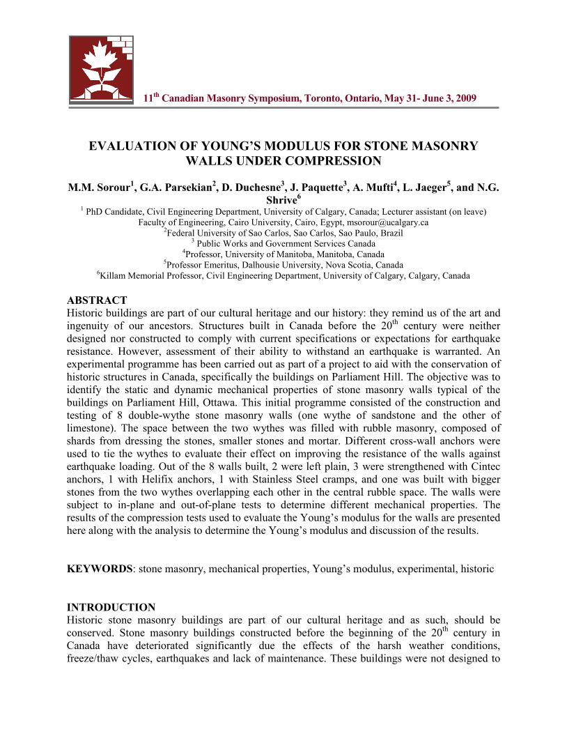
ABSTRACT Historic buildings are part of our cultural heritage and our history: they remind us of the art and ingenuity of our ancestors. Structures built in Canada before the 20th
INTRODUCTION
century were neither designed nor constructed to comply with current specifications or expectations for earthquake resistance. However, assessment of their ability to withstand an earthquake is warranted. An experimental programme has been carried out as part of a project to aid with the conservation of historic structures in Canada, specifically the buildings on Parliament Hill. The objective was to identify the static and dynamic mechanical properties of stone masonry walls typical of the buildings on Parliament Hill, Ottawa. This initial programme consisted of the construction and testing of 8 double-wythe stone masonry walls (one wythe of sandstone and the other of limestone). The space between the two wythes was filled with rubble masonry, composed of shards from dressing the stones, smaller stones and mortar. Different cross-wall anchors were used to tie the wythes to evaluate their effect on improving the resistance of the walls against earthquake loading. Out of the 8 walls built, 2 were left plain, 3 were strengthened with Cintec anchors, 1 with Helifix anchors, 1 with Stainless Steel cramps, and one was built with bigger stones from the two wythes overlapping each other in the central rubble space. The walls were subject to in-plane and out-of-plane tests to determine different mechanical properties. The results of the compression tests used to evaluate the Young’s modulus for the walls are presented here along with the analysis to determine the Young’s modulus and discussion of the results. KEYWORDS: stone masonry, mechanical properties, Young’s modulus, experimental, historic
Historic stone masonry buildings are part of our cultural heritage and as such, should be conserved. Stone masonry buildings constructed before the beginning of the 20th century in Canada have deteriorated significantly due the effects of the harsh weather conditions, freeze/thaw cycles, earthquakes and lack of maintenance. These buildings were not designed to
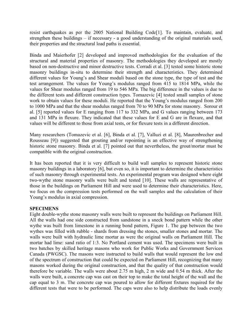
resist earthquakes as per the 2005 National Building Code[1]. To maintain, evaluate, and strengthen these buildings – if necessary - a good understanding of the original materials used, their properties and the structural load paths is essential. Binda and Maierhofer [2] developed and improved methodologies for the evaluation of the structural and material properties of masonry. The methodologies they developed are mostly based on non-destructive and minor destructive tests. Corradi et al. [3] tested some historic stone masonry buildings in-situ to determine their strength and characteristics. They determined different values for Young’s and Shear moduli based on the stone type, the type of test and the test arrangement. The values for Young’s modulus ranged from 415 to 1814 MPa, while the values for Shear modulus ranged from 19 to 546 MPa. The big difference in the values is due to the different tests and different construction types. Tomazevic [4] tested small samples of stone work to obtain values for these moduli. He reported that the Young’s modulus ranged from 200 to 1000 MPa and that the shear modulus ranged from 70 to 90 MPa for stone masonry. Sorour et al. [5] reported values for E ranging from 117 to 332 MPa, and G values ranging between 173 and 131 MPa in flexure. They indicated that these values for E and G are in flexure, and that values will be different to those from axial tests, or for flexure tests in a different direction. Many researchers (Tomazevic et al. [6], Binda et al. [7], Valluzi et al. [8], Maurenbrecher and Rousseau [9]) suggested that grouting and/or repointing is an effective way of strengthening historic stone masonry. Binda et al. [7] pointed out that nevertheless, the grout/mortar must be compatible with the original construction. It has been reported that it is very difficult to build wall samples to represent historic stone masonry buildings in a laboratory [6], but even so, it is important to determine the characteristics of such masonry through experimental tests. An experimental program was designed where eight two-wythe stone masonry walls were built and tested [10]. These walls are representative of those in the buildings on Parliament Hill and were used to determine their characteristics. Here, we focus on the compression tests performed on the wall samples and the calculation of their Young’s modulus in axial compression. SPECIMENS Eight double-wythe stone masonry walls were built to represent the buildings on Parliament Hill. All the walls had one side constructed from sandstone in a sneck bond pattern while the other wythe was built from limestone in a running bond pattern, Figure 1. The gap between the two wythes was filled with rubble - shards from dressing the stones, smaller stones and mortar. The walls were built with hydraulic lime mortar as were the original walls on Parliament Hill. The mortar had lime: sand ratio of 1:3. No Portland cement was used. The specimens were built in two batches by skilled heritage masons who work for Public Works and Government Services Canada (PWGSC). The masons were instructed to build walls that would represent the low end of the spectrum of construction that could be expected on Parliament Hill, recognizing that many masons worked during the original construction, and that the quality of that construction would therefore be variable. The walls were about 2.75 m high, 2 m wide and 0.54 m thick. After the walls were built, a concrete cap was cast on their top to make the total height of the wall and the cap equal to 3 m. The concrete cap was poured to allow for different fixtures required for the different tests that were to be performed. The caps were also to help distribute the loads evenly
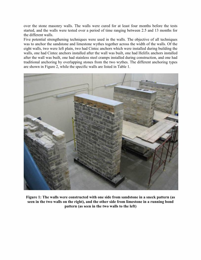
over the stone masonry walls. The walls were cured for at least four months before the tests started, and the walls were tested over a period of time ranging between 2.5 and 13 months for the different walls. Five potential strengthening techniques were used in the walls. The objective of all techniques was to anchor the sandstone and limestone wythes together across the width of the walls. Of the eight walls, two were left plain, two had Cintec anchors which were installed during building the walls, one had Cintec anchors installed after the wall was built, one had Helifix anchors installed after the wall was built, one had stainless steel cramps installed during construction, and one had traditional anchoring by overlapping stones from the two wythes. The different anchoring types are shown in Figure 2, while the specific walls are listed in Table 1.
Figure 1: The walls were constructed with one side from sandstone in a sneck pattern (as seen in the two walls on the right), and the other side from limestone in a running bond
pattern (as seen in the two walls to the left)
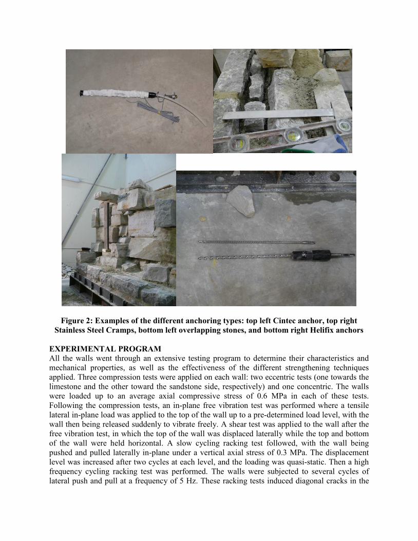
Figure 2: Examples of the different anchoring types: top left Cintec anchor, top right Stainless Steel Cramps, bottom left overlapping stones, and bottom right Helifix anchors
EXPERIMENTAL PROGRAM All the walls went through an extensive testing program to determine their characteristics and mechanical properties, as well as the effectiveness of the different strengthening techniques applied. Three compression tests were applied on each wall: two eccentric tests (one towards the limestone and the other toward the sandstone side, respectively) and one concentric. The walls were loaded up to an average axial compressive stress of 0.6 MPa in each of these tests. Following the compression tests, an in-plane free vibration test was performed where a tensile lateral in-plane load was applied to the top of the wall up to a pre-determined load level, with the wall then being released suddenly to vibrate freely. A shear test was applied to the wall after the free vibration test, in which the top of the wall was displaced laterally while the top and bottom of the wall were held horizontal. A slow cycling racking test followed, with the wall being pushed and pulled laterally in-plane under a vertical axial stress of 0.3 MPa. The displacement level was increased after two cycles at each level, and the loading was quasi-static. Then a high frequency cycling racking test was performed. The walls were subjected to several cycles of lateral push and pull at a frequency of 5 Hz. These racking tests induced diagonal cracks in the
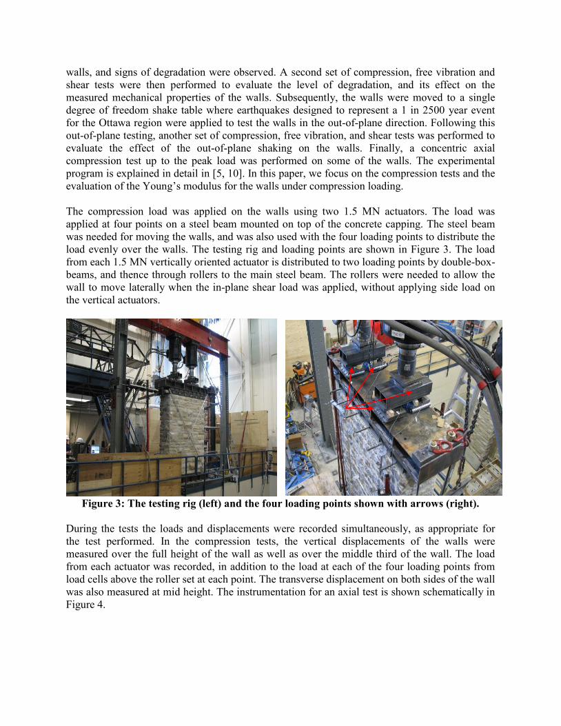
walls, and signs of degradation were observed. A second set of compression, free vibration and shear tests were then performed to evaluate the level of degradation, and its effect on the measured mechanical properties of the walls. Subsequently, the walls were moved to a single degree of freedom shake table where earthquakes designed to represent a 1 in 2500 year event for the Ottawa region were applied to test the walls in the out-of-plane direction. Following this out-of-plane testing, another set of compression, free vibration, and shear tests was performed to evaluate the effect of the out-of-plane shaking on the walls. Finally, a concentric axial compression test up to the peak load was performed on some of the walls. The experimental program is explained in detail in [5, 10]. In this paper, we focus on the compression tests and the evaluation of the Young’s modulus for the walls under compression loading. The compression load was applied on the walls using two 1.5 MN actuators. The load was applied at four points on a steel beam mounted on top of the concrete capping. The steel beam was needed for moving the walls, and was also used with the four loading points to distribute the load evenly over the walls. The testing rig and loading points are shown in Figure 3. The load from each 1.5 MN vertically oriented actuator is distributed to two loading points by double-box-beams, and thence through rollers to the main steel beam. The rollers were needed to allow the wall to move laterally when the in-plane shear load was applied, without applying side load on the vertical actuators.
Figure 3: The testing rig (left) and the four loading points shown with arrows (right).
During the tests the loads and displacements were recorded simultaneously, as appropriate for the test performed. In the compression tests, the vertical displacements of the walls were measured over the full height of the wall as well as over the middle third of the wall. The load from each actuator was recorded, in addition to the load at each of the four loading points from load cells above the roller set at each point. The transverse displacement on both sides of the wall was also measured at mid height. The instrumentation for an axial test is shown schematically in Figure 4.
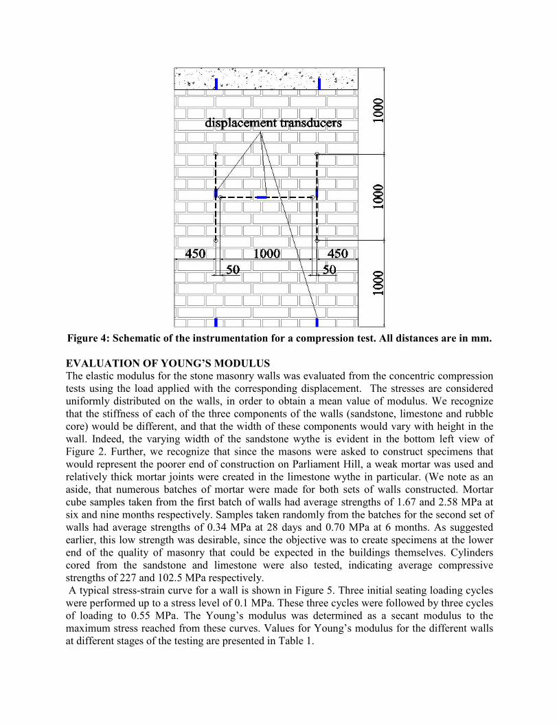
Figure 4: Schematic of the instrumentation for a compression test. All distances are in mm.
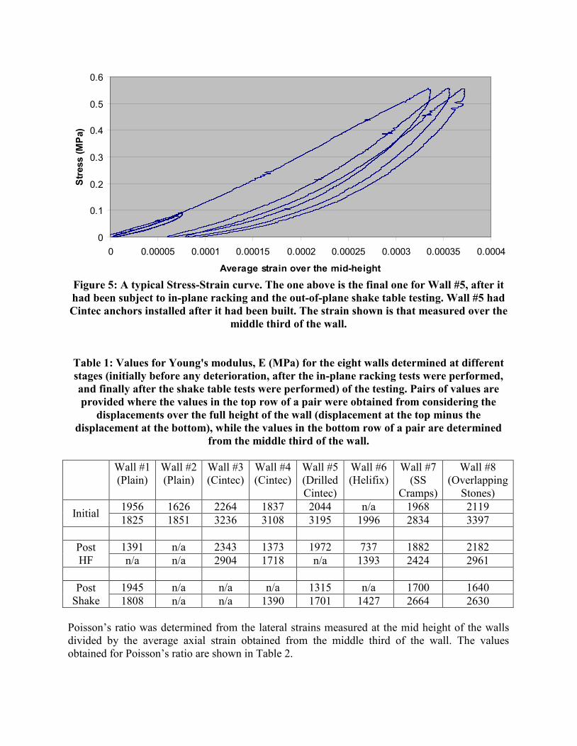
EVALUATION OF YOUNG’S MODULUS The elastic modulus for the stone masonry walls was evaluated from the concentric compression tests using the load applied with the corresponding displacement. The stresses are considered uniformly distributed on the walls, in order to obtain a mean value of modulus. We recognize that the stiffness of each of the three components of the walls (sandstone, limestone and rubble core) would be different, and that the width of these components would vary with height in the wall. Indeed, the varying width of the sandstone wythe is evident in the bottom left view of Figure 2. Further, we recognize that since the masons were asked to construct specimens that would represent the poorer end of construction on Parliament Hill, a weak mortar was used and relatively thick mortar joints were created in the limestone wythe in particular. (We note as an aside, that numerous batches of mortar were made for both sets of walls constructed. Mortar cube samples taken from the first batch of walls had average strengths of 1.67 and 2.58 MPa at six and nine months respectively. Samples taken randomly from the batches for the second set of walls had average strengths of 0.34 MPa at 28 days and 0.70 MPa at 6 months. As suggested earlier, this low strength was desirable, since the objective was to create specimens at the lower end of the quality of masonry that could be expected in the buildings themselves. Cylinders cored from the sandstone and limestone were also tested, indicating average compressive strengths of 227 and 102.5 MPa respectively. A typical stress-strain curve for a wall is shown in Figure 5. Three initial seating loading cycles were performed up to a stress level of 0.1 MPa. These three cycles were followed by three cycles of loading to 0.55 MPa. The Young’s modulus was determined as a secant modulus to the maximum stress reached from these curves. Values for Young’s modulus for the different walls at different stages of the testing are presented in Table 1.
0
0.1
0.2
0.3
0.4
0.5
0.6
0 0.00005 0.0001 0.00015 0.0002 0.00025 0.0003 0.00035 0.0004
Average strain over the mid-height
Stre
ss (M
Pa)
Figure 5: A typical Stress-Strain curve. The one above is the final one for Wall #5, after it had been subject to in-plane racking and the out-of-plane shake table testing. Wall #5 had Cintec anchors installed after it had been built. The strain shown is that measured over the
middle third of the wall.
Table 1: Values for Young's modulus, E (MPa) for the eight walls determined at different stages (initially before any deterioration, after the in-plane racking tests were performed, and finally after the shake table tests were performed) of the testing. Pairs of values are provided where the values in the top row of a pair were obtained from considering the
displacements over the full height of the wall (displacement at the top minus the displacement at the bottom), while the values in the bottom row of a pair are determined
from the middle third of the wall.
Wall #1 (Plain)
Wall #2 (Plain)
Wall #3 (Cintec)
Wall #4 (Cintec)
Wall #5 (Drilled Cintec)
Wall #6 (Helifix)
Wall #7 (SS
Cramps)
Wall #8 (Overlapping
Stones)
Initial 1956 1626 2264 1837 2044 n/a 1968 2119 1825 1851 3236 3108 3195 1996 2834 3397
Post HF
1391 n/a 2343 1373 1972 737 1882 2182 n/a n/a 2904 1718 n/a 1393 2424 2961
Post
Shake 1945 n/a n/a n/a 1315 n/a 1700 1640 1808 n/a n/a 1390 1701 1427 2664 2630
Poisson’s ratio was determined from the lateral strains measured at the mid height of the walls divided by the average axial strain obtained from the middle third of the wall. The values obtained for Poisson’s ratio are shown in Table 2.
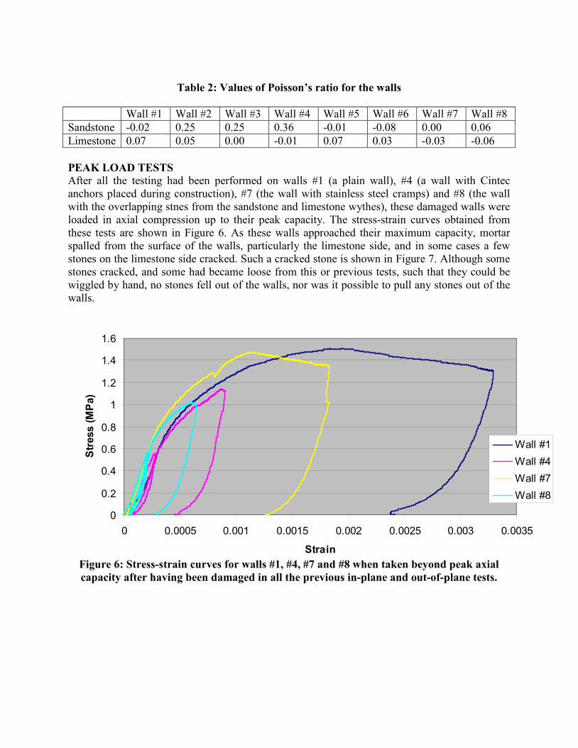
Table 2: Values of Poisson’s ratio for the walls
Wall #1 Wall #2 Wall #3 Wall #4 Wall #5 Wall #6 Wall #7 Wall #8 Sandstone -0.02 0.25 0.25 0.36 -0.01 -0.08 0.00 0.06 Limestone 0.07 0.05 0.00 -0.01 0.07 0.03 -0.03 -0.06 PEAK LOAD TESTS After all the testing had been performed on walls #1 (a plain wall), #4 (a wall with Cintec anchors placed during construction), #7 (the wall with stainless steel cramps) and #8 (the wall with the overlapping stnes from the sandstone and limestone wythes), these damaged walls were loaded in axial compression up to their peak capacity. The stress-strain curves obtained from these tests are shown in Figure 6. As these walls approached their maximum capacity, mortar spalled from the surface of the walls, particularly the limestone side, and in some cases a few stones on the limestone side cracked. Such a cracked stone is shown in Figure 7. Although some stones cracked, and some had became loose from this or previous tests, such that they could be wiggled by hand, no stones fell out of the walls, nor was it possible to pull any stones out of the walls.
0
0.2
0.4
0.6
0.8
1
1.2
1.4
1.6
0 0.0005 0.001 0.0015 0.002 0.0025 0.003 0.0035
Strain
Stre
ss (M
Pa)
Wall #1Wall #4Wall #7Wall #8
Figure 6: Stress-strain curves for walls #1, #4, #7 and #8 when taken beyond peak axial capacity after having been damaged in all the previous in-plane and out-of-plane tests.
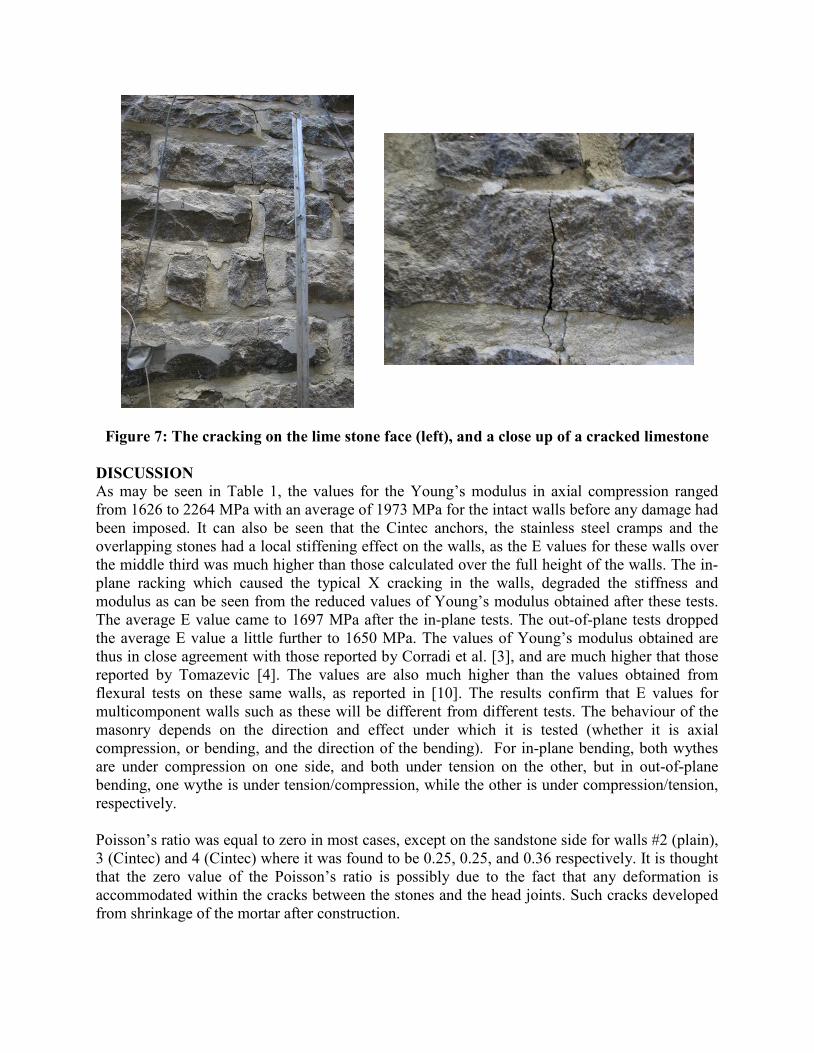
Figure 7: The cracking on the lime stone face (left), and a close up of a cracked limestone
DISCUSSION As may be seen in Table 1, the values for the Young’s modulus in axial compression ranged from 1626 to 2264 MPa with an average of 1973 MPa for the intact walls before any damage had been imposed. It can also be seen that the Cintec anchors, the stainless steel cramps and the overlapping stones had a local stiffening effect on the walls, as the E values for these walls over the middle third was much higher than those calculated over the full height of the walls. The in-plane racking which caused the typical X cracking in the walls, degraded the stiffness and modulus as can be seen from the reduced values of Young’s modulus obtained after these tests. The average E value came to 1697 MPa after the in-plane tests. The out-of-plane tests dropped the average E value a little further to 1650 MPa. The values of Young’s modulus obtained are thus in close agreement with those reported by Corradi et al. [3], and are much higher that those reported by Tomazevic [4]. The values are also much higher than the values obtained from flexural tests on these same walls, as reported in [10]. The results confirm that E values for multicomponent walls such as these will be different from different tests. The behaviour of the masonry depends on the direction and effect under which it is tested (whether it is axial compression, or bending, and the direction of the bending). For in-plane bending, both wythes are under compression on one side, and both under tension on the other, but in out-of-plane bending, one wythe is under tension/compression, while the other is under compression/tension, respectively. Poisson’s ratio was equal to zero in most cases, except on the sandstone side for walls #2 (plain), 3 (Cintec) and 4 (Cintec) where it was found to be 0.25, 0.25, and 0.36 respectively. It is thought that the zero value of the Poisson’s ratio is possibly due to the fact that any deformation is accommodated within the cracks between the stones and the head joints. Such cracks developed from shrinkage of the mortar after construction.
The walls tested up to peak capacity reached stresses ranging between 1 and 1.5 MPa, which is two to three times the estimated stress level at the base of the walls in the buildings on Parliament Hill. The loading was terminated on walls #4 and 8 immediately after reaching the peak strength, while the loading was carried on further for walls # 1 and 7, as some confidence had been gained in the robustness of the construction. Wall #1, a plain wall, reached the code [1] ultimate strain of 0.003. CONCLUSIONS The E values for historic stone masonry walls of the type studied were determined under axial compression. The degradation of the walls caused by the in-plane loading reduced the E values to a greater extent than the out-of-plane loading. Some of the anchor types used appear to cause local stiffening effects in the walls, but not the overall stiffness. When the walls were loaded beyond their peak capacity, some mortar spalled and some limestones cracked, but the walls retained their integrity and no stones fell off the walls. ACKNOWLEDGEMENTS The authors greatly appreciate the support of PWGSC, the ISIS Canada Network of Centres of Excellence, The Department of Civil Engineering and the Faculty workshop, Schulich School of Engineering at the University of Calgary for their help in the execution of this project. REFERENCES
1. National Building Code of Canada 2005 - NRC/IRC 2. Binda, L., and Maierofer, C., “On Site Assessment of Historic Masonry Structures”,
Masonry International, Journal of British Masonry Society, Vol. 20 No 3, 2007 pp 91-105. 3. Corradi, M., Borri, A., Vignoli, A., “Experimental study on the determination of Strength
of Masonry Walls”, Construction and Building Materials, 17 (2003), 325-337. 4. Tomazevic, M., (1999), “Earthquake-Resistant Design of Masonry Buildings”, Imperial
College Press, London. 5. Sorour, M.M., Parsekian, G.A., Duchesne, D., Paquette, J., Mufti, A., Jaeger, L., Shrive,
N.G., (2008) “Experimental Investigation of the Mechanical Properties of Historic Stone Masonry Walls”, Proceedings of the 8th
6. Tomazevic, M., Weiss, P., Velechovsky, T., Apih, V., (1991) “The strengthening of stone masonry walls with grouting”, Structural Repair and Maintenance of Historical Buildings II: Proceedings of the Second International Conference, Seville, Spain, 14-16.
International Seminar on Structural Masonry, Istanbul, Nov, 449-457.
7. Binda, L., Modena, C., Baronio, G., Abbaneo, S., (1997), “Repair and Investigation Techniques for Stone Masonry Wall”, Construction and Building Materials, 11, 3, 133-142.
8. Valluzi, M., Binda, L., Modena, C., (2005), “Mechanical behaviour of historic masonry structures strengthened by bed joints structural repointing”, Construction and Building Materials, 19, 1, 63-73.
9. Maurenbrecher, P., Rousseau, M., (2000), “Repointing Mortars for Older Masonry”, The Canadian Architect, 45, 9, 44.
10. Sorour, M.M., Parsekian, G.A., Duchesne, D. Paquette, J., Mufti, A., Jaeger, L., Shrive, N.G., “Experimental Determination of E and G values for Stone Masonry Walls”, Prohitech 09, June, 2009.