Embed Size (px)
Citation preview

8NCEE Tutorial on FEMA 306/307/308 1
Evaluation, Repair and Enhancement of Earthquake-Damaged Unreinforced Masonry (URM) Buildings
Brian KehoeWiss, Janney, Elstner Associates, Inc.

8NCEE Tutorial on FEMA 306/307/308 2
Test and inspection procedures
Material Structural Or
Material Property Reinf.Conc.
Reinf. Mas.
URM Test ID Test Type
Crack Location and Size
√ √ √ NDE 1 Visual Observation
Spall Location and Size
√ √ √ NDE 1 Visual Observation
√ √ √ NDE 2 Sounding Location of Interior Cracks or Delaminations
√
√
√
NDE 6
Impact Echo
√ NDE 7 SASW √ √ √ IT 1 Selective Removal Reinforcing Bar Buckling or Fracturing
√
√
NDE 1
Visual Observation
√ √ IT 1 Selective Removal
306: 20

8NCEE Tutorial on FEMA 306/307/308 3
Visual Observation

8NCEE Tutorial on FEMA 306/307/308 4
Impact Echo

8NCEE Tutorial on FEMA 306/307/308 5
Test and inspection procedures (continued)
Material
Structural Or Material Property
Reinf.Conc.
Reinf. Mas.
URMTest ID Test Type
Relative Age of Cracks
√ √ √ IT 2 Petrography
Relative Compressive Strength
√ √ √ NDE 3 Rebound Hammer
Compressive Strength
√ √ √ IT 3 Material Extraction and Testing
Reinforcing Bar Location and Size
√ √ NDE 4 Rebar Detector
√ √ NDE 8 Radiography √ √ NDE 9 Penetrating Radar √ √ IT 1 Selective RemovalStrength of Reinforcing Bar
√ √ IT 3 Material Extraction and Testing
306: 20

8NCEE Tutorial on FEMA 306/307/308 6
Ground Penetrating Radar (GPR)

8NCEE Tutorial on FEMA 306/307/308 7
Test and inspection procedures (continued)
Material
Structural Or Material Property
Reinf. Conc.
Reinf. Mas.
URM Test ID Test Type
Wall Thickness √ √ √ NDE 1 Visual Observation √ √ √ NDE 6 Impact Echo √ √ √ IT 1 Selective Removal Presence of Grout in Masonry Cells
√ √ NDE 2 Sounding
√ √ NDE 6 Impact Echo √ √ NDE 7 SASW √ √ IT 1 Selective Removal Strength of Masonry Units
√ √ IT 3 Material Extraction and Testing
√ IT 4, 5 In Situ Testing
Mortar Strength √ √ IT 1 Petrography √ IT 4, 5 In Situ Testing
306: 20

8NCEE Tutorial on FEMA 306/307/308 8
Tests and investigation guides
Example Test and Investigation Guide. See FEMA 306 pgs. 29-59 for other examples:
• Nondestructive tests
• Intrusive tests

8NCEE Tutorial on FEMA 306/307/308 9
Test and inspection proceduresTest Name and ID
For reference and identification
Test Type Nondestructive or Intrusive Materials Applicability to reinforced concrete,
reinforced masonry, or unreinforced masonryDescription Basic overview of the objectives and scope
of the procedure References Applicable standards, detailed specifications,
or sources of additional information Equipment A summary of the tools, instrumentation, or
devices required Execution General sequence of operations Reporting Requirements
Format for reporting of results
Personnel Qualifications
Skill level and specialized training that may be required
Limitations Restrictions on the level of information that can be gained and advice on the interpretation of results

8NCEE Tutorial on FEMA 306/307/308 10
Pre-existing conditions
Recent cracks • Small, loose edge spalls • Light, uniform color of concrete or mortar within crack • Sharp, uneroded edges
Older cracks • Paint or soot inside crack • Water, corrosion, or other stains seeping from crack • Previous, undisturbed patches over crack • Rounded, eroded edges
306: 22

8NCEE Tutorial on FEMA 306/307/308 11
Repair of damage
FEMA 308

8NCEE Tutorial on FEMA 306/307/308 12
Performance restoration• Select restoration measures for damaged component
• Analyze restored structure for performance objective
• Calculate restored Performance Index = dc*/ dd
*
• Adjust scope of restoration measures until dc*/ dd
* is approximately equal to dc / dd
• Cost of final restoration measures quantifies the effects of the damage on seismic performance

8NCEE Tutorial on FEMA 306/307/308 13
Component Damage Classification Guides
• Component type
• Behavior mode
• Evaluation procedures: Analysis, Observation
• Damage severity: Type, Magnitude
• Property modification factors (λ’s): Stiffness, Strength, Displacement acceptability
• Performance restoration measures
See, for example, 306: 95-106

8NCEE Tutorial on FEMA 306/307/308 14
Repair Guides
Repair Category RC RM URM
RepairID Repair Type
• • • CR 1 Surface coating • CR 2 Repointing
Cosmetic Repair
• • CR 3 Crack injection with epoxy• • SR 1 Crack injection with epoxy • • • SR 2 Crack injection with grout • • SR 3 Spall repair • SR 4 Rebar replacement
Structural Repair
• • • SR 5 Wall replacement • • • SE 1 Concrete overlay • • • SE 2 Composite Fibers
Structural Enhancement
• SE 3 Crack Stitching Notes: Repairs for concrete walls can also be used for concrete frames in infill systems. Repairs for steel frames of infill systems are described in the component repair
guides.
308: 22

8NCEE Tutorial on FEMA 306/307/308 15
Repair Guides (continued)
Repair Name and ID
For reference and identification
Repair Category Cosmetic Repair, Structural Repair, or Structural Enhancement
Materials Applicability to reinforced concrete, reinforced masonry, or unreinforced masonry
Description Basic overview of the objectives and scope of the repair procedure
Repair Materials Typical products used for the repair

8NCEE Tutorial on FEMA 306/307/308 16
Repair Guides (continued)
Equipment A summary of the tools, instrumentation, or devices required
Execution General sequence of operations Quality Assurance
Measures required to achieve satisfactory installation
Limitations Restrictions on the effectiveness of the repair
Standards and References
Applicable sources of further information

8NCEE Tutorial on FEMA 306/307/308 17
Direct method• Investigate damage• Identify components• Determine behavior modes• Determine damage severity• Classify component damage• Determine restoration measures for all
components• Estimate costs
306: 75 307: 199

8NCEE Tutorial on FEMA 306/307/308 18
Investigation of damage
Document Damage:•Inspections and Tests•Pre-existing conditions
Assemble Information:•Damaging Earthquake•Building
Classify Component Damage:•Behavior Mode•Severity
VerificationGather more information and revise assumptions to obtain consistency between damage classification and observations
Identify Components:•Materials•Configuration•Behavior
Component DamageRecords
306: 5

8NCEE Tutorial on FEMA 306/307/308 19
Component types and inelastic mechanisms
Pier and Spandrel Mechanisms
RC5
Weak pier, strong spandrelStrong pier, weak spandrel
RC1
Weakly coupled perforated wall
RC1
RC1
RC3
RC2
RC1
RC3
RC3
RC3
RC2
RC4
306: 13

8NCEE Tutorial on FEMA 306/307/308 20
Component Damage Classification Guides
• Component type
• Behavior mode
• Evaluation procedures: Analysis, Observation
• Damage severity: Type, Magnitude
• Property modification factors (λ’s): Stiffness, Strength, Displacement acceptability
• Performance restoration measures
See, for example, 306: 95-106

8NCEE Tutorial on FEMA 306/307/308 21
Component damage recordComplete for each damaged component
Record damage
Note component types
Note behavior modes
Assign severity
Template
Example 306: 33
306: 28

8NCEE Tutorial on FEMA 306/307/308 22
Direct method limitations
• May overestimate effects of damage on performance in future large events
• May underestimate effects of damage on performance in future smaller events
• No useful information on actual building performance
• Cannot be used for design purposes

8NCEE Tutorial on FEMA 306/307/308 23
FEMA 307 Example
Investigation
Evaluation by Direct Method
Evaluation by Relative
Performance Analysis

8NCEE Tutorial on FEMA 306/307/308 24
FEMA 307 Example — Evaluation
Direct Method • Performance restoration measuresRelative Performance Analysis• Performance objectives• Nonlinear static analysis• Pushover capacity curve and
displacement demand• Modifications for damage• Performance restoration measures

8NCEE Tutorial on FEMA 306/307/308 25
FEMA 307 Example — Evaluation
Direct Method • Performance restoration measuresRelative Performance Analysis• Performance objectives• Nonlinear static analysis• Pushover capacity curve and
displacement demand• Modifications for damage• Performance restoration measures

8NCEE Tutorial on FEMA 306/307/308 26
- Prescriptive restoration measures.- Component-by-component.- No assessment of performance.
Direct Method

8NCEE Tutorial on FEMA 306/307/308 27
Component Guides
• By material, component type, & behavior mode
• How to distinguishby observationby analysis
• Damage severitydescriptionmodification factors, λrestoration measures
FEMA Training Seminar Program: Evaluation and Repair of Earthquake Damaged Concrete and Masonry Wall Buildings
306: 96

8NCEE Tutorial on FEMA 306/307/308 28
Performance restoration measures
Direct Method• Cosmetic repairs• Repair coupling beams
Replace heavily damaged coupling beamsInject moderately damaged beams with epoxy

8NCEE Tutorial on FEMA 306/307/308 29
FEMA 307 Example — Evaluation
Direct Method • Performance restoration measuresRelative Performance Analysis• Performance objectives• Nonlinear static analysis• Pushover capacity curve and
displacement demand• Modifications for damage• Performance restoration measures

8NCEE Tutorial on FEMA 306/307/308 30
Seismic Hazard
0
0.2
0.4
0.6
0.8
1
1.2
0 0.5 1 1.5 2 2.5 3 3.5
Life Safety - 10%/50 yr
Immediate Occupancy -50%/50 yr
SA(g)
T(s)
306: 96

8NCEE Tutorial on FEMA 306/307/308 31
Investigation of damage
Document Damage:•Inspections and Tests (3.3, 3.8)•Pre-existing conditions (3.4)
Assemble Information:•Damaging Earthquake (3.1)•Building (3.2)
Classify Component Damage:(3.5)•Behavior Mode (5,6,7,8)•Severity (5,6,7,8)
Verification (3.6)
Gather more information and revise assumptions to obtain consistency between damage classification and observations
Identify Components: (2.4,5,6,7,8)•Materials•Configuration•Behavior
Component DamageRecords (3.7)
306: 5

8NCEE Tutorial on FEMA 306/307/308 32
Damaging earthquake - ground motion
Example plot: spectral acceleration contours; building sites
306: 21

8NCEE Tutorial on FEMA 306/307/308 33
Damaging earthquake - site spectrum
Period, T(sec.)
Spectral Acceleration, Sa
0.5 1.0 1.5
Sa at T=0.3sec from Figure 3-3
Sa at T=1.0 sec from Figure 3-4
PGA atT=0 sec from Figure 3-2
Sa = (Sa at T=1.0)/ T
306: 18

8NCEE Tutorial on FEMA 306/307/308 34
Bearing wall buildings
Section
Elevation
Floor and roof loadssupported on wall
Concrete or masonrybearing wall
Portion of vertical load may becarried by beam/slab/columnframing
306: 11
8NCEE Tutorial on FEMA 306/307/308 35
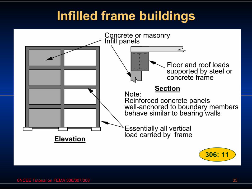
Infilled frame buildings
Section
Elevation
Floor and roof loadssupported by steel orconcrete frame
Concrete or masonryInfill panels
Essentially all verticalload carried by frame
Note:Reinforced concrete panelswell-anchored to boundary membersbehave similar to bearing walls
306: 11

8NCEE Tutorial on FEMA 306/307/308 36
Elements and Components
A2
A3A1 A5
A4
Global Structure Wall Element A
Components
Returns included in propertiesof components A1 and A5
Wall element A Wall element B
306: 9

8NCEE Tutorial on FEMA 306/307/308 37
Component types for RC wallsComponent Type Description
RC1: Cantilever Wall or Stronger Wall Pier
Stronger than beam or spandrel elements that may frame into it so that nonlinear behavior (and damage) is generally concentrated at the base, with a flexural plastic hinge or shearfailure. Includes isolated (cantilever) walls. If the componenthas a major setback or cutoff of reinforcement above the base, this section should be also checked for nonlinear behavior.
RC2: Weaker Wall Pier
Weaker than the spandrels to which it connects, characterized by flexural hinging top and bottom, or shear failure
RC3: Weaker Spandrel or Coupling Beam
Weaker than the wall piers to which it connects, characterized by hinging at each end, shear failure, sliding shear failure
RC4: Stronger Spandrel
Should not suffer damage because it is stronger than attached piers. If this component is damaged, it should probably be re-classified as RC3
RC5: Pier-Spandrel Panel Zone 306: 78

8NCEE Tutorial on FEMA 306/307/308 38
FEMA 307 Example — Evaluation
Direct Method • Performance restoration measuresRelative Performance Analysis• Performance objectives• Nonlinear static analysis• Pushover capacity curve and
displacement demand• Modifications for damage• Performance restoration measures

8NCEE Tutorial on FEMA 306/307/308 39
Relative Performance Analysis is Based on the Nonlinear Static Procedure, NSP.
(Push-Over Analysis)
V
∆
∆
V

8NCEE Tutorial on FEMA 306/307/308 40
3D Computer Analysis Model
Coupled Wall
Beam Elements Representing Solid Wall
Beam Elements Representing Floor Slab
Nodes Where Lateral Loads are Applied 307: 205

8NCEE Tutorial on FEMA 306/307/308 41
Coupled Wall – Frame Model
R ig id E n dO f f s e t
N o d e
C o lu m n E le m e n t
C o u p l in g B e a mE le m e n t
C o lu m n E le m e n tR e p r e s e n t in g W a l l P ie r
307: 204
Rigid end offsets model the joint legions

8NCEE Tutorial on FEMA 306/307/308 42
Coupled Wall – Shell Model
Column18 inch
Column18 inch
Wall12 inch Coupling
Beam

8NCEE Tutorial on FEMA 306/307/308 43
FEMA 356 Component ModelingShear Walls — Initial Stiffness
• Flexural (Uncracked): 0.8 Ec Ig• Flexural (Cracked): 0.5 Ec Ig• Shear: 0.4 Ec Aw
Coupling Beams — Initial Stiffness• Flexural: 0.5 Ec Ig• Shear: 0.4 Ec Aw

8NCEE Tutorial on FEMA 306/307/308 44
SAP 2000 Element Modifications

8NCEE Tutorial on FEMA 306/307/308 45
FEMA 307 Example — Evaluation
Direct Method • Performance restoration measuresRelative Performance Analysis• Performance objectives• Nonlinear static analysis• Pushover capacity curve and
displacement demand• Modifications for damage• Performance restoration measures

8NCEE Tutorial on FEMA 306/307/308 46
FEMA 356 Component Properties
Shear Wall Coupling Beams
050
100150200250300
0 0.005 0.01
Rotation
Forc
e
IO LSp CPp
LSs CPs
IO: Immediate Occupancy
LS: Life SafetyCP: Collapse
Preventionp: primarys: secondary

8NCEE Tutorial on FEMA 306/307/308 47
Pre-event pushover curve
0
2,000
4,000
6,000
8,000
10,000
0 0.5 1 1.5 2
Roof Displacement (Inches)
Ba
se
Sh
ea
r (k
ips
) Pushover curve
Bilinear idealizedcurve

8NCEE Tutorial on FEMA 306/307/308 48
Displacement Demand
By the FEMA 356 Nonlinear static procedure, calculate displacement demand using the coefficient method.
24πe
t 0 1 2 3 aTC C C C Sδ =Coefficient method:
356: 3-21

8NCEE Tutorial on FEMA 306/307/308 49
Seismic Hazard
0
0.2
0.4
0.6
0.8
1
1.2
0 0.5 1 1.5 2 2.5 3 3.5
Life Safety - 10%/50 yr
Immediate Occupancy -50%/50 yr
SA(g)
T(s)
306: 96

8NCEE Tutorial on FEMA 306/307/308 50
Pre-event pushover curve
0
2,000
4,000
6,000
8,000
10,000
0 0.5 1 1.5 2
Roof Displacement (inches)
Ba
se
Sh
ea
r (k
ips
) Pushover curve
Bilinear idealizedcurve
dd life safety

8NCEE Tutorial on FEMA 306/307/308 51
Damaging Earthquake
0.0
0.2
0.4
0.6
0.8
1.0
1.2
0 0.5 1 1.5 2 2.5 3Period (Sec.)
Spe
ctra
l Acc
eler
atio
n (g
)
5% Damp10% Damp20% Damp
Spec
tral
Acc
eler
atio
n (g
)

8NCEE Tutorial on FEMA 306/307/308 52
Pre-event pushover curve
0
2,000
4,000
6,000
8,000
10,000
0 0.5 1 1.5 2
Roof Displacement (inches)
Ba
se
Sh
ea
r (k
ips
)
Pushover curve
Bilinear idealizedcurvede

8NCEE Tutorial on FEMA 306/307/308 53FEMA Training Seminar Program: Evaluation and Repair of Earthquake Damaged Concrete and Masonry Wall Buildings
Time
Pre-eventState
OriginalPerformanceDamage State
PerformanceEarthquake dd
a) Building without prior earthquake damage
IntermediateDamage State
DamagingEarthquake
PerformanceDamage State ( ' )
dd'de
b) Building with prior earthquake damage
306: 3
308: 11

8NCEE Tutorial on FEMA 306/307/308 54
FEMA 307 Example — Evaluation
Direct Method • Performance restoration measuresRelative Performance Analysis• Performance objectives• Nonlinear static analysis• Pushover capacity curve and
displacement demand• Modifications for damage• Performance restoration measures

8NCEE Tutorial on FEMA 306/307/308 55FEMA Training Seminar Program: Evaluation and Repair of Earthquake Damaged Concrete and Masonry Wall Buildings
306: 66

8NCEE Tutorial on FEMA 306/307/308 56FEMA Training Seminar Program: Evaluation and Repair of Earthquake Damaged Concrete and Masonry Wall Buildings
LS = Life Safety
CP = CollapsePrevention
A
B C
D E E'D'
C'B'
A'
RD
IO = Immediate Occupancy
Undamaged Component Damaged Component
IO' = IO - RDLS' = λD
LS - RD
CP'= λDCP - RD
designates primary components designates secondary components
b) Component deformation limits
P S
S
S
S
P P
P P P
S 306: 67
8NCEE Tutorial on FEMA 306/307/308 57
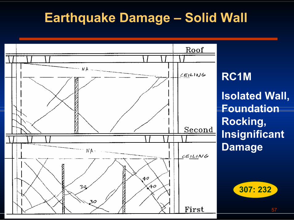
Earthquake Damage – Solid Wall
RC1M
Isolated Wall, Foundation Rocking, Insignificant Damage
307: 232

8NCEE Tutorial on FEMA 306/307/308 58
Earthquake Damage – Coupled Wall
307: 223

8NCEE Tutorial on FEMA 306/307/308 59
Component Classifications
RC1N RC1N
RC3H
RC3H
Damage Severity
ModerateHeavyInsignificant

8NCEE Tutorial on FEMA 306/307/308 60
Post-Earthquake Modifications
Element BehaviorMode
Severity ModificationFactors
Pier PierRocking
Insignificant λk=1.0λQ=1.0λD=1.0
CouplingBeam
PreemptiveDiagonalShear
Moderate λk=0.5λQ=0.8λD=0.9
CouplingBeam
PreemptiveDiagonalShear
Heavy λk=0.2λQ=0.3λD=0.7

8NCEE Tutorial on FEMA 306/307/308 61
Damaged Component Properties
0
50
100
150
200
250
0 0.002 0.004 0.006 0.008 0.01 0.012
Rotation (radians)
Shea
r (k
ips) Heavy Damage
Moderate Damage

8NCEE Tutorial on FEMA 306/307/308 62
Comparison of Pre-Event and Post-Event Performance
0
1,000
2,0003,000
4,000
5,000
6,0007,000
8,000
9,000
0 0.5 1 1.5 2
Roof Displacment (Inches)
Bas
e Sh
ear (
kips
)
Pre-eventPost-event

8NCEE Tutorial on FEMA 306/307/308 63
Performance Comparison
• Capacity versus Demand (C/D)Capacity based on displacement limits for critical componentDemand based on target displacement using design earthquake
• Compare pre-event capacity to demand• Compare post-event capacity to demand• Difference in C/D ratio is an indication of
amount of loss of performance

8NCEE Tutorial on FEMA 306/307/308 64
Comparison of Pre-Event and Post-Event Performance
dd and dd’dc’
dc
0
1,000
2,0003,000
4,000
5,000
6,0007,000
8,000
9,000
0 0.5 1 1.5 2Roof Displacment (inches)
Base
She
ar (k
ips)
Pre-eventPost-event
8NCEE Tutorial on FEMA 306/307/308 65
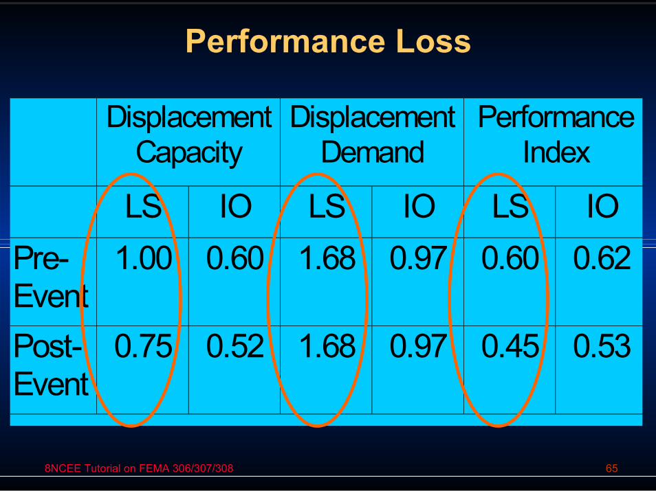
Performance Loss
Displacement Capacity
Displacement Demand
Performance Index
LS IO LS IO LS IO Pre-Event
1.00 0.60 1.68 0.97 0.60 0.62
Post-Event
0.75 0.52 1.68 0.97 0.45 0.53

8NCEE Tutorial on FEMA 306/307/308 66
FEMA 307 Example — Evaluation
Direct Method • Performance restoration measuresRelative Performance Analysis• Performance objectives• Nonlinear static analysis• Pushover capacity curve and displacement
demand• Modifications for damage• Performance restoration measures

8NCEE Tutorial on FEMA 306/307/308 67
FEMA 307 Example — Evaluation
Direct Method:- Prescriptive restoration measures.- Component-by-component.- No assessment of performance.
Relative Performance Analysis:- Devise measures to restore performance
ability (Displacement Demand/Capacity) for performance levels of interest

8NCEE Tutorial on FEMA 306/307/308 68
Performance restoration measures
Relative Performance Analysis• Nonstructural repairs• Various alternatives could be tried
to restore structural performance. Choose repair of coupling beams.
Replace heavily damaged coupling beamsInject moderately damaged beams with epoxy

8NCEE Tutorial on FEMA 306/307/308 69
Performance restoration measures
0
50
100
150
200
250
300
0.000 0.005 0.010 0.015 0.020 0.025 0.030 0.035
Rotation, Radians
She
ar, K
ips
0
50
100
150
200
250
300
0.000 0.005 0.010 0.015 0.020 0.025 0.030 0.035
Rotation, Radians
She
ar, K
ips
Moderate
Heavy
Force-displacement for coupling beams:
a) Pre-event
b) Post-event
307: 207

8NCEE Tutorial on FEMA 306/307/308 70
Performance restoration measures
0
50
100
150
200
250
300
0.000 0.005 0.010 0.015 0.020 0.025 0.030 0.035
Rotation, RadiansS
hear
, Kip
s
Moderate
Heavy
0
50
100
150
200
250
300
0.000 0.005 0.010 0.015 0.020 0.025 0.030 0.035
Rotation, Radians
She
ar, K
ips
Force-displacement for coupling beams:
b) Post-event
c) Replacement Coupling Beam with Diagonal Reinforcement
307: 207

8NCEE Tutorial on FEMA 306/307/308 71
FEMA 307 Example — EvaluationDirect Method • Performance restoration
measuresRelative Performance Analysis• Performance objectives• Nonlinear static analysis• Pushover capacity curve and
displacement demand• Modifications for damage• Performance restoration
measures

8NCEE Tutorial on FEMA 306/307/308 72
Questions