Embed Size (px)
Citation preview
l8 R&D JOURNAL APRIL 1987
A Procedure for the Design or Rating of GounterflowEvaporative Cooler Cores
P. J. Erens*U n iver sity of SlellenDosch
A computerised method for determining the size of evaporative cooler cores based on the method ofMizushina is described. An additional program using the above procedure can be used to rate the perfor-mance capabilities of a given coil with specified inlet conditions. Block diagrams for both procedures aregiven and problems encountered in using the method are discussed. Some exarnple calculations are alsogiven. Although the principles of the method have previously been desuibed in the literature the author hasattempted to point out some of the problems and pitfalls experienced in developing a successful algorithmfor the design or rating of evaporative coolers.
Nomenclature Units
[m'lmt]
[mtlmt]
area per unit volume of coil outsidetubes
a' area per unit volume of coil air-water interface
A area inside tubesA' area at air-water interfaceB coil breadthC specific heatD tube diameter 6
f fouling factori enthalpyK mass transfer coefficientL length of coilm flowrateNH number of rows, horizontallyNV number of rows, verticallyp pitchq heat transfer rateR Reynolds numberT temperatureU0 overall heat transfer coemcientv specific volumeV velocityZ coil heightd. heat transfer coefficient
It vlscoslty
Subscripts
air-water vapour mixtureinlet air (at bottom of tower)saturation value corresponding to process fluid outlettemperature
arwo saturation value corresponding to recirculating wateroutlet temperature
ao outlet airaos outlet air, saturated conditionH horizontalV verticalp preferredpf process fluidpfi process fluid inlet condition (top of coil)pfo process fluid outlet conditionrw recirculating waterrwi recirculating water inlet conditionrwo recirculating water outlet conditionwbi wet bulb at air inlet
*Professor
Department of Mechanical EngineeringUniversity of Stellenbosch
Introduction
The design of conventional evaporative cooling tower cores is atthis stage fairly well documented and although sophisticatedcomputer design techniques do exist, the methods used can beconsidered as text-book material. However, this is not yet thecase for evaporative coolers and condensers, the reason beingthat it is difficult to produce an accurate closed form designsolution for these devices.
For brevity evaporative coolers or condensers are seen asmulti-tube heat exchangers with or without fins situated inside awet cooling tower and serving the dual purpose of heat ex-changer and fill-material.
There is a considerable lack of design information on thistype of apparatus due to its relative complexity compared to theconventional heat exchanger or cooling tower. It is in fact a
three-fluid heat transfer device utilising both heat and masstransfer mechanisms. Because of its complexity closed formsolutions to determine outlet conditions or sizes are not pos-sible. It is therefore essential to resort to rather complicatedcomputer solutions, even when using approximations such asMerkel's theory on the air side.
Some of the methods found in the literature are discussed anda procedure to determine either core sizes or outlet conditions isdescribed with particular reference to the problems experiencedin finding a solution. Some practical examples are also given.
Although the method is restricted to counterflow coolers itcould easily be extended to accommodate crossflow exchangers.Little effort would be required to modify the program to accom-modate evaporative condensers.
Available design information
The design of an evaporative cooler/condenser incorporates theuse of conventional heat transfer theory on the process fluid orrefrigerant side, up to the air-water interface, where separateheat and mass transfer equations or the Merkel equation areapplied.
The most applicable design methods for conventional tube orfinned tube exchangers are those described by Leidenfrost andKorenic |,2f, Mizushina et al [3] and Webb [4]. The formerauthors used a more rigorous approach, keeping the heat andmass transfer equations separate in their analysis. However, theassumption of a Lewis number of unity was employed. In con-trast Mizushina employed the Merkel (see for example Stoeckerand Jones tl3l) approximation on the air side. The methods ofboth groups require the simultaneous numerical integration ofenergy equations for the air, process fluid and recirculatingwater to obtain a solution. In doing so the relevant heat or masstransfer equations are also employed.
Kreid et al [5], have proposed an approximate method where-by the heat and mass transfer equations are manipulated toproduce an overall heat transfer equation related to enthalpy
mr]m'lmlJ/kg Klmlm2 "C/WlUkelke/s per J/kglml
lke/sI
lmltwl
['c][W/m2'C]lm'/kellm/sl[-][W/m"C][kg/ms]
aarapfo
N&O JOERNAAL APRIL 1987
difference. While this method is possibly useful for a first orderapproximation it contains some drastic assumptions and istherefore not recommended for design purposes. A similar ap-proach has also been suggested by Perez-Blanco and Linkoust6t.
In this article a method similar to that of Mizushina et al [3] isdescribed with a considerable relaxation of the conditions pro-posed by them. While it is perhaps less accurate than the methodof Leidenfrost and Korenic [, 2), it should be borne in mindthat an integral number of pipe rows must usually be deter-mined and the answers are unlikely to differ. However, whendetermining the capability of a given cooler of fixed dimensionsit is very likely that Leidenfrost's method will produce a moreaccurate solution.
Theoretical background
While the previous authors have adequately described thetheory behind evaporative condensers or coolers, a shortresum6 is given for clarity.
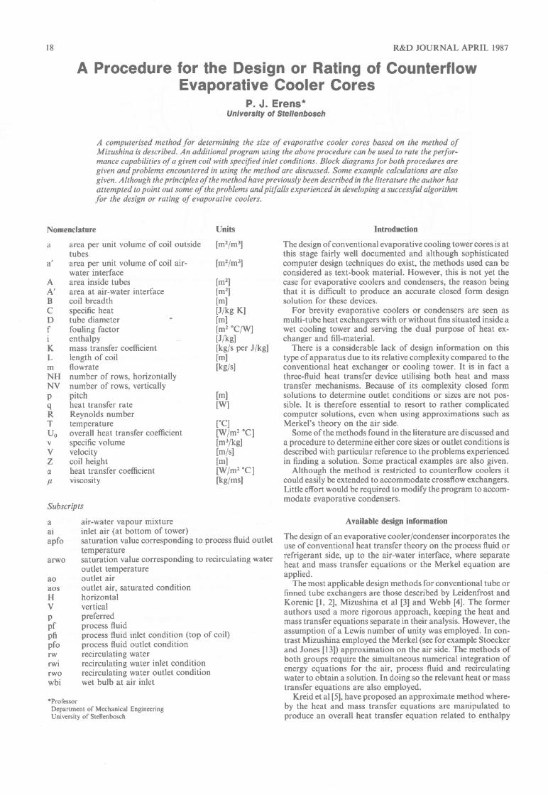
In order to analyse such a cooler, energy equations must beset up for all three fluids, together with the relevant heat or masstransfer equations. In this case a counterflow tower with airflowing upwards and both process fluid and recirculating waterflowing downwards is considered (see Figure l). As this proce-dure concerns the core design, it is irrelevant whether the toweris of the forced or induced draught type, although these optionsmay well have definite practical implications. Themethod can be applied to either bare tube or finned tube cores.
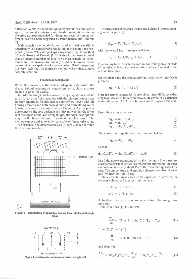
A horizontal one-dimensional slice (Figure 2) taken throughthe tower is considered.
Figuur 1 - Gounterflow eyaporative cooling tower (induced draughttvpe)
RECIRCULATING UATER
Figure 2 - Schematic incremental slice through coil
l9
The heat transfer between the process fluid and the recirculat-ing water is given by
deo, : U".(Tor - T,*). dA
with the overall heat transfer coefficient
uo -- I/(D"/Dr.dpr + |la*, + f) (2)
f is a fouling factor which can account for fouling on either sideof the tube while d.* is a heat transfer coefficient related to the
outside tube area.
On the other hand the heat transfer at the air-water interface isgiven by:
Here the elemental area dA' is used since it may differ consider-ably from dA when fins are employed. However, in a particularcooler the ratio dA/dA' will be constant throughout the coil.
From the energy equation:
dqo, : tror.Cor.dTordq" _ rh"'di"dgr* : fr*.C*. dTr*
The above three equations are in turn coupled by:
dgor:dq*,+dq,
so that
fror.Cor.dTpr : fr.*.C*.dTr* + rh". dioPROCESS FLUID
In all the above equations, (a) to (8), the mass flow rates areconsidered constant, which is a reasonable approximation sinceevaporation is usually abofi lo/o of the recirculating water flowrate. The temperature and enthalpy changes are also taken aspositive from bottom to top.
The elemental areas can also be expressed in terms of theelement volume and area per unit volume.
(l)
(3)
(4)(5)(6)
(7)
(8)
dA _ L. B. a.dz
dA' - L. B. a' .dz
A further three equationspurposes.From equations (l), (4) and
(e)
(10)
are now derived for integration
(e)
qe - (U".a. B. Lirhpr.Co,).(Tor T.*)
dz
from (3), (5) and ( l0)
and from (8)
+ _ (fror.cor/rh*.c*) + (rir,/rir'*.c*) +oz oz dz
(l l)
ARdi"
dz(12)
(13)
PROCESS FLUID
^rR / ^rR \
20
Design procedure
Prac tical C onsiderat ions
In establishing a leasible design approach certain practicalaspects of the cooler must be considered. They are, amongstothers, acceptable process fluid flow rates, recirculating waterflow rates, tube sizes and air velocities. While Mizushina's [3]program allows for a number of tube sizes, it is restricted totriangular arrangements with a pitch of two diameters. In thisprogram the tube size is chosen depending on availability ofmaterial.
Their recommended interior and exterior flow rates are alsoacceptable, but may be deviated from depending on the shape ofcooler required (e.g. square or oblong). Such deviations affectthe process fluid or recirculating water Reynolds numbers, andtherefore the heat transfer coefficients, slightly. Inadequatevelocities inside the tubes may cause fouling problems, in whichcase smaller diameter tubes can be selected.
A recirculating water flow rate of 150 to 200 kg/hr per meterof tube is usually sufficient to give adequate heat transfer coeffi-cients without an excessive rate of evaporation in comparison tothis rate. Excessive flow rates should be avoided as the recircu-lating water tends to inhibit airflow, increasing the required fanpower.
While it is possible, using various restricting equations pro-posed by Mizushina [3], to calculate the air mass flow rate, themaximum practical air velocity mirst be taken into account.This is usually in the order of 2,5 to 3 m/s in most towers and isdetermined by the rate of droplet entrainment. In this programthe air velocity is chosen by the user and a value of 2,5 m/s isrecommended.
Procedure to design a core for given process requirements.
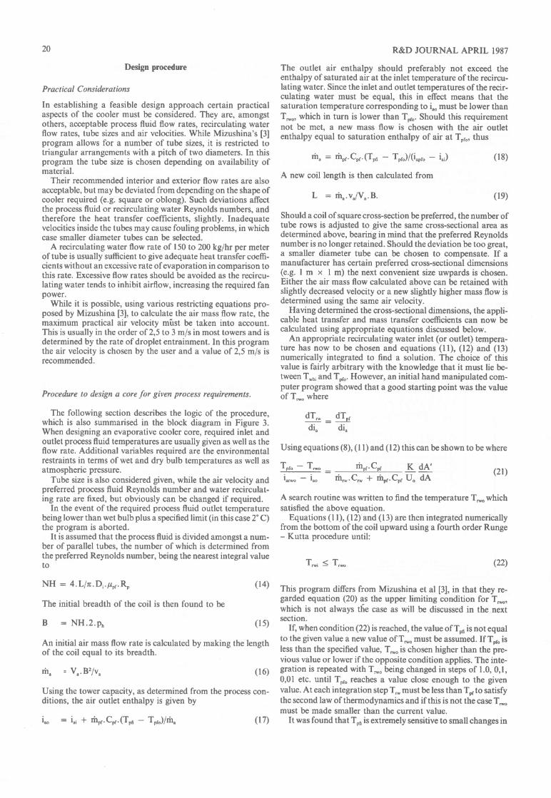
The following section describes the logic of the procedure,which is also summarised in the block diagram in Figure 3.When designing an evaporative cooler core, required inlet andoutlet process fluid temperatures are usually given as well as theflow rate. Additional variables required are the environmentalrestraints in terms of wet and dry bulb temperatures as well asatmospheric pressure.
Tube size is also considered given, while the air velocity andpreferred process fluid Reynolds number and water recirculat-ing rate are fixed, but obviously can be changed if required.
In the event of the required process fluid outlet temperaturebeing lower than wet bulb plus a specified limit (in this case 2" C)the program is aborted.
It is assumed that the process fluid is divided amongst a num-ber of parallel tubes, the number of which is determined fromthe preferred Reynolds number, being the nearest integral valueto
NH : 4.Lln.Di.lpr.Ro
The initial breadth of the coil is then found to be
B - NH .2.pn
R&D JOURNAL APRIL 1987
The outlet air enthalpy should preferably not exceed theenthalpy of saturated air at the inlet temperature of the recircu-lating water. Since the inlet and outlet temperatures of the recir-culatirrg water must be equal, this in effect means that thesaturation temperature corresponding to i"o must be lower thanT*o, which in turn is lower than Tpro. Should this requirementnot be met, a new mass flow is chosen with the air outletenthalpy equal to saturation enthalpy of air at Tpro, thus
rhu - fror.Cor.(Too To")/(i"'" i",)
A new coil length is then calculated from
(l 8)
(le)
(2t)
L - rh". v"/V". B.
Should a coil of square cross-section be preferred, the number oftube rows is adjusted to give the same cross-sectional area asdetermined above, bearing in mind that the preferred Reynoldsnumber is no longer retained. Should the deviation be too great,a smaller diameter tube can be chosen to compensate. If amanufacturer has certain preferred cross-sectional dimensions(e.g. I m x I m) the next convenient size uwpards is chosen.Either the air mass flow calculated above can be retained withslightly decreased velocity or a new slightly higher mass flow isdetermined using the same air velocity.
Havirrg determined the cross-sectional dimensions, the appli-cable heat transfer and mass transfer coefficients can now becalculated using appropriate equations discussed below.
An appropriate recirculating water inlet (or outlet) tempera-ture has now to be chosen and equations (ll), (12) and (13)numerically integrated to find a solution. The choice of thisvalue is fairly arbitrary with the knowledge that it must lie be-tween T*' and Tpro. However, an initial hand manipulated com-puter program showed that a good starting point was the valueof T.*o where
dT* : g&di" di"
Using equations (8), (l l) and (12) this can be shown to be where
Toro - Tr*o -
rhos.Cor K dA'i"r,,o iuo tr*.Cr* + fror.Cos fJo dA
A search routine was written to find the temperature T.*o whichsatisfied the above equation.
Equations (l l), (12) and (13) are then integrated numericallyfrom the bottom of the coil upward using a fourth order Runge- Kutta procedure until:
Tr*i (22)
(14) This program differs from Mizushina et al [3], in that they re-garded equation (20) as the upper limiting condition for T*o,which is not always t6e case as will be discussed in the nextsectron.
If, when condition (22) is reached, the value of Tpn is not equal(ls)
An initial air mass flow rate is calculated by making the length :: th^: 9i":t *lue a new value of r*-must be assumed' If ror. is
of the coil equal to its breadth. ---- ----o---
less than the specified value, T*o is chosen higher than the pre-vious value or lower if the opposite condition applies. The inte-
rh" = V".B2/v" (16) gration is repeated with T*o being changed in steps of 1"0, 0,1,0,01 etc. until Toro reaches a value close enough to the given
Using the tower capacity, as determined from the process con- value. At each integration step T* must be less than To, to satisfyditions, the air outlet enthalpy is given by thesecondlawof thermodynamicsandifthisisnotthecaseT
must be made smaller than the current value.i"o - i"i + frpr.Cor.(Too Tor,)/rh" (17) It was found that Too is extremely sensitive to small changes in
N&O JOERNAAL APRIL 1987 2l
llPt TsI I hocrss Fluld ln-ond
oul le I lorqcrclurosll I I Alr rri ond drybulb
I rrprr ol ur e sll I I I Boronrlrlc pr.ssurI lvl Tube dlonrlrrlv I Air ve loc I lylvl I Rcclrculollng rolrr
rotc prr mrlcr plpflvl I I Prrlerrcd proc.ss
f luld Roynolds l,lo.lvllll Vrrllcol ond
horlzonlol pltch
/ ls\out lel Tposslblr
Colculolo no. ofhor lzonlol rors
Enecdlh = i*|.2nt;;;ri' = e;;dit
[hlcrnlnr inltlolnoss I I or
Colculole oullrlolr rnlholpy
oo t loo. )gr Tpr
Co lcu lotr rir rl lhior : loo, ol Tptc
Colculolr col I
I rnglh
Adluel dlnrnslonsfor drs I rrdshcpr a .9. squora
Colculolr hcolond noss lronglrr
coefl I c lrnlg
h lnt Toro lsloo I br
Choose lnltlolTrro so thol
#= ff " boron
lnlcArolr lronbollon up uslngRungr - Kullo mrlhodunlll Trrt , Trro
Choose higher Choosr I orer
1 c TpllsPcclflrd
Colculolr nun5er olvrr I I co I rors cnd ho I ghle
fu lnlCol I 0lnrnslons
Flgure 3 - Block dlagram for program to determlne evaporatlve cooler coll slze
22 R&D JOURNAL APRIL 1987
I NPUTS
lil Coll Breodlhllil Coil Lenglhliill Almospheric
condillonslivl Pipe size 6 pilch(vl No. off horizonlol
ond verllcol rouslvil Air f low rolelvlil Recirculoling
woler rolelvilll Proccss f luld
rols ond inlellemperolure
Colculole minimump.f. outlel lemp.
Choose Toto greolerthon obove volue
Colculole or€os qndheol ond moss
lronsfir cocfficienls
Choose Trro so thotdT.r=d'IP|'ot
boilom0to 0to
Choose h igherT pto
lnlegrole frombol lom up us i ngRunge Kut lo me lhod
Choose I owerT pto
Choose I owerChoose h igherT pto
rI t Tof tlsPecif ied
ri Tpl lsPecif iedl
Co I cu I ole number ofverlicol rows NV
glvrn NV:NVglvr4
Yes
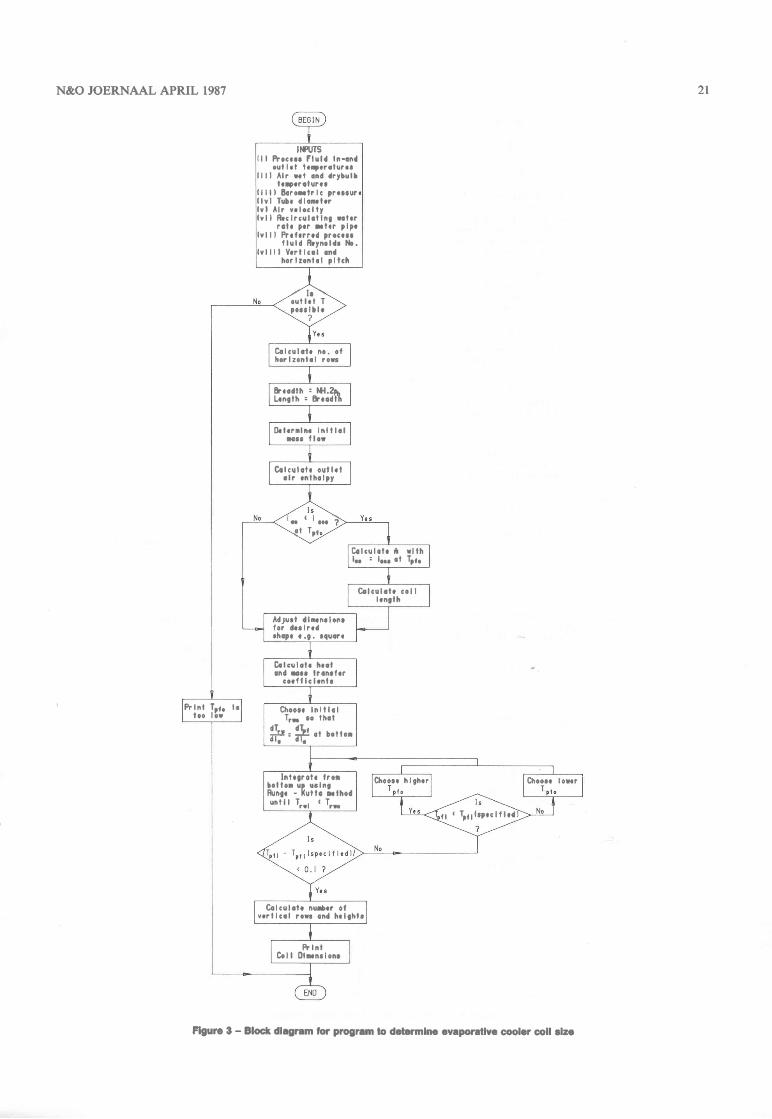
Figure 4 - Block diagram lor coil rating program
N&O JOERNAAL APRIL 1987
20
T*o and it is essential to use double precision throughout theprogram.
Having determined the value of T,*o which satisfies the pro-cess conditions the number of integration steps can be countedto determine the coil height, z. From this the number of verticalrows can be determined being the integer value higher than
NZ - zlp"
Procedure to evaluate an existing cooler
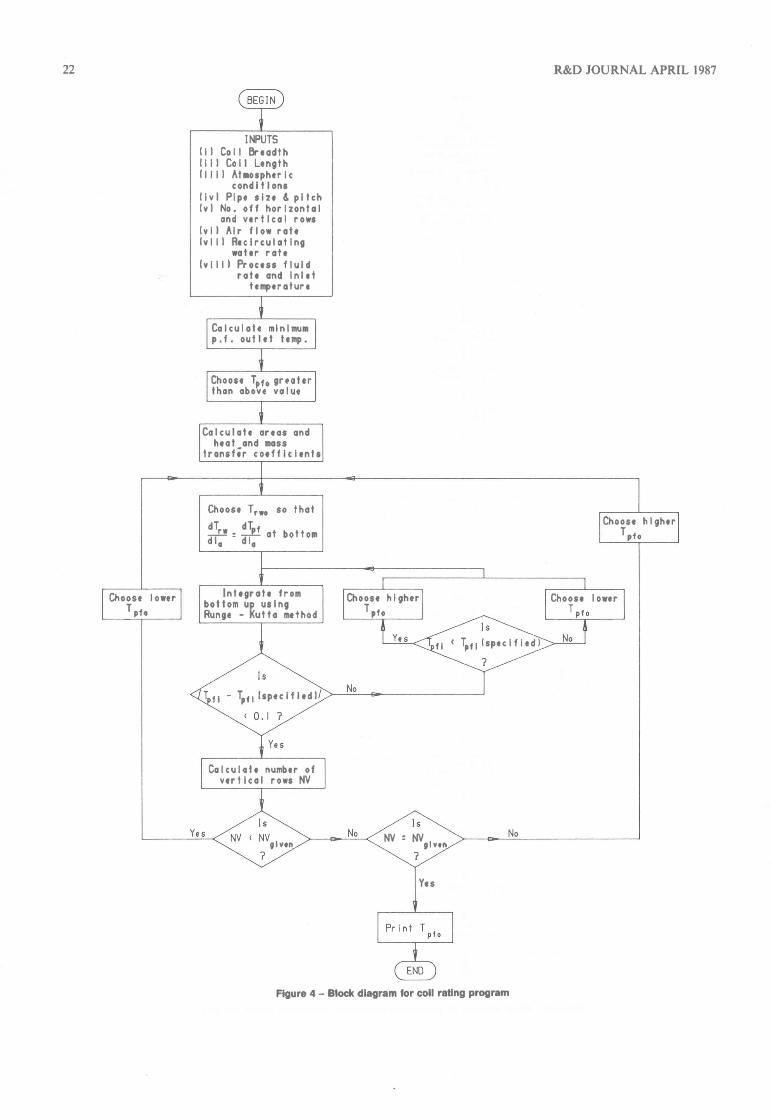
The procedure described above has been used successfully todesign an evaporative cooler core. However, a more frequentrequirement is to determine the performance capability of anexisting cooler with given air and process fluid inlet conditions.This is especially the case where a company has a series of coolermodels where dimensions cannot easily be changed. Operationat other altitudes and environmental conditions is also obvious-ly of interest.
In this case parts of the above program can be used with somechanges to the sequence of calculations. Obviously the dimen-sions are fixed and the heat and mass transfer equations arecalculated using the specified flow rates. The procedure
50
described above to find the coil height is then used iterativelyuntil an exchanger having the same number of vertical rows isfound. The program logic is summarised in the block diagramshown in Figure 4.
First, a minimum possible process fluid outlet temperature isdetermined from an energy balance using the given air and pro-cess fluid inlet conditions and flow rates. This usually occurswhen the outlet air is saturated at the process fluid outlet tem-perature. It is then necessary to determine a value of Ton" corre-sponding to ioo, using the energy balance. This value would cor-respond to the condition of maximum (100%) effectiveness. Aninitial effectiveness of 80% is then arbitrarily chosen and thenumber of vertical rows determined for the corresponding valueof Tor,. If the number of rows is greater than the specified num-ber a lower effectiveness is chosen and vice versa until the calcu-lated number of rows equals the actual number.
Comment on Heat and Mass Transfer Equations and FinEfficiencies
Heat transfer equations
The heat transfer equations for the process fluid inside the tubes
23
r6
r5
l4
t3
t2
il
r0
oz-o(rb-c)o-oF
2
30 40
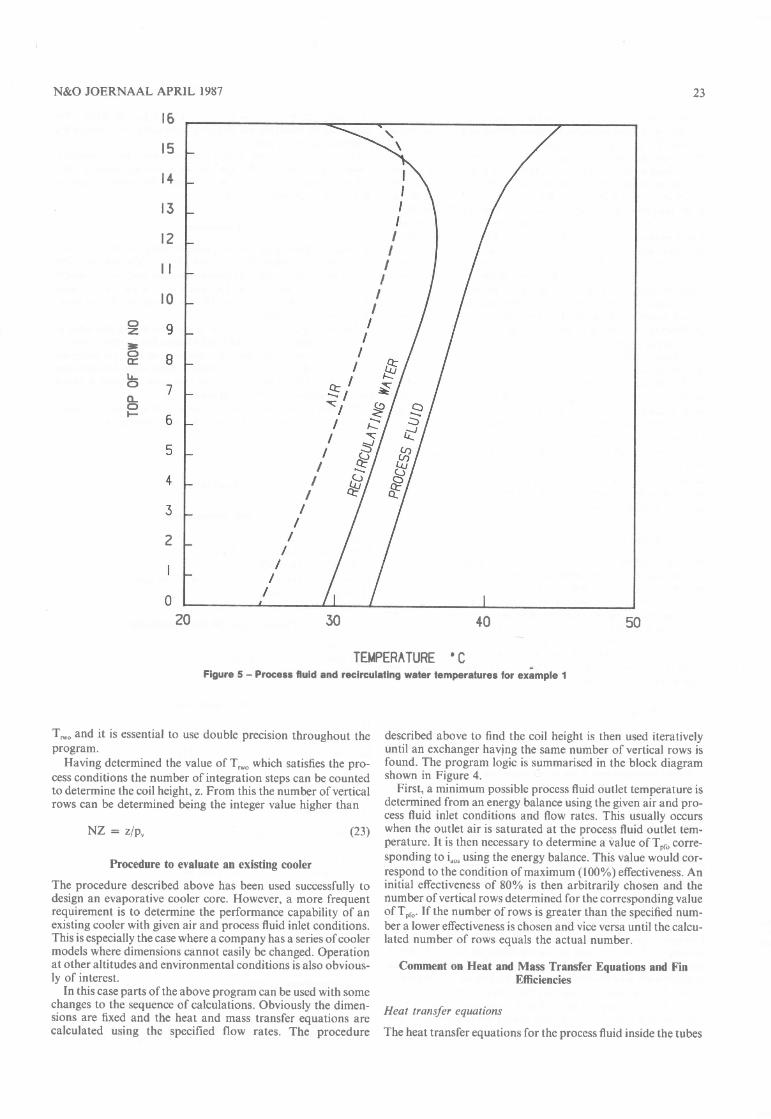
TEMPERATURE 'CFigure 5 - Process lluid and recirculating water temperatures tor eximple 1
(23)
IIIIII
II
I
24
are the same as for conventional heat exchangers. It is recom-mended here that the more modern Pethukov [7] equation orGnielinski t8l equation be used rather than the traditionalDittus and Boelter or Sieder and Tate equations.
The heat transfer coefficient between the outside core surfaceand the air-water interface presents a problem since it is ratherdependent on core geometry. A number of correlations such asthose suggested by Leidenfrost and Korenic [, 2] and Mizu-shina et al [3] exist, but they are rather limited in their applica-tion. Correlations for finned surfaces in particular are a prob-lem since they are linked to a fin efficiency which is generally lowfor wetted surfaces. The obvious solution to this predicament isthat values for a particular geometry have to be determinedexperimentally if a reasonably accurate answer is desired.
The same argument applies to the mass transfer coefficient atthe air-water interface which is analogous to the heat transfercoefficients in multi-tube heat exchangers with or without fins.There are no general correlations which can be used to deter-mine these coefficients although a heat-mass transfer analogymay be resorted to as a first approximation.
Mizushina et al [9] describe an experiment in which both a,*
and K are determined using measurements of temperature in therecirculating water film and the air. Since measurement of filmsurface temperatures presents some problems it would be pos-sible to determine d,* by subtraction if the cooler were operatedas a normal cooling tower in one instance (without processfluid) and evaporative cooler in the other. The value of a,* ob-tained could be based on the outside tube area avoiding theproblem of fin efficiency. For the purpose of testing the pro-gram Mizushina's correlations for c.* and K were employed.
Air Psychrometric Properties
Whereas Mizushina [3] recommended the use of a linear equa-tion linking saturation temperature and enthalpy, this was con-sidered an unnecessary approximation since it is possible, usinga digital computer, to write a short subrotrtine which takes allvariables including air pressure into account. This was donewith equations recommended by Johannsen [ 0] which can alsobe found in ASHRAE U ll and Schmidt [2].
An additional subroutine was also written making it possibleto determine saturation temperature from enthalpy using theroutine referred to above.
Physical Properties of Air and Water
Subroutines were written to determine the various physicalproperties of air-water mixtures and water in terms of pressureand temperature.
Since the properties of the air or water are generally tempera-ture dependent it is desirable that they be calculated at the tem-peratures applicable at the particular location in the coolerwhere the various coefficients have to be calculated. This re-quires that the coefficients be calculated repetitively during theintegration process if high accuracy is required. In the examplesdiscussed below properties were calculated at average coolertemperatures rather than local values. It is intended to modilythe program to accommodate the latter possibility.
Some Practical Calculations
Example I gives the size of a cooler determined with the givenprocess fluid and air conditions while Example 2 gives the resultfor a cooler of fixed dimensions and given inlet conditions. Thetempereature distributions lor the first example are shown inFigure 5. It should be noted that the outlet temperature on thegraph, 32,3" C, is slightly lower than the specified value, 32,5" C,as an integral number of rows (vertically) has to be chosen. Thenumber of vertical rows used in the above examples is consider-
R&D JOURNAL APRIL 1987
ably higher than is usually employed in practice. However, thiswas done to illustrate the extreme conditions over which theprogram can be applied.
It is also not usual to employ coolers where the wet bulb airtemperature profile will cross the recirculating water profile,although such cases should be accounted for when a cooler isemployed at off-design conditions.
Conclusion
A successful procedure for designing or rating evaporative cool-ers has been described. The accuracy of the results obtained withthe program is heavily dependent on heat and mass transfercorrelations for the recirculating water and the air. These valuesshould be obtained experimentally if a reasonable degree of ac-curacy is to be expected.
The recirculating water temperature need not be restricted toa value between the air outlet and process fluid outlet tempera-tures, as can be clearly seen in example l. In fact, the programfor rating coils, as used for example 2, must allow for solutionswhere the inlet temperature of the recirculating water is belowthe air outlet wet bulb temperature.
Obviously the lowest limit for recirculating water tempera-ture would be the wet bulb value for the entering air.
Example I
Tube arrangement
Tube outside diameter - 15 mmTube inside diameter _ 13 mmHorizontal tube pitch _ 30 mmVertical tube pitch _ J3 . 15 - 25,98 mm(Triangular arrangement)
Process Fluid (Water) Conditions
Flowrate _5kg/sInlet temperature _ 45" COutlet temperature _ 32,5" C
Air Conditions
Dry bulb temperature _ 25" CWet bulb temperature _ l8' CBarometric pressure _ 760 mm Hg
Results
(1) Dimensions
No. of rows across _ 29No. of vertical rows _ 16
Width _ 0,885 mLength _ 1,671 mHeight _ 0,416 m
(ti) Air
Outlet temperature _ 32,21" C (assuming saturation)Flow rate : 4,134 kg/s.
(iii) Re circulating Water
Inlet and outlet temperature _ 29.,44" CFlow rate _ 2,355 kg/s
(iv) Co il capacity _ 261,05 kW
N&O JOERNAAL APRIL 1987
Example 2
Coil Dimensions
Tube O.D. _ 15,0 mmTube I.D. - 13,0 mmNo. of rows across - 26No. of rows vertically - l0Horizontal pitch - 30 mmVertical pitch - 25,98 mmCoil Breadth _ Coil Length - 0,78 rn
Process Fluid
Flow rate - 4,5 kg/sInlet temperature _ 50'C
Air and Recirculating Water
Inlet dry bulb temperature - 25,0" CInlet wet bulb temperature _ 18,0"CBarometric pressure _ 7 60 mmAir mass flow rate _ 1,85 kg/sRecirculating water flow rate - 2,5 kgls
Results
Process fluid outlet temperature - 42,1" CAir outlet temperature - 35,3" C
25
Capacity - 149,2 kWRecirculating water temperature In/Out _ 36,7"C
References
l. Leidenfrost, W., and Korenic, B., "Evaporative Cooling and Heat TransferAugmentation related to Reduced Condenser Temperatures", Heat Transkr En-gineering, Vol. 3, nos. 3-4, January-June 1982, pp. 38-59.
2. Leidenfrost, W., and Korenic, B., "Analysis of Evaporative Cooling En-hancement of Condenser Efficiency and of Coefficient of Performance", Wtirme-und Stoffilbertrogung No. 12, (1979), pp. 5-23.
3. Mizushina T., Ito, R., and Miyashita, H., "Characteristics and Methods ofThermal Design of Evaporative Coolers", International Chemical Engineering,Vol. 8, No. 3, July 1968, pp. 532-538.
4. Webb, R. L., "A Unified Theoretical Treatment for Thermal Analysis ofCooling Towers, Evaporative Condensers and Fluid Coolers" , ASH RAE Trans-ac'tions KC-84-07, No. 3 pp. 398-414.
5. Kreid, D. K., Johnson, B. M. and Faletti, D. W., "Approximate Analysis ofHeat Transfer from the Surface of a Wet Finned Heat Exchanger", ASME paper78-HT-26, N.Y., 1978.
6. Perez-Blanco, H. and Linkous, R. L., "I-Jse of an Overall Heat TransferCoefficient to calculate Performance of an Evaporative Cooler", Oak RidgeNational Laboratory TM-8450, February 1983.
7. Pethukov, B. S.., "Heat Transfer and Friction in Turbulent Pipe Flow withvariable Physical Properties", Advences in Heat Transfer (eds. J. P. Hartnett andT. F. Irvine), Academic Press, New York, pp. 504-564, 1970.
8. Gnielinski, V., "Forsche, Ing. Wes", Vol. 41, No. l,1975.9. Mizushina, T., Ito, R., and Miyashit&, H., "Experimental Study of an Evapo-
rative Cooler", Inlernational Chemical Engineering, Vol. 7, No. 4, 1967.10. Johannsen, A., "Plotting Psychrometric Charts by Computer", The South
A.frican Mechanical Engineer, Vol. 32, July 1982.I l. ASHRAE Handbook and Product Directory, Fundamentals, Ch 5, New
York, 1972.12. Schmidt, 8., "Properties of Water and Steam in SI- units", Springer-Verlag,
Berlin, 1969.13. Stoecker, W. F. and Jones, J. W., "Refrigeraton and Air-conditioning",
McGraw-Hill, 2nd Ed., 1982.